JP2014201246A - Hybrid vehicle - Google Patents
Hybrid vehicle Download PDFInfo
- Publication number
- JP2014201246A JP2014201246A JP2013080330A JP2013080330A JP2014201246A JP 2014201246 A JP2014201246 A JP 2014201246A JP 2013080330 A JP2013080330 A JP 2013080330A JP 2013080330 A JP2013080330 A JP 2013080330A JP 2014201246 A JP2014201246 A JP 2014201246A
- Authority
- JP
- Japan
- Prior art keywords
- power
- engine
- motor
- hybrid vehicle
- charge
- Prior art date
- Legal status (The legal status is an assumption and is not a legal conclusion. Google has not performed a legal analysis and makes no representation as to the accuracy of the status listed.)
- Pending
Links
Images


Classifications
-
- B—PERFORMING OPERATIONS; TRANSPORTING
- B60—VEHICLES IN GENERAL
- B60W—CONJOINT CONTROL OF VEHICLE SUB-UNITS OF DIFFERENT TYPE OR DIFFERENT FUNCTION; CONTROL SYSTEMS SPECIALLY ADAPTED FOR HYBRID VEHICLES; ROAD VEHICLE DRIVE CONTROL SYSTEMS FOR PURPOSES NOT RELATED TO THE CONTROL OF A PARTICULAR SUB-UNIT
- B60W10/00—Conjoint control of vehicle sub-units of different type or different function
- B60W10/04—Conjoint control of vehicle sub-units of different type or different function including control of propulsion units
- B60W10/06—Conjoint control of vehicle sub-units of different type or different function including control of propulsion units including control of combustion engines
-
- B—PERFORMING OPERATIONS; TRANSPORTING
- B60—VEHICLES IN GENERAL
- B60W—CONJOINT CONTROL OF VEHICLE SUB-UNITS OF DIFFERENT TYPE OR DIFFERENT FUNCTION; CONTROL SYSTEMS SPECIALLY ADAPTED FOR HYBRID VEHICLES; ROAD VEHICLE DRIVE CONTROL SYSTEMS FOR PURPOSES NOT RELATED TO THE CONTROL OF A PARTICULAR SUB-UNIT
- B60W10/00—Conjoint control of vehicle sub-units of different type or different function
- B60W10/24—Conjoint control of vehicle sub-units of different type or different function including control of energy storage means
- B60W10/26—Conjoint control of vehicle sub-units of different type or different function including control of energy storage means for electrical energy, e.g. batteries or capacitors
-
- B—PERFORMING OPERATIONS; TRANSPORTING
- B60—VEHICLES IN GENERAL
- B60W—CONJOINT CONTROL OF VEHICLE SUB-UNITS OF DIFFERENT TYPE OR DIFFERENT FUNCTION; CONTROL SYSTEMS SPECIALLY ADAPTED FOR HYBRID VEHICLES; ROAD VEHICLE DRIVE CONTROL SYSTEMS FOR PURPOSES NOT RELATED TO THE CONTROL OF A PARTICULAR SUB-UNIT
- B60W10/00—Conjoint control of vehicle sub-units of different type or different function
- B60W10/04—Conjoint control of vehicle sub-units of different type or different function including control of propulsion units
- B60W10/08—Conjoint control of vehicle sub-units of different type or different function including control of propulsion units including control of electric propulsion units, e.g. motors or generators
-
- B—PERFORMING OPERATIONS; TRANSPORTING
- B60—VEHICLES IN GENERAL
- B60W—CONJOINT CONTROL OF VEHICLE SUB-UNITS OF DIFFERENT TYPE OR DIFFERENT FUNCTION; CONTROL SYSTEMS SPECIALLY ADAPTED FOR HYBRID VEHICLES; ROAD VEHICLE DRIVE CONTROL SYSTEMS FOR PURPOSES NOT RELATED TO THE CONTROL OF A PARTICULAR SUB-UNIT
- B60W20/00—Control systems specially adapted for hybrid vehicles
- B60W20/10—Controlling the power contribution of each of the prime movers to meet required power demand
- B60W20/13—Controlling the power contribution of each of the prime movers to meet required power demand in order to stay within battery power input or output limits; in order to prevent overcharging or battery depletion
-
- B—PERFORMING OPERATIONS; TRANSPORTING
- B60—VEHICLES IN GENERAL
- B60W—CONJOINT CONTROL OF VEHICLE SUB-UNITS OF DIFFERENT TYPE OR DIFFERENT FUNCTION; CONTROL SYSTEMS SPECIALLY ADAPTED FOR HYBRID VEHICLES; ROAD VEHICLE DRIVE CONTROL SYSTEMS FOR PURPOSES NOT RELATED TO THE CONTROL OF A PARTICULAR SUB-UNIT
- B60W2510/00—Input parameters relating to a particular sub-units
- B60W2510/24—Energy storage means
- B60W2510/242—Energy storage means for electrical energy
- B60W2510/244—Charge state
-
- B—PERFORMING OPERATIONS; TRANSPORTING
- B60—VEHICLES IN GENERAL
- B60W—CONJOINT CONTROL OF VEHICLE SUB-UNITS OF DIFFERENT TYPE OR DIFFERENT FUNCTION; CONTROL SYSTEMS SPECIALLY ADAPTED FOR HYBRID VEHICLES; ROAD VEHICLE DRIVE CONTROL SYSTEMS FOR PURPOSES NOT RELATED TO THE CONTROL OF A PARTICULAR SUB-UNIT
- B60W2710/00—Output or target parameters relating to a particular sub-units
- B60W2710/08—Electric propulsion units
- B60W2710/086—Power
-
- Y—GENERAL TAGGING OF NEW TECHNOLOGICAL DEVELOPMENTS; GENERAL TAGGING OF CROSS-SECTIONAL TECHNOLOGIES SPANNING OVER SEVERAL SECTIONS OF THE IPC; TECHNICAL SUBJECTS COVERED BY FORMER USPC CROSS-REFERENCE ART COLLECTIONS [XRACs] AND DIGESTS
- Y10—TECHNICAL SUBJECTS COVERED BY FORMER USPC
- Y10S—TECHNICAL SUBJECTS COVERED BY FORMER USPC CROSS-REFERENCE ART COLLECTIONS [XRACs] AND DIGESTS
- Y10S903/00—Hybrid electric vehicles, HEVS
- Y10S903/902—Prime movers comprising electrical and internal combustion motors
- Y10S903/903—Prime movers comprising electrical and internal combustion motors having energy storing means, e.g. battery, capacitor
- Y10S903/93—Conjoint control of different elements
Landscapes
- Engineering & Computer Science (AREA)
- Chemical & Material Sciences (AREA)
- Combustion & Propulsion (AREA)
- Transportation (AREA)
- Mechanical Engineering (AREA)
- Automation & Control Theory (AREA)
- Hybrid Electric Vehicles (AREA)
- Electric Propulsion And Braking For Vehicles (AREA)
Abstract
Description
本発明は、ハイブリッド車両に関し、詳しくは、エンジンと、エンジンからの動力を用いて発電するモータと、モータと電力をやりとりするバッテリと、を備えるハイブリッド車両に関する。 The present invention relates to a hybrid vehicle, and more particularly, to a hybrid vehicle including an engine, a motor that generates electric power using power from the engine, and a battery that exchanges electric power with the motor.
従来、この種のハイブリッド車両としては、エンジンと、エンジンの出力によって発電する第1モータジェネレータと、車両駆動力発生用の電動機として用いられる第2モータジェネレータと、第1モータジェネレータおよび第2モータジェネレータと電力をやりとりする蓄電装置と、を備え、ユーザのスイッチ操作によって充電要求が検知されると実際の蓄電装置のSOCより低く制御SOCを設定して蓄電装置のSOCが制御SOCになるようエンジンと第1モータジェネレータと第2モータジェネレータとを制御するものが提案されている(例えば、特許文献1参照)。この車両では、こうした制御により、蓄電装置の充電の機会をより多くして、ユーザ要求に応じた車両運転を実現している。 Conventionally, this type of hybrid vehicle includes an engine, a first motor generator that generates electric power by the output of the engine, a second motor generator that is used as an electric motor for generating vehicle driving force, a first motor generator, and a second motor generator. And a power storage device that exchanges power with the engine, and when the charging request is detected by a user's switch operation, the control SOC is set lower than the SOC of the actual power storage device and the SOC of the power storage device becomes the control SOC. A device that controls the first motor generator and the second motor generator has been proposed (see, for example, Patent Document 1). In this vehicle, by such control, the chance of charging the power storage device is increased, and the vehicle operation according to the user request is realized.
上述のハイブリッド車両において、例えば、目的地が排ガスを一切排出しない自動車のみに走行が許可される地域である場合など、エンジンを運転せずに第2モータジェネレータからの動力のみで走行するモータ走行に備えて、バッテリの蓄電割合が目標蓄電割合まで充電されることをユーザが望む場合がある。こうしたユーザの要求に対応する手法として、ユーザが所定のスイッチを操作したときにエンジンからの動力を用いて第1モータジェネレータで発電した電力でバッテリを充電することによりバッテリの蓄電割合を目標蓄電割合にする手法が考えられるが、エンジンからの動力を用いて発電を行なうから、燃料の消費量が増加し、燃費が悪くなる場合がある。 In the hybrid vehicle described above, for example, when the destination is an area where only a vehicle that does not emit any exhaust gas is allowed to travel, the motor travels only by the power from the second motor generator without operating the engine. In preparation, the user may desire that the battery charge rate is charged to the target charge rate. As a method corresponding to such a user request, when the user operates a predetermined switch, the battery is charged with the electric power generated by the first motor generator using the power from the engine, so that the storage ratio of the battery is set to the target storage ratio. However, since power generation is performed using the power from the engine, fuel consumption may increase and fuel consumption may deteriorate.
本発明のハイブリッド車両は、モータの発電電力の増加を指示する充電促進指示スイッチがオンされたときに、燃費が悪くなる制御が行なわれていることをユーザに認識させることを主目的とする。 The main purpose of the hybrid vehicle of the present invention is to allow the user to recognize that the control for reducing the fuel consumption is performed when the charge promotion instruction switch for instructing an increase in the power generated by the motor is turned on.
本発明のハイブリッド車両は、上述の主目的を達成するために以下の手段を採った。 The hybrid vehicle of the present invention employs the following means in order to achieve the main object described above.
本発明のハイブリッド車両では、
エンジンと、前記エンジンからの動力を用いて発電するモータと、前記モータと電力をやりとりするバッテリと、を備えるハイブリッド車両であって、
オンした後はオンする前に比べて前記モータの発電電力を増加させることを指示する充電促進指示スイッチと、
情報を報知する報知手段と、
前記充電促進指示スイッチがオンされているときには、前記報知手段に充電促進モードであることが報知されるよう前記報知手段を制御する制御手段と、
を備えることを要旨とする。
In the hybrid vehicle of the present invention,
A hybrid vehicle comprising an engine, a motor that generates electric power using power from the engine, and a battery that exchanges electric power with the motor,
A charge promotion instruction switch for instructing to increase the generated power of the motor after turning on, compared to before turning on;
An informing means for informing the information;
Control means for controlling the notifying means so that the notifying means is informed that it is in the charge promotion mode when the charging promotion instruction switch is on;
It is a summary to provide.
この本発明のハイブリッド車両では、充電促進指示スイッチがオンされているときには、報知手段にモータの発電電力の増加が報知されるよう報知手段を制御する。モータは、エンジンからの動力で発電するため、モータの発電電力が増加すると、エンジンの燃料消費量も増加し、燃費が悪化する。充電促進指示スイッチがオンされているときには、報知手段に充電促進モードであることが報知されるよう報知手段を制御することにより、モータの発電電力の増加うあエンジンからの動力の増加,燃料消費量の増加、すなわち、燃費が悪くなる制御が行われていることをユーザに認識させることができる。 In the hybrid vehicle of the present invention, when the charge promotion instruction switch is turned on, the notification means is controlled so that the notification means notifies the increase in the generated power of the motor. Since the motor generates power with the power from the engine, if the power generated by the motor increases, the fuel consumption of the engine also increases and the fuel consumption deteriorates. When the charging promotion instruction switch is turned on, the notification means is controlled so that the notification means is informed of the charge promotion mode, so that the power generated from the engine increases, the fuel consumption increases. It is possible to make the user recognize that the amount is increased, that is, the control for reducing the fuel consumption is being performed.
こうした本発明のハイブリッド車両において、前記報知手段は、画像を表示可能な手段であり、前記制御手段は、前記充電促進指示スイッチがオンされているときには、前記報知手段に所定の画像が表示されるよう前記報知手段を制御する手段であるものとすることもできる。こうすれば、燃料の消費量の増加をユーザに視認させることができる。この場合において、前記制御手段は、前記充電促進指示スイッチがオンされているときには、前記所定の画像の少なくとも一部の色がオフされているときの色と異なる色になるよう前記報知手段を制御する手段であるものとすることもできるし、前記制御手段は、前記充電促進指示スイッチがオンされているときには、前記所定の画像の少なくとも一部が点滅するよう前記報知手段を制御する手段であるものとすることもできる。 In such a hybrid vehicle of the present invention, the notification means is means capable of displaying an image, and the control means displays a predetermined image on the notification means when the charging promotion instruction switch is turned on. It can also be a means for controlling the notification means. In this way, an increase in fuel consumption can be visually recognized by the user. In this case, when the charging promotion instruction switch is turned on, the control means controls the notifying means so that at least a part of the color of the predetermined image is different from the color when turned off. The control means is means for controlling the notification means so that at least a part of the predetermined image blinks when the charging promotion instruction switch is turned on. It can also be.
こうした報知手段を備える態様の本発明のハイブリッド車両において、前記制御手段は、前記充電促進指示スイッチがオンされているときには、前記蓄電量が目標蓄電量に至るまでに消費される燃料消費量が表示されるよう前記報知手段を制御する手段であるものとすることもできる。こうすれば、充電促進指示スイッチがオンされてから蓄電量が目標蓄電量になるまでの燃料消費量をユーザに認識させることができ、ユーザに燃料を消費してもバッテリの蓄電量を増やすかどうかの判断を促すことができる。この場合において、前記制御手段は、前記燃料消費量と燃料単価とに基づいて前記モータの発電電力の増加がなされている最中に消費する燃料の料金が表示されるよう前記報知手段を制御する手段であるものとすることもできる。こうすれば、モータの発電電力の増加がなされている最中に消費する燃料の料金をユーザに報知することができ、ユーザに燃料を消費してもバッテリの蓄電量を増やすかどうかの判断を促すことができる。 In the hybrid vehicle of the present invention having such a notification means, the control means displays a fuel consumption amount consumed until the charged amount reaches the target charged amount when the charging promotion instruction switch is turned on. It can also be a means for controlling the notification means. In this way, the user can recognize the amount of fuel consumed from when the charge promotion instruction switch is turned on until the amount of electricity stored reaches the target amount of electricity stored, and whether the user can increase the amount of electricity stored in the battery even if the user consumes fuel. Judgment of whether or not can be encouraged. In this case, the control means controls the notifying means so that the charge of the fuel consumed while the generated power of the motor is being increased is displayed based on the fuel consumption amount and the fuel unit price. It can also be a means. In this way, it is possible to inform the user of the charge of fuel consumed while the power generated by the motor is being increased, and to determine whether to increase the amount of charge in the battery even if the user consumes fuel. Can be urged.
さらに、本発明のハイブリッド車両において、外部の機器が接続されたときに前記バッテリから前記外部の機器に電力を供給可能な外部電力供給装置を備えるものとすることもできる。 Furthermore, the hybrid vehicle of the present invention may include an external power supply device capable of supplying power from the battery to the external device when an external device is connected.
次に、本発明を実施するための形態を実施例を用いて説明する。 Next, the form for implementing this invention is demonstrated using an Example.
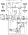
図1は、本発明の第1実施例としてのハイブリッド自動車20の構成の概略を示す構成図である。第1実施例のハイブリッド自動車20は、図1に示すように、ガソリンや軽油などを燃料として動力を出力するエンジン22と、エンジン22を駆動制御するエンジン用電子制御ユニット(以下、エンジンECUという)24と、エンジン22のクランクシャフト26にキャリアが接続されると共に駆動輪38a,38bにデファレンシャルギヤ37を介して連結された駆動軸36にリングギヤが接続されたシングルピニオン式のプラネタリギヤ30と、例えば同期発電電動機として構成されて回転子がプラネタリギヤ30のサンギヤに接続されたモータMG1と、例えば同期発電電動機として構成されて回転子が駆動軸36に接続されたモータMG2と、モータMG1,MG2を駆動するためのインバータ41,42と、インバータ41,42の図示しないスイッチング素子をスイッチング制御することによってモータMG1,MG2を駆動制御するモータ用電子制御ユニット(以下、モータECUという)40と、例えばリチウムイオン二次電池として構成されてインバータ41,42を介してモータMG1,MG2と電力をやりとりする高電圧バッテリ50と、高電圧バッテリ50を管理するバッテリ用電子制御ユニット(以下、バッテリECUという)52と、家庭用電源などの外部電源に接続されて高電圧バッテリ50を充電可能な充電器60と、車両の構成要素でない外部機器(例えば、家庭用電化製品など)のプラグを差込可能なコンセント94と、コンセント94に外部機器のプラグが差し込まれているときにインバータ41,42や高電圧バッテリ50が接続された電力ライン54の直流電力を所定電圧(例えば100Vなど)の交流電力に変換してコンセント94(外部機器)に供給可能なDC/AC変換器96と、入力された画像情報を表示すると共にユーザが画面に表示された画像を手で触れたり専用のペンで触れると触れられた画面位置を感知して情報信号を出力するタッチパネル98と、車両全体を制御するハイブリッド用電子制御ユニット(以下、HVECUという)70と、を備える。なお、コンセント94とDC/AC変換器96とが本発明の「外部電力供給装置」に相当する。
FIG. 1 is a configuration diagram showing an outline of the configuration of a
エンジンECU24は、図示しないが、CPUを中心とするマイクロプロセッサとして構成されており、CPUの他に、処理プログラムを記憶するROMやデータを一時的に記憶するRAM,入出力ポート,通信ポートを備える。エンジンECU24には、エンジン22の状態を検出する種々のセンサからの信号、例えば、クランクシャフト26の回転位置を検出するクランクポジションセンサからのクランクポジションやエンジン22の冷却水の温度を検出する水温センサからの冷却水温Tw,スロットルバルブのポジションを検出するスロットルバルブポジションセンサからのスロットルポジション,吸気管に取り付けられたエアフローメータからの吸入空気量Qaなどの信号が入力ポートを介して入力されている。また、エンジンECU24からは、エンジン22を駆動するための種々の制御信号、例えば、燃料噴射弁への駆動信号や、スロットルバルブのポジションを調節するスロットルモータへの駆動信号、イグニッションコイルへの制御信号などが出力ポートを介して出力されている。エンジンECU24は、HVECU70と通信しており、HVECU70からの制御信号によりエンジン22を運転制御すると共に必要に応じてエンジン22の運転状態に関するデータを出力する。なお、エンジンECU24は、クランクポジションセンサからのクランクポジションに基づいてクランクシャフト26の回転数、即ちエンジン22の回転数Neも演算している。
Although not shown, the engine ECU 24 is configured as a microprocessor centered on a CPU, and includes a ROM for storing a processing program, a RAM for temporarily storing data, an input / output port, and a communication port in addition to the CPU. . The engine ECU 24 includes signals from various sensors that detect the state of the
モータECU40は、図示しないが、CPUを中心とするマイクロプロセッサとして構成されており、CPUの他に、処理プログラムを記憶するROMやデータを一時的に記憶するRAM,入出力ポート,通信ポートを備える。モータECU40には、モータMG1,MG2を駆動制御するために必要な信号、例えばモータMG1,MG2の回転子の回転位置を検出する回転位置検出センサ43,44からの回転位置θm1,θm2や図示しない電流センサにより検出されるモータMG1,MG2に印加される相電流などが入力ポートを介して入力されており、モータECU40からは、インバータ41,42の図示しないスイッチング素子へのスイッチング制御信号などが出力ポートを介して出力されている。また、モータECU40は、HVECU70と通信しており、HVECU70からの制御信号によってモータMG1,MG2を駆動制御すると共に必要に応じてモータMG1,MG2の運転状態に関するデータをHVECU70に出力する。なお、モータECU40は、回転位置検出センサ43,44からのモータMG1,MG2の回転子の回転位置θm1,θm2に基づいてモータMG1,MG2の回転角速度ωm1,ωm2や回転数Nm1,Nm2も演算している。
Although not shown, the
バッテリECU52は、図示しないが、CPUを中心とするマイクロプロセッサとして構成されており、CPUの他に、処理プログラムを記憶するROMやデータを一時的に記憶するRAM,入出力ポート,通信ポートを備える。バッテリECU52には、高電圧バッテリ50を管理するのに必要な信号、例えば、高電圧バッテリ50の端子間に設置された電圧センサ51aからの端子間電圧Vbや高電圧バッテリ50の出力端子に接続された電力ラインに取り付けられた電流センサ51bからの充放電電流Ib,高電圧バッテリ50に取り付けられた温度センサ51cからの電池温度Tbなどが入力されており、必要に応じて高電圧バッテリ50の状態に関するデータを通信によりHVECU70に送信する。また、バッテリECU52は、高電圧バッテリ50を管理するために、電流センサ51bにより検出された充放電電流Ibの積算値に基づいてそのときの高電圧バッテリ50から放電可能な電力の容量の全容量に対する割合である蓄電割合SOCを演算したり、演算した蓄電割合SOCと電池温度Tbとに基づいて高電圧バッテリ50を充放電してもよい許容入出力電力である入出力制限Win,Woutを演算したりしている。なお、高電圧バッテリ50の入出力制限Win,Woutは、電池温度Tbに基づいて入出力制限Win,Woutの基本値を設定し、高電圧バッテリ50の蓄電割合SOCに基づいて出力制限用補正係数と入力制限用補正係数とを設定し、設定した入出力制限Win,Woutの基本値に補正係数を乗じることにより設定することができる。
Although not shown, the battery ECU 52 is configured as a microprocessor centered on a CPU, and includes a ROM for storing a processing program, a RAM for temporarily storing data, an input / output port, and a communication port in addition to the CPU. . The battery ECU 52 is connected to a signal necessary for managing the
充電器60は、リレー62を介して高電圧系電力ライン54aに接続されており、電源プラグ68を介して供給される外部電源からの交流電力を直流電力に変換するAC/DCコンバータ66と、AC/DCコンバータ66からの直流電力の電圧を変換して高電圧系電力ライン54a側に供給するDC/DCコンバータ64と、を備える。
The
HVECU70は、図示しないが、CPUを中心とするマイクロプロセッサとして構成されており、CPUの他に、処理プログラムを記憶するROMやデータを一時的に記憶するRAM,入出力ポート,通信ポートを備える。HVECU70には、イグニッションスイッチ80からのイグニッション信号やシフトレバー81の操作位置を検出するシフトポジションセンサ82からのシフトポジションSP,アクセルペダル83の踏み込み量を検出するアクセルペダルポジションセンサ84からのアクセル開度Acc,ブレーキペダル85の踏み込み量を検出するブレーキペダルポジションセンサ86からのブレーキペダルポジションBP,車速センサ88からの車速V,外気温度センサ89からの外気温度Tout,SOC回復指示スイッチ90のオンオフを示すSOC回復指示信号,タッチパネル98からの情報信号などが入力ポートを介して入力されている。また、HVECU70は、タッチパネル98へ画像情報を出力している。HVECU70は、前述したように、エンジンECU24やモータECU40,バッテリECU52と通信ポートを介して接続されており、エンジンECU24やモータECU40,バッテリECU52と各種制御信号やデータのやりとりを行なっている。なお、シフトポジションSPとしては、駐車ポジション(Pポジション)や中立ポジション(Nポジション),前進走行用のドライブポジション(Dポジション),後進走行用のリバースポジション(Rポジション)などがある。
Although not shown, the
こうして構成された実施例のハイブリッド自動車20では、運転者によるアクセルペダルの踏み込み量に対応するアクセル開度Accと車速Vとに基づいて駆動軸36に出力すべき要求トルクTr*を計算し、この要求トルクTr*に対応する要求動力が駆動軸36に出力されるように、エンジン22とモータMG1とモータMG2とが運転制御される。エンジン22とモータMG1とモータMG2との運転制御としては、要求動力に見合う動力がエンジン22から出力されるようにエンジン22を運転制御すると共にエンジン22から出力される動力のすべてがプラネタリギヤ30とモータMG1とモータMG2とによってトルク変換されて駆動軸36に出力されるようモータMG1およびモータMG2を駆動制御するトルク変換運転モードや、要求動力と高電圧バッテリ50の充放電に必要な電力との和に見合う動力がエンジン22から出力されるようにエンジン22を運転制御すると共に高電圧バッテリ50の充放電を伴ってエンジン22から出力される動力の全部またはその一部がプラネタリギヤ30とモータMG1とモータMG2とによるトルク変換を伴って要求動力が駆動軸36に出力されるようモータMG1およびモータMG2を駆動制御する充放電運転モード,エンジン22の運転を停止してモータMG2からの要求動力に見合う動力を駆動軸36に出力するよう運転制御するモータ運転モードなどがある。なお、トルク変換運転モードと充放電運転モードとは、いずれもエンジン22の運転を伴って要求動力が駆動軸36に出力されるようエンジン22とモータMG1とモータMG2とを制御するモードであり、実質的な制御における差異はないため、以下、両者を合わせてエンジン運転モードという。
In the
また、実施例のハイブリッド自動車20では、自宅や予め設定された充電ポイントで車両をシステム停止した後に電源プラグ68が外部電源に接続されてその接続が接続検出センサ69によって検出されると、システムメインリレー55とリレー62とをオンとし、充電器60を制御して外部電源からの電力により高電圧バッテリ50を充電する。そして、高電圧バッテリ50の充電後にシステム起動したときには、高電圧バッテリ50の蓄電割合SOCがエンジン22の始動を行なうことができる程度に設定された閾値Shv(例えば、20%や30%など)に至るまでは、エンジン22からの動力とモータMG2からの動力とを用いて走行するハイブリッド走行に比してモータMG2からの動力だけを用いて走行するモータ走行を優先して走行するモータ走行優先モードによって走行し、高電圧バッテリ50の蓄電割合SOCが閾値Shvに至った以降は、モータ走行に比してハイブリッド走行を優先して走行するハイブリッド走行優先モードによって走行する。
Further, in the
モータ走行優先モードでは、アクセルペダル83の踏み込み量に対応するアクセル開度Accと車速Vとに基づいて走行に要求される(駆動軸36に出力すべき)要求トルクTr*を設定すると共に設定した要求トルクTr*に駆動軸36の回転数Nr(例えば、モータMG2の回転数Nm2や車速Vに換算係数を乗じて得られる回転数)を乗じて走行に要求される走行用パワーPdrv*を計算する。そして、走行用パワーPdrv*が高電圧バッテリ50の出力制限Wout以下のときには、エンジン22の運転を停止した状態でモータMG2から走行用パワーPdrv*を出力して駆動軸36に要求トルクTr*が出力されるようモータMG2を制御して、モータ走行によって走行する。走行用パワーPdrv*が高電圧バッテリ50の出力制限Woutより大きくなると、エンジン22を始動して、走行用パワーPdrv*をエンジン22から出力すべき要求パワーPe*に設定し、エンジン22から要求パワーPe*が出力されると共に駆動軸36に要求トルクTr*が出力されるようエンジン22とモータMG1,MG2とを制御して、ハイブリッド走行によって走行する。その後に、走行用パワーPdrv*が高電圧バッテリ50の出力制限Wout以下になると、エンジン22を運転を停止して、エンジン22の運転を停止して、モータMG2から走行用パワーPdrv*を出力して走行するモータ走行に戻る。
In the motor travel priority mode, the required torque Tr * required for travel (to be output to the drive shaft 36) is set and set based on the accelerator opening Acc corresponding to the depression amount of the
ハイブリッド走行優先モードでは、高電圧バッテリ50の蓄電割合SOCに応じて高電圧バッテリ50の充放電要求パワーPb*(高電圧バッテリ50から放電するときが負の値)を設定すると共に設定した充放電要求パワーPb*に走行用パワーPdrv*を加えてエンジン22から出力すべき要求パワーPe*を設定し、要求パワーPe*がエンジン22を比較的効率よく運転することができる最低パワーとして予め定められた運転用閾値Pop以上のときには、エンジン22から要求パワーPe*が出力されると共に駆動軸36に要求トルクTr*が出力されるようエンジン22とモータMG1とモータMG2とを制御して、ハイブリッド走行によって走行する。要求パワーPe*が運転用閾値Pop未満になると、エンジン22を比較的効率よく運転できないため、エンジン22の運転を停止してモータMG2から走行用パワーPdrv*を出力して走行するモータ走行に移行する。モータ走行によって走行している最中に運転者がアクセルペダル83を踏み込んで走行用パワーPdrv*が大きくなって要求パワーPe*が運転用閾値Pop以上になると、エンジン22を始動してエンジン22から要求パワーPe*を出力して走行するハイブリッド走行に移行する。なお、運転用閾値Popは、高電圧バッテリ50の出力制限Woutに比してかなり小さな値として定められている。
In the hybrid travel priority mode, the charge / discharge required power Pb * of the high voltage battery 50 (a negative value when discharging from the high voltage battery 50) is set according to the storage ratio SOC of the
次に、実施例のハイブリッド自動車20の動作、特に、ユーザによりSOC回復指示スイッチ90がオンされたときの動作について説明する。図2は、HVECU70により実行されるスイッチオン時処理ルーチンの一例を示すフローチャートである。このルーチンは、ユーザによりSOC回復指示スイッチ90がオンされたときに実行される。
Next, the operation of the
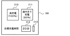
SOC回復指示スイッチオン時処理ルーチンの実行されると、HVECU70のCPU72は、バッテリECU52から蓄電割合SOCを入力する処理を実行し(ステップS100)、目標蓄電割合SOC*と目標充電時間tc*とを設定するための目標値選択画面の画面情報をタッチパネル98に送信し(ステップS110)、タッチパネル98から目標蓄電割合SOC*と目標充電時間tc*とが入力されるまで待つ(ステップS120)。ステップS110で画像情報を受信したタッチパネル38は、目標値選択画面を表示する。図3は、タッチパネル98に表示される目標値選択画面の一例を示す説明図である。タッチパネル98には、「満充電」,「途中まで充電」の文字を含む矩形のアイコンI10,I11と、目標充電時間を示す文字を含むアイコンI12と、「+」,「−」の文字を含むアイコンI13とが視認可能に表示されている。ユーザが表示されているアイコンI10,I11のうちの一つに触れると、タッチパネル98は、触れられたアイコンの位置情報に基づいて触れられたアイコンに表示されている充電状態の情報をユーザが入力した目標蓄電割合SOC*としてHVECU70に送信する。アイコンI13は、アイコンI12に表示される時間を設定するために用いられる。アイコンI13の「+」の文字をユーザが触れる度にアイコンI12に表示される目標時間が増加し、アイコンI13の「−」の文字をユーザが触れる度にアイコンI12に表示される目標時間が減少する。ユーザがアイコンI13を触れない状態が所定時間(例えば、10秒など)継続すると、タッチパネル98は、アイコンI13に表示されている時間を目標充電時間tc*としてHVECU70に送信する。このとき、アイコンI10,I12のうち、ユーザが触れたアイコンの色を変更するものとしたり、アイコン全体が点滅するものとしてもよい。
When the SOC recovery instruction switch-on processing routine is executed, the
こうして目標蓄電割合SOC*と目標充電時間tc*とが入力されると、燃料消費関連情報表示処理を実行する(ステップS130)。ここで、SOC回復指示スイッチオン時処理の説明を一旦中断し、燃料消費関連情報表示処理について説明する。 When the target power storage rate SOC * and the target charging time tc * are thus input, the fuel consumption related information display process is executed (step S130). Here, the description of the process when the SOC recovery instruction switch is turned on is temporarily interrupted, and the fuel consumption related information display process will be described.
図4は、燃料関連情報表示処理の一例を示すフローチャートである。燃料関連情報表示処理では、次式(1)を用いて目標充電時間tc*で現在の蓄電割合SOCである蓄電割合初期値SOCiを目標蓄電割合SOC*にするために単位時間当たりに高電圧バッテリ50で充放電が要求されるパワーを仮平均充放電パワーPbavtmpとして設定し(ステップS300)、仮平均充放電パワーPbavtmpと高電圧バッテリ50に許容される充電電力の最大値である上限充電パワーPbmaxとのうち小さい方の値を平均充放電パワーPbavとして設定する(ステップS210)。ここで、式(1)中、「Kw」は、高電圧バッテリ50の蓄電割合SOCを電力(パワー)に換算するための換算係数である。
FIG. 4 is a flowchart showing an example of the fuel related information display process. In the fuel-related information display process, a high voltage battery per unit time is used to set the storage ratio initial value SOCi, which is the current storage ratio SOC at the target charge time tc *, to the target storage ratio SOC * using the following equation (1). 50 is set as the temporary average charge / discharge power Pbavtmp (step S300), and the upper limit charge power Pbmax which is the maximum value of the temporary average charge / discharge power Pbavtmp and the charge power allowed for the
Pbavtmp=Kw・(SOC*-SOCi)/tc* (1) Pbavtmp = Kw ・ (SOC * -SOCi) / tc * (1)
こうして平均充放電パワーPbavを設定したら、SOC回復指示スイッチ90がオンされてから高電圧バッテリ50を充電しているときの車両の走行用パワーの平均値と予想される予想走行パワーPdavと平均充放電パワーPbavとの和のパワーを平均エンジンパワーPeavに設定し(ステップS320)、目標充電時間tc*と平均充放電パワーPbavと仮平均充放電パワーPbavtmpと予想走行パワーPdavとを用いて、次式(2)により、SOC回復指示スイッチ90がオンされてから車両が予想走行パワーPdavで走行したときに蓄電割合SOCが目標蓄電割合SOC*に至るまでの所要時間と推定される推定所要時間tendを演算する(ステップS330)。ここで、予想走行パワーPdavは、前回イグニッションスイッチ80がオンされてからオフされるまでの1トリップにおけるアクセル開度Accと車速Vとに基づく走行要求パワーPdrv*の平均値を用いるものとした。ここで、推定所要時間tendを演算するのは、高電圧バッテリ50には上限充電パワーPbmaxまでしか充電が許容されないため、SOC回復指示スイッチ90がオンされてから蓄電割合SOCが目標蓄電割合SOC*に至るまでの実際の所要時間は、ユーザが入力した目標充電時間tc*からずれる場合があるからである。推定所要時間tendを演算する際に前回イグニッションスイッチ80がオンされてからオフされるまでの1トリップにおける走行要求パワーPdrv*の平均値を用いることにより、アクセルの操作の仕方などユーザ個人の運転の癖などを反映させることができ、より精度よく推定所要時間tendを演算することができる。
When the average charging / discharging power Pbav is set in this way, the average value of the driving power of the vehicle when the
tend=tc*+(Pbavtmp−Pbav)・tc*/ (Pdav+Pbav) (2) tend = tc * + (Pbavtmp−Pbav) ・ tc * / (Pdav + Pbav) (2)
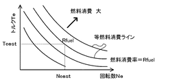
こうして推定所要時間tendを演算したら、続いて、設定した平均エンジンパワーPeavに基づいてエンジン22を運転すべき運転ポイントとしての推定エンジン回転数Neestと推定エンジントルクTeestとを設定する(ステップS340)。この設定は、エンジン22を効率よく動作させる動作ラインと平均エンジンパワーPeavとに基づいて行なわれる。エンジン22の動作ラインの一例と推定エンジン回転数Neestと推定エンジントルクTeestとを設定する様子を図5に示す。図示するように、推定エンジン回転数Neestと推定エンジントルクTeestは、動作ラインと平均エンジンパワーPeav(Neest×Teest)が一定の曲線との交点により求めることができる。
After the estimated required time tend is calculated in this way, the estimated engine speed Nest and the estimated engine torque Test are set as operating points at which the
こうして推定エンジン回転数Neestと推定エンジントルクTeestとを設定すると、推定エンジン回転数Neestと推定エンジントルクTeestとに基づいてエンジン22の燃料消費率Rfuelを設定すると共に設定した燃料消費率Rfuelに推定所要時間tendを乗じたものをエンジン22の予想燃料消費量Vfuelに設定する(ステップS350)。燃料消費率Rfuelは、推定エンジン回転数Neest,推定エンジントルクTeestとROM74に記憶されている燃料消費率マップとに基づいて行われる。燃料消費率マップの一例と燃料消費率Rfuelを設定する様子を図6に示す。図示するように、燃料消費率Rfuelは、推定エンジン回転数Neest,推定エンジントルクTeestが与えられると対応する燃料消費率として設定するものとした。
When the estimated engine speed Nest and the estimated engine torque Test are thus set, the fuel consumption rate Rfuel of the
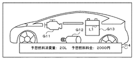
こうして燃料消費率Rfuelが設定されたら、予めROM74に記憶されている燃料単価Cupに設定した予想燃料消費量Vfuelを乗じたものを予想燃料料金Cfuelに設定して(ステップS360)、設定した予想燃料消費量Vfuelと予想燃料料金Cfuelがタッチパネル98に表示されるようタッチパネル98に画像情報を送信して(ステップS370)、本ルーチンを終了する。画像情報を受信したタッチパネル38は、エネルギー情報画面に設定した予想燃料消費量Vfuelと予想燃料料金Cfuelとを表示する処理を実行する。図7は、タッチパネル98に表示されるエネルギー情報画面の一例を示す説明図である。タッチパネル98は、エンジン,モータMG1,高電圧バッテリ50を示す図形G11〜G13と、予想燃料消費量Vfuel,予想燃料料金Cfuelを示す「予想燃料消費量:20L 予想燃料料金:2000円」の文字を含む矩形のアイコンI14とが視認可能に表示している。図形G13は、高電圧バッテリ50の現在の残容量SOCをユーザが認識できるよう境界線L1が表示されている。アイコンI14の各数字は、設定された予想燃料消費量Vfuel,予想燃料料金Cfuelを示している。これにより、SOC回復指示スイッチ90をオンしてから高電圧バッテリ50の蓄電割合SOCが目標蓄電割合SOC*になるまでに消費されると推定される燃料の量と燃料料金とをユーザに認識させることができ、ユーザに燃料を消費してもバッテリの蓄電量を増やすかどうかの判断を促すことができる。以上、燃料消費関連情報表示処理について説明した。
When the fuel consumption rate Rfuel is set in this way, the expected fuel charge Cfuel is set by multiplying the fuel unit price Cup previously stored in the
ここで、SOC回復指示スイッチオン時処理の説明に戻る。こうして燃料消費関連情報表示処理を実行したら(ステップS130)、続いて、入力された目標蓄電割合SOC*から蓄電割合初期値SOCiを減じたものを目標充電時間tc*で除して蓄電割合変化率Ksを設定し(ステップS140)、制御用目標蓄電割合SOCc*に蓄電割合変化率Ksを加えたものを制御用目標蓄電割合SOCc*に再設定する(ステップS150)。ここで、制御用目標蓄電割合SOCc*には、初期値としてステップS100の処理で入力された蓄電割合SOCが設定されるものとした。 Here, the description returns to the processing when the SOC recovery instruction switch is turned on. When the fuel consumption related information display process is executed in this way (step S130), the storage ratio change rate is obtained by dividing the input target storage ratio SOC * by subtracting the storage ratio initial value SOCi by the target charging time tc *. Ks is set (step S140), and the control target power storage ratio SOCc * plus the power storage ratio change rate Ks is reset to the control target power storage ratio SOCc * (step S150). Here, the power storage ratio SOC input in the process of step S100 is set as the initial value in the control target power storage ratio SOCc *.
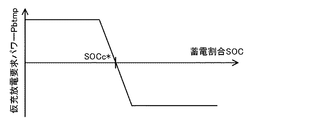
こうして制御用目標蓄電割合SOCc*を設定したら、高電圧バッテリ50の現在の蓄電割合SOCと制御用目標蓄電割合SOCc*とROM74に記憶されている仮充放電要求パワー設定マップとを用いて蓄電割合SOCを制御用目標蓄電割合SOCc*にするパワーである仮充放電要求パワーPbtmpを設定する(ステップS160)。仮充放電要求パワー設定マップの一例を図8に示す。図示するように、仮充放電要求パワーPbtmpは、蓄電割合SOCが制御用目標蓄電割合SOCc*より大きいときには制御用目標蓄電割合SOCc*と蓄電割合SOCとの差を打ち消すようにこの差が大きくなるほど絶対値が大きくなる傾向の負の値のパワーが設定され、蓄電割合SOCが制御用目標蓄電割合SOCc*より小さいときには制御用目標蓄電割合SOCc*と蓄電割合SOCとの差を打ち消すようにこの差が大きくなるほど大きくなる傾向の正の値のパワーが設定される。このように仮充放電要求パワーPbtmpを設定することにより、蓄電割合SOCを制御用目標蓄電割合SOCc*にすることができる。なお、仮充放電要求パワー設定マップは、制御用目標蓄電割合SOCc*毎にROM74に記憶されているものとする。
When the control target power storage ratio SOCc * is thus set, the power storage ratio is calculated using the current power storage ratio SOC of the high-
こうして仮充放電要求パワーPbtmpを設定したら、仮充放電要求パワーPbtmpと図4の燃料消費関連情報表示処理ルーチンのステップS310で用いられた上限充電パワーPbmaxとのうち小さい方の値を充放電要求パワーPb*として設定する(ステップS170)。このように充放電要求パワーPb*を設定すると、上述したハイブリッド走行優先モードによって、設定した充放電要求パワーPb*に走行用パワーPdrv*を加えたパワーをエンジン22から出力しながら走行するようエンジン22やモータMG1,MG2が制御される。これにより、エンジン22から出力されるパワーを用いてモータMG1で発電した電力で高電圧バッテリ50を充電しながら走行することができる。
When the temporary charge / discharge required power Pbtmp is set in this way, the smaller one of the temporary charge / discharge required power Pbtmp and the upper limit charge power Pbmax used in step S310 of the fuel consumption related information display processing routine of FIG. The power Pb * is set (step S170). When the charge / discharge required power Pb * is set in this way, the engine is driven so as to travel while outputting the power obtained by adding the travel power Pdrv * to the set charge / discharge required power Pb * from the
続いて、現在の蓄電割合SOCから蓄電割合初期値SOCiを減じたものを蓄電割合変化量dSOCに設定し(ステップS180)、上述したエネルギー情報画面において、タッチパネル98の高電圧バッテリ50を示す図形G13が点滅すると共に、図形G13において蓄電割合初期値SOCiを示す境界線L1から蓄電割合変化量dSOCまでの範囲が点滅され、エンジン22を示す図形G11からモータMG1を示す図形G12へエネルギーが出力されていることを示す矢印A1およびモータMG1を示す図形G12から高電圧バッテリ50を示す図形G31へエネルギーが出力されていることを示す矢印A2が表示されるよう、画像情報をタッチパネル98に送信する(ステップS190)。画像情報を受信したタッチパネル98は、エネルギー情報画面に高電圧バッテリ50を示す図形G13が点滅すると共に、図形G13において蓄電割合初期値SOCiを示す境界線L1から蓄電割合変化量dSOCまでの範囲が点滅され、図形G11から図形G12へと向かう矢印A1と図形G12から図形G13へと向かう矢印A2とを表示する処理を実行する。図9にエネルギー情報画面の一例を示す。モータMG1は、エンジン22からの動力で発電するため、モータMG1の発電電力が増加すると、燃料消費量が増加するため、車両の燃費が悪くなる。よって、エンジン22から動力を用いて駆動するモータMG1の発電電力で高電圧バッテリ50が充電されている最中に、こうした制御が行われていること、即ち、燃費が悪くなる類の制御が行なわれていることや、高電圧バッテリ50の蓄電割合SOCが蓄電割合初期値SOCiからどの程度変化したかをユーザに視認させることができる。
Subsequently, a value obtained by subtracting the storage ratio initial value SOCi from the current storage ratio SOC is set as the storage ratio change amount dSOC (step S180), and the graphic G13 showing the
こうしてエネルギー情報画面を表示したら、続いて、SOC回復指示スイッチ90がオフされたり、高電圧バッテリ50の蓄電割合SOCが目標蓄電割合SOC*に達したときなど、所定の終了条件が成立したか否かを調べる(ステップS200)。所定の終了条件が成立していないときには、バッテリECU52から蓄電割合SOCを入力し(ステップS210)、ステップS150の処理に戻り、所定の終了条件が成立するまで、ステップS140〜S210の処理を繰り返して、制御用目標蓄電割合SOCc*に蓄電割合変化率Ksを加えたものを制御用目標蓄電割合SOCc*に再設定し、高電圧バッテリ50の蓄電割合SOCと制御用目標蓄電割合SOCc*とROM74に記憶されている充放電要求パワー設定マップとを用いて仮充放電要求パワーPb*を設定し、仮充放電要求パワーPbtmpと上限充電パワーPbmaxとのうち小さい方の値を充放電要求パワーPb*として設定し、エネルギー情報画面において図形G13や図形G13において蓄電割合初期値SOCiを示す境界線L1から蓄電割合変化量dSOCまでの範囲を点滅させ、矢印A1,A2とを表示して、バッテリECU52から蓄電割合SOCを入力する。こうした処理により、上限充放電パワーPbmaxの範囲内のパワーで高電圧バッテリ50を充電するから、蓄電割合SOCを目標蓄電割合SOC*に向けて変化させることができる。このとき、蓄電割合SOCをユーザが入力した目標充電時間tc*を用いて設定した蓄電割合変化率Ksに基づく変化量で変化させることができるから、蓄電割合SOCをユーザが入力した目標充電時間tc*または目標充電時間tc*で目標蓄電割合SOC*にすることができ、ユーザの所望するタイミングにより近いタイミングで蓄電割合SOCを目標蓄電割合SOC*にすることができる。
When the energy information screen is displayed in this way, subsequently, whether or not a predetermined end condition is satisfied, such as when the SOC
そして、こうした処理を実行している最中に、所定の終了条件が成立したときには(ステップS200)、本ルーチンを終了する。 Then, when a predetermined end condition is satisfied during execution of such processing (step S200), this routine is ended.
以上説明した実施例のハイブリッド自動車20では、SOC回復指示スイッチ90がオンされているときには、蓄電割合SOCが増加するようエンジン22やモータMG1,MG2を制御すると共に、タッチパネル98のエネルギー情報画面に高電圧バッテリ50を示す図形G13を点滅させたり、図形G13において蓄電割合初期値SOCiを示す境界線L1から蓄電割合変化量dSOCまでの範囲を点滅させたり、矢印A1,A2を表示する。これにより、燃費が悪くなる類の制御が行なわれていることをユーザに視認させることができる。
In the
さらに、SOC回復指示スイッチ90がオンされたときには、予想燃料消費量Vfuelと予想燃料料金Cfuelがタッチパネル98に表示されるようタッチパネル98を制御する。これにより、高電圧バッテリ50から放電可能な電力の容量の全容量に対する割合である蓄電割合が増加するようエンジン22やモータMG1,MG2を制御している最中に消費が予想される燃料の消費量や料金をユーザに視認させることができ、ユーザに燃料を消費しても高電圧バッテリ50の蓄電割合SOCを増やすかどうかの判断を促すことができる。
Further, when the SOC
実施例のハイブリッド自動車20では、タッチパネル98のエネルギー情報画面に高電圧バッテリ50を示す図形G3が点滅すると共に、図形G3において蓄電割合初期値SOCiを示す線L1から蓄電割合変化量dSOCまでの範囲が点滅されるものとしたが、図形G3の色をSOC回復指示スイッチ90がオフのときと異なる色にしたり、図形G3において蓄電割合初期値SOCiを示す線L1から蓄電割合変化量dSOCまでの範囲の色を図形G3における他の範囲の色と異なるものとしてもよい。
In the
実施例のハイブリッド自動車20では、燃料消費量Vfuelや燃料料金Cfuelをタッチパネル98に表示するものとしたが、こうしたタッチパネル98に表示されるものに限定されるものではなく、図示しないスピーカから音声によりユーザに報知するものとしてもよい。
In the
実施例のハイブリッド自動車20では、図7に例示したエネルギー情報画面において、図形G11〜G13や境界線L1が表示されるものとしたが、図形G11〜G13や境界線L1が表示されず、アイコンI14のみが表示されるものとしてもよい。
In the
実施例のハイブリッド自動車20では、図9に例示したエネルギー情報画面において、図形G13が点滅したり、図形G13において蓄電割合初期値SOCiを示す境界線L1から蓄電割合変化量dSOCまでの範囲が点滅したり、矢印A1,A2が表示されるものとしたが、高電圧バッテリ50の蓄電割合SOCが増加するようエンジン22やモータMG1,MG2を制御していること、すなわち、モータMG1による発電電力を増加させていたり、エンジン22からの動力が増加していたり、エンジン22の燃料消費量が増加していること、すなわち、燃費が悪くなるような制御を実行中であることをユーザに視認させることができればよいから、例えば、図形G13が点滅せずに矢印A1,A2が表示されるものとしたり、図形G13が全体が点滅せずに図形G13において蓄電割合初期値SOCiを示す境界線L1から蓄電割合変化量dSOCまでの範囲のみが点滅して矢印A1,A2が表示されないものとしたり、エネルギー情報画面全体の色が特定の色に変化したりするものとしてもよい。
In the
実施例のハイブリッド自動車20では、ステップS330の処理で、目標充電時間tc*と平均充放電パワーPbavと仮平均充放電パワーPbavtmpと予想走行パワーPdavとを用いて推定所要時間tendを演算するものとしたが、ユーザから入力された目標蓄電割合SOC*と目標充電時間tcと蓄電割合SOCと推定所要時間tendとの関係を予め実験や解析などで求めておき、目標蓄電割合SOC*と目標充電時間tcと蓄電割合SOCとが与えられると求めた関係から推定所要時間tendを導出するもとしてもよい。
In the
実施例のハイブリッド自動車20では、SOC回復指示スイッチ90がオンされたときには、高電圧バッテリ50の蓄電割合SOCが目標蓄電割合SOC*に向かって増加するようエンジン22やモータMG1,MG2を制御するものとしたが、SOC回復指示スイッチ90がオンされたときには、モータMG1による発電電力がSOC回復指示スイッチ90がオンされる前より高くなればよいから、SOC回復指示スイッチ90がオンされたときには、例えば、エンジン22の運転を停止する際の走行用パワーPdrv*の閾値を出力制限Wout未満にしてエンジン22の運転を停止しがたくしたり、充放電要求パワーPb*も走行用パワーPdrv*を加えたものにさらに所定値のパワーを加えてエンジン22から出力すべき要求パワーPe*をSOC回復指示スイッチ90がオンされる前より大きくしたりしてもよい。
In the
実施例のハイブリッド自動車20では、モータMG2からの動力を駆動軸36に出力するものとしたが、図10の変形例のハイブリッド自動車120に例示するように、モータMG2からの動力を駆動軸36が接続された車軸(駆動輪38a,38bが接続された車軸)とは異なる車軸(図10における車輪39a,39bに接続された車軸)に接続するものとしてもよい。
In the
実施例のハイブリッド自動車20では、エンジン22からの動力をプラネタリギヤ30を介して駆動輪38a,38bに接続された駆動軸36に出力するものとしたが、図11の変形例のハイブリッド自動車220に例示するように、エンジン22のクランクシャフトに接続されたインナーロータ232と駆動輪38a,38bに動力を出力する駆動軸36に接続されたアウターロータ234とを有しエンジン22からの動力の一部を駆動軸36に伝達すると共に残余の動力を電力に変換する対ロータ電動機230を備えるものとしてもよい。
In the
実施例のハイブリッド自動車20では、エンジン22からの動力をプラネタリギヤ30を介して駆動輪38a,38bに接続された駆動軸36に出力すると共にモータMG2からの動力を駆動軸36に出力するものとしたが、図12の変形例のハイブリッド自動車320に例示するように、走行用の動力を出力するモータMG2と、エンジン22からの動力により発電するモータMG1と、を備えるいわゆるシリーズ型のハイブリッド車としても構わない。また、駆動輪38a,38bに接続された駆動軸36に無段変速機を介してモータを取り付けると共にモータの回転軸にクラッチを介してエンジン22を接続する構成とし、エンジン22からの動力をモータの回転軸と無段変速機とを介して駆動軸に出力すると共にモータからの動力を無段変速機を介して駆動軸に出力するものとしてもよい。さらに、こうした外部電源からの交流電力を直流電力に変換してバッテリを充電するためのDC/DCコンバータやAC/DCコンバータを有する充電器60を備えるいわゆるプラグインハイブリッド車に適用されるものに限定されるものではなく、図13の変形例のハイブリッド自動車420に例示するように、プラネタリギヤ30に接続されたエンジン22およびモータMG1と、駆動軸36に動力を入出力可能なモータMG2と、を備えるハイブリッド自動車420に適用するものとしてもよい。
In the
実施例の主要な要素と課題を解決するための手段の欄に記載した発明の主要な要素との対応関係について説明する。実施例では、エンジン22が「エンジン」に相当し、モータMG1が「モータ」に相当し、高電圧バッテリ50が「バッテリ」に相当し、SOC回復指示スイッチ90が「充電促進指示スイッチ」に相当し、タッチパネル98が「報知手段」に相当し、SOC回復指示スイッチ90がオンされているときには、タッチパネル98のエネルギー情報画面に高電圧バッテリ50を示す図形G3が点滅されると共に、図形G3において蓄電割合初期値SOCiを示す線L1から蓄電割合変化量dSOCまでの範囲が点滅され、図形G1から図形G2へと向かう矢印A1と図形G2から図形G3へと向かう矢印A2とが表示されるよう画像情報をタッチパネル98に送信するHVECU70とエンジンECU24とモータECU40とが「制御手段」に相当する。
The correspondence between the main elements of the embodiment and the main elements of the invention described in the column of means for solving the problems will be described. In the embodiment, the
ここで、「エンジン」としては、ガソリンまたは軽油などの炭化水素系の燃料により動力を出力するものに限定されるものではなく、水素エンジンなど走行用の動力を出力可能なものであれば如何なるタイプのエンジンであっても構わない。「モータ」としては、同期発電電動機として構成されたモータMG1に限定されるものではなく、誘導電動機など、エンジンからの動力を用いて発電するものであれば如何なるタイプの電動機であっても構わない。「バッテリ」としては、二次電池としての高電圧バッテリ50に限定されるものではなく、モータと電力をやりとりするものであれば如何なるものとしても構わない。「充電促進指示スイッチ」としては、SOC回復指示スイッチ90に限定されるものではなく、オンした後はオンする前に比べてモータの発電電力を増加させることを指示するものであれば如何なるものとしても構わない。「報知手段」としては、タッチパネル98に限定されるものではなく、情報を報知するものであれば如何なるものとしても構わない。「制御手段」としては、HVECU70とエンジンECU24とモータECU40とからなる組み合わせに限定されるものではなく単一の電子制御ユニットにより構成されるなどとしてもよい。また、「制御手段」としては、SOC回復指示スイッチ90がオンされているときには、高電圧バッテリ50から放電可能な電力の容量の全容量に対する割合である蓄電割合が増加するようエンジン22やモータMG1,MG2を制御したり、タッチパネル98のエネルギー情報画面に高電圧バッテリ50を示す図形G3が点滅されると共に、図形G3において蓄電割合初期値SOCiを示す線L1から蓄電割合変化量dSOCまでの範囲が点滅され、図形G1から図形G2へと向かう矢印A1と図形G2から図形G3へと向かう矢印A2とが表示されるよう画像情報をタッチパネル98に送信するものに限定されるものではなく、充電促進指示スイッチがオンされているときには、充電促進モードであることが報知されるよう報知手段を制御するものであれば如何なるものとしても構わない。
Here, the “engine” is not limited to one that outputs power using hydrocarbon fuel such as gasoline or light oil, but any type that can output driving power such as a hydrogen engine. It may be an engine. The “motor” is not limited to the motor MG1 configured as a synchronous generator motor, and may be any type of motor such as an induction motor that generates power using power from an engine. . The “battery” is not limited to the
なお、実施例の主要な要素と課題を解決するための手段の欄に記載した発明の主要な要素との対応関係は、実施例が課題を解決するための手段の欄に記載した発明を実施するための形態を具体的に説明するための一例であることから、課題を解決するための手段の欄に記載した発明の要素を限定するものではない。即ち、課題を解決するための手段の欄に記載した発明についての解釈はその欄の記載に基づいて行なわれるべきものであり、実施例は課題を解決するための手段の欄に記載した発明の具体的な一例に過ぎないものである。 The correspondence between the main elements of the embodiment and the main elements of the invention described in the column of means for solving the problem is the same as that of the embodiment described in the column of means for solving the problem. Therefore, the elements of the invention described in the column of means for solving the problems are not limited. That is, the interpretation of the invention described in the column of means for solving the problems should be made based on the description of the column, and the examples are those of the invention described in the column of means for solving the problems. It is only a specific example.
以上、本発明を実施するための形態について実施例を用いて説明したが、本発明はこうした実施例に何等限定されるものではなく、本発明の要旨を逸脱しない範囲内において、種々なる形態で実施し得ることは勿論である。 As mentioned above, although the form for implementing this invention was demonstrated using the Example, this invention is not limited at all to such an Example, In the range which does not deviate from the summary of this invention, it is with various forms. Of course, it can be implemented.
本発明は、ハイブリッド車両の製造産業などに利用可能である。 The present invention is applicable to the hybrid vehicle manufacturing industry and the like.
20,120,220,320,420 ハイブリッド自動車、22 エンジン、24 エンジン用電子制御ユニット(エンジンECU)、26 クランクシャフト、30 プラネタリギヤ、36 駆動軸、37 デファレンシャルギヤ、38a,38b 駆動輪、39a,39b 車輪、40 モータ用電子制御ユニット(モータECU)、41,42 インバータ、43,44 回転位置検出センサ、50 高電圧バッテリ、51a 電圧センサ、51b 電流センサ、51c 温度センサ、52 バッテリ用電子制御ユニット(バッテリECU)、54a 高電圧系電力ライン、54b 低電圧系電力ライン、56 システムメインリレー、57 DC/DCコンバータ、58 低電圧バッテリ、59 補機、60 充電器、62 リレー、64 DC/DCコンバータ、66 AC/DCコンバータ、68 電源プラグ、69 接続検出センサ、70 ハイブリッド用電子制御ユニット(HVECU)、72 CPU、74 ROM、76 RAM、80 イグニッションスイッチ、81 シフトレバー、82 シフトポジションセンサ、83 アクセルペダル、84 アクセルペダルポジションセンサ、85 ブレーキペダル、86 ブレーキペダルポジションセンサ、88 車速センサ、90 SOC回復指示スイッチ、94 コンセント、96 DC/AC変換器、98 タッチパネル、230 対ロータ電動機、232 インナーロータ、234 アウターロータ、G1〜G3 図形、I1 アイコン、MG1,MG2 モータ。 20, 120, 220, 320, 420 Hybrid vehicle, 22 engine, 24 electronic control unit for engine (engine ECU), 26 crankshaft, 30 planetary gear, 36 drive shaft, 37 differential gear, 38a, 38b drive wheel, 39a, 39b Wheel, 40 Motor electronic control unit (motor ECU), 41, 42 Inverter, 43, 44 Rotation position detection sensor, 50 High voltage battery, 51a Voltage sensor, 51b Current sensor, 51c Temperature sensor, 52 Electronic control unit for battery ( Battery ECU), 54a High voltage system power line, 54b Low voltage system power line, 56 System main relay, 57 DC / DC converter, 58 Low voltage battery, 59 Auxiliary equipment, 60 Charger, 62 Relay, 64 DC / DC converter, 66 AC / DC converter, 68 power plug, 69 connection detection sensor, 70 hybrid electronic control unit (HVECU), 72 CPU, 74 ROM, 76 RAM, 80 ignition switch, 81 shift lever, 82 shift position sensor, 83 accelerator pedal, 84 accelerator pedal position sensor, 85 brake pedal, 86 brake pedal position sensor, 88 vehicle speed sensor, 90 SOC recovery instruction switch, 94 outlet, 96 DC / AC converter, 98 touch panel, 230 to rotor motor, 232 inner Rotor, 234 outer rotor, G1-G3 graphics, I1 icon, MG1, MG2 motor.
Claims (7)
オンした後はオンする前に比べて前記モータの発電電力を増加させることを指示する充電促進指示スイッチと、
情報を報知する報知手段と、
前記充電促進指示スイッチがオンされているときには、前記報知手段に充電促進モードであることが報知されるよう前記報知手段を制御する制御手段と、
を備えるハイブリッド車両。 A hybrid vehicle comprising an engine, a motor that generates electric power using power from the engine, and a battery that exchanges electric power with the motor,
A charge promotion instruction switch for instructing to increase the generated power of the motor after turning on, compared to before turning on;
An informing means for informing the information;
Control means for controlling the notifying means so that the notifying means is informed that it is in the charge promotion mode when the charging promotion instruction switch is on;
A hybrid vehicle comprising:
前記報知手段は、画像を表示可能な手段であり、
前記制御手段は、前記充電促進指示スイッチがオンされているときには、前記報知手段に所定の画像が表示されるよう前記報知手段を制御する手段である
ハイブリッド車両。 The hybrid vehicle according to claim 1,
The notification means is means capable of displaying an image,
The control means is means for controlling the notification means so that a predetermined image is displayed on the notification means when the charging promotion instruction switch is turned on.
前記制御手段は、前記充電促進指示スイッチがオンされているときには、前記所定の画像の少なくとも一部の色がオフされているときの色と異なる色になるよう前記報知手段を制御する手段である
ハイブリッド車両。 The hybrid vehicle according to claim 2,
The control means is means for controlling the notification means so that when the charging promotion instruction switch is turned on, the color of at least a part of the predetermined image is different from that when it is turned off. Hybrid vehicle.
前記制御手段は、前記充電促進指示スイッチがオンされているときには、前記所定の画像の少なくとも一部が点滅するよう前記報知手段を制御する手段である
ハイブリッド車両。 A hybrid vehicle according to claim 2 or 3,
The control means is means for controlling the notification means so that at least a part of the predetermined image blinks when the charge promotion instruction switch is turned on.
前記制御手段は、前記充電促進指示スイッチがオンされているときには、前記バッテリの蓄電量が目標蓄電量に至るまでに消費される燃料消費量が表示されるよう前記報知手段を制御する手段である
ハイブリッド車両。 A hybrid vehicle according to any one of claims 2 to 4,
The control means is means for controlling the notifying means so that when the charge promotion instruction switch is turned on, a fuel consumption amount consumed until the storage amount of the battery reaches a target storage amount is displayed. Hybrid vehicle.
前記制御手段は、前記燃料消費量と燃料単価とに基づいて前記モータの発電電力の増加がなされている最中に消費する燃料の料金が表示されるよう前記報知手段を制御する手段である
ハイブリッド車両。 A hybrid vehicle according to claim 5,
The control means is means for controlling the notification means so as to display a charge of fuel consumed while the generated power of the motor is being increased based on the fuel consumption and fuel unit price. vehicle.
外部の機器が接続されたときに前記バッテリから前記外部の機器に電力を供給可能な外部電力供給装置
を備えるハイブリッド車両。 A hybrid vehicle according to any one of claims 1 to 6,
A hybrid vehicle comprising an external power supply device capable of supplying power from the battery to the external device when an external device is connected.
Priority Applications (3)
| Application Number | Priority Date | Filing Date | Title |
|---|---|---|---|
| JP2013080330A JP2014201246A (en) | 2013-04-08 | 2013-04-08 | Hybrid vehicle |
| US14/245,380 US20140303820A1 (en) | 2013-04-08 | 2014-04-04 | Hybrid vehicle and control method thereof |
| CN201410136691.8A CN104097629A (en) | 2013-04-08 | 2014-04-04 | Hybrid vehicle and control method thereof |
Applications Claiming Priority (1)
| Application Number | Priority Date | Filing Date | Title |
|---|---|---|---|
| JP2013080330A JP2014201246A (en) | 2013-04-08 | 2013-04-08 | Hybrid vehicle |
Publications (1)
| Publication Number | Publication Date |
|---|---|
| JP2014201246A true JP2014201246A (en) | 2014-10-27 |
Family
ID=51655028
Family Applications (1)
| Application Number | Title | Priority Date | Filing Date |
|---|---|---|---|
| JP2013080330A Pending JP2014201246A (en) | 2013-04-08 | 2013-04-08 | Hybrid vehicle |
Country Status (3)
| Country | Link |
|---|---|
| US (1) | US20140303820A1 (en) |
| JP (1) | JP2014201246A (en) |
| CN (1) | CN104097629A (en) |
Families Citing this family (11)
| Publication number | Priority date | Publication date | Assignee | Title |
|---|---|---|---|---|
| DE102013207680A1 (en) * | 2013-04-26 | 2014-10-30 | Deere & Company | Operating strategy for hybrid vehicles for realizing a load point shift, a recuperation and a boost |
| WO2015079737A1 (en) * | 2013-11-26 | 2015-06-04 | 株式会社小松製作所 | Work vehicle, and work vehicle control method |
| US10351009B2 (en) * | 2015-07-31 | 2019-07-16 | Ford Global Technologies, Llc | Electric vehicle display systems |
| KR101798516B1 (en) * | 2015-11-17 | 2017-11-16 | 현대자동차주식회사 | Motor system control method and apparatus for hybrid vehicle |
| US11712980B2 (en) * | 2016-09-14 | 2023-08-01 | Ford Global Technologies, Llc | Vehicle power generation human machine interfaces |
| JP6945291B2 (en) * | 2016-11-10 | 2021-10-06 | 株式会社カーメイト | Drive recorder device |
| SE540958C2 (en) * | 2017-05-03 | 2019-01-15 | Scania Cv Ab | A method, a control arrangement for determining a control profile for a vehicle |
| JP6745316B2 (en) * | 2018-09-28 | 2020-08-26 | 本田技研工業株式会社 | Vehicle information display device |
| JP7393872B2 (en) * | 2019-03-20 | 2023-12-07 | 株式会社Subaru | drive system |
| US11186199B2 (en) * | 2019-11-22 | 2021-11-30 | Toyota Motor Engineering & Manufacturing North America, Inc. | HEV battery SOC meter and boost power display |
| JP7338616B2 (en) * | 2020-12-03 | 2023-09-05 | トヨタ自動車株式会社 | HYBRID VEHICLE CONTROL DEVICE AND HYBRID VEHICLE CONTROL METHOD |
Citations (5)
| Publication number | Priority date | Publication date | Assignee | Title |
|---|---|---|---|---|
| JP2001231109A (en) * | 2000-02-17 | 2001-08-24 | Toyota Motor Corp | Driving condition notifying device and fuel-cell mounted vehicle provided therewith |
| JP2008247252A (en) * | 2007-03-30 | 2008-10-16 | Toyota Motor Corp | Hybrid car and its control method |
| WO2010061465A1 (en) * | 2008-11-28 | 2010-06-03 | トヨタ自動車株式会社 | Vehicular charging system |
| JP2010167960A (en) * | 2009-01-23 | 2010-08-05 | Nissan Motor Co Ltd | Driving state display device for hybrid vehicle |
| JP4930640B2 (en) * | 2010-03-18 | 2012-05-16 | トヨタ自動車株式会社 | Electric drive vehicle |
Family Cites Families (11)
| Publication number | Priority date | Publication date | Assignee | Title |
|---|---|---|---|---|
| JP4292721B2 (en) * | 2001-02-14 | 2009-07-08 | 株式会社日本自動車部品総合研究所 | Battery state control method for hybrid vehicle |
| JP4241837B2 (en) * | 2007-01-15 | 2009-03-18 | トヨタ自動車株式会社 | Vehicle and control method thereof |
| JP5227323B2 (en) * | 2007-08-24 | 2013-07-03 | トヨタ自動車株式会社 | Vehicles and hybrid vehicles |
| KR101197349B1 (en) * | 2009-03-17 | 2012-11-05 | 알리스 에이알케이 코. 엘티디. | Method of power management for plug-in hybrid and electric vehicle |
| US20100138089A1 (en) * | 2009-07-01 | 2010-06-03 | Ise Corporation | Hybrid electric vehicle system and method for initiating and operating a hybrid vehicle in a limited operation mode |
| JP2011093335A (en) * | 2009-10-27 | 2011-05-12 | Toyota Motor Corp | Controller for hybrid vehicle |
| US9764632B2 (en) * | 2010-01-07 | 2017-09-19 | Ford Global Technologies, Llc | Plug-in hybrid electric vehicle battery state of charge hold function and energy management |
| JP5093300B2 (en) * | 2010-06-15 | 2012-12-12 | トヨタ自動車株式会社 | Vehicle control system |
| US8630792B2 (en) * | 2011-05-02 | 2014-01-14 | David B. Smith | Vehicle fuel cost-per-time display |
| US8903579B2 (en) * | 2012-10-19 | 2014-12-02 | Ford Global Technologies, Llc | User override for electric-only operation of a hybrid vehicle |
| EP2969619A4 (en) * | 2013-03-15 | 2016-11-23 | Stored Energy Solutions Inc | Hydraulic hybrid system |
-
2013
- 2013-04-08 JP JP2013080330A patent/JP2014201246A/en active Pending
-
2014
- 2014-04-04 US US14/245,380 patent/US20140303820A1/en not_active Abandoned
- 2014-04-04 CN CN201410136691.8A patent/CN104097629A/en active Pending
Patent Citations (5)
| Publication number | Priority date | Publication date | Assignee | Title |
|---|---|---|---|---|
| JP2001231109A (en) * | 2000-02-17 | 2001-08-24 | Toyota Motor Corp | Driving condition notifying device and fuel-cell mounted vehicle provided therewith |
| JP2008247252A (en) * | 2007-03-30 | 2008-10-16 | Toyota Motor Corp | Hybrid car and its control method |
| WO2010061465A1 (en) * | 2008-11-28 | 2010-06-03 | トヨタ自動車株式会社 | Vehicular charging system |
| JP2010167960A (en) * | 2009-01-23 | 2010-08-05 | Nissan Motor Co Ltd | Driving state display device for hybrid vehicle |
| JP4930640B2 (en) * | 2010-03-18 | 2012-05-16 | トヨタ自動車株式会社 | Electric drive vehicle |
Also Published As
| Publication number | Publication date |
|---|---|
| CN104097629A (en) | 2014-10-15 |
| US20140303820A1 (en) | 2014-10-09 |
Similar Documents
| Publication | Publication Date | Title |
|---|---|---|
| JP2014201246A (en) | Hybrid vehicle | |
| JP5206880B2 (en) | Hybrid vehicle and parameter display method of hybrid vehicle | |
| JP6156419B2 (en) | vehicle | |
| EP2799300A1 (en) | Plug-in hybrid vehicle | |
| EP2612787A1 (en) | Electric-powered vehicle and control method therefor | |
| JP6149806B2 (en) | Hybrid vehicle | |
| JP2013159214A (en) | Controller for hybrid vehicle | |
| JP2007239511A (en) | Drive control device for vehicle | |
| JP5845930B2 (en) | Electric traveling distance display device for a vehicle capable of traveling using at least an electric motor | |
| JP2009198223A (en) | Vehicle and its control method | |
| JP2016060320A (en) | Hybrid automobile | |
| JP2010088206A (en) | Vehicle and method of charging secondary battery | |
| JP2014205380A (en) | Hybrid vehicle | |
| JP2011073564A (en) | Hybrid vehicle and method for controlling the same | |
| JP2014201245A (en) | Hybrid vehicle | |
| JP6947051B2 (en) | Hybrid car | |
| JP2017185965A (en) | Drive support device | |
| JP2010023738A (en) | Hybrid vehicle and control method of hybrid vehicle | |
| JP2010132141A (en) | Power output device, vehicle, drive device and control method for the power output device | |
| JP2017100469A (en) | Device for controlling hybrid vehicle | |
| JP2012106672A (en) | Hybrid vehicle | |
| JP6361299B2 (en) | Hybrid vehicle | |
| JP2013091397A (en) | Hybrid vehicle | |
| JP6923001B2 (en) | Fuel consumption display control method and fuel consumption display control system | |
| JP2016132263A (en) | Hybrid automobile |
Legal Events
| Date | Code | Title | Description |
|---|---|---|---|
| A977 | Report on retrieval |
Free format text: JAPANESE INTERMEDIATE CODE: A971007 Effective date: 20150212 |
|
| A131 | Notification of reasons for refusal |
Free format text: JAPANESE INTERMEDIATE CODE: A131 Effective date: 20150217 |
|
| A02 | Decision of refusal |
Free format text: JAPANESE INTERMEDIATE CODE: A02 Effective date: 20150623 |