JP2013515310A - Multiple application chip card with biometric authentication - Google Patents
Multiple application chip card with biometric authentication Download PDFInfo
- Publication number
- JP2013515310A JP2013515310A JP2012545379A JP2012545379A JP2013515310A JP 2013515310 A JP2013515310 A JP 2013515310A JP 2012545379 A JP2012545379 A JP 2012545379A JP 2012545379 A JP2012545379 A JP 2012545379A JP 2013515310 A JP2013515310 A JP 2013515310A
- Authority
- JP
- Japan
- Prior art keywords
- application
- circuit
- biometric
- excited
- card
- Prior art date
- Legal status (The legal status is an assumption and is not a legal conclusion. Google has not performed a legal analysis and makes no representation as to the accuracy of the status listed.)
- Pending
Links
Images


Classifications
-
- G—PHYSICS
- G06—COMPUTING; CALCULATING OR COUNTING
- G06F—ELECTRIC DIGITAL DATA PROCESSING
- G06F21/00—Security arrangements for protecting computers, components thereof, programs or data against unauthorised activity
- G06F21/30—Authentication, i.e. establishing the identity or authorisation of security principals
- G06F21/31—User authentication
- G06F21/32—User authentication using biometric data, e.g. fingerprints, iris scans or voiceprints
-
- G—PHYSICS
- G06—COMPUTING; CALCULATING OR COUNTING
- G06F—ELECTRIC DIGITAL DATA PROCESSING
- G06F21/00—Security arrangements for protecting computers, components thereof, programs or data against unauthorised activity
- G06F21/70—Protecting specific internal or peripheral components, in which the protection of a component leads to protection of the entire computer
- G06F21/71—Protecting specific internal or peripheral components, in which the protection of a component leads to protection of the entire computer to assure secure computing or processing of information
- G06F21/77—Protecting specific internal or peripheral components, in which the protection of a component leads to protection of the entire computer to assure secure computing or processing of information in smart cards
-
- G—PHYSICS
- G06—COMPUTING; CALCULATING OR COUNTING
- G06Q—INFORMATION AND COMMUNICATION TECHNOLOGY [ICT] SPECIALLY ADAPTED FOR ADMINISTRATIVE, COMMERCIAL, FINANCIAL, MANAGERIAL OR SUPERVISORY PURPOSES; SYSTEMS OR METHODS SPECIALLY ADAPTED FOR ADMINISTRATIVE, COMMERCIAL, FINANCIAL, MANAGERIAL OR SUPERVISORY PURPOSES, NOT OTHERWISE PROVIDED FOR
- G06Q20/00—Payment architectures, schemes or protocols
- G06Q20/30—Payment architectures, schemes or protocols characterised by the use of specific devices or networks
- G06Q20/34—Payment architectures, schemes or protocols characterised by the use of specific devices or networks using cards, e.g. integrated circuit [IC] cards or magnetic cards
- G06Q20/357—Cards having a plurality of specified features
- G06Q20/3574—Multiple applications on card
-
- G—PHYSICS
- G06—COMPUTING; CALCULATING OR COUNTING
- G06Q—INFORMATION AND COMMUNICATION TECHNOLOGY [ICT] SPECIALLY ADAPTED FOR ADMINISTRATIVE, COMMERCIAL, FINANCIAL, MANAGERIAL OR SUPERVISORY PURPOSES; SYSTEMS OR METHODS SPECIALLY ADAPTED FOR ADMINISTRATIVE, COMMERCIAL, FINANCIAL, MANAGERIAL OR SUPERVISORY PURPOSES, NOT OTHERWISE PROVIDED FOR
- G06Q20/00—Payment architectures, schemes or protocols
- G06Q20/30—Payment architectures, schemes or protocols characterised by the use of specific devices or networks
- G06Q20/34—Payment architectures, schemes or protocols characterised by the use of specific devices or networks using cards, e.g. integrated circuit [IC] cards or magnetic cards
- G06Q20/357—Cards having a plurality of specified features
- G06Q20/3576—Multiple memory zones on card
- G06Q20/35765—Access rights to memory zones
-
- G—PHYSICS
- G06—COMPUTING; CALCULATING OR COUNTING
- G06Q—INFORMATION AND COMMUNICATION TECHNOLOGY [ICT] SPECIALLY ADAPTED FOR ADMINISTRATIVE, COMMERCIAL, FINANCIAL, MANAGERIAL OR SUPERVISORY PURPOSES; SYSTEMS OR METHODS SPECIALLY ADAPTED FOR ADMINISTRATIVE, COMMERCIAL, FINANCIAL, MANAGERIAL OR SUPERVISORY PURPOSES, NOT OTHERWISE PROVIDED FOR
- G06Q20/00—Payment architectures, schemes or protocols
- G06Q20/38—Payment protocols; Details thereof
- G06Q20/40—Authorisation, e.g. identification of payer or payee, verification of customer or shop credentials; Review and approval of payers, e.g. check credit lines or negative lists
- G06Q20/401—Transaction verification
- G06Q20/4014—Identity check for transactions
- G06Q20/40145—Biometric identity checks
-
- G—PHYSICS
- G07—CHECKING-DEVICES
- G07F—COIN-FREED OR LIKE APPARATUS
- G07F7/00—Mechanisms actuated by objects other than coins to free or to actuate vending, hiring, coin or paper currency dispensing or refunding apparatus
- G07F7/08—Mechanisms actuated by objects other than coins to free or to actuate vending, hiring, coin or paper currency dispensing or refunding apparatus by coded identity card or credit card or other personal identification means
- G07F7/10—Mechanisms actuated by objects other than coins to free or to actuate vending, hiring, coin or paper currency dispensing or refunding apparatus by coded identity card or credit card or other personal identification means together with a coded signal, e.g. in the form of personal identification information, like personal identification number [PIN] or biometric data
- G07F7/1008—Active credit-cards provided with means to personalise their use, e.g. with PIN-introduction/comparison system
Landscapes
- Engineering & Computer Science (AREA)
- Business, Economics & Management (AREA)
- Physics & Mathematics (AREA)
- Theoretical Computer Science (AREA)
- General Physics & Mathematics (AREA)
- Computer Security & Cryptography (AREA)
- Accounting & Taxation (AREA)
- Computer Hardware Design (AREA)
- General Business, Economics & Management (AREA)
- Strategic Management (AREA)
- General Engineering & Computer Science (AREA)
- Computer Networks & Wireless Communication (AREA)
- Microelectronics & Electronic Packaging (AREA)
- Software Systems (AREA)
- Mathematical Physics (AREA)
- Finance (AREA)
- Credit Cards Or The Like (AREA)
- Measurement Of The Respiration, Hearing Ability, Form, And Blood Characteristics Of Living Organisms (AREA)
- Collating Specific Patterns (AREA)
- Storage Device Security (AREA)
- Pharmaceuticals Containing Other Organic And Inorganic Compounds (AREA)
Abstract
本発明は、
複数のアプリケーション回路であって、各アプリケーション回路は、デバイス内に安全に含まれる少なくとも1つのアプリケーションサービスと関連しており、そして、外部信号によって励起することができるものとする、複数の前記アプリケーション回路と;
前記の励起されたアプリケーション回路及び前記関連サービスを同定することが可能であり、そして、アクティブ化オーソリゼーションに応えて前記サービスをアクティブ化することが可能である、制御ユニットと;
前記アクティブ化オーソリゼーションを生じさせるためにユーザーを認証するバイオメトリック回路と;
を含むスマートカードに関する。The present invention
A plurality of application circuits, each application circuit being associated with at least one application service securely contained within the device and capable of being excited by an external signal When;
A control unit capable of identifying the excited application circuit and the associated service and activating the service in response to an activation authorization;
A biometric circuit for authenticating a user to cause the activation authorization;
Related to smart cards.
Description
本発明は、保護アクセス又は保護通信デバイスの技術分野に関するものである。以下に限定されるものではないが、例えば、RFID(Radio Frequency Identification)チップカードの接触型又は非接触型チップカードの技術において、特に興味深い用途が見出される。本発明は、特に、NFCタイプの非接触型チップカード(Mifare,ISO14443又は15693)、すなわち、適当な電磁場内にある場合に送信するRFアンテナである。 The present invention relates to the technical field of protected access or protected communication devices. Although not limited to the following, for example, particularly interesting applications are found in the technology of contact or non-contact type chip cards of RFID (Radio Frequency Identification) chip cards. The present invention is in particular an NFC-type contactless chip card (Mifare, ISO 14443 or 15693), ie an RF antenna that transmits when it is in a suitable electromagnetic field.
一般的に、RFIDカードは、多かれ少なかれカードの保持者に関する機密情報を含有する1つ(又はそれ以上)のシリコン製電子チップを含む。RFID技術における例として、通常、チップはアンテナへ接続している。RFIDカードは、従来のチップカードの形式を有することができるが、例えば、バッジ、タグ、キーケース又はその他などの種々の形態をとることもできる。内蔵バッテリーを提供してカードの機能性を拡張することもできる。 In general, an RFID card includes one (or more) silicon electronic chips that contain sensitive information about the card holder more or less. As an example in RFID technology, the chip is usually connected to an antenna. The RFID card can have the form of a conventional chip card, but can also take various forms such as, for example, a badge, tag, key case or others. You can also extend the card's functionality by providing a built-in battery.
電磁誘導原理に基づくRFID技術は、日常生活においてますます広まっている。この技術は、初期には在庫管理のために利用されていたが、アクセス制御フィールドにおいて主に広まってきている。前記技術は、パスポート及び支払いの分野で急速に拡大している。例えば、日本では、Felicaプロトコルを通じた支払手段として一般的に使用されている。アメリカ合衆国では、ISO14443Aプロトコルに基づく最初の支払端末が既に販売されている。フランスでの販売は、現在進行中である。 RFID technology based on the principle of electromagnetic induction is becoming increasingly popular in daily life. Although this technology was initially used for inventory management, it has spread mainly in the access control field. The technology is rapidly expanding in the field of passports and payments. For example, in Japan, it is generally used as a payment method through the Felica protocol. In the United States, the first payment terminals based on the ISO 14443A protocol have already been sold. Sales in France are ongoing.
残念ながら、この技術における強い関心は、安全性に対して悪影響を及ぼしている。実際に、悪意のある人間は、RFIDチップに含まれる情報に対して自由にアクセスすることができる。更に、RFIDリーダーを備える実体にとっても、RFIDカードの所有者がカード内に機密データを実際に保存している者であるかどうかは不明である。 Unfortunately, strong interest in this technology has a negative impact on safety. In fact, a malicious person can freely access information contained in the RFID chip. Furthermore, it is unclear for an entity including an RFID reader whether the owner of the RFID card is a person who actually stores confidential data in the card.
バイオメトリック回路を使用して人を認証するシステムは公知である。 Systems that authenticate people using biometric circuits are known.
文献US20070016940では、カードの保持者を同定するバイオメトリック回路とパスワードによるアクセス制御手段とを備えたカードが公知である。文献WO03084124は、外部と通信するためのRFID回路;ユーザーを認証するバイオメトリック回路と、カード内に含まれるデータを選択する選択ボタンとを備えるチップカードを開示している。 In the document US20070016940, a card having a biometric circuit for identifying a card holder and an access control means using a password is known. Document WO03084124 discloses a chip card comprising an RFID circuit for communicating with the outside; a biometric circuit for authenticating a user and a selection button for selecting data contained in the card.
本発明の目的は、カード内に含まれるデータを保護するための現存の解決法に対する代替の解決法を提供することである。 It is an object of the present invention to provide an alternative solution to existing solutions for protecting data contained within a card.
本発明は、種々の機能性を一体化することのできる新規のスマートカードを提供することを目的としているため、幅広い範囲に及ぶ。本発明は、ワイヤレス及び/又は接触型の技術における種々の用途を見込むものである。 The present invention is intended to provide a new smart card capable of integrating various functions, and thus has a wide range. The present invention contemplates various applications in wireless and / or contact technology.
本発明のその他の目的は、設置された環境を考慮することのできる強化されたデバイスである。 Another object of the present invention is an enhanced device that can take into account the installed environment.
前記目的の少なくとも1つは:
− 複数のアプリケーション回路であって、各アプリケーション回路は、デバイス内に安全に含まれる少なくとも1つのアプリケーションサービスと関連しており、そして、外部信号によって励起することができるものとする、複数の前記アプリケーション回路と;
− 前記の励起されたアプリケーション回路を同定し、前記励起されたアプリケーション回路に関連している前記アプリケーションサービスを同定し、そして、アクティブ化オーソリゼーションに応えて前記励起されたアプリケーションサービスをアクティブ化する制御ユニットと;
− 前記アクティブ化オーソリゼーションを生じさせるためにユーザーを認証するバイオメトリック回路と;
を含む、ワイヤレス通信デバイスによって達成される。
At least one of the purposes is:
A plurality of application circuits, each application circuit being associated with at least one application service securely contained in the device and capable of being excited by an external signal; With circuit;
A control unit that identifies the excited application circuit, identifies the application service associated with the excited application circuit, and activates the excited application service in response to an activation authorization When;
-A biometric circuit for authenticating a user to cause said activation authorization;
Achieved by a wireless communication device.
アプリケーションサービスは、このアプリケーションサービスがアクティブ化する場合に起動されるソフトウェアアプリケーションを含むことができる。 An application service can include a software application that is launched when the application service is activated.
アプリケーションサービスのアクティブ化は、特に、外部からのアクセスを可能にするか、アルゴリズムを実行するか、あるいはアプリケーション又はデータのロック解除をすることにある。 The activation of an application service is in particular to allow external access, execute an algorithm or unlock an application or data.
本発明によるデバイスによって、アプリケーションサービスがアクティブ化される前に二重チェックが実施される。第1のチェックでは、外部環境からの信号を検出すべきであるので、このチェックは環境に関するものである。第2のチェックは、バイオメトリクスに関するものである。従って、保護された、高性能且つ省エネルギーのシステムを利用することができる。本発明によるデバイスは、自己適応型であるので高性能である。前記デバイスは環境を認識することができる。この場合、前記デバイスを使用して、相当するアプリケーションサービスであるか又はそうでないかを承認するバイオメトリック認識メカニズムを始動する。本発明によるデバイスは、マルチプルアプリケーションであり、そして、適当なアプリケーションサービスを自動的に選択することができる。 With the device according to the invention, a double check is performed before the application service is activated. Since the first check should detect signals from the external environment, this check is environmental. The second check is related to biometrics. Thus, a protected, high performance and energy saving system can be utilized. The device according to the invention is self-adaptive and has high performance. The device can recognize the environment. In this case, the device is used to initiate a biometric recognition mechanism that approves the corresponding application service or not. The device according to the invention is a multiple application and can automatically select an appropriate application service.
本発明によるデバイスは、刺激と直面する場合には、適応したアクション又は通信チャンネルを決定し、そして、そのバイオメトリック署名のおかげで、デバイスの保持者により認証されるアクティブ化を有する。 The device according to the invention has an activation that, when confronted with a stimulus, determines an adapted action or communication channel and is authenticated by the holder of the device, thanks to its biometric signature.
本発明の有利な特徴によると、アプリケーション回路は無線周波信号トランシーバーを含む。本発明は、無線周波アンテナであることができる。 According to an advantageous feature of the invention, the application circuit includes a radio frequency signal transceiver. The present invention can be a radio frequency antenna.
アクティブ化されるアプリケーションサービスは、無線周波アンテナを使用する任意のタイプのアプリケーションであることができる。無線周波信号を使用して、例えば、ホテル等のドアを開けるか、又は、スロットマシーンを始動させることができる。制御ユニットは、RFIDタイプのチップを含むことができる。 The application service that is activated can be any type of application that uses a radio frequency antenna. The radio frequency signal can be used, for example, to open a door in a hotel or to start a slot machine. The control unit may include an RFID type chip.
本発明によると、これらのアプリケーション回路は、例えば、読取器と通信するための少なくとも1つの金属コネクタを含むことができる。 In accordance with the present invention, these application circuits can include, for example, at least one metal connector for communicating with a reader.
有利には、アプリケーション回路は少なくとも1つの環境検出器を含む。前記環境検出器は、以下のエレメント:
− 音響検出器;
− 熱検出器;
− オルファクトル ディテクター;
− 光検出器;
− 圧力検出器;及び
− 加速度計;
のうちの1つであることができる。
Advantageously, the application circuit includes at least one environmental detector. The environmental detector comprises the following elements:
-Acoustic detectors;
-Heat detectors;
-An olfactor detector;
-Photodetectors;
-A pressure detector; and-an accelerometer;
Can be one of the following:
これらの検出器は、特に、MEMセンサーを使用することができる。 These detectors can in particular use MEM sensors.
制御ユニットは、励起が所定の閾値を達成する場合に、励起されたアプリケーション回路を同定するだけであることができる。暗号が分析された後に制御ユニットが励起を考慮するだけとなるように励起外部信号を暗号化することも見込まれる。この暗号を使用して、いくつかの見込まれるアプリケーションサービスの中から1つのアプリケーションサービスを同定することもできる。この暗号は、特に、音響検知器の場合では特定のメロディーの形態であり、光検知器の場合では特定の光信号波又は周波数の形態であり、そして、暗号化されたRFID信号などの形態であることができる。 The control unit can only identify the excited application circuit if the excitation achieves a predetermined threshold. It is also possible to encrypt the excitation external signal so that the control unit only considers the excitation after the cipher is analyzed. This cipher can also be used to identify one application service from among several possible application services. This cipher is in particular in the form of a specific melody in the case of an acoustic detector, in the form of a specific optical signal wave or frequency in the case of an optical detector, and in the form of an encrypted RFID signal, etc. Can be.
好ましくは、バイオメトリック回路は、バイオメトリックデータを処理する計算ユニットへ関連しているバイオメトリックセンサーを含む。1人以上のユーザーを同定するためのデータを、記録工程の間に、計算ユニット又は関連メモリー中に保存することができる。作動中、バイオメトリック回路がリクエストを受けるたびに、ユーザーは、比較と認証のために検出したデータを計算ユニットへ送信するバイオメトリックセンサーとやりとりをする。 Preferably, the biometric circuit includes a biometric sensor associated with a computing unit that processes the biometric data. Data for identifying one or more users can be stored in a computing unit or associated memory during the recording process. In operation, each time a biometric circuit receives a request, the user interacts with a biometric sensor that transmits detected data to the computing unit for comparison and authentication.
従って、バイオメトリック回路はアクティブ化オーソリゼーションを直接生じさせる。しかしながら、バイオメトリック回路が計算ユニットを含まない場合、比較は制御ユニット内で行われることができる。 Thus, the biometric circuit directly generates the activation authorization. However, if the biometric circuit does not include a calculation unit, the comparison can be made in the control unit.
有利には、本発明によるデバイスは操作状態を表示するヒューマン・マシン・インターフェースを含む。前記ヒューマン・マシン・インターフェースは、圧電エレメントから特定の音、声又は音楽を発する音声インジケーターであることができる。前記ヒューマン・マシン・インターフェースは、発光ダイオード用のLEDを含む視覚インジケーターであることができる。前記ヒューマン・マシン・インターフェースは、例えば、制御ユニットにアクセスするための、ディスプレイスクリーン、キーボード、マイクロフォン及び拡声器を提供することもできる。 Advantageously, the device according to the invention comprises a human machine interface for displaying the operating status. The human machine interface may be an audio indicator that emits a specific sound, voice or music from a piezoelectric element. The human machine interface can be a visual indicator including an LED for a light emitting diode. The human machine interface can also provide, for example, a display screen, keyboard, microphone and loudspeaker to access the control unit.
本発明のデバイスは、フレキシブルである又はフレキシブルでない、再充電可能であるか又は再充電可能でない内蔵バッテリーによって又は好ましくは電池によって、動力を供給される。例えば、デバイスに内蔵される太陽電池を再充電するためのソーラーコレクターを使用することも見込まれる。他方で、例えば、移動性の乏しいデバイスを使用する場合には、外部電源を使用することができる。 The device of the invention is powered by a built-in battery that is flexible or inflexible, rechargeable or not rechargeable, or preferably by a battery. For example, it is expected to use a solar collector to recharge solar cells built into the device. On the other hand, for example, when using a device with poor mobility, an external power source can be used.
好ましくは、デバイスはチップカード、USBキー又は電子タグの形式にあるポータブルエレメントである。 Preferably, the device is a portable element in the form of a chip card, USB key or electronic tag.
本発明の別の観点によると、複数のアプリケーション回路、1つの制御ユニット及び1つのバイオメトリック回路を含むワイヤレス通信カードにおいて実行される方法であって、以下の工程:
カード内に安全に含まれる少なくとも1つの前記アプリケーションサービスに各々が関連している前記アプリケーション回路の1つによって、励起外部信号を検出する工程と;
前記制御ユニット内で、前記の励起されたアプリケーション回路と、前記の励起されたアプリケーション回路に関連する前記アプリケーションサービスとを同定し、前記バイオメトリック回路内のバイオメトリック比較によって認証プロセスを開始し、そして、次に、前記の励起されたアプリケーション回路を、前記バイオメトリック回路からのアクティブ化オーソリゼーションに応えてアクティブ化する工程と;
を含む、前記方法が提供される。
According to another aspect of the invention, a method performed in a wireless communication card comprising a plurality of application circuits, a control unit and a biometric circuit, comprising the following steps:
Detecting an excitation external signal by one of the application circuits each associated with at least one of the application services securely contained within a card;
Identifying the excited application circuit and the application service associated with the excited application circuit within the control unit, initiating an authentication process by a biometric comparison within the biometric circuit; and Then activating the excited application circuit in response to an activation authorization from the biometric circuit;
Wherein said method is provided.
もちろん、相互不適合又は相互排他的ではないという条件で、本発明の種々の特徴、実施態様及び代替品を、種々の組み合わせにおいて互いに組み合わせることができる。 Of course, the various features, embodiments and alternatives of the present invention can be combined with each other in various combinations, provided that they are not mutually incompatible or mutually exclusive.
更に、本発明の種々の更なる特徴は、バイオメトリック回路を内蔵する自己適応型のRFIDチップカードの非限定的な実施態様を示す添付の図面に関連する以下の記載からより明らかになる。
図1〜9において、種々の代替品又は実施態様に共通の種々のエレメントは、同一の参照番号を有する。 1-9, various elements common to various alternatives or embodiments have the same reference numerals.
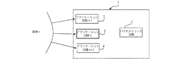
図1〜4は、本発明による自己適応型カードの原理を概略的に示すものであり、ここで、チップカード1は、一方で、一連のアプリケーション回路2〜4を含み、そして、他方で、バイオメトリック回路5を含むものであると区別することができる。
1 to 4 schematically show the principle of a self-adaptive card according to the invention, wherein the chip card 1 on the one hand comprises a series of
チップカード1は多数のアプリケーション回路を含むことができ、それらのうちの3つのみを図中に示す。参照番号2〜4は、アプリケーション回路n−1、アプリケーション回路n及びアプリケーション回路n+1をそれぞれ表す。アプリケーション回路は、アプリケーションサービスに関連しているトランシーバーからなることができる。各アプリケーション回路は、カードが位置している環境を特徴付ける任意の物理現象に対して敏感である。これらの物理現象としては、熱、触覚(接触)、光、嗅覚、音、圧力、電磁場などを挙げることができる。カードが「n」環境内にある場合、アプリケーション回路nは、そこへ直接関連している前記環境の存在を検出するが、相当するアプリケーションサービスnをアクティブ化しない。このアプリケーションサービスは、特定のプログラムの実行、又は、前記環境「n」を伴う交換プロトコルであることができる。
The chip card 1 can include a number of application circuits, only three of which are shown in the figure.
その他のアプリケーション回路n−1及びアプリケーション回路n+1は、無反応のままにしておく、すなわち、環境「n」はこれらのアプリケーション回路によって認識されない。 The other application circuit n-1 and application circuit n + 1 are left unresponsive, i.e. the environment "n" is not recognized by these application circuits.
次に、図2において見られるように、オーソリゼーションリクエストをバイオメトリック回路5へ送信する。前記オーソリゼーションリクエストを受けて、バイオメトリック回路は、カードユーザーを認識及び同定するための認証プロセスを開始する。このために、バイオメトリック回路は、物理特性の分析(指紋、虹彩イメージング、網膜イメージングなど)、行動解析(声の分析、署名など)などによる種々のタイプであることができるバイオメトリックセンサーを含む。
Next, as seen in FIG. 2, an authorization request is sent to the
ユーザーは、次に、バイオメトリック検出を受けることが必要であり、その結果、バイオメトリック回路は、カード内に含まれるデータと次に比較されるデータを回復する。比較が満足のいくものである場合には、図3において見られるように、生体認識はポシティブであり、そして、アグリーメント信号が送信されてアプリケーションサービスnがアクティブ化される。アプリケーションサービスがアクティブ化されると、図4において見られるように、アプリケーション回路nは環境と相互作用することができる。 The user then needs to undergo biometric detection, so that the biometric circuit recovers the data that is then compared with the data contained within the card. If the comparison is satisfactory, as seen in FIG. 3, biometric recognition is positive and an agreement signal is sent to activate application service n. When the application service is activated, application circuit n can interact with the environment, as seen in FIG.
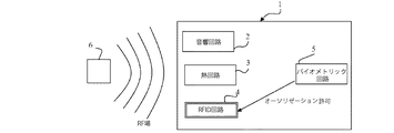
本発明によるデバイスの模範的な実施態様を図5〜8中に見ることができる。カードは、参照番号1によって表されている。アプリケーション回路2〜4は、それぞれ、音響回路、熱回路及びRFID回路である。
Exemplary embodiments of devices according to the present invention can be seen in FIGS. The card is represented by reference number 1. The
この模範的な実施態様では、チップカード1に対して電磁場又はRF場を生じさせるRFIDリーダー6によって環境が表されている。RFID回路は、このRF場を検出し、そして、図6では、バイオメトリック回路5へオーソリゼーションリクエストを送信する。このオーソリゼーションリクエストの目的は、RFID回路4とRFIDリーダー6との間のRFID通信サービスをアクティブ化するためである。バイオメトリック回路5はユーザーを認証し、次に、アグリーメント信号又はディスアグリーメント信号をRFID回路へ送信する。例えば、図7に表されるようなアグリーメントの場合は、図8に示されるように、RFID回路が通信サービスをアクティブ化し、前記サービスは、特に、データ又は指示をRFIDリーダー6へ伝達することができる。RFIDリーダー6は、ゲート、スロットマシーン又は任意のその他のシステムと関連することができ、その結果、チップカードからの指示の受領によって、ゲートを開くこと、スロットマシーンのアクティブ化、システムのスタンドバイ又はスイッチをいれることなどを生じさせることができる。
In this exemplary embodiment, the environment is represented by an
指示は、暗号化されている又はされていないRFIDリーダー6を対象とした指示及びユーザーの個人データを含むことができる。
The instructions may include instructions directed to the
或るアプリケーション回路によって検出される環境信号は、例えば、いくつかのアプリケーションサービスがこのアプリケーション回路を介してアクティブ化される可能性が高い場合に、特に、どのアプリケーションサービスをアクティブ化する必要があるかを見分けるための、暗号化されている又はされていない信号であることができる。 Environmental signals detected by an application circuit, for example, which application services need to be activated, especially when some application services are likely to be activated through this application circuit It can be an encrypted or unencrypted signal to distinguish.
例えば、特にリアルタイムで、ユーザーにより獲得された収益を回収するために、又は、スロットマシーンにおけるユーザーのアカウントに入金するために、アクティブ化されたアプリケーションサービスが、RF場を介してスロットマシーンと通信を開始することを見込むことができる。 For example, an activated application service communicates with the slot machine via the RF field, particularly in real time, to collect revenue earned by the user or to credit the user's account at the slot machine. You can expect to start.
図9は、本発明による模範的なチップカードの単純化されたブロック図である。1つのアプリケーションサービスA1と関連している音響トランシーバー7を見分けることができる。熱トランシーバー8は、1つのアプリケーションサービスA2と関連している。RFIDトランシーバー9は、1つのアプリケーションサービスA3と関連している。トランシーバーがいくつかのアプリケーションサービスと関連している、より複雑なシステムを見込むこともできる。いくつかのトランシーバーにより同時に検出されたいくつかの励起信号を使用して、進行中の環境のための適当なアプリケーションを決定することも更に可能である。 FIG. 9 is a simplified block diagram of an exemplary chip card according to the present invention. The acoustic transceiver 7 associated with one application service A1 can be identified. The thermal transceiver 8 is associated with one application service A2. The RFID transceiver 9 is associated with one application service A3. You can also expect more complex systems where the transceiver is associated with several application services. It is further possible to use several excitation signals detected simultaneously by several transceivers to determine the appropriate application for the ongoing environment.
図9に示されるように、トランシーバーとそれに関連するアプリケーションサービスとの間の各リンクにおいて、制御スイッチ11,12,13をそれぞれ導入して、関連した制御スイッチをオンにする場合にだけアプリケーションサービスがアクティブ化されるようにする。
As shown in FIG. 9, in each link between a transceiver and its associated application service, an application service is only provided if a
図9において、各トランシーバー7,8,9は、チップカード1の全てのコンポーネント及びソフトウェアプログラムを管理する制御ユニット10と接続している。制御ユニット10は:
− それ自身の作動のためであって、バイオメトリック回路5を制御するためのソフトウェアアプリケーションを含むフラッシュメモリー;
− RAMメモリー;
− クロック;及び
− いくつかの入力装置/出力装置;
を備えている、マイクロコントローラーである。
In FIG. 9, each transceiver 7, 8, 9 is connected to a
A flash memory for its own operation and including a software application for controlling the
-RAM memory;
-A clock; and-several input / output devices;
It is a microcontroller equipped with.
制御ユニット10は、カード中に内蔵されているチップの形態であり、そして、低い消費量を有する。制御ユニット10は、バイオメトリック回路5により放出されたアクティブ化アグリーメントに応えてスイッチ11,12,13のうちの1つをオンにするように構成される。
The
ヒューマン・マシン・インターフェースHMI17は、表示手段、入力手段、音声的及び視覚的送信手段を含む。視覚的送信は発光ダイオードLEDを介して実施することができる。内蔵バッテリー16は、カード1の全てのコンポートメントに動力を供給する。
The human
バイオメトリック回路5は、未加工のバイオメトリックデータの入力に対応するバイオメトリックセンサー14を含む。指紋センサーを使用する。バイオメトリック回路5は、バイオメトリックデータを処理して指紋の比較及び記録を実行することのできる計算ユニット15も含む。
The
記録は、以下の方法:
− ユーザーが制御回路を介してカードをアクティブ化する;
− 制御回路が、バイオメトリック回路を「記録」モードにすることによって、前記バイオメトリック回路をアクティブ化する;
− ユーザーが彼/彼女の指を指紋センサーに置いて、前記指紋センサーが相当する情報を計算ユニットへ送信する;及び
− 前記情報が送信され、次に計算ユニット内に保存される場合、HMIインターフェースを介して、記録が無事に実行されたことを制御ユニットがユーザーに知らせる;
によって行われる。
Record the following methods:
-The user activates the card via the control circuit;
The control circuit activates the biometric circuit by placing the biometric circuit in a “record” mode;
-The user places his / her finger on the fingerprint sensor and the fingerprint sensor sends the corresponding information to the computing unit; and-the HMI interface if the information is sent and then stored in the computing unit Via the control unit informs the user that the recording has been successfully performed;
Is done by.
カードの操作を以下のようにすることができる。励起信号がトランシーバー7,8,9のうちの1つ、例えば、トランシーバー7により検出される場合、制御ユニット10は認証プロセスをアクティブ化及び開始する:
− 制御回路が、バイオメトリック回路を「認証」モードにすることによって、前記バイオメトリック回路をアクティブ化する;
− ユーザーが彼/彼女の指を指紋センサーに置いて、前記指紋センサーが相当する情報を計算ユニットへ送信する;
− 計算ユニットは、前記情報を記録段階の間に既に保存されている情報と比較する;及び
− 認証後、制御ユニットはユーザーに結果を知らせて、バイオメトリック回路を非アクティブ化する。
The card can be operated as follows. If the excitation signal is detected by one of the transceivers 7, 8, 9 eg the transceiver 7, the
The control circuit activates the biometric circuit by placing the biometric circuit in an “authentication” mode;
The user places his / her finger on the fingerprint sensor and the fingerprint sensor sends the corresponding information to the calculation unit;
The calculation unit compares the information with the information already stored during the recording phase; and-after authentication, the control unit informs the user of the result and deactivates the biometric circuit.
ポジティブな応答(認証の成功)の場合には、制御ユニットは、次に、スイッチ11をオンにして、アプリケーションサービスA1がトランシーバー7を介して外部環境と通信することを可能にする。もちろん、制御スイッチ11,12,13をソフトウェアの形態にして、認証アグリーメントの受領後にアプリケーションサービスへのアクセスを達成することもできる。 In the case of a positive response (authentication success), the control unit then turns on the switch 11 to allow the application service A1 to communicate with the external environment via the transceiver 7. Of course, the control switches 11, 12, 13 can be in the form of software to achieve access to the application service after receipt of the authentication agreement.
もちろん、本発明は、前述の実施例に限定されるものではなく、そして、これらの実施例に対して本発明の範囲から逸脱することなく種々の変更を行うことができる。本発明のデバイスは、例えば:
− 銀行分野;
− 個人識別;
− ゲーム分野;
− ドアを開けるためのデジタルキー;
− メッセージの記録/読み上げ分野;
− データ回復;及び
− 例えば、血液又はDNA試験用の医療分野;
の種々の分野に適用することができる。
Of course, the present invention is not limited to the above-described embodiments, and various modifications can be made to these embodiments without departing from the scope of the present invention. The device of the present invention is, for example:
-Banking sector;
-Personal identification;
-Game area;
-A digital key to open the door;
-Message recording / reading field;
-Data recovery; and-for example, the medical field for blood or DNA testing;
It can be applied to various fields.
Claims (11)
前記の励起されたアプリケーション回路、前記関連サービスを同定することが可能であり、そして、アクティブ化オーソリゼーションに応えて前記サービスをアクティブ化することが可能である、制御ユニットと;
前記アクティブ化オーソリゼーションを生じさせるためにユーザーを認証するバイオメトリック回路と;
を含む保護通信デバイス。 A plurality of application circuits, each application circuit being associated with at least one application service securely contained within the device and capable of being excited by an external signal When;
A control unit capable of identifying the excited application circuit, the associated service, and activating the service in response to an activation authorization;
A biometric circuit for authenticating a user to cause the activation authorization;
Including protection communication device.
− 音響検出器;
− 熱検出器;
− オルファクトル ディテクター;
− 光検出器;
− 圧力検出器;及び
− 加速度計;
のうちの少なくとも1つを含むことを特徴とする、請求項1〜4のいずれか一項に記載のデバイス。 The application circuit has the following elements:
-Acoustic detectors;
-Heat detectors;
-An olfactor detector;
-Photodetectors;
-A pressure detector; and-an accelerometer;
The device according to claim 1, comprising at least one of the following:
カード内に安全に含まれる少なくとも1つの前記アプリケーションサービスに各々が関連している前記アプリケーション回路の1つによって、励起外部信号を検出する工程と;
前記制御ユニット内で、前記の励起されたアプリケーション回路と、この励起されたアプリケーション回路に関連する前記アプリケーションサービスとを同定し、前記バイオメトリック回路内のバイオメトリック比較によって認証プロセスを開始し、そして、次に、前記の励起されたアプリケーション回路を、前記バイオメトリック回路からのアクティブ化オーソリゼーションに応えてアクティブ化する工程と;
を含む、前記方法。 A method performed in a protected communication card including a plurality of application circuits, a control unit and a biometric circuit, comprising the following steps:
Detecting an excitation external signal by one of the application circuits each associated with at least one of the application services securely contained within a card;
Identifying the excited application circuit and the application service associated with the excited application circuit within the control unit, initiating an authentication process by a biometric comparison within the biometric circuit; and Then activating the excited application circuit in response to an activation authorization from the biometric circuit;
Said method.
Applications Claiming Priority (3)
| Application Number | Priority Date | Filing Date | Title |
|---|---|---|---|
| FR0959414A FR2954546B1 (en) | 2009-12-22 | 2009-12-22 | "MULTI-APPLICATION CHIP CARD WITH BIOMETRIC VALIDATION." |
| FR0959414 | 2009-12-22 | ||
| PCT/FR2010/052767 WO2011083241A1 (en) | 2009-12-22 | 2010-12-16 | Multiple application chip card having biometric validation |
Related Child Applications (1)
| Application Number | Title | Priority Date | Filing Date |
|---|---|---|---|
| JP2015148741A Division JP2015215918A (en) | 2009-12-22 | 2015-07-28 | Multiple application chip card having biometric validation |
Publications (2)
| Publication Number | Publication Date |
|---|---|
| JP2013515310A true JP2013515310A (en) | 2013-05-02 |
| JP2013515310A5 JP2013515310A5 (en) | 2014-12-04 |
Family
ID=42333264
Family Applications (4)
| Application Number | Title | Priority Date | Filing Date |
|---|---|---|---|
| JP2012545379A Pending JP2013515310A (en) | 2009-12-22 | 2010-12-16 | Multiple application chip card with biometric authentication |
| JP2015148741A Pending JP2015215918A (en) | 2009-12-22 | 2015-07-28 | Multiple application chip card having biometric validation |
| JP2018080823A Active JP6876651B2 (en) | 2009-12-22 | 2018-04-19 | Multiple application chip card with biometrics |
| JP2020129855A Withdrawn JP2020194563A (en) | 2009-12-22 | 2020-07-31 | Multiple application chip card with biometric authentication |
Family Applications After (3)
| Application Number | Title | Priority Date | Filing Date |
|---|---|---|---|
| JP2015148741A Pending JP2015215918A (en) | 2009-12-22 | 2015-07-28 | Multiple application chip card having biometric validation |
| JP2018080823A Active JP6876651B2 (en) | 2009-12-22 | 2018-04-19 | Multiple application chip card with biometrics |
| JP2020129855A Withdrawn JP2020194563A (en) | 2009-12-22 | 2020-07-31 | Multiple application chip card with biometric authentication |
Country Status (22)
| Country | Link |
|---|---|
| US (1) | US9361441B2 (en) |
| EP (1) | EP2517141B1 (en) |
| JP (4) | JP2013515310A (en) |
| CN (1) | CN102834829B (en) |
| BR (1) | BR112012015667A2 (en) |
| CA (1) | CA2784739C (en) |
| CY (1) | CY1123335T1 (en) |
| DK (1) | DK2517141T3 (en) |
| ES (1) | ES2817795T3 (en) |
| FR (1) | FR2954546B1 (en) |
| HR (1) | HRP20201498T1 (en) |
| HU (1) | HUE050848T2 (en) |
| IL (1) | IL220370A (en) |
| LT (1) | LT2517141T (en) |
| MA (1) | MA33891B1 (en) |
| PL (1) | PL2517141T3 (en) |
| PT (1) | PT2517141T (en) |
| RS (1) | RS60831B1 (en) |
| SI (1) | SI2517141T1 (en) |
| TN (1) | TN2012000298A1 (en) |
| WO (1) | WO2011083241A1 (en) |
| ZA (1) | ZA201204594B (en) |
Cited By (1)
| Publication number | Priority date | Publication date | Assignee | Title |
|---|---|---|---|---|
| JP2019536141A (en) * | 2016-10-24 | 2019-12-12 | ローベルト ボツシユ ゲゼルシヤフト ミツト ベシユレンクテル ハフツングRobert Bosch Gmbh | Communication device for wireless communication and method for controlling such a communication device |
Families Citing this family (12)
| Publication number | Priority date | Publication date | Assignee | Title |
|---|---|---|---|---|
| WO2014171989A1 (en) * | 2013-01-29 | 2014-10-23 | Grace Mary | Smart card and smart card system with enhanced security features |
| EP2782035B1 (en) * | 2013-03-19 | 2021-06-09 | Nxp B.V. | Smartcard, smartcard system and method for configuring a smartcard |
| WO2017037913A1 (en) * | 2015-09-03 | 2017-03-09 | ブレイニー株式会社 | Multifunction card, card payment terminal, and card payment system |
| GB201602371D0 (en) * | 2016-02-10 | 2016-03-23 | Zwipe As | Smartcard and method for controlling a smartcard |
| KR101813888B1 (en) * | 2017-04-03 | 2018-01-04 | 주식회사 올아이티탑 | System of certification card checking fingerprint and sensing a henatocele of finger |
| WO2018088865A2 (en) * | 2016-11-14 | 2018-05-17 | 주식회사 올아이티탑 | Fusion card for exhibiting photograph information by flexible display interworking with fingerprint recognition and authentication method thereby |
| KR101852154B1 (en) * | 2017-07-18 | 2018-06-05 | 주식회사 올아이티탑 | Certification card checking fingerprint |
| US11157908B2 (en) | 2017-07-14 | 2021-10-26 | The Toronto-Dominion Bank | Smart chip card with fraud alert and biometric reset |
| KR101822901B1 (en) * | 2017-09-29 | 2018-03-15 | 주식회사 올아이티탑 | System and method of certification card checking fingerprint and sensing a henatocele of finger |
| US10460748B2 (en) | 2017-10-04 | 2019-10-29 | The Toronto-Dominion Bank | Conversational interface determining lexical personality score for response generation with synonym replacement |
| US10339931B2 (en) | 2017-10-04 | 2019-07-02 | The Toronto-Dominion Bank | Persona-based conversational interface personalization using social network preferences |
| TWI734302B (en) | 2019-12-16 | 2021-07-21 | 義隆電子股份有限公司 | Smart card and control method thereof |
Citations (6)
| Publication number | Priority date | Publication date | Assignee | Title |
|---|---|---|---|---|
| JP2003044801A (en) * | 2001-07-27 | 2003-02-14 | Dainippon Printing Co Ltd | Portable information processor provided with a plurality of information transmitting means |
| JP2003346107A (en) * | 2002-05-27 | 2003-12-05 | Totoku Electric Co Ltd | Wireless article management tag and article management system |
| JP2005316724A (en) * | 2004-04-28 | 2005-11-10 | Matsushita Electric Works Ltd | Active rfid tag |
| JP2006039789A (en) * | 2004-07-26 | 2006-02-09 | Dainippon Printing Co Ltd | Non-contact data carrier with temperature change detecting function |
| JP2006235687A (en) * | 2005-02-22 | 2006-09-07 | Seiko Epson Corp | Personal digital assistant |
| JP2009031877A (en) * | 2007-07-24 | 2009-02-12 | Nec Access Technica Ltd | Contactless ic card, portable terminal equipment, start control method, and start control program |
Family Cites Families (27)
| Publication number | Priority date | Publication date | Assignee | Title |
|---|---|---|---|---|
| JPH05258127A (en) * | 1992-03-12 | 1993-10-08 | Mitsubishi Electric Corp | Information card |
| US8135413B2 (en) * | 1998-11-24 | 2012-03-13 | Tracbeam Llc | Platform and applications for wireless location and other complex services |
| US7070112B2 (en) * | 1999-09-07 | 2006-07-04 | American Express Travel Related Services Company, Inc. | Transparent transaction device |
| US6698653B1 (en) * | 1999-10-28 | 2004-03-02 | Mel Diamond | Identification method, especially for airport security and the like |
| US7536557B2 (en) * | 2001-03-22 | 2009-05-19 | Ensign Holdings | Method for biometric authentication through layering biometric traits |
| TWI246028B (en) * | 2001-06-28 | 2005-12-21 | Trek 2000 Int Ltd | A portable device having biometrics-based authentication capabilities |
| US8266451B2 (en) * | 2001-08-31 | 2012-09-11 | Gemalto Sa | Voice activated smart card |
| WO2003084124A1 (en) * | 2002-03-28 | 2003-10-09 | Innovation Connection Corporation | Apparatus and method for transactions security using biometric identity validation and contactless smartcard. |
| US20040111320A1 (en) * | 2002-12-05 | 2004-06-10 | Jorg Schlieffers | Electronic shopping system |
| JP2005293485A (en) * | 2004-04-05 | 2005-10-20 | Nippon Telegr & Teleph Corp <Ntt> | Ic tag |
| JP2005352907A (en) * | 2004-06-11 | 2005-12-22 | Ntt Docomo Inc | Mobile communication terminal and data access control method |
| JP2006012026A (en) * | 2004-06-29 | 2006-01-12 | Dainippon Printing Co Ltd | Mobile information storage medium and program therefor |
| JP4285368B2 (en) * | 2004-08-25 | 2009-06-24 | セイコーエプソン株式会社 | IC card, authentication system, and authentication method |
| US20070016940A1 (en) | 2005-07-08 | 2007-01-18 | Jdi Ventures, Inc. D/B/A Peak Performance Solutions | Identification and password management device |
| CN100421047C (en) * | 2005-07-22 | 2008-09-24 | 祥群科技股份有限公司 | Biological signal input device, computer system with said device and its control method |
| US20080282343A1 (en) * | 2005-11-09 | 2008-11-13 | Koninklijke Philips Electronics, N.V. | Digital Rights Management Using Biometric Data |
| EP1811421A1 (en) * | 2005-12-29 | 2007-07-25 | AXSionics AG | Security token and method for authentication of a user with the security token |
| EP2016539A4 (en) * | 2006-05-11 | 2010-06-09 | Singular Id Pte Ltd | Method of identifying an object, an identification tag, an object adapted to be identified, and related device and system |
| KR101239482B1 (en) * | 2007-03-23 | 2013-03-06 | 퀄컴 인코포레이티드 | Multi-sensor data collection and/or processing |
| US20090027162A1 (en) | 2007-07-23 | 2009-01-29 | Forster Ian J | Controllable rfid device, and method |
| TWI356312B (en) * | 2007-08-22 | 2012-01-11 | Univ Nat Taiwan | Methods and systems for tracking users and providi |
| WO2009064813A1 (en) * | 2007-11-12 | 2009-05-22 | Bally Gaming, Inc. | Networked gaming system including anonymous player biometric identification and tracking |
| US20100036268A1 (en) * | 2008-08-07 | 2010-02-11 | Searete Llc, A Limited Liability Corporation Of The State Of Delaware | Circulatory monitoring systems and methods |
| US8244211B2 (en) * | 2008-02-07 | 2012-08-14 | Inflexis Llc | Mobile electronic security apparatus and method |
| US20100149073A1 (en) * | 2008-11-02 | 2010-06-17 | David Chaum | Near to Eye Display System and Appliance |
| US9135594B2 (en) * | 2008-05-23 | 2015-09-15 | International Business Machines Corporation | Ambient project management |
| US20100056873A1 (en) * | 2008-08-27 | 2010-03-04 | Allen Paul G | Health-related signaling via wearable items |
-
2009
- 2009-12-22 FR FR0959414A patent/FR2954546B1/en active Active
-
2010
- 2010-12-16 LT LTEP10810772.3T patent/LT2517141T/en unknown
- 2010-12-16 PT PT108107723T patent/PT2517141T/en unknown
- 2010-12-16 DK DK10810772.3T patent/DK2517141T3/en active
- 2010-12-16 EP EP10810772.3A patent/EP2517141B1/en active Active
- 2010-12-16 PL PL10810772T patent/PL2517141T3/en unknown
- 2010-12-16 WO PCT/FR2010/052767 patent/WO2011083241A1/en active Application Filing
- 2010-12-16 BR BR112012015667A patent/BR112012015667A2/en not_active Application Discontinuation
- 2010-12-16 US US13/518,463 patent/US9361441B2/en active Active
- 2010-12-16 RS RS20201133A patent/RS60831B1/en unknown
- 2010-12-16 HU HUE10810772A patent/HUE050848T2/en unknown
- 2010-12-16 ES ES10810772T patent/ES2817795T3/en active Active
- 2010-12-16 MA MA34996A patent/MA33891B1/en unknown
- 2010-12-16 CA CA2784739A patent/CA2784739C/en active Active
- 2010-12-16 JP JP2012545379A patent/JP2013515310A/en active Pending
- 2010-12-16 CN CN201080059002.8A patent/CN102834829B/en active Active
- 2010-12-16 SI SI201032030T patent/SI2517141T1/en unknown
-
2012
- 2012-06-13 TN TNP2012000298A patent/TN2012000298A1/en unknown
- 2012-06-13 IL IL220370A patent/IL220370A/en active IP Right Grant
- 2012-06-20 ZA ZA2012/04594A patent/ZA201204594B/en unknown
-
2015
- 2015-07-28 JP JP2015148741A patent/JP2015215918A/en active Pending
-
2018
- 2018-04-19 JP JP2018080823A patent/JP6876651B2/en active Active
-
2020
- 2020-07-31 JP JP2020129855A patent/JP2020194563A/en not_active Withdrawn
- 2020-09-16 CY CY20201100876T patent/CY1123335T1/en unknown
- 2020-09-21 HR HRP20201498TT patent/HRP20201498T1/en unknown
Patent Citations (6)
| Publication number | Priority date | Publication date | Assignee | Title |
|---|---|---|---|---|
| JP2003044801A (en) * | 2001-07-27 | 2003-02-14 | Dainippon Printing Co Ltd | Portable information processor provided with a plurality of information transmitting means |
| JP2003346107A (en) * | 2002-05-27 | 2003-12-05 | Totoku Electric Co Ltd | Wireless article management tag and article management system |
| JP2005316724A (en) * | 2004-04-28 | 2005-11-10 | Matsushita Electric Works Ltd | Active rfid tag |
| JP2006039789A (en) * | 2004-07-26 | 2006-02-09 | Dainippon Printing Co Ltd | Non-contact data carrier with temperature change detecting function |
| JP2006235687A (en) * | 2005-02-22 | 2006-09-07 | Seiko Epson Corp | Personal digital assistant |
| JP2009031877A (en) * | 2007-07-24 | 2009-02-12 | Nec Access Technica Ltd | Contactless ic card, portable terminal equipment, start control method, and start control program |
Cited By (3)
| Publication number | Priority date | Publication date | Assignee | Title |
|---|---|---|---|---|
| JP2019536141A (en) * | 2016-10-24 | 2019-12-12 | ローベルト ボツシユ ゲゼルシヤフト ミツト ベシユレンクテル ハフツングRobert Bosch Gmbh | Communication device for wireless communication and method for controlling such a communication device |
| US11438028B2 (en) | 2016-10-24 | 2022-09-06 | Robert Bosch Gmbh | Communication set-up for wireless communication and method for controlling such a communication set-up |
| JP7160805B2 (en) | 2016-10-24 | 2022-10-25 | ローベルト ボツシユ ゲゼルシヤフト ミツト ベシユレンクテル ハフツング | Communication device for wireless communication and method of controlling such communication device |
Also Published As
| Publication number | Publication date |
|---|---|
| TN2012000298A1 (en) | 2013-12-12 |
| FR2954546B1 (en) | 2012-09-21 |
| FR2954546A1 (en) | 2011-06-24 |
| CN102834829A (en) | 2012-12-19 |
| IL220370A0 (en) | 2012-08-30 |
| JP2020194563A (en) | 2020-12-03 |
| JP2015215918A (en) | 2015-12-03 |
| CA2784739A1 (en) | 2011-07-14 |
| JP6876651B2 (en) | 2021-05-26 |
| US20120260319A1 (en) | 2012-10-11 |
| BR112012015667A2 (en) | 2023-10-10 |
| SI2517141T1 (en) | 2020-10-30 |
| ES2817795T3 (en) | 2021-04-08 |
| DK2517141T3 (en) | 2020-09-28 |
| RS60831B1 (en) | 2020-10-30 |
| EP2517141B1 (en) | 2020-06-24 |
| CA2784739C (en) | 2023-03-21 |
| PT2517141T (en) | 2020-09-24 |
| ZA201204594B (en) | 2013-02-27 |
| JP2018142348A (en) | 2018-09-13 |
| WO2011083241A1 (en) | 2011-07-14 |
| PL2517141T3 (en) | 2020-12-14 |
| HUE050848T2 (en) | 2021-01-28 |
| IL220370A (en) | 2017-10-31 |
| US9361441B2 (en) | 2016-06-07 |
| CN102834829B (en) | 2020-01-14 |
| HRP20201498T1 (en) | 2020-12-25 |
| EP2517141A1 (en) | 2012-10-31 |
| MA33891B1 (en) | 2013-01-02 |
| CY1123335T1 (en) | 2021-12-31 |
| LT2517141T (en) | 2020-10-12 |
Similar Documents
| Publication | Publication Date | Title |
|---|---|---|
| JP6876651B2 (en) | Multiple application chip card with biometrics | |
| US10922598B2 (en) | Fingerprint authorisable device | |
| JP6808850B2 (en) | Power operation method using fingerprint recognition card and fingerprint recognition card | |
| US8880055B1 (en) | Method and apparatus for using near field communication (NFC) to perform transactions on a mobile device | |
| JP4792405B2 (en) | Portable data carrier, external device, system and method for wireless data transfer | |
| US20150006378A1 (en) | User devices, systems and methods for use in transactions | |
| JP7026701B2 (en) | Smart card and smart card control method | |
| US8643475B1 (en) | Radio frequency identification secret handshakes | |
| KR102367791B1 (en) | Anti-Attack Biometric Authentication Device | |
| US20170228631A1 (en) | Smartcard and method for controlling a smartcard | |
| CN110415389B (en) | Gesture access control system and method for predicting location of mobile device relative to user | |
| US20150286922A1 (en) | Biometric identity verification system and method | |
| CN112368713A (en) | Biometric enrollment | |
| EP2795586A1 (en) | Method to perform a transaction using a biometric reader and associated biometric reader | |
| JP2006011614A (en) | Finger ring equipped with fingerprint recognition function, finger print recognition device and information processing system using them | |
| KR102425295B1 (en) | Fingerprint recognition card and method for operating power of the fingerprint recognition card | |
| JP2003132031A (en) | Data communication device | |
| TWI830784B (en) | Biometric enrolment | |
| CA3098049C (en) | Systems methods and devices for increasing security when using smartcards | |
| WO2015075490A2 (en) | Device for identification of individuals |
Legal Events
| Date | Code | Title | Description |
|---|---|---|---|
| A621 | Written request for application examination |
Free format text: JAPANESE INTERMEDIATE CODE: A621 Effective date: 20131031 |
|
| A977 | Report on retrieval |
Free format text: JAPANESE INTERMEDIATE CODE: A971007 Effective date: 20140411 |
|
| A131 | Notification of reasons for refusal |
Free format text: JAPANESE INTERMEDIATE CODE: A131 Effective date: 20140415 |
|
| A601 | Written request for extension of time |
Free format text: JAPANESE INTERMEDIATE CODE: A601 Effective date: 20140715 |
|
| A601 | Written request for extension of time |
Free format text: JAPANESE INTERMEDIATE CODE: A601 Effective date: 20140716 |
|
| A602 | Written permission of extension of time |
Free format text: JAPANESE INTERMEDIATE CODE: A602 Effective date: 20140723 |
|
| A602 | Written permission of extension of time |
Free format text: JAPANESE INTERMEDIATE CODE: A602 Effective date: 20140724 |
|
| A524 | Written submission of copy of amendment under article 19 pct |
Free format text: JAPANESE INTERMEDIATE CODE: A524 Effective date: 20141015 |
|
| A02 | Decision of refusal |
Free format text: JAPANESE INTERMEDIATE CODE: A02 Effective date: 20150331 |