JP2012175855A - Area energy management system, and area energy integrated management apparatus and area energy integrated management method used therefor - Google Patents
Area energy management system, and area energy integrated management apparatus and area energy integrated management method used therefor Download PDFInfo
- Publication number
- JP2012175855A JP2012175855A JP2011037003A JP2011037003A JP2012175855A JP 2012175855 A JP2012175855 A JP 2012175855A JP 2011037003 A JP2011037003 A JP 2011037003A JP 2011037003 A JP2011037003 A JP 2011037003A JP 2012175855 A JP2012175855 A JP 2012175855A
- Authority
- JP
- Japan
- Prior art keywords
- energy
- building
- management information
- energy management
- regional
- Prior art date
- Legal status (The legal status is an assumption and is not a legal conclusion. Google has not performed a legal analysis and makes no representation as to the accuracy of the status listed.)
- Pending
Links
- 238000007726 management method Methods 0.000 title claims abstract description 243
- 230000005540 biological transmission Effects 0.000 claims abstract description 16
- 238000004146 energy storage Methods 0.000 claims description 40
- 230000009467 reduction Effects 0.000 claims description 31
- 230000007812 deficiency Effects 0.000 abstract 1
- 238000005259 measurement Methods 0.000 description 15
- XLYOFNOQVPJJNP-UHFFFAOYSA-N water Substances O XLYOFNOQVPJJNP-UHFFFAOYSA-N 0.000 description 10
- 238000010248 power generation Methods 0.000 description 7
- 238000009529 body temperature measurement Methods 0.000 description 6
- 238000010586 diagram Methods 0.000 description 6
- 238000000034 method Methods 0.000 description 5
- 238000012545 processing Methods 0.000 description 5
- 230000004044 response Effects 0.000 description 3
- 230000000694 effects Effects 0.000 description 2
- 230000005611 electricity Effects 0.000 description 2
- 238000005338 heat storage Methods 0.000 description 2
- 238000005381 potential energy Methods 0.000 description 2
- 230000008569 process Effects 0.000 description 2
- 238000009825 accumulation Methods 0.000 description 1
- 238000004378 air conditioning Methods 0.000 description 1
- 238000005265 energy consumption Methods 0.000 description 1
- 238000005516 engineering process Methods 0.000 description 1
- 238000010438 heat treatment Methods 0.000 description 1
- 238000009434 installation Methods 0.000 description 1
- 230000007246 mechanism Effects 0.000 description 1
- 238000012986 modification Methods 0.000 description 1
- 230000004048 modification Effects 0.000 description 1
- 238000012544 monitoring process Methods 0.000 description 1
- 238000012827 research and development Methods 0.000 description 1
Images


Classifications
-
- H—ELECTRICITY
- H02—GENERATION; CONVERSION OR DISTRIBUTION OF ELECTRIC POWER
- H02J—CIRCUIT ARRANGEMENTS OR SYSTEMS FOR SUPPLYING OR DISTRIBUTING ELECTRIC POWER; SYSTEMS FOR STORING ELECTRIC ENERGY
- H02J3/00—Circuit arrangements for ac mains or ac distribution networks
- H02J3/004—Generation forecast, e.g. methods or systems for forecasting future energy generation
-
- H—ELECTRICITY
- H02—GENERATION; CONVERSION OR DISTRIBUTION OF ELECTRIC POWER
- H02J—CIRCUIT ARRANGEMENTS OR SYSTEMS FOR SUPPLYING OR DISTRIBUTING ELECTRIC POWER; SYSTEMS FOR STORING ELECTRIC ENERGY
- H02J13/00—Circuit arrangements for providing remote indication of network conditions, e.g. an instantaneous record of the open or closed condition of each circuitbreaker in the network; Circuit arrangements for providing remote control of switching means in a power distribution network, e.g. switching in and out of current consumers by using a pulse code signal carried by the network
- H02J13/00002—Circuit arrangements for providing remote indication of network conditions, e.g. an instantaneous record of the open or closed condition of each circuitbreaker in the network; Circuit arrangements for providing remote control of switching means in a power distribution network, e.g. switching in and out of current consumers by using a pulse code signal carried by the network characterised by monitoring
-
- H—ELECTRICITY
- H02—GENERATION; CONVERSION OR DISTRIBUTION OF ELECTRIC POWER
- H02J—CIRCUIT ARRANGEMENTS OR SYSTEMS FOR SUPPLYING OR DISTRIBUTING ELECTRIC POWER; SYSTEMS FOR STORING ELECTRIC ENERGY
- H02J13/00—Circuit arrangements for providing remote indication of network conditions, e.g. an instantaneous record of the open or closed condition of each circuitbreaker in the network; Circuit arrangements for providing remote control of switching means in a power distribution network, e.g. switching in and out of current consumers by using a pulse code signal carried by the network
- H02J13/00004—Circuit arrangements for providing remote indication of network conditions, e.g. an instantaneous record of the open or closed condition of each circuitbreaker in the network; Circuit arrangements for providing remote control of switching means in a power distribution network, e.g. switching in and out of current consumers by using a pulse code signal carried by the network characterised by the power network being locally controlled
-
- H—ELECTRICITY
- H02—GENERATION; CONVERSION OR DISTRIBUTION OF ELECTRIC POWER
- H02J—CIRCUIT ARRANGEMENTS OR SYSTEMS FOR SUPPLYING OR DISTRIBUTING ELECTRIC POWER; SYSTEMS FOR STORING ELECTRIC ENERGY
- H02J3/00—Circuit arrangements for ac mains or ac distribution networks
- H02J3/12—Circuit arrangements for ac mains or ac distribution networks for adjusting voltage in ac networks by changing a characteristic of the network load
- H02J3/14—Circuit arrangements for ac mains or ac distribution networks for adjusting voltage in ac networks by changing a characteristic of the network load by switching loads on to, or off from, network, e.g. progressively balanced loading
-
- H—ELECTRICITY
- H02—GENERATION; CONVERSION OR DISTRIBUTION OF ELECTRIC POWER
- H02J—CIRCUIT ARRANGEMENTS OR SYSTEMS FOR SUPPLYING OR DISTRIBUTING ELECTRIC POWER; SYSTEMS FOR STORING ELECTRIC ENERGY
- H02J3/00—Circuit arrangements for ac mains or ac distribution networks
- H02J3/28—Arrangements for balancing of the load in a network by storage of energy
-
- H—ELECTRICITY
- H02—GENERATION; CONVERSION OR DISTRIBUTION OF ELECTRIC POWER
- H02J—CIRCUIT ARRANGEMENTS OR SYSTEMS FOR SUPPLYING OR DISTRIBUTING ELECTRIC POWER; SYSTEMS FOR STORING ELECTRIC ENERGY
- H02J3/00—Circuit arrangements for ac mains or ac distribution networks
- H02J3/38—Arrangements for parallely feeding a single network by two or more generators, converters or transformers
- H02J3/381—Dispersed generators
-
- H—ELECTRICITY
- H02—GENERATION; CONVERSION OR DISTRIBUTION OF ELECTRIC POWER
- H02J—CIRCUIT ARRANGEMENTS OR SYSTEMS FOR SUPPLYING OR DISTRIBUTING ELECTRIC POWER; SYSTEMS FOR STORING ELECTRIC ENERGY
- H02J2310/00—The network for supplying or distributing electric power characterised by its spatial reach or by the load
- H02J2310/10—The network having a local or delimited stationary reach
- H02J2310/12—The local stationary network supplying a household or a building
- H02J2310/14—The load or loads being home appliances
-
- H—ELECTRICITY
- H02—GENERATION; CONVERSION OR DISTRIBUTION OF ELECTRIC POWER
- H02J—CIRCUIT ARRANGEMENTS OR SYSTEMS FOR SUPPLYING OR DISTRIBUTING ELECTRIC POWER; SYSTEMS FOR STORING ELECTRIC ENERGY
- H02J2310/00—The network for supplying or distributing electric power characterised by its spatial reach or by the load
- H02J2310/50—The network for supplying or distributing electric power characterised by its spatial reach or by the load for selectively controlling the operation of the loads
- H02J2310/56—The network for supplying or distributing electric power characterised by its spatial reach or by the load for selectively controlling the operation of the loads characterised by the condition upon which the selective controlling is based
- H02J2310/58—The condition being electrical
- H02J2310/60—Limiting power consumption in the network or in one section of the network, e.g. load shedding or peak shaving
-
- Y—GENERAL TAGGING OF NEW TECHNOLOGICAL DEVELOPMENTS; GENERAL TAGGING OF CROSS-SECTIONAL TECHNOLOGIES SPANNING OVER SEVERAL SECTIONS OF THE IPC; TECHNICAL SUBJECTS COVERED BY FORMER USPC CROSS-REFERENCE ART COLLECTIONS [XRACs] AND DIGESTS
- Y02—TECHNOLOGIES OR APPLICATIONS FOR MITIGATION OR ADAPTATION AGAINST CLIMATE CHANGE
- Y02A—TECHNOLOGIES FOR ADAPTATION TO CLIMATE CHANGE
- Y02A30/00—Adapting or protecting infrastructure or their operation
- Y02A30/60—Planning or developing urban green infrastructure
-
- Y—GENERAL TAGGING OF NEW TECHNOLOGICAL DEVELOPMENTS; GENERAL TAGGING OF CROSS-SECTIONAL TECHNOLOGIES SPANNING OVER SEVERAL SECTIONS OF THE IPC; TECHNICAL SUBJECTS COVERED BY FORMER USPC CROSS-REFERENCE ART COLLECTIONS [XRACs] AND DIGESTS
- Y02—TECHNOLOGIES OR APPLICATIONS FOR MITIGATION OR ADAPTATION AGAINST CLIMATE CHANGE
- Y02B—CLIMATE CHANGE MITIGATION TECHNOLOGIES RELATED TO BUILDINGS, e.g. HOUSING, HOUSE APPLIANCES OR RELATED END-USER APPLICATIONS
- Y02B70/00—Technologies for an efficient end-user side electric power management and consumption
- Y02B70/30—Systems integrating technologies related to power network operation and communication or information technologies for improving the carbon footprint of the management of residential or tertiary loads, i.e. smart grids as climate change mitigation technology in the buildings sector, including also the last stages of power distribution and the control, monitoring or operating management systems at local level
- Y02B70/3225—Demand response systems, e.g. load shedding, peak shaving
-
- Y—GENERAL TAGGING OF NEW TECHNOLOGICAL DEVELOPMENTS; GENERAL TAGGING OF CROSS-SECTIONAL TECHNOLOGIES SPANNING OVER SEVERAL SECTIONS OF THE IPC; TECHNICAL SUBJECTS COVERED BY FORMER USPC CROSS-REFERENCE ART COLLECTIONS [XRACs] AND DIGESTS
- Y02—TECHNOLOGIES OR APPLICATIONS FOR MITIGATION OR ADAPTATION AGAINST CLIMATE CHANGE
- Y02B—CLIMATE CHANGE MITIGATION TECHNOLOGIES RELATED TO BUILDINGS, e.g. HOUSING, HOUSE APPLIANCES OR RELATED END-USER APPLICATIONS
- Y02B90/00—Enabling technologies or technologies with a potential or indirect contribution to GHG emissions mitigation
- Y02B90/20—Smart grids as enabling technology in buildings sector
-
- Y—GENERAL TAGGING OF NEW TECHNOLOGICAL DEVELOPMENTS; GENERAL TAGGING OF CROSS-SECTIONAL TECHNOLOGIES SPANNING OVER SEVERAL SECTIONS OF THE IPC; TECHNICAL SUBJECTS COVERED BY FORMER USPC CROSS-REFERENCE ART COLLECTIONS [XRACs] AND DIGESTS
- Y04—INFORMATION OR COMMUNICATION TECHNOLOGIES HAVING AN IMPACT ON OTHER TECHNOLOGY AREAS
- Y04S—SYSTEMS INTEGRATING TECHNOLOGIES RELATED TO POWER NETWORK OPERATION, COMMUNICATION OR INFORMATION TECHNOLOGIES FOR IMPROVING THE ELECTRICAL POWER GENERATION, TRANSMISSION, DISTRIBUTION, MANAGEMENT OR USAGE, i.e. SMART GRIDS
- Y04S20/00—Management or operation of end-user stationary applications or the last stages of power distribution; Controlling, monitoring or operating thereof
- Y04S20/12—Energy storage units, uninterruptible power supply [UPS] systems or standby or emergency generators, e.g. in the last power distribution stages
-
- Y—GENERAL TAGGING OF NEW TECHNOLOGICAL DEVELOPMENTS; GENERAL TAGGING OF CROSS-SECTIONAL TECHNOLOGIES SPANNING OVER SEVERAL SECTIONS OF THE IPC; TECHNICAL SUBJECTS COVERED BY FORMER USPC CROSS-REFERENCE ART COLLECTIONS [XRACs] AND DIGESTS
- Y04—INFORMATION OR COMMUNICATION TECHNOLOGIES HAVING AN IMPACT ON OTHER TECHNOLOGY AREAS
- Y04S—SYSTEMS INTEGRATING TECHNOLOGIES RELATED TO POWER NETWORK OPERATION, COMMUNICATION OR INFORMATION TECHNOLOGIES FOR IMPROVING THE ELECTRICAL POWER GENERATION, TRANSMISSION, DISTRIBUTION, MANAGEMENT OR USAGE, i.e. SMART GRIDS
- Y04S20/00—Management or operation of end-user stationary applications or the last stages of power distribution; Controlling, monitoring or operating thereof
- Y04S20/20—End-user application control systems
- Y04S20/222—Demand response systems, e.g. load shedding, peak shaving
-
- Y—GENERAL TAGGING OF NEW TECHNOLOGICAL DEVELOPMENTS; GENERAL TAGGING OF CROSS-SECTIONAL TECHNOLOGIES SPANNING OVER SEVERAL SECTIONS OF THE IPC; TECHNICAL SUBJECTS COVERED BY FORMER USPC CROSS-REFERENCE ART COLLECTIONS [XRACs] AND DIGESTS
- Y04—INFORMATION OR COMMUNICATION TECHNOLOGIES HAVING AN IMPACT ON OTHER TECHNOLOGY AREAS
- Y04S—SYSTEMS INTEGRATING TECHNOLOGIES RELATED TO POWER NETWORK OPERATION, COMMUNICATION OR INFORMATION TECHNOLOGIES FOR IMPROVING THE ELECTRICAL POWER GENERATION, TRANSMISSION, DISTRIBUTION, MANAGEMENT OR USAGE, i.e. SMART GRIDS
- Y04S20/00—Management or operation of end-user stationary applications or the last stages of power distribution; Controlling, monitoring or operating thereof
- Y04S20/20—End-user application control systems
- Y04S20/242—Home appliances
Abstract
Description
本発明の実施形態は、地域エネルギー管理システムおよびこれに利用する地域エネルギー統合管理装置、地域エネルギー統合管理方法に関する。 Embodiments described herein relate generally to a regional energy management system, a regional energy integrated management apparatus, and a regional energy integrated management method used therefor.
従来、オフィス建物や工場等の建物においては、電力や熱などのエネルギーの運用効率を適正化するために、BAS(Building Automation Systems;建物管理システム)やBEMS(Building and Energy Management System;建物エネルギーマネジメントシステム)等を利用したエネルギー管理システムが提案されている。 Conventionally, in buildings such as office buildings and factories, BAS (Building Automation Systems) and BEMS (Building and Energy Management Systems) are used to optimize the operational efficiency of energy such as electric power and heat. An energy management system using a system) has been proposed.
これらのエネルギー管理システムには、風力発電や太陽光発電などにより供給される再生可能エネルギーやエネルギー蓄積装置などにより供給されるエネルギーを基幹電力と併用することで、発電と電力消費のマッチングをとる需給制御技術も含まれている。 These energy management systems use renewable energy supplied by wind power generation, solar power generation, etc., and energy supplied by energy storage devices, etc., together with the main power to supply and demand to match power generation and power consumption. Control technology is also included.
しかし、従来のエネルギー管理システムでは、個々の建物ごとのエネルギーを管理するにとどまり、近隣の建物においてエネルギーの不足や余剰が発生してもこれを融通する仕組みが考慮されていなかった。 However, the conventional energy management system only manages the energy of each individual building, and does not consider a mechanism for accommodating energy shortages and surpluses in neighboring buildings.
本発明は上記事情に鑑みてなされたものであり、管理対象地域の複数の建物間において、効率良くエネルギー管理を行うことが可能な地域エネルギー管理システムおよびこれに利用する地域エネルギー統合管理装置、地域エネルギー統合管理方法を提供することを目的とする。 The present invention has been made in view of the above circumstances, and a regional energy management system capable of efficiently performing energy management between a plurality of buildings in a management target region, a regional energy integrated management device used therefor, and a region The purpose is to provide an integrated energy management method.
上記目的を達成するための実施形態によれば、複数の建物を有する地域のエネルギーを管理する地域エネルギー統合管理装置は、建物内エネルギー管理情報取得部と地域エネルギー管理情報生成部と指令送信部とを備える。建物内エネルギー管理情報取得部は、複数の建物からそれぞれ、該建物内のエネルギー不足情報および余剰情報を含む建物内エネルギー管理情報を取得する。地域エネルギー管理情報生成部は、取得された複数の建物の建物内エネルギー管理情報に基づいて、管理対象の地域内の異なる建物間で相互にエネルギー供給を調整するための地域エネルギー管理情報を生成する。指令送信部は、生成された地域エネルギー管理情報を、対応する建物に送信する。 According to the embodiment for achieving the above object, a regional energy integrated management device for managing energy in a region having a plurality of buildings includes an in-building energy management information acquisition unit, a regional energy management information generation unit, and a command transmission unit. Is provided. The in-building energy management information acquisition unit acquires in-building energy management information including energy shortage information and surplus information in the buildings, respectively. The local energy management information generation unit generates local energy management information for mutually adjusting energy supply between different buildings in the management target area based on the acquired in-building energy management information of the plurality of buildings. . The command transmission unit transmits the generated regional energy management information to the corresponding building.
本発明の一実施形態として、建物A、建物B、および建物Cからなる建物群を含む地域を管理対象とし、この地域の建物群で使用および創出されるエネルギーを統合して管理する地域エネルギー管理システムについて説明する。 As one embodiment of the present invention, an area including a building group composed of a building A, a building B, and a building C is managed, and the energy used and created in the building group in this area is integrated and managed. The system will be described.
〈一実施形態による地域エネルギー管理システムの構成〉
本実施形態による地域エネルギー管理システムの構成について、図1を参照して説明する。
<Configuration of a regional energy management system according to an embodiment>
The configuration of the regional energy management system according to the present embodiment will be described with reference to FIG.
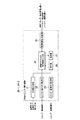
本実施形態による地域エネルギー管理システム1は、建物A内で使用および創出、蓄積されるエネルギーを管理する建物内エネルギー管理システム3と、建物B内で使用および創出、蓄積されるエネルギーを管理する建物内エネルギー管理システム4とが、ネットワーク5を介して供給電力を管理する電力会社等のエネルギー供給システム2に接続されて構成されている。建物Cについては、建物内エネルギー管理システムが構築されておらず、建物内エネルギー管理情報の取得が不可能な状態であるものとする。
The regional energy management system 1 according to this embodiment includes an in-building
建物内エネルギー管理システム3は、建物A内に設置されたエネルギー創出装置11−1と、エネルギー蓄積装置12−1と、UPS(無停電電源装置)13−1と、負荷装置としての照明機器14−1および空調機15−1と、計測器としての電力計16−1と、温度計17−1と、湿度計18−1と、これらの装置に接続されるとともにネットワーク5に接続された建物内エネルギー管理装置20−1と、ネットワーク5に接続された地域エネルギー統合管理装置30とを有する。
The building
地域エネルギー統合管理装置30に関しては、ネットワーク5に接続されており、エネルギー供給システム2、各建物の建物内エネルギー管理システム3と情報のやり取りが出来る構成であればよい。
The regional energy integrated
この建物Aと建物Bとは近接しており、建物Aのエネルギー創出装置11−1、エネルギー蓄積装置12−1、UPS13−1、照明機器14−1、および空調機15−1と、建物Bのエネルギー創出装置11−2、エネルギー蓄積装置12−2、UPS13−2、照明機器14−2、および空調機15−2とは、相互に接続されてエネルギーを供給可能な状態に構築されているものとする。尚、全てが相互接続されている必要はなく、部分的に相互接続されていても良い。 The building A and the building B are close to each other. The building A energy creation device 11-1, the energy storage device 12-1, the UPS 13-1, the lighting device 14-1, the air conditioner 15-1, and the building B The energy creation device 11-2, the energy storage device 12-2, the UPS 13-2, the lighting device 14-2, and the air conditioner 15-2 are connected to each other and constructed to be capable of supplying energy. Shall. Note that not all of them need to be interconnected, and may be partially interconnected.
エネルギー創出装置11−1は、太陽光発電装置、風力発電装置等であり、太陽光エネルギーや風力エネルギー等の再生可能エネルギーを電力に変換することで電気エネルギーを創出する。 The energy creation device 11-1 is a solar power generation device, a wind power generation device, or the like, and creates electrical energy by converting renewable energy such as solar energy or wind energy into electric power.
エネルギー蓄積装置12−1は、蓄電池、蓄熱層、貯水槽、またはフライホイール等であり、エネルギー創出装置11−1で創出された電気エネルギーを利用形態に合わせた状態で蓄積する。例えば、蓄電池であれば、供給された電気エネルギーを、一般的な定置型蓄電池に蓄積する。また蓄熱層であれば、供給された電気エネルギーを利用して発熱コイル等により熱交換して温水を生成して熱エネルギーとして蓄積する。また貯水槽であれば、供給された電力を利用して貯水する水をポンプで高所にくみ上げ、位置エネルギーとして蓄積する。またフライホイールであれば、供給された電力を利用してフライホイールを回転させ、運動エネルギーとして蓄積する。 The energy storage device 12-1 is a storage battery, a heat storage layer, a water storage tank, a flywheel, or the like, and stores the electrical energy created by the energy creation device 11-1 in a state that matches the usage form. For example, in the case of a storage battery, the supplied electrical energy is stored in a general stationary storage battery. In the case of a heat storage layer, the supplied electrical energy is used to exchange heat with a heating coil or the like to generate hot water and store it as thermal energy. In the case of a water storage tank, the water stored using the supplied power is pumped up to a high place and stored as potential energy. In the case of a flywheel, the supplied electric power is used to rotate the flywheel and accumulate it as kinetic energy.
UPS13−1は、エネルギー供給システム2から供給された電気エネルギー、エネルギー創出装置11−1から供給された電気エネルギー、エネルギー蓄積装置12−1に蓄積された電気エネルギーや、熱エネルギー、または位置エネルギーや運動エネルギーから変換された電気エネルギー等を、負荷装置である照明機器14−1および空調機15−1に供給する。
The UPS 13-1 is an electric energy supplied from the
照明機器14−1は、UPS13−1から供給される電気エネルギーを利用して稼働する。また、現在、研究開発が進められている直流電源対応のLED照明などの直流電源対応機器が設置される場合は、エネルギー蓄電装置12−1より直接、電気エネルギーを供給される場合もある。 The lighting device 14-1 operates using electric energy supplied from the UPS 13-1. In addition, when a DC power source compatible device such as LED lighting corresponding to a DC power source currently under research and development is installed, electric energy may be directly supplied from the energy storage device 12-1.
空調機15−1は、UPS13−1から供給される電気エネルギーや、エネルギー蓄積装置12−1から供給される温水を利用して稼働する。 The air conditioner 15-1 operates using electric energy supplied from the UPS 13-1 or hot water supplied from the energy storage device 12-1.
電力計16−1は、UPS13−1から照明機器14−1や空調機15−1等の負荷装置に供給される電力を計測することで、当該建物の中で使用される電力量を計測する。 The power meter 16-1 measures the amount of power used in the building by measuring the power supplied from the UPS 13-1 to the load device such as the lighting device 14-1 or the air conditioner 15-1. .
温度計17−1は、当該建物内のエネルギー管理に利用する建物内外の温度を計測する。 The thermometer 17-1 measures the temperature inside and outside the building used for energy management in the building.
湿度計18−1は、当該建物内のエネルギー管理に利用する建物内外の湿度を計測する。 The hygrometer 18-1 measures the humidity inside and outside the building used for energy management in the building.
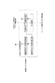
建物内エネルギー管理装置20−1は、建物Aで使用および創出、蓄積されるエネルギーを管理する装置であり、図2に示すように、計測値取得部21と、エネルギー創出状況取得部22と、エネルギー蓄積状況取得部23と、建物内エネルギー管理情報生成部24と、管理情報送受信部25と、操作部26と、表示部27とを有する。
The building energy management device 20-1 is a device that manages the energy used, created, and stored in the building A. As shown in FIG. 2, the measured
計測値取得部21は、電力計16で計測された電力量計測値、温度計17で計測された温度計測値、および湿度計18で計測された湿度計測値を取得する。
The measurement
エネルギー創出状況取得部22は、エネルギー創出装置11−1におけるエネルギーの創出量等を示すエネルギー創出状況情報を取得する。
The energy creation
エネルギー蓄積状況取得部23は、エネルギー蓄積装置12におけるエネルギーの蓄積量等を示すエネルギー蓄積状況情報を取得する。 The energy storage status acquisition unit 23 acquires energy storage status information indicating the amount of energy stored in the energy storage device 12.
建物内エネルギー管理情報生成部24は、エネルギー創出状況取得部22で取得されたエネルギーの創出状況情報と、エネルギー蓄積状況取得部23で取得されたエネルギーの蓄積状況情報と、計測値取得部21で取得された電力量計測値、温度計測値、および湿度計測値とから、当該建物内のエネルギーの不足情報および余剰情報や、エネルギー創出装置11−1、エネルギー蓄積装置12−1、UPS13−1、照明機器14−1、空調機15−1の運転制御情報を含む建物内エネルギー管理情報を生成する。また建物内エネルギー管理情報生成部24は、地域エネルギー統合管理装置30から送信される地域エネルギー管理情報やデマンド削減量情報(エネルギー使用料の削減要求情報等)に基づいて、エネルギー創出装置11−1、エネルギー蓄積装置12−1、UPS13−1、照明機器14−1、空調機15−1の運転制御情報を含む建物内エネルギー管理情報を生成する。
The energy management
管理情報送受信部25は、建物内エネルギー管理情報生成部24で生成された建物内エネルギー管理情報を地域エネルギー統合管理装置30に送信するとともに、必要に応じてエネルギー創出装置11−1、エネルギー蓄積装置12−1、UPS13−1、照明機器14−1、空調機15−1に送信する。また管理情報送受信部25は、地域エネルギー統合管理装置30から送信される地域エネルギー管理情報やデマンド削減量情報を、建物内エネルギー管理情報生成部24に送出する。
The management information transmission /
操作部26は、建物内エネルギー管理システム3の管理人により操作され、建物内エネルギー管理情報生成部24で生成された建物内エネルギー管理情報を表示させるための操作等を行う。
The
表示部27は、操作部26において実行された操作に基づいて、建物内エネルギー管理情報生成部24で生成された建物内エネルギー管理情報を表示する。
The display unit 27 displays the building energy management information generated by the building energy management
また、建物内エネルギー管理システム4は、建物B内に設置されたエネルギー創出装置11−2と、エネルギー蓄積装置12−2と、UPS(無停電電源装置)13−2と、負荷装置としての照明機器14−2および空調機15−2と、電力計16−2と、温度計17−2と、湿度計18−2と、これらの装置に接続されるとともにネットワーク5に接続された建物内エネルギー管理装置20−2とを有する。
The building energy management system 4 includes an energy creation device 11-2 installed in the building B, an energy storage device 12-2, a UPS (uninterruptible power supply) 13-2, and a lighting device as a load device. Equipment 14-2, air conditioner 15-2, wattmeter 16-2, thermometer 17-2, hygrometer 18-2, building energy connected to these devices and connected to
この建物B内の各装置の機能は、建物A内の対応する各装置の機能と同様であるため、詳細な説明は省略する。 Since the function of each device in the building B is the same as the function of each corresponding device in the building A, detailed description is omitted.
地域エネルギー統合管理装置30は、管理対象地域内の建物A、建物B、および建物Cで使用および創出されるエネルギーを統合管理する装置であり、建物内エネルギー管理情報取得部31と、地域エネルギー管理情報生成部32と、指令送信部33と、建物内エネルギー管理情報推定部34とを有する。
The regional energy integrated
建物内エネルギー管理情報取得部31は、各建物(建物Aおよび建物B)の管理情報送受信部25から送信された建物内エネルギー管理情報を取得する。
The building energy management
地域エネルギー管理情報生成部32は、建物内エネルギー管理情報取得部31で取得された複数の建物の建物内エネルギー管理情報に基づいて、管理対象地域内の異なる建物間でエネルギー供給を調整するための地域エネルギー管理情報を生成する。また、エネルギー供給システム2からネットワーク5を介して当該地域の消費エネルギーを削減するためのデマンド削減指令が送信されたときに、このデマンド削減指令により削減するデマンド量を建物ごとに配分した建物毎デマンド削減量情報を、取得された複数の建物の建物内エネルギー管理情報に基づいて生成する。
The regional energy management
指令送信部33は、地域エネルギー管理情報生成部32で生成された地域エネルギー管理情報、建物毎デマンド削減量情報を、該当する建物の建物内エネルギー管理装置20に送信する。
The command transmission unit 33 transmits the regional energy management information and the per-building demand reduction amount information generated by the regional energy management
建物内エネルギー管理情報推定部34は、対象地域内の建物のうち、建物内エネルギー管理情報の取得が不可能な建物に関する、建物内エネルギー管理情報の推定情報である推定管理情報を生成する。 The in-building energy management information estimation unit 34 generates estimated management information that is estimation information of in-building energy management information related to a building in which acquisition of in-building energy management information is impossible among buildings in the target area.
〈一実施形態による地域エネルギー管理システムの動作〉
本実施形態による地域エネルギー管理システム1の動作として、(1)複数建物間のエネルギー分配調整処理、および(2)デマンド削減指令対応処理が実行される場合について説明する。
<Operation of Regional Energy Management System According to One Embodiment>
As an operation of the regional energy management system 1 according to the present embodiment, a case where (1) energy distribution adjustment processing between a plurality of buildings and (2) demand reduction command response processing is executed will be described.
(1)複数建物間のエネルギー分配調整処理
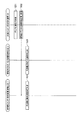
本実施形態による地域エネルギー管理システム1において、建物Aと建物Bとの間で相互にエネルギーの分配調整が行われるときの動作について、図4のシーケンス図を参照して説明する。
(1) Energy distribution adjustment processing between a plurality of buildings In the regional energy management system 1 according to the present embodiment, an operation when energy distribution adjustment is performed between the building A and the building B is shown in the sequence diagram of FIG. Will be described with reference to FIG.
まず、管理対象の地域の建物のうち、建物内のエネルギー管理が行われている建物Aにおいて、温度計17−1で当該建物A内の建物内外の温度計測値が計測され、また湿度計18−1で当該建物A内の建物内外の湿度計測値が計測され、これらの温度計測値および湿度計測値が建物内エネルギー管理装置20−1の計測値取得部21で取得される(S1)。
First, among the buildings in the area to be managed, in the building A where energy management is performed in the building, the thermometer 17-1 measures the temperature measurement values inside and outside the building A, and the hygrometer 18. −1, the humidity measurement values inside and outside the building A are measured, and these temperature measurement values and humidity measurement values are acquired by the measurement
計測値取得部21で取得された温度計測値および湿度計測値は建物内エネルギー管理情報生成部24で取得され、この温度計測値および湿度計測値に基づいて照明機器14−1および空調機15−1の運転制御情報が生成される。生成された運転制御情報は、管理情報送受信部25から照明機器14−1および空調機15−1に送信されてこれらの運転が制御される(S2)。
The temperature measurement value and the humidity measurement value acquired by the measurement
また、建物A内の太陽光発電装置、風力発電装置等で構成されたエネルギー創出装置11−1において、太陽光エネルギーや風力エネルギー等の再生可能エネルギーが電気エネルギーに変換されることで電気エネルギーが創出される。 Moreover, in the energy creation apparatus 11-1 comprised with the solar power generation device in the building A, a wind power generation device, etc., electric energy is obtained by converting renewable energy, such as solar energy and wind energy, into electrical energy. Created.
エネルギー創出装置11−1で創出された電気エネルギーの電力量等は、建物内エネルギー管理装置20−1のエネルギー創出状況取得部22においてエネルギーの創出状況情報として取得される(S3)。
The amount of electric energy generated by the energy creation device 11-1 is acquired as energy creation status information in the energy creation
エネルギー創出状況取得部22で取得されたエネルギーの創出状況情報は、建物内エネルギー管理情報生成部24で取得され、このエネルギーの創出状況情報と、ステップS3で生成された照明機器14−1および空調機15−1の運転制御情報とに基づいて、エネルギー蓄積装置12−1へのエネルギー蓄積指示、UPS13−1へのエネルギー供給指示が生成される。生成されたエネルギー蓄積指示、エネルギー供給指示は、管理情報送受信部25からエネルギー創出装置11−1、エネルギー蓄積装置12−1、UPS13−1に送信されてエネルギー管理が行われる(S4)。
The energy creation status information acquired by the energy creation
例えば、生成された運転制御情報に基づく照明機器14−1および空調機15−1の運転が、エネルギー創出装置11−1で創出されている電気エネルギーで稼働可能なときには、エネルギー創出装置11−1で創出される電気エネルギーを、UPS13−1を介して照明機器14−1および空調機15−1に供給するように建物内エネルギー管理情報生成部24でエネルギー供給指示が生成され、このエネルギー供給指示がエネルギー創出装置11−1およびUPS13−1に送信される。尚、エネルギー創出装置11−1と照明機器14−1等の負荷設備とが、直流電源供給可能であるなどの場合は、UPS13−1を介さず、エネルギー創出装置11−1で創出される電気エネルギーを直接照明機器14−1に供給するようにエネルギー供給指示が生成される。
For example, when the operation of the lighting device 14-1 and the air conditioner 15-1 based on the generated operation control information can be operated with the electrical energy created by the energy creation device 11-1, the energy creation device 11-1 An energy supply instruction is generated in the building energy management
また、エネルギー創出装置11−1において、照明機器14−1および空調機15−1に提供されるよりも過剰の電気エネルギーが創出されたときには、エネルギー創出装置11−1で創出される電気エネルギーをエネルギー蓄積装置12−1に蓄積させるように建物内エネルギー管理情報生成部24でエネルギー蓄積指示が生成され、このエネルギー蓄積指示がエネルギー創出装置11−1およびエネルギー蓄積装置12−1に送信される。
Moreover, in the energy creation apparatus 11-1, when excess electrical energy is created rather than provided to the lighting equipment 14-1 and the air conditioner 15-1, the electrical energy created by the energy creation apparatus 11-1 is changed. An energy storage instruction is generated in the building energy management
ここで、UPS13−1から照明機器14−1および空調機15−1に提供された電気量は電力計16−1で計測され、当該建物Aの使用電力量計測値として建物内エネルギー管理装置20−1の計測値取得部21で取得される(S5)。計測値取得部21で取得された使用電力量計測値は、建物内エネルギー管理情報生成部24で取得される。
Here, the amount of electricity provided from the UPS 13-1 to the lighting device 14-1 and the air conditioner 15-1 is measured by the wattmeter 16-1, and the building energy management apparatus 20 is used as a measured power consumption value of the building A. -1 of the measured value acquisition unit 21 (S5). The power consumption measurement value acquired by the measurement
また、エネルギー蓄積装置12−1に蓄積されたエネルギー量は、エネルギー蓄積状況情報として建物内エネルギー管理装置20−1のエネルギー蓄積状況取得部23で取得される(S6)。エネルギー蓄積状況取得部23で取得されたエネルギー蓄積状況情報は、建物内エネルギー管理情報生成部24で取得される。
The amount of energy stored in the energy storage device 12-1 is acquired by the energy storage status acquisition unit 23 of the building energy management device 20-1 as energy storage status information (S6). The energy storage status information acquired by the energy storage status acquisition unit 23 is acquired by the building energy management
そして建物内エネルギー管理情報生成部24において、取得されたエネルギーの創出状況情報と、使用電力量計測値と、エネルギー蓄積状況情報とから、当該建物内のエネルギーの不足情報および余剰情報が生成される。生成された当該建物内のエネルギーの不足情報および余剰情報は、ネットワーク5を介して地域エネルギー統合管理装置30に送信される(S7)。
Then, in the building energy management
同様にして、建物B内においても、建物内エネルギー管理装置20−2の建物内エネルギー管理情報生成部24において、照明機器14−2および空調機15−2の運転制御情報、エネルギー蓄積装置12−1へのエネルギー蓄積指示、UPS13−1へのエネルギー供給指示、当該建物内のエネルギーの不足情報および余剰情報が生成される(ステップS8〜S13)。生成された当該建物内のエネルギーの不足情報および余剰情報は、ネットワーク5を介して地域エネルギー統合管理装置30に送信される(S14)。
Similarly, in the building B, in the building energy management
地域エネルギー統合管理装置30では、建物内エネルギー管理装置20−1および20−2から送信された各建物内のエネルギーの不足情報および余剰情報が建物内エネルギー管理情報取得部31で取得され(S15)、地域エネルギー管理情報生成部32において、これらの情報に基づいて建物Aと建物Bとの間で省エネ効果を向上させるとともにCO2排出量を抑えるようにエネルギー供給を調整するための地域エネルギー管理情報が生成される(S16)。
In the regional energy integrated
例えば、熱エネルギーが不足している不足情報が建物Aの建物内エネルギー管理装置20−1から取得され、余剰の熱エネルギーとしての温水が蓄積されている余剰情報が建物Bの建物内エネルギー管理装置20−2から取得された場合に、建物Bから建物Aに配管を通じてポンプにより温水を提供(売却)するように配分するための地域エネルギー管理情報が生成される。 For example, the shortage information that the thermal energy is insufficient is acquired from the in-building energy management apparatus 20-1 of the building A, and the surplus information in which hot water as surplus thermal energy is accumulated is the in-building energy management apparatus of the building B. When acquired from 20-2, regional energy management information for allocating the hot water to be provided (sold) from the building B to the building A through a pipe through a pipe is generated.
生成された地域エネルギー管理情報は、該当する建物Aの建物内エネルギー管理装置20−1および建物Bの建物内エネルギー管理装置20−2に送信される(S17)。 The generated regional energy management information is transmitted to the in-building energy management apparatus 20-1 of the corresponding building A and the in-building energy management apparatus 20-2 of the building B (S17).
そして、各建物内エネルギー管理装置20において、取得された地域エネルギー管理情報に対応するための、建物内の各装置の動作制御指示が生成され、該当する装置に送信される(S17、S18)。 Then, in each building energy management device 20, an operation control instruction for each device in the building to correspond to the acquired regional energy management information is generated and transmitted to the corresponding device (S17, S18).
例えば、上述したような建物Bから建物Aに温水を提供するための地域エネルギー管理情報が地域エネルギー統合管理装置30から送信された場合には、この地域エネルギー管理情報が建物B内の建物内エネルギー管理装置20−2において管理情報送受信部25を介して建物内エネルギー管理情報生成部24で取得され、建物Bのエネルギー蓄積装置12−2により熱エネルギーとして蓄積されている温水を建物Aに供給するための熱エネルギー提供指示が生成される。
For example, when the regional energy management information for providing warm water from the building B to the building A as described above is transmitted from the regional energy integrated
生成された熱エネルギー提供指示は、エネルギー蓄積装置12−2に送信され、エネルギー蓄積装置12−2により蓄積された温水が建物Aに提供されるように制御される。 The generated heat energy provision instruction is transmitted to the energy storage device 12-2, and the hot water accumulated by the energy storage device 12-2 is controlled to be provided to the building A.
また、建物内エネルギー管理情報生成部24で生成された各種情報は、建物内エネルギー管理システム3の管理人により操作部26が操作されることにより、表示部27に表示され、監視に利用される。更に、必要に応じて、制御指令発報時に表示部27の表示を確認し、操作部26にてその制御指令を実施するかどうかの確認を行う様に構成することにより、制御指令の実施するか否かを管理者にて判断するタイミングを持つような構成にすることも可能である。
Various information generated by the building energy management
(2)デマンド削減指令対応処理
上述したように建物Aと建物Bとの間でエネルギー分配調整処理が行われている状態で、この地域エネルギー管理システム1において、エネルギー供給システム2からデマンド削減指令が送信されたときの動作について、図5のシーケンス図を参照して説明する。
(2) Demand reduction command response processing In the state where the energy distribution adjustment processing is performed between the building A and the building B as described above, in this local energy management system 1, a demand reduction command is issued from the
まず、エネルギー供給システム2から当該管理対象地域に対してデマンド削減指令が送信されると、地域エネルギー統合管理装置30においてこのデマンド削減指令が取得される(S21)。
First, when a demand reduction command is transmitted from the
地域エネルギー統合管理装置30では、デマンド削減指令が地域エネルギー管理情報生成部32で取得され、このデマンド削減指令により削減するデマンド量を建物ごとに配分した建物毎デマンド削減量情報が、取得された複数の建物の建物内エネルギー管理情報に基づいて生成される。
In the regional energy integrated
このとき、対象地域内の建物のうち、建物内エネルギー管理情報の取得が不可能な建物、例えば建物Cに関する建物内エネルギー管理情報は、建物内エネルギー管理情報推定部34において当該建物内エネルギー管理情報の推定情報である推定管理情報が生成され、これが利用されて建物内デマンド削減量情報が生成される。この推定管理情報は、当該建物の述べ床面積、設置設備に基づいて生成することが考えられ、また可能であれば建物内設備のシミュレーションを行う技術を利用して生成してもよい。 At this time, among the buildings in the target area, the building energy management information related to the building incapable of acquiring the building energy management information, for example, the building C, is stored in the building energy management information estimation unit 34. Estimated management information, which is the estimated information, is generated and used to generate in-building demand reduction information. The estimated management information may be generated based on the stated floor area of the building and the installation equipment, and may be generated using a technique for simulating the equipment in the building if possible.
また、当該システムの稼動中に故障等により建物内エネルギー管理情報が取得不可能となった建物に関しては、取得不可能となる前までに時系列で取得された建物内エネルギー管理情報を用いて自己回帰モデル等で推定する方法や、過去の情報のうち類似した環境の日時の情報に基づいて推定する方法等が用いられ、推定管理情報が生成される。 For buildings where building energy management information cannot be acquired due to a failure, etc. during the operation of the system, self-management is performed using the building energy management information acquired in chronological order before it can be acquired. A method of estimation using a regression model or the like, a method of estimation based on date information of a similar environment among past information, and the like are used, and estimation management information is generated.
そして、推定管理情報により建物内エネルギー管理情報が取得された建物に関してはデマンド削減が不可能とし、建物内エネルギー管理システムによりエネルギー管理が実行されている建物内で、要求されたデマンド削減を行うように建物内デマンド削減量情報が生成される。 In addition, it is considered that demand reduction is impossible for a building for which energy management information in the building has been obtained from the estimated management information, and that demand reduction is performed in the building where energy management is being executed by the building energy management system. In-building demand reduction information is generated.
生成された建物毎デマンド削減量情報は、それぞれ該当する建物の建物内エネルギー管理装置20−1、20−2に送信される(S22)。 The generated per-building demand reduction amount information is transmitted to the in-building energy management apparatuses 20-1 and 20-2 of the corresponding building, respectively (S22).
各建物内エネルギー管理装置20−1、20−2では、送信された建物毎デマンド削減量情報が管理情報送受信部25を介して建物内エネルギー管理情報生成部24で取得され、この建物毎デマンド削減量情報に基づいて建物内の各装置の動作制御指示が生成され、該当する装置に送信される(S23、S24)。
In each in-building energy management apparatus 20-1 and 20-2, the transmitted per-building demand reduction amount information is acquired by the in-building energy management
以上の本実施形態によれば、個々の建物内のみならず、管理対象地域の複数の建物間において、効率良くエネルギー管理を行うことが可能になり、地域全体として省エネ効果を向上させ、またCO2排出量を抑えるように制御することができる。
According to the above embodiment, it becomes possible to efficiently perform energy management not only within individual buildings but also between a plurality of buildings in the management target area, improving the energy saving effect as a whole area, and reducing
またこのとき、管理情報の入手が不可能な建物に関しても、推定情報を生成する手段を用いることにより、管理対象として含めることができる。 Further, at this time, a building for which management information cannot be obtained can be included as a management target by using a means for generating estimated information.
本発明の実施形態を説明したが、この実施形態は、例として提示したものであり、発明の範囲を限定することは意図していない。この新規な実施形態は、その他の様々な形態で実施されることが可能であり、発明の要旨を逸脱しない範囲で、種々の省略、置き換え、変更を行うことができる。この実施形態やその変形は、発明の範囲や要旨に含まれるとともに、特許請求の範囲に記載された発明とその均等の範囲に含まれる。 Although the embodiment of the present invention has been described, this embodiment is presented as an example and is not intended to limit the scope of the invention. The novel embodiment can be implemented in various other forms, and various omissions, replacements, and changes can be made without departing from the scope of the invention. This embodiment and its modifications are included in the scope and gist of the invention, and are included in the invention described in the claims and the equivalents thereof.
例えば、本実施形態においては地域エネルギー統合管理装置が建物Aの建物内エネルギー管理システム内に設置された場合について説明したが、これには限定されず、地域エネルギー統合管理装置が各建物内エネルギー管理システムとは別に独立して設置されるようにしてもよい。 For example, in the present embodiment, the case where the regional energy integrated management apparatus is installed in the in-building energy management system of the building A has been described. It may be installed separately from the system.
また、本発明で記載しているデマンド削減指令に対する各装置の動作指令に対し、全体的な省エネ効率は所望のものが得られない可能性はあるが、状況やシステム所有者の要望により、各ビルの管理者が、あらかじめ動作指令を確認し、動作指令を実際に実施するか、キャンセルするかを選択できるように表示部、操作部を構築することも可能である。 In addition, there is a possibility that the overall energy saving efficiency may not be obtained with respect to the operation command of each device with respect to the demand reduction command described in the present invention, but depending on the situation and the request of the system owner, It is also possible to construct a display unit and an operation unit so that the building administrator can confirm the operation command in advance and select whether to actually execute or cancel the operation command.
1…地域エネルギー管理システム
2…エネルギー供給システム
3、4…建物内エネルギー管理システム
5…ネットワーク
11−1、11−2…エネルギー創出装置
12−1、12−2…エネルギー蓄積装置
13−1、13−2…UPS
14−1、14−2…照明機器
15−1、15−2…空調機
16−1、16−2…電力計
17−1、17−2…温度計
18−1、18−2…湿度計
20−1、20−2…建物内エネルギー管理装置
21…計測値取得部
22…エネルギー創出状況取得部
23…エネルギー蓄積状況取得部
24…建物内エネルギー管理情報生成部
25…管理情報送受信部
26…操作部
27…表示部
30…地域エネルギー統合管理装置
31…建物内エネルギー管理情報取得部
32…地域エネルギー管理情報生成部
33…指令送信部
34…建物内エネルギー管理情報推定部
DESCRIPTION OF SYMBOLS 1 ... Local
14-1, 14-2 ... Lighting equipment 15-1, 15-2 ... Air conditioner 16-1, 16-2 ... Wattmeter 17-1, 17-2 ... Thermometer 18-1, 18-2 ... Hygrometer 20-1, 20-2 ... Building
Claims (6)
前記建物内エネルギー管理装置はそれぞれ、
該建物内のエネルギー不足情報および余剰情報を含む建物内エネルギー管理情報を生成する建物内エネルギー管理情報生成部と、
前記建物内エネルギー管理情報生成部で生成された建物内エネルギー管理情報を前記地域エネルギー統合管理装置に送信する管理情報送受信部と
を備え、
前記地域エネルギー管理システムは、
前記複数の建物に設置された建物内エネルギー管理装置からそれぞれ、前記建物内エネルギー管理情報を取得する建物内エネルギー管理情報取得部と、
前記建物内エネルギー管理情報取得部で取得された複数の建物の建物内エネルギー管理情報に基づいて、異なる建物間で相互にエネルギー供給を調整するための地域エネルギー管理情報を生成する地域エネルギー管理情報生成部と、
前記地域エネルギー管理情報生成部で生成された地域エネルギー管理情報を、対応する建物に送信する指令送信部と
を備えることを特徴とする地域エネルギー管理システム。 In a regional energy management system configured by connecting a building energy management system installed in each of a plurality of buildings and a regional energy integrated management device connected to the plurality of building energy management systems,
Each of the energy management devices in the building is
An in-building energy management information generating unit for generating in-building energy management information including energy shortage information and surplus information in the building;
A management information transmitting / receiving unit that transmits the building energy management information generated by the building energy management information generating unit to the regional energy integrated management device;
The regional energy management system is:
In-building energy management information acquisition unit for acquiring the in-building energy management information, respectively, from the building energy management devices installed in the plurality of buildings,
Regional energy management information generation for generating local energy management information for mutually adjusting energy supply between different buildings based on in-building energy management information of a plurality of buildings acquired by the in-building energy management information acquisition unit And
A regional energy management system comprising: a command transmission unit that transmits the regional energy management information generated by the regional energy management information generation unit to a corresponding building.
前記建物内エネルギー管理情報生成部は、前記エネルギー創出装置で創出されたエネルギーの状況を示すエネルギー創出状況情報と、前記エネルギー蓄積装置に蓄積されたエネルギーの状況を示すエネルギー蓄積状況情報と、前記電力計側計で計測された電力量計測値とから、前記建物内エネルギー管理情報を生成する
ことを特徴とする請求項1に記載の地域エネルギー管理システム。 The building energy management device includes an energy creation device that is installed in the building and generates electrical energy by converting renewable energy into electric power, an energy storage device that stores energy, and a load in the building. Connected to a power meter that measures the amount of power used by the device,
The energy management information generating unit in the building includes energy creation status information indicating a status of energy generated by the energy generating device, energy storage status information indicating a status of energy stored in the energy storage device, and the power The regional energy management system according to claim 1, wherein the building energy management information is generated from a measured electric energy value measured by a meter.
前記複数の建物からそれぞれ、該建物内のエネルギー不足情報および余剰情報を含む建物内エネルギー管理情報を取得する建物内エネルギー管理情報取得部と、
前記建物内エネルギー管理情報取得部で取得された複数の建物の建物内エネルギー管理情報に基づいて、管理対象の地域内の異なる建物間で相互にエネルギー供給を調整するための地域エネルギー管理情報を生成する地域エネルギー管理情報生成部と、
前記地域エネルギー管理情報生成部で生成された地域エネルギー管理情報を、対応する建物に送信する指令送信部と
を備えることを特徴とする地域エネルギー統合管理装置。 In a regional energy integrated management device that manages energy used and created in multiple buildings,
In-building energy management information acquisition unit for acquiring in-building energy management information including energy shortage information and surplus information in each of the plurality of buildings,
Based on the building energy management information acquired by the building energy management information acquisition unit, generates regional energy management information for mutually adjusting energy supply between different buildings in the management target area. A local energy management information generation unit,
A regional energy integrated management apparatus comprising: a command transmission unit configured to transmit the regional energy management information generated by the regional energy management information generation unit to a corresponding building.
前記地域エネルギー管理情報生成部は、前記エネルギー供給システムからデマンド削減指令が送信されたときにこれを取得し、このデマンド削減指令により削減するデマンド量を建物ごとに配分した建物毎デマンド削減量情報を、取得された複数の建物の建物内エネルギー管理情報に基づいて生成する
ことを特徴とする請求項3に記載の地域エネルギー統合管理装置。 The regional energy integrated management device is connected to an energy supply system that manages power supplied in the region,
The regional energy management information generation unit obtains a demand reduction command when the demand reduction command is transmitted from the energy supply system, and obtains demand reduction amount information for each building in which the demand amount to be reduced by the demand reduction command is allocated to each building. The regional energy integrated management device according to claim 3, wherein the regional energy integrated management device is generated based on the acquired in-building energy management information of a plurality of buildings.
前記複数の建物からそれぞれ、該建物内のエネルギー不足情報および余剰情報を含む建物内エネルギー管理情報を取得する建物内エネルギー管理情報取得ステップと、
前記建物内エネルギー管理情報取得ステップで取得された複数の建物の建物内エネルギー管理情報に基づいて、管理対象の地域内の異なる建物間で相互にエネルギー供給を調整するための地域エネルギー管理情報を生成する地域エネルギー管理情報生成ステップと、
前記地域エネルギー管理情報生成ステップで生成された地域エネルギー管理情報を、対応する建物に送信する指令送信ステップと
を有することを特徴とする地域エネルギー統合管理方法。 A regional energy integrated management device that manages energy used and created in multiple buildings.
In-building energy management information acquisition step for acquiring in-building energy management information including energy shortage information and surplus information in each of the plurality of buildings,
Based on the in-building energy management information of the plurality of buildings acquired in the in-building energy management information acquisition step, regional energy management information for adjusting energy supply between different buildings in the management target area is generated. Generating local energy management information,
A regional energy integrated management method comprising: a command transmission step of transmitting the regional energy management information generated in the regional energy management information generation step to a corresponding building.
前記地域エネルギー管理情報生成ステップでは、前記エネルギー供給システムからデマンド削減指令が送信されたときにこれを取得し、このデマンド削減指令により削減するデマンド量を建物ごとに配分した建物毎デマンド削減量情報を、取得された複数の建物の建物内エネルギー管理情報に基づいて生成する
ことを特徴とする請求項5に記載の地域エネルギー統合管理方法。 The regional energy integrated management device is connected to an energy supply system that manages power supplied in the region,
In the regional energy management information generating step, when a demand reduction command is transmitted from the energy supply system, it is acquired, and the demand reduction amount information for each building obtained by distributing the demand amount reduced by the demand reduction command for each building is obtained. The regional energy integrated management method according to claim 5, wherein the regional energy integrated management method is generated based on the acquired in-building energy management information of a plurality of buildings.
Priority Applications (7)
| Application Number | Priority Date | Filing Date | Title |
|---|---|---|---|
| JP2011037003A JP2012175855A (en) | 2011-02-23 | 2011-02-23 | Area energy management system, and area energy integrated management apparatus and area energy integrated management method used therefor |
| SG2012016325A SG183787A1 (en) | 2011-02-23 | 2012-02-02 | Regional energy management system, regional energy integrated management device and regional energy integrated management method used in regional energy management system |
| CN201510094429.6A CN104617675A (en) | 2011-02-23 | 2012-02-02 | Regional energy management system, and integrated regional energy management apparatus and integrated regional energy management method to be used therefor |
| PCT/JP2012/052405 WO2012114844A1 (en) | 2011-02-23 | 2012-02-02 | Regional energy management system, and integrated regional energy management apparatus and integrated regional energy management method to be used therefor |
| EP12705777.6A EP2680391A4 (en) | 2011-02-23 | 2012-02-02 | Regional energy management system, and integrated regional energy management apparatus and integrated regional energy management method to be used therefor |
| CN2012800000566A CN102771027A (en) | 2011-02-23 | 2012-02-02 | Regional energy management system, and integrated regional energy management apparatus and integrated regional energy management method to be used therefor |
| US13/413,097 US8938320B2 (en) | 2011-02-23 | 2012-03-06 | Regional energy management system, regional energy integrated management device and regional energy integrated management method used in regional energy management system |
Applications Claiming Priority (1)
| Application Number | Priority Date | Filing Date | Title |
|---|---|---|---|
| JP2011037003A JP2012175855A (en) | 2011-02-23 | 2011-02-23 | Area energy management system, and area energy integrated management apparatus and area energy integrated management method used therefor |
Related Child Applications (1)
| Application Number | Title | Priority Date | Filing Date |
|---|---|---|---|
| JP2015007858A Division JP2015109801A (en) | 2015-01-19 | 2015-01-19 | Regional energy management system and regional energy integrated management apparatus, energy management apparatus, regional energy management method, regional energy integrated management method, energy management method, regional energy integrated management program and energy management program used for the same |
Publications (1)
| Publication Number | Publication Date |
|---|---|
| JP2012175855A true JP2012175855A (en) | 2012-09-10 |
Family
ID=46720632
Family Applications (1)
| Application Number | Title | Priority Date | Filing Date |
|---|---|---|---|
| JP2011037003A Pending JP2012175855A (en) | 2011-02-23 | 2011-02-23 | Area energy management system, and area energy integrated management apparatus and area energy integrated management method used therefor |
Country Status (5)
| Country | Link |
|---|---|
| EP (1) | EP2680391A4 (en) |
| JP (1) | JP2012175855A (en) |
| CN (2) | CN102771027A (en) |
| SG (1) | SG183787A1 (en) |
| WO (1) | WO2012114844A1 (en) |
Cited By (4)
| Publication number | Priority date | Publication date | Assignee | Title |
|---|---|---|---|---|
| JP2014056429A (en) * | 2012-09-12 | 2014-03-27 | Sekisui Chem Co Ltd | Energy management system, energy management device and method and program for energy management |
| JP2015138424A (en) * | 2014-01-23 | 2015-07-30 | 株式会社日立製作所 | Electric heat accommodation system |
| WO2015119119A1 (en) * | 2014-02-07 | 2015-08-13 | 株式会社 東芝 | Air conditioning system, air conditioning device, air conditioning control method and program |
| CN115907350A (en) * | 2022-11-04 | 2023-04-04 | 华北电力大学 | Energy management method and system of building comprehensive energy system |
Families Citing this family (1)
| Publication number | Priority date | Publication date | Assignee | Title |
|---|---|---|---|---|
| CN117455204B (en) * | 2023-12-25 | 2024-04-09 | 浙江浙能能源服务有限公司 | Regional energy optimization method and system based on building load |
Citations (13)
| Publication number | Priority date | Publication date | Assignee | Title |
|---|---|---|---|---|
| JPH09135536A (en) * | 1995-11-07 | 1997-05-20 | Hitachi Ltd | Power system interconnection system |
| JP2002044870A (en) * | 2000-07-27 | 2002-02-08 | Nippon Telegr & Teleph Corp <Ntt> | Dispersed energy community system and control method |
| JP2003289627A (en) * | 2002-03-28 | 2003-10-10 | Osaka Gas Co Ltd | Energy demand and supply method, energy demand and supply system, device on demand side, and device on control side |
| JP2004015882A (en) * | 2002-06-05 | 2004-01-15 | Mitsubishi Heavy Ind Ltd | Distributed power supply system and method and operation program |
| JP2004180440A (en) * | 2002-11-28 | 2004-06-24 | Toho Gas Co Ltd | Method and apparatus for controlling cogeneration system |
| JP2004355838A (en) * | 2003-05-27 | 2004-12-16 | Idemitsu Kosan Co Ltd | Hydrogen/power supply system |
| JP2005245180A (en) * | 2004-02-27 | 2005-09-08 | Fuji Electric Systems Co Ltd | Energy supply system |
| JP2006074952A (en) * | 2004-09-06 | 2006-03-16 | Matsushita Electric Ind Co Ltd | Electric power peak-off control system and its program |
| JP2006158148A (en) * | 2004-12-01 | 2006-06-15 | Osaka Gas Co Ltd | Power consumption installation and cogeneration system |
| JP2006340539A (en) * | 2005-06-03 | 2006-12-14 | Nippon Telegr & Teleph Corp <Ntt> | Distributed energy system operation control method, operation control device, and program |
| JP2009266476A (en) * | 2008-04-23 | 2009-11-12 | Kuniharu Kojima | Energy supply system |
| JP2010220428A (en) * | 2009-03-18 | 2010-09-30 | Toyota Motor Corp | Power interchanging system |
| JP2010288375A (en) * | 2009-06-11 | 2010-12-24 | Panasonic Electric Works Co Ltd | Grid-connected system |
Family Cites Families (4)
| Publication number | Priority date | Publication date | Assignee | Title |
|---|---|---|---|---|
| US6832135B2 (en) * | 2001-07-10 | 2004-12-14 | Yingco Electronic Inc. | System for remotely controlling energy distribution at local sites |
| US8019445B2 (en) * | 2004-06-15 | 2011-09-13 | Intelligent Generation Llc | Method and apparatus for optimization of distributed generation |
| AU2010204729A1 (en) * | 2009-01-14 | 2011-09-01 | Integral Analytics, Inc. | Optimization of microgrid energy use and distribution |
| JP4703736B2 (en) | 2009-03-02 | 2011-06-15 | 株式会社東芝 | Energy management system and method |
-
2011
- 2011-02-23 JP JP2011037003A patent/JP2012175855A/en active Pending
-
2012
- 2012-02-02 CN CN2012800000566A patent/CN102771027A/en active Pending
- 2012-02-02 SG SG2012016325A patent/SG183787A1/en unknown
- 2012-02-02 WO PCT/JP2012/052405 patent/WO2012114844A1/en active Application Filing
- 2012-02-02 CN CN201510094429.6A patent/CN104617675A/en active Pending
- 2012-02-02 EP EP12705777.6A patent/EP2680391A4/en not_active Withdrawn
Patent Citations (13)
| Publication number | Priority date | Publication date | Assignee | Title |
|---|---|---|---|---|
| JPH09135536A (en) * | 1995-11-07 | 1997-05-20 | Hitachi Ltd | Power system interconnection system |
| JP2002044870A (en) * | 2000-07-27 | 2002-02-08 | Nippon Telegr & Teleph Corp <Ntt> | Dispersed energy community system and control method |
| JP2003289627A (en) * | 2002-03-28 | 2003-10-10 | Osaka Gas Co Ltd | Energy demand and supply method, energy demand and supply system, device on demand side, and device on control side |
| JP2004015882A (en) * | 2002-06-05 | 2004-01-15 | Mitsubishi Heavy Ind Ltd | Distributed power supply system and method and operation program |
| JP2004180440A (en) * | 2002-11-28 | 2004-06-24 | Toho Gas Co Ltd | Method and apparatus for controlling cogeneration system |
| JP2004355838A (en) * | 2003-05-27 | 2004-12-16 | Idemitsu Kosan Co Ltd | Hydrogen/power supply system |
| JP2005245180A (en) * | 2004-02-27 | 2005-09-08 | Fuji Electric Systems Co Ltd | Energy supply system |
| JP2006074952A (en) * | 2004-09-06 | 2006-03-16 | Matsushita Electric Ind Co Ltd | Electric power peak-off control system and its program |
| JP2006158148A (en) * | 2004-12-01 | 2006-06-15 | Osaka Gas Co Ltd | Power consumption installation and cogeneration system |
| JP2006340539A (en) * | 2005-06-03 | 2006-12-14 | Nippon Telegr & Teleph Corp <Ntt> | Distributed energy system operation control method, operation control device, and program |
| JP2009266476A (en) * | 2008-04-23 | 2009-11-12 | Kuniharu Kojima | Energy supply system |
| JP2010220428A (en) * | 2009-03-18 | 2010-09-30 | Toyota Motor Corp | Power interchanging system |
| JP2010288375A (en) * | 2009-06-11 | 2010-12-24 | Panasonic Electric Works Co Ltd | Grid-connected system |
Non-Patent Citations (2)
| Title |
|---|
| 山本 隆也 TAKAYA YAMAMOTO: "持続的発展可能な社会の実現を目指して", 電気学会論文誌C VOL.128 NO.1 IEEJ, vol. 第128巻, JPN6014043681, 1 January 2008 (2008-01-01), JP, pages 32 - 38, ISSN: 0002921151 * |
| 山本 隆也: "持続的発展可能な社会の実現を目指して/ 住宅向けエネルギー供給へのマイクログリッド適用によるCO2排", 電気学会論文誌C, vol. 第128巻/No.1, JPN6014022742, 1 January 2008 (2008-01-01), JP, pages 32 - 38, ISSN: 0002824269 * |
Cited By (6)
| Publication number | Priority date | Publication date | Assignee | Title |
|---|---|---|---|---|
| JP2014056429A (en) * | 2012-09-12 | 2014-03-27 | Sekisui Chem Co Ltd | Energy management system, energy management device and method and program for energy management |
| JP2015138424A (en) * | 2014-01-23 | 2015-07-30 | 株式会社日立製作所 | Electric heat accommodation system |
| WO2015119119A1 (en) * | 2014-02-07 | 2015-08-13 | 株式会社 東芝 | Air conditioning system, air conditioning device, air conditioning control method and program |
| JP2015148417A (en) * | 2014-02-07 | 2015-08-20 | 株式会社東芝 | Air conditioning system, air conditioning apparatus, air conditioning control method, and program |
| CN115907350A (en) * | 2022-11-04 | 2023-04-04 | 华北电力大学 | Energy management method and system of building comprehensive energy system |
| CN115907350B (en) * | 2022-11-04 | 2023-08-08 | 华北电力大学 | Energy management method and system for building integrated energy system |
Also Published As
| Publication number | Publication date |
|---|---|
| CN102771027A (en) | 2012-11-07 |
| CN104617675A (en) | 2015-05-13 |
| EP2680391A1 (en) | 2014-01-01 |
| EP2680391A4 (en) | 2016-07-20 |
| SG183787A1 (en) | 2012-10-30 |
| WO2012114844A1 (en) | 2012-08-30 |
Similar Documents
| Publication | Publication Date | Title |
|---|---|---|
| US8938320B2 (en) | Regional energy management system, regional energy integrated management device and regional energy integrated management method used in regional energy management system | |
| JP5789792B2 (en) | Supply and demand control device, supply and demand control method, and supply and demand control system | |
| US8862281B2 (en) | Electric power distribution system | |
| CN102868217B (en) | The system of steady working condition, method and apparatus in maintaining electrical network | |
| JPWO2011105070A1 (en) | Supply / demand control apparatus, supply / demand control method, and program | |
| US20130207466A1 (en) | Home energy management apparatus and method for interworking with new renewable energy | |
| WO2016002347A1 (en) | Power control system, method, and power control device | |
| JP2012228043A (en) | Control apparatus, electric power control system, and electric power control method | |
| JP2011129085A (en) | Apparatus and method for smart energy management for controlling power consumption | |
| JP2011078168A (en) | Power management system | |
| JP2012165513A (en) | Energy management system and energy management method | |
| JP2017017779A (en) | Power supply system and power supply method | |
| JP2012175855A (en) | Area energy management system, and area energy integrated management apparatus and area energy integrated management method used therefor | |
| KR20130066814A (en) | A power control method of electrical devices using control algorithm of maximum demand power | |
| CN104620457A (en) | Power storage control device, management system, power storage control method, power storage control program, and memory medium | |
| JP2016158492A (en) | Control apparatus and control method | |
| JP2016015857A (en) | Electric power control system and electric power controller | |
| JP2011167048A (en) | Power control system | |
| JP2015211516A (en) | Charge/discharge control system for power storage device | |
| JP3172740U (en) | Home power controller | |
| KR101537620B1 (en) | An Electric power supply network system and a control method thereof | |
| JP5606614B2 (en) | Community energy management system and method | |
| JP5828108B2 (en) | Information notification system, communication device and notification device used in the information notification system | |
| JP2015109801A (en) | Regional energy management system and regional energy integrated management apparatus, energy management apparatus, regional energy management method, regional energy integrated management method, energy management method, regional energy integrated management program and energy management program used for the same | |
| JP2016173689A (en) | Energy management system |
Legal Events
| Date | Code | Title | Description |
|---|---|---|---|
| A621 | Written request for application examination |
Free format text: JAPANESE INTERMEDIATE CODE: A621 Effective date: 20130520 |
|
| A131 | Notification of reasons for refusal |
Free format text: JAPANESE INTERMEDIATE CODE: A131 Effective date: 20140204 |
|
| A521 | Request for written amendment filed |
Free format text: JAPANESE INTERMEDIATE CODE: A523 Effective date: 20140317 |
|
| A131 | Notification of reasons for refusal |
Free format text: JAPANESE INTERMEDIATE CODE: A131 Effective date: 20140603 |
|
| A521 | Request for written amendment filed |
Free format text: JAPANESE INTERMEDIATE CODE: A523 Effective date: 20140804 |
|
| A02 | Decision of refusal |
Free format text: JAPANESE INTERMEDIATE CODE: A02 Effective date: 20141021 |