JP2012147351A - Signal transmission device, electronic device, and signal transmission method - Google Patents
Signal transmission device, electronic device, and signal transmission method Download PDFInfo
- Publication number
- JP2012147351A JP2012147351A JP2011005631A JP2011005631A JP2012147351A JP 2012147351 A JP2012147351 A JP 2012147351A JP 2011005631 A JP2011005631 A JP 2011005631A JP 2011005631 A JP2011005631 A JP 2011005631A JP 2012147351 A JP2012147351 A JP 2012147351A
- Authority
- JP
- Japan
- Prior art keywords
- signal
- transmission
- unit
- control
- radio
- Prior art date
- Legal status (The legal status is an assumption and is not a legal conclusion. Google has not performed a legal analysis and makes no representation as to the accuracy of the status listed.)
- Ceased
Links
Images


Classifications
-
- H—ELECTRICITY
- H03—ELECTRONIC CIRCUITRY
- H03K—PULSE TECHNIQUE
- H03K7/00—Modulating pulses with a continuously-variable modulating signal
- H03K7/06—Frequency or rate modulation, i.e. PFM or PRM
-
- H—ELECTRICITY
- H03—ELECTRONIC CIRCUITRY
- H03K—PULSE TECHNIQUE
- H03K7/00—Modulating pulses with a continuously-variable modulating signal
- H03K7/02—Amplitude modulation, i.e. PAM
-
- H—ELECTRICITY
- H03—ELECTRONIC CIRCUITRY
- H03K—PULSE TECHNIQUE
- H03K9/00—Demodulating pulses which have been modulated with a continuously-variable signal
- H03K9/02—Demodulating pulses which have been modulated with a continuously-variable signal of amplitude-modulated pulses
-
- H—ELECTRICITY
- H03—ELECTRONIC CIRCUITRY
- H03K—PULSE TECHNIQUE
- H03K9/00—Demodulating pulses which have been modulated with a continuously-variable signal
- H03K9/06—Demodulating pulses which have been modulated with a continuously-variable signal of frequency- or rate-modulated pulses
-
- H—ELECTRICITY
- H01—ELECTRIC ELEMENTS
- H01L—SEMICONDUCTOR DEVICES NOT COVERED BY CLASS H10
- H01L2924/00—Indexing scheme for arrangements or methods for connecting or disconnecting semiconductor or solid-state bodies as covered by H01L24/00
- H01L2924/0001—Technical content checked by a classifier
- H01L2924/0002—Not covered by any one of groups H01L24/00, H01L24/00 and H01L2224/00
Abstract
Description
本発明は、信号伝送装置、電子機器、及び、信号伝送方法に関する。より詳細には、制御信号を使用して信号処理を行なう際の制御信号の伝送技術に関する。 The present invention relates to a signal transmission device, an electronic device, and a signal transmission method. More specifically, the present invention relates to a control signal transmission technique when signal processing is performed using a control signal.
電子機器においては、制御信号に基づいて信号処理を行なうことがある。場合によっては、基準信号を使用して信号処理を行なうこともある。このような場合に、制御信号又は基準信号を必要とする回路機能部において、如何様にしてこれらの信号を持たせる(各回路機能部に供給する)かが問題となる。 In an electronic device, signal processing may be performed based on a control signal. In some cases, signal processing may be performed using a reference signal. In such a case, in a circuit function unit that requires a control signal or a reference signal, how to provide these signals (supplied to each circuit function unit) becomes a problem.
特開2003−244016号公報には、ミリ波帯の局部発振信号を基準信号の如く送信し、各チップが受信した共通の局部発振信号を使用し、中間周波数帯信号をミリ波帯に上げて送受信することが提案されている。 In Japanese Patent Laid-Open No. 2003-244016, a local oscillation signal in the millimeter wave band is transmitted like a reference signal, a common local oscillation signal received by each chip is used, and an intermediate frequency band signal is raised to the millimeter wave band. It has been proposed to send and receive.
しかしながらこの方法は、中間周波数帯信号を使う通信に限定しており、中間周波数帯信号以降の信号処理回路が必要となる。加えて、局部発振信号そのものを共用するため、局部発振信号として使える周波数は1種類のみとなる。特開2003−244016号公報には、局部発振信号を基準信号の如く無線伝送することが記載されているが、制御信号の無線伝送については記載がない。 However, this method is limited to communication using an intermediate frequency band signal, and a signal processing circuit after the intermediate frequency band signal is required. In addition, since the local oscillation signal itself is shared, only one type of frequency can be used as the local oscillation signal. Japanese Patent Laid-Open No. 2003-244016 describes that a local oscillation signal is transmitted wirelessly like a reference signal, but there is no description about wireless transmission of a control signal.
本開示は、信号処理部間で伝送対象信号を無線伝送する場合に、周波数の有効利用を図りつつ、制御信号も無線で伝送できる技術を提案することを目的とする。 An object of the present disclosure is to propose a technique capable of wirelessly transmitting a control signal while effectively using a frequency when a transmission target signal is wirelessly transmitted between signal processing units.
第1の態様に係る信号伝送装置は、制御信号を無線信号として送信する第1の通信装置と第1の通信装置から送信された無線信号を受信して制御信号を再生する第2の通信装置の内の少なくとも一方を備える。本発明の第1の態様に係る信号伝送装置の従属項に記載された各信号伝送装置は、本発明の第1の態様に係る信号伝送装置のさらなる有利な具体例を規定する。 A signal transmission device according to a first aspect includes a first communication device that transmits a control signal as a radio signal, and a second communication device that receives the radio signal transmitted from the first communication device and reproduces the control signal. At least one of the above. Each signal transmission device described in the dependent claims of the signal transmission device according to the first aspect of the present invention defines a further advantageous specific example of the signal transmission device according to the first aspect of the present invention.
第2の態様に係る電子機器は、いわゆる機器内又は機器間の信号伝送に関するものである。尚、機器内の信号伝送に関しては、制御信号を無線信号として送信する第1の装置と、第1の通信装置から送信された無線信号を受信して制御信号を再生する第2の通信装置と、伝送対象信号を送信する送信装置と、送信装置から送信された無線信号を受信して伝送対象信号を再生する受信装置と、を1つの筐体内に備える。機器間の信号伝送に関しては、伝送対象信号を送信する送信装置と送信装置から送信された無線信号を受信して伝送対象信号を再生する受信装置の内の少なくとも一方と、送信装置又は受信装置の送受信の相手方となる方を制御するための制御信号を無線信号として送信する第1の通信装置とが1つの筐体内に配置されている第1の電子機器、並びに、第1の電子機器における送信装置の通信の相手方となる受信装置又は第1の電子機器における受信装置の通信の相手方となる送信装置と、第1の通信装置から送信された無線信号を受信して制御信号を再生する第2の通信装置とが1つの筐体内に配置されている第2の電子機器を備え、第1の電子機器と第2の電子機器との間で伝送対象信号を無線信号で伝送する。 The electronic device according to the second aspect relates to signal transmission within a so-called device or between devices. Regarding signal transmission within the device, a first device that transmits a control signal as a radio signal, and a second communication device that receives the radio signal transmitted from the first communication device and reproduces the control signal, A transmission device that transmits a transmission target signal and a reception device that receives a radio signal transmitted from the transmission device and reproduces the transmission target signal are provided in one casing. Regarding signal transmission between devices, at least one of a transmission device that transmits a transmission target signal and a reception device that receives a radio signal transmitted from the transmission device and reproduces the transmission target signal; and a transmission device or a reception device A first electronic device in which a control signal for controlling a counterpart of transmission and reception is transmitted as a radio signal and a first electronic device arranged in one housing, and transmission in the first electronic device A receiving device serving as a communication partner of the device or a transmitting device serving as a communication partner of the receiving device in the first electronic device, and a second radio signal transmitted from the first communication device to reproduce a control signal The communication device is provided with a second electronic device arranged in one housing, and a transmission target signal is transmitted as a radio signal between the first electronic device and the second electronic device.
第3の態様に係る信号伝送方法は、伝送対象信号を無線信号として送信装置から送信し、送信装置から送信された無線信号を受信装置で受信して伝送対象信号を再生し、送信装置と受信装置の内の少なくとも一方を制御するための制御信号を無線信号として第1の通信装置から送信し、第1の通信装置から送信された無線信号を第2の通信装置で受信して制御信号を再生し、送信装置又は受信装置に供給する。 In the signal transmission method according to the third aspect, the transmission target signal is transmitted as a radio signal from the transmission apparatus, the wireless signal transmitted from the transmission apparatus is received by the reception apparatus, the transmission target signal is reproduced, and the transmission apparatus and the reception A control signal for controlling at least one of the devices is transmitted as a radio signal from the first communication device, and the radio signal transmitted from the first communication device is received by the second communication device to receive the control signal. Playback and supply to the transmitting device or receiving device.
そして、第1の態様に係る信号伝送装置、第2の態様に係る電子機器、及び、第3の態様に係る信号伝送方法のそれぞれにおいて、制御信号用の無線信号を、第3の通信装置(伝送対象信号用の送信装置)と第4の通信装置(伝送対象信号用の受信装置)との間における伝送対象信号用の無線信号とは別に伝送する。 And in each of the signal transmission apparatus which concerns on a 1st aspect, the electronic device which concerns on a 2nd aspect, and the signal transmission method which concerns on a 3rd aspect, the radio signal for control signals is sent to the 3rd communication apparatus ( The transmission target signal is transmitted separately from the transmission target signal wireless signal between the transmission target signal transmission device) and the fourth communication device (transmission target signal reception device).
伝送対象信号を無線で伝送するときに、制御信号を伝送対象信号とは別の無線信号で伝送するので、低データレートの制御信号を高データレートに変換する必要がなく、周波数の利用効率を低下させることはないし、拡散処理回路が不要であるし、その分の無駄な電力を使用することもない。 When transmitting the signal to be transmitted wirelessly, the control signal is transmitted by a wireless signal different from the signal to be transmitted, so there is no need to convert the control signal with a low data rate to a high data rate, and the frequency utilization efficiency is improved. There is no reduction, no diffusion processing circuit is required, and no wasted power is used.
第1の態様に係る信号伝送装置、第2の態様に係る電子機器、及び、第3の態様に係る信号伝送方法によれば、周波数の有効利用を図りつつ、低データレートの制御信号と高データレートの伝送対象信号をそれぞれ無線で伝送できる。 According to the signal transmission device according to the first aspect, the electronic device according to the second aspect, and the signal transmission method according to the third aspect, a low data rate control signal and a high signal can be used while effectively using the frequency. Each data rate transmission target signal can be transmitted wirelessly.
以下、図面を参照して、本明細書で開示する技術の実施形態について詳細に説明する。各機能要素について形態別に区別する際にはアルファベット又は“_@”(@は数字)又はこれらの組合せの参照子を付して記載し、特に区別しないで説明する際にはこの参照子を割愛して記載する。図面においても同様である。 Hereinafter, embodiments of the technology disclosed in this specification will be described in detail with reference to the drawings. When distinguishing each functional element by form, add an alphabetic reference or “_ @” (@ is a number) or a combination of these references, and omit this reference when explaining them without distinction. And describe. The same applies to the drawings.
説明は以下の順序で行なう。
1.全体概要
2.伝送処理系統:基本
3.通信装置の組合せ
4.制御信号伝送装置
5.制御・基準信号伝送装置
6.信号伝送装置
7.具体的な適用例
実施例1:伝送対象信号及び制御信号の無線伝送
実施例2:伝送対象信号、制御信号、及び基準信号の無線伝送
実施例3:実施例2+3値FSK
実施例4:具体的な電子機器への適用事例
8.比較例との対比
The description will be made in the following order.
1.
Example 4: Application examples to specific electronic devices Comparison with comparative example
<全体概要>
以下において、通信装置を適宜、通信部と記載することもある。又、制御信号伝送装置や制御・基準信号送信装置を含まない信号伝送装置(無線伝送装置)は狭義の信号伝送装置であり、狭義の信号伝送装置と制御信号伝送装置や制御・基準信号伝送装置を含む通信装置は広義の信号伝送装置である。つまり、本実施形態の信号伝送装置は、通常の伝送対象信号を伝送する伝送装置(狭義の信号伝送装置)の他に、制御信号又は制御信号及び基準信号を伝送する伝送装置も含む。又、信号伝送装置は送信側の通信装置と受信側の通信装置とを含み、例えば、制御信号の伝送に関しては制御信号送信装置及び制御信号受信装置を含み、制御信号及び基準信号の伝送に関しては制御・基準信号送信装置及び制御・基準信号受信装置を含む。それぞれの信号伝送装置は半導体集積回路として提供されることもある。又、各部がひとつの筐体内に収容された状態の装置構成で電子機器とすることもできるし、各部の一部が一方の筐体内に収容された状態の第1の電子機器と残りの各部が他方の筐体内に収容された状態の第2の電子機器との組合せで電子機器の全体とすることもできる。つまり、各装置や電子機器は、これらの単体の場合もあれば、複数の組合せの場合もあり、例えば複数の電子機器が組み合わされて電子機器の全体が構成されることもある。
<Overview>
Hereinafter, the communication device may be appropriately referred to as a communication unit. A signal transmission device (wireless transmission device) that does not include a control signal transmission device or a control / reference signal transmission device is a narrowly-defined signal transmission device, and the narrowly-defined signal transmission device, the control signal transmission device, or the control / reference signal transmission device. Is a signal transmission device in a broad sense. That is, the signal transmission device of the present embodiment includes a transmission device that transmits a control signal or a control signal and a reference signal, in addition to a transmission device that transmits a normal transmission target signal (a signal transmission device in a narrow sense). The signal transmission device includes a transmission-side communication device and a reception-side communication device. For example, the control signal transmission includes a control signal transmission device and a control signal reception device, and the control signal and the reference signal transmission. A control / reference signal transmitter and a control / reference signal receiver are included. Each signal transmission device may be provided as a semiconductor integrated circuit. In addition, the electronic device can be configured with an apparatus configuration in which each unit is housed in one housing, or the first electronic device in which a part of each unit is housed in one housing and the remaining components. Can be combined with the second electronic device in a state of being accommodated in the other casing to form the entire electronic device. That is, each device or electronic device may be a single unit or a plurality of combinations. For example, a plurality of electronic devices may be combined to constitute the entire electronic device.
電子機器においては、制御信号に基づいて信号処理を行なうことがある。場合によっては、基準信号を使用して信号処理を行なうこともある。このような場合に、制御信号又は基準信号を必要とする回路機能部において、如何様にしてこれらの信号を持たせる(各回路機能部に供給する)かが問題となる。例えば、2つの信号処理部が離れている場合において、一方の信号処理部から他方の信号処理部に画像信号等のようなデータレートの高い伝送対象信号を無線で伝送するときに、何れか一方又は双方に制御信号を伝送するとき、伝送対象信号とともに制御信号を伝送することが考えられる。この場合、制御信号は低データレートの情報であり、高データレートの伝送対象信号とともに無線伝送するには、低データレートの情報を拡散処理回路で拡散し高データレートに変換して送信することが考えられる。しかしながら、この方法では、周波数の有効利用にならない。そこで、本実施形態では、以下に、信号処理部間で伝送対象信号を無線伝送する場合に、周波数の有効利用を図りつつ、制御信号も無線で伝送できる技術を提案する。 In an electronic device, signal processing may be performed based on a control signal. In some cases, signal processing may be performed using a reference signal. In such a case, in a circuit function unit that requires a control signal or a reference signal, how to provide these signals (supplied to each circuit function unit) becomes a problem. For example, when two signal processing units are separated from each other, when a signal to be transmitted with a high data rate such as an image signal is wirelessly transmitted from one signal processing unit to the other signal processing unit. Or when transmitting a control signal to both, it is possible to transmit a control signal with a signal for transmission. In this case, the control signal is low data rate information, and in order to transmit wirelessly together with a high data rate transmission target signal, the low data rate information is spread by a diffusion processing circuit, converted to a high data rate, and transmitted. Can be considered. However, this method does not effectively use the frequency. Therefore, in the present embodiment, a technique is proposed below in which when a transmission target signal is wirelessly transmitted between signal processing units, a control signal can also be wirelessly transmitted while effectively using the frequency.
[信号伝送装置、信号伝送方法]
第1の態様及び第3の態様と対応する本実施形態の構成においては、通常の伝送対象信号を無線伝送する通信装置(通信部)の動作を制御するための制御信号を、伝送対象信号用の無線信号とは別に無線伝送する第1の通信装置(制御信号用の送信装置、以下「制御信号送信装置」とも記す)と第2の通信装置(制御信号用の受信装置、以下「制御信号受信装置」とも記す)の少なくとも一方を備える。第1の通信装置は、伝送対象信号を無線信号として送信する第3の通信装置と第3の通信装置から送信された無線信号を受信して伝送対象信号を再生する第4の通信装置の内の少なくとも一方に制御信号を供給する。第2の通信装置は、再生した制御信号を第3の通信装置又は第4の通信装置に供給する。因みに、第1の態様及び第3の態様と対応する本実施形態における信号伝送装置の基本構成では、通常の伝送対象信号を無線伝送するための伝送対象信号用の送信装置や受信装置を備えることは必須でない。
[Signal transmission device, signal transmission method]
In the configuration of the present embodiment corresponding to the first aspect and the third aspect, a control signal for controlling the operation of a communication apparatus (communication unit) that wirelessly transmits a normal transmission target signal is used for the transmission target signal. A first communication device (control signal transmission device, hereinafter also referred to as “control signal transmission device”) and a second communication device (control signal reception device, hereinafter referred to as “control signal”) wirelessly transmit separately from the radio signal of FIG. At least one of “receiver”. The first communication device includes a third communication device that transmits a transmission target signal as a wireless signal, and a fourth communication device that receives the wireless signal transmitted from the third communication device and reproduces the transmission target signal. A control signal is supplied to at least one of the above. The second communication device supplies the reproduced control signal to the third communication device or the fourth communication device. Incidentally, the basic configuration of the signal transmission apparatus in the present embodiment corresponding to the first aspect and the third aspect includes a transmission apparatus and a reception apparatus for a transmission target signal for wirelessly transmitting a normal transmission target signal. Is not required.
通常の伝送対象信号を無線信号として送信する送信側(第3)の通信装置(伝送対象信号用の送信装置)と、送信側の通信装置から送信された無線信号を受信して伝送対象信号を再生する受信側(第4)の通信装置(伝送対象信号用の受信装置)とで、伝送対象信号用の信号伝送装置が構成される。送信側の通信装置と受信側の通信装置の内の少なくとも一方を制御するための制御信号を無線伝送する制御信号伝送装置は、送信側の通信装置と受信側の通信装置の内の少なくとも一方を制御するための制御信号を無線信号として送信する第1の通信装置(制御信号送信装置)と、制御信号送信装置から送信された無線信号を受信して制御信号を再生し、送信側の通信装置又は受信側の通信装置に供給する第2の通信装置(制御信号受信装置)とで構成される。 A transmission side (third) communication device (transmission device for transmission target signal) that transmits a normal transmission target signal as a radio signal, and a radio signal transmitted from the transmission side communication device and receives the transmission target signal The signal transmission device for the transmission target signal is configured by the reception side (fourth) communication device (reception device for the transmission target signal) to be reproduced. A control signal transmission device that wirelessly transmits a control signal for controlling at least one of a transmission-side communication device and a reception-side communication device is configured to transmit at least one of a transmission-side communication device and a reception-side communication device. A first communication device (control signal transmission device) for transmitting a control signal for control as a radio signal, a radio signal transmitted from the control signal transmission device, regenerating the control signal, and transmitting side communication device Or it comprises a second communication device (control signal receiving device) to be supplied to the communication device on the receiving side.
第1の態様及び第3の態様と対応する本実施形態の信号伝送装置にあっては、制御信号送信装置と制御信号受信装置の少なくとも一方を備えていればよい。後述のように、御信号送信装置と制御信号受信装置の双方を1つの筐体内に備えて1つの電子機器が構成されることもあるし、制御信号送信装置を備えた第1の電子機器と制御信号受信装置を備えた第2の電子機器との組合せよって電子機器の全体が構成されることもある。 The signal transmission apparatus according to the present embodiment corresponding to the first aspect and the third aspect may include at least one of a control signal transmission apparatus and a control signal reception apparatus. As will be described later, both the control signal transmission device and the control signal reception device may be provided in one housing to constitute one electronic device, or the first electronic device including the control signal transmission device The entire electronic device may be configured by combination with the second electronic device including the control signal receiving device.
制御信号の利用態様としては、伝送対象信号用の無線信号の送信状態を制御するために使用することが考えられる。例えば、各種の信号処理の動作を制御するためや、伝送対象信号用の無線信号の送信状態を制御するために使用することが考えられる。前者の場合は、信号処理の内容に応じた制御手法が採られる。後者の場合例えば、伝送対象信号用の無線信号の搬送周波数の設定や送信電力(送信レベル)の設定に使用される。搬送周波数や送信電力を適正にすることで、伝送の信号品質及び消費電力を適正にすることができる。 It is conceivable that the control signal is used for controlling the transmission state of the radio signal for the transmission target signal. For example, it may be used to control various signal processing operations or to control the transmission state of a radio signal for a transmission target signal. In the former case, a control method according to the contents of signal processing is adopted. In the latter case, for example, it is used for setting the carrier frequency of the radio signal for the transmission target signal and setting the transmission power (transmission level). By making the carrier frequency and transmission power appropriate, the signal quality and power consumption of transmission can be made appropriate.
送信電力(送信レベル)を適正に設定する(つまり管理する)目的は、送信電力が過剰レベルにならないよう、又は、過小レベルにならないように、又はSNR(Signal Noise Ratio:信号雑音比 信号対雑音比、S/N)が過小レベルにならないようにすることにある。送受信器の配置による伝送距離や伝送路の状態等の伝送特性(通信環境)に基づき送信出力レベルを適切に管理することで、送信レベルを必要最低限とし、伝送の信号品質を一定レベルに維持しつつ、低消費電力の通信(さらに好ましくは不要輻射の少ない通信)を実現することができる。 The purpose of setting (ie managing) the transmission power (transmission level) appropriately is to prevent the transmission power from becoming an excessive level or an excessive level, or SNR (Signal Noise Ratio). The ratio, S / N) is to prevent the level from becoming too low. By appropriately managing the transmission output level based on the transmission characteristics (communication environment) such as the transmission distance and transmission path status depending on the arrangement of the transceiver, the transmission level is kept to the minimum necessary, and the transmission signal quality is maintained at a constant level. However, communication with low power consumption (more preferably communication with less unnecessary radiation) can be realized.
送信電力を管理するための機構としては、固定設定(いわゆるプリセット設定)にするのか自動制御にするのか、設定レベルの判断を如何様にするのか等の観点から様々な手法を採ることができる。伝送チャネルが複数存在する場合において、それぞれの伝送チャネルの伝送特性が異なる(例えば送受信間の伝送距離が異なる)場合には、それぞれの伝送チャネルの送信部から送信される無線信号の大きさが異なるように設定する。 As a mechanism for managing the transmission power, various methods can be employed from the viewpoint of whether to perform fixed setting (so-called preset setting) or automatic control, and how to determine the setting level. In the case where there are a plurality of transmission channels, when the transmission characteristics of the respective transmission channels are different (for example, the transmission distance between transmission and reception is different), the radio signals transmitted from the transmission units of the respective transmission channels are different. Set as follows.
例えば、第1の形態は、送受信間の伝送特性(通信環境)に基づいて送信出力レベルをプリセット設定する手法を採る。その際には、好ましい態様として、送信装置である送信チップと受信装置である受信チップの間の伝送特性の状態を検知する伝送特性指標検知部を設け、その検知結果である伝送特性指標信号を参照して、送信チップ側の送信出力レベルをプリセット設定できるようにする。例えば伝送特性指標検知部を受信チップ側に設け(伝送特性指標検知部は受信チップに内蔵しなくてもよい)、受信した無線信号の状態を検知し、その検知結果である状態検知信号を参照して、送信チップ側の送信出力レベルをプリセット設定する。このプリセット設定に制御信号伝送装置が寄与する。受信レベルが過剰な場合や過小な場合にはSNRが低下する等受信レベルとSNRに一定の対応関係があれば受信レベルを判断指標とすることはSNRを判断指標とすることと等価である。受信レベルとSNRに一定の対応関係がないシステム構成の場合は、受信レベルに代えて、例えばエラーレート等を判断指標にする等、SNRに着目したレベル管理を行なうこともできる。つまり、第1の形態は、後述の第2の形態と同様に、受信レベルやSNR等の実際の伝送特性を反映した判断指標を検知する検知機構(伝送特性指標検知部)を受信チップ側に設け、その検知結果を参照して送信側の出力レベルをマニュアルで設定する。 For example, the first form employs a technique for presetting the transmission output level based on transmission characteristics (communication environment) between transmission and reception. In that case, as a preferable aspect, a transmission characteristic index detection unit for detecting a state of transmission characteristics between a transmission chip as a transmission apparatus and a reception chip as a reception apparatus is provided, and a transmission characteristic index signal as a detection result is provided. Referring to, the transmission output level on the transmission chip side can be preset. For example, a transmission characteristic index detection unit is provided on the receiving chip side (the transmission characteristic index detection unit does not have to be built in the receiving chip), detects the state of the received radio signal, and refers to the state detection signal that is the detection result Then, the transmission output level on the transmission chip side is preset. The control signal transmission device contributes to this preset setting. If there is a certain correspondence between the reception level and the SNR, such as when the reception level is excessive or too low, the SNR is reduced. Using the reception level as a determination index is equivalent to using the SNR as a determination index. In the case of a system configuration in which there is no fixed correspondence between the reception level and the SNR, level management focusing on the SNR can be performed, for example, using an error rate or the like as a determination index instead of the reception level. That is, in the first mode, as in the second mode described later, a detection mechanism (transmission characteristic index detection unit) that detects a judgment index reflecting actual transmission characteristics such as a reception level and SNR is provided on the receiving chip side. The output level on the transmission side is set manually with reference to the detection result.
第1の形態は、第2の形態とは異なり自動制御の機構は採らないが、送信レベルをプリセット設定する際の判断指標として受信側の受信レベルやSNRを参照する趣旨である。送受信器の配置による伝送距離や伝送路の状態等の伝送特性に応じて受信レベルやSNRが変化するので、送受信間の距離を直接に判断するのではなく、実際の伝送特性を反映した受信レベルやSNRを判断指標として使用して、送信レベルを管理するようにする。つまり、送信チップは、送信出力レベルを可変の構成とし、送信出力レベルを下げることで消費電力が小さくなるものを使用し、送受信器の配置による伝送距離や伝送路の状態等の伝送特性に応じて変化する受信レベルやSNRを参照して、受信状態が適切な状態となるように、送信出力レベルを適切に設定する。例えば、受信レベル(つまり受信強度)が高いときには送信出力レベルを低くし、受信レベルが低いときには送信出力レベルを高くすることで、受信レベルが過大でもなく過小でもない丁度よいレベルとなるように送信出力レベルを設定する。 Unlike the second embodiment, the first embodiment does not employ an automatic control mechanism, but is intended to refer to the reception level and SNR on the reception side as a determination index when presetting the transmission level. Since the reception level and SNR change according to the transmission characteristics such as the transmission distance and the state of the transmission path depending on the arrangement of the transceiver, the reception level that reflects the actual transmission characteristics rather than directly judging the distance between transmission and reception And SNR are used as judgment indices to manage the transmission level. In other words, use a transmission chip with a variable transmission output level and lower power consumption by lowering the transmission output level, depending on the transmission characteristics such as transmission distance and transmission path status depending on the arrangement of the transceiver The transmission output level is appropriately set so that the reception state becomes an appropriate state with reference to the reception level and SNR that change in response to the above. For example, when the reception level (that is, reception strength) is high, the transmission output level is lowered, and when the reception level is low, the transmission output level is increased so that the reception level is not too high or too low. Set the output level.
第2の形態は、受信レベルやSNR等の実際の伝送特性を反映した判断指標を検知する検知機構(伝送特性指標検知部)を受信チップ側に設け、その検知結果であるレベル検知信号を参照して送信チップ側の送信出力レベルをフィードバック制御する構成にする。フィードバック制御する制御部を何処に配置するかは任意であるが、好ましい態様としては送信チップ側に配置するとよい。第2の形態は、送信器、受信器、制御部によりシステムを構成し、伝送特性指標検知部の検知結果に基づいて、送信器の出力レベルを適切なレベルとなるように自動制御する趣旨である。このフィードバック制御に制御信号伝送装置が寄与する。フィードバックによる自動制御にする点では第1の形態と異なるが、目的は第1の形態と相違ない。即ち、第1の形態および第2の形態の何れも、送信出力レベルを必要最低限とすることで、出力増幅器を低消費電力で動作させ、低消費電力の通信を実現する。因みに、第1の形態では、フィードバック制御を行なわないので通信環境が変化した場合には必ずしも適正なレベルに管理できるとはいえない。これに対して、第2の形態では、フィードバック制御を行なうので、通信環境が変化した場合でも、その変化の対応して常に適正なレベルに管理できる。 In the second embodiment, a detection mechanism (transmission characteristic index detection unit) that detects a judgment index reflecting actual transmission characteristics such as a reception level and SNR is provided on the receiving chip side, and a level detection signal that is a detection result is referred to. Thus, the transmission output level on the transmission chip side is feedback-controlled. Although it is arbitrary where the control unit for feedback control is arranged, it is preferable to arrange it on the transmission chip side as a preferable mode. The second mode is to configure a system by a transmitter, a receiver, and a control unit, and to automatically control the output level of the transmitter to an appropriate level based on the detection result of the transmission characteristic index detection unit. is there. The control signal transmission device contributes to this feedback control. Although it differs from the first embodiment in the point of automatic control by feedback, the purpose is not different from the first embodiment. That is, in both the first form and the second form, by setting the transmission output level to the necessary minimum, the output amplifier is operated with low power consumption, and low power consumption communication is realized. Incidentally, in the first embodiment, since feedback control is not performed, it cannot always be managed at an appropriate level when the communication environment changes. On the other hand, in the second embodiment, since feedback control is performed, even when the communication environment changes, it can always be managed at an appropriate level in response to the change.
何れも、通信環境(通信範囲や伝送路特性等)を勘案して送信器の出力レベルを必要最低限のレベルに設定することで、送信器の出力を最低限のレベルに下げて使用することができるので、送信出力増幅器の消費電力を下げることができる。送信出力増幅器を低消費電力で動作させることで低消費電力の通信を実現できる。受信器への入力レベルが一定レベルとなることで、強入力への耐性を緩和することができ、受信器の消費電力も下げることができる。送信出力が必要最低限のレベルとなるため機器外への輻射も緩和される。 In any case, the transmitter output level should be set to the minimum level in consideration of the communication environment (communication range, transmission path characteristics, etc.), and the transmitter output should be reduced to the minimum level. Therefore, the power consumption of the transmission output amplifier can be reduced. Communication with low power consumption can be realized by operating the transmission output amplifier with low power consumption. Since the input level to the receiver becomes a constant level, resistance to strong input can be relaxed and the power consumption of the receiver can also be reduced. Since the transmission output is at the necessary minimum level, radiation outside the device is also reduced.
第3の形態は、双方向通信に対応した構成を採る場合である。この場合、送信電力を管理するための機構としては、前述の第1の形態と第2の形態の何れをも単独または組み合わせて採用し得る。例えば、双方向の何れをも第1の形態とする場合や双方向の何れをも第2の形態とする場合に限らず、片方向は第1の形態を採りつつ他方は第2の形態を採ることもできる。好ましい態様としては、双方向の何れをも第2の形態とするのがよい。 The third form is a case where a configuration corresponding to bidirectional communication is adopted. In this case, as a mechanism for managing the transmission power, any of the first and second modes described above can be used alone or in combination. For example, the present invention is not limited to the case where both directions are the first form and the case where both directions are the second form, but the one direction is the first form while the other is the second form. It can also be taken. As a preferable mode, it is preferable that both directions be the second mode.
本実施形態に限らず、一般的な通信システムでは、受信側の最低受信感度レベルとなる距離までが受信可能な領域となる。したがって、本実施形態において信号伝送装置を構築するに当たっては、送信チップと受信チップが1対1の信号伝送装置の場合、送信出力レベルは1つの受信チップに合わせて、その最低受信感度レベルを勘案して送信側の出力レベルを管理すればよい。 In a general communication system, not limited to the present embodiment, a range up to the distance at which the receiving side has the lowest receiving sensitivity level is a receivable region. Therefore, in constructing the signal transmission device in the present embodiment, when the transmission chip and the reception chip are one-to-one signal transmission devices, the transmission output level is set to one reception chip and the minimum reception sensitivity level is taken into consideration. Then, the output level on the transmission side may be managed.
一方、1つの送信チップに対して複数の受信チップ2が配置される構成の場合は、それぞれの受信チップの受信レベルを考慮することが肝要となる。この場合に、どのように1つの送信チップの出力レベルを管理するかに関しては、様々な手法を採り得る。例えば、受信感度が最大のものに合わせる(最低受信感度レベルにならないものは無視する:受信できない)という手法と、受信感度が最小のものに合わせる(過剰になるものは無視する)という手法が、対極的に存在し得る。つまり、N個の受信側の「バランスをとる」といっても、想定している全ての受信チップにて受信できるようにするには、受信感度が最大ものに合わせる手法を採用することはできないし、受信感度が最小のものに合わせると他方は過剰になることもあり得る。どれが最適というのは考え難いが、想定している全ての受信チップにて受信できるように先ず受信感度が最小のものに合わせておき、過剰なものは受信信号を減衰させて復調処理を行なうことが好適である。
On the other hand, in the case of a configuration in which a plurality of
前述のような送信レベル管理を適用しない場合、送信器出力を大きなレベルで一定とし、受信側では信号を検波して、受信器内で利得の制御を行なうことで、一定のベースバンド信号を得ることができる。しかしながら、通信距離が近い送受信間では、必要以上に大きなレベルでの通信となり、消費電力も大きい。無駄な電力を消費することになる。受信器は強入力の信号でも受信できる必要があるため、リニアリティの良い回路が必要となり、受信器の消費電力も大きくなる。送信出力が大きい場合には、外部への輻射が大きくなるという問題もある。 When the transmission level management as described above is not applied, a constant baseband signal is obtained by making the transmitter output constant at a large level, detecting the signal on the receiving side, and controlling the gain in the receiver. be able to. However, between transmission and reception with a short communication distance, communication is at a level larger than necessary, and power consumption is large. Useless power is consumed. Since the receiver needs to be able to receive even a strong input signal, a circuit with good linearity is required, and the power consumption of the receiver increases. When the transmission output is large, there is also a problem that radiation to the outside increases.
これに対して、前述のような送信レベル管理を適用すれば、送信出力レベルを送受信間の伝送特性に応じた適正なレベルに管理するので、これらの問題を解決できる。特に、機器内や機器間の信号伝送においては、送受信間の距離や伝送路の状態等の伝送特性が特定されたものとなる固定位置間や既知の位置関係の信号伝送であるため、次のような利点が得られる。
1)送信側と受信側の間の伝搬チャネル(導波構造)を適正に設計することが容易である。
2)送信側と受信側を封止する伝送路結合部の誘電体構造と伝搬チャネルを併せて設計することで、自由空間伝送より、信頼性の高い良好な伝送が可能になる。
3)無線伝送を管理するコントローラ(例えば利得制御部)の制御は、一般の無線通信のように動的にアダプティブに頻繁に行なう必要はないため、制御によるオーバーヘッドを一般の無線通信に比べて小さくすることができる。その結果、小型、低消費電力、高速化が可能になる。
4)製造時や設計時に無線伝送特性を校正し、個体のばらつき等を把握すれば、そのデータを参照できるので、送信出力レベルの設定は、プリセットや静的な制御で可能であり、実現が容易である。
On the other hand, if the transmission level management as described above is applied, the transmission output level is managed at an appropriate level according to the transmission characteristics between transmission and reception, so that these problems can be solved. In particular, in signal transmission within and between devices, signal transmission between fixed positions and known positional relations where transmission characteristics such as the distance between transmission and reception and the state of the transmission path are specified. The following advantages can be obtained.
1) It is easy to properly design a propagation channel (waveguide structure) between the transmission side and the reception side.
2) By designing the dielectric structure of the transmission path coupling unit that seals the transmission side and the reception side and the propagation channel together, good transmission with higher reliability than free space transmission becomes possible.
3) Since control of a controller (for example, a gain control unit) that manages wireless transmission does not need to be performed dynamically and frequently as in general wireless communication, overhead due to control is smaller than that in general wireless communication. can do. As a result, miniaturization, low power consumption, and high speed can be achieved.
4) If the wireless transmission characteristics are calibrated at the time of manufacture or design and the individual variations are grasped, the data can be referred to. Therefore, the transmission output level can be set by presetting or static control. Easy.
第1の態様及び第3の態様と対応する本実施形態の構成においては、好ましくは、通常の伝送対象信号用の無線伝送を行なう通信装置にて使用される基準信号も、無線信号として伝送対象信号用の無線信号とは別に送信するとよい。この場合、先ず、基準信号用の無線信号を、伝送対象信号用の無線信号だけでなく制御信号用の無線信号とも別に送信することが考えられるし、制御信号と基準信号とを合成した合成信号の無線信号を、伝送対象信号用の無線信号と別に送信することもできる。 In the configuration of the present embodiment corresponding to the first aspect and the third aspect, preferably, a reference signal used in a communication apparatus that performs wireless transmission for a normal transmission target signal is also a transmission target as a wireless signal. It is good to transmit separately from the signal radio signal. In this case, first, it is conceivable to transmit the radio signal for the reference signal separately from the radio signal for the control signal as well as the radio signal for the transmission target signal, or a synthesized signal obtained by synthesizing the control signal and the reference signal. The radio signal can be transmitted separately from the radio signal for the transmission target signal.
前者の場合は概ね、前述した「制御信号」に関する記載事項を「基準信号」に置き換えた形態を追加すればよい。即ち、送信側の通信装置と受信側の通信装置の内の少なくとも一方において使用される基準信号を無線伝送する基準信号伝送装置は、送信側の通信装置と受信側の通信装置の内の少なくとも一方において使用される基準信号を無線信号として送信する通信装置(基準信号送信装置)と、基準信号送信装置から送信された無線信号を受信して基準信号を再生し、送信側の通信装置又は受信側の通信装置に供給する通信装置(基準信号受信装置)とで構成される。この場合も、基準信号送信装置と基準信号受信装置の少なくとも一方を備えていればよい。因みに、制御信号伝送装置と基準信号伝送装置とで制御・基準信号伝送装置が構成され、制御信号送信装置と基準信号送信装置とで、制御信号及び基準信号を無線送信する制御・基準信号送信装置が構成され、制御信号受信装置と基準信号受信信装置とで制御・基準信号受信装置が構成される。 In the former case, it is generally sufficient to add a form in which the description items related to the “control signal” described above are replaced with “reference signals”. That is, the reference signal transmission device that wirelessly transmits the reference signal used in at least one of the transmission-side communication device and the reception-side communication device is at least one of the transmission-side communication device and the reception-side communication device. Communication device (reference signal transmission device) for transmitting a reference signal used as a wireless signal, and receiving a wireless signal transmitted from the reference signal transmission device to reproduce the reference signal, and transmitting communication device or reception side And a communication device (reference signal receiving device) that supplies the communication device. Also in this case, it is only necessary to include at least one of the reference signal transmitting device and the reference signal receiving device. Incidentally, a control / reference signal transmission device is configured by the control signal transmission device and the reference signal transmission device, and the control signal / reference signal transmission device wirelessly transmits the control signal and the reference signal by the control signal transmission device and the reference signal transmission device. The control signal receiving device and the reference signal receiving device constitute a control / reference signal receiving device.
一方、後者の場合は、1つの合成信号を無線信号として伝送対象信号用の無線信号と別に伝送することで、実質的に、制御信号用の無線信号と基準信号用の無線信号とを伝送対象信号用の無線信号と別に伝送する形態となる。この場合、制御信号と基準信号とを合成した合成信号を何処で生成するかに対応して次の2つの態様を採り得る。第1の態様は、制御信号と基準信号とに基づき制御信号と基準信号とを表す1つの合成信号を生成する信号合成部と、無線信号を受信して再生された合成信号から制御信号と基準信号とを分離する信号分離部と、を有する構成である。この場合、伝送対象信号を無線信号として送信する通信装置又は無線信号を受信して伝送対象信号を再生する通信装置に、分離した制御信号と基準信号とを供給する。信号合成部や信号分離部の配置箇所は制御信号用の通信装置の場合もあればその通信装置以外の場合も含む。 On the other hand, in the latter case, one composite signal is transmitted as a radio signal separately from the radio signal for the transmission target signal, so that the radio signal for the control signal and the radio signal for the reference signal are substantially transmitted. The transmission is performed separately from the signal radio signal. In this case, the following two modes can be adopted corresponding to where the synthesized signal obtained by synthesizing the control signal and the reference signal is generated. A first mode is a signal synthesis unit that generates one synthesized signal representing a control signal and a reference signal based on the control signal and the reference signal, and a control signal and a reference from the synthesized signal that is received and reproduced by the radio signal. And a signal separation unit that separates the signal. In this case, the separated control signal and reference signal are supplied to a communication apparatus that transmits the transmission target signal as a radio signal or a communication apparatus that receives the radio signal and reproduces the transmission target signal. The locations where the signal synthesis unit and the signal separation unit are arranged include both cases of communication devices for control signals and cases other than the communication devices.
第2の態様は、信号合成部や信号分離部の配置箇所が制御信号用の通信装置の場合に限定される形態である。即ち、制御信号を無線信号として送信する通信装置は、制御信号と基準信号とに基づき制御信号と基準信号とを表す1つの合成信号を生成する信号合成部を有し合成信号を無線信号として伝送対象信号用の無線信号とは別に送信する。無線信号を受信して制御信号を再生する通信装置は、無線信号を受信して再生された合成信号から制御信号と基準信号とを分離する信号分離部を有し、伝送対象信号を無線信号として送信する通信装置又は無線信号を受信して伝送対象信号を再生する通信装置に、分離した制御信号と基準信号とを供給する。 A 2nd aspect is a form limited to the case where the arrangement | positioning location of a signal synthetic | combination part and a signal separation part is a communication apparatus for control signals. That is, a communication device that transmits a control signal as a radio signal has a signal synthesis unit that generates one synthesized signal representing the control signal and the reference signal based on the control signal and the reference signal, and transmits the synthesized signal as a radio signal. It is transmitted separately from the radio signal for the target signal. A communication device that receives a radio signal and reproduces a control signal has a signal separation unit that separates the control signal and the reference signal from the synthesized signal that is received and reproduced by the radio signal, and uses the transmission target signal as a radio signal. The separated control signal and reference signal are supplied to the communication device that transmits or the communication device that receives the radio signal and reproduces the transmission target signal.
基準信号の利用態様としては、信号処理における動作タイミングを規定するために使用することが考えられ、例えば、伝送対象信号に関しての送信側と受信側の各信号処理の動作の同期をとるために使用することが考えられる。例えば、各種の信号処理の動作タイミングの設定、伝送対象信号用の無線信号を生成する際の変調用の搬送信号の生成、伝送対象信号用の無線信号を受信して伝送対象信号を再生する際の復調用の搬送信号の生成等に使用される。伝送対象信号に関しての送信側の信号処理(変調処理を含む)の動作と受信側の信号処理(復調処理を含む)の動作の同期をとるために基準信号を使用するということである。送受信で動作の同期をとれば伝送の信号品質を適正にできる。 As a reference signal usage mode, it can be used to specify the operation timing in signal processing, for example, to synchronize the operation of each signal processing on the transmission side and reception side with respect to the transmission target signal. It is possible to do. For example, when setting the operation timing of various signal processing, generating a carrier signal for modulation when generating a radio signal for the transmission target signal, and receiving the radio signal for the transmission target signal and reproducing the transmission target signal Used to generate a carrier signal for demodulation of the signal. This means that the reference signal is used to synchronize the operation of the signal processing (including modulation processing) on the transmission side and the operation of the signal processing (including demodulation processing) on the reception side with respect to the transmission target signal. If the operation is synchronized by transmission and reception, the signal quality of transmission can be made appropriate.
因みに、基準信号の無線伝送に関しては、次の点を考慮するとよい。電子機器においては、基準信号(基準クロック)を使用して信号処理を行なうことがある。この場合に、基準信号を必要とする回路機能部が複数ある場合には、各箇所に如何様にして基準信号を持たせる(各回路機能部に供給する)かが問題となる。例えば、電子機器内にデジタル回路のクロックやシンセサイザの基準として、水晶発振器等で生成する基準信号が必要なチップ(半導体集積回路)が複数必要な場合、各チップに発振器を持たせることが考えられる。しかしながらこの場合、複数の発振信号の干渉が発生し、ノイズ対策が必要となる。基準信号を共通化して、各所にその基準信号を伝送すると干渉がなくなり、ノイズ対策は不要となる。しかしながらこの場合は、基準信号を共通化して各所に伝送するための配線が必要となり、反射等による信号歪みの影響の増加が懸念されるし、基準信号のレベルが大きくなると不要輻射の問題も発生する。例えば、比較的近距離(たとえば数センチ〜10数センチ以内)に配置されている電子機器間や電子機器内での高速信号伝送を実現する手法としてLVDS(Low Voltage Differential Signaling)が知られており、このLVDSを適用して基準信号を伝送することが考えられる。しかしながら、基準信号の周波数が高くなるとLVDSでは信号歪みや不要輻射等の問題のため限界に達してきている。 Incidentally, regarding the wireless transmission of the reference signal, the following points should be considered. In electronic devices, signal processing may be performed using a reference signal (reference clock). In this case, when there are a plurality of circuit function units that require a reference signal, the problem is how to provide the reference signal at each location (supplied to each circuit function unit). For example, when a plurality of chips (semiconductor integrated circuits) that require a reference signal generated by a crystal oscillator or the like as a reference for a clock or synthesizer of a digital circuit are required in an electronic device, it is conceivable that each chip has an oscillator. . However, in this case, interference of a plurality of oscillation signals occurs, and noise countermeasures are necessary. If the reference signal is shared and the reference signal is transmitted to various places, there is no interference and no noise countermeasure is required. However, in this case, wiring for sharing the reference signal and transmitting it to various places is necessary, and there is a concern that the influence of signal distortion due to reflection and the like will increase, and if the level of the reference signal increases, the problem of unnecessary radiation also occurs. To do. For example, LVDS (Low Voltage Differential Signaling) is known as a technique for realizing high-speed signal transmission between electronic devices arranged within a relatively short distance (for example, within several centimeters to several tens of centimeters). It is conceivable to transmit the reference signal by applying this LVDS. However, as the frequency of the reference signal increases, LVDS has reached its limit due to problems such as signal distortion and unnecessary radiation.
又、通信の分野で同期検波を使用した通信を行なう場合、送信装置と受信装置(纏めて送受信器とも称する)のそれぞれの局部発振周波数が同期している必要がある。この同期のために、共通の基準信号に基づいて局部発振信号を生成することが考えられる。この場合、局部発振周波数の同期はとれるが、前述のように、基準信号を共通化して送信装置と受信装置に伝送するための配線が必要となるし、基準信号のレベルが大きくなると輻射の問題も発生する。別の手法として、同期のとれていない局部発振信号を使用しつつ、受信したベースバンド信号で同期をとることも考えられるが、回路規模や消費電力が大きくなってしまう。特開2003−244016号公報には、局部発振信号を基準信号の如く無線伝送することが記載されているが、中間周波数帯信号を使う通信に限定しており、中間周波数帯信号以降の信号処理回路が必要となるし、局部発振信号そのものを共用するため、局部発振信号として使える周波数は1種類のみとなる。このように、基準信号を必要とする回路機能部が複数ある場合に、干渉・ノイズ・信号歪み・不要輻射・使える周波数等の問題を解決しつつ、各箇所に基準信号を供給する手法が求められる所であるが、その要求に応えられていないのが実情である。 Further, when performing communication using synchronous detection in the field of communication, it is necessary that the local oscillation frequencies of the transmission device and the reception device (collectively referred to as a transceiver) are synchronized. For this synchronization, it is conceivable to generate a local oscillation signal based on a common reference signal. In this case, the local oscillation frequency can be synchronized, but as described above, a wiring for sharing the reference signal and transmitting it to the transmitter and the receiver is required, and if the level of the reference signal increases, there is a problem of radiation. Also occurs. As another method, it is conceivable to synchronize with the received baseband signal while using an unsynchronized local oscillation signal, but the circuit scale and power consumption increase. Japanese Patent Laid-Open No. 2003-244016 describes that a local oscillation signal is transmitted wirelessly like a reference signal, but is limited to communication using an intermediate frequency band signal, and signal processing after the intermediate frequency band signal is performed. Since a circuit is required and the local oscillation signal itself is shared, only one type of frequency can be used as the local oscillation signal. In this way, when there are multiple circuit function units that require a reference signal, there is a need for a method for supplying the reference signal to each location while solving problems such as interference, noise, signal distortion, unnecessary radiation, and usable frequencies. Although it is a place, it is the fact that it does not meet the request.
その対策として、干渉およびノイズの問題を解決しつつ、各箇所に基準信号を供給することのできる構成にするとよい。好ましくは、信号歪みや不要輻射の問題を解決しつつ、各箇所に基準信号を供給することのできる構成にするとよい。更には、基準信号として使える周波数を複数にすることができる構成にするとよい。更に好ましくは、前記の3つを任意に組み合わせて同時に解決できる構成にするとよい。 As a countermeasure, it is preferable to adopt a configuration that can supply a reference signal to each location while solving the problem of interference and noise. Preferably, a configuration in which a reference signal can be supplied to each location while solving the problems of signal distortion and unnecessary radiation is preferable. Furthermore, it is preferable that the frequency that can be used as the reference signal is plural. More preferably, the above three may be combined arbitrarily to solve the problem simultaneously.
例えば、源基準信号と同期し源基準信号よりも高い周波数の高周波基準信号を生成する高周波基準信号生成部と、高周波基準信号と同期し高周波基準信号よりも低い周波数の低周波基準信号を生成する低周波基準信号生成部と、低周波基準信号に基づいて信号処理を行なう信号処理部とを備えた構成にする。この際には、高周波基準信号を無線で伝送するための機能部として、高周波基準信号を無線で送信する送信側の通信装置と、その無線信号を受信する受信側の通信装置とを備える。例えば、基準信号送信装置には、源基準信号と同期したより高い周波数の高周波基準信号を生成する高周波基準信号生成部を設ける。好ましくは、源基準信号と同期したより高い周波数の高周波基準信号を生成する高周波基準信号生成部と、高周波基準信号と同期したより低い周波数の低周波基準信号に基づいて信号処理を行なう信号処理部とを備えた構成にするとよい。基準信号受信装置には、源基準信号と同期したより高い周波数の高周波基準信号に基づいて、高周波基準信号と同期したより低い周波数の低周波基準信号を生成する低周波基準信号生成部を設ける。好ましくは、源基準信号と同期したより高い周波数の高周波基準信号に基づいて高周波基準信号と同期したより低い周波数の低周波基準信号を生成する低周波基準信号生成部と、低周波基準信号生成部により生成された低周波基準信号に基づいて信号処理を行なう信号処理部とを備えた構成にするとよい。 For example, a high-frequency reference signal generator that generates a high-frequency reference signal having a higher frequency than the source reference signal in synchronization with the source reference signal, and a low-frequency reference signal having a lower frequency than the high-frequency reference signal in synchronization with the high-frequency reference signal The configuration includes a low-frequency reference signal generation unit and a signal processing unit that performs signal processing based on the low-frequency reference signal. In this case, as a functional unit for wirelessly transmitting the high-frequency reference signal, a transmission-side communication device that wirelessly transmits the high-frequency reference signal and a reception-side communication device that receives the wireless signal are provided. For example, the reference signal transmission device is provided with a high frequency reference signal generation unit that generates a higher frequency high frequency reference signal synchronized with the source reference signal. Preferably, a high frequency reference signal generation unit that generates a higher frequency high frequency reference signal synchronized with the source reference signal, and a signal processing unit that performs signal processing based on the lower frequency low frequency reference signal synchronized with the high frequency reference signal It is good to have a configuration comprising The reference signal receiving device is provided with a low frequency reference signal generating unit that generates a low frequency reference signal having a lower frequency synchronized with the high frequency reference signal, based on a high frequency reference signal having a higher frequency synchronized with the source reference signal. Preferably, a low frequency reference signal generation unit that generates a lower frequency low frequency reference signal synchronized with the high frequency reference signal based on a higher frequency high frequency reference signal synchronized with the source reference signal, and a low frequency reference signal generation unit And a signal processing unit that performs signal processing based on the low-frequency reference signal generated by the above.
基準信号を複数の箇所に無線伝送するという点においては、1つの高周波基準信号生成部に対して、複数の低周波基準信号生成部と信号処理部とを設けるとよい。因みに、受信側の基準信号の周波数はそれぞれ異なっていてよい。即ち、低周波基準信号生成部は、他の低周波基準信号生成部と異なる周波数の低周波基準信号を生成してよい。基準信号を使用する信号処理部は、低周波基準信号生成部により生成された低周波基準信号と同期したより高い周波数の第2の高周波基準信号を生成する第2の高周波基準信号生成部を備えるとよい。例えば、伝送対象信号用の無線信号に関しての変調用又は復調用の搬送信号を生成する場合が典型例であるが、これには限定されない。伝送対象信号用の無線信号に関しての変調用又は復調用の搬送信号を生成する場合、1つの高周波基準信号生成部に対して、複数の低周波基準信号生成部と信号処理部を設け、第2の高周波基準信号生成部において、他の第2の高周波基準信号生成部と異なる周波数の第2の高周波基準信号を生成するとよい。信号処理部は、第2の高周波基準信号生成部により生成された第2の高周波基準信号を使用して伝送対象信号に関しての通信処理を行なう。因みに、第1の信号処理に使用する一方の第2の高周波基準信号の位相と、第1の信号処理と対応する第2の信号処理に使用する他方の第2の高周波基準信号の位相とが一致しないことに伴う影響を抑制する位相不確定性対策機能部を設けることで、送信側と受信側とで搬送信号の位相が異なることに伴う影響を抑制するとよい。 In terms of wireless transmission of the reference signal to a plurality of locations, a plurality of low frequency reference signal generation units and a signal processing unit may be provided for one high frequency reference signal generation unit. Incidentally, the frequency of the reference signal on the receiving side may be different. That is, the low frequency reference signal generation unit may generate a low frequency reference signal having a frequency different from that of other low frequency reference signal generation units. The signal processing unit that uses the reference signal includes a second high-frequency reference signal generation unit that generates a second high-frequency reference signal having a higher frequency synchronized with the low-frequency reference signal generated by the low-frequency reference signal generation unit. Good. For example, a case of generating a modulation or demodulation carrier signal for a radio signal for a transmission target signal is a typical example, but the present invention is not limited to this. When generating a modulation or demodulation carrier signal for a radio signal for a transmission target signal, a plurality of low frequency reference signal generation units and a signal processing unit are provided for one high frequency reference signal generation unit, The second high-frequency reference signal generator may generate a second high-frequency reference signal having a frequency different from that of the other second high-frequency reference signal generator. The signal processing unit performs communication processing on the transmission target signal using the second high-frequency reference signal generated by the second high-frequency reference signal generation unit. Incidentally, the phase of one second high-frequency reference signal used for the first signal processing and the phase of the other second high-frequency reference signal used for the second signal processing corresponding to the first signal processing are: By providing a phase uncertainty countermeasure function unit that suppresses the influence caused by the mismatch, it is preferable to suppress the influence caused by the difference in the phase of the carrier signal between the transmission side and the reception side.
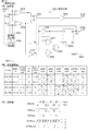
制御信号用、基準信号用、又は、合成信号用の無線信号は、好ましくは、周波数偏移変調方式(FSK:Frequency Shift Keying)で変調されているとよい。FSK方式は、周波数同期がとれればよく、他の方式よりも簡易な回路構成で実現できるし、電力効率の面でも有利である。好ましくは、受信側(周波数復調部)における周波数捕捉範囲に比べて、送信側(周波数変調部)における周波数変動範囲を狭くするとよい。こうすることで、周波数調整を行なわなくても制御信号、基準信号、又は、合成信号の無線伝送を確実に実現できる。 The radio signal for the control signal, the reference signal, or the combined signal is preferably modulated by a frequency shift keying (FSK) method. The FSK method only needs to be frequency-synchronized, can be realized with a simpler circuit configuration than other methods, and is advantageous in terms of power efficiency. Preferably, the frequency fluctuation range on the transmission side (frequency modulation unit) may be narrower than the frequency acquisition range on the reception side (frequency demodulation unit). By doing so, it is possible to reliably realize wireless transmission of the control signal, the reference signal, or the synthesized signal without adjusting the frequency.
合成信号用の無線信号を周波数偏移変調方式とする場合は、信号合成部と信号分離部は、好ましくは次のように構成するとよい。先ず前提として、制御信号及び基準信号の何れもが2値の信号であるとする。信号合成部に関しては、差動増幅回路を設け、その差動入力端の一方に制御信号を入力し、差動入力端の他方には制御信号と基準信号との排他的論理和信号を入力する。こうすることで、差動増幅回路の出力端に3値の合成信号が出力される。この合成信号を周波数偏移変調方式で変調すれば3値FSK信号が得られる。信号分離部に関しては、受信側において3値FSK信号を復調して再生された合成信号と判定用の基準値とを比較する比較部と、比較部の比較結果に基づいて制御信号と基準信号とを生成する論理回路部とを設ける。このような構成にすることで、簡易な構成でありながら、送信側では合成信号用の無線信号としての3値FSK信号を容易に生成することができるし、受信側では再生した合成信号から制御信号と基準信号とを容易に分離できる。 When the radio signal for the combined signal is a frequency shift keying method, the signal combining unit and the signal separating unit are preferably configured as follows. First, it is assumed that both the control signal and the reference signal are binary signals. For the signal synthesis unit, a differential amplifier circuit is provided, and a control signal is input to one of the differential input terminals, and an exclusive OR signal of the control signal and the reference signal is input to the other differential input terminal. . Thus, a ternary composite signal is output to the output terminal of the differential amplifier circuit. If this synthesized signal is modulated by the frequency shift keying method, a ternary FSK signal can be obtained. As for the signal separation unit, a comparison unit that compares the composite signal reproduced by demodulating the ternary FSK signal on the receiving side and a reference value for determination, and a control signal and a reference signal based on the comparison result of the comparison unit And a logic circuit unit for generating With this configuration, the transmission side can easily generate a ternary FSK signal as a radio signal for the synthesized signal, and the receiving side can be controlled from the reproduced synthesized signal. The signal and the reference signal can be easily separated.
好ましくは、再生された合成信号の直流レベルに関わらず適正な分離処理ができるように(つまり判定用の基準値を動的に決定できるように)、信号分離部は、周波数偏移変調方式で変調された無線信号を受信して再生された合成信号における予め定められたレベルを検知するレベル検知部と、レベル検知部の検知結果と、予め定められた式に基づいて判定用の基準値を決定する基準値決定部とを有するとよい。再生された3値の合成信号(復号化データと称する)の最小値、最大値、中間値、振幅(最大値−最小値)との関係においては、判定用の基準値は、最小値と中間値との間の値(好ましくは最小値+振幅/4又は中間値−振幅/4)と、最大値と中間値との間の値(好ましくは最大値−振幅/4又は中間値+振幅/4)の2つが必要になる。各基準値の決定に当たっては、最小値、最大値、中間値の全ての情報についてそれぞれを検知することが考えられるし、振幅はある程度予測できるという点に着目して、最小値、最大値、中間値の何れかを検知することも考えられる。何れの場合も、検知結果とその検知結果に対応した式とに基づいて各基準値を基準値決定部で決める。 Preferably, the signal separation unit uses a frequency shift keying method so that an appropriate separation process can be performed regardless of the DC level of the reproduced composite signal (that is, the determination reference value can be dynamically determined). A level detection unit that detects a predetermined level in a composite signal that is received and reproduced by receiving a modulated radio signal, a detection result of the level detection unit, and a reference value for determination based on a predetermined formula It is good to have the reference value determination part to determine. In the relationship between the minimum value, maximum value, intermediate value, and amplitude (maximum value-minimum value) of the reproduced three-value composite signal (referred to as decoded data), the reference value for determination is the minimum value and the intermediate value. A value between the values (preferably minimum value + amplitude / 4 or intermediate value−amplitude / 4) and a value between the maximum value and the intermediate value (preferably maximum value−amplitude / 4 or intermediate value + amplitude / Two of 4) are necessary. In determining each reference value, it is conceivable to detect all information of the minimum value, maximum value, and intermediate value, and focusing on the fact that the amplitude can be predicted to some extent, the minimum value, maximum value, and intermediate value It is also conceivable to detect any of the values. In any case, each reference value is determined by the reference value determination unit based on the detection result and an expression corresponding to the detection result.
制御信号用、基準信号用、又は、合成信号用の無線信号を伝送対象信号用の無線信号とは別に伝送すればよく、制御信号用、基準信号用、又は、合成信号用を無線伝送するための変調用又は復調用の搬送信号の周波数は、伝送対象信号を無線伝送するための変調用又は復調用の搬送信号の周波数と、同じでもよいし異なっていてもよい。但し、好ましくは、伝送対象信号用の無線信号との間での混変調等の通信障害を確実に防止するべく、これらは伝送対象信号用の無線信号とは異なる搬送周波数で変調されているとよい。 The radio signal for the control signal, the reference signal, or the synthesized signal may be transmitted separately from the radio signal for the transmission target signal, and the control signal, the reference signal, or the synthesized signal may be transmitted by radio. The frequency of the modulation or demodulation carrier signal may be the same as or different from the frequency of the modulation or demodulation carrier signal for wireless transmission of the transmission target signal. However, preferably, these are modulated at a carrier frequency different from the radio signal for the transmission target signal in order to reliably prevent communication failure such as intermodulation with the radio signal for the transmission target signal. Good.
第1の態様及び第3の態様と対応する本実施形態の構成においては、好ましくは、伝送対象信号用の無線信号、及び、制御信号用、基準信号用、又は、合成信号用の無線信号の周波数は、ミリ波帯であるとよい。ミリ波帯とすることの利点に関しては後述する。 In the configuration of the present embodiment corresponding to the first aspect and the third aspect, preferably, a radio signal for a transmission target signal and a radio signal for a control signal, a reference signal, or a composite signal are used. The frequency is preferably in the millimeter wave band. The advantages of using the millimeter wave band will be described later.
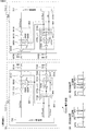
第1の態様及び第3の態様と対応する本実施形態の構成においては、好ましくは、伝送対象信号を無線信号として送信する送信側(第3)の通信装置(伝送対象信号用の送信装置、以下「データ送信装置」と記すこともある)と無線信号を受信して伝送対象信号を再生する受信側(第4)の通信装置(伝送対象信号用の受信装置、以下「データ受信装置」と記すこともある)の内の少なくとも一方を更に備えるとよい。この場合、通常の伝送対象信号用の信号伝送装置を構成するデータ送信装置及びデータ受信装置と、制御信号用の制御信号伝送装置を構成する制御信号送信装置及び制御信号受信装置の組合せとしては、次の3つの態様が代表的である。下記において“「”と“」”とで囲まれた部材が同一の基板(半導体集積回路の基板を含む)上に配される又は同一の筐体内に配される。
1)「データ送信装置+制御信号送信装置」と「データ受信装置+制御信号受信装置」
2)「データ送信装置+制御信号受信装置」と「データ受信装置+制御信号送信装置」
3)「第1のデータ送信装置+第2のデータ受信装置+制御信号送信装置」と「第1のデータ受信装置+第2のデータ送信装置+制御信号受信装置」:第1のデータ送信装置と第1のデータ受信装置との間では第1の伝送対象信号を無線伝送し、第2のデータ送信装置と第2のデータ受信装置との間では第2の伝送対象信号を無線伝送する
In the configuration of the present embodiment corresponding to the first aspect and the third aspect, preferably, a transmission side (third) communication device (transmission target signal transmission device, which transmits a transmission target signal as a radio signal, Hereinafter referred to as “data transmission device”) and a receiving side (fourth) communication device that receives a radio signal and reproduces the transmission target signal (reception device for transmission target signal, hereinafter referred to as “data reception device”) It may be further provided with at least one of them. In this case, as a combination of a data transmission device and a data reception device that constitute a signal transmission device for a normal transmission target signal, and a control signal transmission device and a control signal reception device that constitute a control signal transmission device for a control signal, The following three aspects are typical. In the following, members surrounded by ““ ”and“ ”” are arranged on the same substrate (including a substrate of a semiconductor integrated circuit) or in the same housing.
1) "Data transmitter + control signal transmitter" and "Data receiver + control signal receiver"
2) "Data transmitter + control signal receiver" and "Data receiver + control signal transmitter"
3) “First data transmission device + second data reception device + control signal transmission device” and “first data reception device + second data transmission device + control signal reception device”: first data transmission device The first transmission target signal is wirelessly transmitted between the first data receiving device and the first data receiving device, and the second transmission target signal is wirelessly transmitted between the second data transmitting device and the second data receiving device.
通常の伝送対象信号用の信号伝送装置を構成するデータ送信装置及びデータ受信装置と、制御信号及び基準信号用の制御・基準信号伝送装置を構成する送信側の通信装置(以下「制御・基準信号送信装置」と記すこともある)及び受信側の通信装置(以下「制御・基準信号受信装置」と記すこともある)の組合せとしては、次の3つの態様が代表的である。下記において“「”と“」”とで囲まれた部材が同一の基板(半導体集積回路の基板を含む)上に配される又は同一の筐体内に配される。
1)「データ送信装置+制御・基準信号送信装置」と「データ受信装置+制御・基準信号受信装置」
2)「データ送信装置+制御・基準信号受信装置」と「データ受信装置+制御・基準信号送信装置」
3)「第1のデータ送信装置+第2のデータ受信装置+制御・基準信号送信装置」と「第1のデータ受信装置+第2のデータ送信装置+制御・基準信号受信装置」:第1のデータ送信装置と第1のデータ受信装置との間では第1の伝送対象信号を無線伝送し、第2のデータ送信装置と第2のデータ受信装置との間では第2の伝送対象信号を無線伝送する
A data transmission device and a data reception device that constitute a signal transmission device for a normal transmission target signal, and a transmission side communication device that constitutes a control / reference signal transmission device for a control signal and a reference signal (hereinafter referred to as “control / reference signal”). The following three modes are typical as a combination of a communication device on the receiving side (hereinafter also referred to as “transmission device”) and a communication device on the receiving side (hereinafter also referred to as “control / reference signal reception device”). In the following, members surrounded by ““ ”and“ ”” are arranged on the same substrate (including a substrate of a semiconductor integrated circuit) or in the same housing.
1) "Data transmitter + control / reference signal transmitter" and "Data receiver + control / reference signal receiver"
2) "Data transmitter + control / reference signal receiver" and "Data receiver + control / reference signal transmitter"
3) “First data transmission device + second data reception device + control / reference signal transmission device” and “first data reception device + second data transmission device + control / reference signal reception device”: first The first transmission target signal is wirelessly transmitted between the data transmission device and the first data reception device, and the second transmission target signal is transmitted between the second data transmission device and the second data reception device. Wireless transmission
第1の態様及び第3の態様と対応する本実施形態の構成においては、好ましくは、送受信間の伝送特性が既知であるものとし、伝送対象信号用の送信側の通信装置と受信側の通信装置の少なくとも一方に、設定値に基づいて、予め定められた信号処理を行なう信号処理部と、予め定められた信号処理用の設定値を信号処理部に入力する設定値処理部とを備えるとよい。信号処理部には、変調処理又は復調処理や無線信号用の信号増幅処理も含む。設定値を決める際に、制御信号伝送装置からの制御信号を使用して送信側又は受信側の通信装置を制御するとよい。例えば、1つの筐体内の送信側(第3)の通信装置と受信側(第4)の通信装置の配置位置が変化しない場合(機器内通信の場合)や、送信側の通信装置と受信側の通信装置のそれぞれが各別の筐体内に配置される場合でも使用状態のときの送信側の通信装置と受信側の通信装置の配置位置が予め定められた状態となる場合(比較的近距離の機器間の無線伝送の場合)のように、送受信間の伝送条件が実質的に変化しない(つまり固定である)環境下においては、送信側の通信装置と受信側の通信装置との間の伝送特性を予め知ることができる。 In the configuration of the present embodiment corresponding to the first aspect and the third aspect, it is preferable that the transmission characteristics between transmission and reception are known, and the transmission-side communication apparatus and the reception-side communication for the transmission target signal are assumed. When at least one of the devices includes a signal processing unit that performs predetermined signal processing based on a setting value, and a setting value processing unit that inputs a predetermined setting value for signal processing to the signal processing unit. Good. The signal processing unit includes modulation processing or demodulation processing and signal amplification processing for radio signals. When determining the setting value, it is preferable to control the communication device on the transmission side or the reception side using a control signal from the control signal transmission device. For example, when the arrangement position of the transmission side (third) communication device and the reception side (fourth) communication device in one housing does not change (in the case of in-device communication), the transmission side communication device and the reception side Even when each of the communication devices is placed in a separate case, the placement positions of the transmission-side communication device and the reception-side communication device in the use state are in a predetermined state (relatively short distance). In an environment where the transmission conditions between transmission and reception do not change substantially (that is, are fixed) as in the case of wireless transmission between devices, the communication between the communication device on the transmission side and the communication device on the reception side Transmission characteristics can be known in advance.
送受信間の伝送条件が実質的に変化しない(つまり固定である)環境下においては、信号処理部の動作を規定する設定値を固定値として扱っても、つまり、パラメータ設定を固定にしても、信号処理部を不都合なく動作させることができる。信号処理用の設定値を予め定められた値(つまり固定値)にすることでパラメータ設定を動的に変化させずに済むので、パラメータ演算回路を削減できるし、消費電力を削減することもできる。機器内や比較的近距離の機器間の無線伝送においては通信環境が固定されるため、通信環境に依存する各種回路パラメータを予め決定することができるし、伝送条件が固定である環境下においては、信号処理部の動作を規定する設定値を固定値として扱っても、つまり、パラメータ設定を固定にしても、信号処理部を不都合なく動作させることができる。例えば、工場出荷時に最適なパラメータを求めておき、そのパラメータを装置内部に保持しておくことで、パラメータ演算回路の削減や消費電力の削減を行なうことができる。 In an environment where transmission conditions between transmission and reception do not substantially change (that is, are fixed), even if the setting value that defines the operation of the signal processing unit is treated as a fixed value, that is, even if the parameter setting is fixed, The signal processing unit can be operated without inconvenience. Since the setting value for signal processing is set to a predetermined value (that is, a fixed value), it is not necessary to dynamically change the parameter setting, so that the parameter calculation circuit can be reduced and the power consumption can also be reduced. . In wireless transmission between devices or between devices at relatively short distances, the communication environment is fixed, so various circuit parameters that depend on the communication environment can be determined in advance, and in environments where the transmission conditions are fixed Even if the setting value that defines the operation of the signal processing unit is treated as a fixed value, that is, even if the parameter setting is fixed, the signal processing unit can be operated without any inconvenience. For example, by obtaining optimum parameters at the time of factory shipment and holding the parameters inside the apparatus, it is possible to reduce the parameter arithmetic circuit and power consumption.
信号処理のパラメータ設定としては種々のものがある。例えば、伝送対象信号用の無線信号と制御信号用の無線信号とを別々に伝送する場合との関係では、伝送対象信号用の無線信号の搬送周波数と制御信号用の無線信号の搬送周波数の設定がある。信号処理のパラメータ設定の他の例としては、信号増幅回路(振幅調整部)のゲイン設定(信号振幅設定)や位相調整量の設定や周波数特性の設定等もある。ゲイン設定は、送信電力設定や復調機能部に入力される受信レベル設定や自動利得制御(AGC:Automatic Gain Control)等に利用されるし、位相調整量の設定は、制御信号や基準信号を別送する系で送信信号の遅延量に合わせて位相を調整する場合に利用されるし、周波数特性の設定は、送信側で予め低域周波数成分や高域周波数成分の振幅を強調する場合に利用される。 There are various signal processing parameter settings. For example, in the case where the radio signal for the transmission target signal and the radio signal for the control signal are transmitted separately, the carrier frequency of the radio signal for the transmission target signal and the carrier frequency of the radio signal for the control signal are set. There is. Other examples of signal processing parameter setting include gain setting (signal amplitude setting) of a signal amplification circuit (amplitude adjustment unit), setting of a phase adjustment amount, setting of frequency characteristics, and the like. The gain setting is used for transmission power setting, reception level setting input to the demodulation function section, automatic gain control (AGC), etc., and the phase adjustment amount is set by sending a control signal and a reference signal separately. Is used when adjusting the phase according to the delay amount of the transmission signal in the system, and the setting of the frequency characteristics is used when emphasizing the amplitude of the low frequency component and high frequency component in advance on the transmission side. The
例えば、第1の構成として、設定値決定部と、設定値記憶部と、動作制御部とを具備した設定値処理部を基板上に設ける。設定値決定部は、半導体チップの各機能部の動作を指定するための「信号処理用の設定値」(変数、パラメータ)を決定する。設定値を決定する処理は、例えば、工場での製品出荷時に行なう。設定値記憶部は、設定値決定部により決定された設定値を記憶する。動作制御部は、設定値記憶部から読み出した設定値に基づいて信号処理部が形成された半導体チップの各機能部(例えば、変調部又は復調部、周波数変換部、無線信号用の増幅部等)を動作させる。設定値処理部が配される基板は半導体チップ用の基板と同じであることが好ましいが、このことは必須でない。更には、設定値処理部は半導体チップの外部に備えてもよいが、好ましくは半導体チップに内蔵するとよく、この場合は、設定値処理部は制御対象となる各機能部(変調部又は復調部、周波数変換部、増幅部等)が搭載されている基板と同一の基板に搭載されることになる。 For example, as a first configuration, a setting value processing unit including a setting value determining unit, a setting value storage unit, and an operation control unit is provided on the substrate. The set value determining unit determines “set values for signal processing” (variables, parameters) for designating the operation of each functional unit of the semiconductor chip. The process for determining the set value is performed, for example, when the product is shipped at the factory. The set value storage unit stores the set value determined by the set value determining unit. The operation control unit is a functional unit (for example, a modulation unit or a demodulation unit, a frequency conversion unit, a radio signal amplification unit, etc.) of the semiconductor chip on which the signal processing unit is formed based on the setting value read from the setting value storage unit. ). The substrate on which the set value processing unit is arranged is preferably the same as the substrate for the semiconductor chip, but this is not essential. Furthermore, the set value processing unit may be provided outside the semiconductor chip, but is preferably built in the semiconductor chip. In this case, the set value processing unit is a function unit (modulation unit or demodulation unit) to be controlled. , Frequency conversion unit, amplification unit, etc.) are mounted on the same substrate.
又、第2の構成として、装置外部にて決定された設定値を記憶する構成にすることも考えられる。この場合、設定値決定部に代えて入出力インタフェース部を設ける。入出力インタフェース部は、設定値を外部から受け付ける設定値受付部の一例である。入出力インタフェース部は、設定値記憶部との間のインタフェース機能をなし、外部から与えられる設定値を設定値記憶部に記憶し、又、設定値記憶部に記憶されている設定値を読み出して外部に出力する。第2の構成の場合、設定値処理部にて設定値を決定するのではなく、外部にて設定値を決定する。例えば、設計パラメータと実機の状態から設定値を決定してもよいし、装置の実働試験に基づいて設定値を決定してもよい。又、何れの場合も、装置ごとに個別の設定値を決定するのではなく、各装置に共通の設定値を決定してもよい。設計パラメータから設定値を決定する場合は、概ねこの場合に該当するし、標準の装置での実働試験に基づいて設定値を決定する場合も、この場合に該当する。 Further, as a second configuration, a configuration in which a set value determined outside the apparatus is stored may be considered. In this case, an input / output interface unit is provided instead of the set value determination unit. The input / output interface unit is an example of a setting value receiving unit that receives a setting value from the outside. The input / output interface unit has an interface function with the setting value storage unit, stores setting values given from the outside in the setting value storage unit, and reads out setting values stored in the setting value storage unit Output to the outside. In the case of the second configuration, the setting value is not determined by the setting value processing unit, but is determined externally. For example, the set value may be determined from the design parameters and the actual machine state, or the set value may be determined based on an actual operation test of the apparatus. In any case, a setting value common to each apparatus may be determined instead of determining an individual setting value for each apparatus. The case where the set value is determined from the design parameters generally corresponds to this case, and the case where the set value is determined based on an actual test with a standard apparatus also corresponds to this case.
[電子機器]
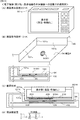
第2の態様と対応する本実施形態の電子機器においては、各部がひとつの筐体内に収容された状態の装置構成で1つの電子機器とすることもできるし、複数の装置(電子機器)の組合せで1つの電子機器の全体が構成されることもある。本実施形態の信号伝送装置は、例えば、デジタル記録再生装置、地上波テレビ受像装置、携帯電話装置、ゲーム装置、コンピュータ等の電子機器において使用される。
[Electronics]
In the electronic device according to the present embodiment corresponding to the second aspect, each device can be configured as one electronic device in a state in which each unit is accommodated in one casing, or a plurality of devices (electronic devices) An entire electronic device may be configured in combination. The signal transmission device of this embodiment is used in electronic devices such as a digital recording / reproducing device, a terrestrial television receiver, a mobile phone device, a game device, and a computer.
各部がひとつの筐体内に収容された状態の装置構成で1つの電子機器とする場合であれば、制御信号を無線信号として送信する第1の装置と、第1の通信装置から送信された無線信号を受信して制御信号を再生する第2の通信装置と、伝送対象信号を送信する送信装置と、送信装置から送信された無線信号を受信して伝送対象信号を再生する受信装置と、を1つの筐体内に備える構成にする。又は、複数の装置(電子機器)の組合せで1つの電子機器の全体を構成する場合であれば、伝送対象信号を送信する送信装置と送信装置から送信された無線信号を受信して伝送対象信号を再生する受信装置の内の少なくとも一方と、送信装置又は受信装置の送受信の相手方となる方を制御するための制御信号を無線信号として送信する第1の通信装置とを、1つの筐体内に配して第1の電子機器を個性する。又、第1の電子機器における送信装置の通信の相手方となる受信装置又は第1の電子機器における受信装置の通信の相手方となる送信装置と、第1の通信装置から送信された無線信号を受信して制御信号を再生する第2の通信装置とを、1つの筐体内に配置して第2の電子機器を構成する。そして、第1の電子機器と第2の電子機器との間で伝送対象信号を無線信号で伝送する。電子機器が何れの構成であっても、制御信号用の送信側(第1)の通信装置は、伝送対象信号を無線信号として送信する第3の通信装置と第3の通信装置から送信された無線信号を受信して伝送対象信号を再生する第4の通信装置の内の少なくとも一方に制御信号供給し、制御信号用の受信側(第2)の通信装置は、再生した制御信号を第3の通信装置又は第4の通信装置に供給するする。そして、この場合において、制御信号用の無線信号を、送信装置と受信装置との間における伝送対象信号用の無線信号とは別に伝送する。 If the device configuration is such that each unit is housed in one housing, the electronic device is a first device that transmits a control signal as a wireless signal, and the wireless device that is transmitted from the first communication device. A second communication device that receives the signal and reproduces the control signal; a transmission device that transmits the transmission target signal; and a reception device that receives the radio signal transmitted from the transmission device and reproduces the transmission target signal. A configuration is provided in one housing. Alternatively, in the case of configuring an entire electronic device by combining a plurality of devices (electronic devices), a transmission device that transmits a transmission target signal and a radio signal transmitted from the transmission device and a transmission target signal And a first communication device that transmits, as a radio signal, a control signal for controlling a transmission device or a counterpart of a transmission / reception device of the reception device in a single housing. To personalize the first electronic device. In addition, a receiving device that is a counterpart of communication of the transmitting device in the first electronic device or a transmitting device that is a counterpart of communication of the receiving device in the first electronic device and a radio signal transmitted from the first communication device are received. Then, the second communication device that reproduces the control signal is arranged in one housing to constitute the second electronic device. Then, the transmission target signal is transmitted as a radio signal between the first electronic device and the second electronic device. Regardless of the configuration of the electronic device, the transmission device (first) communication device for the control signal is transmitted from the third communication device and the third communication device that transmit the transmission target signal as a radio signal. A control signal is supplied to at least one of the fourth communication devices that receives the radio signal and reproduces the transmission target signal, and the receiving device (second) communication device for the control signal outputs the reproduced control signal to the third communication device. To the communication device or the fourth communication device. In this case, the control signal radio signal is transmitted separately from the transmission target signal radio signal between the transmission device and the reception device.
以下で説明する本実施形態の信号伝送装置や電子機器では、ミリ波帯(波長が1〜10ミリメートル)の搬送周波数を主に使用するものとして説明するが、ミリ波帯に限らず、より波長の短い例えばサブミリ波帯(波長が0.1〜1ミリメートル)やより波長の長いセンチ波帯(波長が1〜10センチメートル)等、ミリ波帯近傍の搬送周波数を使用する場合にも適用可能である。例えば、ミリ波帯だけでは要求される通信帯域を確保できないときには、サブミリ波帯〜ミリ波帯、ミリ波帯〜センチ波帯、又はサブミリ波帯〜ミリ波帯〜センチ波帯を使用する。 In the signal transmission device and the electronic device of the present embodiment described below, the carrier frequency in the millimeter wave band (wavelength is 1 to 10 millimeters) will be mainly used. Also applicable when using carrier frequencies near the millimeter wave band, such as sub-millimeter wave band (wavelength is 0.1 to 1 millimeter) and longer wavelength centimeter wave band (wavelength is 1 to 10 centimeter). It is. For example, when a required communication band cannot be ensured only by the millimeter wave band, a sub millimeter wave band to a millimeter wave band, a millimeter wave band to a centimeter wave band, or a sub millimeter wave band to a millimeter wave band to a centimeter wave band is used.
通信装置を構成する場合、送信側の通信装置が単独の場合と、受信側の通信装置が単独の場合と、送信側と受信側の双方の通信装置を有する場合とがある。送信側と受信側は無線信号伝送路(例えばミリ波信号伝送路)を介して結合されミリ波帯で信号伝送を行なうように構成される。伝送対象の信号を広帯域伝送に適したミリ波帯域に周波数変換して伝送する。但し、如何なる場合でも、送信側の通信装置と受信側の通信装置の組(対)で、信号伝送装置を構成する。そして、比較的近距離に配置された送信側の通信装置と受信側の通信装置の間では、伝送対象の信号をミリ波信号に変換してから、このミリ波信号をミリ波信号伝送路を介して伝送する。本実施形態の「無線伝送」とは、信号を一般的な電気配線(単純なワイヤー配線)ではなく無線(電波:この例ではミリ波)で伝送することを意味する。 When configuring the communication device, there are a case where the communication device on the transmission side is single, a case where the communication device on the reception side is single, and a case where both the communication devices on the transmission side and the reception side are included. The transmitting side and the receiving side are coupled via a radio signal transmission path (for example, a millimeter wave signal transmission path) and configured to perform signal transmission in the millimeter wave band. The signal to be transmitted is frequency-converted to a millimeter wave band suitable for broadband transmission and transmitted. However, in any case, a signal transmission device is configured by a pair (pair) of a communication device on the transmission side and a communication device on the reception side. Then, between the communication device on the transmission side and the communication device on the reception side that are disposed at a relatively short distance, the signal to be transmitted is converted into a millimeter wave signal, and then this millimeter wave signal is transmitted through the millimeter wave signal transmission path. Transmitted through. The term “wireless transmission” in the present embodiment means that a signal is transmitted wirelessly (radio wave: millimeter wave in this example) instead of general electric wiring (simple wire wiring).
「比較的近距離」とは、放送や一般的な無線通信で使用される野外(屋外)での通信装置間の距離に比べて距離が短いことを意味し、伝送範囲が閉じられた空間として実質的に特定できる程度のものであればよい。「閉じられた空間」とは、その空間内部から外部への電波の漏れが少なく、逆に、外部から空間内部への電波の到来(侵入)が少ない状態の空間を意味し、典型的にはその空間全体が電波に対して遮蔽効果を持つ筐体(ケース)で囲まれた状態である。例えば、1つの電子機器の筐体内での基板間通信や同一基板上でのチップ間通信や、一方の電子機器に他方の電子機器が装着された状態のように複数の電子機器が一体となった状態での機器間の通信が該当する。「一体」は、装着によって両電子機器が完全に接触した状態が典型例であるが、両電子機器間の伝送範囲が閉じられた空間として実質的に特定できる程度のものであればよい。例えば数センチ以内又は10数センチ以内等、比較的近距離で、両電子機器が多少離れた状態で定められた位置に配置されていて「実質的に」一体と見なせる場合も含む。要するに、両電子機器で構成される電波が伝搬し得る空間内部から外部への電波の漏れが少なく、逆に、外部からその空間内部への電波の到来(侵入)が少ない状態であればよい。 “Relatively close” means that the distance is short compared to the distance between communication devices in the outdoors (outdoors) used in broadcasting and general wireless communication, and the transmission range is closed. Any material that can be substantially specified may be used. “Closed space” means a space where there is little leakage of radio waves from the inside of the space to the outside, and conversely, there is little arrival (intrusion) of radio waves from the outside to the inside of the space. The entire space is surrounded by a casing (case) that has a shielding effect against radio waves. For example, a plurality of electronic devices are integrated, such as inter-board communication within a housing of one electronic device, inter-chip communication on the same substrate, or a state in which the other electronic device is mounted on one electronic device. This corresponds to communication between devices in a connected state. The “integrated” is typically a state in which both electronic devices are completely in contact with each other, but it may be of a level that can be substantially specified as a space in which the transmission range between the two electronic devices is closed. For example, it includes a case where both electronic devices are disposed at a predetermined position at a relatively short distance, such as within a few centimeters or within a few tens of centimeters, and can be regarded as being “substantially” integral. In short, it suffices if there is little leakage of radio waves from the inside to the outside where radio waves composed of both electronic devices can propagate, and conversely, there is little arrival (intrusion) of radio waves from outside to the inside of the space.
1つの電子機器の筐体内での信号伝送を機器(又は筐体)内信号伝送と称し、複数の電子機器が一体(以下、「実質的に一体」も含む)となった状態での信号伝送を機器間信号伝送と称する。機器内信号伝送の場合は、送信側の通信装置(通信部:送信部)と受信側の通信装置(通信部:受信部)が同一筐体内に収容され、通信部(送信部と受信部)間に無線信号伝送路が形成された信号伝送装置が電子機器そのものとなり得る。一方、機器間信号伝送の場合、送信側の通信装置(通信部:送信部)と受信側の通信装置(通信部:受信部)がそれぞれ異なる電子機器の筐体内に収容され、両電子機器が定められた位置に配置され一体となったときに両電子機器内の通信部(送信部と受信部)間に無線信号伝送路が形成されて信号伝送装置が構築される。 Signal transmission within the housing of one electronic device is referred to as signal transmission within the device (or housing), and signal transmission in a state in which a plurality of electronic devices are integrated (hereinafter also including “substantially integrated”). Is called inter-device signal transmission. In the case of in-device signal transmission, the communication device (communication unit: transmission unit) on the transmission side and the communication device (communication unit: reception unit) on the reception side are accommodated in the same housing, and the communication unit (transmission unit and reception unit) A signal transmission device in which a wireless signal transmission path is formed therebetween can be an electronic device itself. On the other hand, in the case of signal transmission between devices, the communication device on the transmission side (communication unit: transmission unit) and the communication device on the reception side (communication unit: reception unit) are accommodated in different electronic device casings, and both electronic devices are A radio signal transmission path is formed between communication units (transmission unit and reception unit) in both electronic devices when they are arranged at a predetermined position and integrated with each other, thereby constructing a signal transmission device.
ミリ波信号伝送路を挟んで設けられる各通信装置においては、送信系統と受信系統が対となって組み合わされて配置される。各通信装置に送信系統と受信系統を併存させることで双方向通信ができる。各通信装置に送信系統と受信系統を併存させる場合、一方の通信装置と他方の通信装置との間の信号伝送は片方向(一方向)のものでもよいし双方向のものでもよい。例えば、第1の通信装置が送信側となり第2の通信装置が受信側となる場合には、第1の通信装置に送信機能をなす第1の通信部が配置され第2の通信装置に受信機能をなす第2の通信部が配置される。第2の通信装置が送信側となり第1の通信装置が受信側となる場合には、第2の通信装置に送信機能をなす第1の通信部が配置され第1の通信装置に受信機能をなす第2の通信部が配置される。 In each communication device provided across the millimeter wave signal transmission path, a transmission system and a reception system are paired and arranged. Two-way communication can be performed by causing each communication device to have both a transmission system and a reception system. When transmitting and receiving systems coexist in each communication device, signal transmission between one communication device and the other communication device may be one-way (one-way) or two-way. For example, when the first communication device is a transmission side and the second communication device is a reception side, a first communication unit that performs a transmission function is arranged in the first communication device and is received by the second communication device. A second communication unit having a function is arranged. When the second communication device is a transmission side and the first communication device is a reception side, a first communication unit that performs a transmission function is arranged in the second communication device, and the first communication device has a reception function. A second communication unit is arranged.
第1の通信部は、例えば、伝送対象の信号を信号処理してミリ波帯の電気信号を生成する送信側の信号生成部(伝送対象の電気信号をミリ波帯の電気信号に変換する信号変換部)と、ミリ波帯の無線信号を伝送する無線信号伝送路(例えばミリ波信号伝送路)に送信側の信号生成部で生成されたミリ波帯の電気信号を結合させる送信側の信号結合部を送信部に備えるものとする。好ましくは、送信側の信号生成部は、伝送対象の信号を生成する機能部と一体であるのがよい。 The first communication unit is, for example, a signal generator on the transmission side that performs signal processing on a transmission target signal to generate a millimeter wave band electrical signal (a signal that converts a transmission target electrical signal into a millimeter wave band electrical signal). Converter) and a signal on the transmission side that couples the millimeter-wave band electrical signal generated by the signal generation unit on the transmission side to a radio signal transmission path (for example, a millimeter-wave signal transmission path) that transmits a millimeter-wave band radio signal Assume that the transmitter is provided with a coupling unit. Preferably, the signal generator on the transmission side is integrated with a functional unit that generates a signal to be transmitted.
例えば、送信側の信号生成部は変調回路(変調部)を有し、変調回路が伝送対象の信号(ベースバンド信号)を変調する。送信側の信号生成部は変調回路によって変調された後の信号を周波数変換してミリ波帯の電気信号を生成する。原理的には、伝送対象の信号をダイレクトにミリ波帯の電気信号に変換してもよい。送信側の信号結合部は、送信側の信号生成部によって生成されたミリ波帯の電気信号を無線信号(電磁波、電波)に変換して無線信号伝送路としてのミリ波信号伝送路に供給する。 For example, the signal generator on the transmission side includes a modulation circuit (modulation unit), and the modulation circuit modulates a signal to be transmitted (baseband signal). The signal generator on the transmission side converts the frequency of the signal after being modulated by the modulation circuit to generate an electrical signal in the millimeter wave band. In principle, a signal to be transmitted may be directly converted into a millimeter wave band electrical signal. The signal coupling unit on the transmission side converts the millimeter-wave band electrical signal generated by the signal generation unit on the transmission side into a radio signal (electromagnetic wave, radio wave) and supplies it to the millimeter wave signal transmission path as a radio signal transmission path .
第2の通信部は例えば、無線信号伝送路としてのミリ波信号伝送路を介して伝送されてきたミリ波帯の無線信号を受信し電気信号に変換する受信側の信号結合部を受信部に備えるとともに、受信側の信号結合部により受信され電気信号に変換されたミリ波帯の電気信号(入力信号)を信号処理して通常の電気信号(伝送対象の信号、ベースバンド信号)を生成(復元、再生)する受信側の信号生成部(ミリ波の信号を伝送対象の電気信号に変換する信号変換部)を備えるものとする。好ましくは、受信側の信号生成部は、伝送対象の信号を受け取る機能部と一体であるのがよい。例えば、受信側の信号生成部は復調回路(復調部)を有し、ミリ波帯の電気信号を周波数変換して出力信号を生成し、その後、復調回路が出力信号を復調することで伝送対象の信号を生成する。原理的には、ミリ波帯の電気信号からダイレクトに伝送対象の信号に変換してもよい。 For example, the second communication unit receives, as a reception unit, a signal coupling unit on the reception side that receives a millimeter-wave band radio signal transmitted via a millimeter-wave signal transmission path as a radio signal transmission path and converts the radio signal into an electrical signal. In addition, the millimeter waveband electrical signal (input signal) received by the signal coupling unit on the receiving side and converted into an electrical signal is processed to generate a normal electrical signal (signal to be transmitted, baseband signal) ( It is assumed that a signal generation unit on the reception side (restoration and reproduction) (a signal conversion unit that converts a millimeter wave signal into an electric signal to be transmitted) is provided. Preferably, the signal generation unit on the reception side is integrated with a function unit that receives a signal to be transmitted. For example, the signal generation unit on the receiving side has a demodulation circuit (demodulation unit), generates an output signal by converting the frequency of an electrical signal in the millimeter wave band, and then the demodulation circuit demodulates the output signal to be transmitted. Generate a signal. In principle, a millimeter wave band electrical signal may be directly converted into a signal to be transmitted.
つまり、信号インタフェースをとるに当たり、伝送対象の信号に関して、無線信号により接点レスやケーブルレスで伝送する(電気配線での伝送でない)。好ましくは、少なくとも信号伝送(特に高速伝送や大容量伝送が要求される映像信号や高速のクロック信号等)に関しては、ミリ波帯等の無線信号により伝送する。要するに、従前は電気配線によって行なわれていた信号伝送を本実施例では無線信号(電波)により行なう。ミリ波帯等の無線信号で信号伝送を行なうことで、ギガビット毎秒〔Gbps〕オーダーの高速信号伝送を実現することができるし、無線信号の及ぶ範囲を容易に制限でき、この性質に起因する効果も得られる。 In other words, when taking the signal interface, the signal to be transmitted is transmitted by wireless signals without contact or cable (not transmitted by electrical wiring). Preferably, at least signal transmission (especially a video signal or high-speed clock signal that requires high-speed transmission or large-capacity transmission) is transmitted by a radio signal such as a millimeter wave band. In short, signal transmission that has been performed by electrical wiring in the past is performed by radio signals (radio waves) in this embodiment. By performing signal transmission with a radio signal in the millimeter wave band or the like, high-speed signal transmission in the order of gigabit per second [Gbps] can be realized, and the range covered by the radio signal can be easily limited. Can also be obtained.
ここで、各信号結合部は、第1の通信部と第2の通信部が無線信号伝送路(例えばミリ波信号伝送路)を介して無線信号(ここではミリ波帯の無線信号)が伝送可能となるようにするものであればよい。例えばアンテナ構造(アンテナ結合部)を備えるものとしてもよいし、アンテナ構造を具備せずに結合をとるものでもよい。「ミリ波の信号を伝送するミリ波信号伝送路」等の無線信号伝送路は、空気(いわゆる自由空間)であってもよいが、好ましくは、無線信号(電磁波、電波)を伝送路中に閉じ込めつつ無線信号を伝送させる構造(無線信号閉込め構造、例えばミリ波閉込め構造)を持つものがよい。無線信号閉込め構造を積極的に利用することで、例えば電気配線のように無線信号伝送路の引回しを任意に確定することができる。このような無線信号閉込め構造のものとしては、例えば、典型的にはいわゆる導波管が該当するが、これに限らない。例えば、無線信号を伝送可能な誘電体素材で構成されたもの(誘電体伝送路や無線信号誘電体内伝送路と称する)や、伝送路を構成し、かつ、無線信号の外部放射を抑える遮蔽材が伝送路を囲むように設けられその遮蔽材の内部が中空の中空導波路がよい。誘電体素材や遮蔽材に柔軟性を持たせることで無線信号伝送路の引回しが可能となる。空気(いわゆる自由空間)の場合、各信号結合部はアンテナ構造をとることになり、そのアンテナ構造によって近距離の空間中を信号伝送することになる。一方、誘電体素材で構成されたものとする場合は、アンテナ構造をとることもできるが、そのことは必須でない。 Here, in each signal coupling unit, the first communication unit and the second communication unit transmit a radio signal (in this case, a millimeter wave band radio signal) via a radio signal transmission path (for example, a millimeter wave signal transmission path). Anything that makes it possible is acceptable. For example, it may be provided with an antenna structure (antenna coupling portion), or may be coupled without an antenna structure. A wireless signal transmission path such as “millimeter wave signal transmission path for transmitting a millimeter wave signal” may be air (so-called free space), but preferably a wireless signal (electromagnetic wave, radio wave) is transmitted into the transmission path. What has a structure (wireless signal confinement structure, for example, millimeter wave confinement structure) which transmits a radio signal while confining is good. By actively using the radio signal confinement structure, it is possible to arbitrarily determine the routing of the radio signal transmission path, such as electrical wiring. As such a radio signal confinement structure, for example, a so-called waveguide is typically applicable, but it is not limited thereto. For example, a material made of a dielectric material capable of transmitting a wireless signal (referred to as a dielectric transmission line or a wireless signal dielectric transmission line), or a shielding material that constitutes a transmission line and suppresses external radiation of the wireless signal. Is preferably provided so as to surround the transmission line, and the inside of the shielding material is hollow. By giving flexibility to the dielectric material and the shielding material, the wireless signal transmission path can be routed. In the case of air (so-called free space), each signal coupling portion has an antenna structure, and signals are transmitted in a short-distance space by the antenna structure. On the other hand, when it is assumed that it is made of a dielectric material, an antenna structure can be taken, but this is not essential.
[電気配線による信号伝送と無線伝送との対比]
電気配線を介して信号伝送を行なう場合は、次のような問題がある。
i)伝送データの大容量・高速化が求められるが、電気配線の伝送速度・伝送容量には限界がある。
ii)伝送データの高速化の問題に対応するため、配線数を増やして、信号の並列化により一信号線当たりの伝送速度を落とす手法がある。しかしながら、この手法では、入出力端子の増大に繋がってしまう。その結果、プリント基板やケーブル配線の複雑化、コネクタ部や電気的インタフェースの物理サイズの増大等が求められ、それらの形状が複雑化し、これらの信頼性が低下し、コストが増大する等の問題が起こる。
iii)映画映像やコンピュータ画像等の情報量の膨大化に伴い、ベースバンド信号の帯域が広くなるに従って、EMC(電磁環境適合性)の問題がより顕在化してくる。例えば、電気配線を用いた場合は、配線がアンテナとなって、アンテナの同調周波数に対応した信号が干渉される。又、配線のインピーダンスの不整合等による反射や共振によるものも不要輻射の原因となる。このような問題を対策するために、電子機器の構成が複雑化する。
iv)EMCの他に、反射があると受信側でシンボル間での干渉による伝送エラーや妨害の飛び込みによる伝送エラーも問題となってくる。
[Contrast between signal transmission by electric wiring and wireless transmission]
When performing signal transmission through electrical wiring, there are the following problems.
i) Large capacity and high speed of transmission data are required, but there are limits to the transmission speed and capacity of electrical wiring.
ii) In order to cope with the problem of high-speed transmission data, there is a method of increasing the number of wires and reducing the transmission speed per signal line by parallelizing signals. However, this method leads to an increase in input / output terminals. As a result, complicated printed circuit boards and cable wiring, increased physical size of connectors and electrical interfaces, etc. are required, their shapes become complicated, their reliability decreases, and costs increase. Happens.
iii) With the increase in the amount of information such as movie images and computer images, the problem of EMC (electromagnetic compatibility) becomes more apparent as the band of the baseband signal becomes wider. For example, when electrical wiring is used, the wiring becomes an antenna, and a signal corresponding to the tuning frequency of the antenna is interfered. Also, reflections and resonances due to wiring impedance mismatch and the like also cause unnecessary radiation. In order to cope with such a problem, the configuration of the electronic device is complicated.
iv) In addition to EMC, if there is reflection, a transmission error due to interference between symbols on the receiving side or a transmission error due to jumping in interference will also become a problem.
これに対して、電気配線ではなく無線(例えばミリ波帯を使用)で信号伝送を行なう場合、配線形状やコネクタの位置を気にする必要がないため、レイアウトに対する制限があまり発生しない。ミリ波による信号伝送に置き換えた信号については配線や端子を割愛できるので、EMCの問題から解消される。一般に、通信装置内部で他にミリ波帯の周波数を使用している機能部は存在しないため、EMCの対策が容易に実現できる。送信側の通信装置と受信側の通信装置を近接した状態での無線伝送となり、固定位置間や既知の位置関係の信号伝送であるため、次のような利点が得られる。
1)送信側と受信側の間の伝搬チャネル(導波構造)を適正に設計することが容易である。
2)送信側と受信側を封止する伝送路結合部の誘電体構造と伝搬チャネル(ミリ波信号伝送路の導波構造)を併せて設計することで、自由空間伝送より、信頼性の高い良好な伝送が可能になる。
3)無線伝送を管理するコントローラの制御も一般の無線通信のように動的にアダプティブに頻繁に行なう必要はないため、制御によるオーバーヘッドを一般の無線通信に比べて小さくすることができる。その結果、制御回路や演算回路等で使用する設定値 (いわゆるパラメータ)を定数(いわゆる固定値)にすることができ、小型、低消費電力、高速化が可能になる。例えば、製造時や設計時に無線伝送特性を校正し、個体のばらつき等を把握すれば、そのデータを参照できるので、信号処理部の動作を規定する設定値は、プリセットや静的な制御にできる。その設定値は信号処理部の動作を概ね適正に規定するから、簡易な構成かつ低消費電力でありながら、高品位の通信が可能になる。
On the other hand, when signal transmission is performed wirelessly (for example, using a millimeter wave band) instead of electrical wiring, there is no need to worry about the wiring shape and connector position, so that there are not many restrictions on the layout. For signals replaced with signal transmission by millimeter waves, wiring and terminals can be omitted, which eliminates the problem of EMC. In general, there is no other functional unit that uses a millimeter-wave band frequency inside the communication device, so that EMC countermeasures can be easily realized. Wireless transmission is performed in a state in which the communication device on the transmission side and the communication device on the reception side are close to each other, and signal transmission is performed between fixed positions or in a known positional relationship. Therefore, the following advantages are obtained.
1) It is easy to properly design a propagation channel (waveguide structure) between the transmission side and the reception side.
2) Higher reliability than free space transmission by designing the dielectric structure of the transmission line coupling part that seals the transmission side and the reception side and the propagation channel (waveguide structure of the millimeter wave signal transmission line) together Good transmission is possible.
3) Since the controller for managing the wireless transmission does not need to be dynamically and frequently controlled as in general wireless communication, the overhead due to control can be reduced as compared with general wireless communication. As a result, a set value (so-called parameter) used in a control circuit, an arithmetic circuit, or the like can be made a constant (so-called fixed value), and miniaturization, low power consumption, and high speed can be achieved. For example, if the wireless transmission characteristics are calibrated at the time of manufacture or design and the individual variations are grasped, the data can be referred to. Therefore, the setting values that define the operation of the signal processing unit can be preset or statically controlled. . Since the set value prescribes the operation of the signal processing unit appropriately, high-quality communication is possible while having a simple configuration and low power consumption.
又、波長の短いミリ波帯での無線通信にすることで、次のような利点が得られる。
a)ミリ波通信は通信帯域を広く取れるため、データレートを大きくとることが簡単にできる。
b)伝送に使う周波数が他のベースバンド信号処理の周波数から離すことができ、ミリ波とベースバンド信号の周波数の干渉が起こり難い。
c)ミリ波帯は波長が短いため、波長に応じてきまるアンテナや導波構造を小さくできる。加えて、距離減衰が大きく回折も少ないため電磁シールドが行ない易い。
d)通常の野外での無線通信では、搬送波の安定度については、干渉等を防ぐため、厳しい規制がある。そのような安定度の高い搬送波を実現するためには、高い安定度の外部周波数基準部品と逓倍回路やPLL(位相同期ループ回路)等が用いられ、回路規模が大きくなる。しかしながら、ミリ波は(特に固定位置間や既知の位置関係の信号伝送との併用時は)、容易に遮蔽でき、外部に漏れないようにできる。安定度を緩めた搬送波で伝送された信号を受信側で小さい回路で復調するのには、注入同期方式を採用するのが好適である。
Moreover, the following advantages can be obtained by using wireless communication in the millimeter-wave band with a short wavelength.
a) Since the millimeter wave communication can take a wide communication band, it is easy to increase the data rate.
b) The frequency used for transmission can be separated from the frequency of other baseband signal processing, and interference between the millimeter wave and the frequency of the baseband signal hardly occurs.
c) Since the millimeter wave band has a short wavelength, it is possible to reduce the size of an antenna or a waveguide structure depending on the wavelength. In addition, since the distance attenuation is large and the diffraction is small, electromagnetic shielding is easy to perform.
d) In normal outdoor wireless communication, the stability of a carrier wave has strict regulations to prevent interference and the like. In order to realize such a highly stable carrier wave, a highly stable external frequency reference component, a multiplier circuit, a PLL (phase locked loop circuit), and the like are used, which increases the circuit scale. However, millimeter waves can be easily shielded (especially when used in combination with signal transmission between fixed positions or with a known positional relationship) and can be prevented from leaking outside. In order to demodulate a signal transmitted by a carrier wave having a low stability with a small circuit on the receiving side, it is preferable to adopt an injection locking method.
例えば、比較的近距離(例えば10数センチ以内)に配置されている電子機器間や電子機器内での高速信号伝送を実現する手法として、例えばLVDS(Low Voltage Differential Signaling)が知られている。しかしながら、最近のさらなる伝送データの大容量高速化に伴い、消費電力の増加、反射等による信号歪みの影響の増加、不要輻射の増加(いわゆるEMIの問題)、等が問題となる。例えば、映像信号(撮像信号を含む)やコンピュータ画像等の信号を機器内や機器間で高速(リアルタイム)に伝送する場合にLVDSでは限界に達してきている。データの高速伝送に対応するため、配線数を増やして、信号の並列化により一信号線当たりの伝送速度を落としてもよい。しかしながら、この対処では、入出力端子の増大に繋がってしまう。その結果、プリント基板やケーブル配線の複雑化や半導体チップサイズの拡大等が求められる。又、高速・大容量のデータを配線で引き回すことでいわゆる電磁界障害が問題となる。 For example, LVDS (Low Voltage Differential Signaling) is known as a technique for realizing high-speed signal transmission between electronic devices arranged within a relatively short distance (for example, within a few tens of centimeters) or within an electronic device. However, with the recent increase in transmission data capacity and speed, there are problems such as increased power consumption, increased signal distortion due to reflection and the like, increased unwanted radiation (so-called EMI problem), and the like. For example, LVDS has reached its limit when signals such as video signals (including imaging signals) and computer images are transmitted at high speed (in real time) between devices or between devices. In order to support high-speed data transmission, the number of wires may be increased and the transmission speed per signal line may be reduced by parallelizing signals. However, this countermeasure leads to an increase in input / output terminals. As a result, it is required to increase the complexity of the printed circuit board and the cable wiring and to increase the semiconductor chip size. Also, so-called electromagnetic field interference becomes a problem when high-speed and large-capacity data is routed by wiring.
LVDSや配線数を増やす手法における問題は何れも、電気配線により信号を伝送することに起因している。そこで、電気配線により信号を伝送することに起因する問題を解決する手法として、電気配線を無線化して伝送する手法(特に電波で信号伝送を行なう手法)を採ってもよい。電気配線を無線化して伝送する手法としては例えば、筐体内の信号伝送を無線で行なうとともに、UWB(Ultra Wide Band )通信方式を適用してもよいし(第1の手法と記す)、波長の短い(1〜10ミリメートル)ミリ波帯の搬送周波数を使用してもよい(第2の手法と記す)。しかしながら、第1の手法のUWB通信方式では、搬送周波数が低く、例えば映像信号を伝送するような高速通信に向かないし、アンテナが大きくなる等、サイズ上の問題がある。更に、伝送に使う周波数が他のベースバンド信号処理の周波数に近いため、無線信号とベースバンド信号との間で干渉が起こり易いという問題点もある。又、搬送周波数が低い場合は、機器内の駆動系ノイズの影響を受け易く、その対処が必要になる。これに対して、第2の手法のように、より波長の短いミリ波帯の搬送周波数を使用すると、アンテナサイズや干渉の問題を解決し得る。 Any problems in the LVDS or the method of increasing the number of wirings are caused by transmitting signals through electrical wiring. Therefore, as a technique for solving the problem caused by transmitting a signal through the electrical wiring, a technique of transmitting the electrical wiring wirelessly (particularly, a technique of performing signal transmission using radio waves) may be employed. As a technique for wirelessly transmitting electrical wiring, for example, signal transmission within the housing is performed wirelessly, and a UWB (Ultra Wide Band) communication system may be applied (referred to as a first technique), A carrier frequency in the short (1-10 millimeter) millimeter wave band may be used (denoted as the second technique). However, the UWB communication method of the first method has a problem in size such as a low carrier frequency, which is not suitable for high-speed communication for transmitting a video signal, for example, and an antenna becomes large. Further, since the frequency used for transmission is close to the frequency of other baseband signal processing, there is a problem that interference easily occurs between the radio signal and the baseband signal. Further, when the carrier frequency is low, it is easily affected by drive system noise in the device, and it is necessary to deal with it. On the other hand, when the carrier frequency in the millimeter wave band having a shorter wavelength is used as in the second method, problems of antenna size and interference can be solved.
ここでは、ミリ波帯で無線通信を行なう場合で説明したが、その適用範囲はミリ波帯で通信を行なうものに限定されない。ミリ波帯を下回る周波数帯(センチ波帯)や、逆にミリ波帯を超える周波数帯(サブミリ波帯)での通信を適用してもよい。但し、機器内信号伝送や機器間信号伝送においては、過度に波長が長くも短くもないミリ波帯を主に使用するのが効果的である。 Here, the case where wireless communication is performed in the millimeter wave band has been described, but the application range is not limited to that in which communication is performed in the millimeter wave band. Communication in a frequency band lower than the millimeter wave band (centimeter wave band), or conversely, a frequency band higher than the millimeter wave band (sub-millimeter wave band) may be applied. However, in in-device signal transmission and inter-device signal transmission, it is effective to mainly use the millimeter wave band whose wavelength is neither too long nor too short.
以下、本実施例の信号伝送装置や電子機器について具体的に説明する。尚、最も好適な例として、多くの機能部が半導体集積回路(チップ、例えばCMOSのIC)に形成されている例で説明するが、このことは必須でない。尚、本明細書で開示する技術について実施形態又は実施例を用いて説明するが、本開示の技術的範囲は後述の実施形態や実施例に記載の範囲には限定されない。要旨を逸脱しない範囲で後述の実施形態や実施例に多様な変更又は改良を加えることができ、そのような変更又は改良を加えた形態も本開示の技術的範囲に含まれる。又、後述の実施形態や実施例は、クレーム(請求項)に係る技術を限定するものではなく、又実施形態や実施例の中で説明される特徴の組合せの全てが本開示で提案する技術の解決手段に必須であるとは限らない。後述の実施形態や実施例には種々の段階の技術が含まれており、開示される複数の構成要件における適宜の組合せにより種々の変形された技術を抽出できる。後述する各実施形態や実施例は、それぞれ単独で適用されることに限らず、可能な範囲で、それぞれ任意に組み合わせて適用することもできる。実施形態や実施例に示される全構成要件から幾つかの構成要件が削除されても、本開示で得ようとする効果が得られる限りにおいて、この幾つかの構成要件が削除された構成も本開示で提案する技術として抽出され得る。 Hereinafter, the signal transmission device and the electronic apparatus according to the present embodiment will be specifically described. As a most preferable example, an example in which many functional units are formed in a semiconductor integrated circuit (chip, for example, a CMOS IC) will be described, but this is not essential. In addition, although the technique disclosed by this specification is demonstrated using embodiment or an Example, the technical scope of this indication is not limited to the range as described in the below-mentioned embodiment and Example. Various changes or improvements can be made to the embodiments and examples described below without departing from the gist, and forms to which such changes or improvements are added are also included in the technical scope of the present disclosure. The embodiments and examples described below do not limit the technology according to the claims (claims), and all the combinations of features described in the embodiments and examples are proposed in the present disclosure. It is not always essential to the solution. Embodiments and examples to be described later include technologies at various stages, and various modified technologies can be extracted by appropriately combining a plurality of disclosed constituent requirements. Each embodiment and example to be described later are not limited to being applied individually, but can be applied in any combination within a possible range. Even if some configuration requirements are deleted from all the configuration requirements shown in the embodiments and examples, the configuration from which some of the configuration requirements are deleted is also used as long as the effect to be obtained by the present disclosure is obtained. It can be extracted as a technique proposed in the disclosure.
<伝送処理系統:基本>
図1及び図2は、本実施形態の信号伝送装置の基本的な構成例を説明する図である。ここで示す信号伝送装置は、複数の通信装置(通信部)の組合せで通信装置の全体が構成される場合に適用した事例である。
<Transmission processing system: Basic>
1 and 2 are diagrams for explaining a basic configuration example of the signal transmission apparatus according to the present embodiment. The signal transmission device shown here is an example applied when the entire communication device is configured by a combination of a plurality of communication devices (communication units).
[第1例]
図1に示す第1例の通信装置2ZAは、伝送対象信号を無線で伝送する複数の通信装置2を備えた信号伝送装置1Aと、制御・基準信号伝送装置3Aとを備えている。送信側の通信装置2(又は通信部)を送信器(送信機)と称し、受信側の通信装置2(又は通信部)を受信器(受信機)と称し、送信器と受信器を纏めて送受信器とも称する。各通信装置2は、通信チップ800を有する。通信チップ800は、通常の伝送対象信号の無線伝送に関して、後述の送信チップ801(TX:送信器)と受信チップ802(RX:受信器)の何れか一方または両方でもよいし、送信チップ801と受信チップ802の双方の機能を1チップ内に具備し双方向通信に対応したものでもよい。送信チップ801は、伝送対象信号を無線信号として送信する通信部の一例であり、受信チップ802は、伝送対象信号を無線信号として送信する通信部(送信チップ801)から送信された無線信号を受信して伝送対象信号を再生する通信部の一例である。
[First example]
A communication apparatus 2ZA of the first example shown in FIG. 1 includes a signal transmission apparatus 1A including a plurality of
第1例の通信チップ800は、通常の伝送対象信号の無線伝送用の通信チップの機能の他に、後述の制御信号及び基準信号の無線伝送用(特に受信用)の受信チップ807(RX:受信器)の機能も備える。送信チップ806は、伝送対象信号を無線信号として送信する通信部(801)又は伝送対象信号を再生する通信部(受信チップ802)の少なくとも一方を制御するための制御信号及びそれらにて使用される基準信号を無線信号として送信する通信部の一例である。受信チップ807は、制御信号及び基準信号を無線信号として送信する通信部(送信チップ806)から送信された無線信号を受信して制御信号及び基準信号を再生し、伝送対象信号を無線信号として送信する通信部(801)又は伝送対象信号を再生する通信部(受信チップ802)に供給する通信部の一例である。
The
好ましい態様は、図示のように通信装置2に通信チップ800と制御・基準信号受信装置7が組み込まれた場合であるが、これには限定されない。図の例は、通信チップ800と制御・基準信号受信装置7を各別の機能部として示しているが、通信チップ800が制御・基準信号受信装置7の機能部の全てもしくは一部を包含する構成にしてもよい。
A preferred embodiment is a case where the
第1例の制御・基準信号伝送装置3Aは、通信装置2が使用する制御信号及び基準信号を無線で送信する制御・基準信号送信装置5と、通信装置2ごとに設けられた制御・基準信号受信装置7を備えている。第1例の制御・基準信号伝送装置3Aは、通常の伝送対象信号とは別系統(好ましくは異なる搬送周波数)で制御信号及び基準信号を無線伝送する。後述する第2例との相違点として、制御・基準信号送信装置5を各通信装置2とは別に設ける点に特徴を有する。
The control / reference signal transmission device 3A of the first example includes a control / reference
尚、通信装置2が使用する制御信号及び基準信号を無線で送信又は受信するものとして説明したが、これには限定されず、少なくとも通信装置2が使用する制御信号を無線で送信又は受信すればよい。この場合、制御・基準信号伝送装置3Aは制御信号伝送装置4A、制御・基準信号送信装置5は制御信号送信装置6、制御・基準信号受信装置7は制御信号受信装置8として、それぞれ置き換える。この場合、送信チップ806は、伝送対象信号を無線信号として送信する通信部(送信チップ801)又は伝送対象信号を再生する通信部(受信チップ802)の少なくとも一方を制御するための制御信号を無線信号として送信する通信部の一例となる。受信チップ807は、制御信号を無線信号として送信する通信部(送信チップ806)から送信された無線信号を受信して制御信号を再生し、伝送対象信号を無線信号として送信する通信部(送信チップ801)又は伝送対象信号を再生する通信部(受信チップ802)に供給する通信部の一例となる。
The control signal and the reference signal used by the
好ましくは、各通信装置2が通常の信号伝送(伝送対象信号の無線伝送)に使用する搬送周波数の帯域と制御・基準信号送信装置5と各制御・基準信号受信装置7との間での制御信号や基準信号の伝送に使用する搬送周波数の帯域がともにミリ波帯であるとよい。又、好ましくは、伝送対象信号と制御信号及び基準信号とを、1つのアンテナで送信又は受信し得る周波数にすることで、図示のように、同一のアンテナを用いて、伝送対象信号と制御信号及び基準信号を送信又は受信でき、通信装置2の構成を簡易にできる。
Preferably, the carrier frequency band used by each
図の例は、4台の通信装置2_1〜通信装置2_4と、1台の制御・基準信号送信装置5と、4台の制御・基準信号受信装置7_1〜制御・基準信号受信装置7_4が1つの電子機器の筐体内に収容された例で示しているが、通信装置2及び制御・基準信号受信装置7の設置台数は4に限らないし、これらが1つの電子機器の筐体内に収容されたものであることも必須でない。
In the example of the figure, there are four communication devices 2_1 to 2_4, one control / reference
図の例は、通信装置2と制御・基準信号送信装置5と制御・基準信号受信装置7が同じミリ波帯の周波数(つまり両者が近い周波数)を使用することに着目して1つのアンテナを共用する形態で記載しているがこのことは必須でない。例えば、通信装置2間ではミリ波帯を使用し、制御・基準信号送信装置5と制御・基準信号受信装置7との間ではミリ波帯よりも周波数の低い帯域を使用する、逆に、通信装置2間ではミリ波帯よりも周波数の低い帯域を使用し、制御・基準信号送信装置5と制御・基準信号受信装置7との間ではミリ波帯を使用する等、両者の使用する通信帯域が異なるときにはそれぞれに適したアンテナを各別に使用するとよい。尚、両者の使用する通信帯域が異なる場合でも、搬送周波数が整数倍の関係にあるときには、1つのアンテナを共用することができる。
The example in the figure focuses on the fact that the
[第2例]
図2に示す第2例の制御・基準信号伝送装置3Bも、通信装置2ZBに適用した事例である。以下では、第1例との相違点を中心に簡潔に説明する。尚、第2例の信号伝送装置1B及び通信装置2は第1例で説明したものと同じである。
[Second example]
The control / reference signal transmission device 3B of the second example shown in FIG. 2 is also an example applied to the communication device 2ZB. Below, it demonstrates concisely centering on difference with a 1st example. The signal transmission device 1B and the
第2例の制御・基準信号伝送装置3Bは、通信装置2が使用する制御信号及び基準信号を無線で送信する制御・基準信号送信装置5と、通信装置2ごとに設けられた制御・基準信号受信装置7を備えている。前述の第1例との相違点として、制御・基準信号送信装置5を通信装置2の何れか1つに組み込んで設ける点に特徴を有する。図の例は、5台の通信装置2_1〜通信装置2_5のうちの1台の通信装置2_1に制御・基準信号送信装置5が組み込まれている。制御・基準信号受信装置7が組み込まれる通信装置2は、他の通信装置2への無線伝送の対象となる制御信号や基準信号を使用すればよく、制御・基準信号受信装置7を設ける必要はない。第2例の制御・基準信号送信装置5及び制御・基準信号受信装置7のそれぞれは第1例で説明したものと同じである。尚、制御・基準信号受信装置7が組み込まれる通信装置2_1の通信チップ800は、通常の伝送対象信号の無線伝送用の通信チップの機能の他に、後述の制御信号及び基準信号の無線伝送用(特に送信用)の送信チップ806(TX:送信器)の機能も備える。
The control / reference signal transmission device 3B of the second example includes a control / reference
<通信装置の組合せ>
図3〜図4は、伝送対象信号の無線伝送に関する信号伝送装置1と、制御信号の無線伝送に関する制御信号伝送装置4又は制御信号及び基準信号の無線伝送に関する制御・基準信号伝送装置3の組合せ構成(換言すると電子機器の構成例)を説明する図である。第1の回路基板と第2の回路基板の双方が電子機器の1つの筐体内に配置される構成の場合は、筐体内(機器内)で信号伝送を行なう形態となる。第1の回路基板が第1の電子機器の筐体内に配置され、第2の回路基板が第2の電子機器の筐体内に配置され、第1の電子機器と第2の電子機器が定められた位置に配置されたときに無線信号を伝送可能にする無線信号伝送路が形成される構成の場合は、機器間で信号伝送を行なう形態となる。
<Combination of communication devices>
3 to 4 show a combination of a
図3(A)〜図3(C)に示す第1〜第3の組合せ構成は、制御信号送信装置6の送信部をなす送信チップ806と制御信号受信装置8の受信部をなす受信チップ807とで制御信号伝送装置4が構成され、これが伝送信号送信装置902の送信部をなす送信チップ801と伝送信号受信装置904の受信部をなす受信チップ802とを有する信号伝送装置1と組み合わされて通信装置2Zの全体が構成される形態である。伝送信号送信装置902には信号処理部や制御部等の機能を備えるLSI機能部702が設けられ、伝送信号受信装置904には信号処理部や制御部等の機能を備えるLSI機能部707が設けられる。送信チップ801と受信チップ802の双方を含む双方向通信に対応する構成では、伝送信号送信装置902と伝送信号受信装置904の何れもが伝送信号送受信装置906に置き換わる。制御信号送信装置6をなす送信チップ806から制御信号受信装置8をなす受信チップ807へは、制御信号CTRL用の無線信号Scが伝送される。
The first to third combination configurations shown in FIGS. 3A to 3C include a
図3(A)に示す第1の組合せ構成は、第1の通信装置2a_1と第2の通信装置2a_2を備える。伝送対象信号DATAを無線信号Smとして送信する送信チップ801と制御信号CTRLを無線信号Scとして送信する送信チップ806とLSI機能部702が第1の通信装置2a_1に搭載されている。伝送対象信号DATAを無線信号Smとして受信する受信チップ802と制御信号CTRLを無線信号Scとして受信する802とLSI機能部707が第2の通信装置2a_2に搭載されている。LSI機能部702及びLSI機能部707は、通信装置2の主要なアプリケーション制御を司るものである。例えば、LSI機能部702は、相手方に送信したい各種の信号(画像データや音声データ)を処理する回路やその外部又は内部の各機能部からの要求に対して、例えば送信レベルの制御やデータのリードライト制御等の論理的制御を行なう制御回路も含む。LSI機能部707は、LSI機能部702と対をなして逆の処理をするもので、この例では相手方から受信した種々の信号(画像データや音声データ)を処理する回路や、受信ゲインの制御やその外部又は内部の各機能部からの要求に対して、例えばデータのリードライト制御等の論理的制御を行なう制御回路も含む。受信チップ807は、送信チップ806から送信された無線信号Scを受信し制御信号CTRLを再生して受信チップ802やLSI機能部707に供給する。好ましくは、送信チップ801と送信チップ806とLSI機能部702が同一の第1の回路基板に搭載され、受信チップ802と受信チップ807とLSI機能部707が同一の第2の回路基板に搭載される。
The first combination configuration shown in FIG. 3A includes a first communication device 2a_1 and a second communication device 2a_2. A
図3(B)に示す第2の組合せ構成は、第1の通信装置2b_1と第2の通信装置2b_2を備える。伝送対象信号DATAを無線信号Smとして送信する送信チップ801と制御信号CTRLを無線信号Scとして受信する受信チップ807とLSI機能部702が第1の通信装置2b_1に搭載されている。伝送対象信号DATAを無線信号Smとして受信する受信チップ802と制御信号CTRLを無線信号Scとして送信する送信チップ806とLSI機能部707が第2の通信装置2b_2に搭載されている。受信チップ807は、送信チップ806から送信された無線信号Scを受信し制御信号CTRLを再生して送信チップ801やLSI機能部702に供給する。好ましくは、送信チップ801と受信チップ807とLSI機能部702が同一の第1の回路基板に搭載され、受信チップ802と送信チップ806とLSI機能部707が同一の第2の回路基板に搭載される。
The second combination configuration illustrated in FIG. 3B includes a first communication device 2b_1 and a second communication device 2b_2. A
図3(C)に示す第3の組合せ構成は、第1の通信装置2c_1と第2の通信装置2c_2を備える。第1の伝送対象信号DATA_1を無線信号Sm1として送信する送信チップ801_1と第2の伝送対象信号DATA_2を無線信号Sm2として受信する受信チップ802_2と制御信号CTRLを無線信号Scとして送信する送信チップ806とLSI機能部702が第1の通信装置2c_1に搭載されている。第2の伝送対象信号DATA_2を無線信号Sm2として送信する送信チップ801_2と第1の伝送対象信号DATA_1を無線信号Sm1として受信する受信チップ802_1と制御信号CTRLを無線信号Scとして受信する受信チップ807とLSI機能部707が第2の通信装置2c_2に搭載されている。受信チップ807は、送信チップ806から送信された無線信号Scを受信し制御信号CTRLを再生して受信チップ802_1及び送信チップ801_2やLSI機能部707に供給する。好ましくは、送信チップ801_1と受信チップ802_2と送信チップ806とLSI機能部702が同一の第1の回路基板に搭載され、受信チップ802_1と送信チップ801_2と受信チップ807とLSI機能部707が同一の第2の回路基板に搭載される。
The third combination configuration illustrated in FIG. 3C includes a first communication device 2c_1 and a second communication device 2c_2. A transmission chip 801_1 for transmitting the first transmission target signal DATA_1 as the wireless signal Sm1, a reception chip 802_2 for receiving the second transmission target signal DATA_2 as the wireless signal Sm2, and a
図4(A)〜図4(C)に示す第4〜第6の組合せ構成は、制御・基準信号送信装置5の送信部をなす送信チップ806と制御・基準信号受信装置7の受信部をなす受信チップ807とで制御・基準信号伝送装置3が構成され、これが伝送信号送信装置の送信部をなす送信チップ801と伝送信号受信装置の受信部をなす受信チップ802とを有する信号伝送装置1と組み合わされて通信装置2Zの全体が構成される形態である。第4〜第6の組合せ構成は、制御・基準信号送信装置5をなす送信チップ806から制御・基準信号受信装置7をなす受信チップ807へ、制御信号CTRLと基準信号Jとを纏めた1つの制御・基準信号CTRL・J(合成信号の一例)用の無線信号Scjが伝送される点が第1〜第3の組合せ構成と相違するが、その他は第1〜第3の組合せ構成と概ね同じである。
In the fourth to sixth combination configurations shown in FIGS. 4A to 4C, the
送信側における制御・基準信号CTRL・Jの生成は、制御信号CTRLと基準信号Jの供給を受けて送信チップ806で生成してもよいし、予め送信チップ806の前段回路のLSI機能部702で制御・基準信号CTRL・Jを生成して、これを送信チップ806に供給してもよい。図は、後者で示す。受信側における制御・基準信号CTRL・Jの分離は、制御・基準信号CTRL・Jを再生して、これを受信チップ807で制御信号CTRLと基準信号Jに分離してもよいし、受信チップ807の後段回路であるLSI機能部707に制御・基準信号CTRL・Jを供給して、LSI機能部707にて制御信号CTRLと基準信号Jに分離してもよい。図は、後者で示す。
The generation of the control / reference signal CTRL / J on the transmission side may be generated by the
図4(A)に示す第4の組合せ構成は、第1の通信装置2d_1と第2の通信装置2d_2を備える。伝送対象信号DATAを無線信号Smとして送信する送信チップ801と制御・基準信号CTRL・Jを無線信号Scjとして送信する送信チップ806とLSI機能部702が第1の通信装置2d_1に搭載されている。伝送対象信号DATAを無線信号Smとして受信する受信チップ802と制御・基準信号CTRL・Jを無線信号として受信する受信チップ807とLSI機能部707が第2の通信装置2d_2に搭載されている。好ましくは、送信チップ801と送信チップ806とLSI機能部702が同一の第1の回路基板に搭載され、受信チップ802と受信チップ807とLSI機能部707が同一の第2の回路基板に搭載される。受信チップ807は、送信チップ806から送信された無線信号Scjを受信し制御・基準信号CTRL・Jを再生してLSI機能部707に供給する。LSI機能部707は制御・基準信号CTRL・Jを制御信号CTRLと基準信号Jとに分離して、それらを、その内部の機能部の制御やタイミング制御等に使用するとともに、受信チップ802にも供給する。
The fourth combination configuration shown in FIG. 4A includes a first communication device 2d_1 and a second communication device 2d_2. The first communication device 2d_1 includes a
図4(B)に示す第5の組合せ構成は、第1の通信装置2e_1と第2の通信装置2e_2を備える。伝送対象信号DATAを無線信号Smとして送信する送信チップ801と制御・基準信号CTRL・Jを無線信号Scjとして受信する受信チップ807とLSI機能部702が第1の通信装置2e_1に搭載されている。伝送対象信号DATAを無線信号Smとして受信する受信チップ802と制御信号CTRLを無線信号Scとして送信する送信チップ806とLSI機能部707が第2の通信装置2e_2に搭載されている。好ましくは、送信チップ801と受信チップ807とLSI機能部702が同一の第1の回路基板に搭載され、受信チップ802と送信チップ806とLSI機能部707が同一の第2の回路基板に搭載される。受信チップ807は、送信チップ806から送信された無線信号Scjを受信し制御・基準信号CTRL・Jを再生してLSI機能部702に供給する。LSI機能部702は制御・基準信号CTRL・Jを制御信号CTRLと基準信号Jとに分離して、それらを、その内部の機能部の制御やタイミング制御等に使用するとともに、送信チップ801にも供給する。
The fifth combination configuration illustrated in FIG. 4B includes a first communication device 2e_1 and a second communication device 2e_2. The first communication device 2e_1 includes a
図4(C)に示す第6の組合せ構成は、第1の通信装置2f_1と第2の通信装置2f_2を備える。第1の伝送対象信号DATA_1を無線信号Sm1として送信する送信チップ801_1と第2の伝送対象信号DATA_2を無線信号Sm2として受信する受信チップ802_2と制御・基準信号CTRL・Jを無線信号Scjとして送信する送信チップ806とLSI機能部702が第1の通信装置2f_1に搭載されている。第2の伝送対象信号DATA_2を無線信号Sm2として送信する送信チップ801_2と第1の伝送対象信号DATA_1を無線信号Sm1として受信する受信チップ802_1と制御・基準信号CTRL・Jを無線信号Scjとして受信する受信チップ807とLSI機能部707が第2の通信装置2f_2に搭載されている。好ましくは、送信チップ801_1と受信チップ802_2と送信チップ806とLSI機能部702が同一の第1の回路基板に搭載され、受信チップ802_1と送信チップ801_2と受信チップ807とLSI機能部707が同一の第2の回路基板に搭載される。受信チップ807は、送信チップ806から送信された無線信号Scjを受信し制御・基準信号CTRL・Jを再生してLSI機能部707に供給する。LSI機能部707は制御・基準信号CTRL・Jを制御信号CTRLと基準信号Jに分離して、それらを、その内部の機能部の制御やタイミング制御等に使用するとともに受信チップ802_1及び送信チップ801_2にも供給する。
The sixth combination configuration illustrated in FIG. 4C includes a first communication device 2f_1 and a second communication device 2f_2. A transmission chip 801_1 that transmits the first transmission target signal DATA_1 as a radio signal Sm1, a reception chip 802_2 that receives the second transmission target signal DATA_2 as a radio signal Sm2, and a control / reference signal CTRL · J as a radio signal Scj. A
<制御信号伝送装置>
図5は、制御信号伝送装置の基本構成を説明する図である。ここで、図5(A)は第1例の制御信号伝送装置3PAの構成を示し、図5(B)は第2例の制御信号伝送装置3PBの構成を示す。
<Control signal transmission device>
FIG. 5 is a diagram illustrating the basic configuration of the control signal transmission apparatus. Here, FIG. 5A shows the configuration of the control signal transmission device 3PA of the first example, and FIG. 5B shows the configuration of the control signal transmission device 3PB of the second example.
[第1例]
図5(A)に示す第1例の制御信号伝送装置3PAは、制御信号送信装置4A(CTRL−TX)と制御信号受信装置7PA(CTRL−RX)を備える。第1例は、制御信号の変調方式を問わない汎用的な構成である。制御信号伝送装置3PAは、制御信号出力部5600、送信用制御信号生成部5700、送信増幅部5800を備え、送信増幅部5800の出力端に電磁波出力装置としてのアンテナ5900が接続されている。
[First example]
A control signal transmission device 3PA of the first example illustrated in FIG. 5A includes a control
制御信号出力部5600は、各通信装置2(図1参照)が信号処理に使用する制御信号CTRL_0を生成する。好ましくは、複数の制御信号CTRLを元に符号化して制御信号CTRL_0とするとよい。送信用制御信号生成部5700は、制御信号出力部5600で生成された制御信号CTRL_0で搬送信号を変調することにより送信用の制御信号CTRL_1(高周波制御信号)を生成する、即ち、制御信号CTR_0Lをより周波数の高い制御信号CTRL_1に変換する。送信増幅部5800は、変調後の制御信号CTRL_1を増幅してアンテナ5900と接続された伝送路結合部5810(例えばマイクロストリップライン)に供給する。制御信号CTRL_1は高周波制御信号の一例であり、送信用制御信号生成部5700は、制御信号出力部5600で生成された制御信号CTRL_0に基づいてより高い周波数の制御信号CTRL_1を生成する高周波制御信号出力部の一例である。送信用制御信号生成部5700は、制御信号CTRL_0より高い周波数の制御信号CTRL_1を生成できるものであればよく、種々の回路構成を採り得、その変調方式は、例えば振幅変調、位相変調、周波数変調等、何れでもでもよい。デジタル信号を変調する場合であれば、振幅変調は振幅偏移変調(ASK:Amplitude Shift Keying)と呼ばれ、位相変調は位相偏移変調(PSK:Phase Shift Keying)と呼ばれ、周波数変調は周波数偏移変調(FSK:Frequency Shift Keying)と呼ばれる。何れの変調方式を採用する場合でも、好ましくは、制御信号CTRLは、通常の伝送対象信号に比べてデータレートが低くなるように伝送することで、周波数帯域の有効利用を図る。ASK方式では線形性(リニアリティ)が要求され高性能の変調回路や復調回路が必要となるし電力効率の点で不利であり、PSK方式は電力効率がASK方式よりも有利であるが位相同期が必要であり構成が複雑になる。これに対して、FSK方式は、周波数同期がとれればよく、PSK方式よりも簡易な回路構成で実現できるし、電力効率の面でASK方式より有利である。
The control
制御信号受信装置7PA(CTRL−RX)は、受信増幅部7700、制御信号再生部7900を備え、受信増幅部7700の入力端に電磁波入力装置としてのアンテナ7600が接続されている。アンテナ7600で受信された制御信号CTRL_1は、伝送路結合部7710(例えばマイクロストリップライン)を介して受信増幅部7700に供給される。受信増幅部7700は、制御信号CTRL_1を増幅して制御信号再生部7900に供給する。制御信号再生部7900は、送信側の制御信号CTRL_0と完全に同一の制御信号CTRL_2を再生する。この制御信号再生部7900で再生された制御信号CTRL_2が、図示しない通信装置2に搭載される各種の信号処理部(変調部やその前段の信号処理回路やその後段の出力増幅回路等又は復調部やその後段の信号処理回路やその前段の受信増幅回路等)の動作を制御する。
The control signal reception device 7PA (CTRL-RX) includes a
本構成では、制御信号CTRL_1を無線で各所に伝送する構成になるので、制御信号CTRL_1の伝送には電気配線が不要であり、信号歪みや不要輻射の問題を解決しつつ、各箇所に制御信号CTRL_1を供給することができる。制御信号CTRL_1(詳しくはその元になる制御信号CTRL_0)を符号化しておけば、1つの制御信号CTRL_1を復号化する機能部(復号化部)で復号することにより複数の機能部を制御することができる。例えば図中に破線で示すように制御信号受信装置7PAに復号化部7990を設けてもよいし、復号した制御信号を使用する各機能部を備える通信装置2側に復号化部を設けてもよい。制御信号受信装置7PAに復号化部7990を備える構成の方が復号化部を重複して設ける必要がないので全体としての装置構成がコンパクトになる。制御信号受信装置7PAに復号化部7990を備える構成の場合、復号した各制御信号を各通信装置2に伝送する配線が複数になり得る。
In this configuration, since the control signal CTRL_1 is wirelessly transmitted to various locations, no electrical wiring is required for transmission of the control signal CTRL_1, and the control signal is transmitted to each location while solving the problems of signal distortion and unnecessary radiation. CTRL_1 can be supplied. If the control signal CTRL_1 (specifically, the control signal CTRL_0 that is the basis of the control signal CTRL_1 is encoded), a plurality of functional units can be controlled by decoding the single control signal CTRL_1 with a functional unit (decoding unit). Can do. For example, the
[第2例]
図5(B)に示す第2例の制御信号伝送装置3PBは、制御信号送信装置4B(CTRL−TX)と制御信号受信装置7PB(CTRL−RX)を備える。第2例は、制御信号の変調方式が特にFSK方式である場合に好適な構成例である。以下、第1例との相違点に着目して説明する。
[Second example]
The control signal transmission device 3PB of the second example illustrated in FIG. 5B includes a control
第2例の送信用制御信号生成部5700は周波数変調部5710を有している。周波数変調部5710には、複数の制御信号CTRLを元に符号化して制御信号CTRL_0とされているのか否かに拘わらず、2値の制御信号CTRL_0が制御信号出力部5600から供給される。周波数変調部5710は、図示しない発振回路を有し、その周波数制御入力端を制御信号CTRL_0で制御することにより発振回路から出力される発振信号の周波数を変動させる構成をとる。発振回路は、所定周波数帯(例えばミリ波帯)の高周波信号を発生できるものであればよく、例えば電圧制御発振回路(VCO)と電流制御発振回路(CCO)の何れを採用してもよい。2値の制御信号CTRL_0が制御信号出力部5600から供給されるので、2値FSKの出力信号が制御信号CTRL_1として周波数変調部5710から出力される。周波数変調部5710の出力(つまり2値FSKの制御信号CTRL_1)を送信増幅部5800にて増幅して、アンテナ5900の電磁波出力装置で電波として放出する。
The transmission control
第2例の制御信号再生部7900は周波数復調部7910を有している。周波数復調部7910は、図示しない周波数弁別回路を有する。周波数弁別回路としては、公知の種々の構成を採用できる。周波数復調部7910からは、2値FSKの制御信号CTRL_1の“0”の成分と対応する信号値と“1”の成分と対応する信号値が弁別されて出力される。
The control
<制御・基準信号伝送装置>
図6は、制御・基準信号伝送装置の基本構成を説明する図である。ここで、図6(A)は第1例の制御・基準信号伝送装置3Aの構成を示し、図6(B)は第2例の制御・基準信号伝送装置3Bの構成を示す。
<Control / reference signal transmission device>
FIG. 6 is a diagram illustrating the basic configuration of the control / reference signal transmission apparatus. 6A shows the configuration of the control / reference signal transmission device 3A of the first example, and FIG. 6B shows the configuration of the control / reference signal transmission device 3B of the second example.
[第1例]
図6(A)に示す第1例の制御・基準信号伝送装置3Aは、制御・基準信号送信装置5A(CTRL・CW−TX)と制御・基準信号受信装置7A(CTRL・CW−RX)を備える。第1例は、制御信号及び基準信号の変調方式を問わない汎用的な構成である。制御・基準信号伝送装置3Aは、源信号生成部5100、信号合成部5160、送信用信号生成部5200、送信増幅部5300を備え、送信増幅部5300の出力端に電磁波出力装置としてのアンテナ5400が接続されている。
[First example]
The control / reference signal transmission device 3A of the first example shown in FIG. 6A includes a control / reference signal transmission device 5A (CTRL / CW-TX) and a control / reference signal reception device 7A (CTRL / CW-RX). Prepare. The first example is a general-purpose configuration regardless of the modulation method of the control signal and the reference signal. The control / reference signal transmission device 3A includes a source
源信号生成部5100は、制御信号出力部5600を備えるとともに信号伝送装置1全体の基準となるタイミング信号(源基準信号J_0と称する)を生成する源基準信号生成部5110を備える。源基準信号生成部5110は例えば、水晶発振器(XTAL)等で周波数fckの源基準信号J_0を発生させる。信号合成部5160は、制御信号出力部5600で生成された制御信号CTRL_0と源基準信号生成部5110で生成された源基準信号J_0を纏めて1つの制御・基準信号CTRL・J_0(合成信号の一例)を生成し送信用信号生成部5200の供給する。送信用信号生成部5200は送信用制御信号生成部5700と同様の機能部であり、信号合成部5160で生成された制御・基準信号CTRL・J_0で搬送信号を変調することにより送信用の制御・基準信号CTRL・J_1(高周波制御・基準信号)を生成する、即ち、制御・基準信号CTRL・J_0をより周波数の高い制御・基準信号CTRL・J_1に変換する。送信増幅部5300は、変調後の制御・基準信号CTRL・J_1を増幅してアンテナ5400と接続された伝送路結合部5310(例えばマイクロストリップライン)に供給する。
The source
制御・基準信号受信装置7A(CTRL・CW−RX)は、受信増幅部7200、制御・基準信号再生部7400、信号分離部7460を備え、受信増幅部7200の入力端に電磁波入力装置としてのアンテナ7100が接続されている。必要に応じて、図中に破線で示すように復号化部7990を設けてもよい。アンテナ7100で受信された制御・基準信号CTRL・J_1は、伝送路結合部7210(例えばマイクロストリップライン)を介して受信増幅部7200に供給される。受信増幅部7200は、制御・基準信号CTRL・J_1を増幅して制御・基準信号再生部7400に供給する。制御・基準信号再生部7400は、送信側の制御・基準信号CTRL・J_0と完全に同一の制御・基準信号CTRL・J_2を再生する。信号分離部7460は、制御・基準信号再生部7400で再生された1つの制御・基準信号CTRL・J_2を、制御信号CTRL_2と基準信号J_2とに分離する。信号分離部7460で分離された制御信号CTRL_2や基準信号J_2が、図示しない通信装置2に搭載される各種の信号処理部(変調部やその前段の信号処理回路やその後段の出力増幅回路等又は復調部やその後段の信号処理回路やその前段の受信増幅回路等)の動作を制御する。
The control / reference signal reception device 7A (CTRL / CW-RX) includes a
尚、基準信号J_2をそのまま送信側の基準信号REFCLK_TXや受信側の基準信号REFCLK_RXとして伝達してもよいが、必要に応じて例えば図中に破線で示すように制御・基準信号受信装置7Aに分周部7992を設けて、その周波数を1/ξに分周して、基準信号REFCLK(基準信号REFCLK_TXや基準信号REFCLK_RX)として各機能部に供給してもよい。その際には、送信側への基準信号REFCLK_TXの周波数と、受信側への基準信号REFCLK_RXの周波数とを異ならせてもよい。
The reference signal J_2 may be transmitted as it is as the reference signal REFCLK_TX on the transmission side or the reference signal REFCLK_RX on the reception side. However, if necessary, the reference signal J_2 is distributed to the control / reference signal reception device 7A as indicated by a broken line in the figure, for example. A
本構成では、各通信装置2(図1を参照)における信号処理(変調処理や復調処理や送信用又は受信用の信号増幅も含む)に必要な基準信号と制御信号とを無線により伝送することで、電気配線を使用せずに、これらの信号を伝送できる。又、制御信号CTRL_0と源基準信号J_0とを信号合成部5160により1つの信号に纏めることで、これらを一本化して伝送することができ、それぞれを別々に伝送した場合に対して、回路規模の削減、コストダウン、消費電力削減、及び伝送帯域の有効利用が図れる。
In this configuration, a reference signal and a control signal necessary for signal processing (including modulation processing, demodulation processing, signal amplification for transmission or reception) in each communication device 2 (see FIG. 1) are transmitted wirelessly. Thus, these signals can be transmitted without using electrical wiring. Further, by combining the control signal CTRL_0 and the source reference signal J_0 into one signal by the
[第2例]
図6(B)に示す第2例の制御・基準信号伝送装置3Bは、制御・基準信号送信装置5AB(CTRL・CW−TX)と制御・基準信号受信装置7AB(CTRL・CW−RX)を備える。第2例は、制御信号や基準信号の変調方式が特にFSK方式である場合に好適な構成例である。以下、第1例との相違点に着目して説明する。
[Second example]
The control / reference signal transmission device 3B of the second example shown in FIG. 6B includes a control / reference signal transmission device 5AB (CTRL / CW-TX) and a control / reference signal reception device 7AB (CTRL / CW-RX). Prepare. The second example is a configuration example that is suitable particularly when the modulation method of the control signal and the reference signal is the FSK method. Hereinafter, description will be made by paying attention to differences from the first example.
第2例の送信用制御信号生成部5200は周波数変調部5210を有している。周波数変調部5210には、複数の制御信号CTRLを元に符号化して制御信号CTRL_0とされているのか否かに拘わらず、3値の基準信号CTRL・J_0が信号合成部5160から供給される。周波数変調部5210は、発振部5214(発振回路)を有し、その周波数制御入力端を基準信号CTRL・J_0で制御することにより発振部5214から出力される発振信号の周波数を変動させる構成をとる。発振部5214は、所定周波数帯(例えばミリ波帯)の高周波信号を発生できるものであればよく、例えば電圧制御発振回路(VCO)と電流制御発振回路(CCO)の何れを採用してもよい。3値の制御・基準信号CTRL・J_0が信号合成部5160から供給されるので、3値FSKの出力信号が基準信号CTRL・J_1として周波数変調部5210から出力される。周波数変調部5210の出力(つまり3値FSKの制御・基準信号CTRL・J_1)を送信増幅部5300にて増幅して、アンテナ5400の電磁波出力装置で電波として放出する。
The transmission control
第2例の制御・基準信号再生部7400は周波数復調部7410を有している。周波数復調部7410は、2入力型の周波数混合部7412(ミキサー回路、乗算器)と発振部7414(発振回路)とフィルタ処理部7416とを有する。周波数混合部7412には、受信された制御・基準信号CTRL・J_1が受信増幅部7200から供給されるとともに、発振部7414からの発振出力信号OSCが供給される。発振部7414は、所定周波数帯(例えばミリ波帯)の高周波信号を発生できるものであればよく、例えば電圧制御発振回路(VCO)と電流制御発振回路(CCO)の何れを採用してもよい。フィルタ処理部7416としては低域通過フィルタ(LPF)を使用する。
The control / reference
受信された制御・基準信号CTRL・J_1と発振出力信号OSCとを周波数混合部7412により掛算して、その掛算出力信号に含まれる高周波成分をフィルタ処理部7416により除去して周波数誤差信号を生成する。この周波数誤差信号を発振部7414の周波数制御信号として帰還することで、発振部7414の発振周波数を受信した制御・基準信号CTRL・J_1用の無線信号F2の搬送周波数FCと同じ周波数となるように同期させる。このときの周波数誤差信号が復調信号(制御・基準信号CTRL・J_2)となり、これを信号分離部7460により制御信号CTRL_2と基準信号J_2に分離する。好ましくは、周波数復調部7410における周波数捕捉範囲に比べて、周波数変調部5210における周波数変動範囲を狭くすることで、周波数調整が不要な制御信号及び基準信号の伝送を実現できる。
The received control / reference signal CTRL · J_1 and the oscillation output signal OSC are multiplied by the
<信号伝送装置>
図7は、伝送対象信号を伝送する信号伝送装置1の変調機能部及び復調機能部を説明する図である。基準信号REFCLKが必要な送信チップ801(TX)と受信チップ802(RX)で信号伝送装置1の基本が構成されている。送信チップ801には変調機能部8300と送信増幅部8117が設けられている。受信チップ802には、受信増幅部8224と、復調機能部8400と、フィルタ処理部8410と、バッファ部8418が設けられている。
<Signal transmission device>
FIG. 7 is a diagram illustrating a modulation function unit and a demodulation function unit of the
[変調機能部]
伝送対象の信号(ベースバンド信号:例えば12ビットの画像信号)は図示しない信号生成部により、高速なシリアル・データ系列に変換され変調機能部8300に供給される。変調機能部8300は、基準信号REFCLK_TX(低周波基準信号)に基づいて信号処理を行なう信号処理部の一例であり、パラレルシリアル変換部からの信号を変調信号として、予め定められた変調方式に従ってミリ波帯の信号に変調する。変調機能部8300としては、変調方式に応じて様々な回路構成を採り得るが、例えば、振幅を変調する方式であれば、2入力型の周波数混合部8302(ミキサー回路、乗算器)と送信側局部発振部8304を備えた構成を採用すればよい。
[Modulation function]
A signal to be transmitted (baseband signal: for example, a 12-bit image signal) is converted into a high-speed serial data sequence by a signal generation unit (not shown) and supplied to the
送信側局部発振部8304(第1搬送信号生成部)は、変調に用いる搬送信号Lo_TX(変調搬送信号)を生成する。送信側局部発振部8304は、基準信号REFCLK_TX(例えば制御・基準信号再生部7400により生成されたもの)と同期したより高い周波数の搬送信号(第2の高周波基準信号の一例)を生成する第2の高周波基準信号生成部の一例である。周波数混合部8302(第1周波数変換部)は、パラレルシリアル変換部からの信号で送信側局部発振部8304が発生するミリ波帯の搬送信号Lo_TXと乗算してミリ波帯の伝送信号(被変調信号)を生成して送信増幅部8117に供給する。伝送信号は送信増幅部8117で増幅されアンテナ8136からミリ波帯の無線信号Smとして放射される。
The transmission-side local oscillation unit 8304 (first carrier signal generation unit) generates a carrier signal Lo_TX (modulation carrier signal) used for modulation. The transmission-side
送信側局部発振部8304は、基準信号REFCLK_TXに基づいて搬送信号Lo_TXを生成するものであればよく、種々の回路構成を採り得るが、例えば、PLLやDLL等で構成するのが好適である。以下では、PLL構成で説明する。PLL構成の送信側局部発振部8304は、発振部8362(OSC)と、分周部8364(DIV:帰還分周器)と、位相周波数比較部8366(PFD)と、ループフィルタ部8368とを備えている。発振部8362は、所定周波数帯(ミリ波帯には限らない)の高周波信号を発生できるものであればよく、例えば信号電圧制御発振回路(VCO)と電流制御発振回路(CCO)の何れを採用してもよい。分周部8364は、逓倍機能を実現するために備えられるもので、発振部8362から出力された搬送信号Lo_TXの周波数Foを1/ε_TXに分周して比較クロック信号の一例である分周発振信号DIV_TXを取得する。ε_TXは、PLL逓倍数(分周比とも称する)であって、1以上の正の整数で、かつ、PLL出力クロックである搬送信号Lo_TXの周波数Foを変更できるように可変にするのがよい。位相周波数比較部8366は、制御・基準信号受信装置7から供給される基準信号REFCLK_TXと分周部8364からの分周発振信号DIV_TXの位相及び周波数を比較し、比較結果である位相差及び周波数差を示す誤差信号としての比較結果信号Vcp_TXを生成する。この位相周波数比較部8366は位相周波数比較部5230と同等のものである。ループフィルタ部8368は、位相周波数比較部8366からチャージポンプ部を介して出力された比較信号を平滑化する平滑化部の一例であり、ループフィルタ部5250と同等のものである。ループフィルタ部8368は、例えばローパスフィルタLPFをフィルタ回路として具備し、チャージポンプ部により生成されたチャージポンプ電流Icp_TXをフィルタ回路で積分し、発振部8362の発振周波数Foを制御するためのループフィルタ出力信号Slp_TXを生成する。
The transmission-side
[復調機能部]
復調機能部8400は、送信側の変調方式に応じた範囲で様々な回路構成を採用し得るが、ここでは、変調機能部8300の前記の説明と対応するように、振幅が変調されている方式の場合で説明する。
[Demodulation function section]
The
復調機能部8400は、基準信号REFCLK_RX(低周波基準信号)に基づいて信号処理を行なう信号処理部の一例である。復調機能部8400は、2入力型の周波数混合部8402(ミキサー回路、乗算器)と受信側局部発振部8404とを備え、アンテナ8236で受信された受信信号からいわゆる同期検波方式により信号復調を行なう。同期検波方式では、搬送波を周波数混合部8402とは別の受信側局部発振部8404で再生し、再生搬送波を利用して復調を行なう。同期検波を使用した通信では、送受信の搬送信号は、周波数同期及び位相同期がとれていることが必要である。図示した例では、周波数混合部8402の後段にフィルタ処理部8450とバッファ部8418が設けられている。フィルタ処理部8410には、例えば低域通過フィルタ(LPF)が設けられ、乗算出力に含まれる高調波成分を除去する。バッファ部8418は、図示しない後段回路(信号生成部・信号再生部)とのインタフェース機能をなす。後段回路としては、例えば、クロック再生部(CDR:クロック・データ・リカバリ /Clock Data Recovery)とシリアルパラレル変換部が設けられる。
The
アンテナ8236で受信された受信信号は可変ゲイン型でかつローノイズ型の受信増幅部8224(LNA)に入力され振幅調整が行なわれた後に復調機能部8400に供給される。振幅調整された受信信号は周波数混合部8402に入力され、同期検波により周波数混合部8402にて乗算信号が生成され、フィルタ処理部8410に供給される。周波数混合部8402で生成された乗算信号は、フィルタ処理部8410の低域通過フィルタで高域成分が除去されることで送信側から送られてきた入力信号の波形(ベースバンド信号)が生成され、バッファ部8418を介して図示しないクロック再生部に供給される。クロック再生部は、ベースバンド信号を元にサンプリング・クロックを再生し、再生したサンプリング・クロックでベースバンド信号をサンプリングすることで受信データ系列を生成する。生成された受信データ系列は図示しないシリアルパラレル変換部に供給され、パラレル信号(例えば12ビットの画像信号)が再生される。クロック再生の方式としては様々な方式があるが例えばシンボル同期方式を採用する。
A reception signal received by the
受信側局部発振部8404は、制御・基準信号再生部7400により生成された基準信号REFCLK_RXと同期したより高い周波数の搬送信号(第2の高周波基準信号の一例)を生成する第2の高周波基準信号生成部の一例である。受信側局部発振部8404は、基準信号REFCLK_RXに基づいて搬送信号を生成するものであればよく、種々の回路構成を採り得るが、例えば、PLLやDLL等で構成するのが好適である。以下ではPLL構成で説明する。受信側局部発振部8404は、周波数及び位相が送信側の搬送信号Lo_TXと完全に同一の、つまり、周波数同期及び位相同期した復調用の搬送信号(復調搬送信号:再生搬送信号Lo_RXと称する)を抽出し、周波数混合部8402に供給する。周波数混合部8402は、再生搬送信号Lo_RXと受信信号とを乗算する。その乗算出力には伝送対象の信号成分である変調信号成分(ベースバンド信号)と高調波成分(場合によっては直流成分も)が含まれる。
The reception-side
PLL構成の受信側局部発振部8404は、発振部8462(OSC)と、分周部8464(DIV:帰還分周器)と、位相周波数比較部8466(PFD)と、ループフィルタ部8468とを備えている。発振部8462は、送信側の搬送信号Lo_TXと同一周波数の高周波信号を発生できるものであればよく、例えば信号電圧制御発振回路(VCO)と電流制御発振回路(CCO)の何れを採用してもよい。分周部8464は、逓倍機能を実現するために備えられるもので、発振部8462から出力された搬送信号Lo_RXの周波数Foを1/ε_RXに分周して比較クロック信号の一例である分周発振信号DIV_RXを取得する。ε_RXは、PLL逓倍数(分周比とも称する)であって、1以上の正の整数で、かつ、PLL出力クロックである搬送信号Lo_RXの周波数を変更できるように(ただし送信側に一致するように)可変にするのがよい。位相周波数比較部8466は、制御・基準信号受信装置7から供給される基準信号REFCLK_RXと分周部8464からの分周発振信号DIV_RXの位相及び周波数を比較し、比較結果である位相差及び周波数差を示す誤差信号としての比較結果信号Vcp_RXを生成する。この位相周波数比較部8466は位相周波数比較部8366や位相周波数比較部5230と同等のものである。ループフィルタ部8468は、位相周波数比較部8466からチャージポンプ部を介して出力された比較信号を平滑化する平滑化部の一例であり、ループフィルタ部8368やループフィルタ部5250と同等のものである。ループフィルタ部8468は、例えばローパスフィルタLPFをフィルタ回路として具備し、チャージポンプ部により生成されたチャージポンプ電流Icp_RXをフィルタ回路で積分し、発振部8462の発振周波数Foを制御するためのループフィルタ出力信号Slp_RXを生成する。
The PLL-side reception-side
<具体的な適用例>
以下、前述の制御信号伝送装置、制御・基準信号伝送装置、信号伝送装置の組合せによる本明細書で開示する技術の適用例である電子機器の実施例を説明する。
<Specific application examples>
Hereinafter, an embodiment of an electronic device that is an application example of the technology disclosed in this specification by a combination of the above-described control signal transmission device, control / reference signal transmission device, and signal transmission device will be described.
図8は、実施例1の電子機器を説明する図である。ここで、図8(A)は、実施例1の電子機器の構成例を示し、図8(B)は、実施例1の電子機器における無線信号の周波数配置の例を示す。 FIG. 8 is a diagram illustrating the electronic apparatus according to the first embodiment. Here, FIG. 8A illustrates a configuration example of the electronic device according to the first embodiment, and FIG. 8B illustrates an example of a frequency arrangement of radio signals in the electronic device according to the first embodiment.
実施例1の電子機器700Aは、回路基板701及び回路基板706を備える。回路基板701上には、伝送対象信号の伝達元であるLSI機能部702と、伝送対象信号用の送信器の機能を持つ送信チップ801と、制御信号用の受信器の機能を持つ受信チップ807とが搭載されている。回路基板706上には、伝送対象信号の伝達先であるLSI機能部707と、伝送対象信号用の受信器の機能を持つ受信チップ802と、制御信号用の送信器の機能を持つ送信チップ806とが搭載されている。
The electronic apparatus 700A according to the first embodiment includes a
制御信号CTRLは、LSI機能部702やLSI機能部707における各種の信号処理の動作を制御するためや、伝送対象信号用の無線信号の送信状態を制御するために使用される。後者の場合例えば、伝送対象信号用の無線信号の搬送周波数の設定や送信電力(送信レベル)の設定に使用される。
The control signal CTRL is used for controlling various signal processing operations in the
LSI機能部702及びLSI機能部707は、装置(電子機器700)の主要なアプリケーション制御を司るもので、例えば、相手方に送信したい各種の信号(画像データや音声データ)を処理する回路や、相手方から受信した種々の信号(画像データや音声データ)を処理する回路が含まれる。更には、その外部又は内部の各機能部からの要求に対して、例えばデータのリードライト制御等の論理的制御を行なう制御回路も含む。ここで、LSI機能部707には、制御信号出力部5600が設けられている。
The
製品形態としては、回路基板701と回路基板706とが同じ筐体内に収容された状態の装置構成で1つの電子機器700とすることもできる。図中に一点破線で示すように、回路基板701が1つの筐体内に収容された状態の第1の電子機器700_1と、回路基板706が1つの筐体内に収容された状態の第2の電子機器700_2との組合せで、1つの電子機器700Aの全体が構成されることもある。
As a product form, one
実施例1の送信チップ801は、変調対象信号処理部712と、信号増幅部713と、変調機能部8300と、送信増幅部8117とを備える。因みに、送信チップ801は、送信増幅部8117から送信される無線信号のレベル(振幅)が、小さければ消費電力も小さくなり、大きければ消費電力も大きくなるものを使用する。伝送対象信号DATAがLSI機能部702から変調対象信号処理部712に供給される。変調対象信号処理部712は、例えばローパスフィルタを有し、被変調信号(伝送対象信号DATA)の受信帯域幅を制限する。信号増幅部713は、変調対象信号処理部712から出力された信号の振幅をゲイン倍して変調機能部8300の周波数混合部8302に供給する。周波数混合部8302は、伝送対象信号DATAを例えばミリ波等の高周波に変換し、電磁波出力装置としてのアンテナ8136で搬送周波数Foの電波F1を放出する。電磁波入力装置としてのアンテナ8236からの入力に基づいて受信チップ802の復調機能部8400により復調し、復調した伝送対象信号DATAを、フィルタ処理部8410及びバッファ部8418を介して伝達先のLSI機能部707に供給する。
The
実施例1の送信チップ806は、周波数変調部5710を具備した送信用制御信号生成部5700と送信増幅部5800とを備える。周波数変調部5710は発振部5214と同様の機能部である発振部5714を有する。本構成では、FSK方式を採用する制御信号送信装置4Bの構成を利用しているが、汎用的な制御信号送信装置4Aの構成を利用してもよい。実施例1の受信チップ807は、受信増幅部7700と周波数復調部7910を具備した制御信号再生部7900とを備える。本構成では、FSK方式を採用する制御信号受信装置7PBの構成を利用しているが、汎用的な制御信号受信装置7PAの構成を利用してもよい。LSI機能部707の制御信号出力部5600より制御信号CTRLを受信チップ802と送信チップ806に入力し、送信チップ806ではミリ波等の高周波に変換し、電磁波出力装置としてのアンテナ5900で搬送周波数FCの電波F2を放出する。図8(B)に示すように、好ましくは、電波F1の搬送周波数Foと電波F2の搬送周波数FCとは異なる周波数にすることで空間分割多重を適用しなくても混信を防止できるようにする。この際、電波F1の搬送周波数Foと電波F2の搬送周波数FCの関係は任意に設定することができ、1つのアンテナで送受信可能な帯域内(例えばミリ波帯内で)に搬送周波数Foと搬送周波数FCを配置することで、同一のアンテナを用いた構成にすることができ、装置サイズ削減に寄与できる。電磁波入力装置としてのアンテナ7600からの入力に基づいて受信チップ807により制御信号CTRLを復調し、復調した制御信号CTRLをLSI機能部702や送信チップ801に伝達する。
The
制御信号CTRLは、LSI機能部702における各種の信号処理の動作や送信増幅部8117や受信増幅部8224のゲイン設定(信号振幅設定)を動的に制御するためや、搬送周波数Foや搬送周波数FCの設定等に利用される。伝送対象得信号DATAとは別の周波数で伝送された制御信号CTRLを用いて、送信チップ801の送信状態を制御して最適なデータ伝送を実現することができる。制御信号CTRLは、伝送対象信号DATAに比べてデータレートが低くなっており、低データレートで伝送することで周波数帯域の有効利用が図れる。
The control signal CTRL is used to dynamically control various signal processing operations in the
通常の通信では、送信器の出力レベル(送信出力レベルと称する)を最大とし、受信器の最低受信感度レベルとなる距離までが受信可能な領域となる。この場合、送信器出力を大きなレベルで一定とし、受信側では信号を検波して、受信器内で利得の制御を行なうことで、一定のベースバンド信号を得るが、通信距離が近い場合は、必要以上に大きな送信出力レベルでの通信となり、消費電力も大きい。受信器は強入力の信号でも受信できる必要があるため、リニアリティの良い回路が必要となり、受信器の消費電力も大きくなる。送信出力が大きい場合には、外部への輻射が大きくなる。一方、通信を行なうに当たって実際の伝送特性に基づいて送信出力レベルを必要最低限のレベルに設定すれば、無駄な電力消費を抑えることができるし、不要輻射を抑えることができる。又、送信出力レベルが決まっている場合において、受信レベルが想定された範囲から外れるときには、受信増幅部8224を制御して復調機能部8400に入力される信号レベルが一定の範囲になるようにして、信号品質を適正にしてもよい。
In normal communication, the output level of the transmitter (referred to as a transmission output level) is maximized, and the range up to the distance at which the receiver has the lowest reception sensitivity level is a receivable region. In this case, the transmitter output is made constant at a large level, the signal is detected on the receiving side, and the gain is controlled in the receiver to obtain a constant baseband signal. Communication is at a higher transmission output level than necessary, and power consumption is large. Since the receiver needs to be able to receive even a strong input signal, a circuit with good linearity is required, and the power consumption of the receiver increases. When the transmission output is large, radiation to the outside increases. On the other hand, if the transmission output level is set to a necessary minimum level based on actual transmission characteristics in communication, useless power consumption can be suppressed and unnecessary radiation can be suppressed. Further, when the transmission output level is determined, if the reception level is out of the assumed range, the
尚、回路基板701と回路基板706とが1つの電子機器700の筐体内に収容された場合の機器内通信では、制御信号CTRLを使用しての動的が制御を行なわずに、各機能部の動作を規定する設定値をそれらに入力する設定値処理部を設けて、設定パラメータを固定にしてもよい。又、回路基板701が第1の電子機器700_1の筐体内に収容され、回路基板706が第2の電子機器700_2の筐体内に収容され、第1の電子機器700_1と第2の電子機器700_2とが比較的近距離に配置される場合の機器間通信でも、制御信号CTRLを使用しての動的が制御を行なわずに、各機能部の動作を規定する設定値をそれらに入力する設定値処理部を第1の電子機器700_1と第2の電子機器700_2の少なくとも一方に設けて、設定パラメータを固定にしてもよい。
In the in-device communication when the
図9は、実施例2の電子機器を説明する図である。ここで、図9(A)は、実施例2の電子機器の構成例を示し、図9(B)及び図9(C)は、実施例2の電子機器における無線信号の周波数配置の例を示す。 FIG. 9 is a diagram illustrating the electronic apparatus according to the second embodiment. Here, FIG. 9A illustrates a configuration example of the electronic device of the second embodiment, and FIGS. 9B and 9C illustrate examples of frequency arrangement of radio signals in the electronic device of the second embodiment. Show.
実施例2の電子機器700Bの回路基板701上には、LSI機能部702と、送信チップ801と、制御・基準信号用の受信器の機能を持つ受信チップ807とが搭載されている。実施例2の電子機器700Bの回路基板706上には、LSI機能部707と、受信チップ802と、制御・基準信号用の送信器の機能を持つ送信チップ806が搭載されている。LSI機能部707には、源信号生成部5100が設けられている。伝送対象信号の無線伝送に関する送信チップ801と受信チップ802とは実施例1と同様である。
On the
制御信号CTRLの利用形態は実施例1と同じである。基準信号Jは、LSI機能部702やLSI機能部707における各種の信号処理の動作タイミングの設定や、伝送対象信号用の無線信号を生成する際の変調用の搬送信号の生成や、伝送対象信号用の無線信号を受信して伝送対象信号を再生する際の復調用の搬送信号の生成等に使用される。その真意は、伝送対象信号に関しての送信側の信号処理(変調処理を含む)の動作と受信側の信号処理(復調処理を含む)の動作の同期をとるために使用されることにある。送受信で動作の同期をとることで、伝送の信号品質を適正にできる。
The usage form of the control signal CTRL is the same as in the first embodiment. The reference signal J is used for setting various signal processing operation timings in the
実施例2の送信チップ806は、信号合成部5160と送信用信号生成部5200と送信増幅部5300とを備える。本構成では、汎用的な制御・基準信号送信装置5Aの構成を利用している。実施例2の受信チップ807は、受信増幅部7200と制御・基準信号再生部7400と信号分離部7460とを備える。本構成では、汎用的な制御・基準信号受信装置7Aの構成を利用している。LSI機能部707の源信号生成部5100より制御信号CTRLと基準信号Jとを受信チップ802と送信チップ806に入力し、送信チップ806では信号合成部5160によりそれらを合成して制御・基準信号CTRL・Jを生成し、これを送信用信号生成部5200でミリ波等の高周波に変換し、電磁波出力装置としてのアンテナ5400で搬送周波数FCの電波F2を放出する。制御・基準信号CTRL・Jの無線伝送にミリ波帯のような非常に高い周波数を使うと、送受信のアンテナは、小型のもので対応できる。電磁波入力装置としてのアンテナ7100からの入力に基づいて受信チップ807により制御・基準信号CTRL・Jを復調し、これを信号分離部7460により制御信号CTRLと基準信号Jに分離し、これらをLSI機能部702に伝達する。基準信号Jは、LSI機能部702における各種の信号処理の動作タイミングを決める基準として利用されるとともに搬送信号の生成に利用され、これによって、各種の処理を基準信号Jに同期して行なうことができる。
The
制御・基準信号送信装置5Aから出力される制御・基準信号CTRL・J_1が受信できる範囲内では、周波数同期のとれた基準信号REFCLKを再生することができ、各通信チップが水晶発振器等の基準信号発生手段を持つ必要がなくなる。送信側と受信側において周波数同期のとれた基準信号(この例では基準信号REFCLK)を再生し、PLL等により周波数同期のとれた搬送信号を使用して同期検波による通信を行なうことができる。複数の水晶発振器を使用する必要がないため、干渉が抑えられる。仮に、制御・基準信号受信装置7Aから送信チップ801に供給する基準信号REFCLK_TXの周波数と受信チップ802が使用する基準信号REFCLK_RXの周波数が異なっても、同期がとれているので、干渉が抑えられる。通信を行なう信号伝送装置1において、搬送信号生成に、制御・基準信号伝送装置3により伝送された基準信号REFCLKを使用することで、図で示した構成要素以外には周波数同期をとるための特段の機能要素が不要であり、装置や回路の簡略化が可能となる。
Within the range in which the control / reference signal CTRL / J_1 output from the control / reference signal transmission device 5A can be received, the reference signal REFCLK synchronized in frequency can be reproduced, and each communication chip can receive a reference signal such as a crystal oscillator. There is no need to have a generating means. The reference signal (in this example, the reference signal REFCLK) that is frequency-synchronized is reproduced on the transmission side and the reception side, and communication by synchronous detection can be performed using a carrier signal that is frequency-synchronized by a PLL or the like. Since it is not necessary to use a plurality of crystal oscillators, interference can be suppressed. Even if the frequency of the reference signal REFCLK_TX supplied from the control / reference signal receiving device 7A to the
通信に使用する搬送信号は、基準信号REFCLKに基づいて各通信装置2にて生成できるため、各送受信対の逓倍数εを異なるものとすることで、複数の周波数帯での通信が可能となる。各送受信対用の搬送信号として使える周波数を複数にすることができる。制御・基準信号送信装置5と制御・基準信号受信装置7を必要とするので回路規模が増えるが、機器内信号伝送や機器間信号伝送に適用することで、機器内又は機器間でのクロック分配の一実現法として有用な構成になる。
Since the carrier signal used for communication can be generated by each
実施例2では、LSI機能部702や送信チップ801における各種の信号処理に必要な基準信号Jと制御信号CTRLとを無線により伝送することで、電気配線を使用せずに、これらの信号を伝送できる。又、制御信号CTRLと基準信号Jとを信号合成部5160により1つの制御・基準信号CTRL・Jに纏めて一本化して無線信号F2として伝送するので、それぞれを別々に伝送した場合に対して、回路規模の削減、コストダウン、消費電力削減、及び伝送帯域の有効利用が図れる。
In the second embodiment, the reference signal J and the control signal CTRL necessary for various signal processing in the
変形例として、信号合成部5160及び信号分離部7460を設けずに、例えば、図9(C)に示すように、制御信号CTRL用の無線信号F2(搬送周波数FC)とは別に、基準信号J用の無線信号F3(搬送周波数FJ)を使用して、それぞれを各別に無線伝送してもよい。この場合でも、好ましくは、伝送対象信号DATA用の無線信号F1と、制御信号CTRL用の無線信号F2と基準信号J用の無線信号F3は何れもミリ波帯であるのがよい。
As a modification, without providing the
図10は、実施例3の電子機器を説明する図である。ここで、図10(A)は、実施例3の電子機器の構成例を示し、図10(B)及び図10(C)は、実施例3の電子機器における無線信号の周波数配置の例を示す。 FIG. 10 is a diagram illustrating the electronic apparatus according to the third embodiment. Here, FIG. 10A shows a configuration example of the electronic device of the third embodiment, and FIGS. 10B and 10C show examples of frequency arrangement of radio signals in the electronic device of the third embodiment. Show.
実施例3の電子機器700Cは、実施例2において、送信用信号生成部5200や制御・基準信号再生部7400を、FSK方式を採用する構成とする。即ち、実施例3の送信チップ806は、信号合成部5160と周波数変調部5210を具備した送信用信号生成部5200と送信増幅部5300とを備える。実施例3の受信チップ807は、受信増幅部7200と周波数復調部7410を具備した制御・基準信号再生部7400と信号分離部7460とを備える。
In the
信号合成部5160は、2値の制御信号CTRLと2値のクロック信号CLK(基準信号Jの一例)とを符号化して3値の符号化データENCout(合成信号である制御・基準信号CTRL・Jの一例)を生成する符号化部410を有する。信号分離部7460は、3値の復号化データDECin(復調された制御・基準信号CTRL・Jの一例)を復号して、2値の制御信号CTRLと2値のクロック信号CLK(基準信号の一例)とに分離する復号化部460を有する。その他は、実施例2と同様である。復号化データDECin(その元になる制御信号CTRLとクロック信号CLK)は、伝送対象信号DATAに比べてデータレートが低くなっており、FSKの低データレートで伝送することで、周波数帯域の有効利用が図れる。
The
送信チップ806では、制御信号CTRLとクロック信号CLKを符号化部410に入力し符号化して符号化データENCoutを生成する。符号化データENCoutを周波数変調部5210の発振部5214に周波数制御信号として入力し、符号化した値により発振周波数を変動させる。周波数変調部5210の出力を送信増幅部5300(高周波増幅器)にて増幅して、電磁波出力装置としてのアンテナ5400で電波として放出する。
In the
受信チップ807では、電磁波入力装置としてのアンテナ7100からの入力を受信増幅部7200(高周波増幅器)で増幅し、周波数復調部7410の周波数混合部7412(掛け算器)で発振部7414の出力と掛け算して、その出力信号に含まれる高周波成分をフィルタ処理部7416により除去して周波数誤差信号を出力する。この周波数誤差信号を発振部7414の周波数制御信号として帰還することで、発振部7414の発振周波数を受信した符号化データENCout用の無線信号F2の搬送周波数FCと同じ周波数となるように同期させる。このときの周波数誤差信号が復号化データDECinとなり、これを復号化部460で復号して制御信号CTRLとクロック信号CLKに分離する。
In the
好ましくは、周波数復調部7410における周波数捕捉範囲に比べて、周波数変調部5210における周波数変動範囲を狭くすることで、周波数調整が不要な制御信号及び基準信号の伝送を実現できる。これにより、制御・基準信号送信装置5ABで復号した制御信号CTRL_2と基準信号J_2を用いて、高データレート伝送用のLSI機能部702や送信チップ801の動作を制御して送信を行なうことで、高データレート伝送の信号品質及び消費電力を最適化することができる。
Preferably, the frequency fluctuation range in the
[符号化部]
図11は、符号化部410の構成例とその動作を説明する図である。ここで、図11(A)は、符号化部410の回路構成例である。図11(B)は、その符号化部410の各機能部の動作状態を説明する状態遷移図である。図11(C)は、符号化部410の動作を説明する波形図(タイミングチャート)である。図11(D)は、符号化出力と周波数との関係を説明する周波数配置図である。
[Encoding section]
FIG. 11 is a diagram illustrating a configuration example of the
図11(A)に示すように、符号化部410は、ゲート回路としてのインバータ412及びEX−ORゲート414(排他的論理和回路)と差動増幅回路420とを備える。インバータ412には制御信号CTRLが入力される。EX−ORゲート414は、一方の入力端に制御信号CTRLが入力され、他方の入力端にクロック信号CLKが入力される。インバータ412の出力は差動増幅回路420の一方の入力端in_1(反転入力端)に接続されており、EX−ORゲート414の出力は差動増幅回路420の他方の入力端in_2(非反転入力端)に接続されている。制御信号CTRLはクロック信号CLKの立下りエッジ(negedge)と立上りエッジ(posedge)のうちの立下りエッジに同期して状態が変化するものとする。こうするために、例えば、制御信号CTRLをクロック信号CLKの立下りエッジでラッチを掛けておくとよい。
As shown in FIG. 11A, the
差動増幅回路420は、Nチャネル型のMOSトランジスタ(NNMOSという)と電流源と負荷とで構成されている。詳細には、差動増幅回路420は、NMOS422及びNMOS424、電流源426及び電流源428、負荷抵抗430を有する。NMOS422は、制御入力端(ゲート:gate)が入力端in_1に接続されており、主電極端の一方(ソース又はドレインの一方:ここではソース)が電流源426を介して接地されている。NMOS424は、制御入力端が入力端in_2に接続されており、主電極端の一方(ソース又はドレインの一方:ここではソース)が電流源428を介して接地されている。NMOS422とNMOS424の各主電極端の他方(ソース又はドレインの他方:ここではドレイン)が共通に負荷抵抗430を介して電源ライン432に接続されている。電源ライン432には電源電圧Vddが供給される。MOS422とNMOS424の各主電極端の他方と負荷抵抗430の一方の端子との接続点nodeが符号化部410の出力端outに接続され、この出力端outから符号化データENCout(が出力される。符号化データENCoutは、NMOS422とNMOS424の双方がオフして接続点nodeの電位が最も高い電圧(ほぼ電源電圧Vdd)となるときには“+1”であり、NMOS422とNMOS424の双方がオンして接続点nodeの電位が最も低い電圧(ほぼ接地電圧)となるときには“−1”であり、NMOS422とNMOS424の何れか一方のみがオンすることで接続点nodeの電位が中間の電圧となるときには“0”であるとする。
The differential amplifier circuit 420 includes an N-channel MOS transistor (referred to as NNMOS), a current source, and a load. Specifically, the differential amplifier circuit 420 includes an
図11(B)には、クロック信号CLK、制御信号CTRL、NMOS422及びNMOS424の制御入力端、符号化データENCout、符号化データENCoutに対応する周波数が示されている。又、図11(C)には、符号化部410の動作を説明するタイミングチャートが示されている。クロック信号CLKが“1”(H:ハイレベル)のとき(立上りエッジから立下りエッジまで)に制御信号CTRLが“1”(ハイレベル)であれば、NMOS422の制御入力端(インバータ412の出力)が“0”(L:ローレベル)となり、NMOS424の制御入力端(EX−ORゲート414の出力)も“0”(L:ローレベル)となり、NMOS422とNMOS424とがオフすることで、符号化データENCoutは“+1”を示す。クロック信号CLKが“1”のときに制御信号CTRLが“0”であれば、NMOS422の制御入力端(インバータ412の出力)が“1”となり、NMOS424の制御入力端(EX−ORゲート414の出力)も“1”となり、NMOS422とNMOS424とがオンすることで、符号化データENCoutは“−1”を示す。
FIG. 11B shows frequencies corresponding to the clock signal CLK, the control signal CTRL, the control input terminals of the
クロック信号CLKが“0”のとき(立下りエッジから立上りエッジまで)に、制御信号CTRLが“0”であれば、NMOS422の制御入力端(インバータ412の出力)が“1”となり、NMOS424の制御入力端(EX−ORゲート414の出力)は“0”となり、NMOS422がオンしNMOS424がオフすることで、符号化データENCoutは“0”を示す。又、クロック信号CLKが“0”のとき(立下りエッジから立上りエッジまで)に、制御信号CTRLが“1”であれば、NMOS422の制御入力端(インバータ412の出力)が“0”となり、NMOS424の制御入力端(EX−ORゲート414の出力)は“1”となり、NMOS422がオフしNMOS424がオンすることで、符号化データENCoutは“0”を示す。つまり、クロック信号CLKが“0”のときには、制御信号CTRLが“0”であるのか“1”であるのかに拘わらず、NMOS422とNMOS424の何れか一方のみがオンすることで、符号化データENCoutは“0”を示す。
If the control signal CTRL is “0” when the clock signal CLK is “0” (from the falling edge to the rising edge), the control input terminal (output of the inverter 412) of the
ここで、符号化データENCoutが“+1”のときのFSKの変調周波数が“FH”、符号化データENCoutが“0”のときのFSKの変調周波数が“FC”、符号化データENCoutが“−1”のときのFSKの変調周波数が“FL”となるように設定する。尚、図11(D)に示すように、それぞれの周波数の配置関係は、FL<FC<FHとする。これにより、制御信号CTRLとクロック信号CLKの組合せにより得られた符号化データENCoutでFSKにより変調することで、3値の周波数変調信号が生成される。 Here, when the encoded data ENCout is “+1”, the FSK modulation frequency is “FH”, when the encoded data ENCout is “0”, the FSK modulation frequency is “FC”, and the encoded data ENCout is “−”. It is set so that the modulation frequency of FSK at “1” is “FL”. As shown in FIG. 11D, the arrangement relationship of the frequencies is FL <FC <FH. As a result, a ternary frequency modulation signal is generated by modulating with the FSK with the encoded data ENCout obtained by the combination of the control signal CTRL and the clock signal CLK.
[復号化部]
図12は、復号化部460の構成例とその動作を説明する図である。ここで、図12(A)は、復号化部460の回路構成例である。図12(B)は、その復号化部460の各機能部の動作状態を説明する状態遷移図である。図12(C)は、復号化部460の動作を説明する波形図(タイミングチャート)である。
[Decryption unit]
FIG. 12 is a diagram illustrating a configuration example of the
図12(A)に示すように、復号化部460は、比較器462及び比較器464、EX−ORゲート466(排他的論理和回路)、インバータ468及びインバータ470、RSFF480(RSフリップフロップ回路)を備える。比較器462及び比較器464は、FSK方式で変調された無線信号の再生出力である復号化データDECinと判定用の基準値とを比較する比較部の一例である。EX−ORゲート466とインバータ468とインバータ470とRSFF480とで、比較部の比較結果に基づいて制御信号CTRLと基準信号であるクロック信号CLKとを生成する論理回路部が構成される。
As shown in FIG. 12A, the
EX−ORゲート466は、一方の入力端に比較器462の出力が入力され、他方の入力端に比較器464の出力が入力され、その出力がインバータ468に入力される。インバータ468の出力信号がクロック信号CLKとなる。比較器462の出力はインバータ470を介してRSFF480のリセット入力端Rに供給され、比較器464の出力はRSFF480のセット入力端Sに供給される。RSFF480の非反転出力端QがRSFF480の出力端outに接続され、この出力端outから制御信号CTRLが出力される。比較器462及び比較器464の一方の入力端(+:非反転入力端)には復号化データDECinが共通に入力される。比較器462の他方の入力端(−:反転入力端)には第1の基準電圧Th1が判定用の基準値として入力され、比較器464の他方の入力端(−:反転入力端)には第2の基準電圧Th2(Th1<Th2とする)が判定用の基準値として入力される。比較器462は、復号化データDECinの方が基準電圧Th1よりも大きければ出力を“1”とし、小さければ“0”とする。比較器462は、復号化データDECinの方が基準電圧Th2よりも大きければ出力を“1”とし、小さければ“0”とする。
In the
因みに、復号化データDECinの最小値をMin、最大値をMaxとし、中間値をMid、振幅Wを“Max−Min”としたとき、Th1は“Mid−W/4”程度とし、Th2は“Mid+W/4”程度とする(1番目の決定方法と記す)、又はTh1は“Min+W/4”程度とし、Th2は“Min+3W/4”程度とする(2番目の決定方法と記す)、又はTh1は“Max−3W/4”程度とし、Th2は“Max−W/4”程度とする(3番目の決定方法と記す)のが最も適正な値である。復調出力である復号化データDECinのDCレベル(直流電圧レベル)の影響を受けることなくこのような設定を可能にする回路構成として、図中に破線で示すように、レベル検知部492と基準値決定部494とを設けるのが望ましい。レベル検知部492は、FSK方式で変調された無線信号Scjを受信して再生された合成信号(ここでは復号化データDECin)における予め定められたレベルを検知する。基準値決定部494は、レベル検知部492の検知結果と、予め定められた式に基づいて判定用の基準値(ここでは第1の基準電圧Th1及び第2の基準電圧Th2)を決定する。例えば、1番目の決定方法をとる場合は、最小値Min、最大値Max、中間値midの全ての情報についてそれぞれを検知する検知部をレベル検知部492に設け、検知結果を用いて前記の式に基づいて第1の基準電圧Th1及び第2の基準電圧Th2を基準値決定部494で決定する。2番目と3番目の決定方法をとる場合は、最小値Minと最大値Maxの情報についてそれぞれを検知する検知部をレベル検知部492に設け、検知結果を用いて前記の式に基づいて第1の基準電圧Th1及び第2の基準電圧Th2を基準値決定部494で決める。尚、振幅Wはある程度予測できる値であるので、最小値Min、最大値Max、中間値midの何れかを検知する検知部をレベル検知部492に設け、検知結果と予測される振幅Wを用いて前記の式に基づいて第1の基準電圧Th1及び第2の基準電圧Th2を基準値決定部494で決めることもできる。
Incidentally, when the minimum value of the decoded data DECin is Min, the maximum value is Max, the intermediate value is Mid, and the amplitude W is “Max-Min”, Th1 is about “Mid−W / 4”, and Th2 is “ Mid + W / 4 ”(referred to as the first determination method), Th1 is set to“ Min + W / 4 ”, and Th2 is set to“ Min + 3W / 4 ”(referred to as the second determination method), or Th1. The most appropriate value is about "Max-3W / 4" and Th2 is about "Max-W / 4" (denoted as the third determination method). As a circuit configuration that enables such setting without being affected by the DC level (DC voltage level) of the decoded data DECin that is a demodulated output, as shown by a broken line in the figure, a
RSFF480は、セット入力端Sが“0”のときにリセット入力端Rが“1”になると非反転出力を“0”にし、リセット入力端Rが“0”のときにセット入力端Sが“1”になると非反転出力を“1”にする。RSFF480がこのような動作をなすように、一例として、RSFF480は、インバータ482と、NANDゲート484と、NANDゲート486と、NANDゲート488と、DFF490(D型フリップフロップ回路)とを有する。NANDゲート484、NANDゲート486、NANDゲート488は何れも2入力−1出力型である。DFF490の非反転出力端QがRSFF480の出力端outに接続されるとともに、インバータ482の入力端及びNANDゲート486の一方の入力端にも接続されている。インバータ482の出力端がDFF490のデータ入力端Dに接続されるとともにNANDゲート484の一方の入力端にも接続されている。インバータ482を使用する代わりに、DFF490の反転出力端xQをDFF490のデータ入力端DとNANDゲート484の一方の入力端に接続してもよい。NANDゲート484の他方の入力端がRSFF480のセット入力端Sに接続され、NANDゲート486の他方の入力端がRSFF480のリセット入力端Rに接続されている。NANDゲート488は、一方の入力端がNANDゲート484の出力端に接続され、他方の入力端がNANDゲート486の出力端に接続され、出力端がDFF490のクロック入力端CKに接続されている。DFF490は、クロック入力端CKの信号(つまりNANDゲート488の出力信号)の立上りエッジでデータ入力端Dの状態を取り込み保持する。
The RSFF 480 sets the non-inverting output to “0” when the reset input terminal R is “1” when the set input terminal S is “0”, and sets the input terminal S to “0” when the reset input terminal R is “0”. When 1 is set, the non-inverted output is set to “1”. As an example, the RSFF 480 includes an
図12(B)には、復号化部460に入力される復号化データDECin、復号化部460の主要な機能部の動作状態、復号化部460により復元されたクロック信号CLK及び制御信号CTRLの動作状態が示されている。又、図12(C)には、復号化部460の動作を説明するタイミングチャートが示されている。周波数が“FH”から“FC”に変化すると復号化データDECinは“+1”から“0”に変化する。このとき、比較器462の出力は“1”のままであり、比較器464の出力は“1”から“0”に変化するので、RSFF480はリセット入力端Rが“0”の状態でセット入力端Sが“1”から“0”に変化する。このとき、その直前の制御信号CTRLが“0”であると、NANDゲート486の出力が“1”であり、インバータ482の出力(NANDゲート484の一方の入力)が“1”であるからNANDゲート484の出力が“0”から“1”に変化し、NANDゲート488の出力が“1”から“0”に変化する。これは、DFF490のクロック入力端CKに対して立下りエッジであるのでDFF490の出力は変化しない。又、その直前の制御信号CTRLが“1”であると、インバータ482の出力(NANDゲート484の一方の入力)が“0”であるからNANDゲート484の出力が“1”であり、NANDゲート486の出力が“1”であるから、NANDゲート488の出力が“0”であるのでDFF490の出力は変化しない。
FIG. 12B shows the decoded data DECin input to the
周波数が“FL”から“FC”に変化すると復号化データDECinは“−1”から“0”に変化する。このとき、比較器464の出力は“0”のままであり、比較器462の出力は“0”から“1”に変化するので、RSFF480はセット入力端Sが“0”の状態でリセット入力端Rが“1”から“0”に変化する。このとき、その直前の制御信号CTRLが“1”であると、インバータ482の出力(NANDゲート484の一方の入力)が“0”であるからNANDゲート484の出力が“1”であり、NANDゲート486の出力が“0”から“1”に変化するのでNANDゲート488の出力が“1”から“0”に変化する。これは、DFF490のクロック入力端CKに対して立下りエッジであるのでDFF490の出力は変化しない。又、その直前の制御信号CTRLが“0”であると、NANDゲート486の出力が“1”であり、NANDゲート484の出力が“1”であるから、NANDゲート488の出力が“0”であるのでDFF490の出力は変化しない。
When the frequency changes from “FL” to “FC”, the decoded data DECin changes from “−1” to “0”. At this time, since the output of the
周波数が“FC”から“FH”に変化すると復号化データDECinは“0”から“+1”に変化する。このとき、比較器462の出力は“1”のままであり、比較器464の出力は“0”から“1”に変化するので、RSFF480はリセット入力端Rが“0”の状態でセット入力端Sが“0”から“1”に変化する。このとき、その直前の制御信号CTRLが“0”であると、インバータ482の出力(NANDゲート484の一方の入力)が“1”であるからNANDゲート484の出力が“1”から“0”に変化し、NANDゲート486の出力が“1”であるから、NANDゲート488の出力が“0”から“1”に変化する。これは、DFF490のクロック入力端CKに対して立上りエッジであるのでDFF490はデータ入力端Dの状態(つまりインバータ482の出力“1”)を取り込んで保持するので、その出力は“0”から“1”に変化する。又、その直前の制御信号CTRLが“1”であると、インバータ482の出力(NANDゲート484の一方の入力)が“0”であり、NANDゲート486の出力が“1”であるし、NANDゲート484の出力が“1”であるから、NANDゲート488の出力が“0”であるのでDFF490の出力は変化しない。
When the frequency changes from “FC” to “FH”, the decoded data DECin changes from “0” to “+1”. At this time, since the output of the
周波数が“FC”から“FL”に変化すると復号化データDECinは“0”から“−1”に変化する。このとき、比較器464の出力は“0”のままであり、比較器462の出力は“1”から“0”に変化するので、RSFF480はセット入力端Sが“0”の状態でリセット入力端Rが“0”から“1”に変化する。このとき、その直前の制御信号CTRLが“1”であると、インバータ482の出力(NANDゲート484の一方の入力)が“0”であるからNANDゲート484の出力が“1”であり、NANDゲート486の出力が“1”から“0”に変化するのでNANDゲート488の出力が“0”から“1”に変化する。これは、DFF490のクロック入力端CKに対して立上りエッジであるのでDFF490はデータ入力端Dの状態(つまりインバータ482の出力“0”)を取り込んで保持するので、その出力は“1”から“0”に変化する。又、その直前の制御信号CTRLが“0”であると、NANDゲート486の出力が“1”であり、NANDゲート484の出力が“1”であるから、NANDゲート488の出力が“0”であるのでDFF490の出力は変化しない。
When the frequency changes from “FC” to “FL”, the decoded data DECin changes from “0” to “−1”. At this time, since the output of the
比較器462と比較器464の各出力が何れも“0”のとき又は何れも“1”のときにはEX−ORゲート466の出力が“0”となるのでクロック信号CLK(つまりインバータ468の出力信号)は“1”となる。比較器462と比較器464の何れか一方の出力のみが“1”のときにはEX−ORゲート466の出力が“1”となるのでクロック信号CLK(つまりインバータ468の出力信号)は“0”となる。
When the outputs of the
このように、比較器462と比較器464とで周波数変動が「FC→FH」、「FC→FL」と変化するのを検出して、制御信号CTRLを「0→1」及び「1→0」と変化させて復元される。一方、クロック信号CLKは、周波数変動が「FC→FH」となるとき及び「FC→FL」となるときには立上りエッジとなり、「FH→FC」となるとき及び「FL→FC」となるときには立下りエッジとなる。
In this way, the
以上のように構成することで、制御信号CTRLとクロック信号CLKを簡易に纏めて3値FSKにでき、又、この3値FSKの変調信号を伝送して復号化することで、制御信号CTRLとクロック信号CLKとを復元することができる。これにより、制御信号CTRLとクロック信号CLKを一本化して伝送することができ、それぞれを別々に伝送した場合に対して、回路規模の削減、コストダウン、消費電力削減、伝送帯域の有効利用を図ることができる。 With the configuration as described above, the control signal CTRL and the clock signal CLK can be easily combined into a ternary FSK, and the control signal CTRL and the modulation signal of the ternary FSK are transmitted and decoded. The clock signal CLK can be restored. As a result, the control signal CTRL and the clock signal CLK can be transmitted in a unified manner, and compared to the case where each is transmitted separately, the circuit scale can be reduced, the cost can be reduced, the power consumption can be reduced, and the transmission band can be effectively used. Can be planned.
実施例4は、前述の実施例1〜実施例3をより具体的な電子機器へ適用する事例である。以下に3つの代表的な事例を示す。 The fourth embodiment is an example in which the first to third embodiments are applied to more specific electronic devices. Three typical cases are shown below.
[第1例]
図13は、実施例4の電子機器の第1例を説明する図である。第1例は、1つの電子機器の筐体内で無線により信号伝送を行なう場合での適用例である。電子機器としては固体撮像装置を搭載した撮像装置への適用例で示す。この種の撮像装置は、例えばデジタルカメラやビデオカメラ(カムコーダ)又はコンピュータ機器のカメラ(Webカメラ)等として市場に流通される。
[First example]
FIG. 13 is a diagram illustrating a first example of an electronic apparatus according to the fourth embodiment. The first example is an application example in the case where signal transmission is performed wirelessly within the casing of one electronic device. As an electronic device, an example of application to an imaging device including a solid-state imaging device will be described. This type of imaging device is distributed in the market as, for example, a digital camera, a video camera (camcorder), or a computer camera (Web camera).
第1通信装置が制御回路や画像処理回路等を搭載したメイン基板に搭載され、第2通信装置が固体撮像装置を搭載した撮像基板(カメラ基板)に搭載されている構成となっている。以下ではデータをミリ波帯で無線伝送するとともに制御信号や基準信号をミリ波帯で無線伝送する場合で説明する。 The first communication device is mounted on a main board on which a control circuit, an image processing circuit, and the like are mounted, and the second communication device is mounted on an imaging board (camera board) on which a solid-state imaging device is mounted. In the following, a case will be described where data is wirelessly transmitted in the millimeter wave band and control signals and reference signals are wirelessly transmitted in the millimeter wave band.
撮像装置500の筐体590内には、撮像基板502とメイン基板602が配置されている。撮像基板502には固体撮像装置505が搭載される。例えば、固体撮像装置505はCCD(Charge Coupled Device)で、その駆動部(水平ドライバや垂直ドライバ)も含めて撮像基板502に搭載する場合や、CMOS(Complementary Metal-oxide Semiconductor)センサの場合が該当する。メイン基板602に半導体チップ103を搭載し、撮像基板502に半導体チップ203を搭載する。図示しないが、撮像基板502には、固体撮像装置505の他に撮像駆動部等周辺回路が搭載され、又、メイン基板602には画像処理エンジン605や操作部や各種のセンサ等が搭載される。半導体チップ103と半導体チップ203の何れか一方には制御・基準信号送信装置5の機能を組み込む。半導体チップ103と半導体チップ203のそれぞれ(ただし制御・基準信号送信装置5の機能を組み込んだものは除く)には、制御・基準信号受信装置7の機能を組み込む。例えば、半導体チップ103には、送信チップ801や受信チップ802の他に送信チップ806と同等の機能を組み込み、半導体チップ203には、送信チップ801や受信チップ802の他に受信チップ807と同等の機能を組み込む。半導体チップ103と半導体チップ203のそれぞれに送信チップ801と受信チップ802の両機能を組み込むことで双方向通信にも対処できる。
An
固体撮像装置505や撮像駆動部は、第1通信装置側のLSI機能部に該当する。LSI機能部には送信側の信号生成部が接続され、さらに伝送路結合部を介してアンテナ236(送信箇所)と接続される。信号生成部や伝送路結合部は固体撮像装置505とは別の半導体チップ203に収容してあり撮像基板502に搭載される。画像処理エンジンや操作部や各種のセンサ等は第2通信装置側のLSI機能部のアプリケーション機能部に該当し、固体撮像装置505で得られた撮像信号を処理する画像処理部が収容される。LSI機能部には受信側の信号生成部が接続され、さらに伝送路結合部を介してアンテナ136(受信箇所)と接続される。信号生成部や伝送路結合部は画像処理エンジンとは別の半導体チップ103に収容してありメイン基板602に搭載される。送信側の信号生成部は例えば、多重化処理部、パラレルシリアル変換部、変調部、周波数変換部、増幅部等を具備し、受信側の信号生成部は例えば、増幅部、周波数変換部、復調部、シリアルパラレル変換部、単一化処理部等を具備する。これらの点は、後述する他の適用事例でも同様である。アンテナ136とアンテナ236との間で無線通信が行なわれることで、固体撮像装置505で取得される画像信号は、アンテナ間の無線信号伝送路9を介してメイン基板602へと伝送される。双方向通信に対応するように構成してもよく、この場合例えば、固体撮像装置505を制御するための基準信号や各種の制御信号は、アンテナ間の無線信号伝送路9を介して撮像基板502へと伝送される。
The solid-
図13(A)及び図13(B)の何れも、2系統の無線信号伝送路9が設けられており、その内の一方をデータ伝送に使用し他方を基準信号や各種の制御信号の伝送に使用するようにしている。例えば図13(A)に示す例は、自由空間伝送路9Bが無線信号伝送路9として使用されている。この場合、系統間の距離(チャネル間距離:この例では2つの送信側のアンテナ間距離に対応)が短いほど、それぞれの無線信号伝送路9が近接することになり、各系統で同じ搬送周波数を使用して同時通信を行なうと、受信部側での干渉や混信が問題になる虞れがある。送信側のアンテナ(空中線)の配置、送信側のアンテナの電磁波出力の強度、受信側のアンテナの配置等の調整が困難で、チャネル間距離が短く、電磁波伝送路の干渉や混信を避けることが困難な場合、自由空間伝送路9B_1と自由空間伝送路9B_2とで、異なる搬送周波数を使用する。例えば、図13(C)に示すように、データ伝送用の自由空間伝送路9B_1での搬送周波数Foと、基準信号用や各種の制御信号用の自由空間伝送路9B_2での搬送周波数FCとを、干渉が起きない程度に離している。図13(B)では、周囲が遮蔽材MZで囲まれ内部が中空の構造の中空導波路9Lを無線信号伝送路9として使用することで、空間分割多重を適用している。空間分割多重を適用すると、図13(D)に示すように、データ伝送用の搬送周波数Foと基準信号や各種の制御信号用の搬送周波数FCを同じにしても干渉が起きない。例えば、メイン基板602上にアンテナ136を取り囲むように電磁波の遮蔽物(導電体MZ:金属等)の囲いを設置して、データ伝送用の中空導波路9L_1と基準信号用や各種の制御信号用の中空導波路9L_2とを通信空間的に分離している。アンテナ136と対向する位置に撮像基板502側のアンテナ236が配置されるようにする。中空導波路9Lは、導電体MZの内部が中空であるので誘電体素材を使用する必要がなく低コストで簡易に無線信号伝送路9を構成できる。
Both of FIG. 13A and FIG. 13B are provided with two systems of wireless
[第2例]
図14は、実施例4の電子機器の第2例を説明する図である。第2例は、複数の電子機器が一体となった状態での電子機器間で無線により信号伝送を行なう場合での適用例である。特に、一方の電子機器が他方の電子機器に装着されたときの両電子機器間の信号伝送への適用である。以下ではデータをミリ波帯で無線伝送するとともに制御信号や基準信号をミリ波帯で無線伝送する場合で説明する。
[Second example]
FIG. 14 is a diagram illustrating a second example of the electronic apparatus according to the fourth embodiment. The second example is an application example in the case where signal transmission is performed wirelessly between electronic devices in a state where a plurality of electronic devices are integrated. In particular, the present invention is applied to signal transmission between both electronic devices when one electronic device is mounted on the other electronic device. In the following, a case will be described where data is wirelessly transmitted in the millimeter wave band and control signals and reference signals are wirelessly transmitted in the millimeter wave band.
例えば、中央演算処理装置(CPU)や不揮発性の記憶装置(例えばフラッシュメモリ)等が内蔵されたいわゆるICカードやメモリカードを代表例とするカード型の情報処理装置を本体側の電子機器に装着可能(着脱自在)にしたものがある。一方(第1)の電子機器の一例であるカード型の情報処理装置を以下では「カード型装置」とも称する。本体側となる他方(第2)の電子機器を以下では単に電子機器とも称する。 For example, a so-called IC card or memory card with a built-in central processing unit (CPU) or non-volatile storage device (for example, flash memory) is installed in the electronic device on the main unit. Some are made possible (detachable). A card type information processing apparatus which is an example of one (first) electronic device is also referred to as a “card type apparatus” below. The other (second) electronic device on the main body side is also simply referred to as an electronic device below.
メモリカード201Bの構造例(平面透視及び断面透視)が図14(A)に示されている。電子機器101Bの構造例(平面透視及び断面透視)が図14(B)に示されている。 電子機器101Bのスロット構造4(特に開口部192)にメモリカード201Bが挿入されたときの構造例(断面透視)が図14(C)に示されている。
An example of the structure of the
スロット構造4は、電子機器101Bの筺体190にメモリカード201B(その筐体290)を開口部192から挿抜して固定可能な構成となっている。スロット構造4のメモリカード201Bの端子との接触位置には受け側のコネクタ180が設けられる。無線伝送に置き換えた信号についてはコネクタ端子(コネクタピン)が不要である。
The
図14(A)に示すようにメモリカード201Bの筐体290に円筒状の凹形状構成298(窪み)を設け、図14(B)に示すように電子機器101Bの筺体190に円筒状の凸形状構成198(出っ張り)を設けている。メモリカード201Bは、基板202の一方の面に半導体チップ203を有し、基板202の一方の面にはアンテナ236が形成されている。半導体チップ203には、送信チップ801や受信チップ802の他に受信チップ807と同等の機能を組み込む。筐体290は、各アンテナ236と同一面に凹形状構成298が形成され、凹形状構成298の部分が無線信号伝送可能な誘電体素材を含む誘電体樹脂で構成される。基板202の一辺には、筐体290の決められた箇所で電子機器101Bと接続するための接続端子280が決められた位置に設けられている。メモリカード201Bの端子構造に関しては、ミリ波での信号伝送の対象となり得るもの(データ並びに制御信号及び基準信号)は、図中に破線で示すように、それ用の従前の端子を取り外し、これらを除く低速・小容量の信号用や電源供給用に、従前の端子構造を一部に備える。
As shown in FIG. 14A, a cylindrical concave configuration 298 (depression) is provided in the
図14(B)に示すように、電子機器101Bは、基板102の開口部192側の面に半導体チップ103を有し、基板102の一方の面にアンテナ236が形成されている。半導体チップ103には、送信チップ801や受信チップ802の他に送信チップ806と同等の機能を組み込む。筺体190は、スロット構造4として、メモリカード201Bが挿抜される開口部192が形成されている。筺体190には、メモリカード201Bが開口部192に挿入されたときに、凹形状構成298の位置に対応する部分に、ミリ波閉じ込め構造(導波路構造)を持つ凸形状構成198が形成され誘電体伝送路9Aとなるように構成されている。
As illustrated in FIG. 14B, the electronic device 101 </ b> B includes the
図14(C)に示すように、スロット構造4の筺体190は開口部192からのメモリカード201Bの挿入に対し、凸形状構成198(誘電体伝送路9A)と凹形状構成298が凹凸状に接触するようなメカ構造を有する。凹凸構造が嵌合するときに、アンテナ136とアンテナ236が対向するとともに、その間に無線信号伝送路9として誘電体伝送路9Aが配置される。これによって、アンテナ136とアンテナ236の間で、データ並びに制御信号及び基準信号を無線で伝送することができる。この際には、同じアンテナ136及びアンテナ236を共用できる範囲で、データ伝送用の搬送周波数Foと制御信号及び基準信号用の搬送周波数FCとを干渉が起きない程度に離す(後述の図15(D)を参照)。メモリカード201Bは、誘電体伝送路9Aとアンテナ236の間に筐体290を挟むが、凹形状構成298の部分の素材が誘電体素材であるのでミリ波帯での無線伝送に大きな影響を与えるものではない。
As shown in FIG. 14C, the
[第3例]
図15は、実施例4の電子機器の第3例を説明する図である。信号伝送装置1は、第1の電子機器の一例として携帯型の画像再生装置201Kを備えるとともに、画像再生装置201Kが搭載される第2(本体側)の電子機器の一例として画像取得装置101Kを備えている。画像取得装置101Kには、画像再生装置201Kが搭載される載置台5Kが筐体190の一部に設けられている。載置台5Kに代えて、第2例のようにスロット構造4にしてもよい。一方の電子機器が他方の電子機器に装着されたときの両電子機器間において、無線で信号伝送を行なうという点では第2例と同じである。以下では、第2例との相違点に着目して説明する。
[Third example]
FIG. 15 is a diagram illustrating a third example of the electronic apparatus according to the fourth embodiment. The
画像取得装置101Kは概ね直方体(箱形)の形状をなしており、もはやカード型とは言えない。画像取得装置101Kとしては、例えば動画データを取得するものであればよく、例えばデジタル記録再生装置や地上波テレビ受像機が該当する。画像再生装置201Kには、アプリケーション機能部として、画像取得装置101K側から伝送されてくる動画データを記憶する記憶装置や、記憶装置から動画データを読み出して表示部(例えば液晶表示装置や有機EL表示装置)にて動画を再生する機能部が設けられる。構造的には、メモリカード201Bを画像再生装置201Kに置き換え、電子機器101Bを画像取得装置101Kに置き換えたと考えればよい。
The
載置台5Kの下部の筺体190内には、例えば第2例と同様に、半導体チップ103が収容されており、ある位置にはアンテナ136が設けられる。アンテナ136と対向する筺体190の部分には、無線信号伝送路9として誘電体素材により誘電体伝送路9Aが構成されるようにしてある。載置台5Kに搭載される画像再生装置201Kの筺体290内には、例えば第2例と同様に、半導体チップ203が収容されており、半導体チップ203と対応してアンテナ236が設けられる。アンテナ236と対向する筺体290の部分は、誘電体素材により無線信号伝送路9(誘電体伝送路9A)が構成されるようにしてある。これらの点は前述の第2例と同様である。
For example, as in the second example, the
第3例は、嵌合構造という考え方ではなく壁面突当て方式を採り、載置台5Kの角101aに画像取得装置101Kが突き当てられるように置かれたときにアンテナ136とアンテナ236が対向するとともに、その間に無線信号伝送路9として誘電体伝送路9Aが配置されるようにしているので、位置ズレによる影響を確実に排除できる。このような構成により、載置台5Kに対する画像再生装置201Kの搭載(装着)時に、画像再生装置201Kの無線信号伝送に対する位置合せ行なうことが可能となり、アンテナ136とアンテナ236の間で、データ並びに制御信号及び基準信号を無線で伝送することができる。この際には、図15(D)に示すように、同じアンテナ136及びアンテナ236を共用できる範囲で、データ伝送用の搬送周波数Foと制御信号及び基準信号用の搬送周波数FCとを干渉が起きない程度に離す。アンテナ136とアンテナ236との間に筐体190と筐体290を挟むが、誘電体素材であるのでミリ波帯での無線伝送に大きな影響を与えるものではない。
The third example adopts a wall surface abutting method instead of the concept of a fitting structure, and when the
<比較例との対比>
[第1比較例]
図16は、第1比較例を示す図である。第1比較例は、「基準信号の持たせ方」に着目した比較例である。電子機器6000内には、基準信号REFCLKが必要なチップ6100が複数配置されている。
<Contrast with comparative example>
[First comparative example]
FIG. 16 is a diagram illustrating a first comparative example. The first comparative example is a comparative example focusing on “how to have a reference signal”. In the
図16(A)に示す第1比較例(その1)では、各チップ6100は、デジタル回路のクロックやシンセサイザの基準となる基準信号REFCLKを生成する機能部として、源基準信号生成部5100と同様の源基準信号生成部6100を備えている。源基準信号生成部6100は、一例として、水晶発振器(XTAL)等で周波数fckの基準信号REFCLKを発生させる。各チップ6100で基準信号REFCLKの周波数を同一にしようとしても、各所の水晶発振器にはばらつきがあるから完全に同一にすることはできないし、それぞれが独立して動作するので、同期しない。この場合、複数の基準信号REFCLKの干渉が発生し、ノイズ対策が必要となる。図16(B)に示す第1比較例(その2)のように、各チップ6100の内の何れか1つに水晶発振器(XTAL)を接続して1箇所で基準信号REFCLKを生成して残りのチップ6100に供給することも考えられる。この場合、基準信号REFCLKが共通になるので、周波数のずれや位相同期の問題がなく、干渉がなくなり、ノイズ対策は不要となる。しかしながら、基準信号REFCLKを共通化するための配線6120が必要となるし、基準信号REFCLKのレベルが大きくなれば不要輻射の問題が発生する。
In the first comparative example (part 1) shown in FIG. 16A, each
[第2比較例]
図17は、第2比較例を示す図である。第2比較例の基本的な構成は図7に示した本実施形態の構成と似通っている。図17(A)に示す第2比較例(その1)は、共通の基準信号REFCLKに基づいて搬送信号Lo_TX と搬送信号Lo_RX を生成する点では、本実施形態の構成と同じであり、搬送信号の同期(周波数および位相の双方について)はとれる。しかしながら、基準信号REFCLKを共通化するための配線6230が必要となるし、基準信号REFCLKのレベルが大きくなれば不要輻射の問題が発生する。図17(B)に示す第2比較例(その2)のように、同期のとれていない各別の基準信号REFCLKを使用する場合には、バッファ部8418の後段(又は前段)に同期回路8419を設けて、復調したベースバンド信号で同期をとる必要があるが、回路規模や消費電力が大きくなってしまう。
[Second Comparative Example]
FIG. 17 is a diagram illustrating a second comparative example. The basic configuration of the second comparative example is similar to the configuration of the present embodiment shown in FIG. The second comparative example (part 1) shown in FIG. 17A is the same as the configuration of the present embodiment in that the carrier signal Lo_TX and the carrier signal Lo_RX are generated based on the common reference signal REFCLK. Can be synchronized (both frequency and phase). However, the wiring 6230 for sharing the reference signal REFCLK is required, and the problem of unnecessary radiation occurs if the level of the reference signal REFCLK increases. As in the second comparative example (No. 2) shown in FIG. 17B, when using different reference signals REFCLK that are not synchronized, a
[第3比較例]
図18は、第3比較例を示す図である。第3比較例は、特許文献1に記載のものに相当する。第3比較例は、搬送信号送信装置6を使用する点では、図7に示した本実施形態の構成と似通っている。しかしながら、第3比較例では、ミリ波帯の搬送信号(局部発振信号)を搬送信号送信装置6から各通信チップ6300に送信し、各通信チップ6300が受信した共通の搬送信号を使用し、入力された中間周波数信号をミリ波帯に上げて送受信する。第3比較例は、中間周波数信号を使う通信に限定した構成であり、中間周波数信号以降の信号処理回路が必要となる。搬送信号そのものを共用するため、搬送信号として使える周波数は1種類のみとなる難点もある。
[Third comparative example]
FIG. 18 is a diagram illustrating a third comparative example. The third comparative example corresponds to that described in
[その他]
第1比較例〜第3比較例の何れも、制御信号の無線伝送については触れられていない。高データレートの伝送対象信号を無線(電波)で伝送する場合に、低データレートのクロック信号や制御信号も有線ではなく無線で伝送する場合、その無線伝送を如何様に行なうかで、周波数の利用効率や電力消費が変わってくる。例えば、低データレートのクロック信号や制御信号の無線伝送に、高データレートと同じミリ波伝送方式を用いると、低データレートの情報を拡散して高データレートに変換して送信することが考えられるが、これでは周波数の有効利用にならず、拡散処理回路に無駄な電力を使用してしまう。
[Others]
None of the first to third comparative examples mentions wireless transmission of control signals. When transmitting a signal to be transmitted at a high data rate wirelessly (radio waves), if the clock signal or control signal at a low data rate is transmitted wirelessly instead of wired, the frequency of the transmission depends on how the wireless transmission is performed. Usage efficiency and power consumption will change. For example, if the same millimeter-wave transmission method as a high data rate is used for the wireless transmission of a clock signal or control signal at a low data rate, it is possible that information at a low data rate is diffused and converted to a high data rate for transmission. However, this does not make effective use of the frequency, and wasteful power is used for the diffusion processing circuit.
[本実施形態]
これに対して、本実施形態の構成では、各所に制御信号や基準信号を無線で伝送するので、干渉およびノイズの問題を解決できる。又、無線で制御信号や基準信号を伝送するので電気配線を使用することに起因する各種(例えば信号歪みや不要輻射)の問題を解決できる。更に、無線伝送した制御信号に基づいて各機能部を制御することで、伝送の信号品質や消費電力等通信性能に関わる事項を最適化できる。更には、制御信号と基準信号とを一本化して無線伝送すれば、これらを個別に無線伝送する場合に比べて、回路規模の削減、コストダウン、消費電力削減、伝送帯域の有効利用を図ることができる。更に、基準信号に関しては、逓倍数の設定で基準信号の周波数を設定できる、つまり受け手側にとっては、基準信号として使える周波数を複数にすることができる。又、同じ周波数の基準信号を使用する場合でも、通信装置の逓倍数εの設定次第で搬送信号の周波数を設定でき、搬送信号として使える周波数を複数にすることができる。
[This embodiment]
On the other hand, in the configuration of the present embodiment, since the control signal and the reference signal are transmitted wirelessly at various places, the problems of interference and noise can be solved. In addition, since the control signal and the reference signal are transmitted wirelessly, various problems (for example, signal distortion and unnecessary radiation) caused by using the electrical wiring can be solved. Furthermore, by controlling each functional unit based on a wirelessly transmitted control signal, matters related to communication performance such as transmission signal quality and power consumption can be optimized. Furthermore, if the control signal and the reference signal are integrated and wirelessly transmitted, the circuit size, cost, power consumption, and effective use of the transmission band can be reduced compared to the case where these signals are wirelessly transmitted individually. be able to. Furthermore, with respect to the reference signal, the frequency of the reference signal can be set by setting the multiplication number, that is, the receiver side can use a plurality of frequencies that can be used as the reference signal. Even when the reference signal having the same frequency is used, the frequency of the carrier signal can be set depending on the setting of the multiplication number ε of the communication device, and a plurality of frequencies that can be used as the carrier signal can be set.
1…信号伝送装置、2…通信装置、3…制御・基準信号伝送装置、4…制御信号伝送装置、5…制御・基準信号送信装置、6…制御信号送信装置、7…制御・基準信号受信装置、8…制御信号受信装置、9…無線信号伝送路、101B…電子機器、101K…画像取得装置101K(電子機器の一例)、201B…メモリカード(電子機器の一例)、201K…画像再生装置(電子機器の一例)、410…符号化部、420…差動増幅回路、460…復号化部、492…レベル検知部、494…基準値決定部、500…撮像装置(電子機器の一例)、800…通信チップ、801…送信チップ、802…受信チップ、806…送信チップ、807…受信チップ
DESCRIPTION OF
Claims (20)
制御信号用の無線信号は、第3の通信装置と第4の通信装置との間における伝送対象信号用の無線信号とは別に伝送される信号伝送装置。 Comprising at least one of a first communication device that transmits a control signal as a radio signal and a second communication device that receives the radio signal transmitted from the first communication device and reproduces the control signal;
The radio signal for the control signal is a signal transmission device that is transmitted separately from the radio signal for the transmission target signal between the third communication device and the fourth communication device.
請求項1又は請求項2に記載の信号伝送装置。 The signal transmission device according to claim 1, wherein the radio signal for the control signal is modulated at a carrier frequency different from that of the radio signal for the transmission target signal.
請求項1から請求項3の何れか一項に記載の信号伝送装置。 The signal transmission device according to any one of claims 1 to 3, wherein frequencies of a radio signal for a transmission target signal and a radio signal for a control signal are in a millimeter wave band.
請求項1から請求項4の何れか一項に記載の信号伝送装置。 The signal transmission device according to any one of claims 1 to 4, wherein the control signal is used to control a transmission state of a radio signal for a transmission target signal.
請求項5に記載の信号伝送装置。 The signal transmission device according to claim 5, wherein the control signal is used for setting transmission power of a radio signal for a transmission target signal.
請求項1から請求項6の何れか一項に記載の信号伝送装置。 A fifth communication device that transmits a reference signal used in the third communication device or the fourth communication device as a radio signal separately from the radio signal for the transmission target signal, and is transmitted from the fifth communication device. 7. The apparatus according to claim 1, further comprising at least one of a sixth communication device that receives a wireless signal, reproduces a reference signal, and supplies the reference signal to the third communication device or the fourth communication device. A signal transmission device according to claim 1.
請求項7又は請求項8に記載の信号伝送装置。 The signal transmission device according to claim 7, wherein the reference signal radio signal is modulated at a carrier frequency different from that of the transmission target signal radio signal.
請求項7から請求項9の何れか一項に記載の信号伝送装置。 The signal transmission device according to any one of claims 7 to 9, wherein frequencies of a radio signal for a transmission target signal and a radio signal for a reference signal are in a millimeter wave band.
無線信号を受信して再生された合成信号から制御信号と基準信号とを分離する信号分離部と、
を有し、
第3の通信装置又は第4の通信装置に、分離した制御信号と基準信号とを供給する
請求項7に記載の信号伝送装置。 A signal synthesizer for generating one synthesized signal representing the control signal and the reference signal based on the control signal and the reference signal;
A signal separator that separates the control signal and the reference signal from the synthesized signal received and reproduced by the radio signal;
Have
The signal transmission device according to claim 7, wherein the separated control signal and reference signal are supplied to the third communication device or the fourth communication device.
第2の通信装置は、無線信号を受信して再生された合成信号から制御信号と基準信号とを分離する信号分離部を有し、第3の通信装置又は第4の通信装置に、分離した制御信号と基準信号とを供給する
請求項7に記載の信号伝送装置。 The first communication device includes a signal combining unit that generates one combined signal representing the control signal and the reference signal based on the control signal and the reference signal, and transmits the generated combined signal as a radio signal,
The second communication device has a signal separation unit that separates the control signal and the reference signal from the combined signal reproduced by receiving the radio signal and separated into the third communication device or the fourth communication device. The signal transmission device according to claim 7, wherein the control signal and the reference signal are supplied.
周波数偏移変調方式で変調された無線信号を受信して再生された合成信号と判定用の基準値とを比較する比較部と、
比較部の比較結果に基づいて制御信号と基準信号とを生成する論理回路部と、
を有する請求項13に記載の信号伝送装置。 The signal separator
A comparison unit that compares a composite signal reproduced by receiving a radio signal modulated by frequency shift keying and a reference value for determination;
A logic circuit unit that generates a control signal and a reference signal based on a comparison result of the comparison unit;
The signal transmission device according to claim 13.
請求項11から請求項13の何れか一項に記載の信号伝送装置。 The signal transmission device according to any one of claims 11 to 13, wherein the synthesized signal radio signal is modulated at a carrier frequency different from that of the transmission target signal radio signal.
請求項11から請求項14の何れか一項に記載の信号伝送装置。 The signal transmission device according to any one of claims 11 to 14, wherein frequencies of a radio signal for a transmission target signal and a radio signal for a composite signal are in a millimeter wave band.
請求項7から請求項15の何れか一項に記載の信号伝送装置。 The signal transmission according to any one of claims 7 to 15, wherein the reference signal is used to synchronize a signal processing operation on a transmission side and a signal processing operation on a reception side with respect to a transmission target signal. apparatus.
請求項1から請求項16の何れか一項に記載の信号伝送装置。 The signal transmission device according to any one of claims 1 to 16, further comprising at least one of a third communication device and a fourth communication device.
伝送対象信号を送信する送信装置と送信装置から送信された無線信号を受信して伝送対象信号を再生する受信装置の内の少なくとも一方と、送信装置又は受信装置の送受信の相手方となる方を制御するための制御信号を無線信号として送信する第1の通信装置とが1つの筐体内に配置されている第1の電子機器、並びに、第1の電子機器における送信装置の通信の相手方となる受信装置又は第1の電子機器における受信装置の通信の相手方となる送信装置と、第1の通信装置から送信された無線信号を受信して制御信号を再生する第2の通信装置とが1つの筐体内に配置されている第2の電子機器を備え、第1の電子機器と第2の電子機器との間で伝送対象信号を無線信号で伝送するようになっており、
制御信号用の無線信号は、送信装置と受信装置との間における伝送対象信号用の無線信号とは別に伝送される電子機器。 A first apparatus that transmits a control signal as a radio signal; a second communication apparatus that receives the radio signal transmitted from the first communication apparatus and reproduces the control signal; and a transmission apparatus that transmits a transmission target signal. A reception device that receives a radio signal transmitted from a transmission device and reproduces a transmission target signal in a single housing, or
Controls at least one of a transmission device that transmits a transmission target signal and a reception device that receives a radio signal transmitted from the transmission device and reproduces the transmission target signal, and a transmission device or a counterpart of transmission / reception of the reception device And a first electronic device that transmits a control signal as a radio signal to the first electronic device disposed in one housing, and reception as a counterpart of communication of the transmitting device in the first electronic device A transmission apparatus that is a counterpart of communication of the reception apparatus in the apparatus or the first electronic device, and a second communication apparatus that receives a radio signal transmitted from the first communication apparatus and reproduces a control signal. A second electronic device disposed in the body, wherein the transmission target signal is transmitted as a radio signal between the first electronic device and the second electronic device;
An electronic device in which a radio signal for a control signal is transmitted separately from a radio signal for a transmission target signal between a transmission device and a reception device.
送信装置から送信された無線信号を受信装置で受信して伝送対象信号を再生し、
送信装置と受信装置の内の少なくとも一方を制御するための制御信号を無線信号として、送信装置と受信装置との間における伝送対象信号用の無線信号とは別に第1の通信装置から送信し、
第1の通信装置から送信された無線信号を第2の通信装置で受信して制御信号を再生し、送信装置又は受信装置に供給する信号伝送方法。 Transmit the signal to be transmitted from the transmitter as a radio signal,
The wireless signal transmitted from the transmitting device is received by the receiving device to reproduce the transmission target signal,
A control signal for controlling at least one of the transmission device and the reception device is transmitted as a radio signal from the first communication device separately from the radio signal for the transmission target signal between the transmission device and the reception device,
A signal transmission method in which a radio signal transmitted from a first communication device is received by a second communication device, a control signal is reproduced, and the signal is supplied to the transmission device or the reception device.
Priority Applications (3)
| Application Number | Priority Date | Filing Date | Title |
|---|---|---|---|
| JP2011005631A JP2012147351A (en) | 2011-01-14 | 2011-01-14 | Signal transmission device, electronic device, and signal transmission method |
| US13/341,088 US9178504B2 (en) | 2011-01-14 | 2011-12-30 | Signal transmission device, electronic device, and signal transmission method |
| CN2012100035904A CN102682326A (en) | 2011-01-14 | 2012-01-06 | Signal transmission device, electronic device, and signal transmission method |
Applications Claiming Priority (1)
| Application Number | Priority Date | Filing Date | Title |
|---|---|---|---|
| JP2011005631A JP2012147351A (en) | 2011-01-14 | 2011-01-14 | Signal transmission device, electronic device, and signal transmission method |
Publications (2)
| Publication Number | Publication Date |
|---|---|
| JP2012147351A true JP2012147351A (en) | 2012-08-02 |
| JP2012147351A5 JP2012147351A5 (en) | 2014-02-13 |
Family
ID=46490766
Family Applications (1)
| Application Number | Title | Priority Date | Filing Date |
|---|---|---|---|
| JP2011005631A Ceased JP2012147351A (en) | 2011-01-14 | 2011-01-14 | Signal transmission device, electronic device, and signal transmission method |
Country Status (3)
| Country | Link |
|---|---|
| US (1) | US9178504B2 (en) |
| JP (1) | JP2012147351A (en) |
| CN (1) | CN102682326A (en) |
Families Citing this family (77)
| Publication number | Priority date | Publication date | Assignee | Title |
|---|---|---|---|---|
| US9614590B2 (en) | 2011-05-12 | 2017-04-04 | Keyssa, Inc. | Scalable high-bandwidth connectivity |
| US8909135B2 (en) | 2011-09-15 | 2014-12-09 | Keyssa, Inc. | Wireless communication with dielectric medium |
| WO2013059801A1 (en) | 2011-10-20 | 2013-04-25 | Waveconnex, Inc. | Low-profile wireless connectors |
| US9559790B2 (en) | 2012-01-30 | 2017-01-31 | Keyssa, Inc. | Link emission control |
| CN103870865B (en) * | 2012-12-10 | 2018-04-27 | 上海华虹集成电路有限责任公司 | Radio circuit for non-contact IC card |
| US9912031B2 (en) | 2013-03-07 | 2018-03-06 | Cpg Technologies, Llc | Excitation and use of guided surface wave modes on lossy media |
| US9910144B2 (en) | 2013-03-07 | 2018-03-06 | Cpg Technologies, Llc | Excitation and use of guided surface wave modes on lossy media |
| CN104184504B (en) * | 2013-05-27 | 2019-01-25 | 中兴通讯股份有限公司 | A kind of millimetre-wave attenuator spatial multiplexing transmission method and millimetre-wave attenuator equipment |
| WO2015130563A1 (en) | 2014-02-28 | 2015-09-03 | United Technologies Corporation | Protected wireless network |
| US9941566B2 (en) | 2014-09-10 | 2018-04-10 | Cpg Technologies, Llc | Excitation and use of guided surface wave modes on lossy media |
| US10079573B2 (en) | 2014-09-11 | 2018-09-18 | Cpg Technologies, Llc | Embedding data on a power signal |
| US10175203B2 (en) | 2014-09-11 | 2019-01-08 | Cpg Technologies, Llc | Subsurface sensing using guided surface wave modes on lossy media |
| US10074993B2 (en) | 2014-09-11 | 2018-09-11 | Cpg Technologies, Llc | Simultaneous transmission and reception of guided surface waves |
| US9887556B2 (en) | 2014-09-11 | 2018-02-06 | Cpg Technologies, Llc | Chemically enhanced isolated capacitance |
| US9887557B2 (en) | 2014-09-11 | 2018-02-06 | Cpg Technologies, Llc | Hierarchical power distribution |
| US10101444B2 (en) | 2014-09-11 | 2018-10-16 | Cpg Technologies, Llc | Remote surface sensing using guided surface wave modes on lossy media |
| US9960470B2 (en) | 2014-09-11 | 2018-05-01 | Cpg Technologies, Llc | Site preparation for guided surface wave transmission in a lossy media |
| US10033198B2 (en) | 2014-09-11 | 2018-07-24 | Cpg Technologies, Llc | Frequency division multiplexing for wireless power providers |
| US9859707B2 (en) | 2014-09-11 | 2018-01-02 | Cpg Technologies, Llc | Simultaneous multifrequency receive circuits |
| US9882397B2 (en) | 2014-09-11 | 2018-01-30 | Cpg Technologies, Llc | Guided surface wave transmission of multiple frequencies in a lossy media |
| US9887587B2 (en) | 2014-09-11 | 2018-02-06 | Cpg Technologies, Llc | Variable frequency receivers for guided surface wave transmissions |
| US10001553B2 (en) | 2014-09-11 | 2018-06-19 | Cpg Technologies, Llc | Geolocation with guided surface waves |
| US10498393B2 (en) | 2014-09-11 | 2019-12-03 | Cpg Technologies, Llc | Guided surface wave powered sensing devices |
| US10027116B2 (en) | 2014-09-11 | 2018-07-17 | Cpg Technologies, Llc | Adaptation of polyphase waveguide probes |
| US10084223B2 (en) | 2014-09-11 | 2018-09-25 | Cpg Technologies, Llc | Modulated guided surface waves |
| US9893402B2 (en) | 2014-09-11 | 2018-02-13 | Cpg Technologies, Llc | Superposition of guided surface waves on lossy media |
| US20160197669A1 (en) | 2014-12-11 | 2016-07-07 | Tesla Wireless Company LLC | Communication method and system that uses low latency/low data bandwidth and high latency/high data bandwidth pathways |
| JP6179778B2 (en) * | 2014-12-22 | 2017-08-16 | コニカミノルタ株式会社 | Image forming system, image forming apparatus, terminal, program |
| US9923385B2 (en) | 2015-06-02 | 2018-03-20 | Cpg Technologies, Llc | Excitation and use of guided surface waves |
| US10193595B2 (en) | 2015-06-02 | 2019-01-29 | Cpg Technologies, Llc | Excitation and use of guided surface waves |
| WO2016199584A1 (en) * | 2015-06-09 | 2016-12-15 | ソニーセミコンダクタソリューションズ株式会社 | Communication device and control method |
| US9887585B2 (en) | 2015-09-08 | 2018-02-06 | Cpg Technologies, Llc | Changing guided surface wave transmissions to follow load conditions |
| EA201890675A1 (en) | 2015-09-08 | 2019-01-31 | Сипиджи Текнолоджиз, Элэлси. | TRANSFER TO LONG DISTANCES OF SUPPLY IN THE OPEN SEA |
| US9997040B2 (en) | 2015-09-08 | 2018-06-12 | Cpg Technologies, Llc | Global emergency and disaster transmission |
| US9857402B2 (en) | 2015-09-08 | 2018-01-02 | CPG Technologies, L.L.C. | Measuring and reporting power received from guided surface waves |
| US9921256B2 (en) | 2015-09-08 | 2018-03-20 | Cpg Technologies, Llc | Field strength monitoring for optimal performance |
| US9916485B1 (en) | 2015-09-09 | 2018-03-13 | Cpg Technologies, Llc | Method of managing objects using an electromagnetic guided surface waves over a terrestrial medium |
| US10027177B2 (en) | 2015-09-09 | 2018-07-17 | Cpg Technologies, Llc | Load shedding in a guided surface wave power delivery system |
| JP2018530293A (en) | 2015-09-09 | 2018-10-11 | シーピージー テクノロジーズ、 エルエルシーCpg Technologies, Llc | Inductive surface waveguide probe |
| US9882436B2 (en) | 2015-09-09 | 2018-01-30 | Cpg Technologies, Llc | Return coupled wireless power transmission |
| US10027131B2 (en) | 2015-09-09 | 2018-07-17 | CPG Technologies, Inc. | Classification of transmission |
| US9496921B1 (en) | 2015-09-09 | 2016-11-15 | Cpg Technologies | Hybrid guided surface wave communication |
| US9885742B2 (en) | 2015-09-09 | 2018-02-06 | Cpg Technologies, Llc | Detecting unauthorized consumption of electrical energy |
| US10033197B2 (en) | 2015-09-09 | 2018-07-24 | Cpg Technologies, Llc | Object identification system and method |
| EA201890667A1 (en) | 2015-09-09 | 2018-09-28 | Сипиджи Текнолоджиз, Элэлси. | WRINKING OF INTERNAL MEDICAL DEVICES BY MEANS OF DIRECTED SURFACE WAVES |
| US9927477B1 (en) | 2015-09-09 | 2018-03-27 | Cpg Technologies, Llc | Object identification system and method |
| WO2017044281A1 (en) | 2015-09-09 | 2017-03-16 | Cpg Technologies, Llc | Guided surface waveguide probes |
| US10031208B2 (en) | 2015-09-09 | 2018-07-24 | Cpg Technologies, Llc | Object identification system and method |
| US9887558B2 (en) | 2015-09-09 | 2018-02-06 | Cpg Technologies, Llc | Wired and wireless power distribution coexistence |
| US10063095B2 (en) | 2015-09-09 | 2018-08-28 | CPG Technologies, Inc. | Deterring theft in wireless power systems |
| US10205326B2 (en) | 2015-09-09 | 2019-02-12 | Cpg Technologies, Llc | Adaptation of energy consumption node for guided surface wave reception |
| US9973037B1 (en) | 2015-09-09 | 2018-05-15 | Cpg Technologies, Llc | Object identification system and method |
| US10396566B2 (en) | 2015-09-10 | 2019-08-27 | Cpg Technologies, Llc | Geolocation using guided surface waves |
| US10408915B2 (en) | 2015-09-10 | 2019-09-10 | Cpg Technologies, Llc | Geolocation using guided surface waves |
| US10498006B2 (en) | 2015-09-10 | 2019-12-03 | Cpg Technologies, Llc | Guided surface wave transmissions that illuminate defined regions |
| US10998993B2 (en) | 2015-09-10 | 2021-05-04 | CPG Technologies, Inc. | Global time synchronization using a guided surface wave |
| US10193229B2 (en) | 2015-09-10 | 2019-01-29 | Cpg Technologies, Llc | Magnetic coils having cores with high magnetic permeability |
| US10324163B2 (en) | 2015-09-10 | 2019-06-18 | Cpg Technologies, Llc | Geolocation using guided surface waves |
| US10408916B2 (en) | 2015-09-10 | 2019-09-10 | Cpg Technologies, Llc | Geolocation using guided surface waves |
| US10312747B2 (en) | 2015-09-10 | 2019-06-04 | Cpg Technologies, Llc | Authentication to enable/disable guided surface wave receive equipment |
| CN108352723A (en) | 2015-09-10 | 2018-07-31 | Cpg技术有限责任公司 | Mobile guiding surface optical waveguide probe and receiver |
| US10559893B1 (en) | 2015-09-10 | 2020-02-11 | Cpg Technologies, Llc | Pulse protection circuits to deter theft |
| US10103452B2 (en) | 2015-09-10 | 2018-10-16 | Cpg Technologies, Llc | Hybrid phased array transmission |
| US10175048B2 (en) | 2015-09-10 | 2019-01-08 | Cpg Technologies, Llc | Geolocation using guided surface waves |
| CN108352729A (en) | 2015-09-11 | 2018-07-31 | Cpg技术有限责任公司 | Global electrical power multiplication |
| JP2018530231A (en) | 2015-09-11 | 2018-10-11 | シーピージー テクノロジーズ、 エルエルシーCpg Technologies, Llc | Enhanced guided surface waveguide probe |
| US10581492B1 (en) | 2017-03-07 | 2020-03-03 | Cpg Technologies, Llc | Heat management around a phase delay coil in a probe |
| US10559867B2 (en) | 2017-03-07 | 2020-02-11 | Cpg Technologies, Llc | Minimizing atmospheric discharge within a guided surface waveguide probe |
| US20200190192A1 (en) | 2017-03-07 | 2020-06-18 | Sutro Biopharma, Inc. | Pd-1/tim-3 bi-specific antibodies, compositions thereof, and methods of making and using the same |
| US10630111B2 (en) | 2017-03-07 | 2020-04-21 | Cpg Technologies, Llc | Adjustment of guided surface waveguide probe operation |
| US10559866B2 (en) | 2017-03-07 | 2020-02-11 | Cpg Technologies, Inc | Measuring operational parameters at the guided surface waveguide probe |
| US10560147B1 (en) | 2017-03-07 | 2020-02-11 | Cpg Technologies, Llc | Guided surface waveguide probe control system |
| CN111512588A (en) | 2017-10-24 | 2020-08-07 | 天波网络有限责任公司 | Clock synchronization when switching between broadcast and data transfer modes |
| EP3837771A4 (en) * | 2018-08-14 | 2022-05-11 | AVX Antenna, Inc. D/B/A Ethertronics, Inc. | Method and system for controlling a modal antenna |
| JP6498827B1 (en) * | 2018-08-28 | 2019-04-10 | 帝人株式会社 | Communications system |
| US11349520B2 (en) | 2019-04-21 | 2022-05-31 | Siklu Communication ltd. | Generation of millimeter-wave frequencies for microwave systems |
| JP7237864B2 (en) * | 2020-01-22 | 2023-03-13 | 株式会社東芝 | Electronic devices, storage devices, and disk devices |
Citations (3)
| Publication number | Priority date | Publication date | Assignee | Title |
|---|---|---|---|---|
| JP2002359853A (en) * | 2001-03-26 | 2002-12-13 | Sony Corp | Device, method and program for processing image and recording medium |
| JP2003244016A (en) * | 2002-02-18 | 2003-08-29 | Communication Research Laboratory | Wireless communication method and system for communication among plurality of wireless communication terminals |
| JP2009124463A (en) * | 2007-11-15 | 2009-06-04 | Nec Corp | Radio communication device and method |
Family Cites Families (9)
| Publication number | Priority date | Publication date | Assignee | Title |
|---|---|---|---|---|
| US5148128A (en) * | 1991-10-25 | 1992-09-15 | Raytheon Company | RF digital phase shift modulators |
| JP2001053640A (en) * | 1999-08-11 | 2001-02-23 | Communication Research Laboratory Mpt | Device and method for radio communication |
| US7016657B2 (en) * | 2002-01-30 | 2006-03-21 | Nokia Corporation | Apparatus, and associated method, for communication system utilizing space-generated multilevel coding |
| JP4265487B2 (en) * | 2004-06-17 | 2009-05-20 | 富士通株式会社 | Reader device, method of transmitting the device, and tag |
| US8008799B2 (en) * | 2006-06-21 | 2011-08-30 | Broadcom Corporation | Integrated circuit with supply line intra-chip clock interface and methods for use therewith |
| JP2009055228A (en) * | 2007-08-24 | 2009-03-12 | Sony Corp | Wireless communication system, wireless communication apparatus, and wireless communication method |
| US8059200B2 (en) * | 2008-04-14 | 2011-11-15 | National Semiconductor Corporation | Video clock generator for multiple video formats |
| US8831073B2 (en) * | 2009-08-31 | 2014-09-09 | Sony Corporation | Wireless transmission system, wireless communication device, and wireless communication method |
| JP5446671B2 (en) * | 2009-09-29 | 2014-03-19 | ソニー株式会社 | Wireless transmission system and wireless communication method |
-
2011
- 2011-01-14 JP JP2011005631A patent/JP2012147351A/en not_active Ceased
- 2011-12-30 US US13/341,088 patent/US9178504B2/en active Active
-
2012
- 2012-01-06 CN CN2012100035904A patent/CN102682326A/en active Pending
Patent Citations (3)
| Publication number | Priority date | Publication date | Assignee | Title |
|---|---|---|---|---|
| JP2002359853A (en) * | 2001-03-26 | 2002-12-13 | Sony Corp | Device, method and program for processing image and recording medium |
| JP2003244016A (en) * | 2002-02-18 | 2003-08-29 | Communication Research Laboratory | Wireless communication method and system for communication among plurality of wireless communication terminals |
| JP2009124463A (en) * | 2007-11-15 | 2009-06-04 | Nec Corp | Radio communication device and method |
Also Published As
| Publication number | Publication date |
|---|---|
| US20120183091A1 (en) | 2012-07-19 |
| US9178504B2 (en) | 2015-11-03 |
| CN102682326A (en) | 2012-09-19 |
Similar Documents
| Publication | Publication Date | Title |
|---|---|---|
| JP2012147351A (en) | Signal transmission device, electronic device, and signal transmission method | |
| US10447514B2 (en) | Wireless transmission system, wireless communication device, and wireless communication method | |
| WO2011025027A1 (en) | Signal transmission device, electronic device, and signal transmission method | |
| RU2517059C2 (en) | Wireless communication device, wireless data transmission system and wireless data transmission method | |
| US8688153B2 (en) | Signal transmission apparatus, electronic device, and signal transmission method | |
| JP5672683B2 (en) | Wireless transmission system, wireless communication device | |
| US8736396B2 (en) | Radio communicating device, rotational structure, and electronic device | |
| JP5659718B2 (en) | Transmission device and electronic device | |
| US8824529B2 (en) | Signal transmission system, transmitting device, receiving device, electronic device, and signal transmission method | |
| US8526557B2 (en) | Signal transmission system, signal processing device, reference signal transmitting device, reference signal receiving device, electronic device, and signal transmission method | |
| JP2012105478A (en) | Transmission device, electronic equipment, and transmission method | |
| JP2011109632A (en) | Radio transmission system, radio communication apparatus, and radio transmission method | |
| JP2012060463A (en) | Signal transmission device, electronic apparatus, reference signal output device, communication device, reference signal reception device, and signal transmission method | |
| JP5725222B2 (en) | Wireless transmission system, wireless communication device, and wireless communication method | |
| JP5663970B2 (en) | Signal transmission system, communication device, and electronic device | |
| JP5779850B2 (en) | Signal transmission apparatus, electronic device, and signal transmission method | |
| JP2011055094A (en) | Radio transmission system, radio communication device, and radio communication method | |
| JP2011211373A (en) | Signal transmission system, signal processing apparatus, reference signal transmission apparatus, reference signal reception device, electronic apparatus, and signal transmission method |
Legal Events
| Date | Code | Title | Description |
|---|---|---|---|
| RD04 | Notification of resignation of power of attorney |
Free format text: JAPANESE INTERMEDIATE CODE: A7424 Effective date: 20130215 |
|
| A521 | Written amendment |
Free format text: JAPANESE INTERMEDIATE CODE: A523 Effective date: 20131225 |
|
| A621 | Written request for application examination |
Free format text: JAPANESE INTERMEDIATE CODE: A621 Effective date: 20131225 |
|
| A977 | Report on retrieval |
Free format text: JAPANESE INTERMEDIATE CODE: A971007 Effective date: 20140725 |
|
| A131 | Notification of reasons for refusal |
Free format text: JAPANESE INTERMEDIATE CODE: A131 Effective date: 20140812 |
|
| A521 | Written amendment |
Free format text: JAPANESE INTERMEDIATE CODE: A523 Effective date: 20141003 |
|
| A01 | Written decision to grant a patent or to grant a registration (utility model) |
Free format text: JAPANESE INTERMEDIATE CODE: A01 Effective date: 20150317 |
|
| A045 | Written measure of dismissal of application |
Free format text: JAPANESE INTERMEDIATE CODE: A045 Effective date: 20150728 |