JP2012014009A - Electromagnetic actuator inspection device and image forming apparatus - Google Patents
Electromagnetic actuator inspection device and image forming apparatus Download PDFInfo
- Publication number
- JP2012014009A JP2012014009A JP2010151329A JP2010151329A JP2012014009A JP 2012014009 A JP2012014009 A JP 2012014009A JP 2010151329 A JP2010151329 A JP 2010151329A JP 2010151329 A JP2010151329 A JP 2010151329A JP 2012014009 A JP2012014009 A JP 2012014009A
- Authority
- JP
- Japan
- Prior art keywords
- electromagnetic actuator
- voltage
- pwm
- drive
- transistor
- Prior art date
- Legal status (The legal status is an assumption and is not a legal conclusion. Google has not performed a legal analysis and makes no representation as to the accuracy of the status listed.)
- Pending
Links
Images

Classifications
-
- H—ELECTRICITY
- H04—ELECTRIC COMMUNICATION TECHNIQUE
- H04B—TRANSMISSION
- H04B7/00—Radio transmission systems, i.e. using radiation field
- H04B7/02—Diversity systems; Multi-antenna system, i.e. transmission or reception using multiple antennas
- H04B7/04—Diversity systems; Multi-antenna system, i.e. transmission or reception using multiple antennas using two or more spaced independent antennas
- H04B7/06—Diversity systems; Multi-antenna system, i.e. transmission or reception using multiple antennas using two or more spaced independent antennas at the transmitting station
- H04B7/0697—Diversity systems; Multi-antenna system, i.e. transmission or reception using multiple antennas using two or more spaced independent antennas at the transmitting station using spatial multiplexing
-
- G—PHYSICS
- G01—MEASURING; TESTING
- G01R—MEASURING ELECTRIC VARIABLES; MEASURING MAGNETIC VARIABLES
- G01R31/00—Arrangements for testing electric properties; Arrangements for locating electric faults; Arrangements for electrical testing characterised by what is being tested not provided for elsewhere
- G01R31/50—Testing of electric apparatus, lines, cables or components for short-circuits, continuity, leakage current or incorrect line connections
- G01R31/72—Testing of electric windings
-
- G—PHYSICS
- G03—PHOTOGRAPHY; CINEMATOGRAPHY; ANALOGOUS TECHNIQUES USING WAVES OTHER THAN OPTICAL WAVES; ELECTROGRAPHY; HOLOGRAPHY
- G03G—ELECTROGRAPHY; ELECTROPHOTOGRAPHY; MAGNETOGRAPHY
- G03G21/00—Arrangements not provided for by groups G03G13/00 - G03G19/00, e.g. cleaning, elimination of residual charge
- G03G21/16—Mechanical means for facilitating the maintenance of the apparatus, e.g. modular arrangements
- G03G21/1642—Mechanical means for facilitating the maintenance of the apparatus, e.g. modular arrangements for connecting the different parts of the apparatus
- G03G21/1647—Mechanical connection means
-
- G—PHYSICS
- G01—MEASURING; TESTING
- G01R—MEASURING ELECTRIC VARIABLES; MEASURING MAGNETIC VARIABLES
- G01R31/00—Arrangements for testing electric properties; Arrangements for locating electric faults; Arrangements for electrical testing characterised by what is being tested not provided for elsewhere
- G01R31/28—Testing of electronic circuits, e.g. by signal tracer
- G01R31/282—Testing of electronic circuits specially adapted for particular applications not provided for elsewhere
- G01R31/2829—Testing of circuits in sensor or actuator systems
-
- H—ELECTRICITY
- H04—ELECTRIC COMMUNICATION TECHNIQUE
- H04W—WIRELESS COMMUNICATION NETWORKS
- H04W72/00—Local resource management
- H04W72/04—Wireless resource allocation
- H04W72/044—Wireless resource allocation based on the type of the allocated resource
- H04W72/046—Wireless resource allocation based on the type of the allocated resource the resource being in the space domain, e.g. beams
-
- H—ELECTRICITY
- H04—ELECTRIC COMMUNICATION TECHNIQUE
- H04W—WIRELESS COMMUNICATION NETWORKS
- H04W92/00—Interfaces specially adapted for wireless communication networks
- H04W92/16—Interfaces between hierarchically similar devices
- H04W92/20—Interfaces between hierarchically similar devices between access points
Abstract
Description
本発明は、電磁アクチュエータ検査装置及び画像形成装置に関し、詳細には、電磁アクチュエータが接続されているか否か、接続されている電磁アクチュエータのソレノイドが断線しているか否かを検査する電磁アクチュエータ検査装置及び該電磁アクチュエータ検査装置を搭載する画像形成装置に関する。 The present invention relates to an electromagnetic actuator inspection apparatus and an image forming apparatus, and more specifically, an electromagnetic actuator inspection apparatus that inspects whether or not an electromagnetic actuator is connected and whether or not a solenoid of the connected electromagnetic actuator is disconnected. And an image forming apparatus on which the electromagnetic actuator inspection apparatus is mounted.
プリンタ装置、複写装置、ファクシミリ装置、複合装置塔の画像形成装置においては、アクチュエータが複数用いられており、例えば、モータ、クラッチ、ソレノイド等のコイルの電磁力を動力として利用する電磁アクチュエータが、用紙搬送、トナー供給、作像駆動等において利用されている。 In an image forming apparatus such as a printer, a copying machine, a facsimile machine, or a complex tower, a plurality of actuators are used. For example, an electromagnetic actuator that uses the electromagnetic force of a coil such as a motor, a clutch, and a solenoid as power is used for paper. It is used in conveyance, toner supply, image formation drive, and the like.
そして、画像形成装置においては、このような電磁アクチュエータが適切に接続されているか、断線しているかを検出する必要があるが、この検出方法としては、従来から、電磁アクチュエータを駆動させて、その負荷電流を電圧に変換して検出することで、電磁アクチュエータが接続されているか、電磁アクチュエータが断線しているかを検出方法が用いられている。 In the image forming apparatus, it is necessary to detect whether such an electromagnetic actuator is properly connected or disconnected. As a detection method, conventionally, the electromagnetic actuator is driven to A detection method is used to detect whether the electromagnetic actuator is connected or the electromagnetic actuator is disconnected by converting the load current into a voltage and detecting it.
ところが、このように電磁アクチュエータを駆動させて、その負荷電流を電圧に変換する方法にあっては、大きな負荷電流を電圧に変換するために大容量の検出抵抗が必要となること、また、負荷電流を流すために小さな抵抗値の検出抵抗を使用するために、変換される電圧値も小さな電圧値となり、電圧検出用のコンパレータが必要になることから、検出性能の向上及びコストの低減化が要望されている。 However, in this method of driving the electromagnetic actuator and converting the load current into voltage, a large-capacity detection resistor is required to convert the large load current into voltage, and the load Since a detection resistor having a small resistance value is used to pass a current, the converted voltage value also becomes a small voltage value, and a comparator for voltage detection is required, so that the detection performance is improved and the cost is reduced. It is requested.
また、従来、モータに過電流が流れた場合に出力を停止させる目的で、モータに流れる電流を抵抗で電圧に変換して、その電圧からモータに流れる過電流を過電流検知回路で検知し、過電流検知回路が過電流を検知している間、出力を停止させる技術が開示されている。この従来技術は、過電流検知回路がモータに流れる電流を検出することから、モータの接続・断線の検出にも利用することができる。 Also, conventionally, in order to stop the output when an overcurrent flows in the motor, the current flowing through the motor is converted into a voltage by a resistor, and the overcurrent flowing from the voltage to the motor is detected by an overcurrent detection circuit. A technique for stopping output while an overcurrent detection circuit detects an overcurrent is disclosed. Since this overcurrent detection circuit detects the current flowing through the motor, this prior art can also be used for detection of motor connection / disconnection.
しかしながら、上記公報記載の従来技術にあっては、過電流検知回路がモータに流れる電流を検出することから、モータの接続・断線の検出にも利用することができるが、なお、大容量の検出抵抗と電圧検出用のコンパレータが必要となり、検出性能の向上及びコストの低減化を図る上で、改良の必要があった。 However, in the prior art described in the above publication, since the overcurrent detection circuit detects the current flowing through the motor, it can also be used for the detection of connection / disconnection of the motor. A resistor and a comparator for voltage detection are required, and improvement is required in order to improve detection performance and reduce costs.
そこで、本発明は、電磁アクチュエータの接続及び断線の有無を高精度にかつ安価に検出する電磁アクチュエータ検査装置及び画像形成装置を提供することを目的としている。 Accordingly, an object of the present invention is to provide an electromagnetic actuator inspection apparatus and an image forming apparatus that detect the presence or absence of connection and disconnection of an electromagnetic actuator with high accuracy and low cost.
本発明は、上記目的を達成するために、PWM駆動制御手段の制御下で、駆動手段が、電磁アクチュエータの駆動コイルへの入力電力をPWM制御して、該電磁アクチュエータをPWM駆動するとともに、該電磁アクチュエータのPWM駆動におけるオフのタイミングにおいて、電圧検出手段によって、該電磁アクチュエータの該駆動コイルに発生する電圧を検出し、判定手段が、該検出電圧に基づいて前記電磁アクチュエータの接続の有無と前記駆動コイルの断線の有無のうち少なくともいずれか一方を判定することを特徴としている。 In order to achieve the above object, according to the present invention, under the control of the PWM drive control means, the drive means performs PWM control of the input power to the drive coil of the electromagnetic actuator to drive the electromagnetic actuator in PWM, and At the OFF timing in the PWM drive of the electromagnetic actuator, the voltage detection means detects the voltage generated in the drive coil of the electromagnetic actuator, and the determination means determines whether or not the electromagnetic actuator is connected based on the detected voltage. It is characterized in that at least one of the presence or absence of disconnection of the drive coil is determined.
また、本発明は、前記駆動手段が、前記電磁アクチュエータの前記駆動コイルに接続されているトランジスタであり、前記PWM駆動制御手段が、該トランジスタのベースに前記PWM信号を出力して該トランジスタをオン/オフ動作させて該電磁アクチュエータをPWM駆動させ、前記電圧検出手段が、該トランジスタと該電磁アクチュエータの駆動コイルとの接続点電圧を検出することを特徴としてもよい。 In the present invention, the drive means is a transistor connected to the drive coil of the electromagnetic actuator, and the PWM drive control means outputs the PWM signal to the base of the transistor to turn on the transistor. The electromagnetic actuator may be PWM-driven by performing an off operation, and the voltage detection unit may detect a connection point voltage between the transistor and a drive coil of the electromagnetic actuator.
さらに、本発明は、前記電圧検出手段が、前記トランジスタと前記電磁アクチュエータの前記駆動コイルとの接続点電圧を積分した積分電圧を検出することを特徴としてもよい。 Furthermore, the present invention may be characterized in that the voltage detection means detects an integrated voltage obtained by integrating a connection point voltage between the transistor and the drive coil of the electromagnetic actuator.
また、本発明は、前記電圧検出手段が、前記トランジスタと前記電磁アクチュエータの前記駆動コイルとの接続点電圧をダイオードでクランプした状態で検出することを特徴としてもよい。 Further, the present invention may be characterized in that the voltage detection means detects a connection point voltage between the transistor and the drive coil of the electromagnetic actuator in a state where the voltage is clamped by a diode.
本発明によれば、PWM駆動のオフのタイミングで、電磁アクチュエータの電圧を検出するので、電磁アクチュエータの接続・断線の有無を正確にかつ安価に検出することができる。 According to the present invention, since the voltage of the electromagnetic actuator is detected at the timing when the PWM drive is turned off, the presence or absence of connection / disconnection of the electromagnetic actuator can be detected accurately and inexpensively.
以下、本発明の好適な実施例を添付図面に基づいて詳細に説明する。なお、以下に述べる実施例は、本発明の好適な実施例であるので、技術的に好ましい種々の限定が付されているが、本発明の範囲は、以下の説明によって不当に限定されるものではなく、また、本実施の形態で説明される構成の全てが本発明の必須の構成要件ではない。 Hereinafter, preferred embodiments of the present invention will be described in detail with reference to the accompanying drawings. In addition, since the Example described below is a suitable Example of this invention, various technically preferable restrictions are attached | subjected, However, The range of this invention is unduly limited by the following description. However, not all the configurations described in the present embodiment are essential constituent elements of the present invention.
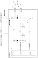
図1〜図4は、本発明の電磁アクチュエータ検査装置及び画像形成装置の一実施例を示す図であり、図1は、本発明の電磁アクチュエータ検査装置及び画像形成装置の一実施例を適用した画像形成装置1の制御基板10及び電磁アクチュエータ20の要部回路構成図である。
1 to 4 are diagrams showing an embodiment of an electromagnetic actuator inspection apparatus and an image forming apparatus according to the present invention, and FIG. 1 is an application example of the electromagnetic actuator inspection apparatus and the image forming apparatus according to the present invention. 2 is a circuit configuration diagram of a main part of a control board 10 and an
図1において、画像形成装置1は、複写装置、プリンタ装置、複合装置等の電子写真方式またはインク噴射方式等の画像形成方式で用紙、フィルム等の被画像形成媒体(以下、単に、用紙という。)に画像を形成する。画像形成装置1は、この画像形成において、給紙動作、作像動作等を行うのに、電磁アクチュエータ20が用いられており、制御基板10の制御下で、電磁アクチュエータ20のソレノイド(駆動コイル)21をPWM駆動して、電磁アクチュエータ20の図示しない可動鉄心を稼働させて、電磁アクチュエータ20に割り当てられている動作を行わせる。
In FIG. 1, an image forming apparatus 1 is an image forming medium such as a sheet or a film (hereinafter, simply referred to as a sheet) in an image forming system such as an electrophotographic system or an ink jet system such as a copying apparatus, a printer apparatus, or a composite apparatus. ). The image forming apparatus 1 uses an
制御基板10は、画像形成装置1の全体の制御を行うとともに、電磁アクチュエータ20の駆動制御及びアクチュエータ20の接続・断線検査を行うCPU11、抵抗R1、ダイオードD1、フィルタFt、ダイオードD2、トランジスタTr1及び抵抗R2等を搭載しており、端子Ta、Tbに電磁アクチュエータ20のソレノイド21が接続されている。
The control board 10 controls the entire image forming apparatus 1 and also controls the drive of the
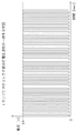
CPU(PWM駆動制御手段、判定手段)11は、その出力端子が、抵抗R2を介してトランジスタTr1のベースに接続されており、トランジスタTr1は、そのエミッタが接地されている。抵抗R2は、波形整形用の抵抗であり、立上り時のオーバーシュート波形や立下り時のアンダーシュート波形の発生を防止している。トランジスタ(駆動手段)Tr1は、そのコレクタに、ダイオードD2を挟んで、端子Ta、Tbを介して電磁アクチュエータ20のソレノイド(駆動コイル)21が接続されているとともに、24Vが印加されている。CPU11は、抵抗R2を介してトランジスタTr1のベースに、PWM制御信号を出力し、トランジスタTr1は、ベースにPWM制御信号が入力されると、該PWM制御信号に応じて、オン/オフ動作して、トランジスタTr1の接地端子であるエミッタとコレクタとの間、すなわち、GND−コレクタ間に、図2に示すような0Vと24Vとの間で周期的に変化するパルス状のPWM駆動信号を発生させ、このPWM駆動信号を、端子Ta、Tbを介して電磁アクチュエータ20のソレノイド21に供給する。
The output terminal of the CPU (PWM drive control means, determination means) 11 is connected to the base of the transistor Tr1 via the resistor R2, and the emitter of the transistor Tr1 is grounded. The resistor R2 is a waveform shaping resistor, and prevents the occurrence of an overshoot waveform at the rising edge or an undershoot waveform at the falling edge. The transistor (driving means) Tr1 is connected at its collector to the solenoid (driving coil) 21 of the
トランジスタTr1のコレクタに接続されているダイオードD2は、回生電流用のダイオードであり、電磁アクチュエータ20をPWM駆動させた場合におけるオフタイミング時の逆起電圧の発生を防止する。
The diode D2 connected to the collector of the transistor Tr1 is a diode for regenerative current, and prevents the generation of a counter electromotive voltage at the off timing when the
フィルタFtは、2つの抵抗R3、R4と2つのコンデンサC1、C2を備えた2段の積分回路であり、電磁アクチュエータ20をPWM駆動させた場合に、PWM制御周期で変動するトランジスタTr1のコレクタ部分の電圧を定電圧に変換して、電磁アクチュエータ20の接続・断線検出信号として生成する。
The filter Ft is a two-stage integrating circuit including two resistors R3 and R4 and two capacitors C1 and C2, and when the
ダイオードD1は、電圧クランプ用のダイオードであり、5V電源に接続されている。ダイオードD1は、フィルタFtによって生成された電磁アクチュエータ20の接続・断線検出信号を5V電源でクランプして、CPU11の入力端子に過電圧が印加されることを防止している。
The diode D1 is a voltage clamping diode and is connected to a 5V power source. The diode D1 clamps the connection / disconnection detection signal of the
抵抗R1は、論理固定用の抵抗であり、電磁アクチュエータ20が未接続であったり、断線している場合に、CPU11の入力端子の論理が不定になることを防止している。
The resistor R1 is a resistor for fixing logic, and prevents the logic of the input terminal of the CPU 11 from becoming indefinite when the
上記フィルタFt、ダイオードD1、抵抗R1は、全体として、電磁アクチュエータ20のPWM駆動におけるオフのタイミングにおいて、該電磁アクチュエータ20のソレノイド(駆動コイル)21に発生する電圧を検出する電圧検出部(電圧検出手段)30として機能している。
The filter Ft, the diode D1, and the resistor R1 as a whole are a voltage detection unit (voltage detection unit) that detects a voltage generated in the solenoid (drive coil) 21 of the
そして、トランジスタTr1によってPWM制御される電磁アクチュエータ20のソレノイド21に供給される駆動電圧のオンデューティ(Duty)と、フィルタFtで変換される定電圧の電圧値Vcontは、電磁アクチュエータ20の駆動電源を、Vcc(本実施例では、DC24V)、PWM制御のオンデューティを、D[%]としたとき、次式(1)で示す関係にある。
The on-duty (Duty) of the drive voltage supplied to the solenoid 21 of the
Vcnt=Vcc×(100−D)/100・・・(1)
次に、本実施例の作用について説明する。本実施例の画像形成装置1は、電磁アクチュエータ20をPWM制御駆動中に、電磁アクチュエータ20の接続・断線検出処理を行って、電磁アクチュエータ20が接続されているか否か、また、電磁アクチュエータ20のソレノイド21が断線しているか否かを安価にかつ高精度に検出する。
Vcnt = Vcc × (100−D) / 100 (1)
Next, the operation of this embodiment will be described. The image forming apparatus 1 according to the present embodiment performs connection / disconnection detection processing of the
本実施例の画像形成装置1は、画像処理装置1全体を制御するCPU11を搭載する制御基板10に、電磁アクチュエータ20のソレノイド21が接続されており、該制御基板10に搭載されているトランジスタTr1のベースに、CPU11の出力端子からPWM制御信号を出力して、トランジスタTr1を所定のオンデューティでオン/オフ動作させる。トランジスタTr1がオン/オフ動作することで、ダイオードD2を挟んだ端子Taと端子Tbに接続されている電磁アクチュエータ20のソレノイド21に該オンデューティでPWM制御されたPWM駆動電圧が印加され、電磁アクチュエータ20が駆動制御される。
In the image forming apparatus 1 of the present embodiment, a solenoid 21 of an
このときのトランジスタTr1のコレクタ部分の電圧波形は、上記図2のように示すことができ、PWM制御周期で、オン/オフを繰り返す。 The voltage waveform of the collector portion of the transistor Tr1 at this time can be shown as shown in FIG. 2, and is repeatedly turned on / off in the PWM control cycle.
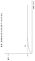
フィルタFtは、このときの電磁アクチュエータ20のソレノイド21の端子Tbの電圧、すなわち、トランジスタTr1のコレクタ部分の電圧を、定電圧に変換し、ダイオードD1で5V電源にクランプして接続・断線検出信号として、CPU11の入力端子に入力する。この接続・断線検出信号Saは、図3のように示すことができ、本実施例の画像形成装置1では、PWM制御のオンデューティ(Duty)が50%に設定されていて、上記式(1)によって、フィルタFtによって12Vの定電圧に変換されるが、ダイオードD1によって、さらに5V近傍にクランプされるため、5V程度での定電圧に飽和する。
The filter Ft converts the voltage at the terminal Tb of the solenoid 21 of the
そして、CPU11は、入力端子に入力される接続・断線検出信号の電圧に基づいて、電磁アクチュエータ20の接続・断線検出を行う。すなわち、電磁アクチュエータ20が接続され、断線もしていない場合には、CPU11の入力端子には5V程度の電圧が入力されるが、電磁アクチュエータ20が未接続、または、断線している場合には、CPU11の入力端子には、論理固定用の抵抗R1により接地レベル(GNDレベル)の電圧が入力されることになる。CPU11は、この入力電圧の電圧差を、High/Lowの論理で認識して、電磁アクチュエータ20が接続されているか、また、ソレノイド21が断線しているか否かの検出を行う。CPU11は、入力電圧がHighのときには、電磁アクチュエータ20が接続されていて、断線もしていない状態であると判断し、入力電圧がLowのときには、電磁アクチュエータ20が未接続、または、電磁アクチュエータ20のソレノイド21が断線している状態であると判断する。
Then, the CPU 11 detects the connection / disconnection of the
すなわち、CPU11は、図4に示すように、入力端子の入力電圧の論理がHighであるかチェックし(ステップS101)、入力電圧の論理がHighであると、電磁アクチュエータ20が接続されており、かつ、ソレノイド21が断線していない状態であると判定する(ステップS102)。
That is, as shown in FIG. 4, the CPU 11 checks whether the logic of the input voltage at the input terminal is High (step S101). If the logic of the input voltage is High, the
ステップS101で、入力電圧の論理がLowであると、CPU11は、電磁アクチュエータ20が接続されていないか、または、電磁アクチュエータ20のソレノイド21が断線していると判定する(ステップS103)。
If the logic of the input voltage is Low in step S101, the CPU 11 determines that the
そして、上記実施例において、CPU11の入力端子の入力電圧がHigh論理であると判断する閾値電圧Visの最小値を、2Vとした場合、上記(1)式及びダイオードD1による電圧クランプにより、PWM制御のオンデューティが0%(=入力電圧が5V)〜91.6%(=入力電圧が2.016V)の範囲において、電磁アクチュエータ20の接続・断線の検出を行うことができる。
In the above embodiment, when the minimum value of the threshold voltage Vis for determining that the input voltage of the input terminal of the CPU 11 is High logic is 2 V, the PWM control is performed by the above equation (1) and the voltage clamp by the diode D1. In the range of 0% (= input voltage is 5V) to 91.6% (= input voltage is 2.016V), the connection / disconnection of the
このように、PWM制御のオンデューティが0%のときであっても、電磁アクチュエータ20の接続・断線の検出を行うことができるため、電磁アクチュエータ20を駆動させていないときにも、電磁アクチュエータ20の接続・断線の検出を行うことができる。
Thus, even when the on-duty of the PWM control is 0%, the connection / disconnection of the
このように、本実施例の画像形成装置1は、CPU11の制御下で、トランジスタTr1が、電磁アクチュエータ20のソレノイド(駆動コイル)21への入力電力をPWM制御して、該電磁アクチュエータ20をPWM駆動するとともに、該電磁アクチュエータ20のPWM駆動におけるオフのタイミングにおいて、フィルタFt、ダイオードD1及び抵抗R1からなる電圧検出部30によって、電磁アクチュエータ20のソレノイド21に発生する電圧を検出してCPU11の入力端子に入力し、CPU11が、該検出電圧に基づいて電磁アクチュエータ20の接続の有無及びソレノイド21の断線の有無を判定している。
As described above, in the image forming apparatus 1 according to the present embodiment, the transistor Tr1 performs PWM control on the input power to the solenoid (drive coil) 21 of the
したがって、PWM制御駆動のオフのタイミングで、電磁アクチュエータ20のソレノイド21の電圧を検出することで、電磁アクチュエータ20の接続の有無及びソレノイド21の断線の有無を検出しているので、従来のような検出抵抗やコンパレータを用いることなく、電磁アクチュエータ20の接続の有無及びソレノイド21の断線の有無を高精度にかつ安価に検出することができる。
Accordingly, by detecting the voltage of the solenoid 21 of the
また、本実施例の画像形成装置1は、CPU11からトランジスタTr1のベースへPWM信号を出力して、トランジスタTr1をオン/オフ動作させて、電磁アクチュエータ20をPWM駆動させ、電圧検出部30が、トランジスタTr1と電磁アクチュエータ20のソレノイド21との接続点電圧を検出している。
Further, the image forming apparatus 1 according to the present embodiment outputs a PWM signal from the CPU 11 to the base of the transistor Tr1 to turn on / off the transistor Tr1 to drive the
したがって、より一層安価かつ高精度に電磁アクチュエータ20の接続の有無及びソレノイド21の断線の有無を検出することができる。
Therefore, the presence / absence of the connection of the
さらに、本実施例の画像形成装置1は、電圧検出部30が、トランジスタTr1と電磁アクチュエータ20のソレノイド21との接続点電圧を積分した積分電圧を検出している。
Further, in the image forming apparatus 1 of the present embodiment, the voltage detection unit 30 detects an integrated voltage obtained by integrating the connection point voltage between the transistor Tr1 and the solenoid 21 of the
したがって、電磁ソレノイド20のPWM駆動のオン/オフのタイミングに関わらず、電磁アクチュエータ20の接続の有無及びソレノイド21の断線の有無を高精度にかつ安価に検出することができる。
Therefore, it is possible to detect the presence / absence of connection of the
また、本実施例の画像形成装置1は、電圧検出ぶ30が、トランジスタTr1と電磁アクチュエータ20のソレノイド21との接続点電圧をダイオードD1でクランプした状態で検出している。
Further, in the image forming apparatus 1 of the present embodiment, the voltage detection unit 30 detects the connection point voltage between the transistor Tr1 and the solenoid 21 of the
したがって、広範囲のPWM駆動のオン/オフデューティにおいて、電磁アクチュエータ20の接続の有無及びソレノイド21の断線の有無を高精度にかつ安価に検出することができる。
Therefore, the presence / absence of connection of the
以上、本発明者によってなされた発明を好適な実施例に基づき具体的に説明したが、本発明は上記実施例で説明したものに限定されるものではなく、その要旨を逸脱しない範囲で種々変更可能であることはいうまでもない。 The invention made by the present inventor has been specifically described based on the preferred embodiments. However, the present invention is not limited to that described in the above embodiments, and various modifications can be made without departing from the scope of the invention. It goes without saying that it is possible.
本発明は、電磁アクチュエータを用いて可動部分を稼働させて画像形成する画像形成装置に利用することができる。 The present invention can be used in an image forming apparatus that forms an image by operating a movable part using an electromagnetic actuator.
1 画像形成装置
10 制御基板
11 CPU
R1 抵抗
D1 ダイオード
Ft フィルタ
D2 ダイオード
Tr1 トランジスタ
R2 抵抗
Ta、Tb 端子
R3、R4 抵抗
C1、C2 コンデンサ
20 電磁アクチュエータ
21 ソレノイド
DESCRIPTION OF SYMBOLS 1 Image forming apparatus 10 Control board 11 CPU
R1 Resistor D1 Diode Ft Filter D2 Diode Tr1 Transistor R2 Resistor Ta, Tb Terminal R3, R4 Resistor C1,
Claims (5)
前記駆動手段にPWM信号を出力して前記電磁アクチュエータをPWM駆動させるPWM駆動制御手段と、
前記電磁アクチュエータのPWM駆動におけるオフのタイミングにおいて、該電磁アクチュエータの前記駆動コイルに発生する電圧を検出する電圧検出手段と、
前記電圧検出手段の検出した電圧に基づいて、前記電磁アクチュエータの前記駆動手段への接続の有無と前記駆動コイルの断線の有無のうち少なくともいずれか一方を判定する判定手段と、
を備えていることを特徴とする電磁アクチュエータ検査装置。 PWM control of input power to the drive coil of the electromagnetic actuator, and drive means for PWM driving the electromagnetic actuator;
PWM drive control means for outputting a PWM signal to the drive means to PWM drive the electromagnetic actuator;
Voltage detection means for detecting a voltage generated in the drive coil of the electromagnetic actuator at an OFF timing in PWM driving of the electromagnetic actuator;
Determination means for determining at least one of the presence or absence of connection of the electromagnetic actuator to the drive means and the presence or absence of disconnection of the drive coil based on the voltage detected by the voltage detection means;
An electromagnetic actuator inspection device comprising:
前記PWM駆動制御手段は、前記トランジスタのベースに前記PWM信号を出力して該トランジスタをオン/オフ動作させて前記電磁アクチュエータをPWM駆動させ、
前記電圧検出手段は、前記トランジスタと前記電磁アクチュエータの前記駆動コイルとの接続点電圧を検出することを特徴とする請求項1記載の電磁アクチュエータ検査装置。 The drive means is a transistor connected to the drive coil of the electromagnetic actuator;
The PWM drive control means outputs the PWM signal to the base of the transistor to turn on / off the transistor to drive the electromagnetic actuator in PWM,
The electromagnetic actuator inspection apparatus according to claim 1, wherein the voltage detecting unit detects a connection point voltage between the transistor and the drive coil of the electromagnetic actuator.
前記電磁アクチュエータ検査部として、請求項1から請求項4のいずれかに記載の電磁アクチュエータ検査装置を搭載していることを特徴とする画像形成装置。 In an image forming apparatus equipped with an electromagnetic actuator inspection unit that detects the presence or absence of disconnection and disconnection of the electromagnetic actuator while forming an image by operating the movable part with an electromagnetic actuator.
An image forming apparatus comprising the electromagnetic actuator inspection device according to claim 1 as the electromagnetic actuator inspection portion.
Priority Applications (4)
| Application Number | Priority Date | Filing Date | Title |
|---|---|---|---|
| JP2010151329A JP2012014009A (en) | 2010-07-01 | 2010-07-01 | Electromagnetic actuator inspection device and image forming apparatus |
| US13/108,241 US20120001652A1 (en) | 2010-07-01 | 2011-05-16 | Electromagnetic actuator inspection device and image forming apparatus |
| EP11166819.0A EP2408251B1 (en) | 2010-07-01 | 2011-05-20 | Wireless access system |
| CN2011101856580A CN102313855A (en) | 2010-07-01 | 2011-07-01 | Electromagnetic actuator inspection device and image forming apparatus |
Applications Claiming Priority (1)
| Application Number | Priority Date | Filing Date | Title |
|---|---|---|---|
| JP2010151329A JP2012014009A (en) | 2010-07-01 | 2010-07-01 | Electromagnetic actuator inspection device and image forming apparatus |
Publications (1)
| Publication Number | Publication Date |
|---|---|
| JP2012014009A true JP2012014009A (en) | 2012-01-19 |
Family
ID=44645456
Family Applications (1)
| Application Number | Title | Priority Date | Filing Date |
|---|---|---|---|
| JP2010151329A Pending JP2012014009A (en) | 2010-07-01 | 2010-07-01 | Electromagnetic actuator inspection device and image forming apparatus |
Country Status (4)
| Country | Link |
|---|---|
| US (1) | US20120001652A1 (en) |
| EP (1) | EP2408251B1 (en) |
| JP (1) | JP2012014009A (en) |
| CN (1) | CN102313855A (en) |
Cited By (2)
| Publication number | Priority date | Publication date | Assignee | Title |
|---|---|---|---|---|
| JP2014211469A (en) * | 2013-04-17 | 2014-11-13 | キヤノン株式会社 | Fixation device |
| JP2020187238A (en) * | 2019-05-13 | 2020-11-19 | 株式会社リコー | Electromagnetic actuator driving circuit, electromagnetic actuator driving method, and image forming apparatus |
Families Citing this family (2)
| Publication number | Priority date | Publication date | Assignee | Title |
|---|---|---|---|---|
| FR2973155B1 (en) * | 2011-03-22 | 2017-02-10 | Schneider Electric Ind Sas | METHOD AND DEVICE FOR DIAGNOSING AN ACTUATOR, AND ACTUATOR COMPRISING SUCH A DEVICE |
| DE102013212277A1 (en) * | 2013-06-26 | 2014-12-31 | Continental Teves Ag & Co. Ohg | Method and circuit arrangement for detecting a tear or defect of a recirculation diode of an electrohydraulic valve |
Citations (14)
| Publication number | Priority date | Publication date | Assignee | Title |
|---|---|---|---|---|
| JPH04181268A (en) * | 1990-11-16 | 1992-06-29 | Ricoh Co Ltd | Electrophotographic image forming device |
| JPH04181267A (en) * | 1990-11-16 | 1992-06-29 | Ricoh Co Ltd | Electrophotographic image forming device |
| JPH0611531A (en) * | 1992-06-29 | 1994-01-21 | Casio Electron Mfg Co Ltd | Controller of electromagnetic equipment |
| JPH0736320A (en) * | 1993-07-21 | 1995-02-07 | Ricoh Co Ltd | Load abnormality detecting device |
| JPH08123591A (en) * | 1994-10-26 | 1996-05-17 | Mitsubishi Electric Corp | Multiplex bus circuit |
| JPH09211051A (en) * | 1996-01-30 | 1997-08-15 | Nec Home Electron Ltd | Disconnection-diagnosing apparatus |
| JPH10161251A (en) * | 1996-11-27 | 1998-06-19 | Canon Inc | Image forming device |
| JP2001228056A (en) * | 2000-02-15 | 2001-08-24 | Canon Inc | System and method for self-diagnosis and storage medium |
| JP2003307888A (en) * | 2002-04-16 | 2003-10-31 | Canon Inc | Image formation device |
| JP2004280069A (en) * | 2003-02-26 | 2004-10-07 | Canon Inc | Image forming apparatus |
| JP2004310665A (en) * | 2003-04-10 | 2004-11-04 | Nec Corp | Instantaneous outage control system and electronic apparatus using instantaneous outage control system |
| JP2004333795A (en) * | 2003-05-07 | 2004-11-25 | Canon Inc | Image forming apparatus |
| JP2005223168A (en) * | 2004-02-06 | 2005-08-18 | Mitsubishi Electric Corp | Electromagnetic actuator and its control method |
| JP2005268957A (en) * | 2004-03-16 | 2005-09-29 | Murata Mach Ltd | Connection detection circuit |
Family Cites Families (17)
| Publication number | Priority date | Publication date | Assignee | Title |
|---|---|---|---|---|
| US5481187A (en) * | 1991-11-29 | 1996-01-02 | Caterpillar Inc. | Method and apparatus for determining the position of an armature in an electromagnetic actuator |
| GB2280762A (en) * | 1993-07-31 | 1995-02-08 | Lucas Ind Plc | Testing and speed control of ABS pump motors |
| DE19628255C2 (en) * | 1996-07-12 | 1998-05-28 | Siemens Ag | Filter circuit |
| AUPO804797A0 (en) * | 1997-07-15 | 1997-08-07 | Silverbrook Research Pty Ltd | Image creation method and apparatus (IJ05) |
| US6652052B2 (en) * | 1997-07-15 | 2003-11-25 | Silverbrook Research Pty Ltd | Processing of images for high volume pagewidth printing |
| JP3926669B2 (en) * | 2002-04-24 | 2007-06-06 | 株式会社リコー | Wireless communication system and wireless access method |
| US8208364B2 (en) * | 2002-10-25 | 2012-06-26 | Qualcomm Incorporated | MIMO system with multiple spatial multiplexing modes |
| US6873190B2 (en) * | 2003-03-18 | 2005-03-29 | Hewlett-Packard Development Company, L.P. | Apparatus for sensing the presence of an inductive load driven by a pulse width modulated signal |
| CN2690895Y (en) * | 2003-12-26 | 2005-04-06 | 宝钢集团上海第一钢铁有限公司 | Line on-and-off detector |
| US20070294456A1 (en) * | 2006-06-16 | 2007-12-20 | Hong Kong Applied Science And Technology Research Institute Co., Ltd. | Data communication interface and communication devices incorporating same |
| KR20070121452A (en) * | 2006-06-22 | 2007-12-27 | 삼성전자주식회사 | Method and system for connecting between single wireless device and multiple host using wireless usb |
| JP5106013B2 (en) * | 2006-09-15 | 2012-12-26 | パナソニック株式会社 | Wireless communication apparatus and wireless communication method |
| US8674754B2 (en) * | 2007-02-09 | 2014-03-18 | Intel Mobile Communications GmbH | Loop filter and phase-locked loop |
| JP2009055413A (en) * | 2007-08-28 | 2009-03-12 | Ricoh Co Ltd | Radio communication apparatus |
| US7609069B2 (en) * | 2007-10-31 | 2009-10-27 | Kelsey-Hayes Company | Method to detect shorted solenoid coils |
| JP2010157591A (en) | 2008-12-26 | 2010-07-15 | Panasonic Corp | Semiconductor device, and method of manufacturing the same |
| CN101483407A (en) * | 2009-01-23 | 2009-07-15 | 上海日用-友捷汽车电气有限公司 | Novel motor load sampling circuit and application thereof |
-
2010
- 2010-07-01 JP JP2010151329A patent/JP2012014009A/en active Pending
-
2011
- 2011-05-16 US US13/108,241 patent/US20120001652A1/en not_active Abandoned
- 2011-05-20 EP EP11166819.0A patent/EP2408251B1/en active Active
- 2011-07-01 CN CN2011101856580A patent/CN102313855A/en active Pending
Patent Citations (14)
| Publication number | Priority date | Publication date | Assignee | Title |
|---|---|---|---|---|
| JPH04181268A (en) * | 1990-11-16 | 1992-06-29 | Ricoh Co Ltd | Electrophotographic image forming device |
| JPH04181267A (en) * | 1990-11-16 | 1992-06-29 | Ricoh Co Ltd | Electrophotographic image forming device |
| JPH0611531A (en) * | 1992-06-29 | 1994-01-21 | Casio Electron Mfg Co Ltd | Controller of electromagnetic equipment |
| JPH0736320A (en) * | 1993-07-21 | 1995-02-07 | Ricoh Co Ltd | Load abnormality detecting device |
| JPH08123591A (en) * | 1994-10-26 | 1996-05-17 | Mitsubishi Electric Corp | Multiplex bus circuit |
| JPH09211051A (en) * | 1996-01-30 | 1997-08-15 | Nec Home Electron Ltd | Disconnection-diagnosing apparatus |
| JPH10161251A (en) * | 1996-11-27 | 1998-06-19 | Canon Inc | Image forming device |
| JP2001228056A (en) * | 2000-02-15 | 2001-08-24 | Canon Inc | System and method for self-diagnosis and storage medium |
| JP2003307888A (en) * | 2002-04-16 | 2003-10-31 | Canon Inc | Image formation device |
| JP2004280069A (en) * | 2003-02-26 | 2004-10-07 | Canon Inc | Image forming apparatus |
| JP2004310665A (en) * | 2003-04-10 | 2004-11-04 | Nec Corp | Instantaneous outage control system and electronic apparatus using instantaneous outage control system |
| JP2004333795A (en) * | 2003-05-07 | 2004-11-25 | Canon Inc | Image forming apparatus |
| JP2005223168A (en) * | 2004-02-06 | 2005-08-18 | Mitsubishi Electric Corp | Electromagnetic actuator and its control method |
| JP2005268957A (en) * | 2004-03-16 | 2005-09-29 | Murata Mach Ltd | Connection detection circuit |
Cited By (3)
| Publication number | Priority date | Publication date | Assignee | Title |
|---|---|---|---|---|
| JP2014211469A (en) * | 2013-04-17 | 2014-11-13 | キヤノン株式会社 | Fixation device |
| JP2020187238A (en) * | 2019-05-13 | 2020-11-19 | 株式会社リコー | Electromagnetic actuator driving circuit, electromagnetic actuator driving method, and image forming apparatus |
| JP7354579B2 (en) | 2019-05-13 | 2023-10-03 | 株式会社リコー | Image forming device and electromagnetic actuator driving method |
Also Published As
| Publication number | Publication date |
|---|---|
| CN102313855A (en) | 2012-01-11 |
| US20120001652A1 (en) | 2012-01-05 |
| EP2408251A1 (en) | 2012-01-18 |
| EP2408251B1 (en) | 2019-12-04 |
Similar Documents
| Publication | Publication Date | Title |
|---|---|---|
| WO2011019038A1 (en) | Load drive control device and load drive control method | |
| US20140177284A1 (en) | Switching Power-Supply Apparatus | |
| JP2012014009A (en) | Electromagnetic actuator inspection device and image forming apparatus | |
| US10873282B2 (en) | Motor control apparatus for detecting stop position of rotor of motor and image forming apparatus | |
| CN102263511B (en) | Current resonance power supply and image forming device | |
| JP2009254179A (en) | Vehicle driving device | |
| JP4524663B2 (en) | Voltage control device for vehicle | |
| JP5988566B2 (en) | Power supply and image forming apparatus | |
| JP5099041B2 (en) | Fuel pump control device | |
| JP5582596B2 (en) | Printing apparatus and voltage control apparatus | |
| CN103034100A (en) | Power supply control apparatus, image forming apparatus, and power supply control method | |
| KR101503980B1 (en) | Driving apparatus for motor and motor driving method | |
| JP6160354B2 (en) | Power supply | |
| JP2004260980A (en) | Method for detecting abnormality in constant voltage stepping motor drive circuit | |
| JP2013041093A (en) | Image forming apparatus | |
| JP2008060461A (en) | Electromagnetic drive unit | |
| JP2011182066A (en) | Power supply device | |
| JP2006345683A (en) | Current detector | |
| JP2005198357A (en) | Inrush current preventing circuit | |
| JP2013021756A (en) | Power supply device | |
| CN105262354A (en) | Alternating-current power source detection device | |
| JP2006129543A (en) | Stepping motor driver and driving method | |
| US11476782B2 (en) | Image forming apparatus having motor, and motor control apparatus for controlling motor | |
| JP2009205299A (en) | Power unit, control method thereof and image forming apparatus | |
| JP4058431B2 (en) | Encoder disconnection detection method, encoder disconnection detection apparatus, and power conversion apparatus including the same |
Legal Events
| Date | Code | Title | Description |
|---|---|---|---|
| A621 | Written request for application examination |
Free format text: JAPANESE INTERMEDIATE CODE: A621 Effective date: 20130404 |
|
| RD02 | Notification of acceptance of power of attorney |
Free format text: JAPANESE INTERMEDIATE CODE: A7422 Effective date: 20130410 |
|
| A977 | Report on retrieval |
Free format text: JAPANESE INTERMEDIATE CODE: A971007 Effective date: 20131225 |
|
| A131 | Notification of reasons for refusal |
Free format text: JAPANESE INTERMEDIATE CODE: A131 Effective date: 20140107 |
|
| A521 | Request for written amendment filed |
Free format text: JAPANESE INTERMEDIATE CODE: A523 Effective date: 20140307 |
|
| A131 | Notification of reasons for refusal |
Free format text: JAPANESE INTERMEDIATE CODE: A131 Effective date: 20140826 |
|
| A02 | Decision of refusal |
Free format text: JAPANESE INTERMEDIATE CODE: A02 Effective date: 20150106 |