JP5106013B2 - Wireless communication apparatus and wireless communication method - Google Patents
Wireless communication apparatus and wireless communication method Download PDFInfo
- Publication number
- JP5106013B2 JP5106013B2 JP2007227910A JP2007227910A JP5106013B2 JP 5106013 B2 JP5106013 B2 JP 5106013B2 JP 2007227910 A JP2007227910 A JP 2007227910A JP 2007227910 A JP2007227910 A JP 2007227910A JP 5106013 B2 JP5106013 B2 JP 5106013B2
- Authority
- JP
- Japan
- Prior art keywords
- transmission
- reception
- wireless communication
- beacon
- sub
- Prior art date
- Legal status (The legal status is an assumption and is not a legal conclusion. Google has not performed a legal analysis and makes no representation as to the accuracy of the status listed.)
- Expired - Fee Related
Links
Images


Classifications
-
- H—ELECTRICITY
- H04—ELECTRIC COMMUNICATION TECHNIQUE
- H04B—TRANSMISSION
- H04B7/00—Radio transmission systems, i.e. using radiation field
- H04B7/02—Diversity systems; Multi-antenna system, i.e. transmission or reception using multiple antennas
- H04B7/04—Diversity systems; Multi-antenna system, i.e. transmission or reception using multiple antennas using two or more spaced independent antennas
- H04B7/08—Diversity systems; Multi-antenna system, i.e. transmission or reception using multiple antennas using two or more spaced independent antennas at the receiving station
- H04B7/0837—Diversity systems; Multi-antenna system, i.e. transmission or reception using multiple antennas using two or more spaced independent antennas at the receiving station using pre-detection combining
- H04B7/0842—Weighted combining
- H04B7/086—Weighted combining using weights depending on external parameters, e.g. direction of arrival [DOA], predetermined weights or beamforming
-
- H—ELECTRICITY
- H04—ELECTRIC COMMUNICATION TECHNIQUE
- H04B—TRANSMISSION
- H04B7/00—Radio transmission systems, i.e. using radiation field
- H04B7/02—Diversity systems; Multi-antenna system, i.e. transmission or reception using multiple antennas
- H04B7/04—Diversity systems; Multi-antenna system, i.e. transmission or reception using multiple antennas using two or more spaced independent antennas
- H04B7/06—Diversity systems; Multi-antenna system, i.e. transmission or reception using multiple antennas using two or more spaced independent antennas at the transmitting station
- H04B7/0613—Diversity systems; Multi-antenna system, i.e. transmission or reception using multiple antennas using two or more spaced independent antennas at the transmitting station using simultaneous transmission
- H04B7/0615—Diversity systems; Multi-antenna system, i.e. transmission or reception using multiple antennas using two or more spaced independent antennas at the transmitting station using simultaneous transmission of weighted versions of same signal
- H04B7/0617—Diversity systems; Multi-antenna system, i.e. transmission or reception using multiple antennas using two or more spaced independent antennas at the transmitting station using simultaneous transmission of weighted versions of same signal for beam forming
-
- H—ELECTRICITY
- H04—ELECTRIC COMMUNICATION TECHNIQUE
- H04W—WIRELESS COMMUNICATION NETWORKS
- H04W88/00—Devices specially adapted for wireless communication networks, e.g. terminals, base stations or access point devices
- H04W88/02—Terminal devices
Description
本発明は、無線通信装置および無線通信方法、特にモバイル環境下のアドホックネットワークにおける無線通信装置および無線通信方法に関する。 The present invention relates to a wireless communication device and a wireless communication method, and more particularly to a wireless communication device and a wireless communication method in an ad hoc network under a mobile environment.
PAN(Personal Area Network)は、近年発展しつつあるネットワーク技術である。特にマイクロ波UWB(Ultra Wide Band)を利用するWiMediaの仕様は、ECMA(European Computer Manufacturer Association)の規格として採用され、製品の出荷が間近となってきている。また、WiMediaの仕様は、ワイヤレスUSB(Universal Serial Bus)の規格に採用されているので、今後製品が広く市場に出回ることが期待されている。 PAN (Personal Area Network) is a network technology that has been developing in recent years. In particular, WiMedia specifications using microwave UWB (Ultra Wide Band) have been adopted as ECMA (European Computer Manufacturer Association) standards, and the shipment of products is approaching. In addition, since the specification of WiMedia is adopted in the standard of wireless USB (Universal Serial Bus), it is expected that the product will be widely marketed in the future.
WiMediaのMAC(Media Access Control)の技術の特徴としては、ビーコンピリオド方式が挙げられる。この方式は、互いに次近接範囲内に位置する自律分散デバイス(ノード)が送信するビーコンの位置が重ならないようにして、すべてのデバイスがビーコンの送信・交換を行い、すでに他のデバイスにより確保された予約スロットを侵害しないようにMAS(Media Access Slot)を予約宣言して通信を行う技術である。 A characteristic of WiMedia's MAC (Media Access Control) technology is a beacon period method. In this method, beacons sent by autonomous distributed devices (nodes) located within the next proximity range do not overlap, and all devices transmit and exchange beacons and are already secured by other devices. This is a technology for communicating by declaring a MAS (Media Access Slot) reservation so as not to infringe the reserved slot.
これに加え、最近、IEEE802.15.3Cなどの標準化委員会において、ミリ波帯でUWBを利用した技術が、マイクロ波帯よりは伝送距離は短いものの、マイクロ波帯よりはさらに高速化した無線技術として注目されつつある。この技術は、タッチアンドムーブ(Touch and Move)のように、駅の改札口などで、動画を含むファイルサイズの大きなデータを高速に受け渡せるようになることを目指して、検討が続けられている。 In addition to this, in recent years, standards such as IEEE802.15.3C have adopted a technology that uses UWB in the millimeter wave band, although the transmission distance is shorter than that in the microwave band, but the radio speed has been further increased compared to the microwave band. It is getting attention as a technology. This technology is being studied for the purpose of enabling high-speed data transfer, including video, at the ticket gates of stations, such as Touch and Move, at high speed. .
ミリ波の電波はマイクロ波とは異なり指向性をもつ。WiMediaのビーコンピリオド方式では、無指向性の電波を仮定しており、単純にMAC方式をWiMediaの方式をそのまま適用することはできない。その結果、IEEE802.15.3Cでは、位置が定まっている相手に対してアンテナを固定的に送信することを前提とした通信に限って検討を進めているのが現状である。 Unlike microwaves, millimeter-wave radio waves have directivity. The WiMedia beacon period method assumes omnidirectional radio waves and cannot simply apply the WiMedia method to the MAC method. As a result, IEEE802.15.3C is currently studying only communication that presupposes that the antenna is fixedly transmitted to the other party whose position is fixed.
また、特許文献1では、位置が定まっている基地局と加入者局との間で、セクタアンテナを用いてミリ波帯の1対多通信を行う技術が開示されている。
上記の従来技術では、位置が定まっていない、任意の位置のデバイス同士のマルチアクセスを実現することは困難である。もし上記のような現状を踏まえた上で、位置が定まっていない、任意の位置のデバイス同士のマルチアクセスを可能とするビーコンピリオド方式を実現しようとするならば、セクタアンテナという手段を活用することが考えられる。これは複数の指向性アンテナを2次元平面上の全方向に向くように張り合わせて、擬似的に無指向性のアンテナとする手段である。 In the above-described conventional technology, it is difficult to realize multi-access between devices at arbitrary positions whose positions are not fixed. If you want to realize a beacon period method that allows multi-access between devices at arbitrary positions, based on the current situation as described above, use a means called a sector antenna. Can be considered. This is a means of combining a plurality of directional antennas so as to be directed in all directions on a two-dimensional plane to form a pseudo omnidirectional antenna.
しかし、このように多数の指向性アンテナを同時に使用すると、他の通信装置に影響を与えるので、一度に送信することのできる全体の送信電力は制限される。その結果、一つのセクタアンテナからの送信出力は小さくせざるを得ない。このため、もともとミリ波の場合はあまり伝送距離が取れないところ、セクタアンテナを採用することによりさらに伝送距離が短くなってしまうという問題がある。 However, if a large number of directional antennas are used simultaneously in this way, it affects other communication devices, and thus the total transmission power that can be transmitted at one time is limited. As a result, the transmission output from one sector antenna must be reduced. For this reason, in the case of millimeter waves, the transmission distance is not so much, but there is a problem that the transmission distance is further shortened by adopting the sector antenna.
本発明は、かかる点に鑑みてなされたものであり、指向性の電波であっても、伝送距離を確保しつつ、ランダムマルチアクセスを実現することができる無線通信装置および無線通信方法を提供することを目的とする。 The present invention has been made in view of the above points, and provides a wireless communication apparatus and a wireless communication method capable of realizing random multi-access while ensuring a transmission distance even with a directional radio wave. For the purpose.
本発明の無線通信装置は、指向性電波を送受信して他の無線通信装置とアドホックネットワーク通信を行う無線通信装置であって、真逆の2方向において前記指向性電波の送受信を同時に行う送受信対を複数有するアンテナと、前記指向性電波の送受信を行う前記送受信対の切り替えを、タイミングを取って制御する制御部とを有し、前記制御部は、前記指向性電波の送受信を行う前記送受信対を規則的に切り替え、前記他の無線通信装置のキャリアを検出したタイミングおよび前記送受信対に基づいて、前記他の無線通信装置と同期する処理を行う構成を採る。 The wireless communication device of the present invention is a wireless communication device that transmits and receives directional radio waves and performs ad hoc network communication with other wireless communication devices, and transmits and receives the directional radio waves simultaneously in two opposite directions. an antenna having a plurality of the switching of the transceiver pair for transmitting and receiving the directional radio wave, have a control unit for controlling timed, the control unit, the transceiver pair for transmitting and receiving the directional wave Is switched regularly, and a process of performing processing to synchronize with the other wireless communication device is adopted based on the timing when the carrier of the other wireless communication device is detected and the transmission / reception pair .
本発明によれば、2次元または3次元空間のあらゆる端末とのランダムマルチアクセス通信を、指向性の電波であっても、伝送距離を確保しつつ実現することができる。 According to the present invention, random multi-access communication with any terminal in a two-dimensional or three-dimensional space can be realized while securing a transmission distance even with directional radio waves.
以下、本発明の各実施の形態について、図面を用いて詳細に説明する。 Hereinafter, embodiments of the present invention will be described in detail with reference to the drawings.
(実施の形態1)
図1は、本発明の実施の形態1に係る無線通信装置の構成を示すブロック図である。
(Embodiment 1)
FIG. 1 is a block diagram showing a configuration of a radio communication apparatus according to
図1に示す無線通信装置100は、セクタアンテナ110、キャリア検出部120、MAC部130、送受信部140および切替スイッチ150から構成されている。ここで、セクタアンテナ110を構成する指向性を持つ個々のアンテナ素子をセクタと呼び、例えばセクタ1とセクタ1の真反対の方向を向く(正反対の指向性を持つ)セクタ4とのペアを送受信対1−4と表記することにする。送受信対1−4、2−5、3−6は、それぞれセクタ1およびセクタ4、セクタ2およびセクタ5、セクタ3及びセクタ6から構成されている。また、MAC部130は、制御部132、ビーコン処理部134およびフレーム処理部136から構成されている。
A
なお、ここで、セクタの方向とは、アンテナ素子におけるアンテナゲインが最大となる方向をいう。本発明では、この方向は、電波到達可能範囲の中心線の方向に一致するようなものを使用するものとする。 Here, the direction of the sector means a direction in which the antenna gain in the antenna element is maximized. In the present invention, this direction is assumed to coincide with the direction of the center line of the radio wave reachable range.
本実施の形態の無線通信装置100は、上記の構成により、指向性の電波であっても、伝送距離を確保しつつ、ランダムマルチアクセスを実現することができる。
With the above configuration,
本実施の形態では、スーパーフレームを用いたビーコンピリオド方式をとる。自律分散ネットワーク上にて、スーパーフレーム同期を取るために、無線ネットワークに参加する全デバイスがビーコンを整列させて送信することにより、互いのデバイスを認識していることを確認する。このとき、第Xスロットには、デバイスAのビーコンが存在する、というような情報を複数のデバイスが送信し合う。ここで、あるデバイスが他のデバイスのビーコンを受信した場合、受信したビーコンのうち一つでも自己の送信するスロットに自己のアドレスが書かれているか否かを判定する。判定を行った結果、自己のアドレスが書かれていないと認識すると、そのデバイスは重複(衝突)が発生しているものと判断して別のスロットに移動することとなる。結果的にそのデバイスは、近接または次近接のデバイスのアドレスの一覧を取得することができ、自己のビーコンを送信するスロットを決定するのに役立てることができる。 In this embodiment, a beacon period method using a superframe is adopted. In order to achieve superframe synchronization on the autonomous distributed network, it is confirmed that all devices participating in the wireless network recognize each other's devices by aligning and transmitting beacons. At this time, a plurality of devices transmit information such that the beacon of device A exists in the Xth slot. Here, when a certain device receives a beacon of another device, it is determined whether at least one of the received beacons has its own address written in a slot transmitted by itself. As a result of the determination, if it is recognized that its own address is not written, the device determines that duplication (collision) has occurred and moves to another slot. As a result, the device can obtain a list of addresses of neighboring or next-neighboring devices, which can help determine the slot to transmit its beacon.
セクタアンテナ110は、全平面方向に送受信可能になるように2N個のセクタ(Nは2以上の整数)が配置されて構成されている。そして、セクタアンテナ110に対応付けてスーパーフレームをN個のサブスーパーフレームに等分割して、各サブスーパーフレームをN個の各送受信対と対応づける。送受信部140は、各サブスーパーフレームの期間中に対応づけられた送受信対からそのサブスーパーフレームの送受信を行う。サブスーパーフレームの送受信が終わると、送受信対は、切り替えられ、必要に応じて次のサブスーパーフレームの送受信をそのサブスーパーフレームに対応づけられた送受信対が行う。本実施の形態では、N=3の場合について記載している。
The
次に、図2を参照して、本実施の形態に係るセクタアンテナ110の構成を説明する。本実施の形態においては、全体を3対の送受信対1−4、2−5、3−6に分割して構成し、6つのセクタ1、2、3、4、5および6を2次元平面に配置する。すなわち、送受信対1−4は、セクタ1とセクタ4、送受信対2−5は、セクタ2とセクタ5、送受信対3−6は、セクタ3とセクタ6からそれぞれ構成されている。
Next, the configuration of the
また、セクタアンテナ110の周囲のエリアは、エリア201、202、203、204、205および206の6つのエリアに分けて考える。セクタ1のアンテナは、エリア201の方向に指向性を有し、エリア201に存在するデバイスとデータを送受信することができる。同様に、セクタ2、3、4、5、6のアンテナは、それぞれエリア202、203、204、205に存在するデバイスと送受信することができる。
Further, the area around the
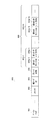
次に、図3を参照して本実施の形態のスーパーフレームの構成を説明する。スーパーフレーム300は、3つのサブスーパーフレームに等分割されている。すなわち、スーパーフレーム300は、左から順に1−4対のサブスーパーフレーム311、2−5対のサブスーパーフレーム312、および3−6対のサブスーパーフレーム313から構成されている。本実施の形態の無線通信装置(以下、デバイスという)は、近接、次近接にある全てのデバイスに対して、このスーパーフレームによりデータの送受信を行う。尚、サブスーパーフレームは、複数の送受信対に対応して定められており、スーパーフレームを構成する複数のサブスーパーフレームのうちの一つである。 Next, the configuration of the super frame according to the present embodiment will be described with reference to FIG. Superframe 300 is equally divided into three sub-superframes. That is, the super frame 300 is configured by 1-4 pairs of sub super frames 311, 2-5 pairs of sub super frames 312 and 3-6 pairs of sub super frames 313 in order from the left. The wireless communication apparatus (hereinafter referred to as a device) according to the present embodiment transmits / receives data to / from all devices in proximity and next proximity using this superframe. The sub-superframe is defined corresponding to a plurality of transmission / reception pairs, and is one of a plurality of sub-superframes constituting the superframe.
1−4対のサブスーパーフレーム311は、先頭に位置する1−4対のビーコンピリオド321(BP:Beacon Period)と1−4対のデータピリオド(DP:Data Period)331から構成されている。1−4対のビーコンピリオド321の先頭が1−4対のサブビーコンピリオド開始時間となっている。2−5対のサブスーパーフレーム312、3−6対のサブスーパーフレーム313も同様に理解することができる。尚、スーパーフレーム300の開始は、1−4対のサブビーコンピリオド開始時間と考えてもよいが、2−5対のサブビーコンピリオド開始時間または3−6対のサブビーコンピリオド開始時間に開始すると考えてもよい。1−4対のビーコンピリオド321には、送受信対1−4により送受信する場合のビーコンが、1−4対のデータピリオド331には、送受信対1−4により送受信する場合のフレームがそれぞれ記載される。2−5対および3−6対のビーコンピリオド322,323、データピリオド332,333も同様である。
The 1-4 pairs of sub-superframes 311 are composed of 1-4 pairs of beacon periods 321 (BP: Beacon Period) and 1-4 pairs of data periods (DP: Data Period) 331 located at the head. The beginning of the 1-4 pairs of
1−4対のサブスーパーフレーム311は、セクタ1とセクタ4の送受信対(アンテナ対)により送受信し、2−5対のサブスーパーフレーム312は、セクタ2とセクタ5の送受信対により送受信し、3−6対のサブスーパーフレーム313は、セクタ3とセクタ6の送受信対によりそれぞれ送受信する。
1-4 pairs of sub-superframes 311 are transmitted / received by a transmission / reception pair (antenna pair) of
次に、無線通信装置100の構成要素について、図1を参照して詳細に説明する。
Next, components of the
上記のように、セクタアンテナ110において、送受信対1−4は、セクタ1とセクタ4から構成され、セクタ1とセクタ4とは真反対の向きにあり、互いに180°の角度をなしている(図1および図2を参照)。同様に送受信対2−5は、セクタ2とセクタ5から構成され、セクタ2とセクタ5とは真反対の向きにあり、互いに180°の角度をなしているので、指向性も正反対となっている。また、送受信対3−6は、セクタ3とセクタ6から構成され、セクタ3とセクタ6とは真反対の向きにあり、互いに180°の角度をなしている。セクタ2の向きは、セクタ1に対して反時計回りに60°の方向にあり、セクタ3の向きはセクタ1に対して反時計回りに120°の方向にある。セクタ1は、角度0の方向を中心として±30°の方向からくる電波に対して指向性をもつアンテナとして機能し、その方向に存在する他のデバイスとの送受信が可能である。セクタ2以下も同様に理解することができる。
As described above, in the
キャリア検出部120は、セクタアンテナ110の送受信対1−4、2−5、3−6のそれぞれと接続されており、いずれかの送受信対で受信した電波を復調し、スーパーフレームの期間にビーコンを含む何らかの信号(キャリア)を検出した場合、その最初にキャリアを検出したタイミングと送受信対を示す情報をMAC部130の制御部132へ伝える。
The
MAC部130は、上位層からのデータフレームを送受信する役割の他に、キャリア検出部120からの情報(キャリアを検出したタイミングと送受信対)を受け取り、切替スイッチ150に対して同期情報を送るとともに、各サブスーパーフレームにおけるビーコンの解読、生成を行う役割を有している。
In addition to the role of transmitting and receiving data frames from higher layers, the
制御部132は、同期制御と切替スイッチ150の切替タイミング制御を行う。すなわち、制御部132は、キャリア検出部120からそのキャリアを検出したタイミングを受け取ると、そのタイミングをそのキャリアを検出した送受信対のサブスーパーフレームの先頭とみなして、そのタイミングを切替スイッチ150、ビーコン処理部134およびフレーム処理部136へ伝える。また、制御部132は、各サブスーパーフレームにおいて、サブスーパーフレームの先頭のタイミングを切替スイッチ150へ伝える。
The
ビーコン処理部134は、制御部132からサブスーパーフレームの先頭のタイミングを受け取ると、これを基準にして、そのサブスーパーフレームの自己のデバイスのビーコンを発信するタイミングを決定する。ビーコン処理部134は、そのタイミングに自己のデバイスのビーコンを送信できるようにビーコンを作成し、フレーム処理部136へ渡す。
When the
また、ビーコン処理部134は、フレーム処理部136から他のデバイスが発信したビーコンを読みとり、送受信対の直線上に存在する他のデバイスの存在を認識すると共に、これと重複しないビーコンスロット(ビーコンピリオド内のビーコンの位置)を自己のビーコンスロットとして決定し、そのスロットのタイミングでビーコンを生成し、フレーム処理部136へ渡す処理を行う。
Also, the
フレーム処理部136は、制御部132からサブスーパーフレームの先頭のタイミングを受け取ると、これを基準にして、そのサブスーパーフレームのデータピリオドを発信するタイミングを決定する。また、フレーム処理部136は、受信したデータに対しMACフレームを作成するために必要な処理を行い、上位層へ送信する。また、フレーム処理部136は、上位層から受け取った送信すべきデータに対してはMACフレームを物理層の信号に変換して送受信部140へ渡す。
When the
フレーム処理部136は、スーパーフレームを構成する複数のサブスーパーフレームの各サブスーパーフレームごとに、対応する送受信対を介してデータフレームを送受信する。さらに、フレーム処理部136は、現にデータフレームの送受信を行う送受信対に対応するサブスーパーフレーム以外のサブスーパーフレームにも、現にデータフレームの送受信を行う送受信対を介してデータフレームを送受信する。
The
送受信部140は、ビーコン処理部134からフレーム処理部136を介してビーコンを、フレーム処理部136からフレームデータを受け取り、サブスーパーフレームを構築して、物理層として必要な信号処理を行い、変調を行いキャリアに乗せて、切替スイッチ150へ渡す。また、送受信部140は、切替スイッチ150から受け取ったキャリアを復調して物理層の信号へ変換し、フレーム処理部136とフレーム処理部136を介してビーコン処理部134とへ渡す。
The transmission /
切替スイッチ150は、サブスーパーフレームの期間、そのサブスーパーフレームに対応する送受信対でのみ信号の送受ができるようにスイッチ動作を行う。例えば、1−4対のスーパーフレーム311の期間中、切替スイッチ150は、送受信対1−4、つまりセクタ1とセクタ4のみが送受信部と接続されるように切替の動作を行う。ビーコンピリオドの期間中は、サブスーパーフレームに対応する送受信対でのみ接続する。データピリオドの期間中は、原則としては、サブスーパーフレームに対応する送受信対でのみ接続するが、後述するようにサブスーパーフレームに対応する送受信対以外の送受信対からデータを受け取るようにしてもよい。
The
なお、本実施の形態においては、制御部132をMAC部130の一部として記述しているが、制御部132をMAC部の外に設けてもよいし、切替スイッチ150および送受信部140とともにPHY部の一部となる構成でもよい。
In the present embodiment, the
次に、本実施の形態におけるスーパーフレーム300の同期の動作について、図4を参照して説明する。 Next, the synchronization operation of superframe 300 in the present embodiment will be described with reference to FIG.
まず、3つの送受信対1−4、2−5、3−6に対して、キャリア検出部120は、他の通信装置から受信したスーパーフレーム300の期間にキャリアが出ているかどうかを一定期間監視する(S410)。もしキャリア検出部120がキャリアを検出した場合(S420:YES)、そのキャリアの検出タイミングは、キャリア検出した送受信対のサブスーパーフレームの先頭であり、サブビーコンピリオド開始時間のタイミングである。このサブビーコンピリオド開始時間に基づいてスーパーフレーム300の同期を行う。
First, for the three transmission / reception pairs 1-4, 2-5, and 3-6, the
選別したキャリアの検出タイミング、つまりサブビーコンピリオド開始時間に基づいて、そのキャリアを検出した送受信対を経由して受信したサブスーパーフレームにより、ビーコン処理部134は、実際にビーコンの受信を試行する(S430)。但し、試行してもビーコンを検出しないため試行を複数回繰り返す場合は、これまで試行したタイミングを除いたものからキャリア検出して再試行を行う。試行によりビーコン処理部134がビーコンを検出できなかったときは(S440:NO)、ステップ410に戻り、3つの送受信対それぞれにおいて、キャリア検出部120は、他のデバイスから受信したスーパーフレーム300の期間にキャリアが出ているかどうかを一定期間監視する。
Based on the detection timing of the selected carrier, that is, the sub-beacon period start time, the
もし、キャリア検出部120がビーコンを検出した場合は(S440:YES)、制御部132は、そのビーコンの値に従ってスーパーフレーム同期を実行する。具体的には、ビーコンを受信したときの時刻から、ビーコンのオフセットの時間を差し引いてビーコンピリオド開始時間を割り出す。ビーコンピリオド開始時間が分かれば、それに基づいて自装置が送受信するビーコンのタイミングも決定できる。
If the
制御部132は、このタイミングでビーコンを送信するようビーコン処理部134に指示する。ビーコン処理部134は、フレーム処理部136と送受信部140と切替スイッチ150を介してビーコンを送信する(S450)。尚、ステップ420において、キャリア検出部120が一定時間内にキャリアを検出しなかった場合(S420:NO)、近くにデバイスが存在していないと判断し、任意の時間でビーコンを送信する(S460)。このようにすれば、いつか他のデバイスが接近したときに通信を行うきっかけとすることができるからである。
The
尚、制御部132は、同じタイミングで複数の送受信対から信号を受信したなら、どれか一つの信号を選別する。先に受信した送受信対からの信号を優先的に選別してもよい。また、複数の送受信対からのサブスーパーフレームの中にタイミングが一致するものがあれば、そのような送受信対のサブスーパーフレームの開始時間を基準に他のサブスーパーフレームの同期を行い、スーパーフレーム300全体の同期を行う。
Note that if the
制御部132は、キャリア信号検出により決定したサブスーパーフレームの開始時間と、実際に受信したビーコンのサブビーコンピリオド開始時間とが、異なっている場合には、実際に受信したビーコンのサブビーコンピリオド開始時間に従ってスーパーフレーム同期を行う。
If the start time of the sub superframe determined by the carrier signal detection and the sub beacon period start time of the actually received beacon are different, the
サブビーコンピリオドにおけるビーコンの送出方法は、周知のWiMediaのビーコンピリオドにおけるビーコンの送出方法と基本的には同じである。異なる点は、サブビーコンピリオドは、1つのスーパーフレーム300に3回到来し、各サブビーコンピリオドにおいて1回ずつビーコンを送信するため、1つのスーパーフレーム毎に計3回ビーコンを送信することである。 The beacon transmission method in the sub-beacon period is basically the same as the beacon transmission method in the well-known WiMedia beacon period. The difference is that the sub-beacon period arrives three times in one superframe 300 and transmits a beacon once in each sub-beacon period, so that a beacon is transmitted a total of three times per superframe. .
各デバイスは、各サブビーコンピリオド内で自己のビーコン内にあるDRPIE(Distributed Reservation Protocol Information Element)に、そのサブスーパーフレームの中の通信を行うデータスロットの開始時刻を指定することができる。各デバイスは、ビーコンを送信しているデバイスが自己のほかにいないサブスーパーフレームがどのサブスーパーフレームであるかという情報を、そのサブスーパーフレームで送信するビーコンにおいて宣言し、通信の開始を要求することができる。 Each device can designate the start time of the data slot for communication in the sub-superframe in DRPIE (Distributed Reservation Protocol Information Element) in its own beacon within each sub-beacon period. Each device declares in the beacon transmitted in the sub-superframe the information on which sub-superframe the device that is transmitting the beacon is not other than itself, and requests the start of communication. be able to.
図5は、無線通信サブスーパーフレームを通知する「SSF Availability IE」(SSF:Sub SuperFrame、IE:Information Element)を示している。サブスーパーフレームが、ビーコンを送信しているデバイスが自己のほかに存在しないサブスーパーフレームの場合には、そのサブスーパーフレームに対応するビットフラグに0をたてる。また、サブスーパーフレームが、ビーコンを送信しているデバイスが自己のほかに存在するサブスーパーフレームの場合には、そのサブスーパーフレームに対応するビットフラグに1をたてる。「SSF Availability IE ID」には、SSF Availability IEのIDが記述される。固定部510には、デバイスアドレスなどが記述される。
FIG. 5 shows “SSF Availability IE” (SSF: Sub SuperFrame, IE: Information Element) for notifying the radio communication sub superframe. If the sub-superframe is a sub-superframe in which no other device is transmitting the beacon, 0 is set in the bit flag corresponding to the sub-superframe. If the sub-superframe is a sub-superframe in which the device transmitting the beacon exists other than itself, 1 is set to the bit flag corresponding to the sub-superframe. The “SSF Availability IE ID” describes the ID of the SSF Availability IE. The fixed
例えば、デバイスCが、2−5対サブスーパーフレーム312において他のデバイスAと通信していて、かつ、デバイスCが、1−4対のサブスーパーフレーム311と3−6対のサブスーパーフレーム313において他のデバイスのビーコンを検出しない場合は、1−4対のサブスーパーフレーム311のビットフラグ520は0となり、2−5対のサブスーパーフレーム312のビットフラグ530は1となり、3−6対のサブスーパーフレーム313のビットフラグ540は0となる。
For example, device C is communicating with other device A in 2-5 pair sub-superframe 312 and device C is 1-4 pairs of sub-superframes 311 and 3-6 pairs of sub-superframes 313. When the beacon of another device is not detected in FIG. 4, the
他のデバイスは、上記のビットフラグが立ったサブスーパーフレームにおいて、ビーコンを参照して、通信の開始を要求したデバイスが、他のデバイスにとって通信したい相手である場合は、DRP Requestを通信したい相手に対して送信する。DRP Requestを受けつけるときにはその旨のレスポンスを返す。すなわち、他のデバイスは、サブスーパーフレームの中の通信を行うデータスロットの開始時刻を指定してレスポンスを返送して予約を成立させ、その予約に従って通信を開始することができる。これは通信相手のいない送受信対のサブスーパーフレームの時間を有効に利用する方法である。 The other device refers to the beacon in the sub-superframe in which the above bit flag is set, and if the device that requested the start of communication is the other party that the other device wants to communicate with, the other party that wants to communicate the DRP Request Send to. When receiving a DRP Request, a response to that effect is returned. In other words, the other device can specify the start time of the data slot for communication in the sub-superframe, return a response, establish a reservation, and start communication according to the reservation. This is a method of effectively using the time of the sub superframe of a transmission / reception pair with no communication partner.
次に、図6を参照して、本実施の形態に係る複数のデバイスが互いに同期を取る場合のスーパーフレームの使用状況を説明する。まず、デバイスAは、デバイスBの送受信対3−6の延長線の近くにあり、デバイスBはデバイスAの送受信対3−6の延長線の近くにあるので、デバイスAとデバイスBは送受信対3−6にて同期する。その結果、デバイスAのフレーム処理部136は、ビーコンA3を送信し、ビーコンB1および受信データ601Aを受信する。デバイスBのフレーム処理部136は、ビーコンA4を受信し、ビーコンB4および送信データ601Bを送信する。送信データ601Bと受信データ601Aは、エラーがない限り同一である。
Next, with reference to FIG. 6, description will be given of a superframe usage situation when a plurality of devices according to the present embodiment synchronize with each other. First, since device A is near the extension line of transmission / reception pair 3-6 of device B and device B is near the extension line of transmission / reception pair 3-6 of device A, device A and device B are Synchronize at 3-6. As a result, the
その結果、デバイスAとデバイスBでは、3−6対のサブスーパーフレーム313の同期が行われるとともに、スーパーフレーム300の同期が行われることになる。 As a result, in device A and device B, the 3-6 pairs of sub superframes 313 are synchronized and the superframe 300 is synchronized.
ここで、デバイスがビーコンを送信するときに、どの送受信対のサブスーパーフレームであるかを相手に伝える必要はない。例えば、デバイスAがデバイスBと3−6対のサブスーパーフレーム313で同期を取った場合に、デバイスBが同期を取った送受信対が、例えば1−4対のサブスーパーフレーム311だと認識していたとしても、各デバイスが一定方向(左回りまたは右回り)にスーパーフレーム300を同じ速度で回転する限りにおいては、周囲から見た場合に同じ送受信対を回転しているように見え、位相差は一定であるので、同期が取れていると考えることができる。 Here, when the device transmits a beacon, it is not necessary to tell the other party which sub-superframe of which transmission / reception pair is being transmitted. For example, when device A synchronizes with device B in 3-6 pairs of sub-superframes 313, the transmission / reception pair with which device B has synchronized is recognized as, for example, 1-4 pairs of sub-superframes 311. As long as each device rotates the superframe 300 at a constant speed (counterclockwise or clockwise) at the same speed, it appears that the same transmission / reception pair is rotating when viewed from the surroundings. Since the phase difference is constant, it can be considered that synchronization is achieved.
次に、デバイスAとデバイスBが送受信対3−6で同期した状態で、デバイスAとデバイスCが同期しようとした場合を考える。デバイスAとデバイスCは、両者の送受信対2−5の延長線の近くに配置されているので、互いに2−5対のサブスーパーフレーム312で同期することができる。その結果、デバイスAのフレーム処理部136は、ビーコンA2および送信データ602Aを送信し、ビーコンC1を受信する。デバイスCのフレーム処理部136は、ビーコンA5および受信データ602Cを受信し、ビーコンC4を送信する。送信データ602Aと受信データ602Cは、エラーがない限り同一である。
Next, consider a case where device A and device C try to synchronize while device A and device B are synchronized in transmission / reception pair 3-6. Since device A and device C are arranged near the extension line of their transmission / reception pair 2-5, they can be synchronized with each other in 2-5 pairs of sub-superframes 312. As a result, the
このようにデバイスAとデバイスBの同期が取れ、デバイスAとデバイスCの同期が取れたとき、ここで送受信対1−4の延長線の近くに配置されているデバイスCとデバイスBは同じタイミングで、互いに送受信対1−4を向いているのでこの送受信対を使用した通信を行うことができる。1−4対のサブスーパーフレーム311でデバイスBとデバイスCが同期することも、同時に可能とすることができる。したがって、デバイスAとデバイスB、デバイスAとデバイスC、およびデバイスBとデバイスCの3組が同期することが同時に可能となる。これがこの方式の最大のメリットである。尚、図6には、デバイスBは、ビーコンB2を送信し、ビーコンC2を受信し、デバイスCはビーコンB5を受信し、ビーコンC3を送信している様子が示されている。 Thus, when the device A and the device B are synchronized and the device A and the device C are synchronized, the devices C and B arranged near the extension line of the transmission / reception pair 1-4 are at the same timing. Therefore, since the transmission / reception pair 1-4 faces each other, communication using the transmission / reception pair can be performed. The device B and the device C can be synchronized in the 1-4 pairs of sub-superframes 311 at the same time. Therefore, three sets of device A and device B, device A and device C, and device B and device C can be synchronized at the same time. This is the greatest merit of this method. FIG. 6 shows a state where device B transmits beacon B2 and receives beacon C2, and device C receives beacon B5 and transmits beacon C3.
このような同期をとることが可能な送受信対の切替方法としては、左回り、または右回りに隣の送受信対に移動させる方法がある。このほかに、送受信対をN個(Nは、2以上の自然数)としたときの左または右回りにM個ずつ飛ばして(Mは、自然数であるが、隣の送受信対に移動するときは0と解釈できる)切り替える(但しNとM+1は互いに素な自然数)ことが考えられる。例えば、M=2、N=4であれば、左回りにセクタの番号が1、2、3、…と付けられているとすると、セクタ1と5、セクタ4と8、セクタ7と3(セクタ3と7)、セクタ2と6の順で送受信対が移動し一巡する。
As a method of switching between the transmission / reception pair capable of such synchronization, there is a method of moving to the adjacent transmission / reception pair counterclockwise or clockwise. In addition to this, when the number of transmission / reception pairs is N (N is a natural number of 2 or more), M is skipped left or right (M is a natural number, but when moving to the next transmission / reception pair) (It can be interpreted as 0) switching (where N and M + 1 are relatively prime natural numbers). For example, if M = 2 and N = 4, assuming that the sector numbers are assigned counterclockwise 1, 2, 3,...,
次に、図7を参照して、空きサブスーパーフレームの活用方法について説明する。図7の上半分はデバイスAとデバイスBとが、3−6対のサブスーパーフレーム313のみを用いて送受信を行う様子を示している。デバイスBのフレーム処理部136は、ビーコンB14および送信データ701Bを送信し、ビーコンA14を受信する。デバイスAのフレーム処理部136は、ビーコンA13を送信し、ビーコンB11および受信データ701Aを受信する。デバイスAとデバイスBは、3−6対のサブスーパーフレーム313以外では、送受信する相手はいないため、単に自己のビーコンA11、A12、B12、B13を送信しているのみである。
Next, with reference to FIG. 7, a method for utilizing an empty sub superframe will be described. The upper half of FIG. 7 shows a state in which device A and device B perform transmission / reception using only 3-6 pairs of sub-superframes 313. The
そこで、空いている1−4対のサブスーパーフレーム311のビーコンピリオド321および2−5対のサブスーパーフレーム312のビーコンピリオド322のみそれぞれの送受信対で動作して、データピリオド331および332においては送受信対3−6でデータ交換を行う様子が図7の下半分に記述されている。ビーコンピリオドのみで本来のサブスーパーフレームに対応する送受信対で送受信しているのは、新規参加デバイスや移動により送受信可能になるデバイスに対して同期をとるために、それぞれのデバイスのビーコンは送信しておく必要があるためである。
Therefore, only the
より具体的には、1−4対のサブスーパーフレーム311および2−5対のサブスーパーフレーム312においては、デバイスAのフレーム処理部136は、それぞれビーコンA11およびA12を送信する。データピリオド331、332においてはデバイスAのフレーム処理部136が、送受信対3−6を用いて受信データ702A、703Aを受信する。また、デバイスBのフレーム処理部136は、1−4対のサブスーパーフレーム311および2−5対のサブスーパーフレーム312においては、それぞれビーコンB12およびB13を送信し、データピリオド331,332においてはデバイスBのフレーム処理部136が、送受信対3−6を用いて送信データ702B、703Bを送信する。3−6対のサブスーパーフレーム313においては、3−6対のサブスーパーフレーム313のみを用いて送受信を行う場合と同様である。
More specifically, in the 1-4 pairs of sub-superframes 311 and 2-5 pairs of sub-superframes 312, the
ここでは、フレーム処理部136は、現にデータフレームの送受信を行う送受信対に対応するサブスーパーフレーム以外のサブスーパーフレームにも、現に送受信を行う送受信対を介して前記データフレームを送受信する。
Here, the
このようにして、送受信対を切り替えていく際に生じる空きサブスーパーフレームを有効活用して、平面上の多数のデバイスとより多くのデータを送受信することができる。 In this way, it is possible to effectively transmit and receive more data with a large number of devices on a plane by effectively utilizing an empty sub-superframe that is generated when a transmission / reception pair is switched.
このように、本実施の形態に係る無線通信装置100は、それぞれ指向性が互いに正反対である2つの送受信方向からなる複数の送受信対を有し、複数の送受信対のそれぞれを単位として指向性電波を送受信するセクタアンテナ110と、複数の送受信対を時間的に切り替える切替スイッチ150と、を有しているため、端末とのランダムマルチアクセス通信を、指向性のある電波であっても、伝送距離を確保しつつ実現することができる。
Thus,
一方、単一の送受信セクタを回転させていく場合には、同じ向きで回転させた場合には、互いに向き合う方向にならず送受信ができないという問題が生じうる。しかし、本実施の形態に係る無線通信装置は、それぞれ指向性が互いに正反対である2つの送受信方向からなる複数の送受信対を有しているため、同じ向きで送受信対を回転させた場合にも、互いに向き合う方向に送受信対を配置することができるため、無線通信装置の送受信が可能となる。 On the other hand, when a single transmission / reception sector is rotated, there is a problem that transmission / reception cannot be performed when the rotation is performed in the same direction and the directions do not face each other. However, since the wireless communication apparatus according to the present embodiment has a plurality of transmission / reception pairs each having two transmission / reception directions whose directivities are opposite to each other, even when the transmission / reception pair is rotated in the same direction, Since the transmission / reception pair can be arranged in the direction facing each other, the wireless communication device can transmit and receive.
また、2次元または3次元空間のあらゆる端末とのランダムマルチアクセス通信を、指向性のある電波であっても、送信出力を小さくせず伝送距離を確保しつつ実現することができる。 In addition, random multi-access communication with any terminal in a two-dimensional or three-dimensional space can be realized while ensuring a transmission distance without reducing the transmission output even with directional radio waves.
(実施の形態2)
指向性を切り替えることが可能なアンテナとして、各種のビームステアリングアンテナが広く用いられている。ビームステアリングアンテナは、指向性をソフトウェア的に細かに制御することが可能である。実施の形態2では、ビームステアリングアンテナにおいて2次元空間上の多元接続を行う場合について説明する。
(Embodiment 2)
Various types of beam steering antennas are widely used as antennas capable of switching directivity. The beam steering antenna can finely control directivity by software. In the second embodiment, a case will be described in which multiple connection in a two-dimensional space is performed in a beam steering antenna.
ビームステアリングアンテナは、セクタアンテナのような固定的な指向性を有しない。したがって、各無線通信装置においてどの方向とどの方向とを対として制御すべきかを判別する必要がある。また、複数の無線通信装置間で、アンテナゲインが最大となる方向に伸びる軸(以下単に「軸」という)の回転を合わせなければならない。すなわち、一つの送受信方向を、すべての無線通信装置(以下適宜「ノード」という)において共有し、共有された送受信方向に従ってビームステアリングの方向付けを行う必要がある。送受信方向の共有化は、自律分散型のネットワークの場合、いずれかのノードの軸にネットワーク上の他のすべてのノードが自己の軸を合わせることによって実現可能である。ところが、どのノードを基準とすべきかについて問題が生ずる。 A beam steering antenna does not have a fixed directivity like a sector antenna. Therefore, it is necessary to determine which direction and which direction should be controlled as a pair in each wireless communication device. In addition, rotation of an axis (hereinafter simply referred to as “axis”) extending in a direction in which the antenna gain becomes maximum must be matched between a plurality of wireless communication apparatuses. That is, it is necessary to share one transmission / reception direction in all wireless communication apparatuses (hereinafter referred to as “nodes” as appropriate) and to direct beam steering according to the shared transmission / reception direction. In the case of an autonomous distributed network, sharing of the transmission / reception direction can be realized by aligning the axis of any node with the axis of any other node. However, a problem arises as to which node should be used as a reference.
本実施の形態では、この問題を解決するために、各ノードは、自己のデバイスの重み付けを行う基準値となるメトリックを設定し、他のノードとビーコンなどでメトリックを交換する。そして、メトリックの大きい方が親ノードとなり、メトリックの小さいほうが子ノードとなるように、メトリックに応じて各ノードの順序付けを行う。 In this embodiment, in order to solve this problem, each node sets a metric serving as a reference value for weighting its own device, and exchanges the metric with other nodes using a beacon or the like. Then, the nodes are ordered according to the metric so that the larger metric becomes the parent node and the smaller metric becomes the child node.
図8は、本発明の実施の形態2に係る無線通信装置の構成を示すブロック図であり、実施の形態1の図1と対応するものである。図1と同一部分には同一符号を付し、これについての説明を省略する。
FIG. 8 is a block diagram showing a configuration of a wireless communication apparatus according to
図8に示す無線通信装置800は、図1に示すセクタアンテナ110、キャリア検出部120、MAC部130、および切替スイッチ150に代えて、ビームステアリングアンテナ810、到来方向推定部820、MAC部830、およびアンテナ制御部850を有する。
8 replaces the
ビームステアリングアンテナ810は、アンテナ制御部850からの制御を受けて、軸方向を切り替えて、電波を送受信する。
Under the control of the
到来方向推定部820は、ビームステアリングアンテナ810と接続されており、他のノードから送出される電波の到来方向を推定する。具体的には、到来方向推定部820は、ビームステアリングアンテナ810の受信タイミング差から、電波の到来方向を推定する計算を行い、計算結果をMAC部830に出力する。
The arrival
MAC部830は、図1に示すMAC部130の制御部132に代えて、制御部832を有する。制御部832は、受信ビーコンフレームと、到来方向推定部820により推定された電波の到来方向とを関連付けて、自装置のビーコン送信データと、アンテナ制御部850への軸指定とを再設定する。具体的には、制御部832は、他のノードと軸合わせを行うための軸合わせ処理と、他のノードとフレーム同期を取るための同期制御処理とを実行する。
The
アンテナ制御部850は、制御部832の制御に従ってビームステアリングアンテナ810の軸方向を制御する。
The
ここで、ノード間の軸合わせの原理について説明する。 Here, the principle of axis alignment between nodes will be described.
図9は、ノード間の軸合わせの原理を説明する図である。ここでは、デバイスAの軸からデバイスBへ電波が送られてくる場合に、デバイスBの軸をデバイスAの軸に合わせる場合について説明する。また、説明の簡便化のため、ここでは、正反対を向く2つの軸方向のうち1つのみに着目し、着目する軸方向を、単に「軸方向」というものとする。また、デバイスAからみたデバイスBの方向を「方向B」と表記し、デバイスBからみたデバイスAの方向を「方向A」と表記する。さらに、角度についての以下の表記は、すべて反時計回り方向を基準とする。 FIG. 9 is a diagram for explaining the principle of axis alignment between nodes. Here, a case where the axis of device B is aligned with the axis of device A when radio waves are transmitted from the axis of device A to device B will be described. For the sake of simplicity of explanation, only one of the two axial directions facing the opposite direction is focused here, and the focused axial direction is simply referred to as “axial direction”. Further, the direction of the device B viewed from the device A is expressed as “direction B”, and the direction of the device A viewed from the device B is expressed as “direction A”. Furthermore, the following notation for angles is all based on the counterclockwise direction.
図9に示すように、デバイスAの軸方向910に対する方向Bの角度をαとし、デバイスBの軸920に対する方向Aの角度をβとする。また、説明の便宜のため、デバイスAの軸方向910と平行な、デバイスBを通る線910aを引く。この場合、デバイスBの軸方向920をデバイスAの軸方向910に合わせるためには、図9から明らかなように、デバイスBを中心として、現在のデバイスBの軸方向920から角度β+(π−α)だけ回転させた方向を、新たなデバイスBの軸方向920の方向とすればよい。
As shown in FIG. 9, the angle of the direction B with respect to the
すなわち、デバイスAで角度αを計測し、デバイスBで角度βを計測し、デバイスAからデバイスBに角度αを通知すれば、デバイスBは、自己の軸方向920を、デバイスAの軸方向910に合わせることができる。また、逆に、デバイスBからデバイスAに角度βを通知すれば、デバイスAは、デバイスAを中心として、現在のデバイスAの軸方向910から角度α+(π−β)だけ回転させることで、自己の軸方向910を、デバイスBの軸方向920に合わせることができる。
That is, if the angle α is measured by the device A, the angle β is measured by the device B, and the angle α is notified from the device A to the device B, the device B changes its own
ネットワーク上で送受信方向を共有化するためには、軸方向の基準となるノード(以下「親ノード」という)を決定する必要がある。例えば、最初に軸方向を決定したノードを親ノードとすることで、送受信方向を共有することが考えられる。ところが、この手法では、それぞれに既に親ノードが存在している複数のネットワークが、ノードの移動などにより通信可能となった場合に、問題が生ずる。 In order to share the transmission / reception direction on the network, it is necessary to determine a node serving as a reference in the axial direction (hereinafter referred to as “parent node”). For example, it is conceivable to share the transmission / reception direction by setting the node whose axis direction is determined first as a parent node. However, with this method, a problem occurs when a plurality of networks, each having a parent node, can communicate with each other due to movement of the nodes.
そこで、本実施の形態では、上述したように、各ノードにメトリックを設定し、メトリックに応じて親ノードを動的に決定する。 Therefore, in this embodiment, as described above, a metric is set for each node, and a parent node is dynamically determined according to the metric.
各ノードのメトリックは、ノード間で完全に一致しない値を設定する必要がある。MACアドレスは、各ノードに対しユニークな値で割り当てられる識別情報である。したがって、メトリックとして、例えばMACアドレスを採用すればよい。 It is necessary to set a metric for each node that does not completely match between the nodes. The MAC address is identification information assigned to each node with a unique value. Therefore, for example, a MAC address may be employed as the metric.
次に、図8に示す構成を有する無線通信装置800の動作について説明する。ここでは、上記した軸合わせ処理および同期制御処理以外については実施の形態1と同様であるため、軸合わせ処理および同期制御処理のみについて説明する。
Next, the operation of
まず、軸合わせ処理について説明する。 First, the axis alignment process will be described.
図10は、制御部832による軸合わせ処理を示すフロー図である。
FIG. 10 is a flowchart showing the axis alignment processing by the
まず、ステップS1010で、制御部832は、すべての方向についてビーコンの受信を試み、他のノードからビーコンを受信したか否かを判断する。制御部832は、ビーコンを受信した場合には(S1010:YES)、ステップS1020に進み、ビーコンを受信していない場合には(S1010:NO)、ステップS1030に進む。
First, in step S1010, the
本実施の形態では、ビーコンの送信元が親ノードの場合には、ビーコン情報に、送信元のメトリックが含まれているものとする。また、ビーコンの送信元が親ノード以外のノード(以下「子ノード」という)の場合には、ビーコン情報に、そのノードが軸を合わせている親ノードのメトリックが含まれているものとする。各ノードは、ビーコンにおいてメトリックを表示し、その表示は、新しい親ノードが近隣になるか、または、これまでの親ノードが近隣でなくなったときまで継続される。また、各ノードは、ビーコンに、自己がルートであるときには、親ノードのID情報として自己のID情報を記述し、自己がルートではないときには、親ノードのID情報として親ノードのID情報を記述する。そして、各ノードは、子ノードが方向を各自調整できるように、ビーコンに、各子ノードの方向の測定値を記述する。 In the present embodiment, when the beacon transmission source is the parent node, the beacon information includes the metric of the transmission source. When the beacon transmission source is a node other than the parent node (hereinafter referred to as “child node”), the beacon information includes the metric of the parent node with which the axis is aligned. Each node displays a metric in the beacon, which continues until the new parent node becomes a neighbor or until the previous parent node is no longer a neighbor. Also, each node describes its own ID information as parent node ID information when the node is a root, and each node describes parent node ID information as its parent node ID information when it is not the root. To do. Each node describes the measured value of the direction of each child node in the beacon so that the child node can adjust the direction of each node.
図11は、本実施の形態におけるビーコン情報の構成を示す図である。 FIG. 11 is a diagram showing a configuration of beacon information in the present embodiment.
図11に示すように、ビーコン情報950は、ビーコンヘッダ951、メトリック952、親ノードID953、子ノード数954、および子ノード情報955を含む。ここでは、第1〜第Nの子ノードについての子ノード情報955−1〜955−Nが含まれる場合を図示している。個々の子ノード情報955は、子ノードID955aと、子ノード方向955bとを含む。
As shown in FIG. 11, the
ビーコンヘッダ951には、ビーコン情報950の送信元(以下単に「送信元」という)のID情報が記述される。メトリック952には、送信元のメトリックが記述される。親ノードID953には、送信元が親ノードの場合には送信元のID情報が記述され、送信元が子ノードの場合には送信元の親ノードのID情報が記述される。子ノード数954には、ビーコン情報950に含まれる子ノード情報955の数が記述される。子ノードID955aには、送信元が直接に通信可能な子ノードのID情報が記述される。子ノード方向955bには、送信元から見たときの、送信元の軸方向に対する子ノードID955aが示す子ノードの方向の角度(以下「方位角」という)が記述される。
In the
無線通信装置800は、他のノードから受信したビーコン情報950に基づいて、直接に通信可能な子ノードのID情報を取得する。そして、無線通信装置800は、直接に通信可能な子ノードから送られてくる電波から、その子ノードの方位角を取得する。無線通信装置800は、後述する処理により自己に設定したメトリックおよび親ノードのID情報と、取得した子ノードのID情報および方位角とから、ビーコン情報950を生成し、定期的に送出する。
Based on
図10のステップS1020で、制御部832は、受信したビーコンに含まれるメトリックが、自装置が保持するメトリックよりも大きいか否かを判断する。自装置が保持するメトリックは、初期状態では、例えば自装置のMACアドレスである。制御部832は、受信したメトリックが自装置のメトリックよりも大きい場合には(S1020:YES)、ステップS1040に進む。
In step S1020 of FIG. 10, the
ステップS1040で、制御部832は、自装置のメトリックを、受信したメトリックで更新する。
In step S1040, the
そして、ステップS1050で、制御部832は、自装置の親ノードのID情報(例えばMACアドレス)を、受信したビーコンに含まれる親ノードのID情報(例えばMACアドレス)で更新し、ステップS1060に進む。
In step S1050, the
一方、受信したメトリックが自装置のメトリックよりも大きくない場合には(S1020:NO)、そのままステップS1060に進む。 On the other hand, when the received metric is not larger than the metric of the own apparatus (S1020: NO), the process proceeds to step S1060 as it is.
そして、ステップS1060で、制御部832は、ビーコンの送信元のID情報とビーコンに含まれる親ノードのID情報とが一致するか否かにより、受信したビーコンが親ノードから送出されたものか否かを判断する。制御部832は、ビーコンが親ノードから送出されたものである場合には(S1060:YES)、ステップS1070に進み、ビーコンが子ノードから送出されたものである場合には(S1060:NO)、ステップS1080に進む。
In step S1060, the
ステップS1070で、制御部832は、ビーコンに子ノードの方位角として含まれる自装置の方位角を取得し、取得した方位角から、自装置に設定すべき軸方向を再計算する。
In step S1070, the
そして、ステップS1090で、制御部832は、軸合わせの処理を終了するか否かを判断する。制御部832は、軸合わせの処理を継続する場合には(S1090:NO)、ステップS1010に戻り、軸合わせの処理を終了する場合には(S1090:YES)、一連の処理を終了する。
In step S1090, the
そして、ステップS1080で、制御部832は、ビーコンの送信元が自装置を親ノードとしているか否かを判断する。制御部832は、送信元が自装置を親ノードとしている場合には(S1080:YES)、ステップS1100に進み、送信元が自装置を親ノードとしていない場合には(S1080:NO)、ステップS1090に進む。
In step S1080, the
ステップS1100で、到来方向推定部820は、計算によりビーコンの到来方向を推定する。そして、制御部832は、推定されたビーコンの方位角と、自装置の子ノードとなるビーコンの送信元のID情報とを関連付けて保存し、ステップS1090に進む。
In step S1100, arrival
一方、ステップS1030では、制御部832は、ビーコンを受信しておらず、自装置が子ノードであり、かつ親ノードからのビーコンが来なくなったという条件を満たすか否かを判断する。制御部832は、上記条件を満たす場合には(S1030:YES)、ステップS1110に進み、上記上面を満たさない場合には(S1030:NO)、ステップS1120に進む。
On the other hand, in step S1030, the
ステップS1110で、制御部832は、自装置のメトリックを、自装置のID情報(ここではMACアドレス)で更新する。すなわち、制御部832は、自装置を親ノードに設定する。
In step S1110, the
そして、ステップS1130で、制御部832は、ビーコンを送出する際の親ノードID953に記述するID情報として、自装置のID情報(ここではMACアドレス)を設定し、ステップS1090に進む。
In step S1130, the
また、ステップS1120で、制御部832は、自装置がビーコンを送出するタイミングか否かを判断する。制御部832は、ビーコンを送出するタイミングである場合には(S1120:YES)、ステップS1140に進み、ビーコンを送出するタイミングでない場合には(S1120:NO)、ステップS1010に戻る。
Further, in step S1120,
ステップS1140、S1150で、制御部832は、ビーコン情報950のうち、メトリック952に現時点での自装置のメトリックを記述し、親ノードID953に現時点での自装置の親ノード(自装置が親ノードの場合には自装置)のメトリックを記述する。そして、ステップS1160で、制御部832は、ステップS1100で保存した子ノードのID情報と方位角とを、ビーコン情報950の子ノード情報に記述する。そして、制御部832は、ビーコンを送出して、ステップS1090に進む。
In steps S1140 and S1150, the
このような軸合わせ処理により、各ノードは、最も重み付けの大きなメトリックを持つノードに対して子ノードとなり、親ノードのメトリックを自装置のメトリックとしてビーコンで再配信する。これにより、すべてのノードが宣伝するメトリックは、ある最も大きなメトリックに収束していく。また、親ノードから送出されるビーコンには、子ノードの電波到来方向についての測定値が含まれる。これにより、子ノードでは、ビーコンに含まれる測定値と自装置から見た親ノードの方向の測定値により、軸修正がなされる。 By such axis alignment processing, each node becomes a child node with respect to a node having the largest weighted metric, and the metric of the parent node is redistributed as a metric of its own device by a beacon. Thereby, the metric advertised by all the nodes converges to a certain largest metric. In addition, the beacon transmitted from the parent node includes a measurement value regarding the radio wave arrival direction of the child node. Thereby, in the child node, the axis is corrected based on the measured value included in the beacon and the measured value of the direction of the parent node viewed from the own device.
軸が固定されれば、例えば、軸から0度と180度の方向を第一対、60度と240度の方向を第二対、120度と300度を第三対というように、軸が取り得る方向をシステムで固定し、固定された軸方向についてビームステアリングを行う。これにより、実施の形態1で説明したセクタアンテナのように、ビームステアリングアンテナ810を使うことができる。
If the axis is fixed, for example, the direction of 0 degrees and 180 degrees from the axis is the first pair, the direction of 60 degrees and 240 degrees is the second pair, and the direction of 120 degrees and 300 degrees is the third pair. The possible directions are fixed by the system, and beam steering is performed in the fixed axial direction. Accordingly, the
尚、軸が再構成されたとしても受信されるビーコンの方向は前回までの情報で明らかであり、送受信対の番号を考慮しなければ、60度以上の誤差はないはずである。したがって、以前のビーコンピリオドを送受信する送受信対が、どの送受信対にてビーコンピリオドを構成するかは、自明である。自明でない場合には、スーパフレームを待ち、各送受信対でビーコンを受信してみた後に、再設定する方法もある。 Even if the axis is reconfigured, the direction of the received beacon is clear from the previous information, and there should be no error of 60 degrees or more unless the transmission / reception pair number is considered. Therefore, it is obvious which transmission / reception pair that transmits and receives the previous beacon period constitutes the beacon period. If it is not obvious, there is also a method of waiting for a superframe and resetting after receiving a beacon at each transmission / reception pair.
次に、同期制御処理について説明する。 Next, the synchronization control process will be described.
図12は、制御部832による同期制御処理を示すフロー図である。制御部832は、例えば、起動した最初のタイミングと、図10に示す軸合わせ処理で他のノードに軸を合わせたときに、以下に説明する同期制御処理を行う。ここでは、固定した軸方向の両方向を送受信対として扱うものとする。
FIG. 12 is a flowchart showing the synchronization control processing by the
まず、ステップS2010で、制御部832は、ビーコンの検出の対象となる送受信対を切り替えていく際のデフォルト値に、軸の初期値を設定し、最初の送受信対を選択する。
First, in step S2010, the
そして、ステップS2020で、制御部832は、選択されている送受信対において、他のノードから送出されるビーコンを検出したか否かを判断する。制御部832は、ビーコンを検出しない場合には(S2020:NO)、ステップS2030に進む。
In step S2020, the
ステップS2030で、制御部832は、未選択の次の送受信対が存在するか否かを判断する。制御部832は、次の送受信対が存在する場合には(S2030:YES)、ステップS2040に進み、次の送受信対が存在しない場合には(S2030:NO)、ステップS2050に進む。
In step S2030,
ステップS2040で、制御部832は、次の送受信対に選択を切り替え、ステップS2020に戻る。
In step S2040,
一方、ステップS2050では、制御部832は、どの方向からもビーコンが検出されないことから、任意の時間でビーコンを送出し、一連の処理を終了する。
On the other hand, in step S2050, since the beacon is not detected from any direction, the
ステップS2020〜S2040を繰り返す間に、いずれかの方向からビーコンが検出された場合には(S2020:YES)、ステップS2060に進む。 If a beacon is detected from any direction while repeating steps S2020 to S2040 (S2020: YES), the process proceeds to step S2060.
ステップS2060で、制御部832は、検出されたビーコンの値に従って、スーパーフレーム同期を行い、ビーコンを送出して、一連の処理を終了する。スーパーフレーム同期については、実施の形態1と同様であるため、ここでの説明を省略する。
In step S2060,
このように、同期制御処理によって、ネットワーク上の各無線通信装置800の間で通信が可能となる。
In this way, communication can be performed between the
このように、本実施の形態では、ビームステアリングアンテナを使用して、実施の形態1と同様に、指向性の電波であっても、伝送距離を確保しつつ、ランダムマルチアクセスを実現することができる。また、実施の形態1で説明したセクタアンテナでは、送信側のセクタの軸と受信側のセクタの軸とは、完全には一致しないで若干ずれることがあり、アンテナの指向性に幅があるとはいえ、受信出力や特性が低下するおそれがある。この点、本実施の形態では、ビームステアリングアンテナを使用するので、送信側のアンテナの軸と受信側のアンテナの軸を高い精度で一致させることができ、送信側のセクタの軸と受信側のセクタの軸のずれに起因する受信出力や特性の低下を防ぐことができる。したがって、より良好な実装が可能となる。 As described above, in the present embodiment, as in the first embodiment, the beam steering antenna can be used to achieve random multi-access while ensuring the transmission distance even for directional radio waves. it can. In the sector antenna described in the first embodiment, the transmission-side sector axis and the reception-side sector axis may not be completely coincident with each other and may be slightly shifted, and the antenna directivity is wide. Nonetheless, there is a risk that the reception output and characteristics will deteriorate. In this respect, since the beam steering antenna is used in this embodiment, the axis of the transmitting antenna and the axis of the receiving antenna can be matched with high accuracy, and the axis of the transmitting sector and the axis of the receiving side can be matched. It is possible to prevent deterioration of reception output and characteristics due to sector axis deviation. Therefore, better mounting is possible.
なお、以上説明した各実施の形態では、セクタアンテナの各セクタの方向やビームステアリングアンテナの軸の方向が2次元平面上に配置される場合について説明したが、本発明を、3次元のビームステアリングアンテナに適用することも可能である。この場合、重力方向など一軸に関してはすべてのノードで共有することにより、実現が容易となる。重力方向を共有した場合、実施の形態2で説明した軸合わせの原理を適用することにより、重力の垂直平面上の互いの向きを合わせることができる。 In each of the embodiments described above, the case where the direction of each sector of the sector antenna and the direction of the axis of the beam steering antenna are arranged on a two-dimensional plane has been described. However, the present invention is not limited to three-dimensional beam steering. It can also be applied to an antenna. In this case, a single axis such as the direction of gravity can be easily realized by sharing it with all nodes. When the direction of gravity is shared, the directions of the alignment on the vertical plane of gravity can be matched by applying the principle of axis alignment described in the second embodiment.
なお、本実施の形態で実現される機能および動作はコンピュータのプログラムにより実現するようにしてもよく、その場合は、そのプログラムを格納する図示しないメモリや制御を行うCPU等を、無線通信装置に備えるものとする。また、プログラムを格納する媒体は外部記憶媒体でもよく、例えば、EPROMやフラッシュEEPROM、CD−ROMなどであってもよい。 Note that the functions and operations realized in this embodiment may be realized by a computer program. In that case, a memory (not shown) that stores the program, a CPU that performs control, or the like is provided in the wireless communication device. Shall be provided. The medium for storing the program may be an external storage medium, for example, an EPROM, a flash EEPROM, a CD-ROM, or the like.
本発明は、2次元または3次元空間のあらゆる端末とのランダムマルチアクセス通信を、指向性の電波であっても、伝送距離を確保しつつ実現することができるという効果を有し、モバイル環境下のアドホックネットワークにおける無線通信装置等に有用である。 INDUSTRIAL APPLICABILITY The present invention has an effect that random multi-access communication with any terminal in a two-dimensional or three-dimensional space can be realized while securing a transmission distance even with directional radio waves. It is useful for a wireless communication device in an ad hoc network.
1、2、3、4、5、6、7、8 セクタ
100、800 無線通信装置
110 セクタアンテナ
120 キャリア検出部
130、830 MAC部
132、832 制御部
134 ビーコン処理部
136 フレーム処理部
140 送受信部
150 切替スイッチ
810 ビームステアリングアンテナ
820 到来方向推定部
850 アンテナ制御部
1, 2, 3, 4, 5, 6, 7, 8
Claims (9)
真逆の2方向において前記指向性電波の送受信を同時に行う送受信対を複数有するアンテナと、
前記指向性電波の送受信を行う前記送受信対の切り替えを、タイミングを取って制御する制御部と、
を有し、
前記制御部は、前記指向性電波の送受信を行う前記送受信対を規則的に切り替え、前記他の無線通信装置のキャリアを検出したタイミングおよび前記送受信対に基づいて、前記他の無線通信装置と同期する処理を行う、
無線通信装置。 A wireless communication device that transmits and receives directional radio waves and performs ad hoc network communication with other wireless communication devices,
An antenna having a plurality of transmission / reception pairs that simultaneously transmit and receive the directional radio waves in two opposite directions;
A control unit that controls the switching of the transmission / reception pair that performs transmission / reception of the directional radio waves with timing; and
I have a,
The control unit regularly switches the transmission / reception pair that transmits and receives the directional radio wave, and synchronizes with the other wireless communication apparatus based on the timing at which the carrier of the other wireless communication apparatus is detected and the transmission / reception pair. Process
Wireless communication device.
請求項1記載の無線通信装置。 The antenna is a sector antenna, and the transmission / reception pair is a pair of antenna elements having directivity in the opposite direction.
The wireless communication apparatus according to claim 1 .
前記送受信対の数をN(Nは2以上の自然数)個としたとき、N個の送受信対を、Nと(M+1)とが互いに素であるM(Mは0または自然数)個飛ばしで規則的に切り替えさせる、
請求項2記載の無線通信装置。 The controller is
When the number of transmission / reception pairs is N (N is a natural number greater than or equal to 2), N transmission / reception pairs are ruled by skipping M (M is 0 or a natural number) N and (M + 1) are relatively prime. To switch automatically,
The wireless communication apparatus according to claim 2 .
請求項3記載の無線通信装置。 Further have a detecting unit, for detecting a carrier from the other wireless communication device to the plurality of transmit and receive pairs,
請 Motomeko third radio communication apparatus according.
前記フレーム処理部は、
前記複数の送受信対に対応して定められた、スーパーフレームを構成する複数のサブスーパーフレームの各サブスーパーフレームごとに、対応する送受信対を介してデータフレームを送受信させる、
請求項3または請求項4記載の無線通信装置。 A frame processing unit that performs processing for transmitting and receiving data frames;
The frame processing unit
A data frame is transmitted / received via a corresponding transmission / reception pair for each sub-superframe of a plurality of sub-superframes that are defined corresponding to the plurality of transmission / reception pairs.
The wireless communication apparatus according to claim 3 or 4 .
現にデータフレームの送受信を行う前記送受信対に対応するサブスーパーフレーム以外のサブスーパーフレームにも、現に送受信を行う前記送受信対を介して前記データフレームを送受信させる、
請求項5記載の無線通信装置。 The frame processing unit
The sub-superframe other than the sub-superframe corresponding to the transmission / reception pair that actually transmits / receives a data frame is also transmitted / received the data frame via the transmission / reception pair that actually transmits / receives.
The wireless communication apparatus according to claim 5 .
前記ビームステアリングアンテナの送受信の軸方向を時間的に切り替えるアンテナ制御部、をさらに有し、
前記制御部は、前記軸方向を規則的に切り替えるように前記アンテナ制御部の切り替えタイミングを制御する、
請求項1記載の無線通信装置。 The antenna is a beam steering antenna that transmits and receives simultaneously in two opposite directions,
An antenna control unit that temporally switches the axial direction of transmission and reception of the beam steering antenna;
The control unit controls the switching timing of the antenna control unit so as to switch the axial direction regularly.
The wireless communication apparatus according to claim 1.
他の無線通信装置に設定されているメトリックが自装置に設定されているメトリックよりも大きいか否かを判断する比較手段と、をさらに有し
前記制御部は、他の無線通信装置に設定されているメトリックが自装置に設定されているメトリックよりも大きいとき、当該他の無線通信装置の送受信の軸方向に、自装置の前記軸方向を同期させるとともに、自装置のメトリックを当該他の無線通信装置に設定されているメトリックで更新する、
請求項7記載の無線通信装置。 Metric setting means for setting a unique value as the initial value of the metric of the device,
Comparing means for determining whether a metric set in another wireless communication device is larger than a metric set in the own device, the control unit is set in the other wireless communication device When the metric is larger than the metric set for the own device, the axis direction of the own device is synchronized with the transmission / reception axis direction of the other wireless communication device, and the metric of the own device is set to the other wireless Update with the metrics set in the communication device,
The wireless communication apparatus according to claim 7 .
真逆の2方向において前記指向性電波の送受信を同時に行うことが可能な送受信対を複数有するアンテナにおいて、前記送受信対のそれぞれを単位として前記指向性電波を送受信するステップと、
前記指向性電波の送受信を行う送受信対を規則的に切り替えるステップと、
前記他の無線通信装置のキャリアを検出したタイミングおよび前記送受信対に基づいて、前記他の無線通信装置と同期する処理を行うステップと、
を有する無線通信方法。 A wireless communication method for performing ad hoc network communication with other wireless communication devices by transmitting and receiving directional radio waves,
In an antenna having a plurality of transmission / reception pairs capable of simultaneously transmitting and receiving the directional radio waves in two opposite directions, transmitting and receiving the directional radio waves in units of each of the transmission / reception pairs;
Regularly switching a transmission / reception pair for transmitting / receiving the directional radio waves;
Performing a process of synchronizing with the other wireless communication device based on the timing at which the carrier of the other wireless communication device is detected and the transmission / reception pair ;
A wireless communication method.
Priority Applications (4)
| Application Number | Priority Date | Filing Date | Title |
|---|---|---|---|
| JP2007227910A JP5106013B2 (en) | 2006-09-15 | 2007-09-03 | Wireless communication apparatus and wireless communication method |
| PCT/JP2007/067436 WO2008032640A1 (en) | 2006-09-15 | 2007-09-06 | Wireless communication apparatus and wireless communication method |
| US12/441,323 US20090279523A1 (en) | 2006-09-15 | 2007-09-06 | Wireless communication apparatus and wireless communication method |
| CN200780034338.7A CN101517930B (en) | 2006-09-15 | 2007-09-06 | Wireless communication apparatus and wireless communication method |
Applications Claiming Priority (3)
| Application Number | Priority Date | Filing Date | Title |
|---|---|---|---|
| JP2006251924 | 2006-09-15 | ||
| JP2006251924 | 2006-09-15 | ||
| JP2007227910A JP5106013B2 (en) | 2006-09-15 | 2007-09-03 | Wireless communication apparatus and wireless communication method |
Publications (3)
| Publication Number | Publication Date |
|---|---|
| JP2008099255A JP2008099255A (en) | 2008-04-24 |
| JP2008099255A5 JP2008099255A5 (en) | 2010-05-06 |
| JP5106013B2 true JP5106013B2 (en) | 2012-12-26 |
Family
ID=39183701
Family Applications (1)
| Application Number | Title | Priority Date | Filing Date |
|---|---|---|---|
| JP2007227910A Expired - Fee Related JP5106013B2 (en) | 2006-09-15 | 2007-09-03 | Wireless communication apparatus and wireless communication method |
Country Status (4)
| Country | Link |
|---|---|
| US (1) | US20090279523A1 (en) |
| JP (1) | JP5106013B2 (en) |
| CN (1) | CN101517930B (en) |
| WO (1) | WO2008032640A1 (en) |
Families Citing this family (13)
| Publication number | Priority date | Publication date | Assignee | Title |
|---|---|---|---|---|
| CN101843150B (en) * | 2008-06-30 | 2013-08-14 | 松下电器产业株式会社 | Radio communication device, terminal, system, and program |
| JP4858555B2 (en) * | 2009-02-19 | 2012-01-18 | ソニー株式会社 | COMMUNICATION DEVICE, COMMUNICATION METHOD, AND COMMUNICATION SYSTEM |
| US8861570B2 (en) | 2010-02-03 | 2014-10-14 | Qualcomm Incorporated | Methods and apparatuses for beacon transmission |
| US20110206017A1 (en) * | 2010-02-03 | 2011-08-25 | Qualcomm Incorporated | Methods and apparatuses for beacon transmission |
| US20110211562A1 (en) * | 2010-02-03 | 2011-09-01 | Qualcomm Incorporated | Methods and apparatuses for beacon transmission |
| JP5321508B2 (en) * | 2010-03-11 | 2013-10-23 | ソニー株式会社 | COMMUNICATION DEVICE, COMMUNICATION CONTROL METHOD, AND COMMUNICATION SYSTEM |
| JP2012014009A (en) * | 2010-07-01 | 2012-01-19 | Ricoh Co Ltd | Electromagnetic actuator inspection device and image forming apparatus |
| JP5521841B2 (en) | 2010-07-12 | 2014-06-18 | 株式会社リコー | Wireless access system |
| EP2737639A4 (en) | 2011-07-28 | 2015-04-08 | Samsung Electronics Co Ltd | Apparatus and method for beamforming in wireless communication system |
| DE102014203089A1 (en) * | 2014-02-20 | 2015-08-20 | Rohde & Schwarz Gmbh & Co. Kg | Two-radio radio and method of transmitting information |
| JP6376004B2 (en) * | 2015-03-06 | 2018-08-22 | オムロン株式会社 | transceiver |
| EP3306745B1 (en) * | 2015-06-08 | 2021-07-21 | Mitsubishi Electric Corporation | Sensor device |
| CN107682123A (en) * | 2017-10-23 | 2018-02-09 | 蒋丁贵 | A kind of communication system and method |
Family Cites Families (13)
| Publication number | Priority date | Publication date | Assignee | Title |
|---|---|---|---|---|
| JPH09200115A (en) * | 1996-01-23 | 1997-07-31 | Toshiba Corp | Method for controlling antenna directivity for radio base station in radio communication system and variable directivity antenna |
| JP3456507B2 (en) * | 1996-04-15 | 2003-10-14 | 日本電信電話株式会社 | Sector antenna |
| JPH1117433A (en) * | 1997-06-23 | 1999-01-22 | Harada Ind Co Ltd | Beam steering antenna device |
| US7194269B2 (en) * | 2000-10-30 | 2007-03-20 | Her Majesty The Queen In Right Of Canada, As Represented By The Minister Of Industry | Method and wireless communication hub for data communications |
| JP2003032163A (en) * | 2001-07-12 | 2003-01-31 | Matsushita Electric Ind Co Ltd | Wireless communication device, wireless communication method and wireless base station device |
| US7065373B2 (en) * | 2002-10-18 | 2006-06-20 | Itt Manufacturing Enterprises, Inc. | Method of steering smart antennas |
| US7953372B2 (en) * | 2003-04-07 | 2011-05-31 | Yoram Ofek | Directional antenna sectoring system and methodology |
| US7432857B2 (en) * | 2003-11-07 | 2008-10-07 | Matsushita Electric Industrial Co., Ltd. | Adaptive antenna apparatus provided with a plurality of pairs of bidirectional antennas |
| JP4135629B2 (en) * | 2003-12-05 | 2008-08-20 | 沖電気工業株式会社 | Signal relay device for wireless network and signal relay method in wireless network |
| KR100742611B1 (en) * | 2004-11-01 | 2007-07-25 | 한국전자통신연구원 | Radio Communication System, Radio Communication Apparatus and Radio Communication Method for UWB Impulse Communications |
| KR100868679B1 (en) * | 2005-06-01 | 2008-11-13 | 삼성전자주식회사 | Apparatus and method for transmitting and receiving preamble signal in wireless communication system |
| US20070076662A1 (en) * | 2005-09-30 | 2007-04-05 | Nikhil Jain | Handoffs in a wireless local area network |
| US8045512B2 (en) * | 2005-10-27 | 2011-10-25 | Qualcomm Incorporated | Scalable frequency band operation in wireless communication systems |
-
2007
- 2007-09-03 JP JP2007227910A patent/JP5106013B2/en not_active Expired - Fee Related
- 2007-09-06 US US12/441,323 patent/US20090279523A1/en not_active Abandoned
- 2007-09-06 CN CN200780034338.7A patent/CN101517930B/en not_active Expired - Fee Related
- 2007-09-06 WO PCT/JP2007/067436 patent/WO2008032640A1/en active Application Filing
Also Published As
| Publication number | Publication date |
|---|---|
| CN101517930B (en) | 2013-03-27 |
| US20090279523A1 (en) | 2009-11-12 |
| JP2008099255A (en) | 2008-04-24 |
| CN101517930A (en) | 2009-08-26 |
| WO2008032640A1 (en) | 2008-03-20 |
Similar Documents
| Publication | Publication Date | Title |
|---|---|---|
| JP5106013B2 (en) | Wireless communication apparatus and wireless communication method | |
| US8184601B2 (en) | Method for radio communication in a wireless local area network wireless local area network and transceiving device | |
| KR101719736B1 (en) | Method and system for ad-hoc communications over millimeter wave wireless channels in wireless systems | |
| JP4634332B2 (en) | A new mechanism for operating radio stations with directional antennas | |
| EP2253081B1 (en) | Method and apparatus of connectivity recovery in a wireless network | |
| JP5048061B2 (en) | Radio apparatus and method using directional antennas for peer-to-peer networks in millimeter waves for adaptive beam manipulation | |
| US8208392B2 (en) | System and method for peer-to-peer beam discovery and communication in infrastructure based wireless networks using directional antennas | |
| US7453832B2 (en) | Transit link coordination systems and methods for a distributed wireless communication network | |
| EP1447920B1 (en) | Radio communication method for a wireless local network and a transceiving device | |
| KR20200091916A (en) | Multi-band millimeter wave discovery in WLAN distribution networks | |
| EP3782389B1 (en) | Scheduled and triggered mmw discovery assistance by lower band signaling | |
| WO2002025967A1 (en) | Wireless network and method for providing improved handoff performance | |
| TWI680652B (en) | Multi-band millimeter wave network discovery | |
| KR20080088572A (en) | Method and system for wireless communication using out-of-band channels | |
| WO2010053738A2 (en) | Efficient and flexible transmit beamforming sector sweep in a multi-antenna communication device | |
| JP2008532424A (en) | Sectorized wireless communication network operating under the 802.11 specification | |
| JP2011512102A (en) | Neighbor discovery in wireless personal area networks | |
| KR102454139B1 (en) | Directional beacon transmission and reception activity indication | |
| WO2013005908A1 (en) | Communication method and apparatus based on association mechanism in wireless local area network system | |
| KR101131917B1 (en) | Method of communication in a wireless communication network, corresponding station and network | |
| CN101589583A (en) | Apparatus and method for merging beacon transmission and reception | |
| JP2009055350A (en) | Radio communication system and method | |
| JP2007074562A (en) | Control method and apparatus for wireless network | |
| Song et al. | A survey of single and multi-hop link schedulers for mmWave wireless systems | |
| WO2012059544A1 (en) | A maritime mobile ad-hoc network |
Legal Events
| Date | Code | Title | Description |
|---|---|---|---|
| A521 | Written amendment |
Free format text: JAPANESE INTERMEDIATE CODE: A523 Effective date: 20100323 |
|
| A621 | Written request for application examination |
Free format text: JAPANESE INTERMEDIATE CODE: A621 Effective date: 20100323 |
|
| A131 | Notification of reasons for refusal |
Free format text: JAPANESE INTERMEDIATE CODE: A131 Effective date: 20120403 |
|
| A521 | Written amendment |
Free format text: JAPANESE INTERMEDIATE CODE: A523 Effective date: 20120530 |
|
| TRDD | Decision of grant or rejection written | ||
| A01 | Written decision to grant a patent or to grant a registration (utility model) |
Free format text: JAPANESE INTERMEDIATE CODE: A01 Effective date: 20120911 |
|
| A01 | Written decision to grant a patent or to grant a registration (utility model) |
Free format text: JAPANESE INTERMEDIATE CODE: A01 |
|
| A61 | First payment of annual fees (during grant procedure) |
Free format text: JAPANESE INTERMEDIATE CODE: A61 Effective date: 20121002 |
|
| R150 | Certificate of patent or registration of utility model |
Ref document number: 5106013 Country of ref document: JP Free format text: JAPANESE INTERMEDIATE CODE: R150 Free format text: JAPANESE INTERMEDIATE CODE: R150 |
|
| FPAY | Renewal fee payment (event date is renewal date of database) |
Free format text: PAYMENT UNTIL: 20151012 Year of fee payment: 3 |
|
| LAPS | Cancellation because of no payment of annual fees |