JP2011519713A - Devices and methods for treatment of facet joints and other joints - Google Patents
Devices and methods for treatment of facet joints and other joints Download PDFInfo
- Publication number
- JP2011519713A JP2011519713A JP2011509619A JP2011509619A JP2011519713A JP 2011519713 A JP2011519713 A JP 2011519713A JP 2011509619 A JP2011509619 A JP 2011509619A JP 2011509619 A JP2011509619 A JP 2011509619A JP 2011519713 A JP2011519713 A JP 2011519713A
- Authority
- JP
- Japan
- Prior art keywords
- joint
- implant
- facet joint
- articular
- interposition
- Prior art date
- Legal status (The legal status is an assumption and is not a legal conclusion. Google has not performed a legal analysis and makes no representation as to the accuracy of the status listed.)
- Pending
Links
- 0 CC1C*=CCC1 Chemical compound CC1C*=CCC1 0.000 description 5
- JAPMJSVZDUYFKL-OLQVQODUSA-N C1[C@@H]2[C@H]1CCC2 Chemical compound C1[C@@H]2[C@H]1CCC2 JAPMJSVZDUYFKL-OLQVQODUSA-N 0.000 description 1
Images


Classifications
-
- A—HUMAN NECESSITIES
- A61—MEDICAL OR VETERINARY SCIENCE; HYGIENE
- A61F—FILTERS IMPLANTABLE INTO BLOOD VESSELS; PROSTHESES; DEVICES PROVIDING PATENCY TO, OR PREVENTING COLLAPSING OF, TUBULAR STRUCTURES OF THE BODY, e.g. STENTS; ORTHOPAEDIC, NURSING OR CONTRACEPTIVE DEVICES; FOMENTATION; TREATMENT OR PROTECTION OF EYES OR EARS; BANDAGES, DRESSINGS OR ABSORBENT PADS; FIRST-AID KITS
- A61F2/00—Filters implantable into blood vessels; Prostheses, i.e. artificial substitutes or replacements for parts of the body; Appliances for connecting them with the body; Devices providing patency to, or preventing collapsing of, tubular structures of the body, e.g. stents
- A61F2/02—Prostheses implantable into the body
- A61F2/30—Joints
- A61F2/30756—Cartilage endoprostheses
-
- A—HUMAN NECESSITIES
- A61—MEDICAL OR VETERINARY SCIENCE; HYGIENE
- A61F—FILTERS IMPLANTABLE INTO BLOOD VESSELS; PROSTHESES; DEVICES PROVIDING PATENCY TO, OR PREVENTING COLLAPSING OF, TUBULAR STRUCTURES OF THE BODY, e.g. STENTS; ORTHOPAEDIC, NURSING OR CONTRACEPTIVE DEVICES; FOMENTATION; TREATMENT OR PROTECTION OF EYES OR EARS; BANDAGES, DRESSINGS OR ABSORBENT PADS; FIRST-AID KITS
- A61F2/00—Filters implantable into blood vessels; Prostheses, i.e. artificial substitutes or replacements for parts of the body; Appliances for connecting them with the body; Devices providing patency to, or preventing collapsing of, tubular structures of the body, e.g. stents
- A61F2/02—Prostheses implantable into the body
- A61F2/30—Joints
- A61F2/46—Special tools or methods for implanting or extracting artificial joints, accessories, bone grafts or substitutes, or particular adaptations therefor
- A61F2/4657—Measuring instruments used for implanting artificial joints
-
- A—HUMAN NECESSITIES
- A61—MEDICAL OR VETERINARY SCIENCE; HYGIENE
- A61F—FILTERS IMPLANTABLE INTO BLOOD VESSELS; PROSTHESES; DEVICES PROVIDING PATENCY TO, OR PREVENTING COLLAPSING OF, TUBULAR STRUCTURES OF THE BODY, e.g. STENTS; ORTHOPAEDIC, NURSING OR CONTRACEPTIVE DEVICES; FOMENTATION; TREATMENT OR PROTECTION OF EYES OR EARS; BANDAGES, DRESSINGS OR ABSORBENT PADS; FIRST-AID KITS
- A61F2/00—Filters implantable into blood vessels; Prostheses, i.e. artificial substitutes or replacements for parts of the body; Appliances for connecting them with the body; Devices providing patency to, or preventing collapsing of, tubular structures of the body, e.g. stents
- A61F2/02—Prostheses implantable into the body
- A61F2/30—Joints
- A61F2/38—Joints for elbows or knees
- A61F2/389—Tibial components
-
- A—HUMAN NECESSITIES
- A61—MEDICAL OR VETERINARY SCIENCE; HYGIENE
- A61F—FILTERS IMPLANTABLE INTO BLOOD VESSELS; PROSTHESES; DEVICES PROVIDING PATENCY TO, OR PREVENTING COLLAPSING OF, TUBULAR STRUCTURES OF THE BODY, e.g. STENTS; ORTHOPAEDIC, NURSING OR CONTRACEPTIVE DEVICES; FOMENTATION; TREATMENT OR PROTECTION OF EYES OR EARS; BANDAGES, DRESSINGS OR ABSORBENT PADS; FIRST-AID KITS
- A61F2/00—Filters implantable into blood vessels; Prostheses, i.e. artificial substitutes or replacements for parts of the body; Appliances for connecting them with the body; Devices providing patency to, or preventing collapsing of, tubular structures of the body, e.g. stents
- A61F2/02—Prostheses implantable into the body
- A61F2/30—Joints
- A61F2/44—Joints for the spine, e.g. vertebrae, spinal discs
- A61F2/4405—Joints for the spine, e.g. vertebrae, spinal discs for apophyseal or facet joints, i.e. between adjacent spinous or transverse processes
-
- A—HUMAN NECESSITIES
- A61—MEDICAL OR VETERINARY SCIENCE; HYGIENE
- A61F—FILTERS IMPLANTABLE INTO BLOOD VESSELS; PROSTHESES; DEVICES PROVIDING PATENCY TO, OR PREVENTING COLLAPSING OF, TUBULAR STRUCTURES OF THE BODY, e.g. STENTS; ORTHOPAEDIC, NURSING OR CONTRACEPTIVE DEVICES; FOMENTATION; TREATMENT OR PROTECTION OF EYES OR EARS; BANDAGES, DRESSINGS OR ABSORBENT PADS; FIRST-AID KITS
- A61F2/00—Filters implantable into blood vessels; Prostheses, i.e. artificial substitutes or replacements for parts of the body; Appliances for connecting them with the body; Devices providing patency to, or preventing collapsing of, tubular structures of the body, e.g. stents
- A61F2/02—Prostheses implantable into the body
- A61F2/30—Joints
- A61F2/44—Joints for the spine, e.g. vertebrae, spinal discs
- A61F2/441—Joints for the spine, e.g. vertebrae, spinal discs made of inflatable pockets or chambers filled with fluid, e.g. with hydrogel
-
- A—HUMAN NECESSITIES
- A61—MEDICAL OR VETERINARY SCIENCE; HYGIENE
- A61F—FILTERS IMPLANTABLE INTO BLOOD VESSELS; PROSTHESES; DEVICES PROVIDING PATENCY TO, OR PREVENTING COLLAPSING OF, TUBULAR STRUCTURES OF THE BODY, e.g. STENTS; ORTHOPAEDIC, NURSING OR CONTRACEPTIVE DEVICES; FOMENTATION; TREATMENT OR PROTECTION OF EYES OR EARS; BANDAGES, DRESSINGS OR ABSORBENT PADS; FIRST-AID KITS
- A61F2/00—Filters implantable into blood vessels; Prostheses, i.e. artificial substitutes or replacements for parts of the body; Appliances for connecting them with the body; Devices providing patency to, or preventing collapsing of, tubular structures of the body, e.g. stents
- A61F2/02—Prostheses implantable into the body
- A61F2/30—Joints
- A61F2002/30001—Additional features of subject-matter classified in A61F2/28, A61F2/30 and subgroups thereof
- A61F2002/30003—Material related properties of the prosthesis or of a coating on the prosthesis
- A61F2002/3006—Properties of materials and coating materials
- A61F2002/30062—(bio)absorbable, biodegradable, bioerodable, (bio)resorbable, resorptive
-
- A—HUMAN NECESSITIES
- A61—MEDICAL OR VETERINARY SCIENCE; HYGIENE
- A61F—FILTERS IMPLANTABLE INTO BLOOD VESSELS; PROSTHESES; DEVICES PROVIDING PATENCY TO, OR PREVENTING COLLAPSING OF, TUBULAR STRUCTURES OF THE BODY, e.g. STENTS; ORTHOPAEDIC, NURSING OR CONTRACEPTIVE DEVICES; FOMENTATION; TREATMENT OR PROTECTION OF EYES OR EARS; BANDAGES, DRESSINGS OR ABSORBENT PADS; FIRST-AID KITS
- A61F2/00—Filters implantable into blood vessels; Prostheses, i.e. artificial substitutes or replacements for parts of the body; Appliances for connecting them with the body; Devices providing patency to, or preventing collapsing of, tubular structures of the body, e.g. stents
- A61F2/02—Prostheses implantable into the body
- A61F2/30—Joints
- A61F2002/30001—Additional features of subject-matter classified in A61F2/28, A61F2/30 and subgroups thereof
- A61F2002/30108—Shapes
- A61F2002/3011—Cross-sections or two-dimensional shapes
- A61F2002/30112—Rounded shapes, e.g. with rounded corners
- A61F2002/30125—Rounded shapes, e.g. with rounded corners elliptical or oval
-
- A—HUMAN NECESSITIES
- A61—MEDICAL OR VETERINARY SCIENCE; HYGIENE
- A61F—FILTERS IMPLANTABLE INTO BLOOD VESSELS; PROSTHESES; DEVICES PROVIDING PATENCY TO, OR PREVENTING COLLAPSING OF, TUBULAR STRUCTURES OF THE BODY, e.g. STENTS; ORTHOPAEDIC, NURSING OR CONTRACEPTIVE DEVICES; FOMENTATION; TREATMENT OR PROTECTION OF EYES OR EARS; BANDAGES, DRESSINGS OR ABSORBENT PADS; FIRST-AID KITS
- A61F2/00—Filters implantable into blood vessels; Prostheses, i.e. artificial substitutes or replacements for parts of the body; Appliances for connecting them with the body; Devices providing patency to, or preventing collapsing of, tubular structures of the body, e.g. stents
- A61F2/02—Prostheses implantable into the body
- A61F2/30—Joints
- A61F2002/30001—Additional features of subject-matter classified in A61F2/28, A61F2/30 and subgroups thereof
- A61F2002/30108—Shapes
- A61F2002/3011—Cross-sections or two-dimensional shapes
- A61F2002/30159—Concave polygonal shapes
- A61F2002/30179—X-shaped
-
- A—HUMAN NECESSITIES
- A61—MEDICAL OR VETERINARY SCIENCE; HYGIENE
- A61F—FILTERS IMPLANTABLE INTO BLOOD VESSELS; PROSTHESES; DEVICES PROVIDING PATENCY TO, OR PREVENTING COLLAPSING OF, TUBULAR STRUCTURES OF THE BODY, e.g. STENTS; ORTHOPAEDIC, NURSING OR CONTRACEPTIVE DEVICES; FOMENTATION; TREATMENT OR PROTECTION OF EYES OR EARS; BANDAGES, DRESSINGS OR ABSORBENT PADS; FIRST-AID KITS
- A61F2/00—Filters implantable into blood vessels; Prostheses, i.e. artificial substitutes or replacements for parts of the body; Appliances for connecting them with the body; Devices providing patency to, or preventing collapsing of, tubular structures of the body, e.g. stents
- A61F2/02—Prostheses implantable into the body
- A61F2/30—Joints
- A61F2002/30001—Additional features of subject-matter classified in A61F2/28, A61F2/30 and subgroups thereof
- A61F2002/30316—The prosthesis having different structural features at different locations within the same prosthesis; Connections between prosthetic parts; Special structural features of bone or joint prostheses not otherwise provided for
- A61F2002/30329—Connections or couplings between prosthetic parts, e.g. between modular parts; Connecting elements
- A61F2002/30383—Connections or couplings between prosthetic parts, e.g. between modular parts; Connecting elements made by laterally inserting a protrusion, e.g. a rib into a complementarily-shaped groove
-
- A—HUMAN NECESSITIES
- A61—MEDICAL OR VETERINARY SCIENCE; HYGIENE
- A61F—FILTERS IMPLANTABLE INTO BLOOD VESSELS; PROSTHESES; DEVICES PROVIDING PATENCY TO, OR PREVENTING COLLAPSING OF, TUBULAR STRUCTURES OF THE BODY, e.g. STENTS; ORTHOPAEDIC, NURSING OR CONTRACEPTIVE DEVICES; FOMENTATION; TREATMENT OR PROTECTION OF EYES OR EARS; BANDAGES, DRESSINGS OR ABSORBENT PADS; FIRST-AID KITS
- A61F2/00—Filters implantable into blood vessels; Prostheses, i.e. artificial substitutes or replacements for parts of the body; Appliances for connecting them with the body; Devices providing patency to, or preventing collapsing of, tubular structures of the body, e.g. stents
- A61F2/02—Prostheses implantable into the body
- A61F2/30—Joints
- A61F2/30767—Special external or bone-contacting surface, e.g. coating for improving bone ingrowth
- A61F2/30771—Special external or bone-contacting surface, e.g. coating for improving bone ingrowth applied in original prostheses, e.g. holes or grooves
- A61F2002/30878—Special external or bone-contacting surface, e.g. coating for improving bone ingrowth applied in original prostheses, e.g. holes or grooves with non-sharp protrusions, for instance contacting the bone for anchoring, e.g. keels, pegs, pins, posts, shanks, stems, struts
- A61F2002/30884—Fins or wings, e.g. longitudinal wings for preventing rotation within the bone cavity
-
- A—HUMAN NECESSITIES
- A61—MEDICAL OR VETERINARY SCIENCE; HYGIENE
- A61F—FILTERS IMPLANTABLE INTO BLOOD VESSELS; PROSTHESES; DEVICES PROVIDING PATENCY TO, OR PREVENTING COLLAPSING OF, TUBULAR STRUCTURES OF THE BODY, e.g. STENTS; ORTHOPAEDIC, NURSING OR CONTRACEPTIVE DEVICES; FOMENTATION; TREATMENT OR PROTECTION OF EYES OR EARS; BANDAGES, DRESSINGS OR ABSORBENT PADS; FIRST-AID KITS
- A61F2/00—Filters implantable into blood vessels; Prostheses, i.e. artificial substitutes or replacements for parts of the body; Appliances for connecting them with the body; Devices providing patency to, or preventing collapsing of, tubular structures of the body, e.g. stents
- A61F2/02—Prostheses implantable into the body
- A61F2/30—Joints
- A61F2/30767—Special external or bone-contacting surface, e.g. coating for improving bone ingrowth
- A61F2002/3092—Special external or bone-contacting surface, e.g. coating for improving bone ingrowth having an open-celled or open-pored structure
-
- A—HUMAN NECESSITIES
- A61—MEDICAL OR VETERINARY SCIENCE; HYGIENE
- A61F—FILTERS IMPLANTABLE INTO BLOOD VESSELS; PROSTHESES; DEVICES PROVIDING PATENCY TO, OR PREVENTING COLLAPSING OF, TUBULAR STRUCTURES OF THE BODY, e.g. STENTS; ORTHOPAEDIC, NURSING OR CONTRACEPTIVE DEVICES; FOMENTATION; TREATMENT OR PROTECTION OF EYES OR EARS; BANDAGES, DRESSINGS OR ABSORBENT PADS; FIRST-AID KITS
- A61F2/00—Filters implantable into blood vessels; Prostheses, i.e. artificial substitutes or replacements for parts of the body; Appliances for connecting them with the body; Devices providing patency to, or preventing collapsing of, tubular structures of the body, e.g. stents
- A61F2/02—Prostheses implantable into the body
- A61F2/30—Joints
- A61F2/3094—Designing or manufacturing processes
- A61F2/30942—Designing or manufacturing processes for designing or making customized prostheses, e.g. using templates, CT or NMR scans, finite-element analysis or CAD-CAM techniques
- A61F2002/30952—Designing or manufacturing processes for designing or making customized prostheses, e.g. using templates, CT or NMR scans, finite-element analysis or CAD-CAM techniques using CAD-CAM techniques or NC-techniques
-
- A—HUMAN NECESSITIES
- A61—MEDICAL OR VETERINARY SCIENCE; HYGIENE
- A61F—FILTERS IMPLANTABLE INTO BLOOD VESSELS; PROSTHESES; DEVICES PROVIDING PATENCY TO, OR PREVENTING COLLAPSING OF, TUBULAR STRUCTURES OF THE BODY, e.g. STENTS; ORTHOPAEDIC, NURSING OR CONTRACEPTIVE DEVICES; FOMENTATION; TREATMENT OR PROTECTION OF EYES OR EARS; BANDAGES, DRESSINGS OR ABSORBENT PADS; FIRST-AID KITS
- A61F2/00—Filters implantable into blood vessels; Prostheses, i.e. artificial substitutes or replacements for parts of the body; Appliances for connecting them with the body; Devices providing patency to, or preventing collapsing of, tubular structures of the body, e.g. stents
- A61F2/02—Prostheses implantable into the body
- A61F2/30—Joints
- A61F2/3094—Designing or manufacturing processes
- A61F2/30942—Designing or manufacturing processes for designing or making customized prostheses, e.g. using templates, CT or NMR scans, finite-element analysis or CAD-CAM techniques
- A61F2002/30962—Designing or manufacturing processes for designing or making customized prostheses, e.g. using templates, CT or NMR scans, finite-element analysis or CAD-CAM techniques using stereolithography
-
- A—HUMAN NECESSITIES
- A61—MEDICAL OR VETERINARY SCIENCE; HYGIENE
- A61F—FILTERS IMPLANTABLE INTO BLOOD VESSELS; PROSTHESES; DEVICES PROVIDING PATENCY TO, OR PREVENTING COLLAPSING OF, TUBULAR STRUCTURES OF THE BODY, e.g. STENTS; ORTHOPAEDIC, NURSING OR CONTRACEPTIVE DEVICES; FOMENTATION; TREATMENT OR PROTECTION OF EYES OR EARS; BANDAGES, DRESSINGS OR ABSORBENT PADS; FIRST-AID KITS
- A61F2/00—Filters implantable into blood vessels; Prostheses, i.e. artificial substitutes or replacements for parts of the body; Appliances for connecting them with the body; Devices providing patency to, or preventing collapsing of, tubular structures of the body, e.g. stents
- A61F2/02—Prostheses implantable into the body
- A61F2/30—Joints
- A61F2/3094—Designing or manufacturing processes
- A61F2002/30971—Laminates, i.e. layered products
-
- A—HUMAN NECESSITIES
- A61—MEDICAL OR VETERINARY SCIENCE; HYGIENE
- A61F—FILTERS IMPLANTABLE INTO BLOOD VESSELS; PROSTHESES; DEVICES PROVIDING PATENCY TO, OR PREVENTING COLLAPSING OF, TUBULAR STRUCTURES OF THE BODY, e.g. STENTS; ORTHOPAEDIC, NURSING OR CONTRACEPTIVE DEVICES; FOMENTATION; TREATMENT OR PROTECTION OF EYES OR EARS; BANDAGES, DRESSINGS OR ABSORBENT PADS; FIRST-AID KITS
- A61F2210/00—Particular material properties of prostheses classified in groups A61F2/00 - A61F2/26 or A61F2/82 or A61F9/00 or A61F11/00 or subgroups thereof
- A61F2210/0004—Particular material properties of prostheses classified in groups A61F2/00 - A61F2/26 or A61F2/82 or A61F9/00 or A61F11/00 or subgroups thereof bioabsorbable
-
- A—HUMAN NECESSITIES
- A61—MEDICAL OR VETERINARY SCIENCE; HYGIENE
- A61F—FILTERS IMPLANTABLE INTO BLOOD VESSELS; PROSTHESES; DEVICES PROVIDING PATENCY TO, OR PREVENTING COLLAPSING OF, TUBULAR STRUCTURES OF THE BODY, e.g. STENTS; ORTHOPAEDIC, NURSING OR CONTRACEPTIVE DEVICES; FOMENTATION; TREATMENT OR PROTECTION OF EYES OR EARS; BANDAGES, DRESSINGS OR ABSORBENT PADS; FIRST-AID KITS
- A61F2220/00—Fixations or connections for prostheses classified in groups A61F2/00 - A61F2/26 or A61F2/82 or A61F9/00 or A61F11/00 or subgroups thereof
- A61F2220/0025—Connections or couplings between prosthetic parts, e.g. between modular parts; Connecting elements
-
- A—HUMAN NECESSITIES
- A61—MEDICAL OR VETERINARY SCIENCE; HYGIENE
- A61F—FILTERS IMPLANTABLE INTO BLOOD VESSELS; PROSTHESES; DEVICES PROVIDING PATENCY TO, OR PREVENTING COLLAPSING OF, TUBULAR STRUCTURES OF THE BODY, e.g. STENTS; ORTHOPAEDIC, NURSING OR CONTRACEPTIVE DEVICES; FOMENTATION; TREATMENT OR PROTECTION OF EYES OR EARS; BANDAGES, DRESSINGS OR ABSORBENT PADS; FIRST-AID KITS
- A61F2230/00—Geometry of prostheses classified in groups A61F2/00 - A61F2/26 or A61F2/82 or A61F9/00 or A61F11/00 or subgroups thereof
- A61F2230/0002—Two-dimensional shapes, e.g. cross-sections
- A61F2230/0004—Rounded shapes, e.g. with rounded corners
- A61F2230/0008—Rounded shapes, e.g. with rounded corners elliptical or oval
-
- A—HUMAN NECESSITIES
- A61—MEDICAL OR VETERINARY SCIENCE; HYGIENE
- A61F—FILTERS IMPLANTABLE INTO BLOOD VESSELS; PROSTHESES; DEVICES PROVIDING PATENCY TO, OR PREVENTING COLLAPSING OF, TUBULAR STRUCTURES OF THE BODY, e.g. STENTS; ORTHOPAEDIC, NURSING OR CONTRACEPTIVE DEVICES; FOMENTATION; TREATMENT OR PROTECTION OF EYES OR EARS; BANDAGES, DRESSINGS OR ABSORBENT PADS; FIRST-AID KITS
- A61F2230/00—Geometry of prostheses classified in groups A61F2/00 - A61F2/26 or A61F2/82 or A61F9/00 or A61F11/00 or subgroups thereof
- A61F2230/0002—Two-dimensional shapes, e.g. cross-sections
- A61F2230/0028—Shapes in the form of latin or greek characters
- A61F2230/0058—X-shaped
-
- A—HUMAN NECESSITIES
- A61—MEDICAL OR VETERINARY SCIENCE; HYGIENE
- A61F—FILTERS IMPLANTABLE INTO BLOOD VESSELS; PROSTHESES; DEVICES PROVIDING PATENCY TO, OR PREVENTING COLLAPSING OF, TUBULAR STRUCTURES OF THE BODY, e.g. STENTS; ORTHOPAEDIC, NURSING OR CONTRACEPTIVE DEVICES; FOMENTATION; TREATMENT OR PROTECTION OF EYES OR EARS; BANDAGES, DRESSINGS OR ABSORBENT PADS; FIRST-AID KITS
- A61F2310/00—Prostheses classified in A61F2/28 or A61F2/30 - A61F2/44 being constructed from or coated with a particular material
- A61F2310/00005—The prosthesis being constructed from a particular material
- A61F2310/00011—Metals or alloys
- A61F2310/00017—Iron- or Fe-based alloys, e.g. stainless steel
-
- A—HUMAN NECESSITIES
- A61—MEDICAL OR VETERINARY SCIENCE; HYGIENE
- A61F—FILTERS IMPLANTABLE INTO BLOOD VESSELS; PROSTHESES; DEVICES PROVIDING PATENCY TO, OR PREVENTING COLLAPSING OF, TUBULAR STRUCTURES OF THE BODY, e.g. STENTS; ORTHOPAEDIC, NURSING OR CONTRACEPTIVE DEVICES; FOMENTATION; TREATMENT OR PROTECTION OF EYES OR EARS; BANDAGES, DRESSINGS OR ABSORBENT PADS; FIRST-AID KITS
- A61F2310/00—Prostheses classified in A61F2/28 or A61F2/30 - A61F2/44 being constructed from or coated with a particular material
- A61F2310/00005—The prosthesis being constructed from a particular material
- A61F2310/00179—Ceramics or ceramic-like structures
-
- A—HUMAN NECESSITIES
- A61—MEDICAL OR VETERINARY SCIENCE; HYGIENE
- A61F—FILTERS IMPLANTABLE INTO BLOOD VESSELS; PROSTHESES; DEVICES PROVIDING PATENCY TO, OR PREVENTING COLLAPSING OF, TUBULAR STRUCTURES OF THE BODY, e.g. STENTS; ORTHOPAEDIC, NURSING OR CONTRACEPTIVE DEVICES; FOMENTATION; TREATMENT OR PROTECTION OF EYES OR EARS; BANDAGES, DRESSINGS OR ABSORBENT PADS; FIRST-AID KITS
- A61F2310/00—Prostheses classified in A61F2/28 or A61F2/30 - A61F2/44 being constructed from or coated with a particular material
- A61F2310/00005—The prosthesis being constructed from a particular material
- A61F2310/00365—Proteins; Polypeptides; Degradation products thereof
Landscapes
- Health & Medical Sciences (AREA)
- Life Sciences & Earth Sciences (AREA)
- Transplantation (AREA)
- Orthopedic Medicine & Surgery (AREA)
- Veterinary Medicine (AREA)
- General Health & Medical Sciences (AREA)
- Engineering & Computer Science (AREA)
- Biomedical Technology (AREA)
- Heart & Thoracic Surgery (AREA)
- Cardiology (AREA)
- Vascular Medicine (AREA)
- Oral & Maxillofacial Surgery (AREA)
- Animal Behavior & Ethology (AREA)
- Public Health (AREA)
- Biophysics (AREA)
- Nuclear Medicine, Radiotherapy & Molecular Imaging (AREA)
- Surgery (AREA)
- Physical Education & Sports Medicine (AREA)
- Rheumatology (AREA)
- Prostheses (AREA)
Abstract
本発明の実施形態は、面関節、椎体鉤状関節、および肋椎関節に新しい表面を付けるか、または置換するための方法、デバイス、および器具を説明する。関節は、片側の関節面を平滑化することによって、関節を伸延させることによって、およびインプラント挿入によって、調製することができる。インプラントは、平滑な噛合インプラント表面を伴う手術器具で第2の関節面を平滑化しながら、第1の関節面との高レベルの合致を生成することによって、第1の関節面に対して安定させることができる。Embodiments of the present invention describe methods, devices, and instruments for applying or replacing new surfaces on facet joints, vertebral body scaphoid joints, and vertebral joints. The joint can be prepared by smoothing the articular surface on one side, distracting the joint, and by implant insertion. The implant is stabilized relative to the first articular surface by creating a high level match with the first articular surface while smoothing the second articular surface with a surgical instrument with a smooth bite implant surface. be able to.
Description
(関連出願の相互参照)
本出願は、2008年5月12日に出願された「Treatment of Facet Joint Disease」というタイトルの米国仮特許出願第61/052,468号の利益を主張し、その全体が本明細書に参考として援用される。
(Cross-reference of related applications)
This application claims the benefit of US Provisional Patent Application No. 61 / 052,468, filed May 12, 2008, entitled “Treatment of Facet Joint Disease,” which is incorporated herein by reference in its entirety. Incorporated.
本出願は、2006年11月21日に出願された「Devices and Methods for Treating Facet Joints,Uncovertebral Joints,Costovertebral Joints and Other Joints」というタイトルの米国特許出願第11/602,713号の一部継続出願でもあり、これは2005年11月21日に出願された「Devices and Methods for Treating Facet Joints,Uncovertebral Joints,Costovertebral Joints and Other Joints」というタイトルの米国仮特許出願第60/740、323号の優先権を主張する。米国特許出願第11/602,713号はまた、2004年11月24日に出願された「PATIENT SELECTABLE KNEE JOINT ARTHROPLASTY DEVICES」というタイトルの米国特許出願第10/997,407号の一部継続出願でもあり、これは2004年1月5日に出願された米国特許出願第10/752,438号の一部継続出願であり、これは2003年11月25日に出願された「PATIENT SELECTABLE JOINT ARTHROPLASTY DEVICES AND SURGICAL TOOLS FACILITATING INCREASED ACCURACY,SPEED AND SIMPLICITY IN PERFORMING TOTAL AND PARTIAL JOINT ARTHROPLASTY」というタイトルの米国特許出願第10/724,010号の一部継続出願でもあり、これは2002年11月27日に出願された「METHODS AND COMPOSITIONS FOR ARTICULAR REPAIR」というタイトルの米国特許出願第10/305,652号(現在は米国特許第7,468,075号)の一部継続出願であり、これは2002年5月28日に出願された米国特許出願第10/160,667号の一部継続出願であり、これは次に2001年5月25日に出願された「METHODS TO IMPROVE CARTILAGE REPAIR SYSTEMS」というタイトルの米国特許出願第60/293,488号、2002年3月12日に出願された「NOVEL DEVICES FOR CARTILAGE REPAIR」というタイトルの米国特許出願第60/363,527号ならびに、2002年5月14日に出願された「METHODS AND COMPOSITIONS FOR CARTILAGE REPAIR」および「METHODS FOR JOINT REPAIR」というタイトルの米国特許出願第60/380,695号および同第60/380,692号の利益を主張し、これら出願のすべての全体が本明細書に参考として援用される。米国特許出願第10/997,407号は2003年10月7日に出願された「MINIMALLY INVASIVE JOINT IMPLANT WITH 3−DIMENSIONAL GEOMETRY MATCHING THE ARTICULAR SURFACES」というタイトルの米国特許出願第10/681,750号の一部継続出願でもあり、2003年5月2日に出願された「JOINT IMPLANTS」というタイトルの米国仮特許出願第60/467,686号の利益を主張し、上記で参照した出願の各々の全体が本明細書に参考として援用される。 This application is a continuation of U.S. patent application No. 7 of US application No. 7, entitled "Devices and Methods for Training Faces Joints, Uncoverable Joints, Costo Joint Joints and Other Joints" filed Nov. 21, 2006. This is also the title of “Devices and Methods for Treasure Face Joints, United States Patent No. 7 / No. 40 Provisional Patent No. 40 of Provisional Joints and Other Joints” on November 21, 2005, entitled “Devices and Methods for Treating Facets Joints, Uncoverable Joints, Joint Joints and Other Joints”. Insist. US patent application Ser. No. 11 / 602,713 is also a continuation-in-part of US patent application Ser. No. 10 / 997,407, filed Nov. 24, 2004, entitled “PATIENT SELECTABLE KNEE JOINT ARTHROPLASTY DEVICES”. This is a continuation-in-part of US patent application Ser. No. 10 / 752,438, filed on Jan. 5, 2004, which was filed on November 25, 2003, “PATIENT SELECTABLE JOINT ARTHROPLASTY DEVICES”. AND SURGICAL TOOLS FACILITATING INCREASED ACCURACY, SPEED AND SIMPLICITY IN PERFORMING TOTAL AND P It is also a continuation-in-part of US patent application Ser. No. 10 / 724,010 entitled “RTIAL JOINT ARTHROPLASTY”, which is a US patent entitled “METHODS AND COMPOSTIONS FOR ARTICLAR REPAIR” filed on November 27, 2002. This is a continuation-in-part of application Ser. No. 10 / 305,652 (currently US Pat. No. 7,468,075), which is US patent application Ser. No. 10 / 160,667 filed on May 28, 2002. No. 60 / 293,488, filed May 25, 2001, entitled “METHODS TO IMPROVE CARTILE REPAIR SYSTEMS”, filed March 12, 2002. U.S. Patent Application No. 60 / 363,527 entitled "NOVEL DEVICES FOR CARTILE REPAIR" filed on the same day and "METHODS AND COMPOSTIONS FOR CARTIRATION REPAIR" and "METHODS FOR JOINT" filed May 14, 2002. Claims the benefit of US patent applications 60 / 380,695 and 60 / 380,692 entitled “REPAIR”, all of which are incorporated herein by reference in their entirety. US Patent Application No. 10 / 997,407 is US Patent Application No. 10 / No. 10 / No. 10 of US Patent Application No. 10 / No. 10 / No. 10 / No. 10 of US Patent Application No. 10 / No. 10 / No. 10 / No. 10 / No. A continuation-in-part application that claims the benefit of US Provisional Patent Application No. 60 / 467,686, entitled “JOINT IMPLANTS”, filed May 2, 2003, and is incorporated herein by reference in its entirety. Is hereby incorporated by reference.
(技術分野)
本発明は、整形外科的方法、システム、および人工デバイスに関し、特に、面関節の治療に関連する方法、システム、およびデバイスに関する。
(Technical field)
The present invention relates to orthopedic methods, systems, and prosthetic devices, and more particularly to methods, systems, and devices related to the treatment of facet joints.
(背景技術)
様々な種類の軟骨、例えば、硝子軟骨および線維軟骨が存在する。硝子軟骨は、例えば、関節における骨の関節面で見られ、可動関節の滑らかな滑走運動特性を提供することに関与する。関節軟骨は、下層の骨にしっかりと付着し、関節および関節内の部位によって相当量の変動を伴い、通常は、ヒト関節において厚さ5mm未満である。
(Background technology)
There are various types of cartilage, such as hyaline cartilage and fibrocartilage. Hyaline cartilage is found, for example, in the articular surface of bones in joints and is involved in providing smooth gliding motion characteristics of movable joints. Articular cartilage adheres firmly to the underlying bone, with a considerable amount of variation depending on the joint and the location within the joint, and is typically less than 5 mm thick in human joints.
成人軟骨は、修復の限定された能力を有し、そのため、リウマチおよび/または変形性関節炎、または外傷等の疾病によって引き起こされる軟骨への損傷は、深刻な身体的奇形および衰弱につながり得る。なお、ヒト関節軟骨が老化するにつれて、その引張特性は変化する。膝関節軟骨の表面域は、人生の20代までは引張強度の増加を示し、その後、11型コラーゲンへの検出可能な損傷が関節面で生じるにつれて、それは、加齢に伴い顕著に低下する。深部軟骨も、年齢の増加に伴い引張強度の段階的低下を示すが、コラーゲン含有量は、低下しないと考えられる。これらの観察は、十分に発展した場合、軟骨に外傷性損傷を生じやすくし得る、加齢に伴う軟骨の機械的、そのため、構造的組織の変化があることを示す。 Adult cartilage has a limited ability to repair, so damage to cartilage caused by diseases such as rheumatism and / or osteoarthritis, or trauma can lead to serious physical malformations and weakness. It should be noted that as human articular cartilage ages, its tensile properties change. The surface area of the knee articular cartilage shows an increase in tensile strength until the 20s of life, after which it significantly decreases with age as detectable damage to type 11 collagen occurs at the joint surface. Deep cartilage also shows a gradual decrease in tensile strength with increasing age, but the collagen content is not likely to decrease. These observations indicate that when fully developed, there is a change in the mechanical and hence structural organization of cartilage with aging that can easily cause traumatic damage to the cartilage.
損傷が生じると、関節修復は、多数のアプローチで対処することができる。1つのアプローチは、細胞(例えば、軟骨細胞、軟骨細胞前駆細胞、間質細胞、間充織幹細胞等)と共に埋め込まれるマトリクス、組織足場、または他の担体の使用を含む。これらの解決法は、軟骨および半月板の修復または置換のための治療の可能性として説明されている。1999年10月14日公開のFofonoffの特許文献1、2001年12月6日公開のSimon et al.の特許文献2、および2001年3月15日公開のMannsmannの特許文献3、2001年9月4日公開のVibe−Hansen et al.の特許文献4、1998年12月1日公開のNaughtonの特許文献5、1998年6月23日公開のSchwartz et al.の特許文献6、1986年9月2日公開のCaplan et al.の特許文献7、1991年8月29日公開のVacanti et al.の特許文献8、1993年3月30日公開のCaplan et al.の特許文献9、1993年7月13日公開のCaplan et al.の特許文献10、2001年12月11日公開のHardwick et al.の特許文献11、2001年8月28日公開のRueger et al.の特許文献12、および1989年7月11日公開のGrandeの特許文献13も参照されたい。しかしながら、同種移植および自家移植システムならびに組織足場等の生体置換材料による臨床転帰は、これらの材料のほとんどが、それが置換することを目的としている正常かつ疾病のないヒト組織の形態学的な配置もしくは構造と同様か、または同一のものを達成しないため、不確かである。これらの生体置換材料の力学的耐久性も、不確かである。
When damage occurs, joint repair can be addressed in a number of approaches. One approach involves the use of a matrix, tissue scaffold, or other carrier that is embedded with cells (eg, chondrocytes, chondrocyte precursor cells, stromal cells, mesenchymal stem cells, etc.). These solutions have been described as therapeutic possibilities for cartilage and meniscal repair or replacement. Fofonoff Patent Document 1 published on October 14, 1999, Simon et al. Published on December 6, 2001.
通常、軟骨の重度の損傷または損失は、人工材料、例えば、美容修復のためのシリコーン、または金属合金による関節の置換によって治療される。例えば、2002年5月7日公開のSchmotzerの特許文献14、2001年3月20日公開のAfriat et al.の特許文献15、2000年10月3日公開のAteshian,et al.の特許文献16を参照されたい。これらの人工デバイスの移植は、通常、本来の軟骨によって可能となる全機能の回復を伴わない下層組織および骨の損失に関連し、いくつかのデバイスでは、相当量の組織および骨の損失に関連する深刻な長期合併症として、感染症、骨溶解、およびインプラントの弛緩も挙げることができる。 Usually, severe damage or loss of cartilage is treated by replacement of joints with artificial materials, such as silicone for cosmetic repair, or metal alloys. For example, Schmotzer, Patent Document 14, published May 7, 2002, and Afriat et al., Published March 20, 2001. US Pat. No. 6,057,049, published by Ateshian, et al. See U.S. Pat. Implantation of these prosthetic devices is usually associated with underlying tissue and bone loss without the full functional recovery enabled by the native cartilage, and with some devices associated with significant tissue and bone loss Serious long-term complications that may also include infection, osteolysis, and implant relaxation.
さらに、関節形成術は、高侵襲性であり、1つ以上の骨の関節面全体またはその大部分の外科的切除を必要とする。これらの処置では、骨髄腔は、しばしば、人工器官の幹を適合させるように広げられる。リーマ通しは、患者の骨量の損失を引き起こす。1997年1月14日公開のScott et al.の特許文献17では、楕円形ドーム型膝蓋骨人工器官が開示される。人工器官は、関節面として2つの関節丘を含む大腿骨構成要素を有する。2つの関節丘は、第2の滑車溝を形成するように合わさり、大腿骨構成要素に対して関節接合する脛骨構成要素上に乗る。膝蓋骨構成要素は、滑車溝を係合するために提供される。2000年7月18日公開のLetot et al.の特許文献18では、脛骨構成要素、および非対称の係合によって脛骨構成要素と係合されるように適合される半月板構成要素を含む人工膝が開示される。 Furthermore, arthroplasty is highly invasive and requires surgical resection of the entire articular surface of one or more bones or a large portion thereof. In these procedures, the bone marrow cavity is often widened to fit the prosthetic trunk. Reaming causes loss of the patient's bone mass. Scott et al., Published January 14, 1997. U.S. Pat. No. 6,057,836 discloses an elliptical dome-shaped patella prosthesis. The prosthesis has a femoral component that includes two condyles as articulating surfaces. The two condyles fit together to form a second pulley groove and ride on a tibial component that articulates with the femoral component. A patella component is provided for engaging the pulley groove. Lett et al., Published July 18, 2000. U.S. Patent No. 5,836,836 discloses a knee prosthesis including a tibial component and a meniscal component adapted to be engaged with the tibial component by asymmetrical engagement.
種々の材料が、関節を人工装具、例えば、美容修復のためのシリコーンと置換する際に使用することができるか、または好適な金属合金が適切である。例えば、2002年9月3日公開のRunningの特許文献19、2002年5月14日公開のMiehike et al.の特許文献20、2002年5月7日公開のSchmotzerの特許文献14、2002年2月5日公開のKrakovits et al.の特許文献21、2001年3月20日公開のAfriat et al.の特許文献15、2000年10月3日公開のAteshian et al.の特許文献16、2000年1月11日公開のKaufman et al.の特許文献22を参照されたい。これらの人工デバイスの移植は、通常、本来の軟骨によって可能となる全機能の回復を伴わない下層組織および骨の損失に関連し、いくつかのデバイスでは、相当量の組織および骨の損失に関連する深刻な長期合併症として、感染症、骨溶解、およびインプラントの弛緩も挙げることができる。1つのそのような合併症は、骨溶解である。人工器官が関節から弛緩すると、原因にかかわらず、その後、人工器官は、置換される必要がある。患者の骨量には制限があるため、可能な置換手術の数も、関節置換術に対して制限される。
Various materials can be used in replacing the joint with a prosthesis, eg, silicone for cosmetic repair, or a suitable metal alloy is suitable. For example, Patent Document 19 of Running published on September 3, 2002, and Miehike et al. Published on May 14, 2002.
理解できるように、関節形成術は、高侵襲性であり、修復に関与する1つ以上の骨の関節面全体またはその大部分の外科的切除を必要とする。通常は、これらの処置では、骨内に人工器官の幹が適合するように、骨髄腔は、かなり広範囲にリーマ通しされる。リーマ通しは、患者の骨量の損失を引き起こし、時間とともに、その後の骨溶解は、頻繁に人工器官の弛緩につながる。さらに、インプラントおよび骨が一致する面積は、時間とともに低下し、最終的に人工器官を置換する必要がある。患者の骨量は限定されるため、可能な置換手術の数も、関節置換術に対して制限される。つまり、15〜20年の間に、および場合によってはより短い期間に、患者は、治療の選択肢がなくなることがあり、最後には、痛い機能しない関節をもたらす。 As can be appreciated, arthroplasty is highly invasive and requires surgical resection of the entire articular surface of one or more bones involved in the repair, or most of it. Typically, in these procedures, the bone marrow cavity is reamed fairly extensively so that the prosthetic trunk fits within the bone. Reaming causes loss of the patient's bone mass, and over time, subsequent osteolysis frequently leads to relaxation of the prosthesis. Furthermore, the area where the implant and bone coincide decreases with time, and eventually the prosthesis needs to be replaced. Because the patient's bone mass is limited, the number of possible replacement operations is also limited for joint replacement. That is, during 15-20 years, and sometimes in shorter periods, the patient may have no treatment options, eventually resulting in a painful, non-functional joint.
2001年3月27日公開のFell,et al.の特許文献23および2003年5月6日公開のFell,et al.の特許文献24では、骨切除を必要としない外科的に埋め込み可能な人工膝が開示される。この人工器官は、1つ以上の直線状の端を伴うほぼ楕円形として説明される。したがって、これらのデバイスは、体内の残りの軟骨および/または下層の骨の実際の形状(輪郭)に実質的に合致するように設計されていない。そのため、インプラントの統合は、患者の周囲軟骨および/または下層の軟骨下骨と人工器官との間の厚さおよび湾曲の差異によって極めて困難であり得る。2003年4月29日公開のAicher,et al.の特許文献25では、単顆人工膝関節が説明される。 Fell, et al., Published March 27, 2001. Patent Document 23 and Fell, et al., Published May 6, 2003. U.S. Pat. No. 6,057,834 discloses a surgically implantable knee prosthesis that does not require bone resection. This prosthesis is described as being generally oval with one or more straight ends. Therefore, these devices are not designed to substantially match the actual shape (contour) of the remaining cartilage and / or underlying bone in the body. As such, implant integration can be extremely difficult due to differences in thickness and curvature between the patient's surrounding cartilage and / or the underlying subchondral bone and the prosthesis. Aicher, et al., Published April 29, 2003. U.S. Pat. No. 6,057,051 describes a unicompartmental knee prosthesis.
脛骨および大腿骨の両方に取り付けられていない間置膝デバイスが説明されている。例えば、非特許文献1では、脛骨に堅く取り付けられていない凹形状の下面の半関節形成術が説明される。骨に取り付けられるデバイスも説明されている。2つの取付設計が、一般的に使用される。McKeever設計は、上面斜視図から「t」のような形状のクロスバー部材であり、「t」部分が骨表面を貫通し、「t」が延びる周囲表面が骨表面に隣接するように、デバイスの骨噛合面から延びる。非特許文献2を参照されたい。代替の取付設計は、Macintosh設計であり、「t」形状のフィンを一連の複数の平坦な鋸歯状の縁または歯に置換する。非特許文献3を参照されたい。
An interposition knee device is described that is not attached to both the tibia and femur. For example, Non-Patent Document 1 describes a concave lower half hemiarthroplasty that is not rigidly attached to the tibia. A device attached to the bone is also described. Two mounting designs are commonly used. The McKeever design is a crossbar member shaped like “t” from a top perspective view, with the “t” portion penetrating the bone surface and the surrounding surface from which “t” extends is adjacent to the bone surface. Extending from the bone meshing surface. See
1985年3月5日公開のWallの特許文献26では、ステンレス鋼またはナイロン鎖の強化材料を伴うシリコーンゴムまたはテフロン(登録商標)等の材料から構築される人工半月板が説明される。1978年3月25日公開のGoodfellow et al.の特許文献27では、プラスチック材料から作製される半月板構成要素が説明される。半月障害の再建も、炭素繊維ポリウレタンポリ(L−ラクチド)よって試みられている。非特許文献4。半月障害の再建も、生体吸収性材料および組織足場により可能である。
Wall, U.S. Patent Application Publication No. 2006/013550, published March 5, 1985, describes an artificial meniscus constructed from materials such as silicone rubber or Teflon with a stainless steel or nylon chain reinforcement material. Goodfellow et al., Published March 25, 1978. U.S. Pat. No. 6,057,051 describes a meniscal component made from a plastic material. Reconstruction of the meniscal lesion has also been attempted with carbon fiber polyurethane poly (L-lactide).
しかしながら、現在利用可能なデバイスは、関節面との理想的な整合および得られる関節適合性を必ずしも提供しない。不十分な整合および不十分な関節適合性は、例えば、関節の不安定性につながり得る。 However, currently available devices do not necessarily provide ideal alignment with the articular surface and the resulting joint compatibility. Inadequate alignment and poor joint compatibility can lead to joint instability, for example.
そのため、とりわけ、面関節、椎体鉤状関節、および肋椎関節の修復のための組成の必要性が残る。さらに、患者の関節構造により酷似する表面を提供することによって、関節補正処置の解剖学的結果を改善するインプラントまたはインプラントシステムの必要性が存在する。さらに、機能的な面、椎体鈎状、および肋椎関節の改善を提供するインプラントまたはインプラントシステムが必要である。 Therefore, there remains a need for compositions for the repair of facet joints, vertebral saddle joints, and lumbar spine joints, among others. Furthermore, there is a need for an implant or implant system that improves the anatomical results of joint correction procedures by providing a surface that more closely resembles a patient's joint structure. Further, there is a need for an implant or implant system that provides functional surface, vertebral deformity, and improvement of the kyphosis joint.
(概要)
本明細書に説明される実施形態は、面関節、椎体鉤状関節、または肋椎関節(例えば、軟骨、および/または骨)の一部分(例えば、罹患部および/または罹患部よりわずかに大きい部分)を1つ以上のインプラントで置換するための新規のデバイスおよび方法を提供する。いくつかの実施形態では、インプラントは、周囲構造および組織との解剖学的または近い解剖学的適合を達成する。
(Overview)
Embodiments described herein are slightly larger than the affected part and / or the affected part of the facet joint, the vertebral rod-shaped joint, or the vertebral joint (eg, cartilage and / or bone) Novel devices and methods for replacing (part) with one or more implants are provided. In some embodiments, the implant achieves an anatomical or near anatomical fit with surrounding structures and tissues.
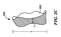
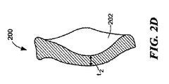
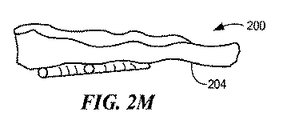
一実施形態は、面関節で使用するための間置デバイスである。デバイスは、面関節の関節面の間に挿入されるように構成される本体を含む。本体は、第1および第2の関節面ならびに第1および第2の端部を有する。第1の関節面は、デバイスが面関節の関節面の間に挿入されると、対向する関節面に対する動作に抵抗するように構成される輪郭を有する。第2の関節面は、デバイスが面関節の関節面の間に挿入されると、別の対向する関節面対する動作を容易にするように構成される。 One embodiment is an interposition device for use with facet joints. The device includes a body configured to be inserted between the articular surfaces of the facet joint. The body has first and second articulating surfaces and first and second ends. The first articular surface has a contour configured to resist movement relative to the opposing articular surface when the device is inserted between the articular surfaces of the facet joint. The second articulating surface is configured to facilitate movement relative to another opposing articular surface when the device is inserted between the articulating surfaces of the facet joint.
代替の実施形態は、以下の特色のうちの1つ以上を含んでもよい。第1の端部は、デバイスの中間部分に対して拡大することができる。第1の端部は、面関節の少なくとも1つの表面に係合するように構成される縁を形成し、それによって、面関節に対するデバイスの動作に抵抗することができる。第1の端部は、間置デバイスが面関節に埋め込まれると、関節間位置に位置するように構成することができるか、または代替として、第1の端部は、間置デバイスが面関節に埋め込まれると、関節外位置に位置するように構成することができる。 Alternative embodiments may include one or more of the following features. The first end can be enlarged relative to the middle portion of the device. The first end may form an edge configured to engage at least one surface of the facet joint, thereby resisting movement of the device relative to the facet joint. The first end can be configured to be located in an inter-articular position when the interposition device is implanted in a facet joint, or alternatively, the first end can be configured so that the interposition device is face-joint. It can be configured to be located at a position outside the joint when embedded in the joint.
第1の関節面の少なくとも一部分の輪郭は、対向する関節面の対応する輪郭に実質的に合致するように作製することができる。第1の関節面の少なくとも一部分は、対向する関節面の対応する輪郭の陰型を実質的に形成することができる。第1の関節面は、面関節に埋め込まれると、デバイスを固定するように構成することができる。第1の関節面の少なくとも一部分は、デバイスが面関節に埋め込まれると、対向する関節面の対応する部分と相互に噛合するように構成することができる。 The contour of at least a portion of the first articular surface can be made to substantially match the corresponding contour of the opposing articular surface. At least a portion of the first articular surface can substantially form a negative contour of the corresponding contour of the opposing articular surface. The first articular surface can be configured to secure the device when implanted in the facet joint. At least a portion of the first articular surface can be configured to interlock with a corresponding portion of the opposing articular surface when the device is implanted in the facet joint.
第2の関節面は、実質的に平滑であり得る。 The second articular surface can be substantially smooth.
第2の端部は、面関節の第1および第2の表面の間の空間を拡大するように、デバイスの中間部分に対して拡大することができる。 The second end can be enlarged relative to the middle portion of the device to enlarge the space between the first and second surfaces of the facet joint.
デバイスは、面関節にデバイスを固定するための取付機構、例えば、ピン、フィン、ネジ、または縫合も含むことができるが、限定されない。 The device can also include, but is not limited to, attachment mechanisms for securing the device to the facet joint, such as pins, fins, screws, or sutures.
別の実施形態は、面関節で使用するための患者特有のインプラントである。インプラントは、面関節の関節面の間に挿入されるように構成され、第1および第2の関節面を有する本体を含む。第1の関節面の少なくとも一部分は、面関節の第1の関節面の対応する部分に実質的に合致する。第2の関節面は、インプラントが面関節の第1および第2の関節面の間に配置されると、面関節の第2の関節面に係合し、かつそれに対して動くように構成される実質的に平滑な部分を有する。 Another embodiment is a patient specific implant for use in a facet joint. The implant is configured to be inserted between articular surfaces of a facet joint and includes a body having first and second articular surfaces. At least a portion of the first articular surface substantially matches a corresponding portion of the first articular surface of the facet joint. The second articular surface is configured to engage and move relative to the second articular surface of the facet joint when the implant is disposed between the first and second articular surfaces of the facet joint. Having a substantially smooth portion.
代替の実施形態は、以下の特色のうちの1つ以上を含んでもよい。インプラントは、デバイスの中間部分に対して拡大される第1の端部を含んでもよい。第1の端部は、面関節の一部に係合するように構成されるキャップを形成し、それによって、面関節に対するデバイスの動作に抵抗してもよい。第1の端部は、間置デバイスが面関節に埋め込まれると、関節間位置に位置するように構成することができる。第1の端部は、あるいは、間置デバイスが面関節に埋め込まれると、関節外位置に位置するように構成することができる。 Alternative embodiments may include one or more of the following features. The implant may include a first end that is enlarged relative to an intermediate portion of the device. The first end may form a cap configured to engage a portion of the facet joint, thereby resisting movement of the device relative to the facet joint. The first end can be configured to be located at the inter-joint position when the interposition device is implanted in the facet joint. The first end, or alternatively, can be configured to be located at the extra-articular position when the interposition device is implanted in the facet joint.
第1の関節面は、面関節に埋め込まれると、デバイスを固定するために使用することができる。 The first articular surface can be used to secure the device when implanted in the facet joint.
デバイスは、デバイスの中間部分に対して拡大される第1および第2の端部をさらに含むことができる。 The device can further include first and second ends that are enlarged relative to the middle portion of the device.
デバイスは、面関節にデバイスを固定するための取付機構、例えば、ピン、フィン、またはネジも含むことができるが、限定されない。 The device can also include, but is not limited to, attachment mechanisms for securing the device to the facet joint, such as pins, fins, or screws.
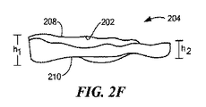
別の実施形態は、脊椎の一部分を減圧する際に使用するための間置デバイスである。デバイスは、面関節の関節面の間に挿入することができる本体を含む。本体は、第1および第2の関節面、第1の端部、および中間部分を有する。第1の関節面は、デバイスが適所にあると、対向する関節面に対して動くように構成される。第1の端部は、中間部分の対応する厚さより大きい、第1および第2の関節面の間の方向で測定される厚さを有する。第1の端部は、間置デバイスが埋め込まれると、少なくとも1つの方向への面関節に対する本体の動作に抵抗するように構成される。 Another embodiment is an interposition device for use in decompressing a portion of the spine. The device includes a body that can be inserted between the articular surfaces of the facet joint. The body has first and second articular surfaces, a first end, and an intermediate portion. The first articular surface is configured to move relative to the opposing articular surface when the device is in place. The first end has a thickness measured in a direction between the first and second articular surfaces that is greater than the corresponding thickness of the intermediate portion. The first end is configured to resist movement of the body relative to the facet joint in at least one direction when the interposition device is implanted.
代替の実施形態は、以下の特色のうちの1つ以上を含んでもよい。第2の関節面の少なくとも一部分は、第2の関節面の対応する輪郭に実質的に合致する輪郭を含むことができる。第2の関節面の少なくとも一部分は、第2の関節面の対応する部分の陰型を実質的に形成することができる。第2の関節面は、面関節に埋め込まれると、デバイスを固定するように構成することができる。第2の関節面の少なくとも一部分は、デバイスが面関節に埋め込まれると、第2の関節面の対応する部分と相互に噛合するように構成することができる。 Alternative embodiments may include one or more of the following features. At least a portion of the second articulating surface can include a contour that substantially matches a corresponding contour of the second articulating surface. At least a portion of the second articulating surface can substantially form a negative shape of a corresponding portion of the second articulating surface. The second articular surface can be configured to secure the device when implanted in the facet joint. At least a portion of the second articular surface can be configured to interdigitate with a corresponding portion of the second articular surface when the device is implanted in the facet joint.
第1の関節面は、実質的に平滑であり得る。 The first articular surface can be substantially smooth.
別の実施形態は、脊椎の一部分に対する圧力を軽減する際に使用するためのデバイスである。デバイスは、面関節の関節面の間に挿入されるように構成される本体を有する。本体は、第1および第2の関節面および端部を有する。第1の関節面は、デバイスが埋め込まれると、面関節の対応する第1の表面に係合するように構成される。第2の関節面は、面関節の対応する第2の表面に係合するように構成される。端部は、第1および第2の表面の間の方向で、デバイスの隣接する部分より比較的厚く、それによって、デバイスが面関節に埋め込まれると、面関節の第1および第2の表面の間の間隔を増加させる。 Another embodiment is a device for use in relieving pressure on a portion of the spine. The device has a body configured to be inserted between the articular surfaces of the facet joint. The body has first and second articulating surfaces and ends. The first articular surface is configured to engage a corresponding first surface of the facet joint when the device is implanted. The second articular surface is configured to engage a corresponding second surface of the facet joint. The end is relatively thicker than the adjacent portion of the device in the direction between the first and second surfaces, so that when the device is implanted in the facet joint, the end of the facet first and second surface Increase the interval between.
別の実施形態は、脊椎の一部分を減圧するための方法である。方法は、関節面の間の空間を拡張するように、面関節の第1および第2の関節面の間にインプラントを挿入するステップ、および第1および第2の表面が一定の期間にわたって拡張位置に留まるように、インプラントを面関節で安定させるステップを含む。結果として、脊椎の部分は、減圧する。 Another embodiment is a method for decompressing a portion of a spine. The method includes inserting an implant between the first and second articular surfaces of the facet joint to expand the space between the articular surfaces, and the first and second surfaces are in an expanded position over a period of time. So that the implant is stabilized at the face joints. As a result, the portion of the spine is decompressed.
代替の実施形態は、以下の特色のうちの1つ以上を含んでもよい。脊椎の隣接する間質腔に対する圧力を低減させことができる。脊椎に対する圧力に関連する痛みは、その後、低減させることができる。 Alternative embodiments may include one or more of the following features. The pressure on the adjacent interstitial space of the spine can be reduced. Pain associated with pressure on the spine can then be reduced.
(詳細な説明)
以下の説明は、任意の当業者が本発明の実施形態を作製し、使用することを可能にするために提示される。説明される実施形態への様々な修正は、当業者にとって容易に理解され、本明細書に規定される一般的原理は、添付される請求項によって規定される本発明の趣旨および範囲から逸脱することなく他の実施形態および用途に適用することができる。そのため、本発明の実施形態は、示される実施形態を限定することを目的とせず、本明細書に開示される原理および特色と一致する最も広い範囲に合致することを目的とする。開示される本発明の完全な理解を達成するために必要な程度で、本出願において挙げられる全ての交付済み特許、特許公報、ならびに特許出願の明細書および図面は、それら全体が本明細書に参考として援用される。
(Detailed explanation)
The following description is presented to enable any person skilled in the art to make and use embodiments of the invention. Various modifications to the described embodiments will be readily apparent to those skilled in the art, and the general principles defined herein will depart from the spirit and scope of the invention as defined by the appended claims. It can be applied to other embodiments and applications without. As such, embodiments of the present invention are not intended to limit the embodiments shown, but to the widest scope consistent with the principles and features disclosed herein. To the extent necessary to achieve a thorough understanding of the disclosed invention, all issued patents, patent publications, and patent application specifications and drawings cited in this application are hereby incorporated by reference in their entirety. Incorporated as a reference.
当業者によって理解されるように、本明細書において列挙される方法は、論理的に可能な、列挙された事象の任意の順序、および事象の列挙された順序で実行されてもよい。なお、値の範囲が提供される場合、その範囲の上限と下限との間の全ての介在する値およびその記述された範囲における任意の他の記述される、または介在する値は、本発明の実施形態内に包含されることが理解される。また、説明される発明の変化の任意の随意的な特色は、単独か、または本明細書に説明される特色のうちのいずれか1つ以上と組み合わせて明記および主張されてもよいことが意図される。 As will be appreciated by those skilled in the art, the methods listed herein may be performed in any order of the listed events and the listed order of events that are logically possible. It should be noted that where a range of values is provided, all intervening values between the upper and lower limits of the range and any other described or intervening values in the stated range are intended to It is understood that it is encompassed within the embodiment. Also, it is intended that any optional feature of the described inventive variation may be specified and claimed alone or in combination with any one or more of the features described herein. Is done.
本発明の実施形態の履行は、他に指定のない限り、当技術分野内におけるX線画像化および処理、X線トモシンセシス、Aスキャン、Bスキャン、およびCスキャンを含む超音波、コンピュータ断層撮影法(CTスキャン)、磁気共鳴映像法(MRI)、断層映像法、単光子放出型コンピュータ断層撮影(SPECT)、および陽電子放出型断層撮影法(PET)の従来のデジタル方法を使用することができる。そのような技術は、文献において完全に説明され、本明細書において説明される必要はない。例えば、X−Ray Structure Determination:A Practical Guide,2nd Edition,editors Stout and Jensen,1989,John Wiley & Sons,publisher;Body CT:A Practical Approach,editor Slone,1999,McGraw−Hill publisher;X−ray Diagnosis:A Physician’s Approach,editor Lam,1998 Springer−Verlag,publisher;およびDental Radiology:Understanding the X−Ray Image,editor Laetitia Brocklebank 1997,Oxford University Press publisherを参照されたい。The Essential Physics of Medical Imaging(2.sup.nd Ed.),Jerrold T.Bushberg,et al.も参照されたい。 Implementation of embodiments of the present invention includes ultrasound, computed tomography, including X-ray imaging and processing, X-ray tomosynthesis, A-scan, B-scan, and C-scan within the art, unless otherwise specified. Conventional digital methods such as (CT scan), magnetic resonance imaging (MRI), tomographic imaging, single photon emission computed tomography (SPECT), and positron emission tomography (PET) can be used. Such techniques are explained fully in the literature and need not be described herein. For example, X-Ray Structure Determination: A Practical Guide, 2nd Edition, editors Stout and Jensen, 1989, John Wiley & Sons, publisher; Body CT: A Practical Approach, editor Slone, 1999, McGraw-Hill publisher; X-ray Diagnosis : A Physician's Approach, editor Lam, 1998 Springer-Verlag, publisher; and Dental Radiology: Understanding the X-Ray Image, editor Laetitia Broc See lebank 1997, Oxford University Press publisher. The Essential Physics of Medical Imaging (2.sup.nd Ed.), Jerrold T., et al. Bushberg, et al. See also
本発明は、関節を修復するため、特に関節軟骨および軟骨下骨を修復するため、ならびに対象者への幅広い種類の軟骨および軟骨下骨修復材料の組み入れを容易にするための方法および組成を提供する。とりわけ、本明細書に説明される技術は、例えば、サイズ、軟骨厚さ、および/または軟骨下骨湾曲を含む湾曲に関して特定の対象者に適合するように、軟骨または軟骨下骨修復材料のカスタム化を可能にする。関節軟骨表面の形状(例えば、サイズ、厚さ、および/または湾曲)が、非損傷軟骨または対象者の本来の軟骨と正確にか、またはほぼ解剖学的に適合する場合、修復の成功は高まる。修復材料は、移植前に成形することができ、そのような成形は、例えば、欠陥の周囲にある任意の「正常」軟骨の湾曲または厚さに関する情報を提供する電子画像、および/または欠陥の下に横たわる骨の湾曲に基づくことができる。そのため、本発明の実施形態は、とりわけ、取付および間置設計による部分的または全関節置換術のための低侵襲方法を提供する。方法は、骨量の最小限の損失のみを必要とするか、または場合によっては必要としない。さらに、現在の技術とは異なり、本明細書に説明される方法は、インプラントと周囲または隣接軟骨および/または軟骨下骨との間の正確か、または近い解剖学的一致に到達することによって関節面の完全性を復元することに役立つ。 The present invention provides methods and compositions for repairing joints, particularly for repairing articular cartilage and subchondral bone, and for facilitating the incorporation of a wide variety of cartilage and subchondral bone repair materials into a subject. To do. In particular, the techniques described herein can be customized for cartilage or subchondral bone repair material to suit a particular subject with respect to curvature, including, for example, size, cartilage thickness, and / or subchondral bone curvature. Make it possible. Successful repair is enhanced when the shape (eg, size, thickness, and / or curvature) of the articular cartilage surface accurately or nearly anatomically matches the intact cartilage or the subject's original cartilage . The repair material can be shaped prior to implantation, such as an electronic image that provides information about the curvature or thickness of any “normal” cartilage around the defect, and / or the defect. It can be based on the curvature of the underlying bone. As such, embodiments of the present invention provide, among other things, a minimally invasive method for partial or total joint replacement with attachment and interposition designs. The method requires only minimal loss of bone mass or in some cases not required. Furthermore, unlike current technology, the methods described herein can be used to achieve a precise or close anatomical agreement between the implant and the surrounding or adjacent cartilage and / or subchondral bone. Helps restore the integrity of the surface.
本発明の実施形態の利点は、(i)関節修復の随意的カスタム化、それによる修復処置後の患者に対する有効性および快適度の強化、(ii)いくつかの実施形態における、執刀医が術中に修復される欠陥を測定する必要性の随意的な排除、(iii)執刀医が移植処置中に材料を成形する必要性の随意的な排除、(iv)骨または組織画像に基づくか、または術中プロービング技術に基づいて修復材料の湾曲を評価する方法の提供、(v)骨量の最小限の損失のみ、または場合によっては損失を伴わないで関節を修復する方法の提供、(vi)術後の関節適合性の改善、(vii)いくつかの実施形態における、術後の患者回復の改善、および(viii)可動域等の術後機能の改善を含むことができるが、これらに限定されない。 The advantages of embodiments of the present invention are: (i) optional customization of joint repair, thereby enhancing effectiveness and comfort for the patient after the repair procedure, (ii) in some embodiments, the surgeon is intraoperative (Iii) optional elimination of the need for the surgeon to shape the material during the implantation procedure, (iv) based on bone or tissue images, or Providing a method for assessing the curvature of the repair material based on intraoperative probing techniques, (v) Providing a method for repairing the joint with minimal or no loss of bone mass, (vi) Surgery Include, but are not limited to, improved joint compatibility later, (vii) improved patient recovery after surgery in some embodiments, and (viii) improved post-operative functions such as range of motion. .
そのため、本明細書に説明される方法は、欠陥(例えば、移植の部位)または関節面により正確に適合する関節修復材料の設計および使用を可能にし、したがって、関節の修復の改善を提供する。 As such, the methods described herein allow for the design and use of joint repair materials that more closely match a defect (eg, the site of implantation) or the articular surface, thus providing improved joint repair.
(関節および整合の評価)
本明細書に説明される方法および組成は、軟骨の疾病(例えば、変形性関節炎)、骨損傷、軟骨損傷、外傷、および/または酷使または年齢による変性によって生じる欠陥を治療するために使用することができる。本発明の実施形態は、とりわけ、健康管理医がそのような欠陥を評価し治療することを可能にする。対象の部分のサイズ、体積、および形状は、欠陥を有する軟骨の領域のみを含むことができるが、好ましくは、軟骨欠陥の周囲にある軟骨の接触する部分も含む。
(Evaluation of joints and alignment)
The methods and compositions described herein are used to treat cartilage diseases (eg, osteoarthritis), bone damage, cartilage damage, trauma, and / or defects caused by overuse or age degeneration. Can do. Embodiments of the present invention, among other things, allow health care physicians to assess and treat such defects. The size, volume, and shape of the portion of interest can include only the area of the cartilage that has the defect, but preferably also includes the contacting portion of the cartilage around the cartilage defect.
当業者によって理解されるように、サイズ、湾曲、および/または厚さ測定は、任意の好適な技術を使用して得ることができる。例えば、1次元、2次元、および/または3次元測定は、好適な機械的手段、レーザーデバイス、電磁気または光学追跡システム、鋳型、硬化しかつ「表面輪郭を記憶する」関節面に適用される材料、および/または当技術分野で周知の1つ以上の撮像技術を使用して得ることができる。測定は、非侵襲的に、および/または術中に(例えば、プローブまたは他の外科的デバイスを使用して)得ることができる。当業者によって理解されるように、修復デバイスの厚さは、患者の骨格による任意の既定の点および/または関節面上の任意の特定の場所での補正される軟骨および/または骨への損傷の深さで異なり得る。 As will be appreciated by those skilled in the art, size, curvature, and / or thickness measurements can be obtained using any suitable technique. For example, one-dimensional, two-dimensional, and / or three-dimensional measurements can be applied to suitable mechanical means, laser devices, electromagnetic or optical tracking systems, molds, cured and articulated surfaces that “store the surface contour” And / or can be obtained using one or more imaging techniques well known in the art. Measurements can be obtained non-invasively and / or intraoperatively (eg, using a probe or other surgical device). As will be appreciated by those skilled in the art, the thickness of the repair device is determined by the patient's skeleton at any given point and / or damage to the cartilage and / or bone corrected at any particular location on the articular surface. Can vary in depth.
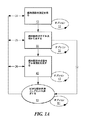
図1Aは、関節を評価する際に施術者によって取られるステップを示すフローチャートである。まず、施術者は、標的関節の測定を得る(10)。測定を得るステップは、関節の画像を撮ることによって遂行することができる。このステップは、必要に応じて繰り返して(11)、関節評価過程をさらに精緻化するために複数の画像を得ることができる。施術者が必要な測定を得ると、情報を使用して、評価されている標的関節のモデル表現を生成する(30)。このモデル表現は、局所解剖学的地図または画像の形態であり得る。関節のモデル表現は、1、2、または3次元であり得る。それは、身体的モデルを含むことができる。所望であれば、1つ以上のモデルを作製することができる(31)。本来のモデルもしくは後に作製されるモデルのいずれか、または両方を使用することができる。関節のモデル表現が生成された(30)後、施術者は、対向する関節表面の反射鏡を提供することによって、関節表面またはその組み合わせ上の、例えば、既存の軟骨から補正された条件における標的関節の投影モデル表現を随意に生成することができる(40)。再度、このステップは、必要に応じてか、または所望であれば、繰り返すことができる(41)。関節の局所解剖学的条件と関節の投影画像との間の差異を使用して、その後、施術者は、補正された関節構造を達成するために好適な関節インプラントを選択することができる(50)。当業者によって理解されるように、選択過程50は、所望の結果を達成するために、所望であれば、何度でも繰り返すことができる(51)。さらに、施術者は、例えば、X線を得ることによって標的関節の測定を得ることができ(10)、その後、好適な関節置換インプラントを選択することができる(50)ことが意図される。
FIG. 1A is a flowchart showing the steps taken by a practitioner when evaluating a joint. First, the practitioner obtains a measurement of the target joint (10). The step of obtaining a measurement can be accomplished by taking an image of the joint. This step can be repeated as needed (11) to obtain multiple images to further refine the joint evaluation process. Once the practitioner has the necessary measurements, the information is used to generate a model representation of the target joint being evaluated (30). This model representation may be in the form of a topographic map or image. The model representation of the joint can be one, two, or three dimensional. It can include a physical model. If desired, one or more models can be created (31). Either the original model or the model created later, or both can be used. After the model representation of the joint has been generated (30), the practitioner can provide a target on the joint surface or a combination thereof, eg, in a condition corrected from existing cartilage, by providing an opposing joint surface reflector. A projection model representation of the joint can optionally be generated (40). Again, this step can be repeated as needed or if desired (41). Using the difference between the local anatomical conditions of the joint and the projected image of the joint, the practitioner can then select a suitable joint implant to achieve the corrected joint structure (50 ). As will be appreciated by those skilled in the art, the
当業者によって理解されるように、施術者は、矢印32によって示されるように、標的関節のモデル表現を生成するステップ30から好適な関節置換インプラントを選択するステップ50へ直接進むことができる。さらに、好適な関節置換インプラントの選択50の後、標的関節の測定を得るステップ10、標的関節のモデル表現を生成するステップ30、および投影モデルを生成するステップ40は、流れ24、25、26によって示されるように順次にか、または並行して繰り返すことができる。
As will be appreciated by those skilled in the art, the practitioner can proceed directly from
図1Bは、関節を評価する際に施術者によって取られるステップを示す代替のフローチャートである。まず、施術者は、標的関節の測定を得る(10)。測定を得るステップは、関節の画像を撮ることによって遂行することができる。このステップは、必要に応じて繰り返して(11)、関節評価過程をさらに精緻化するために複数の画像を得ることができる。施術者が必要な測定を得ると、情報を使用して、評価されている標的関節のモデル表現を生成する(30)。このモデル表現は、局所解剖学的地図または画像の形態であり得る。関節のモデル表現は、1、2、または3次元であり得る。過程は、必要に応じてか、または所望であれば、繰り返すことができる(31)。それは、身体的モデルを含むことができる。関節のモデル表現が評価された(30)後、施術者は、補正された条件における標的関節の投影モデル表現を随意に生成することができる(40)。このステップは、必要に応じてか、または所望であれば、繰り返すことができる(41)。関節の局所解剖学的条件と関節の投影画像との間の差異を使用して、その後、施術者は、補正された関節構造を達成するために好適な関節インプラントを設計することができ(52)、所望のインプラントを達成するために、必要に応じて、何回でも設計過程を繰り返すことができる(53)。施術者は、レール、竜骨、縁、ペグ、十字形の幹、またはアンカー、クロスバー等の付加的特色を提供することが、標的関節におけるインプラントの性能を強化させるかどうかを評価することもできる。 FIG. 1B is an alternative flowchart showing the steps taken by the practitioner in evaluating the joint. First, the practitioner obtains a measurement of the target joint (10). The step of obtaining a measurement can be accomplished by taking an image of the joint. This step can be repeated as needed (11) to obtain multiple images to further refine the joint evaluation process. Once the practitioner has the necessary measurements, the information is used to generate a model representation of the target joint being evaluated (30). This model representation may be in the form of a topographic map or image. The model representation of the joint can be one, two, or three dimensional. The process can be repeated as needed or if desired (31). It can include a physical model. After the joint model representation has been evaluated (30), the practitioner can optionally generate a projection model representation of the target joint in the corrected conditions (40). This step can be repeated (41) as needed or desired. Using the difference between the local anatomical condition of the joint and the projected image of the joint, the practitioner can then design a suitable joint implant to achieve a corrected joint structure (52 ), The design process can be repeated as many times as necessary to achieve the desired implant (53). The practitioner can also assess whether providing additional features such as rails, keel, rims, pegs, cruciform trunks, or anchors, crossbars, etc. will enhance the performance of the implant at the target joint .
当業者によって理解されるように、施術者は、矢印38によって示されるように、標的関節のモデル表現を生成するステップ30から好適な関節置換インプラントを設計するステップ52へ直接進むことができる。上記で示される流れと同様に、好適な関節置換インプラントの設計(52)の後、標的関節の測定を得るステップ10、標的関節のモデル表現を生成するステップ30、および投影モデルを生成するステップ40は、流れ42、43、44によって示されるように順次にか、または並行して繰り返すことができる。
As will be appreciated by those skilled in the art, the practitioner can proceed directly from
図1Cは、患者のためのインプラントを選択する過程を示すフローチャートである。まず、上述の技術または本発明の実施形態が履行される時に好適かつ当技術分野で周知の技術を使用して、罹患軟骨または軟骨損失の部分のサイズが測定される(100)。このステップは、所望であれば、複数回繰り返すことができる(101)。軟骨欠陥のサイズが測定されると、隣接する軟骨の厚さを随意に測定することができる(110)。この過程も、所望であれば、繰り返すことができる(111)。軟骨損失を測定したか、または隣接する軟骨の厚さを測定した後のいずれかに、関節面の湾曲が測定される(120)。あるいは、軟骨下骨を測定することができる。理解されるように、修復されている関節の表面か、またはインプラント表面のための最良の設計の開発を容易にするために噛合面の測定を取ることができる。 FIG. 1C is a flowchart illustrating a process of selecting an implant for a patient. First, the size of the affected cartilage or cartilage loss portion is measured (100) using techniques described above, or techniques suitable and well known in the art when the embodiments of the present invention are implemented. This step can be repeated multiple times if desired (101). Once the size of the cartilage defect is measured, the thickness of the adjacent cartilage can optionally be measured (110). This process can also be repeated (111) if desired. Either after measuring cartilage loss or measuring the thickness of adjacent cartilage, the curvature of the articular surface is measured (120). Alternatively, subchondral bone can be measured. As will be appreciated, a measurement of the mating surface can be taken to facilitate the development of the best design for the surface of the joint being repaired or for the implant surface.
表面が測定されると、使用者は、インプラントのライブラリに含有される最も良く適合するインプラントを選択する(130)か、または患者特有のインプラントを生成する(132)。これらのステップは、患者のための最も良く適合するインプラントを達成するために、所望であれば、または必要に応じて、繰り返すことができる(131)、(133)。当業者によって理解されるように、インプラントを選択するか、または設計する過程は、デバイスの表面が、患者の関節表面に対する良い適合を達成することを確実にするために、患者のMRIまたはX線に含有される情報に対して試験することができる。試験は、例えば、インプラント画像を患者の関節に対する画像上に重ねることによって遂行することができる。好適なインプラントが選択されたか、または設計されたことが決定されると、インプラント部位は、例えば、軟骨または骨を関節表面から除去することによって調製することができる(140)か、またはインプラントは、関節へ配置することができる(150)。 Once the surface is measured, the user selects the best-fit implant contained in the implant library (130) or generates a patient-specific implant (132). These steps can be repeated (131), (133) if desired or necessary to achieve a best-fit implant for the patient. As will be appreciated by those skilled in the art, the process of selecting or designing the implant will ensure that the surface of the device achieves a good fit to the patient's articular surface, such as MRI or Can be tested against the information contained therein. The test can be accomplished, for example, by overlaying the implant image on the image for the patient's joint. Once it is determined that a suitable implant has been selected or designed, the implant site can be prepared (140), for example, by removing cartilage or bone from the joint surface, Can be placed in a joint (150).
選択されたか、または設計された関節インプラントは、天然の関節構造を複製する対向する関節表面に対する噛合面を提示しながら、関節の既存の表面との解剖学的または近い解剖学的適合を達成する。この場合、関節の既存の表面、および関節の所望の得られる表面の両方を評価することができる。この技術は、骨に固定されないインプラントのために特に有用である。 Selected or engineered joint implants achieve an anatomical or near anatomical fit with the existing surface of the joint while presenting a mating surface to the opposing joint surface that replicates the natural joint structure . In this case, both the existing surface of the joint and the desired resulting surface of the joint can be evaluated. This technique is particularly useful for implants that are not fixed to bone.
当業者によって理解されるように、医師、または本発明の実施形態を履行する他の人は、標的関節の測定を得(10)、その後、好適な関節置換インプラントの設計(52)または選択(50)のいずれかを行うことができる。 As will be appreciated by those skilled in the art, a physician or other person implementing an embodiment of the present invention obtains measurements of the target joint (10) and then designs (52) or selects a suitable joint replacement implant ( 50).
(修復材料)
幅広い種類の材料は、本発明の履行における使用を見出し、プラスチック、金属、結晶のない金属、セラミック、生物材料(例えば、コラーゲンまたは他の細胞外マトリクス材料)、ヒドロキシアパタイト、細胞(例えば、幹細胞、軟骨細胞等)、またはそれらの組み合わせを含むが、これらに限定されない。欠陥および関節面および/または軟骨下骨に関して得られる情報(例えば、測定)に基づき、修復材料は、形成または選択することができる。さらに、本明細書に説明されるこれらの技術のうちの1つ以上を使用して、特定の軟骨欠陥に、または特定の骨表面上に適合する湾曲を有する軟骨または骨置換または再生材料は、関節面の輪郭および形状に従い、周囲軟骨の厚さに随意に一致する。修復材料は、材料の任意の組み合わせを含むことができ、通常は、少なくとも1つの非柔軟な材料、例えば、容易に屈折または変更されない材料を含む。
(Restoration material)
A wide variety of materials find use in the implementation of the present invention, plastics, metals, metal without crystals, ceramics, biological materials (eg, collagen or other extracellular matrix materials), hydroxyapatite, cells (eg, stem cells, Chondrocytes, etc.), or a combination thereof, but is not limited thereto. Based on the defect and information obtained (eg, measurements) on the articular surface and / or subchondral bone, a repair material can be formed or selected. Furthermore, using one or more of these techniques described herein, cartilage or bone replacement or regeneration material having a curvature that fits into a specific cartilage defect or on a specific bone surface is According to the contour and shape of the articular surface, it optionally corresponds to the thickness of the surrounding cartilage. The restorative material can include any combination of materials, and typically includes at least one non-flexible material, such as a material that is not easily refracted or altered.
(A.金属および高分子修復材料)
現在、関節修復システムは、例えば、下層の骨(例えば、人工膝の場合における大腿骨)に固定される人工器官を含む、金属および/または高分子材料をしばしば使用する。例えば、2001年3月20日交付のAfriat,et al.の米国特許第6,203,576号および2001年11月27日交付のOgle,et al.の米国特許第6,322,588号、ならびに本明細書に挙げられる参考文献を参照されたい。幅広い種類の金属は、本発明の実施形態の履行において有用であり、任意の基準に基づいて選択することができる。例えば、材料選択は、剛性の所望の程度を与える弾力性に基づくことができる。好適な金属の限定されない例としては、銀、金、白金、パラジウム、イリジウム、銅、錫、鉛、アンチモン、ビスマス、亜鉛、チタニウム、コバルト、ステンレス鋼、ニッケル、鉄合金、Elgiloy.RTM.等のコバルト合金、コバルトクロムニッケル合金、およびMP35N、ニッケルコバルトクロムモリブデン合金、およびNitinol.RTM.、ニッケルチタニウム合金、アルミニウム、マンガン、鉄、タンタル、Liquidmetal.RTM.合金等の結晶のない金属(LiquidMetal Technologiesより入手可能、www.liquidmetal.com)、例えば、患者の体液または組織に接触している埋め込まれた基質の石灰化を抑制するための多価金属イオンを徐々に形成することができる他の金属、ならびにそれらの組み合わせが挙げられる。
(A. Metal and polymer restoration materials)
Currently, joint repair systems often use metallic and / or polymeric materials, including, for example, prosthetic devices that are secured to the underlying bone (eg, the femur in the case of a prosthetic knee). For example, Afriat, et al. US Pat. No. 6,203,576 and Ogle, et al. Issued November 27, 2001. U.S. Pat. No. 6,322,588, as well as references cited herein. A wide variety of metals are useful in the implementation of embodiments of the present invention and can be selected based on any criteria. For example, material selection can be based on elasticity that provides the desired degree of stiffness. Non-limiting examples of suitable metals include silver, gold, platinum, palladium, iridium, copper, tin, lead, antimony, bismuth, zinc, titanium, cobalt, stainless steel, nickel, iron alloys, Elgiloy. RTM. Cobalt alloys, such as cobalt chrome nickel alloys, and MP35N, nickel cobalt chrome molybdenum alloys, and Nitinol. RTM. , Nickel titanium alloy, aluminum, manganese, iron, tantalum, Liquidmetal. RTM. Crystalline metals such as alloys (available from LiquidMetal Technologies, www.liquidmetal.com), for example, polyvalent metal ions to inhibit calcification of implanted substrates in contact with patient fluids or tissues Other metals that can be formed gradually, as well as combinations thereof, can be mentioned.
好適な合成ポリマーとしては、ポリアミド(例えば、ナイロン)、ポリエステル、ポリスチレン、ポリアクリル酸塩、ビニルポリマー、(例えば、ポリエチレン、ポリテトラフルオロエチレン、ポリプロピレン、およびポリ塩化ビニル)、ポリカーボネート、ポリウレタン、ポリジメチルシロキサン、酢酸セルロース、ポリメチルメタクリレート、ポリエーテルエーテルケトン、エチレン酢酸ビニル、ポリスルホン、ニトロセルロース、同様のコポリマー、およびそれらの混合物が挙げられるが、限定されない。デキストラン、ヒドロキシエチルでんぷん、ゼラチンの誘導体、ポリビニルピロリドン、ポリビニルアルコール、ポリ[N−(2−ヒドロキシプロピル)メタクリルアミド]、ポリ(ヒドロキシ酸)、ポリ(イプシロン−カプロラクトン)、ポリ乳酸、ポリグリコール酸、ポリ(ジメチルグリコール酸)、ポリ(ヒドロキシ酪酸)等の生体吸収性合成ポリマーも使用することができ、同様のコポリマーも使用することができる。 Suitable synthetic polymers include polyamide (eg, nylon), polyester, polystyrene, polyacrylate, vinyl polymer (eg, polyethylene, polytetrafluoroethylene, polypropylene, and polyvinyl chloride), polycarbonate, polyurethane, polydimethyl Examples include, but are not limited to, siloxane, cellulose acetate, polymethyl methacrylate, polyether ether ketone, ethylene vinyl acetate, polysulfone, nitrocellulose, similar copolymers, and mixtures thereof. Dextran, hydroxyethyl starch, gelatin derivatives, polyvinylpyrrolidone, polyvinyl alcohol, poly [N- (2-hydroxypropyl) methacrylamide], poly (hydroxy acid), poly (epsilon-caprolactone), polylactic acid, polyglycolic acid, Bioabsorbable synthetic polymers such as poly (dimethyl glycolic acid) and poly (hydroxybutyric acid) can also be used, and similar copolymers can also be used.
他の材料、例えば、ポリエーテルエーテルケトン(PEEK.RTM.)として周知のポリケトンも適切である。これは、英国のVictrex of Lancashire(Victrexは、www.matweb.comで見られるか、またはBoedeker www.boedeker.comを参照されたい)から入手可能な医療移植用に認可された無充填PEEKである、材料PEEK450Gを含む。この材料の他の源としては、インドのPanoliにあるGharda(www.ghardapolymers.com)が挙げられる。 Other materials are also suitable, such as the polyketone known as polyetheretherketone (PEEK.RTM.). This is an unfilled PEEK approved for medical transplantation available from the UK's Victrex of Lanciaire (Victrex can be found at www.matweb.com or see Bodeker www.bodeker.com) Including material PEEK450G. Other sources of this material include Gharda (www.ghardapolymers.com) in Panoli, India.
選択される材料も充填することができることに留意するべきである。例えば、30%ガラス充填または30%カーボン充填等の他の等級のPEEKも、そのような材料が、FDA、または他の取締機関によって、埋め込み型デバイスにおける使用が許可されることを条件に利用可能であり、意図される。ガラス充填のPEEKは、無充填であるその部分に対して、PEEKの膨張率を低下させ、曲げ弾性率を増加させる。得られた生成物は、強度、剛性、または安定性の改善のために理想的であることが周知である。カーボン充填のPEEKは、PEEKの圧縮強度および剛性を強化させ、その膨張率を低下させることが周知である。カーボン充填のPEEKは、摩耗抵抗および載荷能力を提供する。 It should be noted that the selected material can also be filled. Other grades of PEEK, such as 30% glass filling or 30% carbon filling, are also available, provided that such materials are approved for use in implantable devices by the FDA or other regulatory agencies. And intended. Glass-filled PEEK reduces the expansion coefficient of PEEK and increases the flexural modulus relative to the unfilled part. It is well known that the resulting product is ideal for improved strength, stiffness, or stability. It is well known that carbon-filled PEEK enhances the compressive strength and stiffness of PEEK and lowers its expansion rate. Carbon filled PEEK provides wear resistance and loading capacity.
理解されるように、疲労に抵抗し、良い記憶力を有し、可撓性および/または屈折可能であり、非常に低い吸湿、ならびに摩耗および/または耐摩耗性を有する、他の好適な同様に生体適合性のある熱可塑性または熱可塑性重縮合材料は、本発明の実施形態の範囲から逸脱することなく使用することができる。インプラントは、ポリエーテルケトンケトン(PEKK)から成ることもできる。 As will be appreciated, other suitable as well, which resists fatigue, has good memory, is flexible and / or refractive, has very low moisture absorption, and wear and / or wear resistance Biocompatible thermoplastics or thermoplastic polycondensation materials can be used without departing from the scope of embodiments of the present invention. The implant can also consist of polyether ketone ketone (PEKK).
使用することができる他の材料としては、ポリエーテルケトン(PEK)、ポリエーテルケトンエーテルケトンケトン(PEKEKK)、およびポリエーテルエーテルケトンケトン(PEEKK)、ならびに概してポリアリールエーテルエーテルケトンが挙げられる。さらに他のポリケトン、および他の熱可塑性物質を使用することができる。 Other materials that can be used include polyetherketone (PEK), polyetherketone etherketoneketone (PEKEKK), and polyetheretherketoneketone (PEEKK), and generally polyaryletheretherketone. Still other polyketones and other thermoplastics can be used.
インプラントのために使用することができる適切なポリマーは、その全体が本明細書に参考として援用される、以下の文書を参照することができる。これらの文書としては、それぞれ、それら全体が本明細書に参考として援用される、2002年1月10日付、表題Bio−Compatible Polymeric MaterialsのPCT公開第WO02/02158A1号、2002年1月3日付、表題Bio−Compatible Polymeric MaterialsのPCT公開第WO02/00275A1号、および2002年1月3日付、表題Bio−Compatible Polymeric MaterialsのPCT公開第WO02/00270A1号が挙げられる。 For suitable polymers that can be used for implants, reference can be made to the following documents, which are hereby incorporated by reference in their entirety: These documents, each of which is incorporated herein by reference in its entirety, dated January 10, 2002, title Bio-Compatible Polymeric Materials PCT Publication No. WO 02 / 02158A1, dated January 3, 2002, PCT Publication No. WO02 / 00275A1 of the title Bio-Compatible Polymer Materials and PCT Publication No. WO 02 / 00270A1 of the title Bio-Compatible Polymer Materials dated January 3, 2002.
ポリマーは、従来のポリマー処理方法を含む任意の種々のアプローチによって調製することができる。好ましいアプローチとしては、例えば、有意な構造的特色を伴うポリマー構成要素の製造に好適である射出成形、およびRIM成形およびステレオリソグラフィー等のラピッドプロトタイピングアプローチが挙げられる。基質は、金属コーティングの組み込みを容易にするための物理的研磨または化学的変化のいずれかによって、ざらつきがあるか、または多孔性にすることができる。押し出し、注入、圧縮成形、および/または機械加工技術等の他の過程も適切である。通常は、ポリマーは、その物理的および機械的特性に対して選択され、関節表面の間の物理的負荷を携持し、広げるために好適である。 The polymer can be prepared by any of a variety of approaches including conventional polymer processing methods. Preferred approaches include, for example, injection molding that is suitable for the production of polymer components with significant structural features, and rapid prototyping approaches such as RIM molding and stereolithography. The substrate can be roughened or made porous by either physical polishing or chemical changes to facilitate the incorporation of the metal coating. Other processes such as extrusion, injection, compression molding, and / or machining techniques are also suitable. Typically, the polymer is selected for its physical and mechanical properties and is suitable for carrying and spreading the physical load between the joint surfaces.
1つ以上の金属および/またはポリマーは、相互に組み合わせて使用することができる。例えば、1つ以上の金属含有基質は、1つ以上の領域においてポリマーでコーティングすることができるか、または代替として、1つ以上のポリマー含有基質は、1つ以上の金属で1つ以上の領域においてコーティングすることができる。 One or more metals and / or polymers can be used in combination with each other. For example, one or more metal-containing substrates can be coated with a polymer in one or more regions, or alternatively, one or more polymer-containing substrates are one or more regions with one or more metals. Can be coated.
システムまたは人工器官は、多孔性であり得るか、または多孔性コーティングされ得る。多孔性表面構成要素は、金属、セラミック、およびポリマーを含む様々な材料で作製することができる。これらの表面構成要素は、様々な金属で形成される数多くの構造的コアに様々な手段によって順に固定することができる。好適な多孔性コーティングとしては、金属、セラミック、高分子(例えば、シリコーンゴム等の生物学的に中性のエラストマー、テレフタル酸ポリエチレンおよび/またはそれらの組み合わせ)、またはそれらの組み合わせが挙げられるが、これらに限定されない。例えば、1971年9月20日交付のHahnの米国特許第3,605,123号、1974年5月7日交付のTronzoの米国特許第3,808,606号、および1974年10月29日交付のTronzoの米国特許第3,843,975号、1967年4月18日交付のSmith米国特許第3,314,420号、1976年10月26日交付のScharbachの米国特許第3,987,499号、およびGerman Oftenlegungsschrift米国特許第2,306,552号を参照されたい。1つ以上のコーティング層が存在し得、層は、同じか、異なる多孔率を有することができる。例えば、1976年2月17日交付のKahn,et al.の米国特許第3,938,198号を参照されたい。 The system or prosthesis can be porous or can be porous coated. Porous surface components can be made of a variety of materials including metals, ceramics, and polymers. These surface components can be secured in sequence by various means to a number of structural cores formed of various metals. Suitable porous coatings include metals, ceramics, polymers (eg, biologically neutral elastomers such as silicone rubber, polyethylene terephthalate and / or combinations thereof), or combinations thereof, It is not limited to these. For example, Hahn, US Pat. No. 3,605,123, issued September 20, 1971, Tronzo, US Pat. No. 3,808,606, issued May 7, 1974, and October 29, 1974 US Pat. No. 3,843,975 issued to Tronzo, Smith US Pat. No. 3,314,420 issued April 18, 1967, and Scharbach US Pat. No. 3,987,499 issued Oct. 26, 1976. No. and German Oftenlegungsschrift US Pat. No. 2,306,552. There can be one or more coating layers, and the layers can have the same or different porosities. For example, Kahn, et al., Issued February 17, 1976. U.S. Pat. No. 3,938,198.
コーティングは、互いにつながった細孔の内部ネットワークでコーティングを形成するように硬化されるまで、コアを粉末ポリマーで囲い、加熱することによって塗布することができる。細孔のねじれ(例えば、細孔を通過する経路の直径までの長さの寸法)は、人工デバイスに対して使用するそのようなコーティングの可能な成功を評価する際に重要であり得る。1980年7月22日交付のMorrisの米国特許第4,213,816号も参照されたい。多孔性コーティングは、粉末の形態で塗布することができ、物品を全体として、粉末を基質に結合させる高温に供することができる。好適なポリマーおよび/または粉末コーティングの選択は、例えば、それぞれのメルトインデックスに基づいて、本明細書に挙げられる教示および参考文献を考慮して決定することができる。 The coating can be applied by surrounding the core with a powdered polymer and heating until cured to form a coating with an internal network of interconnected pores. Pore twist (eg, length dimension up to the diameter of the path through the pore) can be important in assessing the possible success of such coatings used for artificial devices. See also Morris, U.S. Pat. No. 4,213,816 issued July 22, 1980. The porous coating can be applied in the form of a powder and the article as a whole can be subjected to high temperatures that bind the powder to the substrate. The selection of a suitable polymer and / or powder coating can be determined in view of the teachings and references given herein, for example, based on the respective melt index.
(B.生物学的修復材料)
修復材料は、単独でか、または非生物材料と組み合わせてのいずれかで1つ以上の生物材料を含むこともできる。例えば、任意のベース材料を設計または成形することができ、胎児軟骨細胞等の好適な軟骨置換または再生材料は、ベースに適用することができる。その後、細胞は、軟骨欠陥の周囲にある軟骨の厚さ(および/または湾曲)が到達されるまで、ベースと併せて成長することができる。培養、体外、および体内で様々な基質上で細胞(例えば、軟骨細胞)を成長させるための条件は、例えば、1995年12月26日交付のSlivka et al.の米国特許第5,478,739号、1998年12月1日交付のNaughton et al.の米国特許第5,842,477号、2001年9月4日交付のVibe−Hansen et al.の米国特許第6,283,980号、および2002年4月2日交付のSalzmann et al.の米国特許第6,365,405号において説明される。好適な基質の限定されない例としては、プラスチック、組織足場、骨置換材料(例えば、ヒドロキシアパタイト、生体吸収性材料)、または軟骨置換もしくは再生材料をその上で成長させるために好適な任意の他の材料が挙げられる。
(B. Biological Restoration Material)
The restorative material can also include one or more biological materials, either alone or in combination with non-biological materials. For example, any base material can be designed or molded and a suitable cartilage replacement or regeneration material such as fetal chondrocytes can be applied to the base. The cells can then grow in conjunction with the base until the cartilage thickness (and / or curvature) around the cartilage defect is reached. Conditions for growing cells (eg, chondrocytes) on various substrates in culture, in vitro, and in the body are described, for example, in Sliveka et al., Issued December 26, 1995. U.S. Pat. No. 5,478,739, issued December 1, 1998 to Naughton et al. U.S. Pat. No. 5,842,477, issued September 4, 2001 to Vive-Hansen et al. U.S. Pat. No. 6,283,980 and Salzmann et al. U.S. Pat. No. 6,365,405. Non-limiting examples of suitable substrates include plastics, tissue scaffolds, bone replacement materials (eg, hydroxyapatite, bioabsorbable materials), or any other suitable for growing cartilage replacement or regeneration materials thereon Materials.
生物学的ポリマーは、自然発生であるか、または発酵等によって体外で産生することができる。好適な生物学的ポリマーとしては、コラーゲン、エラスチン、絹、ケラチン、ゼラチン、ポリアミノ酸、腸線縫合糸、多糖(例えば、セルロースおよびでんぷん)、およびそれらの混合物が挙げられるが、これらに限定されない。生物学的ポリマーは、生体吸収性であり得る。 Biological polymers can be naturally occurring or produced outside the body, such as by fermentation. Suitable biological polymers include, but are not limited to, collagen, elastin, silk, keratin, gelatin, polyamino acids, intestinal sutures, polysaccharides (eg, cellulose and starch), and mixtures thereof. The biological polymer can be bioabsorbable.
本明細書に説明される方法において使用される生物材料は、自家移植片(同じ対象者から)、同種移植片(同種の別の個体から)、および/または異種移植片(別の種から)であり得る。2002年3月21日公開のAlexander et al.の国際公開第02/22014号および1997年8月7日公開のLeeの同第97/27885号も参照されたい。ある実施形態では、自家移植材料は、材料の再吸収、炎症、および/またはインプラント部位の周囲にある組織の瘢痕化を含む、宿主への免疫学的合併症の低リスクを持つことができるため、好ましい。 The biological material used in the methods described herein can be an autograft (from the same subject), an allograft (from another individual of the same species), and / or a xenograft (from another species). It can be. Alexander et al., Published March 21, 2002. See also WO 02/22014 and Lee 97/27885, published August 7, 1997. In certain embodiments, the autograft material can have a low risk of immunological complications to the host, including material resorption, inflammation, and / or scarring of the tissue surrounding the implant site. ,preferable.
本発明の一実施形態では、プローブを使用して、ドナー部位から組織を収穫し、被移植部を調製する。ドナー部位は、異種移植片、同種移植片、または自家移植片に位置することができる。プローブは、ドナー組織サンプルと被移植部との間の良い解剖学的一致を達成するために使用される。プローブは、ドナー組織サンプルと被移植部との間の完全か、またはほぼ完全な一致を達成するように特異的に設計される。プローブは、例えば、円筒形であり得る。プローブの遠位端は、通常は、組織貫通を容易にするために鋭い。さらに、プローブの遠位端は、通常は、組織を受け入れるために空洞である。プローブは、その遠位端から画定された距離、例えば、遠位端から1cmのところに端を有することができ、端は、収穫するための組織貫通の確定された深さを達成するために使用することができる。端は、外部にあり得るか、またはプローブの空洞部分の内部にあり得る。例えば、整形外科医は、プローブを取り、物理的圧力でそれを、軟骨、軟骨下骨、および膝関節等の関節の場合、下層の骨髄に前進させることができる。整形外科医は、外または内端が軟骨表面に到達するまで、プローブを前進させる。その点で、端は、さらなる組織貫通を防止し、それによって、一定かつ再現可能な組織貫通を達成する。プローブの遠位端は、1つ以上のブレード、鋸歯状の構造、または組織切断機構を含むことができる。例えば、プローブの遠位端は、いくつかの小さいブレードから成る虹彩様機構を含むことができる。ブレードは、手動、電動、または電気的機構を使用して動くことができ、それによって、組織を切り開き、組織サンプルを下層組織から分離する。通常は、これは、ドナーおよびレシピエントにおいて繰り返される。虹彩形状のブレード機構の場合、個々のブレードは、虹彩を閉じるように動くことができ、それによって、組織サンプルをドナー部位から分離する。 In one embodiment of the invention, a probe is used to harvest tissue from a donor site and prepare a transplant. The donor site can be located in a xenograft, allograft, or autograft. The probe is used to achieve a good anatomical match between the donor tissue sample and the transplant. The probe is specifically designed to achieve a complete or near perfect match between the donor tissue sample and the recipient. The probe can be cylindrical, for example. The distal end of the probe is usually sharp to facilitate tissue penetration. Furthermore, the distal end of the probe is typically a cavity for receiving tissue. The probe can have an end defined a distance from its distal end, eg, 1 cm from the distal end, the end to achieve a defined depth of tissue penetration for harvesting Can be used. The ends can be external or can be internal to the hollow portion of the probe. For example, an orthopedic surgeon can take a probe and, with physical pressure, advance it to the underlying bone marrow in the case of joints such as cartilage, subchondral bone, and knee joints. The orthopedic surgeon advances the probe until the outer or inner edge reaches the cartilage surface. In that regard, the edge prevents further tissue penetration, thereby achieving constant and reproducible tissue penetration. The distal end of the probe can include one or more blades, serrated structures, or tissue cutting mechanisms. For example, the distal end of the probe can include an iris-like mechanism consisting of several small blades. The blade can be moved using manual, motorized, or electrical mechanisms, thereby cutting tissue and separating tissue samples from underlying tissue. Usually this is repeated in the donor and recipient. In the case of an iris shaped blade mechanism, the individual blades can move to close the iris, thereby separating the tissue sample from the donor site.
本発明の別の実施形態では、レーザーデバイスまたは高周波デバイスは、プローブの遠位端の内部で一体化することができる。レーザーデバイスまたは高周波デバイスは、組織を切り開き、組織サンプルを下層組織から分離するために使用することができる。 In another embodiment of the present invention, the laser device or high frequency device can be integrated within the distal end of the probe. Laser devices or radio frequency devices can be used to cut tissue and separate tissue samples from underlying tissue.
本発明の一実施形態では、同じプローブを、ドナーおよびレシピエントにおいて使用することができる。別の実施形態では、わずかに異なる物理的寸法の同様の形状のプローブを使用することができる。例えば、レシピエントにおいて使用されるプローブは、ドナーにおいて使用されるものよりわずかに小さくてもよく、それによって、組織サンプルまたは組織移植と被移植部との間のきつい適合を達成する。レシピエントにおいて使用されるプローブも、ドナーにおいて使用されるものよりわずかに短くてもよく、それによって、ドナー材料における下層組織からの組織サンプルの分離または切断中に損失される任意の組織を補正する。 In one embodiment of the invention, the same probe can be used in the donor and recipient. In another embodiment, a similarly shaped probe with slightly different physical dimensions can be used. For example, the probe used in the recipient may be slightly smaller than that used in the donor, thereby achieving a tight fit between the tissue sample or tissue transplant and the recipient. The probe used in the recipient may also be slightly shorter than that used in the donor, thereby correcting any tissue lost during the separation or cutting of the tissue sample from the underlying tissue in the donor material. .
任意の生物学的修復材料は、細菌、ウイルス、酵母菌、カビ、マイコプラズマ、および寄生生物等の生物学的汚染物質を不活性化するために滅菌することができる。滅菌は、任意の好適な技術、例えば、ガンマ放射等の放射を使用して行うことができる。 Any biological repair material can be sterilized to inactivate biological contaminants such as bacteria, viruses, yeasts, molds, mycoplasmas, and parasites. Sterilization can be performed using any suitable technique, for example, radiation such as gamma radiation.
本明細書に説明される任意の生物材料は、ロボットデバイスの使用によって収穫することができる。ロボットデバイスは、組織収穫のための電子画像からの情報を使用することができる。 Any biological material described herein can be harvested through the use of robotic devices. The robotic device can use information from electronic images for tissue harvesting.
ある実施形態では、軟骨置換材料は、特定の生化学的組成を有することができる。例えば、欠陥の周囲にある軟骨の生化学的組成は、組織サンプルを取ること、および化学分析によってか、または撮像技術によって評価することができる。例えば、Alexanderの国際公開02/22014号では、軟骨内のグリコサミノグリカン含有量を監視するための関節軟骨の画像化のためのガドリニウムの使用が説明される。そして、軟骨置換または再生材料は、移植部位の周囲にある軟骨の生化学的組成と同様のものを達成する方法で作製または培養することができる。所望の生化学的組成を達成するために使用される培養条件としては、例えば、様々な濃度を挙げることができる。軟骨置換または再生材料の生化学的組成は、例えば、ある栄養素および成長因子の濃度および暴露回数を制御することによって影響を与えることができる。 In certain embodiments, the cartilage replacement material can have a specific biochemical composition. For example, the biochemical composition of cartilage around the defect can be assessed by taking tissue samples and by chemical analysis or by imaging techniques. For example, Alexander WO 02/22014 describes the use of gadolinium for imaging articular cartilage to monitor glycosaminoglycan content in cartilage. The cartilage replacement or regeneration material can then be made or cultured in a manner that achieves a similar biochemical composition of cartilage around the transplant site. The culture conditions used to achieve the desired biochemical composition can include, for example, various concentrations. The biochemical composition of the cartilage replacement or regeneration material can be influenced, for example, by controlling the concentration and number of exposures of certain nutrients and growth factors.
(デバイス設計)
(A.軟骨および骨モデル)
軟骨または下層の骨の厚さおよび湾曲に関する情報を使用して、関節軟骨および下層の骨の表面の物理的モデルを作製することができる。この物理的モデルは、関節内の制限された面積の代理であり得るか、または関節全体を包含することができる。このモデルは、半月板の有無、および軟骨の一部または全部の有無を考慮することもできる。例えば、膝関節において、物理的モデルは、内側または外側大腿顆、両大腿顆およびノッチ領域、内側脛骨プラトー、外側脛骨プラトー、脛骨プラトー全体、内側膝蓋骨、外側膝蓋骨、膝蓋骨全体、または関節全体のみを包含することができる。軟骨の罹患部の場所は、例えば、3D座標系、または国際公開第02/22014号に説明される3Dユークリッド距離を使用して決定することができる。
(Device design)
(A. Cartilage and bone model)
Information regarding the thickness and curvature of cartilage or underlying bone can be used to create a physical model of the surface of articular cartilage and underlying bone. This physical model can be a surrogate for a limited area within the joint or can encompass the entire joint. This model can also consider the presence or absence of the meniscus and the presence or absence of some or all of the cartilage. For example, in the knee joint, the physical model can be the medial or lateral femoral condyle, both femoral condyles and notch regions, medial tibial plateau, lateral tibial plateau, entire tibial plateau, medial patella, lateral patella, entire patella, or only the entire joint. Can be included. The location of the affected part of the cartilage can be determined using, for example, the 3D coordinate system or the 3D Euclidean distance described in WO 02/22014.
このような方法で、修復される欠陥のサイズを決定することができる。この過程は、例えば、患者のおよそ80%が正常な外側構成要素を有することを考慮する。明らかとなるように、全てではないか、いくつかの欠陥は、軟骨全体未満を含む。そのため、本発明の一実施形態では、1つ以上の軟骨欠陥の周囲にある正常または軽度罹患軟骨の厚さが測定される。この厚さ測定は、単一の点、好ましくは、複数の点、例えば、2点、4〜6点、7〜10点、10点以上、または残りの軟骨全体の長さにわたって、得ることができる。なお、欠陥のサイズが決定されると、できるだけ多くの正常な周囲組織が保存されるように、適切な療法(例えば、関節修復システム)を選択することができる。 In this way, the size of the defect to be repaired can be determined. This process takes into account, for example, that approximately 80% of patients have normal outer components. As will be apparent, some, if not all, defects include less than the entire cartilage. Thus, in one embodiment of the present invention, the thickness of normal or mildly affected cartilage around one or more cartilage defects is measured. This thickness measurement can be obtained over a single point, preferably multiple points, for example, 2 points, 4-6 points, 7-10 points, 10 points or more, or the entire length of the remaining cartilage. it can. It should be noted that once the defect size is determined, an appropriate therapy (eg, a joint repair system) can be selected so that as much normal surrounding tissue as possible is preserved.
他の実施形態では、関節面または軟骨下骨の湾曲を測定して、修復材料の設計および/または成形することができる。さらに、残りの軟骨の厚さ、および骨を含む関節面の湾曲の両方を測定して、修復材料の設計および/または成形することができる。あるいは、軟骨下骨の湾曲を測定することができ、得られる測定を使用して、軟骨置換材料を選択するか、または成形のいずれかを行うことができる。例えば、軟骨下骨の輪郭は、仮想軟骨表面を再作製するために使用することができ、罹患軟骨の面積の縁を特定することができる。罹患部における軟骨下骨形状を測定することができる。その後、仮想輪郭は、軟骨下骨表面を軟骨表面に複製することによって作製することができ、それによって、軟骨下骨表面の複製は、罹患軟骨の面積の縁を繋げる。デバイスを成形する際、輪郭は、既存な軟骨に一致するか、または軟骨の一部または全部の除去を計算するように構成することができる。 In other embodiments, the curvature of the articular surface or subchondral bone can be measured to design and / or shape the repair material. In addition, both the thickness of the remaining cartilage and the curvature of the articular surface including the bone can be measured to design and / or shape the repair material. Alternatively, the curvature of the subchondral bone can be measured and the resulting measurement can be used to either select a cartilage replacement material or perform molding. For example, the contour of the subchondral bone can be used to recreate the virtual cartilage surface and can identify the margin of the affected cartilage area. The subchondral bone shape in the affected area can be measured. A virtual contour can then be created by replicating the subchondral bone surface onto the cartilage surface, whereby the subchondral bone surface replication connects the edges of the affected cartilage area. In shaping the device, the contour can be configured to match existing cartilage or to calculate removal of some or all of the cartilage.
図2Aは、面関節、肋椎関節の椎体鉤状関節等の関節における移植のために好適な本発明の一実施形態の関節インプラント200のわずかに斜視の上面図を示す。図2Aに示されるように、インプラントは、例えば、図1AおよびBに対して上述される、二重表面評価を使用して生成することができる。
FIG. 2A shows a slightly perspective top view of a
インプラント200は、上または前面202、下または後面204、および随意に、周辺端206を有する。上または202は、対向する関節表面を受けるための噛合面を形成するように形成され、この場合、面関節、椎体鉤状関節、または肋椎関節等の他の関節が可能であるが、大腿骨を受けるように部分的に凹形である。凹面は、それが、表面を、対向する関節表面、例えば、それが連結する大腿骨の噛合面の陰型表面に提示するように、可変的に凹形であり得る。当業者によって理解されるように、陰型印象は、完璧なものでなくてよい。
The
インプラント200の上または前面202は、任意の種々の手段によって成形することができる。例えば、上または前面202は、脛骨プラトー、または面関節の表面等の関節面上の既存の軟骨および/または骨表面から表面を突出させることによって成形することができるか、またはそれは、それが大腿顆に係合する場合にインプラントの優先表面を最適化するために大腿顆を映すように成形することができる。あるいは、上面202は、対向する大腿顆のために構成されるインプラントの下面と一致するように構成することができる。
The top or
下または後面204は、それが脛骨プラトーまたは他の関連もしくは適用可能な関節面との解剖学的または近い解剖学的適合を作製するように、関節、例えば、脛骨プラトーまたは面もしくは椎体鉤状もしくは肋椎関節の表面に一致するか、またはほぼ一致する凸面を随意に有する。脛骨プラトーまたは適用可能な関節面の形状によって、下または後面は、部分的に凸形でもあり得る。そのため、下または後面204は、表面を、既存の表面内に適合する脛骨プラトーまたは適用可能な関節面に提示する。それは、既存の表面に一致するか、または関節新表面作製後に表面に一致するように形成することができる。
The inferior or
当業者によって理解されるように、下または後面204の凸面は、完璧な凸形でなくてよい。むしろ、下または後面204は、脛骨プラトーの既存の表面または新表面を有するプラトーもしくは新表面を有する適用可能な関節面内に適合する凸形および凹形部分から成る可能性が高い。そのため、表面は、原則的に、可変的に凸形および凹形である。
As will be appreciated by those skilled in the art, the convex surface of the lower or
図2Bは、図2Aの関節インプラントの上面図を示す。図2Bに示されるように、インプラントの外部形状208は、細長い。細長い形態は、楕円形、ほぼ楕円形、レーストラック等を含む種々の形状を取ることができる。しかしながら、理解されるように、外部寸法は、不規則であり得、そのため、真の幾何学的形状、例えば、楕円を形成しない。当業者によって理解されるように、インプラントの実際の外部形状は、修復される関節欠陥の本質によって異なり得る。そのため、長さLと幅Wの比率は、例えば、約0.25〜約2.0、さらに具体的に、約0.5〜約1.5と異なり得る。図2Bにさらに示されるように、インプラント200の軸を横断する長さは、インプラントの幅に沿った点で取られる場合、異なる。例えば、図2Bに示されるように、L1≠L2≠L3である。
FIG. 2B shows a top view of the joint implant of FIG. 2A. As shown in FIG. 2B, the
ここで図2C−Eを参照すると、図2Bに示されるインプラントの断面は、2C−2C、2D−2D、および2E−2Eの線に沿って描写される。インプラントは、それぞれ、厚さt1、t2、およびt3を有する。断面によって示されるように、インプラントの厚さは、その長さLおよび幅Wの両方に沿って異なる。インプラント200の特定の場所での実際の厚さは、置換される軟骨および/または骨、ならびに複製される関節噛合面の厚さの関数である。さらに、その長さLまたは幅Wに沿った任意の場所でのインプラント200のプロファイルは、置換される軟骨および/または骨の関数である。
Referring now to FIGS. 2C-E, the cross section of the implant shown in FIG. 2B is depicted along
図2Fは、図2Aのインプラント200の側面図である。この場合、第1の端部h1でのインプラント200の高さは、第2の端部h2でのインプラントの高さと異なる。さらに、上端208は、下向きの方向の全体的な傾斜を有することができる。しかしながら、示されるように、上端208の実際の傾斜は、その長さに沿って異なり、場合によっては、正の傾斜であり得る。さらに、下端210は、下向きの方向の全体的な傾斜を有することができる。示されるように、下端210の実際の傾斜は、その長さに沿って異なり、場合によっては、正の傾斜であり得る。当業者によって理解されるように、個々の患者の骨格によって、インプラントを作製することができ、h1およびh2は、同等であるか、または本発明の範囲から逸脱することなく実質的に同等である。
FIG. 2F is a side view of the
図2Gは、インプラント200の下面204が脛骨プラトー1022上に位置し、大腿骨1024がインプラント200の上面202上に乗るように、膝関節1020内に埋め込まれたインプラント200を示す、本体における矢状面に沿って取られた断面である。図2Hは、膝関節1020内に埋め込まれたインプラント200を示す、本体における前頭面に沿って取られた断面である。この図から明らかなように、インプラント200は、それが上関節面224内に適合するように位置付けられる。当業者によって理解されるように、関節面は、必要に応じて、内側または外側面であり得る。
FIG. 2G shows a sagittal view in the body showing the
図2Iは、上からの、または上部の図から取られた図を示す、膝関節1020内に埋め込まれたインプラント200を示す、本体の軸平面に沿った図である。図2Jは、代替の実施形態の図であり、インプラントは、それが、内側、すなわち、脛骨プラトーの端1023に向かって、ならびに前方および後方に、骨に接近するように延びるように、少し大きい。
FIG. 2I is a view along the axial plane of the body showing the
図2Kは、代替の実施形態による、例えば、面関節、椎体鉤状、または肋椎関節のための、本発明の一実施形態のインプラント200の断面である。本実施形態では、下面204は、関節アンカー212をさらに含む。本実施形態に示されるように、関節アンカー212は、インプラント200の下面204から延び、例えば、関節の骨へ突出する突起、竜骨、または垂直部材を形成する。当業者によって理解されるように、竜骨は、本体の平面に垂直か、またはその中に位置することができる。
FIG. 2K is a cross-section of an
さらに、図2Lに示されるように、関節アンカー212は、関節アンカー212が、底面斜視図から、クロスまたは「x」の外観を有するように、クロス部材214を有することができる。当業者によって理解されるように、関節アンカー212は、関節におけるインプラント200の安定性の増加を提供するという同じ目的をさらに遂行しながら、種々の他の形態を採用することができる。これらの形態としては、ピン、バルブ、ボール、歯等が挙げられるが、これらに限定されない。さらに、1つ以上の関節アンカー212を要望通りに提供することができる。図2MおよびNは、側面図および前面図からの二重構成要素インプラントの代替の実施形態の断面を示す。
Further, as shown in FIG. 2L, the
図2Mに示される代替の実施形態では、大腿骨の表面または適用可能な関節面または大腿骨インプラントに対するインプラントの少しの並進運動を提供するために、1つ以上のクロス部材220を下面204上に提供することが好ましい場合がある。その場合、クロス部材は、インプラントの表面と一体に形成することができるか、またはインプラント200の下面204上の溝222内に適合する1つ以上の別々の部品であり得る。溝は、図2N1に示されるように単一のチャネルを形成することができるか、または図2O1に示されるように1つ以上のチャネルを有することができる。いずれの場合でも、その後、クロスバーは、図2N2−O2に示されるようにチャネル内に適合する。クロスバー部材220は、図2Pに示されるように固体、または中空チューブもしくはパイプ構造を形成することができる。2つ、またはそれ以上のチューブ220が並進を提供するように連結する場合、溝221は、チューブをクロスバー部材に係止するために1つまたは両方のクロス部材の表面に沿って提供することができ、インプラント200に対してクロスバーの動作をさらに安定させる。当業者によって理解されるように、クロスバー部材220は、本発明の範囲から逸脱することなくインプラント内に一体的に形成することができる。
In an alternative embodiment shown in FIG. 2M, one or
図2Q−Rに示されるように、脛骨プラトーの表面は、クロスバー部材を受けるためのチャネルをその上に形成することによって調製されることが予想される。そのため、膝関節が動いている時に軸の周囲の運動をさらに提供しながら、関節内にしっかりと据え付けられる、インプラントの能力を容易にする。 As shown in FIGS. 2Q-R, the surface of the tibial plateau is expected to be prepared by forming a channel thereon for receiving a crossbar member. As such, it facilitates the ability of the implant to be firmly seated in the joint while still providing movement around the axis when the knee joint is moving.
図2S(1−9)は、インプラント200の代替の実施形態を示す。図2Sに示されるように、端は、鋭い角を緩和するように斜めになっている。図2S(1)は、単一の平縁または斜面230を有するインプラントを示す。図2S(2)に示されるように、2つの平縁230、231は、後部面取りのために提供され、使用される。図2S(3)では、第3の平縁234は、後部面取りのための2つの切断面を作製するために提供される。面取りは、インプラントの挿入に役立ち得、インプラントが関節に前進されるにつれて、面取りは、インプラントがその位置での据え付けに成功するまで、関節を伸延することに役立つ。
2S (1-9) shows an alternative embodiment of the
ここで図2S(4)を参照すると、インプラントの接線は、選択解除され、3つの後部曲線を残す。図2S(5)は、接線伝播の結果を示す。図2S(6)は、底部曲線が、接線伝播を伴わずに選択される場合の設計に対する効果を示す。接線伝播および選択の結果を図2S(7)に示す。図2S(8−9)に示されるように、得られる角は、より軟性な端を有するが、0.5mm未満の関節腔を犠牲にする。当業者によって理解されるように、付加的な切断平面は、本発明の範囲から逸脱することなく追加することができる。 Referring now to FIG. 2S (4), the tangent of the implant is deselected, leaving three posterior curves. FIG. 2S (5) shows the result of tangential propagation. FIG. 2S (6) shows the effect on the design when the bottom curve is selected without tangential propagation. The result of tangential propagation and selection is shown in FIG. 2S (7). As shown in FIG. 2S (8-9), the resulting corner has a softer end, but at the expense of a joint space less than 0.5 mm. As will be appreciated by those skilled in the art, additional cutting planes can be added without departing from the scope of the present invention.
図2T(1−8)は、インプラント200の代替の実施形態を示し、脛骨プラトー250の表面は、インプラントに対応するように改変される。図2T(1−2)に示されるように、脛骨プラトーは、関節表面251の半分のみのためか、または全表面252のために改変することができる。図2T(3−4)に示されるように、前後方向の表面は、平坦(260)または傾斜して(262)い得る。傾斜付けは、前面に対して陽型または陰型のいずれかであり得る。傾斜付けは、傾斜付けが平面または本体内に位置するか、または本体の平面に対して傾斜するかのいずれかである場合、図2Tのインプラントに対して使用することもできる。さらに、取付機構は、インプラントを改変された表面に固定するために提供することができる。図2T(5−7)に示されるように、竜骨264を提供することができる。竜骨264は、平面、例えば、矢状または前頭面内に乗ることができるか、または平面内に乗らなくてもよい(図2T(7)に示されるように)。図2T(8)は、脛骨プラトー全体を覆うインプラントを示す。これらのインプラントの上面は、図1に対して説明されるステップ下で決定される関節の突出形状に合致するように設計されるが、下面は、関節の修正された表面に対応するように平坦か、または実質的に平坦になるように設計される。
2T (1-8) shows an alternative embodiment of the
本発明の実施形態は、面関節、椎体鉤状関節、および肋椎関節を治療するためのインプラントを含む複数のデバイスならびにこの治療を可能にするか、または容易にする方法を提供する。 Embodiments of the present invention provide a plurality of devices including implants for treating facet joints, vertebral saddle joints, and kyphosis joints, and methods for enabling or facilitating this treatment.
インプラントは、面関節、椎体鉤状関節、および肋椎または任意の他の関節を治療するための任意のデバイスまたは修復システムであり得る。 The implant can be any device or repair system for treating the facet joints, vertebral body scaphoid joints, and vertebrae or any other joint.
(伸延デバイス)
本発明の別の実施形態では、伸延デバイスを使用して、インプラントの面関節への挿入を容易にすることができる。伸延デバイスは、バルーンまたは間置インプラントの面関節への配置のために特に有用であり得る。
(Distraction device)
In another embodiment of the invention, a distraction device can be used to facilitate insertion of the implant into the facet joint. The distraction device can be particularly useful for placement of a balloon or interstitial implant into the facet joint.
図8A−Cでは、例えば、伸延デバイスは、2つ以上の突起物800を含むことができる。1つ以上の突起物は、1つ以上の寸法(図8C)において直線状801(図8A)または曲線状802(図8B)であり得る。それは、噛合凹面803Bを伴う凹形803Aであり得る。湾曲は、面関節のために適合することができる。それは、前部804において先細であり得る。それは、先端805で円形でもあり得る。好ましくは、湾曲は、面関節のそれと同様か、またはそれに実質的に一致する。1つ以上の突起物は、直線状もしくは曲線状、または部分的に直線状および部分的に曲線状であり得る。凹形および凸形状が可能であり、同時に存在し得る。不規則な形状を使用することができる。
In FIGS. 8A-C, for example, the distraction device can include two or
伸延デバイスは、遠位端に2つのプレートを含むことができる。図9Aでは、プレートは、実質的に固体900であり得る。プレートは、1つ以上の側901で開放することもできる(図9B)。伸延デバイスは、関節の伸延後にインプラント903の挿入または配置を可能にする開口902を有することができる(図9C)。伸延デバイス904の様々な形状が可能である(図9D)。プレートの間の距離は、最初は実質的にゼロであり得る。これは、関節への挿入を容易にする。挿入されると、プレートの間の距離は、例えば、望遠鏡またはジャッキまたはラチェット様機構を使用して増加することができる。伸延機構は、関節内、好ましくは、2つのプレートの間、または関節の外部、例えば、デバイスのグリップ部付近に位置し得る。2つのプレートは、平坦もしくは曲線状、または部分的に平坦および部分的に曲線状であり得る。好ましくは、湾曲は、面関節のそれと同様か、またはそれに実質的に一致する。凹形および凸形状は、可能であり、同時に存在し得る。不規則な形状を使用することができる。
The distraction device can include two plates at the distal end. In FIG. 9A, the plate can be substantially solid 900. The plate can also be opened on one or more sides 901 (FIG. 9B). The distraction device can have an
伸延デバイスの面積は、面関節よりわずかに小さいか、面関節と同じか、または面関節よりわずかに大きくてもよい。 The area of the distraction device may be slightly smaller than the face joint, the same as the face joint, or slightly larger than the face joint.
伸延デバイスは、中央において空洞であり得るか、または代替として、バルーンまたはインプラントを受け入れるための空洞空間を作製することができる。 The distraction device can be hollow in the middle, or alternatively can create a hollow space for receiving a balloon or implant.
伸延デバイスは、伸延デバイスが関節の内部にある間に、バルーンまたはインプラントの挿入を可能にするために、背部または外部に向かう側面の後方の開口を有することができる。 The distraction device may have a lateral posterior opening towards the back or the exterior to allow insertion of a balloon or implant while the distraction device is inside the joint.
伸延デバイスの遠位部分は、インプラントがその場に残った状態での伸延デバイスの除去を容易にするために、インプラントと同じ寸法(通常は、上下方向の最も広い幅)より、通常は、2つの突起物の間で広くてもよい。 The distal portion of the distraction device is usually less than the same dimension as the implant (usually the widest width in the vertical direction) to facilitate removal of the distraction device with the implant left in place. It may be wide between the two protrusions.
(骨成長を除去または低減させるための器具)
変性面関節、椎体鉤状関節、または肋椎関節は、新骨形成、骨再形成、肥大、骨の過成長および/または骨棘を示すことができる。面関節、椎体鉤状関節、または肋椎関節は、新骨形成、骨再形成、肥大、骨の過成長および/または骨棘形成、ならびに棘突起形成のために拡大し得る。これらの状態は、以下において骨成長という用語で要約される。
(Instrument for removing or reducing bone growth)
A degenerative facet joint, a vertebral body joint, or a vertebral joint can exhibit new bone formation, bone remodeling, hypertrophy, bone overgrowth and / or osteophytes. A facet joint, a vertebral body joint, or a vertebral joint can expand for new bone formation, bone remodeling, hypertrophy, bone overgrowth and / or osteophyte formation, and spinous process. These conditions are summarized below in the term bone growth.
図3AおよびBは、椎体300、面関節303から発生する骨棘308によって右側で変形される被膜嚢301を示す。右側の面関節303は、変性し、左側の面関節302は、まだ形状において比較的に正常である。棘突起は、後方に見られる304。変性面関節303は、関節の拡大につながり得る、複数の末梢骨棘306を示す。いくつかの深いへこみまたは跡305および関節面上の突起部または骨棘307を伴う関節面に不規則性も存在する。
FIGS. 3A and B show a
骨成長は、インプラントまたはバルーンの挿入中に困難を引き起こし得る。また、骨成長は、網嚢孔狭窄、外側陥凹狭窄、および中心狭窄を含む脊髄の狭窄を引き起こす。そのため、罹患関節、すなわち、面関節、椎体鉤状関節、または肋椎関節に起因する痛みを軽減するように設計されるインプラントまたはバルーンデバイスであるが、患者は、処置の後に背痛およびさらに坐骨神経痛に悩まされる場合がある。執刀医は、関節の再成形および/または1つ以上の骨成長の除去を随意に考慮することができる。 Bone growth can cause difficulties during implant or balloon insertion. Bone growth also causes spinal stenosis, including reticulostenosis, lateral recess stenosis, and central stenosis. As such, it is an implant or balloon device designed to relieve pain caused by affected joints, i.e., facet joints, vertebral body scaphoid joints, or kyphosis joints, but patients may experience back pain and further after treatment. May suffer from sciatica. The surgeon may optionally consider joint reshaping and / or removal of one or more bone growths.
一実施形態では、器具(図4の400を参照)は、関節の再成形および/または1つ以上の骨成長の除去のために使用することができる。 In one embodiment, the instrument (see 400 in FIG. 4) can be used for joint reshaping and / or removal of one or more bone growths.
器具は、例えば、先端401で環形状を有することができる。環の外面は、被膜嚢または神経根への潜在的損傷を最小限にするために鈍くあり得る(401)。環の内部402は、鋭利であり得る。外部の全部または一部は、鈍くあり得る。内部の全部または一部は、鋭利であり得る。
The instrument can have an annular shape at the
そして、環の開口は、骨成長上に配置することができ、器具を後方へ引き、それによって、骨成長の全部または一部を除去することができる。 The opening in the annulus can then be placed on the bone growth and the instrument can be pulled back, thereby removing all or part of the bone growth.
器具は、粗面を含むことができ、やすり様器具を作製する。図5A−Cでは、粗い、やすり様表面501を伴う器具500の様々な実施形態が見られる。関節502に挿入されるインプラントの部分は、異なる形状、例えば、1つ以上の平面における凸形または凹形を有することができる(図5A−5C)。器具は、随意的なハンドル503を有することができる。粗面501は、任意の表面の不規則性を除去し、少なくとも1つ、または随意に関節の両側上に新しい平滑な座面を作製するために、関節の関節面のうちの1つまたは2つの上に移動することができる。粗面の下層の湾曲504は、それを平滑化した後に関節面の形状を決定する。
The instrument can include a rough surface to create a file-like instrument. In FIGS. 5A-C, various embodiments of an
骨を除去することが可能な任意の機械的デバイスまたは電気的機構は、上記または下記の実施形態のうちの1つ以上を組み合わせて利用することができる。例えば、図7では、回転ミルまたは振動のこぎりまたはシェーバー700を伴う器具を利用することができる。この器具は、先端701で曲線状であり得、それによって、被膜嚢702を保護する。器具は、後部カバー703内にあり得る。器具は、通常は、黄色靱帯の中の穴を介して挿入されるが、それは、関節または両方を通って挿入することもできる。
Any mechanical device or electrical mechanism capable of removing bone can be utilized in combination with one or more of the above or below embodiments. For example, in FIG. 7, an instrument with a rotating mill or vibratory saw or shaver 700 can be utilized. This instrument may be curved at the
器具の遠位部分は、好ましくは円形先端を伴って先細であり得る。先細設計は、器具が関節を通過しなければならない場合、挿入を容易にすることができる。円形または鈍い先端は、神経根または被膜嚢への外傷を回避するのに役立ち得る。 The distal portion of the instrument can be tapered, preferably with a circular tip. The tapered design can facilitate insertion if the instrument must pass through the joint. A round or blunt tip can help avoid trauma to the nerve root or capsule capsule.
器具は、1つ以上の寸法で曲線状であり得る。1つ以上の凸形部分を含むことができる。1つ以上の凹形部分を含むことができる。凸形および凹形部分が、同じデバイスに存在することができる。 The instrument can be curved in one or more dimensions. One or more convex portions may be included. One or more concave portions may be included. Convex and concave portions can be present in the same device.
図6A−Dでは、先細前部分601を有する器具600が見られる。先細前部分は、円形601A(図6A)、または三角形601B(図6B)であり得る。器具の前部は、先細であるが、その側部分は、随意に、鋭い凹部602(図6CおよびD)を有することができる。鋭い凹部は、関節面上または隣接するいくつかの骨の過成長を除去する際に役立ち得る。器具は、その先端601付近またはその先端601で曲線状603であってもよい(図6D)。
In FIGS. 6A-D, an
好ましい実施形態では、器具形状は、関節面の形状を映す。 In a preferred embodiment, the instrument shape mirrors the shape of the articular surface.
器具は、様々なサイズ、厚さ、長さ、および形状で利用可能であり得る。 The instrument may be available in various sizes, thicknesses, lengths and shapes.
別の実施形態では、器具は、90度と同等かまたはそれ以上の角度で後方に屈折することができる先端を有することができる。この設定では、インプラントは、骨成長を超えて通過する。その後、先端は、骨成長と接触し、骨成長は除去される。 In another embodiment, the instrument can have a tip that can bend backwards at an angle equal to or greater than 90 degrees. In this setting, the implant passes beyond bone growth. Thereafter, the tip contacts the bone growth and the bone growth is removed.
器具は、吸入のための1つ以上のチューブを含むことができる。随意に、吸入は、標準吸入デバイスを使用して行うこともできる。 The device can include one or more tubes for inhalation. Optionally, inhalation can also be performed using a standard inhalation device.
骨成長を除去するか、または低減させる器具は、伸延デバイスと併せて使用することができる。随意に、両者を一体化することができる。 An instrument that removes or reduces bone growth can be used in conjunction with a distraction device. Optionally, both can be integrated.
(特大インプラントまたは修復デバイス)
変性面関節、椎体鉤状関節、または肋椎関節は、新骨形成、骨再形成、肥大、骨の過成長および/または骨棘を示すことができる。面関節、椎体鉤状関節、または肋椎関節は、新骨形成、骨再形成、肥大、骨の過成長および/または骨棘形成、ならびに棘突起形成のために拡大し得る。これらの状態は、以下において骨成長という用語で要約される。骨成長は、関節面の寸法を超える荷重支持面、すなわち、変性および関節変化の発症前に軟骨によって覆われる関節の部分の拡大につながり得る。
(Oversized implant or repair device)
A degenerative facet joint, a vertebral body joint, or a vertebral joint can exhibit new bone formation, bone remodeling, hypertrophy, bone overgrowth and / or osteophytes. A facet joint, a vertebral body joint, or a vertebral joint can expand for new bone formation, bone remodeling, hypertrophy, bone overgrowth and / or osteophyte formation, and spinous process. These conditions are summarized below in the term bone growth. Bone growth can lead to an expansion of the load bearing surface that exceeds the dimensions of the joint surface, ie, the portion of the joint covered by cartilage prior to the onset of degeneration and joint changes.
このように、関節面、すなわち、変性および関節変化の発症前に軟骨によって覆われる関節の部分のみに合ったサイズの、注入材料を含むインプラントまたは修復デバイスは、荷重支持面の全部を覆わない。 Thus, an implant or repair device that includes an infusion material that is sized only for the articular surface, ie, the portion of the joint covered by cartilage prior to the onset of degeneration and joint changes, does not cover the entire load bearing surface.
一実施形態では、バルーンまたは注入材料を含むインプラントまたは修復デバイスは、面関節、椎体鉤状関節、または肋椎関節の変性および関節変化を伴う患者における関節の拡大および荷重支持面のより大きい寸法を計算するように大き過ぎてもよい。バルーンまたは注入材料を含むインプラントまたは修復デバイスの寸法は、1つ以上の寸法において増加することができる。さらに、インプラントの形状は、骨成長、および骨成長の結果としての関節形状における不規則性を計算するように調整することができる。 In one embodiment, an implant or repair device that includes a balloon or infusion material is a larger dimension of joint expansion and load bearing surfaces in patients with facet joints, vertebral deformity joints, or degenerative joint changes and joint changes. It may be too large to calculate The dimensions of an implant or repair device that includes a balloon or infusion material can be increased in one or more dimensions. Further, the shape of the implant can be adjusted to calculate bone growth and irregularities in the joint shape as a result of bone growth.
別の実施形態では、インプラントサイズは、骨成長の除去後の関節のサイズにおける縮小を計算するか、または関節または関節突起の部分切除後の関節のサイズにおける縮小を捕らえるように選択または調整することができる。 In another embodiment, the implant size is selected or adjusted to calculate a reduction in joint size after removal of bone growth, or to capture a reduction in joint size after partial resection of a joint or articular process Can do.
これらの調整は、例えば、測定またはサイジングデバイスを使用して術中に行うことができる(以下を参照)。あるいは、これらの調整は、画像ソフトウェアを使用して行うことができる。例えば、CTまたはMRIデータを使用して、脊髄の狭窄の重症度を予測することができる。第2のステップでは、骨成長の切除または関節もしくは関節突起の部分切除をシミュレートすることができ、どの最適なインプラントサイズまたは形状がこれらの調整に従うかを決定することができる。 These adjustments can be made intraoperatively using, for example, a measurement or sizing device (see below). Alternatively, these adjustments can be made using image software. For example, CT or MRI data can be used to predict the severity of spinal stenosis. In the second step, resection of bone growth or partial resection of the joint or articular process can be simulated and it can be determined which optimal implant size or shape follows these adjustments.
(インプラント製造)
インプラントは、例えばCAD/CAM、およびラピッドプロトタイピングおよび/または鋳造技術を使用して、特別に製造される各インプラントによって患者特有であり得る。あるいは、インプラントは、インプラントの既存のライブラリまたは取り合わせから選択することができる。インプラントのライブラリは、通常は、ほとんどの患者に適用可能であり、上記の実施形態に一致する大き過ぎるサイズも可能にするサイズおよび形状の範囲を満たす。
(Implant manufacturing)
The implant may be patient specific with each implant specially manufactured using, for example, CAD / CAM, and rapid prototyping and / or casting techniques. Alternatively, the implant can be selected from an existing library or assortment of implants. The library of implants is usually applicable to most patients and meets a range of sizes and shapes that allow for oversized sizes consistent with the above embodiments.
(既存の修復システム)
本明細書に説明されるように、様々なサイズ、湾曲、および厚さの修復システムを得ることができる。これらの修復システムは、個々の患者のための適切なシステムが、その後、選択される、システムのライブラリを作製するために、カタログにし、保存することができる。すなわち、欠陥、または関節面は、特定の対象者において評価され、好適な形状およびサイズを有する既存の修復システムは、さらなる操作(例えば、成形)および移植のためにライブラリから選択される。
(Existing repair system)
As described herein, various size, curvature, and thickness repair systems can be obtained. These repair systems can be cataloged and stored to create a library of systems where appropriate systems for individual patients are then selected. That is, the defect, or joint surface, is evaluated in a particular subject, and an existing repair system with a suitable shape and size is selected from the library for further manipulation (eg, shaping) and implantation.
(画像誘導)
様々な実施形態では、撮像技術が、デバイスを送達するために使用することができる。撮像技術としては、X線、CTスキャン、蛍光透視法、Cアーム、CT蛍光透視法、CT様断面再建を伴うCアーム、およびMRIの使用を挙げることができる。それに加えて、例えば、無線周波数または光学的物体位置および参照手段を使用する外科的ナビゲーションシステムを使用することができる。
(Image guidance)
In various embodiments, imaging techniques can be used to deliver the device. Imaging techniques can include the use of X-ray, CT scan, fluoroscopy, C-arm, CT fluoroscopy, C-arm with CT-like cross-section reconstruction, and MRI. In addition, a surgical navigation system using, for example, radio frequency or optical object position and reference means can be used.
(サイジングツール)
本発明の別の実施形態では、サイジングツールを使用して、インプラントの最適な形状を決定する。サイジングツールは、例えば、経皮針誘導を使用する最初の処置で適用することができる。好ましくは、サイジングツールは、治療用デバイスの面関節、椎体鉤状関節、または肋椎関節への挿入のための処置時に使用される。
(Sizing tool)
In another embodiment of the invention, a sizing tool is used to determine the optimal shape of the implant. The sizing tool can be applied in an initial procedure using, for example, percutaneous needle guidance. Preferably, the sizing tool is used during a procedure for insertion of a therapeutic device into a facet joint, a vertebral body scaphoid joint, or a vertebral joint.
サイジングツールとしては、インプラントの寸法を測定するための様々なツールが挙げられる。例えば、定規またはキャリパーは、サイジングツールの一部であり得る。サイジングツールを使用して、例えば、上下方向または内外側方向の寸法におけるデバイスの好ましい寸法を測定し、予測することができる。それを使用して、1つ以上の場所におけるインプラントの厚さを予測することができる。サイジングツールを使用して、インプラントの湾曲を測定することもできる。 Sizing tools include various tools for measuring the dimensions of an implant. For example, a ruler or caliper can be part of a sizing tool. The sizing tool can be used to measure and predict the preferred dimensions of the device, for example in the vertical or medial dimension. It can be used to predict the thickness of the implant at one or more locations. Sizing tools can also be used to measure implant curvature.
一実施形態では、サイジングツールは、部分的または完全に変形可能であり得る。サイジングツールは、関節に挿入され、それによって、関節の自然な形状を取る。その後、サイジングツールは、関節から引き抜かれる。その後、サイジングツールの得られる形状は、事前に製造されたインプラントのライブラリまたは取り合わせと比較され、サイジングツールに対する最も良い一致と最も良く適合するインプラントが挿入される。 In one embodiment, the sizing tool may be partially or fully deformable. A sizing tool is inserted into the joint, thereby taking the natural shape of the joint. The sizing tool is then withdrawn from the joint. The resulting shape of the sizing tool is then compared to a library or assortment of pre-manufactured implants and the implant that best matches the best match for the sizing tool is inserted.
別の実施形態では、サイジングツールとしては、前後もしくは上下もしくは内外側方向、またはそれらの組み合わせにおけるインプラントの寸法を測定するためのゲージを挙げることができる。このゲージは、例えば、サイジングツールに一体化された定規であり得る。サイジングツールは、関節に挿入される。関節面の背側部が定規上の最初の見える目盛りと整合する部分は、通常は、好ましいインプラント長さを示す。 In another embodiment, the sizing tool can include a gauge for measuring the dimensions of the implant in the front-rear or top-bottom or medial-lateral direction, or combinations thereof. This gauge can be, for example, a ruler integrated into a sizing tool. A sizing tool is inserted into the joint. The portion where the dorsal part of the articular surface is aligned with the first visible scale on the ruler usually indicates the preferred implant length.
サイジングツールとしては、上下方向または任意の他の寸法のゲージも含むことができる。 Sizing tools can also include gauges in the up-down direction or any other dimension.
1つ以上のサイジングツールを使用することができる。サイジングツールは、インプラントライブラリまたは取り合わせにおける事前に製造されたインプラントのうちの1つ以上の寸法を含むことができる。 One or more sizing tools can be used. The sizing tool can include one or more dimensions of a pre-fabricated implant in an implant library or assembly.
サイジングツールは、様々な形状で利用可能であり得る。例えば、TまたはT型は、2つ以上の方向の寸法を提供することができる。サイジングツールの厚さを使用して、インプラントの好ましい厚さを予測することができる。 Sizing tools may be available in a variety of shapes. For example, a T or T type can provide dimensions in more than one direction. The thickness of the sizing tool can be used to predict the preferred thickness of the implant.
サイジングツールは、様々な異なる湾曲および半径で作製することができ、通常は、インプラントの半径に類似する。異なる半径のサイジングツールを挿入することによって、インプラントに対する最適な半径を決定することができる。 The sizing tool can be made with a variety of different curvatures and radii and is typically similar to the radius of the implant. By inserting sizing tools of different radii, the optimal radius for the implant can be determined.
あるいは、インプラントの形状およびその半径は、画像検査を使用して決定することができる。 Alternatively, the shape of the implant and its radius can be determined using image inspection.
あるいは、実験的なインプラントを使用することができる。実験的なインプラントは、インプラントの事前に製造されたライブラリまたはインプラントの取り合わせにおけるインプラントのサイズおよび形状に実質的に一致し得る。 Alternatively, experimental implants can be used. An experimental implant can substantially match the size and shape of the implant in a pre-manufactured library of implants or an assortment of implants.
サイジングツールは、可鍛性および/または変形可能であり得る。 The sizing tool may be malleable and / or deformable.
(関節の調製)
いくつかの状況において、関節面を改変することが好ましい場合がある。例えば、執刀医は、関節面を成形するか、その湾曲を増加させるか、もしくは関節面を粗面化するか、または軟骨を除去するために、関節面を平坦化することを選択してもよい。
(Preparation of joints)
In some situations, it may be preferable to modify the articular surface. For example, a surgeon may choose to shape the joint surface, increase its curvature, or roughen the joint surface, or flatten the joint surface to remove cartilage. Good.
成形は、インプラントと関節面との間の適合を改善するために有利であり得る。関節面の粗面化は、インプラントの関節面への一致を改善することができ、インプラント転位のリスクの低減に役立ち得る。 Molding can be advantageous to improve the fit between the implant and the articular surface. Roughening of the articular surface can improve the alignment of the implant to the articular surface and can help reduce the risk of implant dislocation.
面関節は、関節面を歪める深いへこみおよび跡を伴う進行性変性変化の結果として、頻繁に、むしろ変形している。間置インプラントが使用される場合、へこみおよび跡は、インプラントを片側に安定させるために使用することができる。その後、インプラントは、通常は、関節の片側にあるへこみおよび跡と一致させられ、それによって、高度に一致する表面、および効果的に関節のこの側の可能なインプラント動作を低減することに役立つ重要な束縛を達成する。しかしながら、対向する関節面は、インプラント表面と対向する関節面との間の運動を可能にするために、最小限に束縛している必要がある。このように、対向する表面は、そのため、任意のへこみおよび跡を除去し、平滑な滑走表面を再確立するために処理し、成形することができる。好ましくは、対向面は、この側のインプラントの平滑な表面に一致させられる。 Facial joints are often rather deformed as a result of progressive degenerative changes with deep dents and marks that distort the articular surface. If an interstitial implant is used, the dents and marks can be used to stabilize the implant to one side. The implant is then typically matched with the dents and marks on one side of the joint, thereby helping to reduce the highly matched surface and effectively possible implant motion on this side of the joint To achieve a good bond. However, the opposing articular surfaces need to be minimally constrained to allow movement between the implant surface and the opposing articular surface. In this way, the opposing surfaces can thus be treated and shaped to remove any dents and marks and re-establish a smooth sliding surface. Preferably, the opposing surface is matched to the smooth surface of the implant on this side.
関節面を調製するための器具は、面、椎体鉤状、または肋椎関節よりわずかに小さいか、同様のサイズか、またはそれぞれの関節より大きいサイズであり得る。 The instrument for preparing the articular surface can be slightly smaller than a surface, vertebral or condylar joint, similar size, or larger than the respective joint.
器具は、曲線状または平坦であり得る。インプラントは、1つ以上の寸法において曲線状であり得る。 The instrument can be curvilinear or flat. The implant can be curved in one or more dimensions.
器具は、やすりまたはミル様デバイスであり得る。それは、本来は、機械的または電気的であり得る。 The instrument can be a file or a mill-like device. It can be mechanical or electrical in nature.
(インプラント安定性の改善)
ほとんどの実施形態では、デバイス形状およびサイズは、1つ以上の関節面に実質的に一致される。インプラントは、部分的にか、または完全に2つの対向する関節面の間の空間を充填することができる。
(Improved implant stability)
In most embodiments, the device shape and size are substantially matched to one or more articular surfaces. The implant can partially or completely fill the space between two opposing articular surfaces.
インプラントは、インプラント位置を安定させるため、およびインプラント転位のリスクを最小限にするための、関節面の外側の増量材を有することができる。そのような増量材は、関節内または関節外の場所にあり得る。それが関節外にある場合、それは、通常は、関節包の外側に延びる。 The implant can have a bulking material outside the articular surface to stabilize the implant position and to minimize the risk of implant dislocation. Such bulking material can be in a joint or an extra-joint location. When it is outside the joint, it usually extends outside the joint capsule.
一実施形態では、増量材は、プレートまたはディスクまたは傘形状であり得、関節面の外側の骨の少なくとも一部分を覆う。増量材は、部分的にのみ、プレートまたはディスクまたは傘形状であり得る。プレートまたはディスクまたは傘形状の増量材は、通常は、インプラントの関節内部分に対する角度で方向付けられ、それによって、該角度は、180度、より好ましくは、150度未満、より好ましくは、120度未満、より好ましくは、100度未満と実質的に異なる。いくつかの実施形態では、角度は、90度と同等か、またはそれ未満であってもよい。 In one embodiment, the bulking material can be in the form of a plate or disk or umbrella and covers at least a portion of the bone outside the articular surface. The bulking material can only be partially plate or disc or umbrella shaped. The plate or disk or umbrella-shaped bulking material is usually oriented at an angle relative to the intra-articular portion of the implant, whereby the angle is 180 degrees, more preferably less than 150 degrees, more preferably 120 degrees. Less than, more preferably, substantially different from less than 100 degrees. In some embodiments, the angle may be equal to or less than 90 degrees.
増量材は、1つ以上の寸法における一定または可変の半径を有することができる。増量材は、患者の骨格に適合することができる。 The bulking material can have a constant or variable radius in one or more dimensions. The bulking material can be adapted to the patient's skeleton.
バルーンが使用され、自硬性物質がバルーンに注入される場合、バルーンは、第2の別の部分を有することができるか、または第2のバルーンは、取り付けられることができ、それによって、自硬性材料で充填される、得られる空洞は、関節面の部分の外側に位置することができ、関節包の外部にもあることができる。自硬性材料が注入され、材料が硬化し、バルーンが除去されると、得られる修復デバイスを隣接する骨または軟組織に対して安定させることに役立ち得る、縁もしくは突起部または増量材を、この方法で作製することができる。 If a balloon is used and the self-hardening material is injected into the balloon, the balloon can have a second separate portion or the second balloon can be attached, thereby making it self-hardening The resulting cavity, filled with material, can be located outside the portion of the articular surface and can also be external to the joint capsule. An edge or protrusion or filler that can help stabilize the resulting repair device against adjacent bone or soft tissue once the self-hardening material has been injected, the material has hardened, and the balloon has been removed. Can be produced.
(神経および他の構造の保護)
本発明の別の実施形態では、デバイスまたはインプラントは、神経構造を保護するようの成形することができる。例えば、インプラントの腹側部分は、インプラントが前方に動くか、不全転位するか、または転位した場合に、神経構造へのいかなる損傷を回避するように円形であり得る。
(Protection of nerves and other structures)
In another embodiment of the invention, the device or implant can be shaped to protect the neural structure. For example, the ventral portion of the implant can be circular so as to avoid any damage to the neural structure if the implant moves forward, fails, or shifts.
背側および上側および下側の縁も、硬膜上腔への不全転位または転位の場合に神経構造への損傷を回避するために円形であり得る。また、円形の縁は、関節包上への圧力のための慢性摩耗を最小限にすることに役立ち得る。 The dorsal and upper and lower edges can also be circular to avoid damage to the neural structure in the event of a failed or dislocation to the epidural space. Circular edges can also help to minimize chronic wear due to pressure on the joint capsule.
インプラントの縁は、インプラント周辺全体に沿ってか、または周辺お一部分に沿って円形であり得る。 The edge of the implant may be circular along the entire periphery of the implant or along a portion of the periphery.
インプラントの側壁は、直線状であり得るか、または代替として、それは、90度以外の角度で傾斜し得る。インプラントの厚さは、周辺に沿って異なり得る。 The sidewall of the implant can be straight, or alternatively it can be inclined at an angle other than 90 degrees. The thickness of the implant can vary along the periphery.
インプラントの厚さは、インプラント縁全体に沿ってか、またはインプラント縁のいくつかの部分において、中央より縁で薄くなり得る。インプラントの厚さは、インプラント縁全体に沿ってか、またはインプラント縁のいくつかの部分において、中央より縁で厚くなり得る。 The thickness of the implant can be thinner at the edge than the center along the entire implant edge or in some parts of the implant edge. The thickness of the implant can be thicker at the edge than the center along the entire implant edge or in some parts of the implant edge.
(容易な挿入のためのインプラント形状)
インプラントの形状は、関節への挿入を容易にするように適合することができる。例えば、図10Aでは、前を向き、最初に関節に進入するインプラント1000の部分は、インプラントのいくつかの部分または全部に対して先細1001であり得、それによって、挿入を容易にする。先細先端は、尖る1001か、または円形1002(図10B)であり得る。ほとんどの実施形態では、円形先端は、隣接する構造への損傷のリスクを低減することに役立ち得るため、好ましい。
(Implant shape for easy insertion)
The shape of the implant can be adapted to facilitate insertion into the joint. For example, in FIG. 10A, the portion of the
インプラントは、鋭い端1003(図10C)または円形端1004(図10D)を有することができる。円形端が、通常は、好ましい。インプラントは、実質的に直線状の縁1005(図10E)または実質的に先細な縁1006(図10F)を有することができる。 The implant can have a sharp end 1003 (FIG. 10C) or a circular end 1004 (FIG. 10D). A circular end is usually preferred. The implant can have a substantially straight edge 1005 (FIG. 10E) or a substantially tapered edge 1006 (FIG. 10F).
関節形成術は、2つ以上の構成要素を有することができ、1つは、原則的に脛骨表面と一致し、他方は、実質的に大腿骨構成要素と関節でつながっている。2つの構成要素は、平坦な対向面を有することができる。あるいは、対向面は、曲線状であり得る。湾曲は、脛骨の形状、関節動作中を含む大腿骨の形状、および半月板の形状、ならびにそれらの組み合わせの反映であり得る。 Arthroplasty can have more than one component, one that is in principle coincident with the tibial surface and the other is articulated with the femoral component. The two components can have flat opposing surfaces. Alternatively, the facing surface can be curved. The curvature can be a reflection of the shape of the tibia, the shape of the femur, including during articulation, and the shape of the meniscus, and combinations thereof.
単一構成要素システムの例としては、プラスチック、ポリマー、金属、金属合金、結晶のない金属、生物材料、またはそれらの組み合わせが挙げられるが、これらに限定されない。ある実施形態では、下層の骨に対面する修復システムの表面は、平滑であり得る。他の実施形態では、下層の骨に対面する修復システムの表面は、多孔性または多孔性コーティングされ得る。別の局面では、下層の骨に対面する修復システムの表面は、例えば、周囲組織の内方成長を容易にするための1つ以上の溝で設計される。デバイスの外部表面は、生体力学的応力改変するために有利であり得る、階段状設計を有することができる。随意に、フランジも、デバイス上の1つ以上の位置に追加することができる(例えば、修復システムが回転することを防止し、トグルを制御し、および/または髄腔への沈降を防止するため)。フランジは、円錐形または円筒形設計の一部であり得る。下層の骨に対面する修復システムの一部分または全部は、インプラントの深さを制御し、トグルを防止することに役立ち得る平坦でもあり得る。 Examples of single component systems include, but are not limited to, plastics, polymers, metals, metal alloys, crystals-free metals, biological materials, or combinations thereof. In certain embodiments, the surface of the repair system facing the underlying bone can be smooth. In other embodiments, the surface of the repair system facing the underlying bone can be porous or porous coated. In another aspect, the surface of the repair system facing the underlying bone is designed with, for example, one or more grooves to facilitate ingrowth of surrounding tissue. The external surface of the device can have a stepped design that can be advantageous for biomechanical stress modification. Optionally, a flange can also be added at one or more locations on the device (eg, to prevent the repair system from rotating, toggling and / or preventing settling into the medullary canal) ). The flange can be part of a conical or cylindrical design. Part or all of the repair system facing the underlying bone can also be flat that can help control the depth of the implant and prevent toggling.
複数構成要素システムの限定されない例としては、金属、プラスチック、金属合金、結晶のない金属、および1つ以上の生物材料の組み合わせが挙げられる。関節面修復システムの1つ以上の構成要素は、生物材料(例えば、単独か、または生体吸収性材料もしくは組織足場等の基質内に播種される軟骨細胞または幹細胞等の細胞を伴う組織足場、同種移植、自家移植、またはそれらの組み合わせ)および/または非生物材料(例えば、ポリエチレン、またはクロムコバルト等のクロム合金)から成り得る。 Non-limiting examples of multi-component systems include metals, plastics, metal alloys, crystal-free metals, and combinations of one or more biological materials. One or more components of the articular surface repair system may be a biomaterial (eg, a tissue scaffold, allograft with cells such as chondrocytes or stem cells seeded alone or in a matrix such as a bioabsorbable material or tissue scaffold) Transplants, autografts, or combinations thereof) and / or non-biological materials (eg, polyethylene or chromium alloys such as chromium cobalt).
そのため、修復システムは、単一の材料または材料の組み合わせの1つ以上の部分を含むことができる。例えば、関節面修復システムは、第1および第2の構成要素を有することができる。第1の構成要素は、通常は、損失した軟骨組織のサイズ、厚さ、および湾曲と同様のものを有するように設計されるが、第2の構成要素は、通常は、軟骨下骨と同様の湾曲を有するように設計される。さらに、第1の構成要素は、同様の弾性、および軸負荷またはせん断力に対する抵抗を含むが、これらに限定されない、関節軟骨と同様の生体力学特性を有することができる。第1および第2の構成要素は、2つの異なる金属または金属合金から成ることができる。システムの1つ以上の構成要素(例えば、第2の部分)は、骨を含むが、これに限定されない、生物材料、またはヒドロキシアパタイト、タンタル、クロム合金、クロムコバルト、もしくは他の金属合金を含むが、これらに限定されない非生物材料から成ることができる。 As such, the repair system can include one or more portions of a single material or combination of materials. For example, the articular surface repair system can have first and second components. The first component is usually designed to have something similar to the size, thickness and curvature of the lost cartilage tissue, while the second component is usually similar to the subchondral bone Designed to have a curvature of In addition, the first component can have biomechanical properties similar to articular cartilage, including, but not limited to, similar elasticity and resistance to axial loading or shear forces. The first and second components can consist of two different metals or metal alloys. One or more components of the system (eg, the second portion) include biological materials, including but not limited to bone, or hydroxyapatite, tantalum, chromium alloys, chromium cobalt, or other metal alloys. Can be composed of non-biological materials that are not limited to these.
関節面修復システムの1つ以上の領域(例えば、第1の部分および/または第2の部分の外側縁)は、例えば、関節面修復システムと患者の正常軟骨との間の接触面が、経時的にヒアリンまたは線維軟骨で充填されることを可能にするために、生体吸収性であり得る。同様に、1つ以上の領域(例えば、関節面修復システムの第1の部分および/または第2の部分の外側縁)は、多孔性であり得る。多孔率の程度は、多孔率の程度が、通常は、関節面修復システムの中央に向かって低下する場合に対して、直線的または非直線的に多孔性領域にわたって変化し得る。細孔は、軟骨細胞、軟骨マトリクス、および結合組織の内方成長のために設計することができ、それによって、関節面修復システムと周囲軟骨との間の平滑な接触面を達成する。 One or more regions of the articular surface repair system (e.g., the outer edge of the first portion and / or the second portion), for example, the contact surface between the articular surface repair system and the patient's normal cartilage is In order to be able to be filled with hyaline or fibrocartilage in some cases. Similarly, one or more regions (eg, the outer edge of the first portion and / or the second portion of the articular surface repair system) can be porous. The degree of porosity can vary across the porous region either linearly or non-linearly, as compared to the case where the degree of porosity usually decreases towards the center of the articular surface repair system. The pores can be designed for ingrowth of chondrocytes, cartilage matrix, and connective tissue, thereby achieving a smooth contact surface between the articular surface repair system and the surrounding cartilage.
修復システム(例えば、複数構成要素システムにおける第2の構成要素)は、メタクリル酸メチル、注射用ヒドロキシまたはカルシウムアパタイト材料等のセメント様材料を使用して患者の骨に取り付けることができる。 The repair system (eg, the second component in a multi-component system) can be attached to the patient's bone using a cement-like material such as methyl methacrylate, injectable hydroxy or calcium apatite material.
ある実施形態では、関節面修復システムの1つ以上の部分は、移植時に柔軟または液体または変形可能であり得、後に硬化することができる。硬化は、例えば、1秒〜2時間内(または、その間の任意の時間)、好ましくは、1秒〜30分内(または、その間の任意の時間)、より好ましくは、1秒〜10分(または、その間の任意の時間)で生じ得る。 In certain embodiments, one or more portions of the articular surface repair system can be flexible or liquid or deformable at the time of implantation and can be subsequently cured. Curing is, for example, within 1 second to 2 hours (or any time in between), preferably within 1 second to 30 minutes (or any time in between), more preferably 1 second to 10 minutes ( Or any time in between).
図11は、本発明の一実施形態による、面関節への移植のためのインプラントデバイス1100を示す。示されるように、面関節は、対向する関節面1107および1108を含む。本実施形態では、デバイス1100は、対向する関節面1107と1108との間に挿入されるように構成される間置デバイスである。様々な実施形態では、デバイス1100の片側1103は、実質的に平滑であり、埋め込まれると、面関節表面1107に対抗するように構成される、本実施形態における関節面を形成する。関節面1103は、凸および凹形状、およびそれらの組み合わせを含むことができる。表面1103は、平滑である必要はないが、好ましくは、表面は、関節面1103が滑走することができる好適な座面を提供するように構成され、それによって、対向する関節面1107の表面に対して動く。好ましくは、これは、関節の半対面とデバイスとの間の摩擦を低減させ、それによって、デバイスおよび関節表面の両方に対する摩耗を低減させ、デバイスとの関節表面の接合の改善を容易にする。
FIG. 11 illustrates an
デバイス1100の反対側1105も、関節面を形成する。しかしながら、表面1105は、対応する関節表面1108に実質的に合致する。これは、表面1105が対向面1108に対する動作に抵抗することを可能にする。表面1105は、表面1105および関節表面1108が共に連結するように、陰型として関節の全体の形状を組み込む。デバイス1100の片側を少なくとも1つの関節側と合致させることによって、デバイス1100は、該関節面に対して有利に安定させることができる。
The
他の実施形態は、デバイスを安定させるために可能である。例えば、表面1105は、関節炎によって引き起こされる不規則性を随意に計算してもよい。そのような不規則性としては、突起部、半月体、骨棘、骨増殖体、嚢胞等が挙げられるが、これらに限定されない。他の実施形態では、表面は、関節に特有でなくてもよいが、代わりに、単独または組み合わせてのいずれかで、動作に抵抗する表面を提供するための突起部、点、椎体、および/または他の形状もしくは輪郭の所定のパターンを含んでもよい。さらに他の実施形態では、患者特有の特色は、標準の特色とともに含むことができる。例えば、制限されないが、デバイスの関節面は、特定の一致を提供せずに、または関節面に一致することなく、関節の全体の輪郭を含むように、関節の対向する関節面にほぼ一致することができ、標準化された輪郭は、表面が、対向する関節面に対する標準化された抵抗表面に係合するために十分な、完璧ではないが近い適合を有するように、表面上に含むことができる。別の実施形態では、デバイスは、適合関節面の一部分、および合致していない一部分を含むことができる。一方または両方の部分は、デバイスに安定性を提供する際にさらに役立つ患者特有ではない要素も随意に含むことができる。さらに他の実施形態では、デバイスは、面関節の一部分と係合することができるピンまたはフィン等の固定デバイスを含むことができる。
Other embodiments are possible to stabilize the device. For example, the
片側1103または1105は、例えば、適合表面またはほぼ適合している表面を提供するための1つ以上の凸性および/または凹性の様々な組み合わせを含むことができる。デバイスの実施形態は、第1の形状を有し、インプラントの第2の側面は、随意に、少なくとも一部分において、該第1の側面または該第1の形状の鏡像であり得る。
One
デバイス1100は、縁にある、および他の骨増殖体を組み込むようにサイズ決定されてもよい。デバイスも、そのような骨増殖体を除外するようにサイズ決定され、成形されてもよい。後者のアプローチは、これらの骨増殖体または骨棘が術中に除去される場合、通常は、好ましい。片側では、デバイスは、骨増殖体または骨棘を含むことができる。別の側では、デバイスは、骨増殖体を除外するように成形することができる。
手術中、関節面1107は、デバイス1100の表面1103に対して滑らかに動くことができる。平滑な表面1100および対向する表面の形状は、画像検査を使用して得られてもよい。画像検査は、限定されないが、CTもしくはMRI、デジタルトモシンセシス、または関節内もしくは静脈内での撮像造影剤の注入を使用する方法、または当技術分野で周知の任意の他の画像診断法であってもよい。骨または軟骨性ランドマークは、スキャンで測定されてもよい。画像は、突き出た骨増殖体または他の関節異常をコンピュータ上で除去するために操作されてもよい。平滑化関数は、例えば、画像、例えば、CTまたはMRI画像を得て、関節面の形状、例えば、軟骨または骨を生成し、その後、平滑化関数を適用することによって、測定されたか、または生成された関節面に適用されてもよい。あるいは、最も良く適合する事前に製造されたデバイスは、インプラントのライブラリから選択されてもよい。これらの事前に製造されたインプラントは、既に、少なくとも1つの平滑な座面を含んでもよい。あるいは、関節の寸法は、画像から生成されてもよく、インプラントの仮想モデルは、該仮想3Dモデルを変形させることによってその形状に一致するように適合することができる。
During surgery, the
デバイス1100は、例えば、左または右面関節において一方的にか、または双方で使用することができる。デバイスは、単一の脊髄レベルまたは複数の脊髄レベルで使用することができる。デバイスは、頸、胸および/または腰椎において使用することができる。
The
デバイス1100は、実質的に2つの関節面の鏡像となるか、または少なくとも1つの関節面の形状を反映するように設計されてもよい。様々な実施形態では、デバイス1100は、厚さ、直径、および/または全体の形状における少なくとも1つ以上の凸性、凹性、および/または変形を含んでもよい。厚さ、直径、および/または全体の形状における該少なくとも1つ以上の凸性、凹性、および/または変形は、面関節の2つの対向する関節面の間の空間関係を変化させるように設計または選択されてもよい。
他の実施形態では、面および他の関節を修復するための方法およびデバイスは、例えば、サイズ、厚さ、および/または湾曲に関して特定の対象者に適合するように、インプラントのカスタム化を可能にする。関節軟骨表面の形状(例えば、サイズ、厚さ、および/または湾曲)が、非損傷軟骨または対象者の本来の軟骨との正確または近い解剖学的適合である場合、修復の成功は強化される。修復材料は、移植前に成形されてもよく、そのような成形は、例えば、欠陥の周囲にある任意の「正常」軟骨の湾曲または厚さに関する情報を提供する電子画像、および/または欠陥の下に横たわる骨の湾曲に基づくことができる。あるいは、インプラントは、患者特有および患者特有ではない特色の両方の様々な組み合わせを含むことができる。 In other embodiments, methods and devices for repairing faces and other joints allow for customization of the implant to fit a particular subject, for example with respect to size, thickness, and / or curvature. To do. Successful repair is enhanced when the shape (eg, size, thickness, and / or curvature) of the articular cartilage surface is an exact or close anatomical fit with undamaged cartilage or the subject's native cartilage . The repair material may be molded prior to implantation, such as, for example, an electronic image that provides information about the curvature or thickness of any “normal” cartilage around the defect, and / or the defect. It can be based on the curvature of the underlying bone. Alternatively, the implant can include various combinations of both patient-specific and non-patient-specific features.
様々な方法を使用して、完全に患者特有のインプラント、および患者特有および患者特有ではない特色の両方を含むインプラントの両方を製造してもよい。例えば、インプラントは、機械加工、鋳造、ラピッドプロトタイピング、デジタル印刷、または他のデジタル製造方法を使用して生成することができる。あるいは、一般的なインプラントまたはブランクは、特定の仕様で製造することができ、1つ以上の患者特有の寸法または他の特徴は、例えば、所望の寸法もしくは他の特徴を含むようにか、または完全に患者特有のインプラントを作製するように、ブランクを機械加工することによって含むことができる。 Various methods may be used to produce both fully patient-specific implants and implants that include both patient-specific and non-patient-specific features. For example, the implant can be generated using machining, casting, rapid prototyping, digital printing, or other digital manufacturing methods. Alternatively, a typical implant or blank can be manufactured to a specific specification and one or more patient-specific dimensions or other features include, for example, desired dimensions or other features, or The blank can be included by machining to create a completely patient specific implant.
そのため、例えば、限定されないが、デバイスは、標準化された平滑な関節面、および製造過程中にインプラントに機械加工されるインプラントを安定させるためのカスタム化された対向する表面を有することができる。同様に、ブランクインプラントは、標準表面を含み、面関節の寸法に一致するようにデバイスの周辺でサイズ決定および/または成形することができる。他の実施形態は、特定の長さまたは厚さにサイズ決定されてもよい。さらに他の実施形態では、一連の異なる厚さの患者特有のインプラントは、執刀医が、適切な間隔を提供し、および/またはインプラントに隣接する間質腔に対する圧力を的確に軽減するために(以下で記述される)手術中に所望の厚さを選択することを可能にするために、例えば、キットまたはパッケージで提供することができる。 Thus, for example, but not limited to, the device can have a standardized smooth articulating surface and a customized opposing surface to stabilize the implant machined into the implant during the manufacturing process. Similarly, a blank implant can be sized and / or shaped around the device to include a standard surface and match the dimensions of a facet joint. Other embodiments may be sized to a specific length or thickness. In still other embodiments, a series of patient-specific implants of different thicknesses are used by the surgeon to provide adequate spacing and / or to accurately relieve pressure on the interstitial space adjacent to the implant ( It can be provided, for example, in a kit or package to allow the desired thickness to be selected during surgery (described below).
さらに、インプラントは、一連の2次元(2D)および/または3次元(3D)画像を使用して製造されてもよい。例えば、関節の3Dモデルは、3D画像を提供するために、スライスで構成される一連の2D画像を使用して作製することができる。CT、スパイラルCT、およびMRIを含む断面または容積画像技術に加えて、立体画像診断法を使用してもよい。立体画像化は、2つの2次元投影画像化から3次元情報を記録することが可能な任意の技術である。伝統的な立体画像化は、一対の2D画像から開始する3D可視化または描写を作製することを含む。2D画像の投射経路は、オフセットである。オフセットは、例えば、観察者の目に対する対象の深さの印象を作製するように設計される。2つの画像の間のオフセットまたはわずかなずれは、両目が両眼視で自然に受ける視差(prospectors)と同様である。オフセットまたはわずかなずれを伴う2つ以上の画像を遠近法によって使用して、関節または関節面の点群または3D表面または3D可視化を生成することが可能であり、それは、その後、ラピッドプロトタイピングまたはフライス盤等の製造システムへ入力することができる。二重またはそれ以上の光路、および単一の光路システムも採用することができる。 Furthermore, the implant may be manufactured using a series of two-dimensional (2D) and / or three-dimensional (3D) images. For example, a 3D model of a joint can be created using a series of 2D images composed of slices to provide a 3D image. In addition to cross-sectional or volumetric imaging techniques including CT, spiral CT, and MRI, stereoscopic imaging methods may be used. Stereo imaging is any technique that can record 3D information from two 2D projection imaging. Traditional stereoscopic imaging involves creating a 3D visualization or depiction starting from a pair of 2D images. The projection path of the 2D image is an offset. The offset is designed, for example, to create an impression of the depth of the object to the viewer's eyes. The offset or slight deviation between the two images is similar to the disparities that both eyes naturally experience in binocular vision. Two or more images with offsets or slight deviations can be used by perspective to generate a joint or joint surface point cloud or 3D surface or 3D visualization, which can then be either rapid prototyping or It can be input to a manufacturing system such as a milling machine. Double or more optical paths and single optical path systems can also be employed.
様々な本発明の実施形態によると、ソフトウェアを使用して、解剖学的および生体力学的パラメータを計算するための関連する解剖学的点の自動、半自動、または手動識別を可能にしてもよい。随意に、これは、2Dではなく、3Dで行うことができる。あるいは、関連する解剖学的点は、手動で選択することができ、軸を計算することができる。 According to various embodiments of the present invention, software may be used to allow automatic, semi-automatic, or manual identification of relevant anatomical points for calculating anatomical and biomechanical parameters. Optionally, this can be done in 3D rather than 2D. Alternatively, the relevant anatomical points can be selected manually and the axes can be calculated.
インプラント部位の識別および調製ならびにインプラントの挿入は、外科的ナビゲーションシステムによっても支持することができる。そのようなシステムでは、患者の骨格に対する手術器具の位置または配向は、1つ以上の2Dまたは3D画像においてリアルタイムで追跡することができる。これらの2Dまたは3D画像は、MRまたはCT画像等、術前に取得された画像から計算することができる。例えば、関節動作を使用して軸または解剖学的構造を見つける、画像に基づかない外科的ナビゲーションシステムを使用することもできる。手術器具の位置および配向、ならびに整合ガイド、手術器具ガイド、リーマ通しガイド、掘削ガイド、のこぎりガイド等を含む鋳型は、これらのデバイスに取り付けられるマーカから決定することができる。これらのマーカは、例えば、光学的、音響的、または電磁気信号を使用して検知器によって位置を示されることができる。 The identification and preparation of the implant site and the insertion of the implant can also be supported by a surgical navigation system. In such a system, the position or orientation of the surgical instrument relative to the patient's skeleton can be tracked in real time in one or more 2D or 3D images. These 2D or 3D images can be calculated from pre-operative images such as MR or CT images. For example, a non-image based surgical navigation system that uses joint motion to find an axis or anatomy may be used. The position and orientation of the surgical instrument and the mold, including alignment guides, surgical instrument guides, reamer threading guides, drilling guides, saw guides, etc., can be determined from markers attached to these devices. These markers can be indicated by a detector using, for example, optical, acoustic, or electromagnetic signals.
再度、図11を参照すると、移植処置中、執刀医は、関節面1107をさらに平滑化することを術中に随意に選択してもよい。例えば、やすりまたは鋭いキュレットまたは当技術分野で周知の任意の他のデバイスを使用して、関節面を修正してもよい。
Referring again to FIG. 11, during the implantation procedure, the surgeon may optionally choose to further smooth the
さらに図12−13を参照すると、付加的な特色、ならびにデバイスをさらに安定させ、および/または他の利益を提供する特色の組み合わせを含む様々な実施形態が示される。例えば、インプラント1100は、インプラントが、摺動するか、またはそうでなければ関節腔を通って移動するか、もしくはアンカー1106の反対方向に取り外されることを防止するように、面関節の外面に係合するアンカー、ストッパー、キャップ、および/または縁として機能するアンカー1106を含む。好ましい実施形態では、アンカー1106は、硬膜上腔への前方への亜脱臼を防止し、潜在的な神経根または脊髄損傷の可能性を低減させるか、または防止するように設計されてもよい。
Still referring to FIGS. 12-13, various embodiments are shown including additional features and combinations of features that further stabilize the device and / or provide other benefits. For example, the
アンカー1106は、通常は、デバイスの後方に対面する部分に配置される。アンカー1106は、関節内の場所にあり、すなわち、関節の滑膜表層内に含まれてもよいか、または関節の外部に伸展してもよい。アンカーは、例えば、縫合またはクリップで関節包に随意に取り付けられてもよい。アンカー1106は、関節縁または関節面を超えて伸展してもよい。アンカー1106は、骨棘に固定され、および/または筋膜に取り付けられてもよい。
The
アンカー1106は、対称または非対称の形状であってもよい。それは、少なくとも1つの凸形および/または1つの凹形部分を含むことができる。アンカー1106は、例えば、CTスキャンまたはMRIスキャンからのデータを使用して、特定の患者および脊髄レベルにモデル化されてもよい。アンカー1106の全部またはいくつかの部分は、患者の特有の骨格に事前に成形するか、または事前に製造することができる。
さらに、デバイス1200は、デバイス1200の中間部分1216に対してより厚い部分を伴うダンベル形状またはドラムスティック形状の端部1215を有してもよい(他の形状および構成が可能である)。図12および13に示されるように、様々な本発明の実施形態によると、より厚い部分1215および1315は、限定されないが、前方または後方、下方または上方、内側または外側に位置されてもよい。例えば、より厚い部分1215は、約1.5mmであってもよく、より薄い部分1216は、約1mmであってもよい。このデバイス形状により、1つの関節面、例えば、上椎の下面は、前方または後方に移動してもよい。例えば、上椎の下面はを後方に動かすことによって、脊柱管を減圧することができる。あるいは、下椎の上面を前方に動かすことによって、脊柱管は減圧されてもよい。脊柱管の寸法における変化は、中心管、外側凹部、神経孔腔、または外孔腔の少なくとも1つを伴う狭窄を治療するために有益であり得る。
Further, the
デバイス形状は、関節面の個々の部分を動かすことに役立ち、面関節炎によって引き起こされるか、または悪化される脊髄の狭窄を軽減させるために、面関節の異なる構成要素の空間関係を都合よく改変するように選択されてもよい。面関節の1つ以上の関節面のこの運動は、骨棘または骨増殖体を考慮に入れ、それらを硬膜上腔または神経根から遠くに離すように動かすことに役立ってもよい。術前画像シミュレーションを使用して、デバイス挿入の効果をシミュレートすることができる。このシミュレーションは、様々な種類の動作、例えば、屈曲、伸展、屈折、外側屈折、もしくは回転をシミュレートすることによるか、または脊椎または面関節の軸負荷を含む様々な種類の負荷をシミュレートすることによって行うことができる。このようにして、デバイス挿入によって生じる脊柱管に対する寸法変化は、異なる位置または異なる条件に対して評価することができる。最後に、この分析は、亜脱臼する可能性が最も低く、脊柱管または網嚢孔寸法を変化するために最も有益であるデバイス形状を含む、患者に対して最も好適なデバイス形状を特定する際に役立ち得る。 The device shape helps to move individual parts of the articular surface and conveniently modifies the spatial relationship of the different components of the facet joint to reduce spinal stenosis caused or exacerbated by surface arthritis May be selected. This movement of one or more articular surfaces of the facet joint may take into account osteophytes or bone growths and help move them away from the epidural space or nerve root. Pre-operative image simulation can be used to simulate the effects of device insertion. This simulation simulates various types of loads, including by simulating various types of motions, such as flexion, extension, refraction, lateral refraction, or rotation, or including spinal or face joint axial loads Can be done. In this way, dimensional changes to the spinal canal caused by device insertion can be evaluated for different locations or different conditions. Finally, this analysis will be used to identify the most suitable device shape for the patient, including the device shape that is least likely to subluxation and is most beneficial for changing the spinal canal or reticulostomy dimensions. Can help.
代替の実施形態では、様々な長さおよび/または厚さのインプラントは、執刀医が、面関節の骨の所望の位置付けを提供するデバイスを選択することを可能にするように提供することができる。さらに他の実施形態では、調整可能なデバイスが提供されてもよい。 In alternative embodiments, implants of various lengths and / or thicknesses can be provided to allow the surgeon to select a device that provides the desired positioning of the face joint bone. . In yet other embodiments, an adjustable device may be provided.
特色の様々な組み合わせが可能である。例えば、図11および12を比較すると、デバイス1100は、アンカー1106を伴う標準端部1115を含むが、デバイス1200は、ダンベル形状の端部1215およびアンカー1206を含む。図12および13を比較すると、2つのデバイス1200および1300は、アンカー1206および1306、並びにそれぞれ中間部分1216および1316に対してより厚いダンベル形状の端部1215および1315をそれぞれ含む。しかしながら、デバイス1200は、2つの平滑な関節面1203および1217を含むが、デバイス1300は、1つの平滑な関節面1303および適合関節面1317を含む。
Various combinations of spot colors are possible. For example, comparing FIGS. 11 and 12,
図14は、面関節に関連する表面上の骨棘1402を示す。図15は、本発明の一実施形態による、面関節面の整合および/または位置を変化させ、脊柱管の寸法を変化させ、および随意に骨棘を押し離すデバイス1500を示す。
FIG. 14 shows osteophyte 1402 on the surface associated with the facet joint. FIG. 15 shows a
所望の運動は、術中に決定されてもよい。あるいは、所望の運動は、2Dまたは3D画像、およびそのような画像から生成される物体を操作することによって仮想環境において術前にシミュレートされてもよい。 The desired movement may be determined intraoperatively. Alternatively, the desired motion may be simulated preoperatively in a virtual environment by manipulating 2D or 3D images and objects generated from such images.
随意に、執刀医は、面関節から生じる骨棘を切除することも選択してもよい。好ましくは、執刀医は、面関節の前方包を開放せずに面関節を通ってそのような骨棘にアクセスする。このようにして、硬膜上腔は、触れられず、出血および術後線維症の可能性は、大幅に低減される。スペーサも、本および他の実施形態において採用されてもよい。そのようなスペーサは、デバイスに随意に取り付けられてもよく、それらは、面関節の構成要素の空間的位置を変化させることにも役立ち得る。 Optionally, the surgeon may choose to resect the osteophytes arising from the facet joint. Preferably, the surgeon accesses such osteophytes through the face joint without opening the anterior capsule of the face joint. In this way, the epidural space is not touched and the possibility of bleeding and postoperative fibrosis is greatly reduced. Spacers may also be employed in the book and other embodiments. Such spacers may optionally be attached to the device and they may also help to change the spatial position of the facet joint components.
本発明の一実施形態では、ラチェットまたはジャッキ様デバイスは、随意に先細先端で面関節に挿入することができる。その後、ラチェットまたはジャッキ様デバイスは、デバイスの挿入のための面関節の開口のために使用される。 In one embodiment of the invention, a ratchet or jack-like device can optionally be inserted into the facet joint with a tapered tip. The ratchet or jack-like device is then used for opening the facet joint for device insertion.
好ましい実施形態では、再度、図11を参照すると、デバイス1100は、面関節の前方包を破壊せずに挿入することができるように設計されてもよく、硬膜上腔を未接触の状態にする。アプローチは、術中または硬膜外出血を回避し、低減させる有益を有し、それによって、全て脊髄手術の重篤な合併症である術後瘢痕、線維症、およびくも膜炎の発生を潜在的に低減させる。
In a preferred embodiment, referring again to FIG. 11, the
執刀医が任意の骨棘を除去したいか、または1つ以上の関節面を平滑化したいか、または関節のうちの1つ以上の部分を切除したい場合、後方包を通って進入し、前方関節包を破壊せずにこれらのステップを行う、後方アプローチによって関節に有利に接近してもよい。 If the surgeon wants to remove any osteophytes, or to smooth one or more articular surfaces, or to remove one or more portions of a joint, it enters through the posterior capsule and anterior joint The joint may be advantageously approached by a posterior approach that performs these steps without destroying the capsule.
器具は、この目的のために設計されてもよい。器具は、面関節の形状に実質的に一致するサイズおよび形状を有してもよい。器具は、随意に、例えば、術前スキャンを得て、その後、特定の患者の関節に適合される形状で器具を機械加工またはラピッドプロトタイピングすることによって、各患者に対して個々に作製されてもよい。あるいは、器具および/または器具形状は、画像検査に基づいて決定される関節形状に基づいて選択することができる。 The instrument may be designed for this purpose. The instrument may have a size and shape that substantially matches the shape of the facet joint. The instrument is optionally made individually for each patient, for example, by obtaining a pre-operative scan and then machining or rapid prototyping the instrument in a shape that fits a particular patient's joint. Also good. Alternatively, the instrument and / or instrument shape can be selected based on a joint shape determined based on image examination.
当技術分野で周知の全ての材料は、本発明において説明されるデバイスと共に使用することができる。例えば、デバイスは、金属、セラミック、および/またはポリマーで作製されてもよい。金属の限定されない例としては、銀、金、白金、パラジウム、イリジウム、銅、錫、鉛、アンチモン、ビスマス、亜鉛、チタニウム、コバルト、ステンレス鋼、ニッケル、鉄合金、Elgiloy(登録商標)等のコバルト合金、コバルトクロムニッケル合金、およびMP35N、ニッケルコバルトクロムモリブデン合金、およびNitinolTM、ニッケルチタニウム合金、アルミニウム、マンガン、鉄、タンタル、Liquidmetal(登録商標)合金(LiquidMetal Technologiesより入手可能、www.liquidmetal.com)等の結晶のない金属、例えば、患者の体液または組織に接触している埋め込まれた基質の石灰化を抑制するための多価金属イオンを徐々に形成することができる他の金属、ならびにそれらの組み合わせが挙げられる。 All materials known in the art can be used with the devices described in the present invention. For example, the device may be made of metal, ceramic, and / or polymer. Non-limiting examples of metals include silver, gold, platinum, palladium, iridium, copper, tin, lead, antimony, bismuth, zinc, titanium, cobalt, stainless steel, nickel, iron alloys, cobalt such as Elgiloy® Alloys, Cobalt Chromium Nickel Alloys, and MP35N, Nickel Cobalt Chromium Molybdenum Alloys, and Nitinol ™, Nickel Titanium Alloys, Aluminum, Manganese, Iron, Tantalum, Liquidmetal® Alloy (available from LiquidMetal Technologies, www.liquidmetal.com) Can gradually form polyvalent metal ions to suppress calcification of implanted substrates that are in contact with the patient's body fluids or tissues, such as crystal-free metals, etc. Metal, and combinations thereof.
ニチノールは、デバイスが、内視鏡を含む低侵襲ポートを通って挿入される場合に有利であり得る。その後、デバイスは、手術中に「展開」され、患者の形状に適合することができる。 Nitinol may be advantageous when the device is inserted through a minimally invasive port that includes an endoscope. The device can then be “deployed” during surgery to adapt to the shape of the patient.
好適な合成ポリマーとしては、限定されないが、ポリアミド(例えば、ナイロン)、ポリエステル、ポリスチレン、ポリアクリル酸塩、ビニルポリマー(例えば、ポリエチレン、ポリテトラフルオロエチレン、ポリプロピレン、およびポリ塩化ビニル)、ポリカーボネート、ポリウレタン、ポリジメチルシロキサン、酢酸セルロース、ポリメチルメタクリレート、ポリエーテルエーテルケトン、エチレン酢酸ビニル、ポリスルホン、ニトロセルロース、同様のコポリマー、およびそれらの混合物が挙げられる。デキストラン、ヒドロキシエチルでんぷん、ゼラチンの誘導体、ポリビニルピロリドン、ポリビニルアルコール、ポリ[N−(2−ヒドロキシプロピル)メタクリルアミド]、ポリ(ヒドロキシ酸)、ポリ(イプシロン−カプロラクトン)、ポリ乳酸、ポリグリコール酸、ポリ(ジメチルグリコール酸)、ポリ(ヒドロキシ酪酸)、および同様のコポリマー等の生体吸収性合成ポリマーも使用することができる。 Suitable synthetic polymers include, but are not limited to, polyamides (eg, nylon), polyesters, polystyrene, polyacrylates, vinyl polymers (eg, polyethylene, polytetrafluoroethylene, polypropylene, and polyvinyl chloride), polycarbonates, polyurethanes , Polydimethylsiloxane, cellulose acetate, polymethyl methacrylate, polyetheretherketone, ethylene vinyl acetate, polysulfone, nitrocellulose, similar copolymers, and mixtures thereof. Dextran, hydroxyethyl starch, gelatin derivatives, polyvinylpyrrolidone, polyvinyl alcohol, poly [N- (2-hydroxypropyl) methacrylamide], poly (hydroxy acid), poly (epsilon-caprolactone), polylactic acid, polyglycolic acid, Bioabsorbable synthetic polymers such as poly (dimethyl glycolic acid), poly (hydroxybutyric acid), and similar copolymers can also be used.
他の材料、例えば、ポリエーテルエーテルケトン(PEEK(登録商標))として周知のポリケトンも適切である。これは、英国のVictrex of Lancashire(Victrexは、www.matweb.comで見られるか、またはBoedeker www.boedeker.comを参照されたい)から入手可能な医療移植用に認可された無充填PEEKである、材料PEEK450Gを含む。この材料の他の源としては、インドのPanoliにあるGharda(www.ghardapolymers.com)が挙げられる。さらに、熱分解炭素を使用することができる。 Other materials are also suitable, for example the polyketone known as polyetheretherketone (PEEK®). This is an unfilled PEEK approved for medical transplantation available from the UK's Victrex of Lanciaire (Victrex can be found at www.matweb.com or see Bodeker www.bodeker.com) Including material PEEK450G. Other sources of this material include Gharda (www.ghardapolymers.com) in Panoli, India. In addition, pyrolytic carbon can be used.
選択される材料も充填することができることに留意するべきである。例えば、30%ガラス充填または30%カーボン充填等の他の等級のPEEKも、そのような材料が、FDA、または他の取締機関によって、埋め込み型デバイスにおける使用が許可されることを条件に利用可能であり、意図される。ガラス充填のPEEKは、無充填であるその部分に対して、PEEKの膨張率を低下させ、曲げ弾性率を増加させる。得られた生成物は、強度、剛性、または安定性の改善のために理想的であることが周知である。カーボン充填のPEEKは、PEEKの圧縮強度および剛性を強化させ、その膨張率を低下させることが周知である。カーボン充填のPEEKは、摩耗抵抗および載荷能力を提供する。 It should be noted that the selected material can also be filled. Other grades of PEEK, such as 30% glass filling or 30% carbon filling, are also available, provided that such materials are approved for use in implantable devices by the FDA or other regulatory agencies. And intended. Glass-filled PEEK reduces the expansion coefficient of PEEK and increases the flexural modulus relative to the unfilled part. It is well known that the resulting product is ideal for improved strength, stiffness, or stability. It is well known that carbon-filled PEEK enhances the compressive strength and stiffness of PEEK and lowers its expansion rate. Carbon filled PEEK provides wear resistance and loading capacity.
理解されるように、疲労に抵抗し、良い記憶力を有し、可撓性および/または屈折可能であり、非常に低い吸湿、ならびに摩耗および/または耐摩耗性を有する、他の好適な同様に生体適合性のある熱可塑性または熱可塑性重縮合材料は、本発明の実施形態の範囲から逸脱することなく使用することができる。インプラントは、ポリエーテルケトンケトン(PEKK)から成ることもできる。使用することができる他の材料としては、ポリエーテルケトン(PEK)、ポリエーテルケトンエーテルケトンケトン(PEKEKK)、およびポリエーテルエーテルケトンケトン(PEEKK)、ならびに概してポリアリールエーテルエーテルケトンが挙げられる。さらに他のポリケトン、および他の熱可塑性物質を使用することができる。 As will be appreciated, other suitable as well, which resists fatigue, has good memory, is flexible and / or refractive, has very low moisture absorption, and wear and / or wear resistance Biocompatible thermoplastics or thermoplastic polycondensation materials can be used without departing from the scope of embodiments of the present invention. The implant can also consist of polyether ketone ketone (PEKK). Other materials that can be used include polyetherketone (PEK), polyetherketone etherketoneketone (PEKEKK), and polyetheretherketoneketone (PEEKK), and generally polyaryletheretherketone. Still other polyketones and other thermoplastics can be used.
インプラントのために使用することができる適切なポリマーは、その全体が本明細書に参考として援用される、以下の文書を参照することができる。これらの文書としては、2002年1月10日付、表題Bio−Compatible Polymeric MaterialsのPCT公開第02/02158A1号、2002年1月3日付、表題Bio−Compatible Polymeric MaterialsのPCT公開第02/00275A1号、および2002年1月3日付、表題Bio−Compatible Polymeric MaterialsのPCT公開第02/00270A1号が挙げられ、それぞれ、それら全体が本明細書に参考として援用される。 For suitable polymers that can be used for implants, reference can be made to the following documents, which are hereby incorporated by reference in their entirety: These documents include PCT Publication No. 02 / 02158A1 of the title Bio-Compatible Polymeric Materials dated January 10, 2002, PCT Publication No. 02 / 00275A1 of the title Bio-Compatible Polymer Materials dated January 3, 2002, And, dated January 3, 2002, the title Bio-Compatible Polymeric Materials, PCT Publication No. 02 / 00270A1, each of which is incorporated herein by reference in its entirety.
ポリマーは、従来のポリマー処理方法を含む任意の種々のアプローチによって調製することができる。好ましいアプローチとしては、例えば、有意な構造的特色を伴うポリマー構成要素の製造に好適である射出成形、およびRIM成形およびステレオリソグラフィー等のラピッドプロトタイピングアプローチが挙げられる。基質は、金属コーティングの組み込みを容易にするための物理的研磨または化学的変化のいずれかによって、ざらつきがあるか、または多孔性にすることができる。押し出し、注入、圧縮成形、および/または機械加工技術等の他の過程も適切である。通常は、ポリマーは、その物理的および機械的特性に対して選択され、関節表面の間の物理的負荷を携持し、広げるために好適である。 The polymer can be prepared by any of a variety of approaches including conventional polymer processing methods. Preferred approaches include, for example, injection molding that is suitable for the production of polymer components with significant structural features, and rapid prototyping approaches such as RIM molding and stereolithography. The substrate can be roughened or made porous by either physical polishing or chemical changes to facilitate the incorporation of the metal coating. Other processes such as extrusion, injection, compression molding, and / or machining techniques are also suitable. Typically, the polymer is selected for its physical and mechanical properties and is suitable for carrying and spreading the physical load between the joint surfaces.
1つ以上の金属、セラミック、および/またはポリマーは、相互に組み合わせて使用することができる。例えば、1つ以上の金属含有基質は、1つ以上の領域においてポリマーでコーティングすることができるか、または代替として、1つ以上のポリマー含有基質は、1つ以上の金属で1つ以上の領域においてコーティングすることができる。 One or more metals, ceramics, and / or polymers can be used in combination with each other. For example, one or more metal-containing substrates can be coated with a polymer in one or more regions, or alternatively, one or more polymer-containing substrates are one or more regions with one or more metals. Can be coated.
ポリエチレンまたは他のプラスチックが使用される場合、当技術分野で周知の架橋技術を適用することができる。軽度、中度、または高度架橋を使用することができる。 If polyethylene or other plastic is used, crosslinking techniques well known in the art can be applied. Mild, moderate, or highly crosslinked can be used.
システムまたは人工器官は、多孔性であり得るか、または多孔性コーティングされ得る。多孔性表面構成要素は、金属、セラミック、およびポリマーを含む様々な材料で作製することができる。これらの表面構成要素は、様々な金属で形成される数多くの構造的コアに様々な手段によって順に固定することができる。好適な多孔性コーティングとしては、金属、セラミック、高分子(例えば、シリコーンゴム等の生物学的に中性のエラストマー、テレフタル酸ポリエチレンおよび/またはそれらの組み合わせ)、またはそれらの組み合わせが挙げられるが、これらに限定されない。例えば、1971年9月20日交付のHahnの米国特許第3,605,123号、1974年5月7日交付のTronzoの米国特許第3,808,606号、および1974年10月29日交付のTronzoの米国特許第3,843,975号、1967年4月18日交付のSmith米国特許第3,314,420号、1976年10月26日交付のScharbachの米国特許第3,987,499号、およびGerman Oftenlegungsschrift米国特許第2,306,552号を参照されたい。1つ以上のコーティング層が存在し得、層は、同じか、異なる多孔率を有することができる。例えば、1976年2月17日交付のKahn,et al.の米国特許第3,938,198号を参照されたい。 The system or prosthesis can be porous or can be porous coated. Porous surface components can be made of a variety of materials including metals, ceramics, and polymers. These surface components can be secured in sequence by various means to a number of structural cores formed of various metals. Suitable porous coatings include metals, ceramics, polymers (eg, biologically neutral elastomers such as silicone rubber, polyethylene terephthalate and / or combinations thereof), or combinations thereof, It is not limited to these. For example, Hahn, US Pat. No. 3,605,123, issued September 20, 1971, Tronzo, US Pat. No. 3,808,606, issued May 7, 1974, and October 29, 1974 US Pat. No. 3,843,975 issued to Tronzo, Smith US Pat. No. 3,314,420 issued April 18, 1967, and Scharbach US Pat. No. 3,987,499 issued Oct. 26, 1976. No. and German Oftenlegungsschrift US Pat. No. 2,306,552. There can be one or more coating layers, and the layers can have the same or different porosities. For example, Kahn, et al., Issued February 17, 1976. U.S. Pat. No. 3,938,198.
コーティングは、互いにつながった細孔の内部ネットワークでコーティングを形成するように硬化されるまで、コアを粉末ポリマーで囲い、加熱することによって塗布することができる。細孔のねじれ(例えば、細孔を通過する経路の直径までの長さの寸法)は、人工デバイスに対して使用するそのようなコーティングの可能な成功を評価する際に重要であり得る。1980年7月22日交付のMorrisの米国特許第4,213,816号も参照されたい。多孔性コーティングは、粉末の形態で塗布することができ、物品を全体として、粉末を基質に結合させる高温に供することができる。好適なポリマーおよび/または粉末コーティングの選択は、例えば、それぞれのメルトインデックスに基づいて、本明細書に挙げられる教示および参考文献を考慮して決定することができる。 The coating can be applied by surrounding the core with a powdered polymer and heating until cured to form a coating with an internal network of interconnected pores. Pore twist (eg, length dimension up to the diameter of the path through the pore) can be important in assessing the possible success of such coatings used for artificial devices. See also Morris, U.S. Pat. No. 4,213,816 issued July 22, 1980. The porous coating can be applied in the form of a powder and the article as a whole can be subjected to high temperatures that bind the powder to the substrate. The selection of a suitable polymer and / or powder coating can be determined in view of the teachings and references given herein, for example, based on the respective melt index.
そのような材料としては、限定されないが、PEEK、熱分解炭素、生体吸収性(例えば、ポリ乳酸)、金属、液体金属、セラミック、ポリマー、合金、またはそれらの組み合わせが挙げられる。 Such materials include, but are not limited to, PEEK, pyrolytic carbon, bioabsorbable (eg, polylactic acid), metal, liquid metal, ceramic, polymer, alloy, or combinations thereof.
本発明の実施形態の前述の説明は、解説および説明の目的のために提供されている。それは、包括的であるか、または本発明を開示される精密な形態に限定することを目的としない。多数の修正および変形は、当業者にとって明らかである。実施形態は、本発明の原則およびその実際の適用を最も良く説明するために選択され、説明され、それによって、他の当業者が、様々な本発明の実施形態、および意図される特定の使用に適合される様々な修正を理解することを可能にする。 The foregoing descriptions of embodiments of the present invention have been provided for purposes of illustration and description. It is not intended to be exhaustive or to limit the invention to the precise form disclosed. Many modifications and variations will be apparent to practitioners skilled in this art. The embodiments have been selected and described in order to best explain the principles of the invention and its practical application, thereby enabling others skilled in the art to make various embodiments of the invention and the specific uses contemplated. Makes it possible to understand the various modifications adapted to
Claims (32)
該面関節の関節面の間に挿入されるように構成される本体であって、該本体は、第1および第2の関節面と、第1および第2の端部とを有し、該第1の関節面は、該デバイスが該面関節の関節面の間に挿入されると、対向する関節面に対する動作に抵抗するように構成される輪郭を有し、該第2の関節面は、該デバイスが面関節の関節面の間に挿入されると、別の対向する関節面に対する動作を容易にするように構成される、本体を備える、間置デバイス。 An interposition device for use with facet joints,
A body configured to be inserted between the articular surfaces of the facet joint, the body having first and second articulating surfaces and first and second ends; The first articular surface has a contour configured to resist movement relative to an opposing articular surface when the device is inserted between the articular surfaces of the facet joint, and the second articular surface is An interposition device comprising a body configured to facilitate operation relative to another opposing articular surface when the device is inserted between the articular surfaces of a facet joint.
該面関節の関節面の間に挿入されるように構成される本体であって、該本体は、第1および第2の関節面を有し、該第1の関節面の少なくとも一部分は、該面関節の第1の関節面の対応する部分に実質的に合致し、該第2の関節面は、該インプラントが該面関節の第1および第2の関節面の間に配置されると、該面関節の第2の関節面に係合し、かつ該面関節の第2の関節面に対して動くように構成される、実質的に平滑な部分を有する、本体を備える、患者特有のインプラント。 A patient-specific implant for use in face joints,
A body configured to be inserted between the articulating surfaces of the facet joint, the body having first and second articulating surfaces, wherein at least a portion of the first articulating surface comprises the Substantially matching a corresponding portion of the first articular surface of the facet joint, the second articulating surface being positioned between the first and second articular surfaces of the facet joint; Patient-specific comprising a body having a substantially smooth portion configured to engage and move relative to a second articular surface of the facet joint Implant.
面関節の関節面の間に挿入されるように構成される本体であって、第1および第2の関節面を有する、本体と、
第1の端部および中間部分であって、該第1の関節面は、該デバイスが適所にあると、対向する関節面に対して動くように構成され、該第1の端部は、該中間部分の対応する厚さより大きい、該第1の関節面と該第2の関節面との間の厚さを有する、第1の端部および中間部分と
を備え、該第1の端部は、該間置デバイスが埋め込まれると、少なくとも1つの方向への該面関節に対する該本体の動作に抵抗するように構成される、間置デバイス。 An interposition device for use in decompressing a portion of the spine,
A main body configured to be inserted between the articular surfaces of the facet joint, the main body having first and second articular surfaces;
A first end portion and an intermediate portion, wherein the first articulating surface is configured to move relative to an opposing articulating surface when the device is in place; A first end and an intermediate portion having a thickness between the first articular surface and the second articular surface that is greater than a corresponding thickness of the intermediate portion, the first end comprising: An interposition device configured to resist movement of the body relative to the facet joint in at least one direction when the interposition device is implanted.
面関節の関節面の間に挿入されるように構成される本体であって、該本体は、第1および第2の関節面と、端部とを有し、該第1の関節面は、該デバイスが埋め込まれると、該面関節の対応する第1の表面に係合するように構成され、該第2の関節面は、該デバイスが埋め込まれると、該面関節の対応する第2の表面に係合するように構成され、該端部は、該第1の表面と該第2の表面との間の方向で、該デバイスの隣接する部分より比較的厚い、本体を備え、
該端部は、該デバイスが該面関節に埋め込まれると、該面関節の該第1の表面と該第2の表面との間の間隔を増加させるように構成される、デバイス。 A device for use in relieving pressure on a portion of a spine,
A body configured to be inserted between articular surfaces of a facet joint, the body having first and second articulating surfaces and an end, the first articulating surface comprising: When the device is implanted, the device is configured to engage a corresponding first surface of the facet joint, and the second articulating surface is configured to engage a corresponding second surface of the facet joint when the device is implanted. A body configured to engage a surface, the end being relatively thicker than an adjacent portion of the device in a direction between the first surface and the second surface;
The device, wherein the end is configured to increase a spacing between the first surface and the second surface of the face joint when the device is implanted in the face joint.
関節面の間の空間を拡張するように、面関節の第1の関節面と第2の関節面との間にインプラントを挿入することと、
該第1および第2の表面が一定の期間にわたって拡張位置に留まるように、該インプラントを該面関節の中で安定させることと
を含み、該脊椎の該一部分は、該関節面の間の該拡張された空間の結果として減圧する、
方法。 A method for decompressing a portion of a spine,
Inserting an implant between the first joint surface and the second joint surface of the facet joint so as to expand the space between the joint surfaces;
Stabilizing the implant in the facet joint such that the first and second surfaces remain in an expanded position for a period of time, wherein the portion of the spine is Decompression as a result of the expanded space,
Method.
Applications Claiming Priority (3)
| Application Number | Priority Date | Filing Date | Title |
|---|---|---|---|
| US5246808P | 2008-05-12 | 2008-05-12 | |
| US61/052,468 | 2008-05-12 | ||
| PCT/US2009/043656 WO2009140294A1 (en) | 2008-05-12 | 2009-05-12 | Devices and methods for treatment of facet and other joints |
Publications (2)
| Publication Number | Publication Date |
|---|---|
| JP2011519713A true JP2011519713A (en) | 2011-07-14 |
| JP2011519713A5 JP2011519713A5 (en) | 2012-07-05 |
Family
ID=41319026
Family Applications (1)
| Application Number | Title | Priority Date | Filing Date |
|---|---|---|---|
| JP2011509619A Pending JP2011519713A (en) | 2008-05-12 | 2009-05-12 | Devices and methods for treatment of facet joints and other joints |
Country Status (5)
| Country | Link |
|---|---|
| US (1) | US9308091B2 (en) |
| EP (1) | EP2303193A4 (en) |
| JP (1) | JP2011519713A (en) |
| AU (1) | AU2009246474B2 (en) |
| WO (1) | WO2009140294A1 (en) |
Cited By (28)
| Publication number | Priority date | Publication date | Assignee | Title |
|---|---|---|---|---|
| JP2015512762A (en) * | 2012-04-13 | 2015-04-30 | コンフォーミス・インコーポレイテッドConforMIS, Inc. | Devices and methods for additive manufacturing of implant components |
| US9345551B2 (en) | 2007-08-17 | 2016-05-24 | Zimmer Inc. | Implant design analysis suite |
| US9585597B2 (en) | 2012-07-24 | 2017-03-07 | Zimmer, Inc. | Patient specific instrumentation with MEMS in surgery |
| US9615840B2 (en) | 2010-10-29 | 2017-04-11 | The Cleveland Clinic Foundation | System and method for association of a guiding aid with a patient tissue |
| US9675461B2 (en) | 2009-02-25 | 2017-06-13 | Zimmer Inc. | Deformable articulating templates |
| US9717508B2 (en) | 2010-10-29 | 2017-08-01 | The Cleveland Clinic Foundation | System of preoperative planning and provision of patient-specific surgical aids |
| US9839434B2 (en) | 2009-10-29 | 2017-12-12 | Zimmer, Inc. | Patient-specific mill guide |
| US9877735B2 (en) | 2010-10-29 | 2018-01-30 | The Cleveland Clinic Foundation | System and method for assisting with attachment of a stock implant to a patient tissue |
| US9924950B2 (en) | 2013-09-25 | 2018-03-27 | Zimmer, Inc. | Patient specific instrumentation (PSI) for orthopedic surgery and systems and methods for using X-rays to produce same |
| US9987148B2 (en) | 2013-06-11 | 2018-06-05 | Orthosoft Inc. | Acetabular cup prosthesis positioning instrument and method |
| US10016241B2 (en) | 2015-03-25 | 2018-07-10 | Orthosoft Inc. | Method and system for assisting implant placement in thin bones such as scapula |
| US10124124B2 (en) | 2013-06-11 | 2018-11-13 | Zimmer, Inc. | Computer assisted subchondral injection |
| US10130378B2 (en) | 2011-05-11 | 2018-11-20 | The Cleveland Clinic Foundation | Generating patient specific instruments for use as surgical aids |
| US10130478B2 (en) | 2009-02-25 | 2018-11-20 | Zimmer, Inc. | Ethnic-specific orthopaedic implants and custom cutting jigs |
| US10217530B2 (en) | 2014-06-03 | 2019-02-26 | Zimmer, Inc. | Patient-specific cutting block and method of manufacturing same |
| US10271858B2 (en) | 2015-05-28 | 2019-04-30 | Zimmer, Inc. | Patient-specific bone grafting system and method |
| US10271886B2 (en) | 2012-07-23 | 2019-04-30 | Zimmer, Inc. | Patient-specific instrumentation for implant revision surgery |
| US10307174B2 (en) | 2011-05-19 | 2019-06-04 | The Cleveland Clinic Foundation | Apparatus and method for providing a reference indication to a patient tissue |
| US10325065B2 (en) | 2012-01-24 | 2019-06-18 | Zimmer, Inc. | Method and system for creating patient-specific instrumentation for chondral graft transfer |
| US10327786B2 (en) | 2012-05-24 | 2019-06-25 | Zimmer, Inc. | Patient-specific instrumentation and method for articular joint repair |
| US10350022B2 (en) | 2014-04-30 | 2019-07-16 | Zimmer, Inc. | Acetabular cup impacting using patient-specific instrumentation |
| US10405928B2 (en) | 2015-02-02 | 2019-09-10 | Orthosoft Ulc | Acetabulum rim digitizer device and method |
| US10512496B2 (en) | 2010-10-29 | 2019-12-24 | The Cleveland Clinic Foundation | System and method for assisting with arrangement of a stock instrument with respect to a patient tissue |
| US10543100B2 (en) | 2012-03-28 | 2020-01-28 | Zimmer, Inc. | Glenoid implant surgery using patient specific instrumentation |
| US10582969B2 (en) | 2015-07-08 | 2020-03-10 | Zimmer, Inc. | Patient-specific instrumentation for implant revision surgery |
| US10624764B2 (en) | 2015-11-26 | 2020-04-21 | Orthosoft Ulc | System and method for the registration of an anatomical feature |
| US10874408B2 (en) | 2015-09-30 | 2020-12-29 | Zimmer, Inc | Patient-specific instrumentation for patellar resurfacing surgery and method |
| US11576725B2 (en) | 2017-12-12 | 2023-02-14 | Orthosoft Ulc | Patient-specific instrumentation for implant revision surgery |
Families Citing this family (91)
| Publication number | Priority date | Publication date | Assignee | Title |
|---|---|---|---|---|
| US8234097B2 (en) | 2001-05-25 | 2012-07-31 | Conformis, Inc. | Automated systems for manufacturing patient-specific orthopedic implants and instrumentation |
| US8556983B2 (en) | 2001-05-25 | 2013-10-15 | Conformis, Inc. | Patient-adapted and improved orthopedic implants, designs and related tools |
| US8480754B2 (en) | 2001-05-25 | 2013-07-09 | Conformis, Inc. | Patient-adapted and improved articular implants, designs and related guide tools |
| US8545569B2 (en) | 2001-05-25 | 2013-10-01 | Conformis, Inc. | Patient selectable knee arthroplasty devices |
| US8771365B2 (en) | 2009-02-25 | 2014-07-08 | Conformis, Inc. | Patient-adapted and improved orthopedic implants, designs, and related tools |
| US8882847B2 (en) | 2001-05-25 | 2014-11-11 | Conformis, Inc. | Patient selectable knee joint arthroplasty devices |
| US8735773B2 (en) | 2007-02-14 | 2014-05-27 | Conformis, Inc. | Implant device and method for manufacture |
| US9603711B2 (en) | 2001-05-25 | 2017-03-28 | Conformis, Inc. | Patient-adapted and improved articular implants, designs and related guide tools |
| US7239908B1 (en) | 1998-09-14 | 2007-07-03 | The Board Of Trustees Of The Leland Stanford Junior University | Assessing the condition of a joint and devising treatment |
| DE69941304D1 (en) | 1998-09-14 | 2009-10-01 | Univ R | CONDITIONAL STATEMENT OF A JOINT AND DAMAGE |
| EP1322224B1 (en) | 2000-09-14 | 2008-11-05 | The Board Of Trustees Of The Leland Stanford Junior University | Assessing condition of a joint and cartilage loss |
| AU2001290888B8 (en) | 2000-09-14 | 2007-07-26 | The Board Of Trustees Of The Leland Stanford Junior University | Assessing the condition of a joint and devising treatment |
| CA2447694A1 (en) | 2001-05-25 | 2002-12-05 | Imaging Therapeutics, Inc. | Methods and compositions for articular resurfacing |
| US9308091B2 (en) | 2001-05-25 | 2016-04-12 | Conformis, Inc. | Devices and methods for treatment of facet and other joints |
| US8801720B2 (en) | 2002-05-15 | 2014-08-12 | Otismed Corporation | Total joint arthroplasty system |
| CA2501041A1 (en) | 2002-10-07 | 2004-04-22 | Conformis, Inc. | Minimally invasive joint implant with 3-dimensional geometry matching the articular surfaces |
| EP1558181B1 (en) | 2002-11-07 | 2015-08-26 | ConforMIS, Inc. | Methods for determining meniscal size and shape and for devising treatment |
| US9808262B2 (en) | 2006-02-15 | 2017-11-07 | Howmedica Osteonics Corporation | Arthroplasty devices and related methods |
| CA2642615A1 (en) | 2006-02-15 | 2007-08-30 | Otismed Corp | Arthroplasty jigs and related methods |
| US8460302B2 (en) | 2006-12-18 | 2013-06-11 | Otismed Corporation | Arthroplasty devices and related methods |
| WO2008101090A2 (en) | 2007-02-14 | 2008-08-21 | Conformis, Inc. | Implant device and method for manufacture |
| USD642263S1 (en) | 2007-10-25 | 2011-07-26 | Otismed Corporation | Arthroplasty jig blank |
| US8460303B2 (en) | 2007-10-25 | 2013-06-11 | Otismed Corporation | Arthroplasty systems and devices, and related methods |
| US10582934B2 (en) | 2007-11-27 | 2020-03-10 | Howmedica Osteonics Corporation | Generating MRI images usable for the creation of 3D bone models employed to make customized arthroplasty jigs |
| US8480679B2 (en) | 2008-04-29 | 2013-07-09 | Otismed Corporation | Generation of a computerized bone model representative of a pre-degenerated state and useable in the design and manufacture of arthroplasty devices |
| US8737700B2 (en) | 2007-12-18 | 2014-05-27 | Otismed Corporation | Preoperatively planning an arthroplasty procedure and generating a corresponding patient specific arthroplasty resection guide |
| US8545509B2 (en) | 2007-12-18 | 2013-10-01 | Otismed Corporation | Arthroplasty system and related methods |
| US8777875B2 (en) | 2008-07-23 | 2014-07-15 | Otismed Corporation | System and method for manufacturing arthroplasty jigs having improved mating accuracy |
| US8160345B2 (en) | 2008-04-30 | 2012-04-17 | Otismed Corporation | System and method for image segmentation in generating computer models of a joint to undergo arthroplasty |
| US8617171B2 (en) | 2007-12-18 | 2013-12-31 | Otismed Corporation | Preoperatively planning an arthroplasty procedure and generating a corresponding patient specific arthroplasty resection guide |
| US8715291B2 (en) | 2007-12-18 | 2014-05-06 | Otismed Corporation | Arthroplasty system and related methods |
| US8311306B2 (en) | 2008-04-30 | 2012-11-13 | Otismed Corporation | System and method for image segmentation in generating computer models of a joint to undergo arthroplasty |
| US8221430B2 (en) | 2007-12-18 | 2012-07-17 | Otismed Corporation | System and method for manufacturing arthroplasty jigs |
| US9408618B2 (en) | 2008-02-29 | 2016-08-09 | Howmedica Osteonics Corporation | Total hip replacement surgical guide tool |
| WO2009111626A2 (en) | 2008-03-05 | 2009-09-11 | Conformis, Inc. | Implants for altering wear patterns of articular surfaces |
| US8549888B2 (en) | 2008-04-04 | 2013-10-08 | Nuvasive, Inc. | System and device for designing and forming a surgical implant |
| US7976578B2 (en) * | 2008-06-04 | 2011-07-12 | James Marvel | Buffer for a human joint and method of arthroscopically inserting |
| FR2932674B1 (en) | 2008-06-20 | 2011-11-18 | Tornier Sa | METHOD FOR MODELING A GLENOIDAL SURFACE OF AN OMOPLATE, DEVICE FOR IMPLANTING A GLENOIDAL COMPONENT OF A SHOULDER PROSTHESIS, AND METHOD FOR MANUFACTURING SUCH COMPOUND |
| US8617175B2 (en) | 2008-12-16 | 2013-12-31 | Otismed Corporation | Unicompartmental customized arthroplasty cutting jigs and methods of making the same |
| US9901455B2 (en) * | 2009-11-25 | 2018-02-27 | Nathan C. Moskowitz | Total artificial spino-laminar prosthetic replacement |
| FR2953123B1 (en) * | 2009-11-27 | 2012-01-27 | Jean Pierre Gemon | INDIVIDUALIZED RE-SURFACING PROSTHESIS |
| AU2010327987B2 (en) | 2009-12-11 | 2015-04-02 | Conformis, Inc. | Patient-specific and patient-engineered orthopedic implants |
| GB0922640D0 (en) * | 2009-12-29 | 2010-02-10 | Mobelife Nv | Customized surgical guides, methods for manufacturing and uses thereof |
| US9451924B2 (en) * | 2009-12-30 | 2016-09-27 | General Electric Company | Single screen multi-modality imaging displays |
| GB201004068D0 (en) * | 2010-03-11 | 2010-04-28 | Goodfellow John | Tibial prosthetic component for a partial or unicondylar meniscal bearing knee replacement,method of selecting such a tibial prosthetic component |
| AU2012217654B2 (en) | 2011-02-15 | 2016-09-22 | Conformis, Inc. | Patient-adapted and improved articular implants, procedures and tools to address, assess, correct, modify and/or accommodate anatomical variation and/or asymmetry |
| US8935628B2 (en) * | 2011-05-12 | 2015-01-13 | Jonathan Chernilo | User interface for medical diagnosis |
| WO2012160265A1 (en) * | 2011-05-20 | 2012-11-29 | Jean-Pierre Gemon | Individualized resurfacing prosthesis |
| WO2012168322A2 (en) * | 2011-06-06 | 2012-12-13 | 3Shape A/S | Dual-resolution 3d scanner |
| KR20130046336A (en) | 2011-10-27 | 2013-05-07 | 삼성전자주식회사 | Multi-view device of display apparatus and contol method thereof, and display system |
| US9451973B2 (en) | 2011-10-27 | 2016-09-27 | Biomet Manufacturing, Llc | Patient specific glenoid guide |
| US9554910B2 (en) * | 2011-10-27 | 2017-01-31 | Biomet Manufacturing, Llc | Patient-specific glenoid guide and implants |
| EP3384858A1 (en) | 2011-10-27 | 2018-10-10 | Biomet Manufacturing, LLC | Patient-specific glenoid guides |
| US9301812B2 (en) | 2011-10-27 | 2016-04-05 | Biomet Manufacturing, Llc | Methods for patient-specific shoulder arthroplasty |
| US9408686B1 (en) | 2012-01-20 | 2016-08-09 | Conformis, Inc. | Devices, systems and methods for manufacturing orthopedic implants |
| US20140188240A1 (en) * | 2012-02-07 | 2014-07-03 | Conformis, Inc. | Methods and devices related to patient-adapted hip joint implants |
| US11207132B2 (en) | 2012-03-12 | 2021-12-28 | Nuvasive, Inc. | Systems and methods for performing spinal surgery |
| US9402637B2 (en) | 2012-10-11 | 2016-08-02 | Howmedica Osteonics Corporation | Customized arthroplasty cutting guides and surgical methods using the same |
| US9345577B2 (en) * | 2013-03-14 | 2016-05-24 | Microaire Surgical Instruments Llc | Balloon implant device |
| US9968408B1 (en) * | 2013-03-15 | 2018-05-15 | Nuvasive, Inc. | Spinal balance assessment |
| EP3035891B1 (en) | 2013-08-21 | 2020-05-27 | Laboratoires Bodycad Inc. | Anatomically adapted orthopedic implant |
| EP3035872B1 (en) | 2013-08-21 | 2018-03-07 | Laboratoires Bodycad Inc. | Bone resection guide and method of manufacture |
| FR3010628B1 (en) | 2013-09-18 | 2015-10-16 | Medicrea International | METHOD FOR REALIZING THE IDEAL CURVATURE OF A ROD OF A VERTEBRAL OSTEOSYNTHESIS EQUIPMENT FOR STRENGTHENING THE VERTEBRAL COLUMN OF A PATIENT |
| US9848922B2 (en) | 2013-10-09 | 2017-12-26 | Nuvasive, Inc. | Systems and methods for performing spine surgery |
| FR3012030B1 (en) | 2013-10-18 | 2015-12-25 | Medicrea International | METHOD FOR REALIZING THE IDEAL CURVATURE OF A ROD OF A VERTEBRAL OSTEOSYNTHESIS EQUIPMENT FOR STRENGTHENING THE VERTEBRAL COLUMN OF A PATIENT |
| EP3068317B1 (en) | 2013-11-13 | 2018-08-22 | Tornier | Shoulder patient specific instrument |
| US10433893B1 (en) | 2014-10-17 | 2019-10-08 | Nuvasive, Inc. | Systems and methods for performing spine surgery |
| US10433829B2 (en) | 2015-02-26 | 2019-10-08 | Uncinate Joint, Llc | Stabilization of cervical spine utilizing stabilization of uncinate joints and across disc space |
| AU2016225063B2 (en) | 2015-02-26 | 2020-09-17 | Uncinate Joint, Llc | Uncinate joint stabilizers and associated systems and methods |
| WO2017079655A2 (en) | 2015-11-04 | 2017-05-11 | Mcafee Paul C | Methods and apparatus for spinal reconstructive surgery and measuring spinal length and intervertebral spacing, tension and rotation |
| CN108601662B (en) | 2015-12-16 | 2021-01-12 | 纽文思公司 | Porous spinal fusion implant |
| AU2016371425B2 (en) | 2015-12-16 | 2021-09-02 | Howmedica Osteonics Corp. | Patient specific instruments and methods for joint prosthesis |
| ES2877761T3 (en) | 2016-03-02 | 2021-11-17 | Nuvasive Inc | Systems and Procedures for Spinal Correction Surgical Planning |
| USD808524S1 (en) | 2016-11-29 | 2018-01-23 | Laboratoires Bodycad Inc. | Femoral implant |
| WO2018109556A1 (en) | 2016-12-12 | 2018-06-21 | Medicrea International | Systems and methods for patient-specific spinal implants |
| WO2018193316A2 (en) | 2017-04-21 | 2018-10-25 | Medicrea International | A system for developing one or more patient-specific spinal implants |
| US11076873B2 (en) | 2017-07-11 | 2021-08-03 | Howmedica Osteonics Corp. | Patient specific humeral cutting guides |
| US11234721B2 (en) | 2017-07-11 | 2022-02-01 | Howmedica Osteonics Corp. | Guides and instruments for improving accuracy of glenoid implant placement |
| RU2696924C2 (en) * | 2017-11-21 | 2019-08-07 | Алексей Сергеевич Нехлопочин | Method of anterior spondylosyndesis |
| US10918422B2 (en) | 2017-12-01 | 2021-02-16 | Medicrea International | Method and apparatus for inhibiting proximal junctional failure |
| US10687955B2 (en) | 2018-02-02 | 2020-06-23 | Ayman H. Al-Jazaeri | Distally expanding facet implant with integrated plate and delivery device |
| WO2020201353A1 (en) | 2019-04-02 | 2020-10-08 | Medicrea International | Systems, methods, and devices for developing patient-specific spinal implants, treatments, operations, and/or procedures |
| US11925417B2 (en) | 2019-04-02 | 2024-03-12 | Medicrea International | Systems, methods, and devices for developing patient-specific spinal implants, treatments, operations, and/or procedures |
| US11000384B2 (en) | 2019-10-15 | 2021-05-11 | Ayman H. Al-Jazaeri | Distally expanding facet joint implant and delivery device |
| USD930834S1 (en) | 2019-12-10 | 2021-09-14 | David Scott Nutter | Anatomic great toe joint |
| US11769251B2 (en) | 2019-12-26 | 2023-09-26 | Medicrea International | Systems and methods for medical image analysis |
| USD920517S1 (en) | 2020-01-08 | 2021-05-25 | Restor3D, Inc. | Osteotomy wedge |
| USD920515S1 (en) | 2020-01-08 | 2021-05-25 | Restor3D, Inc. | Spinal implant |
| US11324525B1 (en) | 2021-06-30 | 2022-05-10 | Kinos Medical Inc. | Surgical alignment guide assembly for total ankle replacement and method of using the same |
| US11806028B1 (en) | 2022-10-04 | 2023-11-07 | Restor3D, Inc. | Surgical guides and processes for producing and using the same |
| US11960266B1 (en) | 2023-08-23 | 2024-04-16 | Restor3D, Inc. | Patient-specific medical devices and additive manufacturing processes for producing the same |
Citations (3)
| Publication number | Priority date | Publication date | Assignee | Title |
|---|---|---|---|---|
| WO2007062079A2 (en) * | 2005-11-21 | 2007-05-31 | Philipp Lang | Devices and methods for treating facet joints, uncovertebral joints, costovertebral joints and other joints |
| JP2007521881A (en) * | 2004-02-06 | 2007-08-09 | スパイナル・エレメンツ・インコーポレーテッド | Vertebral facet prosthesis and its fixation method |
| WO2008055161A2 (en) * | 2006-10-30 | 2008-05-08 | Kyphon SÀRL | Facet joint implant sizing tool |
Family Cites Families (586)
| Publication number | Priority date | Publication date | Assignee | Title |
|---|---|---|---|---|
| US3314420A (en) | 1961-10-23 | 1967-04-18 | Haeger Potteries Inc | Prosthetic parts and methods of making the same |
| US3605123A (en) | 1969-04-29 | 1971-09-20 | Melpar Inc | Bone implant |
| GB1324990A (en) | 1969-08-25 | 1973-07-25 | Nat Res Dev | Prosthetic shoulder joint devices |
| CA962806A (en) | 1970-06-04 | 1975-02-18 | Ontario Research Foundation | Surgical prosthetic device |
| US3938198A (en) | 1970-08-04 | 1976-02-17 | Cutter Laboratories, Inc. | Hip joint prosthesis |
| GB1395896A (en) | 1971-06-01 | 1975-05-29 | Nat Res Dev | Endoprosthetic knee joint devices |
| US3798679A (en) | 1971-07-09 | 1974-03-26 | Ewald Frederick | Joint prostheses |
| US3808606A (en) | 1972-02-22 | 1974-05-07 | R Tronzo | Bone implant with porous exterior surface |
| DE2306552B2 (en) | 1973-02-10 | 1975-07-03 | Friedrichsfeld Gmbh Steinzeug- Und Kunststoffwerke, 6800 Mannheim | Joint endoprosthesis |
| US3852830A (en) | 1973-02-15 | 1974-12-10 | Richards Mfg Co | Knee prosthesis |
| US3843975A (en) | 1973-04-09 | 1974-10-29 | R Tronzo | Prosthesis for femoral shaft |
| DE2340546A1 (en) | 1973-08-10 | 1975-02-27 | Pfaudler Werke Ag | METALLIC IMPLANT AND PROCEDURE FOR ITS MANUFACTURING |
| US4085466A (en) | 1974-11-18 | 1978-04-25 | National Research Development Corporation | Prosthetic joint device |
| US3982281A (en) | 1975-07-25 | 1976-09-28 | Giliberty Richard P | Hip-joint prosthesis device |
| US4219893A (en) | 1977-09-01 | 1980-09-02 | United States Surgical Corporation | Prosthetic knee joint |
| US4000525A (en) | 1975-08-21 | 1977-01-04 | The United States Of America As Represented By The Secretary Of The Navy | Ceramic prosthetic implant suitable for a knee joint plateau |
| US3991425A (en) | 1975-11-20 | 1976-11-16 | Minnesota Mining And Manufacturing Company | Prosthetic bone joint devices |
| US4055862A (en) | 1976-01-23 | 1977-11-01 | Zimmer Usa, Inc. | Human body implant of graphitic carbon fiber reinforced ultra-high molecular weight polyethylene |
| US4052753A (en) | 1976-08-02 | 1977-10-11 | Dedo Richard G | Knee spacer and method of reforming sliding body surfaces |
| US4098626A (en) | 1976-11-15 | 1978-07-04 | Thiokol Corporation | Hydroxy terminated polybutadiene based polyurethane bound propellant grains |
| DE2703059C3 (en) | 1977-01-26 | 1981-09-03 | Sanitätshaus Schütt & Grundei, Werkstätten für Orthopädie-Technik, 2400 Lübeck | Knee joint endoprosthesis |
| US4203444A (en) | 1977-11-07 | 1980-05-20 | Dyonics, Inc. | Surgical instrument suitable for closed surgery such as of the knee |
| US4164793A (en) | 1978-04-26 | 1979-08-21 | Swanson Alfred B | Lunate implant |
| US4213816A (en) | 1978-06-12 | 1980-07-22 | Glasrock Products, Inc. | Method for bonding porous coating to rigid structural member |
| US4207627A (en) | 1979-01-18 | 1980-06-17 | Cloutier Jean Marie | Knee prosthesis |
| US4211228A (en) | 1979-01-24 | 1980-07-08 | Cloutier Jean Marie | Multipurpose tibial template |
| US4280231A (en) | 1979-06-14 | 1981-07-28 | Swanson Alfred B | Elbow prosthesis |
| US4340978A (en) | 1979-07-02 | 1982-07-27 | Biomedical Engineering Corp. | New Jersey meniscal bearing knee replacement |
| US4309778A (en) | 1979-07-02 | 1982-01-12 | Biomedical Engineering Corp. | New Jersey meniscal bearing knee replacement |
| JPS6026892Y2 (en) | 1979-11-30 | 1985-08-14 | ナショナル住宅産業株式会社 | Screw tightener adjustment device |
| US4344193A (en) | 1980-11-28 | 1982-08-17 | Kenny Charles H | Meniscus prosthesis |
| US4575805A (en) | 1980-12-24 | 1986-03-11 | Moermann Werner H | Method and apparatus for the fabrication of custom-shaped implants |
| US4368040A (en) | 1981-06-01 | 1983-01-11 | Ipco Corporation | Dental impression tray for forming a dental prosthesis in situ |
| US4502161A (en) | 1981-09-21 | 1985-03-05 | Wall W H | Prosthetic meniscus for the repair of joints |
| US4436684A (en) | 1982-06-03 | 1984-03-13 | Contour Med Partners, Ltd. | Method of forming implantable prostheses for reconstructive surgery |
| US4459985A (en) | 1983-03-04 | 1984-07-17 | Howmedica Inc. | Tibial prosthesis extractor and method for extracting a tibial implant |
| DE3315401A1 (en) | 1983-04-28 | 1984-10-31 | Feldmühle AG, 4000 Düsseldorf | Knee-joint prosthesis |
| US4601290A (en) | 1983-10-11 | 1986-07-22 | Cabot Medical Corporation | Surgical instrument for cutting body tissue from a body area having a restricted space |
| DE8406730U1 (en) | 1984-03-05 | 1984-04-26 | Waldemar Link (Gmbh & Co), 2000 Hamburg | Surgical chisel |
| US4609551A (en) | 1984-03-20 | 1986-09-02 | Arnold Caplan | Process of and material for stimulating growth of cartilage and bony tissue at anatomical sites |
| JPS61247448A (en) | 1985-04-25 | 1986-11-04 | 日石三菱株式会社 | Production of artificial joint |
| US4594380A (en) | 1985-05-01 | 1986-06-10 | At&T Bell Laboratories | Elastomeric controlled release formulation and article comprising same |
| DE3516743A1 (en) | 1985-05-09 | 1986-11-13 | orthoplant Endoprothetik GmbH, 2800 Bremen | Endoprosthesis for a femoral head |
| US4627853A (en) | 1985-05-29 | 1986-12-09 | American Hospital Supply Corporation | Method of producing prostheses for replacement of articular cartilage and prostheses so produced |
| US4699156A (en) | 1985-06-06 | 1987-10-13 | Diagnospine Research Inc. | Non invasive method and equipment for the detection of torsional injuries in the lumar spine of a patient |
| US4655227A (en) | 1985-06-06 | 1987-04-07 | Diagnospine Research Inc. | Equipment for the detection of mechanical injuries in the lumbar spine of a patient, using a mathematical model |
| DE3535112A1 (en) | 1985-10-02 | 1987-04-16 | Witzel Ulrich | TIBI PLATE PART OF A KNEE-KNEE ENDOPROTHESIS |
| FR2589720A1 (en) | 1985-11-14 | 1987-05-15 | Aubaniac Jean | KNEE JOINT PROSTHETIC ASSEMBLY |
| US4714474A (en) | 1986-05-12 | 1987-12-22 | Dow Corning Wright Corporation | Tibial knee joint prosthesis with removable articulating surface insert |
| US4822365A (en) | 1986-05-30 | 1989-04-18 | Walker Peter S | Method of design of human joint prosthesis |
| US4936862A (en) | 1986-05-30 | 1990-06-26 | Walker Peter S | Method of designing and manufacturing a human joint prosthesis |
| US4769040A (en) | 1986-11-18 | 1988-09-06 | Queen's University At Kingston | Tibial prosthesis |
| US5041138A (en) | 1986-11-20 | 1991-08-20 | Massachusetts Institute Of Technology | Neomorphogenesis of cartilage in vivo from cell culture |
| CN86209787U (en) | 1986-11-29 | 1987-11-18 | 于也宽 | Sleeve-shaped artificial elbow joint |
| US4714472A (en) | 1987-01-20 | 1987-12-22 | Osteonics Corp. | Knee prosthesis with accommodation for angular misalignment |
| US4846835A (en) | 1987-06-15 | 1989-07-11 | Grande Daniel A | Technique for healing lesions in cartilage |
| US5306311A (en) | 1987-07-20 | 1994-04-26 | Regen Corporation | Prosthetic articular cartilage |
| US4880429A (en) | 1987-07-20 | 1989-11-14 | Stone Kevin R | Prosthetic meniscus |
| US5681353A (en) | 1987-07-20 | 1997-10-28 | Regen Biologics, Inc. | Meniscal augmentation device |
| US5007934A (en) | 1987-07-20 | 1991-04-16 | Regen Corporation | Prosthetic meniscus |
| US4813436A (en) | 1987-07-30 | 1989-03-21 | Human Performance Technologies, Inc. | Motion analysis system employing various operating modes |
| US5303148A (en) | 1987-11-27 | 1994-04-12 | Picker International, Inc. | Voice actuated volume image controller and display controller |
| US4888021A (en) | 1988-02-02 | 1989-12-19 | Joint Medical Products Corporation | Knee and patellar prosthesis |
| GB8802671D0 (en) | 1988-02-05 | 1988-03-02 | Goodfellow J W | Orthopaedic joint components tools & methods |
| US4823807A (en) | 1988-02-11 | 1989-04-25 | Board Of Regents, Univ. Of Texas System | Device for non-invasive diagnosis and monitoring of articular and periarticular pathology |
| JP2784766B2 (en) | 1988-03-30 | 1998-08-06 | 京セラ株式会社 | Artificial knee joint |
| US4979949A (en) | 1988-04-26 | 1990-12-25 | The Board Of Regents Of The University Of Washington | Robot-aided system for surgery |
| US4883488A (en) | 1988-06-13 | 1989-11-28 | Harrington Arthritis Research Center | Tibial component for a knee prosthesis |
| GB8817908D0 (en) | 1988-07-27 | 1988-09-01 | Howmedica | Tibial component for replacement knee prosthesis |
| US4944757A (en) | 1988-11-07 | 1990-07-31 | Martinez David M | Modulator knee prosthesis system |
| US5162430A (en) | 1988-11-21 | 1992-11-10 | Collagen Corporation | Collagen-polymer conjugates |
| US5510418A (en) | 1988-11-21 | 1996-04-23 | Collagen Corporation | Glycosaminoglycan-synthetic polymer conjugates |
| US5099859A (en) | 1988-12-06 | 1992-03-31 | Bell Gene D | Method and apparatus for comparative analysis of videofluoroscopic joint motion |
| US4872452A (en) | 1989-01-09 | 1989-10-10 | Minnesota Mining And Manufacturing Company | Bone rasp |
| US4936853A (en) | 1989-01-11 | 1990-06-26 | Kirschner Medical Corporation | Modular knee prosthesis |
| US5108452A (en) | 1989-02-08 | 1992-04-28 | Smith & Nephew Richards Inc. | Modular hip prosthesis |
| US5234433A (en) | 1989-09-26 | 1993-08-10 | Kirschner Medical Corporation | Method and instrumentation for unicompartmental total knee arthroplasty |
| US5059216A (en) | 1989-09-29 | 1991-10-22 | Winters Thomas F | Knee joint replacement apparatus |
| EP0425714A1 (en) | 1989-10-28 | 1991-05-08 | Metalpraecis Berchem + Schaberg Gesellschaft Für Metallformgebung Mbh | Process for manufacturing an implantable joint prosthesis |
| EP0528080A1 (en) | 1989-12-13 | 1993-02-24 | Stryker Corporation | Articular cartilage repair piece |
| US5067964A (en) | 1989-12-13 | 1991-11-26 | Stryker Corporation | Articular surface repair |
| US5246013A (en) | 1989-12-22 | 1993-09-21 | Massachusetts Institute Of Technology | Probe, system and method for detecting cartilage degeneration |
| US5171244A (en) | 1990-01-08 | 1992-12-15 | Caspari Richard B | Methods and apparatus for arthroscopic prosthetic knee replacement |
| US5129908A (en) | 1990-01-23 | 1992-07-14 | Petersen Thomas D | Method and instruments for resection of the patella |
| US5019103A (en) | 1990-02-05 | 1991-05-28 | Boehringer Mannheim Corporation | Tibial wedge system |
| US5171322A (en) | 1990-02-13 | 1992-12-15 | Kenny Charles H | Stabilized meniscus prosthesis |
| US5246530A (en) | 1990-04-20 | 1993-09-21 | Dynamet Incorporated | Method of producing porous metal surface |
| US5086401A (en) | 1990-05-11 | 1992-02-04 | International Business Machines Corporation | Image-directed robotic system for precise robotic surgery including redundant consistency checking |
| US5523843A (en) | 1990-07-09 | 1996-06-04 | Canon Kabushiki Kaisha | Position detecting system |
| GB9018782D0 (en) | 1990-08-28 | 1990-10-10 | Goodfellow John W | Phosthetic femoral components |
| US5021061A (en) | 1990-09-26 | 1991-06-04 | Queen's University At Kingston | Prosthetic patello-femoral joint |
| US5274565A (en) | 1990-10-03 | 1993-12-28 | Board Of Regents, The University Of Texas System | Process for making custom joint replacements |
| US5154178A (en) | 1990-10-09 | 1992-10-13 | Sri International | Method and apparatus for obtaining in-vivo nmr data from a moving subject |
| US5197985A (en) | 1990-11-16 | 1993-03-30 | Caplan Arnold I | Method for enhancing the implantation and differentiation of marrow-derived mesenchymal cells |
| US5226914A (en) | 1990-11-16 | 1993-07-13 | Caplan Arnold I | Method for treating connective tissue disorders |
| US6197325B1 (en) | 1990-11-27 | 2001-03-06 | The American National Red Cross | Supplemented and unsupplemented tissue sealants, methods of their production and use |
| US5123927A (en) | 1990-12-05 | 1992-06-23 | University Of British Columbia | Method and apparatus for antibiotic knee prothesis |
| US5206023A (en) | 1991-01-31 | 1993-04-27 | Robert F. Shaw | Method and compositions for the treatment and repair of defects or lesions in cartilage |
| US5853746A (en) | 1991-01-31 | 1998-12-29 | Robert Francis Shaw | Methods and compositions for the treatment and repair of defects or lesions in cartilage or bone using functional barrier |
| GB9102348D0 (en) | 1991-02-04 | 1991-03-20 | Inst Of Orthopaedics The | Prosthesis for knee replacement |
| US5236461A (en) | 1991-03-22 | 1993-08-17 | Forte Mark R | Totally posterior stabilized knee prosthesis |
| JP3007903B2 (en) | 1991-03-29 | 2000-02-14 | 京セラ株式会社 | Artificial disc |
| CA2041532C (en) | 1991-04-30 | 2002-01-01 | Hamdy Khalil | Urethane sealant having improved sag properties |
| US5133759A (en) | 1991-05-24 | 1992-07-28 | Turner Richard H | Asymmetrical femoral condye total knee arthroplasty prosthesis |
| US5417210A (en) | 1992-05-27 | 1995-05-23 | International Business Machines Corporation | System and method for augmentation of endoscopic surgery |
| US5282868A (en) | 1991-06-17 | 1994-02-01 | Andre Bahler | Prosthetic arrangement for a complex joint, especially knee joint |
| US5245282A (en) | 1991-06-28 | 1993-09-14 | University Of Virginia Alumni Patents Foundation | Three-dimensional magnetic resonance imaging |
| GB9114603D0 (en) | 1991-07-05 | 1991-08-21 | Johnson David P | Improvements relating to patella prostheses |
| US5306307A (en) | 1991-07-22 | 1994-04-26 | Calcitek, Inc. | Spinal disk implant |
| US5270300A (en) | 1991-09-06 | 1993-12-14 | Robert Francis Shaw | Methods and compositions for the treatment and repair of defects or lesions in cartilage or bone |
| US5152797A (en) | 1991-10-25 | 1992-10-06 | Johnson & Johnson Orthopaedics, Inc. | Modular prosthesis |
| GB2261672A (en) | 1991-11-18 | 1993-05-26 | Michael Braden | The use of biomaterials for tissue repair |
| US5344459A (en) | 1991-12-03 | 1994-09-06 | Swartz Stephen J | Arthroscopically implantable prosthesis |
| US5383939A (en) | 1991-12-05 | 1995-01-24 | James; Kelvin B. | System for controlling artificial knee joint action in an above knee prosthesis |
| DE4202717C1 (en) | 1991-12-11 | 1993-06-17 | Dietmar Prof. Dr. 3350 Kreiensen De Kubein-Meesenburg | |
| US5330534A (en) | 1992-02-10 | 1994-07-19 | Biomet, Inc. | Knee joint prosthesis with interchangeable components |
| US5258032A (en) | 1992-04-03 | 1993-11-02 | Bertin Kim C | Knee prosthesis provisional apparatus and resection guide and method of use in knee replacement surgery |
| US5326365A (en) | 1992-04-10 | 1994-07-05 | Alvine Franklin G | Ankle implant |
| AU666012B2 (en) | 1992-04-21 | 1996-01-25 | Board Of Regents, The University Of Texas System | Arthroscopic indenter |
| US5503162A (en) | 1992-04-21 | 1996-04-02 | Board Of Regents, University Of Texas System | Arthroscopic cartilage evaluator and method for using the same |
| DE4213598A1 (en) | 1992-04-24 | 1993-10-28 | Klaus Draenert | Cementless femoral prosthesis component and method of manufacture |
| US5423828A (en) | 1992-05-14 | 1995-06-13 | Bentwood Place, Inc. | Method and apparatus for simplifying prosthetic joint replacements |
| US5365996A (en) | 1992-06-10 | 1994-11-22 | Amei Technologies Inc. | Method and apparatus for making customized fixation devices |
| DE4219939C2 (en) | 1992-06-18 | 1995-10-19 | Klaus Dipl Ing Radermacher | Device for aligning, positioning and guiding machining tools, machining or measuring devices for machining a bony structure and method for producing this device |
| US5824102A (en) | 1992-06-19 | 1998-10-20 | Buscayret; Christian | Total knee prosthesis |
| US5326363A (en) | 1992-09-14 | 1994-07-05 | Zimmer, Inc. | Provisional implant |
| US5478739A (en) | 1992-10-23 | 1995-12-26 | Advanced Tissue Sciences, Inc. | Three-dimensional stromal cell and tissue culture system |
| US5320102A (en) | 1992-11-18 | 1994-06-14 | Ciba-Geigy Corporation | Method for diagnosing proteoglycan deficiency in cartilage based on magnetic resonance image (MRI) |
| DE59209723D1 (en) | 1992-11-20 | 1999-08-12 | Sulzer Orthopaedie Ag | Body for distributing bone cement for anchoring implants |
| US5445152A (en) | 1992-11-23 | 1995-08-29 | Resonex Holding Company | Kinematic device for producing precise incremental flexing of the knee |
| FR2698537B1 (en) | 1992-12-01 | 1995-01-06 | Medinov Sa | Three-compartment knee prosthesis. |
| KR100314509B1 (en) | 1992-12-14 | 2002-09-27 | 바이오메디칼엔지니어링트러스트아이 | Fixed bearing joint endoprosthesis |
| FR2699271B1 (en) | 1992-12-15 | 1995-03-17 | Univ Joseph Fourier | Method for determining the femoral anchor point of a cruciate knee ligament. |
| US5360446A (en) | 1992-12-18 | 1994-11-01 | Zimmer, Inc. | Interactive prosthesis design system for implantable prosthesis |
| US5489309A (en) | 1993-01-06 | 1996-02-06 | Smith & Nephew Richards Inc. | Modular humeral component system |
| US5728162A (en) | 1993-01-28 | 1998-03-17 | Board Of Regents Of University Of Colorado | Asymmetric condylar and trochlear femoral knee component |
| US5724970A (en) | 1993-04-06 | 1998-03-10 | Fonar Corporation | Multipositional MRI for kinematic studies of movable joints |
| US5405395A (en) | 1993-05-03 | 1995-04-11 | Wright Medical Technology, Inc. | Modular femoral implant |
| FR2705785B1 (en) | 1993-05-28 | 1995-08-25 | Schlumberger Ind Sa | Method for determining the attenuation function of an object with respect to the transmission of a reference thickness of a reference material and device for implementing the method. |
| US5413116A (en) | 1993-06-24 | 1995-05-09 | Bioresearch | Method and apparatus for diagnosing joints |
| WO1995007509A1 (en) | 1993-09-10 | 1995-03-16 | The University Of Queensland | Stereolithographic anatomical modelling process |
| ES2070789B1 (en) | 1993-11-25 | 1996-01-01 | Moure Carlos M Pichel | ARTICULAR PROTECTION OF THE KNEE AND DISTAL FEMUR. |
| US5522900A (en) | 1993-12-17 | 1996-06-04 | Avanta Orthopaedics | Prosthetic joint and method of manufacture |
| JPH07194569A (en) | 1994-01-11 | 1995-08-01 | Toshiba Medical Eng Co Ltd | Knee joint fixing tool for mri |
| EP0741585A1 (en) | 1994-01-21 | 1996-11-13 | Brown University Research Foundation | Biocompatible implants |
| WO1995020362A1 (en) | 1994-01-26 | 1995-08-03 | Reiley Mark A | Improved inflatable device for use in surgical protocol relating to fixation of bone |
| US5885298A (en) | 1994-02-23 | 1999-03-23 | Biomet, Inc. | Patellar clamp and reamer with adjustable stop |
| JP2980805B2 (en) | 1994-03-01 | 1999-11-22 | 株式会社三協精機製作所 | Artificial aggregate and its processing method |
| DE59409392D1 (en) | 1994-03-15 | 2000-07-13 | Sulzer Orthopaedie Ag Baar | Tibial plateau for an artificial knee joint |
| GB9407153D0 (en) | 1994-04-11 | 1994-06-01 | Corin Medical Ltd | Unicompartmental knee prosthesis |
| BE1008372A3 (en) | 1994-04-19 | 1996-04-02 | Materialise Nv | METHOD FOR MANUFACTURING A perfected MEDICAL MODEL BASED ON DIGITAL IMAGE INFORMATION OF A BODY. |
| FR2719466B1 (en) | 1994-05-04 | 1997-06-06 | Ysebaert Sa | Knee prosthesis with movable meniscus. |
| US5723331A (en) | 1994-05-05 | 1998-03-03 | Genzyme Corporation | Methods and compositions for the repair of articular cartilage defects in mammals |
| WO1998020939A2 (en) | 1996-11-15 | 1998-05-22 | Advanced Bio Surfaces, Inc. | Biomaterial system for in situ tissue repair |
| US5616146A (en) | 1994-05-16 | 1997-04-01 | Murray; William M. | Method and apparatus for machining bone to fit an orthopedic surgical implant |
| GB9413607D0 (en) | 1994-07-06 | 1994-08-24 | Goodfellow John W | Endoprosthetic knee joint device |
| FR2722392A1 (en) | 1994-07-12 | 1996-01-19 | Biomicron | APPARATUS FOR RESECTING KNEE CONDYLES FOR PLACING A PROSTHESIS AND METHOD FOR PLACING SUCH AN APPARATUS |
| GB9415180D0 (en) | 1994-07-28 | 1994-09-21 | Walker Peter S | Stabilised mobile bearing knee |
| US5769899A (en) | 1994-08-12 | 1998-06-23 | Matrix Biotechnologies, Inc. | Cartilage repair unit |
| US5632745A (en) | 1995-02-07 | 1997-05-27 | R&D Biologicals, Inc. | Surgical implantation of cartilage repair unit |
| US6695848B2 (en) | 1994-09-02 | 2004-02-24 | Hudson Surgical Design, Inc. | Methods for femoral and tibial resection |
| US5755803A (en) | 1994-09-02 | 1998-05-26 | Hudson Surgical Design | Prosthetic implant |
| DE4434539C2 (en) | 1994-09-27 | 1998-06-04 | Luis Dr Med Schuster | Process for the production of an endoprosthesis as a joint replacement for knee joints |
| CA2160198C (en) | 1994-10-27 | 2003-12-30 | Michael J. Pappas | Prosthesis fixturing device |
| WO1996013199A2 (en) | 1994-10-28 | 1996-05-09 | Eyesys Technologies, Inc. | Multi-camera corneal analysis system |
| JP3490520B2 (en) | 1994-12-12 | 2004-01-26 | 株式会社ニデック | Ophthalmic equipment |
| JP3419931B2 (en) | 1994-12-26 | 2003-06-23 | 京セラ株式会社 | Artificial knee joint |
| US6102955A (en) | 1995-01-19 | 2000-08-15 | Mendes; David | Surgical method, surgical tool and artificial implants for repairing knee joints |
| US5560096B1 (en) | 1995-01-23 | 1998-03-10 | Smith & Nephew Richards Inc | Method of manufacturing femoral knee implant |
| US5749874A (en) | 1995-02-07 | 1998-05-12 | Matrix Biotechnologies, Inc. | Cartilage repair unit and method of assembling same |
| US5611802A (en) | 1995-02-14 | 1997-03-18 | Samuelson; Kent M. | Method and apparatus for resecting bone |
| US5683468A (en) | 1995-03-13 | 1997-11-04 | Pappas; Michael J. | Mobile bearing total joint replacement |
| US5906934A (en) | 1995-03-14 | 1999-05-25 | Morphogen Pharmaceuticals, Inc. | Mesenchymal stem cells for cartilage repair |
| US5571191A (en) * | 1995-03-16 | 1996-11-05 | Fitz; William R. | Artificial facet joint |
| US5900245A (en) | 1996-03-22 | 1999-05-04 | Focal, Inc. | Compliant tissue sealants |
| US5832422A (en) | 1995-04-11 | 1998-11-03 | Wiedenhoefer; Curt | Measuring device |
| US6132463A (en) | 1995-05-19 | 2000-10-17 | Etex Corporation | Cell seeding of ceramic compositions |
| US5865849A (en) | 1995-06-07 | 1999-02-02 | Crosscart, Inc. | Meniscal heterografts |
| US6046379A (en) | 1995-06-07 | 2000-04-04 | Stone; Kevin R. | Meniscal xenografts |
| IL122472A (en) | 1995-06-12 | 2003-11-23 | Yeda Res & Dev | Compositions of fgf9 as a specific ligand for fgfr3 and uses thereof |
| DE19521597A1 (en) | 1995-06-14 | 1996-12-19 | Kubein Meesenburg Dietmar | Artificial joint, especially an endoprosthesis to replace natural joints |
| US5968051A (en) | 1995-07-27 | 1999-10-19 | Johnson & Johnson Professional, Inc. | Patella clamping device |
| US5671741A (en) | 1995-08-04 | 1997-09-30 | The Regents Of The University Of California | Magnetic resonance imaging technique for tissue characterization |
| GB2304051B (en) | 1995-08-09 | 1999-01-27 | Corin Medical Ltd | A knee prosthesis |
| US20020143402A1 (en) | 1995-09-04 | 2002-10-03 | Limber Ltd. | Hip joint prostheses |
| US5871546A (en) | 1995-09-29 | 1999-02-16 | Johnson & Johnson Professional, Inc. | Femoral component condyle design for knee prosthesis |
| FR2740326B1 (en) | 1995-10-31 | 1998-02-20 | Osteal Medical Lab | FEMORO-PATELLAR PROSTHESIS OF THE KNEE |
| US5716361A (en) | 1995-11-02 | 1998-02-10 | Masini; Michael A. | Bone cutting guides for use in the implantation of prosthetic joint components |
| US5682886A (en) | 1995-12-26 | 1997-11-04 | Musculographics Inc | Computer-assisted surgical system |
| US6200606B1 (en) | 1996-01-16 | 2001-03-13 | Depuy Orthopaedics, Inc. | Isolation of precursor cells from hematopoietic and nonhematopoietic tissues and their use in vivo bone and cartilage regeneration |
| CA2168283A1 (en) | 1996-01-29 | 1997-07-30 | John Michael Lee | Preparation of biological material for implants |
| JP2965137B2 (en) | 1996-02-02 | 1999-10-18 | 瑞穂医科工業株式会社 | Artificial knee joint |
| US5702463A (en) | 1996-02-20 | 1997-12-30 | Smith & Nephew Inc. | Tibial prosthesis with polymeric liner and liner insertion/removal instrument |
| US5681354A (en) | 1996-02-20 | 1997-10-28 | Board Of Regents, University Of Colorado | Asymmetrical femoral component for knee prosthesis |
| US5842477A (en) | 1996-02-21 | 1998-12-01 | Advanced Tissue Sciences, Inc. | Method for repairing cartilage |
| US5769092A (en) | 1996-02-22 | 1998-06-23 | Integrated Surgical Systems, Inc. | Computer-aided system for revision total hip replacement surgery |
| US6352558B1 (en) | 1996-02-22 | 2002-03-05 | Ed. Geistlich Soehne Ag Fuer Chemische Industrie | Method for promoting regeneration of surface cartilage in a damage joint |
| HU219444B (en) | 1996-02-26 | 2001-04-28 | Gábor Krakovits | Sliding surface for knee-joint prothesis |
| US5683466A (en) | 1996-03-26 | 1997-11-04 | Vitale; Glenn C. | Joint surface replacement system |
| CA2201057C (en) | 1996-03-29 | 2002-01-01 | Kenji Morimoto | A method of processing a sectional image of a sample bone including a cortical bone portion and a cancellous bone portion |
| US6299905B1 (en) | 1996-04-16 | 2001-10-09 | Depuy Orthopaedics, Inc. | Bioerodable polymeric adhesives for tissue repair |
| US5743918A (en) | 1996-05-13 | 1998-04-28 | Wright Medical Technology, Inc. | Instrumentation for and method for implanting a spherical prosthesis |
| US5939323A (en) | 1996-05-28 | 1999-08-17 | Brown University | Hyaluronan based biodegradable scaffolds for tissue repair |
| GB9611060D0 (en) | 1996-05-28 | 1996-07-31 | Howmedica | Tibial element for a replacment knee prosthesis |
| WO1997046665A1 (en) | 1996-06-04 | 1997-12-11 | Sulzer Orthopedics Ltd. | Method for making cartilage and implants |
| US6126690A (en) | 1996-07-03 | 2000-10-03 | The Trustees Of Columbia University In The City Of New York | Anatomically correct prosthesis and method and apparatus for manufacturing prosthesis |
| US5964808A (en) | 1996-07-11 | 1999-10-12 | Wright Medical Technology, Inc. | Knee prosthesis |
| US5871540A (en) | 1996-07-30 | 1999-02-16 | Osteonics Corp. | Patellar implant component and method |
| US6569172B2 (en) | 1996-08-30 | 2003-05-27 | Verigen Transplantation Service International (Vtsi) | Method, instruments, and kit for autologous transplantation |
| US5989269A (en) | 1996-08-30 | 1999-11-23 | Vts Holdings L.L.C. | Method, instruments and kit for autologous transplantation |
| US6175655B1 (en) | 1996-09-19 | 2001-01-16 | Integrated Medical Systems, Inc. | Medical imaging system for displaying, manipulating and analyzing three-dimensional images |
| GB2318058B (en) | 1996-09-25 | 2001-03-21 | Ninian Spenceley Peckitt | Improvements relating to prosthetic implants |
| SE9603540D0 (en) | 1996-09-27 | 1996-09-27 | Ingvar Eriksson | Orthopedic device |
| US5762125A (en) | 1996-09-30 | 1998-06-09 | Johnson & Johnson Professional, Inc. | Custom bioimplantable article |
| US5824085A (en) | 1996-09-30 | 1998-10-20 | Integrated Surgical Systems, Inc. | System and method for cavity generation for surgical planning and initial placement of a bone prosthesis |
| DE19646891A1 (en) | 1996-11-13 | 1998-05-14 | Kubein Meesenburg Dietmar | Artificial joint, especially an endoprosthesis to replace natural joints |
| DE19647155C2 (en) | 1996-11-14 | 1998-11-19 | Plus Endoprothetik Ag | Implant |
| US5928945A (en) | 1996-11-20 | 1999-07-27 | Advanced Tissue Sciences, Inc. | Application of shear flow stress to chondrocytes or chondrocyte stem cells to produce cartilage |
| GB2336317B (en) | 1996-12-09 | 2001-02-14 | Jacques Afriat | Complete knee joint prosthesis |
| US20070233269A1 (en) | 2001-05-25 | 2007-10-04 | Conformis, Inc. | Interpositional Joint Implant |
| US20110071645A1 (en) | 2009-02-25 | 2011-03-24 | Ray Bojarski | Patient-adapted and improved articular implants, designs and related guide tools |
| US8771365B2 (en) | 2009-02-25 | 2014-07-08 | Conformis, Inc. | Patient-adapted and improved orthopedic implants, designs, and related tools |
| US8545569B2 (en) | 2001-05-25 | 2013-10-01 | Conformis, Inc. | Patient selectable knee arthroplasty devices |
| US9603711B2 (en) | 2001-05-25 | 2017-03-28 | Conformis, Inc. | Patient-adapted and improved articular implants, designs and related guide tools |
| US7534263B2 (en) | 2001-05-25 | 2009-05-19 | Conformis, Inc. | Surgical tools facilitating increased accuracy, speed and simplicity in performing joint arthroplasty |
| US7468075B2 (en) | 2001-05-25 | 2008-12-23 | Conformis, Inc. | Methods and compositions for articular repair |
| US20110071802A1 (en) | 2009-02-25 | 2011-03-24 | Ray Bojarski | Patient-adapted and improved articular implants, designs and related guide tools |
| US20070100462A1 (en) | 2001-05-25 | 2007-05-03 | Conformis, Inc | Joint Arthroplasty Devices |
| US20090222103A1 (en) | 2001-05-25 | 2009-09-03 | Conformis, Inc. | Articular Implants Providing Lower Adjacent Cartilage Wear |
| US8882847B2 (en) | 2001-05-25 | 2014-11-11 | Conformis, Inc. | Patient selectable knee joint arthroplasty devices |
| US7618451B2 (en) | 2001-05-25 | 2009-11-17 | Conformis, Inc. | Patient selectable joint arthroplasty devices and surgical tools facilitating increased accuracy, speed and simplicity in performing total and partial joint arthroplasty |
| US8556983B2 (en) | 2001-05-25 | 2013-10-15 | Conformis, Inc. | Patient-adapted and improved orthopedic implants, designs and related tools |
| US8083745B2 (en) | 2001-05-25 | 2011-12-27 | Conformis, Inc. | Surgical tools for arthroplasty |
| US8735773B2 (en) | 2007-02-14 | 2014-05-27 | Conformis, Inc. | Implant device and method for manufacture |
| US8234097B2 (en) | 2001-05-25 | 2012-07-31 | Conformis, Inc. | Automated systems for manufacturing patient-specific orthopedic implants and instrumentation |
| US8480754B2 (en) | 2001-05-25 | 2013-07-09 | Conformis, Inc. | Patient-adapted and improved articular implants, designs and related guide tools |
| GB9700508D0 (en) | 1997-01-11 | 1997-02-26 | Smith & Nephew | Hydrogels |
| US5866165A (en) | 1997-01-15 | 1999-02-02 | Orquest, Inc. | Collagen-polysaccharide matrix for bone and cartilage repair |
| CA2226240A1 (en) | 1997-01-17 | 1998-07-17 | Ceramtec Ag | Fixation of a tibial part on a tibial plate of a knee-joint endoprosthesis |
| AU737097B2 (en) | 1997-01-28 | 2001-08-09 | New York Society For The Relief Of The Ruptured And Crippled, Maintaining The Hospital For Special Surgery | Method and apparatus for femoral resection |
| US5779651A (en) | 1997-02-07 | 1998-07-14 | Bio Syntech | Medical apparatus for the diagnosis of cartilage degeneration via spatial mapping of compression-induced electrical potentials |
| EP2332564A1 (en) | 1997-02-07 | 2011-06-15 | Stryker Corporation | Matrix-free osteogenic devices, implants and methods thereof |
| US6146385A (en) | 1997-02-11 | 2000-11-14 | Smith & Nephew, Inc. | Repairing cartilage |
| US6289753B1 (en) | 1997-02-14 | 2001-09-18 | The United States Of America As Represented By The Department Of Health And Human Services | Method for measuring mechanical properties of the collagen network in cartilage |
| US5880976A (en) | 1997-02-21 | 1999-03-09 | Carnegie Mellon University | Apparatus and method for facilitating the implantation of artificial components in joints |
| US6205411B1 (en) | 1997-02-21 | 2001-03-20 | Carnegie Mellon University | Computer-assisted surgery planner and intra-operative guidance system |
| DE19721661A1 (en) | 1997-05-23 | 1998-11-26 | Zimmer Markus | Bone and cartilage replacement structures |
| CN2305966Y (en) | 1997-06-09 | 1999-02-03 | 山东省文登整骨医院 | Artificial body for generating bone and joint |
| JPH1119104A (en) | 1997-06-30 | 1999-01-26 | Kazumasa Itokazu | Artificial bone replenishing material for knee tibia round part sinking fracture |
| US6078680A (en) | 1997-07-25 | 2000-06-20 | Arch Development Corporation | Method, apparatus, and storage medium for detection of nodules in biological tissue using wavelet snakes to characterize features in radiographic images |
| US6110209A (en) | 1997-08-07 | 2000-08-29 | Stone; Kevin R. | Method and paste for articular cartilage transplantation |
| DE69714035T2 (en) | 1997-08-14 | 2003-03-06 | Sulzer Innotec Ag | Composition and device for repairing cartilage tissue in vivo consisting of nanocapsules with osteoinductive and / or chondroinductive factors |
| WO1999008597A1 (en) | 1997-08-19 | 1999-02-25 | Mendlein John D | Multi-site ultrasound methods and devices, particularly for measurement of fluid regulation |
| AU9478498A (en) | 1997-09-11 | 1999-03-29 | Genzyme Corporation | Articulating endoscopic implant rotator surgical apparatus and method for using same |
| US5913821A (en) | 1997-10-14 | 1999-06-22 | Cornell Research Foundation, Inc. | Diagnostic method and apparatus for assessing canine hip dysplasia |
| FR2769826B1 (en) | 1997-10-21 | 1999-12-03 | Aesculap Sa | KNEE PROSTHESIS COMPRISING A TIBIAL THICKNESS |
| US6161080A (en) | 1997-11-17 | 2000-12-12 | The Trustees Of Columbia University In The City Of New York | Three dimensional multibody modeling of anatomical joints |
| AU735465B2 (en) | 1997-11-18 | 2001-07-12 | Michael J. Pappas | Anterior-posterior femoral resection guide with set of detachable collets |
| JPH11155142A (en) | 1997-11-19 | 1999-06-08 | Mitsubishi Electric Corp | Medical treatment support system |
| US6325828B1 (en) | 1997-12-02 | 2001-12-04 | Rose Biomedical Research | Apparatus for knee prosthesis |
| US6082364A (en) | 1997-12-15 | 2000-07-04 | Musculoskeletal Development Enterprises, Llc | Pluripotential bone marrow cell line and methods of using the same |
| DE19803673A1 (en) | 1998-01-30 | 1999-08-05 | Norbert M Dr Meenen | Biohybrid joint replacement |
| US5916220A (en) | 1998-02-02 | 1999-06-29 | Medidea, Llc | Bone cutting guide and method to accommodate different-sized implants |
| US6282003B1 (en) * | 1998-02-02 | 2001-08-28 | Uniphase Corporation | Method and apparatus for optimizing SBS performance in an optical communication system using at least two phase modulation tones |
| ES2143324T3 (en) | 1998-02-11 | 2000-05-01 | Plus Endoprothetik Ag | PROTECTION OF FEMORAL HIP JOINT. |
| DE19807603A1 (en) | 1998-02-17 | 1999-08-19 | Krehl | Inlet for knee joint endoprosthesis adjusts flexible to radius of femur |
| JPH11239165A (en) | 1998-02-20 | 1999-08-31 | Fuji Photo Film Co Ltd | Medical network system |
| US6057927A (en) | 1998-02-25 | 2000-05-02 | American Iron And Steel Institute | Laser-ultrasound spectroscopy apparatus and method with detection of shear resonances for measuring anisotropy, thickness, and other properties |
| US6171340B1 (en) | 1998-02-27 | 2001-01-09 | Mcdowell Charles L. | Method and device for regenerating cartilage in articulating joints |
| US6123729A (en) | 1998-03-10 | 2000-09-26 | Bristol-Myers Squibb Company | Four compartment knee |
| AU3097999A (en) | 1998-03-18 | 1999-10-11 | University Of Pittsburgh | Chitosan-based composite materials containing glycosaminoglycan for cartilage repair |
| JP3694584B2 (en) | 1998-03-31 | 2005-09-14 | 京セラ株式会社 | Surface-modified bone prosthesis member and method for manufacturing the same |
| US6219571B1 (en) | 1998-04-06 | 2001-04-17 | Board Of Trustees Of The Leland Stanford Junior University | Magnetic resonance imaging using driven equilibrium fourier transform |
| US5882929A (en) | 1998-04-07 | 1999-03-16 | Tissue Engineering, Inc. | Methods and apparatus for the conditioning of cartilage replacement tissue |
| CA2326322C (en) | 1998-04-21 | 2011-03-01 | University Of Connecticut | Free-form nanofabrication using multi-photon excitation |
| US6090144A (en) | 1998-05-12 | 2000-07-18 | Letot; Patrick | Synthetic knee system |
| US6835377B2 (en) | 1998-05-13 | 2004-12-28 | Osiris Therapeutics, Inc. | Osteoarthritis cartilage regeneration |
| DE69919157T2 (en) | 1998-05-28 | 2005-08-11 | Orthosoft, Inc., Montreal | INTERACTIVE AND COMPUTER ASSISTED SURGICAL SYSTEM |
| JP2954576B1 (en) | 1998-06-29 | 1999-09-27 | 三菱電機株式会社 | Insertion / extraction device and electronic equipment system |
| US6081577A (en) | 1998-07-24 | 2000-06-27 | Wake Forest University | Method and system for creating task-dependent three-dimensional images |
| KR20040077968A (en) | 1998-08-14 | 2004-09-07 | 페리겐 트란스플란타치온 서비스 인터나치오날 (파우테에스이) 아게 | Methods, instruments and materials for chondrocyte cell transplantation |
| US6616696B1 (en) | 1998-09-04 | 2003-09-09 | Alan C. Merchant | Modular knee replacement system |
| US6530956B1 (en) | 1998-09-10 | 2003-03-11 | Kevin A. Mansmann | Resorbable scaffolds to promote cartilage regeneration |
| US6132468A (en) | 1998-09-10 | 2000-10-17 | Mansmann; Kevin A. | Arthroscopic replacement of cartilage using flexible inflatable envelopes |
| US7239908B1 (en) | 1998-09-14 | 2007-07-03 | The Board Of Trustees Of The Leland Stanford Junior University | Assessing the condition of a joint and devising treatment |
| DE69941304D1 (en) | 1998-09-14 | 2009-10-01 | Univ R | CONDITIONAL STATEMENT OF A JOINT AND DAMAGE |
| US9289153B2 (en) | 1998-09-14 | 2016-03-22 | The Board Of Trustees Of The Leland Stanford Junior University | Joint and cartilage diagnosis, assessment and modeling |
| US6443991B1 (en) | 1998-09-21 | 2002-09-03 | Depuy Orthopaedics, Inc. | Posterior stabilized mobile bearing knee |
| JP4215400B2 (en) | 1998-10-02 | 2009-01-28 | ジンテーズ ゲゼルシャフト ミト ベシュレンクテル ハフツング | Spinal disc space distractor |
| US6152960A (en) | 1998-10-13 | 2000-11-28 | Biomedical Engineering Trust I | Femoral component for knee endoprosthesis |
| US6310619B1 (en) | 1998-11-10 | 2001-10-30 | Robert W. Rice | Virtual reality, tissue-specific body model having user-variable tissue-specific attributes and a system and method for implementing the same |
| US6328765B1 (en) | 1998-12-03 | 2001-12-11 | Gore Enterprise Holdings, Inc. | Methods and articles for regenerating living tissue |
| US6302582B1 (en) | 1998-12-22 | 2001-10-16 | Bio-Imaging Technologies, Inc. | Spine phantom simulating cortical and trabecular bone for calibration of dual energy x-ray bone densitometers |
| US6623526B1 (en) | 1999-01-08 | 2003-09-23 | Corin Limited | Knee prosthesis |
| US6146422A (en) | 1999-01-25 | 2000-11-14 | Lawson; Kevin Jon | Prosthetic nucleus replacement for surgical reconstruction of intervertebral discs and treatment method |
| US6156069A (en) | 1999-02-04 | 2000-12-05 | Amstutz; Harlan C. | Precision hip joint replacement method |
| JP2002537022A (en) | 1999-02-16 | 2002-11-05 | ズルツァー バイオロジクス インコーポレイテッド | Apparatus and method for regenerating and repairing cartilage lesion |
| GB2348373B (en) | 1999-03-09 | 2001-03-14 | Corin Medical Ltd | A knee prosthesis |
| US6120541A (en) | 1999-03-23 | 2000-09-19 | Johnson; Lanny L. | Apparatus for use in grafting articular cartilage |
| JP4202608B2 (en) | 1999-04-02 | 2008-12-24 | バリー エム フェル | Surgical implantable knee prosthesis |
| US6558421B1 (en) | 2000-09-19 | 2003-05-06 | Barry M. Fell | Surgically implantable knee prosthesis |
| US6206927B1 (en) | 1999-04-02 | 2001-03-27 | Barry M. Fell | Surgically implantable knee prothesis |
| US6923831B2 (en) | 1999-05-10 | 2005-08-02 | Barry M. Fell | Surgically implantable knee prosthesis having attachment apertures |
| US20050033424A1 (en) | 1999-05-10 | 2005-02-10 | Fell Barry M. | Surgically implantable knee prosthesis |
| US6310477B1 (en) | 1999-05-10 | 2001-10-30 | General Electric Company | MR imaging of lesions and detection of malignant tumors |
| US6893463B2 (en) | 1999-05-10 | 2005-05-17 | Barry M. Fell | Surgically implantable knee prosthesis having two-piece keyed components |
| US7297161B2 (en) | 1999-05-10 | 2007-11-20 | Fell Barry M | Surgically implantable knee prosthesis |
| US6911044B2 (en) | 1999-05-10 | 2005-06-28 | Barry M. Fell | Surgically implantable knee prosthesis having medially shifted tibial surface |
| US6855165B2 (en) | 1999-05-10 | 2005-02-15 | Barry M. Fell | Surgically implantable knee prosthesis having enlarged femoral surface |
| US6966928B2 (en) | 1999-05-10 | 2005-11-22 | Fell Barry M | Surgically implantable knee prosthesis having keels |
| US6866684B2 (en) | 1999-05-10 | 2005-03-15 | Barry M. Fell | Surgically implantable knee prosthesis having different tibial and femoral surface profiles |
| DE19922279A1 (en) | 1999-05-11 | 2000-11-16 | Friedrich Schiller Uni Jena Bu | Procedure for generating patient-specific implants |
| US6178225B1 (en) | 1999-06-04 | 2001-01-23 | Edge Medical Devices Ltd. | System and method for management of X-ray imaging facilities |
| US6251143B1 (en) | 1999-06-04 | 2001-06-26 | Depuy Orthopaedics, Inc. | Cartilage repair unit |
| DE19926083A1 (en) | 1999-06-08 | 2000-12-14 | Universitaetsklinikum Freiburg | Biological joint construct |
| GB9914074D0 (en) | 1999-06-16 | 1999-08-18 | Btg Int Ltd | Tibial component |
| FR2795945B1 (en) | 1999-07-09 | 2001-10-26 | Scient X | ANATOMICAL INTERSOMATIC IMPLANT AND GRIPPER FOR SUCH AN IMPLANT |
| US6299645B1 (en) | 1999-07-23 | 2001-10-09 | William S. Ogden | Dove tail total knee replacement unicompartmental |
| US6179840B1 (en) | 1999-07-23 | 2001-01-30 | Ethicon, Inc. | Graft fixation device and method |
| FR2796836B1 (en) | 1999-07-26 | 2002-03-22 | Michel Bercovy | NEW KNEE PROSTHESIS |
| DE19936682C1 (en) | 1999-08-04 | 2001-05-10 | Luis Schuster | Process for the production of an endoprosthesis as a joint replacement for knee joints |
| GB9918884D0 (en) | 1999-08-10 | 1999-10-13 | Novarticulate Bv | Method and apparatus for delivering cement to bones |
| US6322588B1 (en) | 1999-08-17 | 2001-11-27 | St. Jude Medical, Inc. | Medical devices with metal/polymer composites |
| US6429013B1 (en) | 1999-08-19 | 2002-08-06 | Artecel Science, Inc. | Use of adipose tissue-derived stromal cells for chondrocyte differentiation and cartilage repair |
| FR2798671A1 (en) | 1999-09-16 | 2001-03-23 | Univ Paris Curie | CHONDROCYTE COMPOSITIONS, PREPARATION AND USES |
| US6322563B1 (en) | 1999-09-17 | 2001-11-27 | Genzyme Corporation | Small tissue and membrane fixation apparatus and methods for use thereof |
| DE60023540T2 (en) | 1999-11-01 | 2006-06-08 | Arthrovision, Inc., Montreal | INVESTIGATION OF DISEASE DEVELOPMENT THROUGH THE USE OF NUCLEAR RESONANCE TOMOGRAPHY |
| AU1618201A (en) | 1999-11-19 | 2001-05-30 | Children's Medical Center Corporation | Methods for inducing chondrogenesis and producing de novo cartilage in vitro |
| US6592624B1 (en) | 1999-11-24 | 2003-07-15 | Depuy Acromed, Inc. | Prosthetic implant element |
| US6379388B1 (en) | 1999-12-08 | 2002-04-30 | Ortho Development Corporation | Tibial prosthesis locking system and method of repairing knee joint |
| CZ20021966A3 (en) | 1999-12-17 | 2003-03-12 | Cartificial A/S | Prosthetic means |
| US6623963B1 (en) | 1999-12-20 | 2003-09-23 | Verigen Ag | Cellular matrix |
| US6334066B1 (en) | 1999-12-21 | 2001-12-25 | Siemens Aktiengesellschaft | Method for monitoring growth disorder therapy |
| US6702821B2 (en) | 2000-01-14 | 2004-03-09 | The Bonutti 2003 Trust A | Instrumentation for minimally invasive joint replacement and methods for using same |
| US7635390B1 (en) | 2000-01-14 | 2009-12-22 | Marctec, Llc | Joint replacement component having a modular articulating surface |
| US6770078B2 (en) | 2000-01-14 | 2004-08-03 | Peter M. Bonutti | Movable knee implant and methods therefor |
| US6508821B1 (en) | 2000-01-28 | 2003-01-21 | Depuy Orthopaedics, Inc. | Soft tissue repair material fixation apparatus and method |
| US6342075B1 (en) | 2000-02-18 | 2002-01-29 | Macarthur A. Creig | Prosthesis and methods for total knee arthroplasty |
| US6382028B1 (en) | 2000-02-23 | 2002-05-07 | Massachusetts Institute Of Technology | Ultrasonic defect detection system |
| US6371958B1 (en) | 2000-03-02 | 2002-04-16 | Ethicon, Inc. | Scaffold fixation device for use in articular cartilage repair |
| US6591581B2 (en) | 2000-03-08 | 2003-07-15 | Arthrex, Inc. | Method for preparing and inserting round, size specific osteochondral cores in the knee |
| AU2001243581A1 (en) | 2000-03-11 | 2001-09-24 | The Trustees Of Columbia University In The City Of New York | Bioreactor for generating functional cartilaginous tissue |
| US6626945B2 (en) | 2000-03-14 | 2003-09-30 | Chondrosite, Llc | Cartilage repair plug |
| US6712856B1 (en) * | 2000-03-17 | 2004-03-30 | Kinamed, Inc. | Custom replacement device for resurfacing a femur and method of making the same |
| US6629997B2 (en) | 2000-03-27 | 2003-10-07 | Kevin A. Mansmann | Meniscus-type implant with hydrogel surface reinforced by three-dimensional mesh |
| US6998841B1 (en) | 2000-03-31 | 2006-02-14 | Virtualscopics, Llc | Method and system which forms an isotropic, high-resolution, three-dimensional diagnostic image of a subject from two-dimensional image data scans |
| US6772026B2 (en) | 2000-04-05 | 2004-08-03 | Therics, Inc. | System and method for rapidly customizing design, manufacture and/or selection of biomedical devices |
| AU2001249935A1 (en) | 2000-04-05 | 2001-10-23 | Therics, Inc. | System and method for rapidly customizing a design and remotely manufacturing biomedical devices using a computer system |
| US20020016543A1 (en) | 2000-04-06 | 2002-02-07 | Tyler Jenny A. | Method for diagnosis of and prognosis for damaged tissue |
| CA2405772A1 (en) | 2000-04-07 | 2001-10-18 | Daniel Fritsch | Systems and methods for tubular object processing |
| US6375658B1 (en) | 2000-04-28 | 2002-04-23 | Smith & Nephew, Inc. | Cartilage grafting |
| US6679917B2 (en) | 2000-05-01 | 2004-01-20 | Arthrosurface, Incorporated | System and method for joint resurface repair |
| JP2003531657A (en) | 2000-05-01 | 2003-10-28 | アースロサーフェス, インク. | Joint resurfacing repair system and method |
| US8177841B2 (en) | 2000-05-01 | 2012-05-15 | Arthrosurface Inc. | System and method for joint resurface repair |
| EP2314257B9 (en) | 2000-05-01 | 2013-02-27 | ArthroSurface, Inc. | System for joint resurface repair |
| US6373250B1 (en) | 2000-05-19 | 2002-04-16 | Ramot University Authority For Applied Research And Industrial Development Ltd. | Method of magnetic resonance imaging |
| US6478799B1 (en) | 2000-06-29 | 2002-11-12 | Richard V. Williamson | Instruments and methods for use in performing knee surgery |
| US6479996B1 (en) | 2000-07-10 | 2002-11-12 | Koninklijke Philips Electronics | Magnetic resonance imaging of several volumes |
| DK177997B1 (en) | 2000-07-19 | 2015-02-23 | Ed Geistlich Söhne Ag Für Chemische Ind | Bone material and collagen combination for healing of damaged joints |
| DE10036207B4 (en) | 2000-07-25 | 2006-11-30 | Siemens Ag | Method for performing a perfusion measurement by means of magnetic resonance imaging |
| US20020082741A1 (en) | 2000-07-27 | 2002-06-27 | Jyoti Mazumder | Fabrication of biomedical implants using direct metal deposition |
| FR2812541B1 (en) | 2000-08-01 | 2003-07-04 | Jean Manuel Aubaniac | UNICOMPARTMENTAL KNEE PROSTHESIS |
| US6249692B1 (en) | 2000-08-17 | 2001-06-19 | The Research Foundation Of City University Of New York | Method for diagnosis and management of osteoporosis |
| AU2001285488A1 (en) | 2000-08-28 | 2002-03-13 | Advanced Bio Surfaces, Inc | Method for mammalian joint resurfacing |
| US7050534B2 (en) | 2000-08-29 | 2006-05-23 | Imaging Therapeutics, Inc. | Methods and devices for quantitative analysis of x-ray images |
| US7545964B2 (en) | 2000-08-29 | 2009-06-09 | Imaging Therapeutics, Inc. | Methods and devices for quantitative analysis of x-ray images |
| US6904123B2 (en) | 2000-08-29 | 2005-06-07 | Imaging Therapeutics, Inc. | Methods and devices for quantitative analysis of x-ray images |
| US7467892B2 (en) | 2000-08-29 | 2008-12-23 | Imaging Therapeutics, Inc. | Calibration devices and methods of use thereof |
| AU2001290888B8 (en) | 2000-09-14 | 2007-07-26 | The Board Of Trustees Of The Leland Stanford Junior University | Assessing the condition of a joint and devising treatment |
| US6799066B2 (en) | 2000-09-14 | 2004-09-28 | The Board Of Trustees Of The Leland Stanford Junior University | Technique for manipulating medical images |
| EP1322224B1 (en) | 2000-09-14 | 2008-11-05 | The Board Of Trustees Of The Leland Stanford Junior University | Assessing condition of a joint and cartilage loss |
| DE60109541T2 (en) | 2000-09-18 | 2006-02-16 | Fuji Photo Film Co., Ltd., Minami-Ashigara | System for selecting, displaying and storing artificial bone templates and record carriers therefor |
| US20070047794A1 (en) | 2000-10-11 | 2007-03-01 | Philipp Lang | Methods and devices for analysis of x-ray images |
| EP1324695B1 (en) | 2000-10-11 | 2011-07-13 | ImaTx, Inc. | Methods and devices for analysis of x-ray images |
| JP2004512099A (en) | 2000-10-25 | 2004-04-22 | エスディージーアイ・ホールディングス・インコーポレーテッド | Self-conforming orthopedic implant |
| WO2002036147A1 (en) | 2000-10-31 | 2002-05-10 | Orquest, Inc. | Mineralized collagen-polysaccharide matrix for bone and cartilage repair |
| WO2002037423A2 (en) | 2000-10-31 | 2002-05-10 | École De Technologie Supérieure | High precision modeling of a body part using a 3d imaging system |
| US6510334B1 (en) | 2000-11-14 | 2003-01-21 | Luis Schuster | Method of producing an endoprosthesis as a joint substitute for a knee joint |
| US6786930B2 (en) | 2000-12-04 | 2004-09-07 | Spineco, Inc. | Molded surgical implant and method |
| US6494914B2 (en) | 2000-12-05 | 2002-12-17 | Biomet, Inc. | Unicondylar femoral prosthesis and instruments |
| US7192445B2 (en) | 2000-12-06 | 2007-03-20 | Astra Tech Ab | Medical prosthetic devices and implants having improved biocompatibility |
| US20020072821A1 (en) | 2000-12-11 | 2002-06-13 | Baker Gregg S. | Parametric input to a design and production system |
| US6503280B2 (en) | 2000-12-26 | 2003-01-07 | John A. Repicci | Prosthetic knee and method of inserting |
| US20040102866A1 (en) * | 2001-01-29 | 2004-05-27 | Harris Simon James | Modelling for surgery |
| US6575986B2 (en) | 2001-02-26 | 2003-06-10 | Ethicon, Inc. | Scaffold fixation device for use in articular cartilage repair |
| US6743232B2 (en) | 2001-02-26 | 2004-06-01 | David W. Overaker | Tissue scaffold anchor for cartilage repair |
| ATE431111T1 (en) | 2001-02-27 | 2009-05-15 | Smith & Nephew Inc | DEVICE FOR TOTAL KNEE CONSTRUCTION |
| US7547307B2 (en) | 2001-02-27 | 2009-06-16 | Smith & Nephew, Inc. | Computer assisted knee arthroplasty instrumentation, systems, and processes |
| US20020120335A1 (en) | 2001-02-28 | 2002-08-29 | Angelucci Christopher M. | Laminoplasty implants and methods of use |
| US8062377B2 (en) | 2001-03-05 | 2011-11-22 | Hudson Surgical Design, Inc. | Methods and apparatus for knee arthroplasty |
| US6569202B2 (en) | 2001-04-02 | 2003-05-27 | Whiteside Biomechanics, Inc. | Tray and liner for joint replacement system |
| US6632235B2 (en) | 2001-04-19 | 2003-10-14 | Synthes (U.S.A.) | Inflatable device and method for reducing fractures in bone and in treating the spine |
| CA2427695C (en) | 2001-04-26 | 2012-12-11 | Teijin Limited | Method for measuring 3d joint structure |
| US6719794B2 (en) | 2001-05-03 | 2004-04-13 | Synthes (U.S.A.) | Intervertebral implant for transforaminal posterior lumbar interbody fusion procedure |
| US6444222B1 (en) | 2001-05-08 | 2002-09-03 | Verigen Transplantation Services International Ag | Reinforced matrices |
| US20080140212A1 (en) | 2001-05-15 | 2008-06-12 | Robert Metzger | Elongated femoral component |
| US6816607B2 (en) | 2001-05-16 | 2004-11-09 | Siemens Corporate Research, Inc. | System for modeling static and dynamic three dimensional anatomical structures by 3-D models |
| US9308091B2 (en) | 2001-05-25 | 2016-04-12 | Conformis, Inc. | Devices and methods for treatment of facet and other joints |
| CA2446296A1 (en) | 2001-05-25 | 2002-12-05 | Imaging Therapeutics, Inc. | Methods to diagnose treat and prevent bone loss |
| US20070156171A1 (en) | 2001-05-25 | 2007-07-05 | Conformis, Inc. | Implant Grasper |
| CA2447694A1 (en) | 2001-05-25 | 2002-12-05 | Imaging Therapeutics, Inc. | Methods and compositions for articular resurfacing |
| US20130211531A1 (en) | 2001-05-25 | 2013-08-15 | Conformis, Inc. | Patient-adapted and improved articular implants, designs and related guide tools |
| US8951260B2 (en) | 2001-05-25 | 2015-02-10 | Conformis, Inc. | Surgical cutting guide |
| US8439926B2 (en) | 2001-05-25 | 2013-05-14 | Conformis, Inc. | Patient selectable joint arthroplasty devices and surgical tools |
| US6482209B1 (en) | 2001-06-14 | 2002-11-19 | Gerard A. Engh | Apparatus and method for sculpting the surface of a joint |
| AU2002316355A1 (en) | 2001-06-22 | 2003-01-08 | The Regents Of The University Of Michigan | Design methodology for tissue engineering scaffolds and biomaterial implants |
| WO2003007788A2 (en) | 2001-07-16 | 2003-01-30 | Depuy Products, Inc. | Unitary surgical device and method |
| DE10135771B4 (en) | 2001-07-23 | 2006-02-16 | Aesculap Ag & Co. Kg | Facet joint implant |
| FR2827503B1 (en) | 2001-07-23 | 2003-10-24 | Macara Frederique | MODULAR RECONSTRUCTION COTYLE |
| US7204807B2 (en) | 2001-07-24 | 2007-04-17 | Sunlight Medical Ltd. | Joint analysis using ultrasound |
| US20030035773A1 (en) | 2001-07-27 | 2003-02-20 | Virtualscopics Llc | System and method for quantitative assessment of joint diseases and the change over time of joint diseases |
| GB0119541D0 (en) | 2001-08-10 | 2001-10-03 | Depuy Int Ltd | Guide for locating femur resection plane |
| US6783926B2 (en) * | 2001-09-15 | 2004-08-31 | Kenneth Reece | Circuit board IC card connector |
| US7058209B2 (en) | 2001-09-20 | 2006-06-06 | Eastman Kodak Company | Method and computer program product for locating facial features |
| RO122117B1 (en) | 2001-11-02 | 2009-01-30 | Eugene Sherry | Bone surgery apparatus |
| EP1460938A4 (en) | 2001-11-05 | 2006-07-26 | Computerized Med Syst Inc | Apparatus and method for registration, guidance, and targeting of external beam radiation therapy |
| FR2831794B1 (en) | 2001-11-05 | 2004-02-13 | Depuy France | METHOD FOR SELECTING KNEE PROSTHESIS ELEMENTS AND DEVICE FOR IMPLEMENTING SAME |
| US7020314B1 (en) | 2001-11-13 | 2006-03-28 | Koninklijke Philips Electronics N.V. | Black blood angiography method and apparatus |
| AU2002365379A1 (en) | 2001-11-28 | 2003-06-10 | Wright Medical Technology, Inc. | Knee joint prostheses |
| ATE457707T1 (en) | 2001-12-04 | 2010-03-15 | Active Implants Corp | CUSHION BEARING IMPLANTS FOR LOAD-BEARING APPLICATIONS |
| US7238203B2 (en) | 2001-12-12 | 2007-07-03 | Vita Special Purpose Corporation | Bioactive spinal implants and method of manufacture thereof |
| US6873741B2 (en) | 2002-01-10 | 2005-03-29 | Sharp Laboratories Of America | Nonlinear edge-enhancement filter |
| ATE321510T1 (en) | 2002-01-11 | 2006-04-15 | Zimmer Gmbh | IMPLANTABLE KNEE PROSTHESIS WITH KEELS |
| GB0201149D0 (en) | 2002-01-18 | 2002-03-06 | Finsbury Dev Ltd | Prosthesis |
| US20040247641A1 (en) | 2002-01-22 | 2004-12-09 | Felt Jeffrey C. | Interpositional arthroplasty system & method |
| US20020106625A1 (en) | 2002-02-07 | 2002-08-08 | Hung Clark T. | Bioreactor for generating functional cartilaginous tissue |
| NO20020647A (en) | 2002-02-08 | 2003-07-28 | Scandinavian Customized Prosthesis Asa | System and procedure for preparation and transfer of specifications for patient-adapted prostheses |
| US20030158606A1 (en) | 2002-02-20 | 2003-08-21 | Coon Thomas M. | Knee arthroplasty prosthesis and method |
| US7172596B2 (en) | 2002-03-05 | 2007-02-06 | Coon Thomas M | Minimally invasive total knee arthroplasty method and instrumentation |
| US6946001B2 (en) | 2003-02-03 | 2005-09-20 | Zimmer Technology, Inc. | Mobile bearing unicompartmental knee |
| US7048741B2 (en) | 2002-05-10 | 2006-05-23 | Swanson Todd V | Method and apparatus for minimally invasive knee arthroplasty |
| US8801720B2 (en) | 2002-05-15 | 2014-08-12 | Otismed Corporation | Total joint arthroplasty system |
| AU2003233691B2 (en) | 2002-05-24 | 2008-03-06 | Medicinelodge, Inc. | Modular femoral components for knee arthroplasty |
| US7922772B2 (en) | 2002-05-24 | 2011-04-12 | Zimmer, Inc. | Implants and related methods and apparatus for securing an implant on an articulating surface of an orthopedic joint |
| US7615081B2 (en) | 2002-05-24 | 2009-11-10 | Zimmer, Inc. | Femoral components for knee arthroplasty |
| AU2003238805A1 (en) | 2002-05-30 | 2003-12-19 | Osteotech, Inc. | Method and apparatus for machining a surgical implant |
| WO2004001569A2 (en) | 2002-06-21 | 2003-12-31 | Cedara Software Corp. | Computer assisted system and method for minimal invasive hip, uni knee and total knee replacement |
| US20040006393A1 (en) | 2002-07-03 | 2004-01-08 | Brian Burkinshaw | Implantable prosthetic knee for lateral compartment |
| DE10231538C1 (en) | 2002-07-11 | 2003-10-09 | Hjs Gelenk System Gmbh | Artificial joint, used as endoprosthesis for human knee joint, comprises a first joint compartment and a second joint compartment having contact surfaces arranged at an angle so that their surface normals have a common intersection |
| ES2309350T3 (en) | 2002-07-11 | 2008-12-16 | Advanced Bio Surfaces, Inc. | METHOD AND EQUIPMENT FOR INTERPOSITIONAL ARTROPLASTY. |
| US8086336B2 (en) | 2002-09-30 | 2011-12-27 | Medical Modeling Inc. | Method for design and production of a custom-fit prosthesis |
| US6978188B1 (en) | 2002-09-30 | 2005-12-20 | Medical Modeling, Llc | Method for contouring bone reconstruction plates |
| CA2501041A1 (en) | 2002-10-07 | 2004-04-22 | Conformis, Inc. | Minimally invasive joint implant with 3-dimensional geometry matching the articular surfaces |
| EP1558181B1 (en) | 2002-11-07 | 2015-08-26 | ConforMIS, Inc. | Methods for determining meniscal size and shape and for devising treatment |
| US6770099B2 (en) | 2002-11-19 | 2004-08-03 | Zimmer Technology, Inc. | Femoral prosthesis |
| US6749638B1 (en) | 2002-11-22 | 2004-06-15 | Zimmer Technology, Inc. | Modular knee prosthesis |
| US20040102852A1 (en) | 2002-11-22 | 2004-05-27 | Johnson Erin M. | Modular knee prosthesis |
| KR20050072500A (en) | 2002-12-04 | 2005-07-11 | 콘포미스 인코퍼레이티드 | Fusion of multiple imaging planes for isotropic imaging in mri and quantitative image analysis using isotropic or near-isotropic imaging |
| US6866683B2 (en) | 2002-12-13 | 2005-03-15 | Medicine Lodge, Inc. | Modular implant for joint reconstruction and method of use |
| US6869447B2 (en) | 2002-12-20 | 2005-03-22 | Depuy Products, Inc. | Prosthetic knee implant with modular augment |
| CA2511216C (en) | 2002-12-20 | 2011-02-01 | Smith & Nephew, Inc. | High performance knee prostheses |
| EP1437101A3 (en) | 2002-12-31 | 2004-12-22 | DePuy Spine, Inc. | Prosthetic facet joint ligament |
| US7033397B2 (en) | 2003-02-03 | 2006-04-25 | Zimmer Technology, Inc. | Mobile bearing unicondylar tibial knee prosthesis |
| US6916324B2 (en) | 2003-02-04 | 2005-07-12 | Zimmer Technology, Inc. | Provisional orthopedic prosthesis for partially resected bone |
| WO2004073550A2 (en) | 2003-02-20 | 2004-09-02 | Murray Ian P | Knee spacer |
| US6916341B2 (en) | 2003-02-20 | 2005-07-12 | Lindsey R. Rolston | Device and method for bicompartmental arthroplasty |
| JP2007524438A (en) | 2003-03-25 | 2007-08-30 | イメージング セラピューティクス,インコーポレーテッド | Compensation method in radiological image processing technology |
| US7364590B2 (en) | 2003-04-08 | 2008-04-29 | Thomas Siebel | Anatomical knee prosthesis |
| WO2005016175A2 (en) | 2003-06-27 | 2005-02-24 | Advanced Bio Surfaces, Inc. | Meniscus preserving implant method and apparatus |
| GB2403416A (en) | 2003-07-02 | 2005-01-05 | Biomet Merck Ltd | Prosthesis with artificial ligament |
| CN1267068C (en) | 2003-07-08 | 2006-08-02 | 西安交通大学 | Individualized artificial half joint substitute and its preparing method |
| US7803162B2 (en) | 2003-07-21 | 2010-09-28 | Spine Solutions, Inc. | Instruments and method for inserting an intervertebral implant |
| AU2003904379A0 (en) | 2003-08-18 | 2003-08-28 | David John Wood | Two thirds prosthetic arthroplasty |
| US9254137B2 (en) | 2003-08-29 | 2016-02-09 | Lanterna Medical Technologies Ltd | Facet implant |
| US8290564B2 (en) | 2003-09-19 | 2012-10-16 | Imatx, Inc. | Method for bone structure prognosis and simulated bone remodeling |
| US7799085B2 (en) | 2003-11-18 | 2010-09-21 | Depuy Products, Inc. | Modular implant system with fully porous coated sleeve |
| US8175683B2 (en) | 2003-12-30 | 2012-05-08 | Depuy Products, Inc. | System and method of designing and manufacturing customized instrumentation for accurate implantation of prosthesis by utilizing computed tomography data |
| US8236060B2 (en) | 2003-12-30 | 2012-08-07 | Zimmer, Inc. | Tethered joint bearing implants and systems |
| US7258701B2 (en) | 2004-01-12 | 2007-08-21 | Depuy Products, Inc. | Systems and methods for compartmental replacement in a knee |
| US8535383B2 (en) | 2004-01-12 | 2013-09-17 | DePuy Synthes Products, LLC | Systems and methods for compartmental replacement in a knee |
| US7383164B2 (en) | 2004-03-05 | 2008-06-03 | Depuy Products, Inc. | System and method for designing a physiometric implant system |
| US20070190108A1 (en) | 2004-05-17 | 2007-08-16 | Arindam Datta | High performance reticulated elastomeric matrix preparation, properties, reinforcement, and use in surgical devices, tissue augmentation and/or tissue repair |
| JP2008507354A (en) | 2004-07-20 | 2008-03-13 | アレクサンドリア リサーチ テクノロジーズ,リミティド ライアビリティー カンパニー | Modular apparatus and method for forming articulating surfaces |
| CN1303949C (en) | 2004-09-10 | 2007-03-14 | 北京工业大学 | Method for preparing titanium alloy skull repairing body |
| US20060069318A1 (en) | 2004-09-30 | 2006-03-30 | The Regents Of The University Of California | Method for assessment of the structure-function characteristics of structures in a human or animal body |
| US20060085078A1 (en) | 2004-10-20 | 2006-04-20 | Steffensmeier Scott J | Mobile bearing unicondylar knee prosthesis |
| US20060111722A1 (en) | 2004-11-19 | 2006-05-25 | Hacene Bouadi | Surgical cutting tool |
| US7828853B2 (en) | 2004-11-22 | 2010-11-09 | Arthrosurface, Inc. | Articular surface implant and delivery system |
| US20060111780A1 (en) * | 2004-11-22 | 2006-05-25 | Orthopedic Development Corporation | Minimally invasive facet joint hemi-arthroplasty |
| JP2008522787A (en) | 2004-12-13 | 2008-07-03 | セント フランシス メディカル テクノロジーズ インコーポレイテッド | Intervertebral implant |
| US7776090B2 (en) | 2004-12-13 | 2010-08-17 | Warsaw Orthopedic, Inc. | Inter-cervical facet implant and method |
| US20060136058A1 (en) | 2004-12-17 | 2006-06-22 | William Pietrzak | Patient specific anatomically correct implants to repair or replace hard or soft tissue |
| CN101123928A (en) | 2005-01-12 | 2008-02-13 | R·I·W·理查森 | Prosthetic knee |
| WO2006086606A2 (en) | 2005-02-11 | 2006-08-17 | The Brigham And Women's Hospital, Inc. | Apparatus and method for shoulder arthroplasty |
| WO2006088946A2 (en) | 2005-02-14 | 2006-08-24 | Mayo Medical Ventures | Tissue support structure |
| US20060190086A1 (en) | 2005-02-22 | 2006-08-24 | Mako Surgical Corporation | Knee implant |
| GB0504172D0 (en) | 2005-03-01 | 2005-04-06 | King S College London | Surgical planning |
| GB0510194D0 (en) | 2005-05-19 | 2005-06-22 | Mcminn Derek J W | Knee prosthesis |
| US7572293B2 (en) | 2005-06-30 | 2009-08-11 | Depuy Products, Inc. | Tibial insert and associated surgical method |
| US7983777B2 (en) | 2005-08-19 | 2011-07-19 | Mark Melton | System for biomedical implant creation and procurement |
| US20070118243A1 (en) | 2005-10-14 | 2007-05-24 | Vantus Technology Corporation | Personal fit medical implants and orthopedic surgical instruments and methods for making |
| US20070118055A1 (en) | 2005-11-04 | 2007-05-24 | Smith & Nephew, Inc. | Systems and methods for facilitating surgical procedures involving custom medical implants |
| NL1030364C2 (en) | 2005-11-07 | 2007-05-08 | Ft Innovations Fti B V | Implant and method for manufacturing such an implant. |
| US7744630B2 (en) * | 2005-11-15 | 2010-06-29 | Zimmer Spine, Inc. | Facet repair and stabilization |
| WO2007062080A2 (en) * | 2005-11-21 | 2007-05-31 | Philipp Lang | Intervetebral devices and methods |
| US8211181B2 (en) | 2005-12-14 | 2012-07-03 | New York University | Surface guided knee replacement |
| US8070821B2 (en) | 2005-12-27 | 2011-12-06 | Howmedica Osteonics Corp. | Hybrid femoral implant |
| US8623026B2 (en) | 2006-02-06 | 2014-01-07 | Conformis, Inc. | Patient selectable joint arthroplasty devices and surgical tools incorporating anatomical relief |
| AU2007212033B2 (en) | 2006-02-06 | 2014-01-23 | Conformis, Inc. | Patient selectable joint arthroplasty devices and surgical tools |
| US20070233156A1 (en) | 2006-02-16 | 2007-10-04 | Robert Metzger | Surgical instrument |
| US20110046735A1 (en) | 2006-02-27 | 2011-02-24 | Biomet Manufacturing Corp. | Patient-Specific Implants |
| US8407067B2 (en) | 2007-04-17 | 2013-03-26 | Biomet Manufacturing Corp. | Method and apparatus for manufacturing an implant |
| US9345548B2 (en) | 2006-02-27 | 2016-05-24 | Biomet Manufacturing, Llc | Patient-specific pre-operative planning |
| US9907659B2 (en) | 2007-04-17 | 2018-03-06 | Biomet Manufacturing, Llc | Method and apparatus for manufacturing an implant |
| US8473305B2 (en) | 2007-04-17 | 2013-06-25 | Biomet Manufacturing Corp. | Method and apparatus for manufacturing an implant |
| US7967868B2 (en) | 2007-04-17 | 2011-06-28 | Biomet Manufacturing Corp. | Patient-modified implant and associated method |
| AU2007227678A1 (en) | 2006-03-13 | 2007-09-27 | Mako Surgical Corp. | Prosthetic device and system and method for implanting prosthetic device |
| CA2647941C (en) | 2006-03-14 | 2014-03-18 | Jason K. Otto | Prosthetic device and system and method for implanting prosthetic device |
| CA2644574C (en) | 2006-03-17 | 2016-11-08 | Zimmer, Inc. | Methods of predetermining the contour of a resected bone surface and assessing the fit of a prosthesis on the bone |
| US8337508B2 (en) | 2006-03-20 | 2012-12-25 | Perception Raisonnement Action En Medecine | Distractor system |
| EP1996121A2 (en) | 2006-03-21 | 2008-12-03 | Conformis, Inc. | Interpositional joint implant |
| US20070239165A1 (en) | 2006-03-29 | 2007-10-11 | Farid Amirouche | Device and method of spacer and trial design during joint arthroplasty |
| JP5408783B2 (en) | 2006-04-19 | 2014-02-05 | ブレーム ペーター | Modular lumbar implant |
| US8246680B2 (en) | 2006-05-25 | 2012-08-21 | Spinemedica, Llc | Patient-specific spinal implants and related systems and methods |
| US7695520B2 (en) | 2006-05-31 | 2010-04-13 | Biomet Manufacturing Corp. | Prosthesis and implementation system |
| EP1886640B1 (en) | 2006-08-08 | 2009-11-18 | BrainLAB AG | Planning method and system for adjusting a free-shaped bone implant |
| TW200821888A (en) | 2006-08-18 | 2008-05-16 | Smith & Amp Nephew Inc | Systems and methods for designing, analyzing and using orthopaedic devices |
| EP2061376A2 (en) | 2006-09-15 | 2009-05-27 | Imaging Therapeutics, Inc. | Method and system for providing fracture/no fracture classification |
| US20080119938A1 (en) | 2006-11-17 | 2008-05-22 | Sang Soo Oh | Knee joint prosthesis for bi-compartmental knee replacement and surgical devices thereof |
| US8214016B2 (en) | 2006-12-12 | 2012-07-03 | Perception Raisonnement Action En Medecine | System and method for determining an optimal type and position of an implant |
| US8460302B2 (en) | 2006-12-18 | 2013-06-11 | Otismed Corporation | Arthroplasty devices and related methods |
| US8313530B2 (en) | 2007-02-12 | 2012-11-20 | Jmea Corporation | Total knee arthroplasty system |
| US7603192B2 (en) | 2007-02-13 | 2009-10-13 | Orthohelix Surgical Designs, Inc. | Method of making orthopedic implants and the orthopedic implants |
| WO2008101090A2 (en) | 2007-02-14 | 2008-08-21 | Conformis, Inc. | Implant device and method for manufacture |
| EP2129317B1 (en) | 2007-03-06 | 2014-11-05 | The Cleveland Clinic Foundation | Method for preparing for a surgical procedure |
| GB2447702A (en) | 2007-03-23 | 2008-09-24 | Univ Leeds | Surgical bone cutting template |
| GB0712290D0 (en) | 2007-06-25 | 2007-08-01 | Depuy Orthopaedie Gmbh | Surgical instrument |
| US8382765B2 (en) | 2007-08-07 | 2013-02-26 | Stryker Leibinger Gmbh & Co. Kg. | Method of and system for planning a surgery |
| CA2882265C (en) | 2007-08-17 | 2017-01-03 | Zimmer, Inc. | Implant design analysis suite |
| US8273133B2 (en) | 2007-08-27 | 2012-09-25 | Samuelson Kent M | Systems and methods for providing deeper knee flexion capabilities for knee prosthesis patients |
| ES2800031T3 (en) | 2007-09-30 | 2020-12-23 | Depuy Products Inc | Method for generating custom patient-specific orthopedic surgical instrumentation |
| US20090149977A1 (en) | 2007-11-06 | 2009-06-11 | Schendel Stephen A | Methods, systems, and computer program products for shaping medical implants directly from virtual reality models |
| GB0723452D0 (en) | 2007-11-29 | 2008-01-09 | Ortho Pro Teknica Ltd | Method for manufacturing orthodontic appliances |
| US8311306B2 (en) | 2008-04-30 | 2012-11-13 | Otismed Corporation | System and method for image segmentation in generating computer models of a joint to undergo arthroplasty |
| US8715291B2 (en) | 2007-12-18 | 2014-05-06 | Otismed Corporation | Arthroplasty system and related methods |
| US8480679B2 (en) | 2008-04-29 | 2013-07-09 | Otismed Corporation | Generation of a computerized bone model representative of a pre-degenerated state and useable in the design and manufacture of arthroplasty devices |
| WO2009105495A1 (en) | 2008-02-18 | 2009-08-27 | Maxx Orthopedics, Inc. | Total knee replacement prosthesis with high order nurbs surfaces |
| GB0803514D0 (en) | 2008-02-27 | 2008-04-02 | Depuy Int Ltd | Customised surgical apparatus |
| WO2009111569A1 (en) | 2008-03-04 | 2009-09-11 | Mako Surgical Corp. | Multi-compartmental prosthetic device with patellar component transition |
| WO2009111626A2 (en) | 2008-03-05 | 2009-09-11 | Conformis, Inc. | Implants for altering wear patterns of articular surfaces |
| CN102006841A (en) | 2008-03-05 | 2011-04-06 | 肯弗默斯股份有限公司 | Edge-matched articular implant |
| CN101278866B (en) | 2008-03-18 | 2010-06-09 | 中国人民解放军第四军医大学 | Customized artificial semi-knee-joint and method of producing the same |
| US7611653B1 (en) | 2008-04-09 | 2009-11-03 | Active Implants Corporation | Manufacturing and material processing for prosthetic devices |
| US8377073B2 (en) | 2008-04-21 | 2013-02-19 | Ray Wasielewski | Method of designing orthopedic implants using in vivo data |
| CN100581490C (en) | 2008-06-20 | 2010-01-20 | 周一新 | Knee-joint prosthesis implantation process, osteotomy module thereof and device thereof |
| US8864836B2 (en) | 2008-06-27 | 2014-10-21 | Zimmer, Inc. | ACL accommodating tibial design |
| US8192498B2 (en) | 2008-06-30 | 2012-06-05 | Depuy Products, Inc. | Posterior cructiate-retaining orthopaedic knee prosthesis having controlled condylar curvature |
| US7985260B2 (en) | 2008-06-30 | 2011-07-26 | Depuy Products, Inc. | Acetabular prosthesis system |
| US8206451B2 (en) | 2008-06-30 | 2012-06-26 | Depuy Products, Inc. | Posterior stabilized orthopaedic prosthesis |
| US8236061B2 (en) | 2008-06-30 | 2012-08-07 | Depuy Products, Inc. | Orthopaedic knee prosthesis having controlled condylar curvature |
| GB0812631D0 (en) | 2008-07-10 | 2008-08-20 | Imp Innovations Ltd | Modular knee implants |
| US8078440B2 (en) | 2008-09-19 | 2011-12-13 | Smith & Nephew, Inc. | Operatively tuning implants for increased performance |
| WO2010065631A1 (en) | 2008-12-02 | 2010-06-10 | Zimmer, Inc. | Mass production of individualized medical devices |
| US9078755B2 (en) | 2009-02-25 | 2015-07-14 | Zimmer, Inc. | Ethnic-specific orthopaedic implants and custom cutting jigs |
| SG173840A1 (en) | 2009-02-25 | 2011-09-29 | Conformis Inc | Patient-adapted and improved orthopedic implants, designs and related tools |
| US20100217270A1 (en) | 2009-02-25 | 2010-08-26 | Conformis, Inc. | Integrated Production of Patient-Specific Implants and Instrumentation |
| CN102438559B (en) | 2009-02-25 | 2015-03-25 | 捷迈有限公司 | Customized orthopaedic implants |
| WO2010120990A1 (en) | 2009-04-15 | 2010-10-21 | James Schroeder | Personal fit medical implants and orthopedic surgical instruments and methods for making |
| BRPI1014917A2 (en) | 2009-04-16 | 2016-04-19 | Conformis Inc | "Patient specific joint arthroplasty devices for ligament repair" |
| US8794977B2 (en) | 2009-04-29 | 2014-08-05 | Lifemodeler, Inc. | Implant training system |
| JP6073132B2 (en) | 2009-05-29 | 2017-02-08 | スミス アンド ネフュー インコーポレイテッド | Method and apparatus for performing knee arthroplasty |
| WO2010140036A1 (en) | 2009-06-05 | 2010-12-09 | Stellenbosch University | A method of designing a knee prosthesis |
| US10307256B2 (en) | 2009-07-27 | 2019-06-04 | Biomet Manufacturing, Llc | Knee replacement system and method for enabling natural knee movement |
| AU2010289706B2 (en) | 2009-08-26 | 2015-04-09 | Conformis, Inc. | Patient-specific orthopedic implants and models |
| GB2489884A (en) | 2009-11-04 | 2012-10-10 | Conformis | Patient-adapted and improved orthopedic implants, designs and related tools |
| AU2010327987B2 (en) | 2009-12-11 | 2015-04-02 | Conformis, Inc. | Patient-specific and patient-engineered orthopedic implants |
| EP2512381B1 (en) | 2009-12-18 | 2017-10-25 | ConforMIS, Inc. | Patient-adapted and improved orthopedic implants, designs and related tools |
| GB201002855D0 (en) | 2010-02-19 | 2010-04-07 | Materialise Dental Nv | Method and system for achiving subject-specific, three-dimensional information about the geometry of part of the body |
| CA2989184C (en) | 2010-07-24 | 2020-02-25 | Zimmer, Inc. | Asymmetric tibial components for a knee prosthesis |
| KR20130137609A (en) | 2010-08-13 | 2013-12-17 | 스미스 앤드 네퓨, 인크. | Systems and methods for optimizing parameters of orthopaedic procedures |
| US9014835B2 (en) | 2010-08-25 | 2015-04-21 | Siemens Aktiengesellschaft | Semi-automatic customization of plates for internal fracture fixation |
| WO2012027150A2 (en) | 2010-08-25 | 2012-03-01 | Siemens Corporation | Personalized orthopedic implant cad model generation |
| BE1019572A5 (en) | 2010-11-10 | 2012-08-07 | Materialise Nv | OPTIMIZED METHODS FOR THE PRODUCTION OF PATIENT-SPECIFIC MEDICAL TOOLS. |
| US9675399B2 (en) | 2011-02-14 | 2017-06-13 | Michael D. Ries | Patient specific implants and instrumentation for patellar prostheses |
| AU2012217654B2 (en) | 2011-02-15 | 2016-09-22 | Conformis, Inc. | Patient-adapted and improved articular implants, procedures and tools to address, assess, correct, modify and/or accommodate anatomical variation and/or asymmetry |
| US8532807B2 (en) | 2011-06-06 | 2013-09-10 | Biomet Manufacturing, Llc | Pre-operative planning and manufacturing method for orthopedic procedure |
| EP2739251A4 (en) | 2011-08-03 | 2015-07-29 | Conformis Inc | Automated design, selection, manufacturing and implantation of patient-adapted and improved articular implants, designs and related guide tools |
| US8597365B2 (en) | 2011-08-04 | 2013-12-03 | Biomet Manufacturing, Llc | Patient-specific pelvic implants for acetabular reconstruction |
| CN103841924B (en) | 2011-08-15 | 2016-02-17 | 康复米斯公司 | For revising update the system, the tool and method of junction surface joint replacement implants |
| US20140257508A1 (en) | 2011-10-14 | 2014-09-11 | Conformis, Inc. | Methods and Systems for Identification, Assessment, Modeling and Repair of Anatomical Disparities in Joint Replacement |
| US10960454B2 (en) | 2012-02-07 | 2021-03-30 | Biomet Manufacturing, Llc | Acetabular prosthesis |
| EP2819622A4 (en) | 2012-03-02 | 2015-10-21 | Conformis Inc | Patient-adapted posterior stabilized knee implants, designs and related methods and tools |
| WO2013152341A1 (en) | 2012-04-06 | 2013-10-10 | Conformis, Inc. | Advanced methods, techniques, devices, and systems for cruciate retaining knee implants |
| US20130297031A1 (en) | 2012-05-02 | 2013-11-07 | Conformis, Inc. | Patient specific instruments and related methods for joint replacement |
| US20150223941A1 (en) | 2012-08-27 | 2015-08-13 | Conformis, Inc. | Methods, Devices and Techniques for Improved Placement and Fixation of Shoulder Implant Components |
| JP2015532858A (en) | 2012-09-21 | 2015-11-16 | コンフォーミス・インコーポレイテッドConforMIS, Inc. | Method and system for optimizing the design and manufacture of implant components using solid freeform manufacturing |
-
2009
- 2009-05-12 US US12/464,763 patent/US9308091B2/en not_active Expired - Lifetime
- 2009-05-12 AU AU2009246474A patent/AU2009246474B2/en active Active
- 2009-05-12 EP EP09747378A patent/EP2303193A4/en not_active Withdrawn
- 2009-05-12 JP JP2011509619A patent/JP2011519713A/en active Pending
- 2009-05-12 WO PCT/US2009/043656 patent/WO2009140294A1/en active Application Filing
Patent Citations (4)
| Publication number | Priority date | Publication date | Assignee | Title |
|---|---|---|---|---|
| JP2007521881A (en) * | 2004-02-06 | 2007-08-09 | スパイナル・エレメンツ・インコーポレーテッド | Vertebral facet prosthesis and its fixation method |
| WO2007062079A2 (en) * | 2005-11-21 | 2007-05-31 | Philipp Lang | Devices and methods for treating facet joints, uncovertebral joints, costovertebral joints and other joints |
| JP2009516545A (en) * | 2005-11-21 | 2009-04-23 | フィリップ ラング, | Apparatus and method for treating facet joints, pyramidal saddle joints, vertebral joints, and other joints |
| WO2008055161A2 (en) * | 2006-10-30 | 2008-05-08 | Kyphon SÀRL | Facet joint implant sizing tool |
Cited By (49)
| Publication number | Priority date | Publication date | Assignee | Title |
|---|---|---|---|---|
| US10172675B2 (en) | 2007-08-17 | 2019-01-08 | Zimmer Inc. | Implant design analysis suite |
| US9345551B2 (en) | 2007-08-17 | 2016-05-24 | Zimmer Inc. | Implant design analysis suite |
| US10130478B2 (en) | 2009-02-25 | 2018-11-20 | Zimmer, Inc. | Ethnic-specific orthopaedic implants and custom cutting jigs |
| US11806242B2 (en) | 2009-02-25 | 2023-11-07 | Zimmer, Inc. | Ethnic-specific orthopaedic implants and custom cutting jigs |
| US9675461B2 (en) | 2009-02-25 | 2017-06-13 | Zimmer Inc. | Deformable articulating templates |
| US9895230B2 (en) | 2009-02-25 | 2018-02-20 | Zimmer, Inc. | Deformable articulating templates |
| US10052206B2 (en) | 2009-02-25 | 2018-08-21 | Zimmer Inc. | Deformable articulating templates |
| US10213311B2 (en) | 2009-02-25 | 2019-02-26 | Zimmer Inc. | Deformable articulating templates |
| US11026799B2 (en) | 2009-02-25 | 2021-06-08 | Zimmer, Inc. | Ethnic-specific orthopaedic implants and custom cutting jigs |
| US9839434B2 (en) | 2009-10-29 | 2017-12-12 | Zimmer, Inc. | Patient-specific mill guide |
| US11213305B2 (en) | 2010-10-29 | 2022-01-04 | The Cleveland Clinic Foundation | System and method for association of a guiding aid with a patient tissue |
| US10512496B2 (en) | 2010-10-29 | 2019-12-24 | The Cleveland Clinic Foundation | System and method for assisting with arrangement of a stock instrument with respect to a patient tissue |
| US9877735B2 (en) | 2010-10-29 | 2018-01-30 | The Cleveland Clinic Foundation | System and method for assisting with attachment of a stock implant to a patient tissue |
| US9615840B2 (en) | 2010-10-29 | 2017-04-11 | The Cleveland Clinic Foundation | System and method for association of a guiding aid with a patient tissue |
| US10973535B2 (en) | 2010-10-29 | 2021-04-13 | The Cleveland Clinic Foundation | System of preoperative planning and provision of patient-specific surgical aids |
| US10624655B2 (en) | 2010-10-29 | 2020-04-21 | The Cleveland Clinic Foundation | System and method for association of a guiding aid with a patient tissue |
| US9717508B2 (en) | 2010-10-29 | 2017-08-01 | The Cleveland Clinic Foundation | System of preoperative planning and provision of patient-specific surgical aids |
| US11766268B2 (en) | 2010-10-29 | 2023-09-26 | The Cleveland Clinic Foundation | System of preoperative planning and provision of patient-specific surgical aids |
| US10258352B2 (en) | 2010-10-29 | 2019-04-16 | The Cleveland Clinic Foundation | System and method for assisting with attachment of a stock implant to a patient tissue |
| US11730497B2 (en) | 2010-10-29 | 2023-08-22 | The Cleveland Clinic Foundation | System and method for association of a guiding aid with a patient tissue |
| US10130378B2 (en) | 2011-05-11 | 2018-11-20 | The Cleveland Clinic Foundation | Generating patient specific instruments for use as surgical aids |
| US10307174B2 (en) | 2011-05-19 | 2019-06-04 | The Cleveland Clinic Foundation | Apparatus and method for providing a reference indication to a patient tissue |
| US10325065B2 (en) | 2012-01-24 | 2019-06-18 | Zimmer, Inc. | Method and system for creating patient-specific instrumentation for chondral graft transfer |
| US11432934B2 (en) | 2012-03-28 | 2022-09-06 | Zimmer, Inc. | Glenoid implant surgery using patient specific instrumentation |
| US10543100B2 (en) | 2012-03-28 | 2020-01-28 | Zimmer, Inc. | Glenoid implant surgery using patient specific instrumentation |
| JP2015512762A (en) * | 2012-04-13 | 2015-04-30 | コンフォーミス・インコーポレイテッドConforMIS, Inc. | Devices and methods for additive manufacturing of implant components |
| US10327786B2 (en) | 2012-05-24 | 2019-06-25 | Zimmer, Inc. | Patient-specific instrumentation and method for articular joint repair |
| US11849957B2 (en) | 2012-05-24 | 2023-12-26 | Zimmer, Inc. | Patient-specific instrumentation and method for articular joint repair |
| US10271886B2 (en) | 2012-07-23 | 2019-04-30 | Zimmer, Inc. | Patient-specific instrumentation for implant revision surgery |
| US9585597B2 (en) | 2012-07-24 | 2017-03-07 | Zimmer, Inc. | Patient specific instrumentation with MEMS in surgery |
| US9918658B2 (en) | 2012-07-24 | 2018-03-20 | Orthosoft Inc. | Patient specific instrumentation with MEMS in surgery |
| US10124124B2 (en) | 2013-06-11 | 2018-11-13 | Zimmer, Inc. | Computer assisted subchondral injection |
| US9987148B2 (en) | 2013-06-11 | 2018-06-05 | Orthosoft Inc. | Acetabular cup prosthesis positioning instrument and method |
| US11090170B2 (en) | 2013-06-11 | 2021-08-17 | Orthosoft Ulc | Acetabular cup prosthesis positioning instrument and method |
| US10881416B2 (en) | 2013-09-25 | 2021-01-05 | Zimmer Inc. | Patient specific instrumentation (PSI) for orthopedic surgery |
| US11490902B2 (en) | 2013-09-25 | 2022-11-08 | Zimmer, Inc. | Patient specific instrumentation (PSI) for orthopedic surgery and systems and methods for using X-rays to produce same |
| US9924950B2 (en) | 2013-09-25 | 2018-03-27 | Zimmer, Inc. | Patient specific instrumentation (PSI) for orthopedic surgery and systems and methods for using X-rays to produce same |
| US10716579B2 (en) | 2013-09-25 | 2020-07-21 | Zimmer Inc. | Patient specific instrumentation (PSI) for orthopedic surgery and systems and methods for using X-rays to produce same |
| US10350022B2 (en) | 2014-04-30 | 2019-07-16 | Zimmer, Inc. | Acetabular cup impacting using patient-specific instrumentation |
| US10878965B2 (en) | 2014-06-03 | 2020-12-29 | Zimmer, Inc. | Patient-specific cutting block and method of manufacturing same |
| US10217530B2 (en) | 2014-06-03 | 2019-02-26 | Zimmer, Inc. | Patient-specific cutting block and method of manufacturing same |
| US10405928B2 (en) | 2015-02-02 | 2019-09-10 | Orthosoft Ulc | Acetabulum rim digitizer device and method |
| US10016241B2 (en) | 2015-03-25 | 2018-07-10 | Orthosoft Inc. | Method and system for assisting implant placement in thin bones such as scapula |
| US11020128B2 (en) | 2015-05-28 | 2021-06-01 | Zimmer, Inc. | Patient-specific bone grafting system and method |
| US10271858B2 (en) | 2015-05-28 | 2019-04-30 | Zimmer, Inc. | Patient-specific bone grafting system and method |
| US10582969B2 (en) | 2015-07-08 | 2020-03-10 | Zimmer, Inc. | Patient-specific instrumentation for implant revision surgery |
| US10874408B2 (en) | 2015-09-30 | 2020-12-29 | Zimmer, Inc | Patient-specific instrumentation for patellar resurfacing surgery and method |
| US10624764B2 (en) | 2015-11-26 | 2020-04-21 | Orthosoft Ulc | System and method for the registration of an anatomical feature |
| US11576725B2 (en) | 2017-12-12 | 2023-02-14 | Orthosoft Ulc | Patient-specific instrumentation for implant revision surgery |
Also Published As
| Publication number | Publication date |
|---|---|
| AU2009246474A1 (en) | 2009-11-19 |
| US20090276045A1 (en) | 2009-11-05 |
| US9308091B2 (en) | 2016-04-12 |
| EP2303193A4 (en) | 2012-03-21 |
| WO2009140294A1 (en) | 2009-11-19 |
| EP2303193A1 (en) | 2011-04-06 |
| AU2009246474B2 (en) | 2015-04-16 |
Similar Documents
| Publication | Publication Date | Title |
|---|---|---|
| US20220061995A1 (en) | Devices and Methods for Treating Facet Joints, Uncovertebral Joints, Costovertebral Joints and Other Joints | |
| AU2009246474B2 (en) | Devices and methods for treatment of facet and other joints | |
| US20230355400A1 (en) | Implants for Altering Wear Patterns of Articular Surfaces | |
| US9913723B2 (en) | Patient selectable knee arthroplasty devices | |
| US8945230B2 (en) | Patient selectable knee joint arthroplasty devices | |
| AU2011203237B2 (en) | Patient selectable knee joint arthroplasty devices | |
| US20070100462A1 (en) | Joint Arthroplasty Devices | |
| AU2014200032B9 (en) | Devices and methods for treating facet joints, uncovertebral joints, costovertebral joints and other joints | |
| AU2018241176B2 (en) | Patient Selectable Knee Joint Arthroplasty Devices | |
| AU2014200032B2 (en) | Devices and methods for treating facet joints, uncovertebral joints, costovertebral joints and other joints |
Legal Events
| Date | Code | Title | Description |
|---|---|---|---|
| A521 | Request for written amendment filed |
Free format text: JAPANESE INTERMEDIATE CODE: A523 Effective date: 20120511 |
|
| A621 | Written request for application examination |
Free format text: JAPANESE INTERMEDIATE CODE: A621 Effective date: 20120511 |
|
| RD03 | Notification of appointment of power of attorney |
Free format text: JAPANESE INTERMEDIATE CODE: A7423 Effective date: 20120926 |
|
| RD04 | Notification of resignation of power of attorney |
Free format text: JAPANESE INTERMEDIATE CODE: A7424 Effective date: 20121005 |
|
| A131 | Notification of reasons for refusal |
Free format text: JAPANESE INTERMEDIATE CODE: A131 Effective date: 20130611 |
|
| A977 | Report on retrieval |
Free format text: JAPANESE INTERMEDIATE CODE: A971007 Effective date: 20130613 |
|
| A02 | Decision of refusal |
Free format text: JAPANESE INTERMEDIATE CODE: A02 Effective date: 20131203 |