JP2011123371A - Liquid crystal shutter, method for driving the same, and image display system - Google Patents
Liquid crystal shutter, method for driving the same, and image display system Download PDFInfo
- Publication number
- JP2011123371A JP2011123371A JP2009282054A JP2009282054A JP2011123371A JP 2011123371 A JP2011123371 A JP 2011123371A JP 2009282054 A JP2009282054 A JP 2009282054A JP 2009282054 A JP2009282054 A JP 2009282054A JP 2011123371 A JP2011123371 A JP 2011123371A
- Authority
- JP
- Japan
- Prior art keywords
- liquid crystal
- crystal panel
- transmissive state
- state
- electrode substrates
- Prior art date
- Legal status (The legal status is an assumption and is not a legal conclusion. Google has not performed a legal analysis and makes no representation as to the accuracy of the status listed.)
- Withdrawn
Links
Images


Classifications
-
- H—ELECTRICITY
- H04—ELECTRIC COMMUNICATION TECHNIQUE
- H04N—PICTORIAL COMMUNICATION, e.g. TELEVISION
- H04N13/00—Stereoscopic video systems; Multi-view video systems; Details thereof
- H04N13/30—Image reproducers
- H04N13/332—Displays for viewing with the aid of special glasses or head-mounted displays [HMD]
- H04N13/341—Displays for viewing with the aid of special glasses or head-mounted displays [HMD] using temporal multiplexing
-
- H—ELECTRICITY
- H04—ELECTRIC COMMUNICATION TECHNIQUE
- H04N—PICTORIAL COMMUNICATION, e.g. TELEVISION
- H04N13/00—Stereoscopic video systems; Multi-view video systems; Details thereof
- H04N13/30—Image reproducers
- H04N13/324—Colour aspects
-
- H—ELECTRICITY
- H04—ELECTRIC COMMUNICATION TECHNIQUE
- H04N—PICTORIAL COMMUNICATION, e.g. TELEVISION
- H04N2213/00—Details of stereoscopic systems
- H04N2213/008—Aspects relating to glasses for viewing stereoscopic images
Landscapes
- Engineering & Computer Science (AREA)
- Multimedia (AREA)
- Signal Processing (AREA)
- Liquid Crystal (AREA)
- Control Of Indicators Other Than Cathode Ray Tubes (AREA)
- Testing, Inspecting, Measuring Of Stereoscopic Televisions And Televisions (AREA)
- Liquid Crystal Display Device Control (AREA)
- Stereoscopic And Panoramic Photography (AREA)
Abstract
Description
この発明は、液晶シャッタ、液晶シャッタの駆動方法及び画像表示システムに関する。 The present invention relates to a liquid crystal shutter, a liquid crystal shutter driving method, and an image display system.
近年、立体画像を表示するための技術が種々提案されている。上記技術として、例えばアクティブシャッタ方式の液晶シャッタと、時分割方式の液晶表示装置等の表示装置とを用いた立体画像表示技術が知られている(例えば、特許文献1乃至3参照)。
In recent years, various techniques for displaying a stereoscopic image have been proposed. As the above technique, for example, a stereoscopic image display technique using an active shutter type liquid crystal shutter and a display device such as a time-division type liquid crystal display device is known (for example, see
液晶表示装置は、左目用の画像と右目用の画像とを交互に表示する。液晶シャッタは、液晶表示装置の画像表示に連動し、左目用の液晶パネル及び右目用の液晶パネルを透過状態(オン)及び非透過状態(オフ)に切替える。 The liquid crystal display device alternately displays a left-eye image and a right-eye image. The liquid crystal shutter switches the left-eye liquid crystal panel and the right-eye liquid crystal panel between a transmission state (on) and a non-transmission state (off) in conjunction with image display of the liquid crystal display device.
液晶表示装置が左目用の画像を表示している間、液晶表示装置から出射される光は、左目用の液晶パネルは透過し、右目用の液晶パネルは遮蔽する。同様に、液晶表示装置が右目用の画像を表示している間、液晶表示装置から出射される光は、左目用の液晶パネルは遮蔽し、右目用の液晶パネルは透過する。これにより、液晶シャッタを装着したユーザは、左目用の画像と、右目用の画像とを左右の目で交互にみることとなり、液晶表示装置に表示される平面画像を立体画像のようにみることができる。 While the liquid crystal display device displays the image for the left eye, the light emitted from the liquid crystal display device is transmitted through the liquid crystal panel for the left eye and blocked by the liquid crystal panel for the right eye. Similarly, while the liquid crystal display device displays an image for the right eye, the light emitted from the liquid crystal display device is blocked by the liquid crystal panel for the left eye and transmitted through the liquid crystal panel for the right eye. As a result, the user wearing the liquid crystal shutter sees the left-eye image and the right-eye image alternately with the left and right eyes, and sees the planar image displayed on the liquid crystal display device as a stereoscopic image. Can do.
立体画像の色度は、液晶表示装置と、液晶シャッタの液晶パネルとで決まるが、通常、液晶シャッタの液晶パネルはカラーフィルタを有していない。このため、左目用及び右目用の液晶パネルをオンするときの印加電圧を調整し、立体画像の色度を調整する必要がある。 The chromaticity of the stereoscopic image is determined by the liquid crystal display device and the liquid crystal panel of the liquid crystal shutter, but usually the liquid crystal panel of the liquid crystal shutter does not have a color filter. Therefore, it is necessary to adjust the applied voltage when turning on the left-eye and right-eye liquid crystal panels to adjust the chromaticity of the stereoscopic image.
ところで、液晶シャッタの液晶パネルへの印加電圧によっては、電圧−透過率特性の急峻な点で使うことになり、上記液晶パネルに僅かな直流電圧が印加されただけでも、フリッカ(ちらつき)が感じられる問題があった。
この発明は以上の点に鑑みなされたもので、その目的は、フリッカの発生を抑制できる液晶シャッタ、液晶シャッタの駆動方法及び液晶シャッタを備えた画像表示システムを提供することにある。
By the way, depending on the voltage applied to the liquid crystal panel of the liquid crystal shutter, it is used at a point where the voltage-transmittance characteristic is steep, and even if a slight DC voltage is applied to the liquid crystal panel, flickering is felt. There was a problem.
The present invention has been made in view of the above points, and an object thereof is to provide a liquid crystal shutter capable of suppressing the occurrence of flicker, a liquid crystal shutter driving method, and an image display system including the liquid crystal shutter.
上記課題を解決するため、本発明の態様に係る液晶シャッタは、
一対の電極基板及び前記電極基板間に挟持された液晶層を有し、左目の視界を覆い、左目に入射される光を透過する透過状態及び左目に入射される光を遮蔽する非透過状態に切替え可能なOCBモードの第1液晶パネルと、
一対の電極基板及び前記電極基板間に挟持された液晶層を有し、右目の視界を覆い、右目に入射される光を透過する透過状態及び右目に入射される光を遮蔽する非透過状態に切替え可能なOCBモードの第2液晶パネルと、
前記第1液晶パネル及び第2液晶パネルに電圧を印加し、それぞれ前記第1液晶パネル及び第2液晶パネルを前記透過状態及び非透過状態に交互に切替えると共に、一前記透過状態の期間内に前記一対の電極基板間に印加される電圧の極性を少なくとも1回反転させる極性反転駆動を行う駆動部と、を備えていることを特徴としている。
In order to solve the above problems, a liquid crystal shutter according to an aspect of the present invention includes:
It has a pair of electrode substrates and a liquid crystal layer sandwiched between the electrode substrates, covers the field of view of the left eye, and is in a transmissive state that transmits light incident on the left eye and a non-transmissive state that blocks light incident on the left eye A switchable OCB mode first liquid crystal panel;
A pair of electrode substrates and a liquid crystal layer sandwiched between the electrode substrates, covering the field of view of the right eye, in a transmissive state that transmits light incident on the right eye and in a non-transmissive state that blocks light incident on the right eye A switchable OCB mode second liquid crystal panel;
A voltage is applied to the first liquid crystal panel and the second liquid crystal panel, and the first liquid crystal panel and the second liquid crystal panel are alternately switched between the transmission state and the non-transmission state, respectively, and within one period of the transmission state And a drive unit that performs polarity inversion driving that inverts the polarity of the voltage applied between the pair of electrode substrates at least once.
また、本発明の他の態様に係る液晶シャッタの駆動方法は、
一対の電極基板及び前記電極基板間に挟持された液晶層を有し、左目の視界を覆い、左目に入射される光を透過する透過状態及び左目に入射される光を遮蔽する非透過状態に切替え可能なOCBモードの第1液晶パネルと、一対の電極基板及び前記電極基板間に挟持された液晶層を有し、右目の視界を覆い、右目に入射される光を透過する透過状態及び右目に入射される光を遮蔽する非透過状態に切替え可能なOCBモードの第2液晶パネルと、を備えた液晶シャッタの駆動方法において、
前記第1液晶パネル及び第2液晶パネルに電圧を印加し、それぞれ前記第1液晶パネル及び第2液晶パネルを前記透過状態及び非透過状態に交互に切替え、
一前記透過状態の期間内に前記一対の電極基板間に印加される電圧の極性を少なくとも1回反転させる極性反転駆動を行うことを特徴としている。
A driving method of a liquid crystal shutter according to another aspect of the present invention is as follows.
It has a pair of electrode substrates and a liquid crystal layer sandwiched between the electrode substrates, covers the field of view of the left eye, and is in a transmissive state that transmits light incident on the left eye and a non-transmissive state that blocks light incident on the left eye A switchable OCB mode first liquid crystal panel, a pair of electrode substrates and a liquid crystal layer sandwiched between the electrode substrates, covering the field of view of the right eye and transmitting light incident on the right eye and the right eye A liquid crystal shutter driving method comprising: an OCB mode second liquid crystal panel that can be switched to a non-transmissive state that shields light incident on the liquid crystal;
A voltage is applied to the first liquid crystal panel and the second liquid crystal panel, and the first liquid crystal panel and the second liquid crystal panel are alternately switched between the transmissive state and the non-transmissive state,
In the transmission state, polarity inversion driving is performed to invert the polarity of the voltage applied between the pair of electrode substrates at least once.
また、本発明の他の態様に係る画像表示システムは、
一対の電極基板及び前記電極基板間に挟持された液晶層を有し、左目の視界を覆い、左目に入射される光を透過する透過状態及び左目に入射される光を遮蔽する非透過状態に切替え可能なOCBモードの第1液晶パネルと、一対の電極基板及び前記電極基板間に挟持された液晶層を有し、右目の視界を覆い、右目に入射される光を透過する透過状態及び右目に入射される光を遮蔽する非透過状態に切替え可能なOCBモードの第2液晶パネルと、前記第1液晶パネル及び第2液晶パネルに電圧を印加し、それぞれ前記第1液晶パネル及び第2液晶パネルを前記透過状態及び非透過状態に交互に切替えると共に、一前記透過状態の期間内に前記一対の電極基板間に印加される電圧の極性を少なくとも1回反転させる極性反転駆動を行う駆動部と、を備えた液晶シャッタと、
左目用の画像と右目用の画像とを交互に表示する表示装置と、を備え、
前記駆動部は、前記左目用の画像表示に同期を取って前記第1液晶パネルを透過状態に切替え前記第2液晶パネルを非透過状態に切替え、前記右目用の画像表示に同期を取って前記第1液晶パネルを非透過状態に切替え前記第2液晶パネルを透過状態に切替え、立体画像を表示することを特徴としている。
An image display system according to another aspect of the present invention includes:
It has a pair of electrode substrates and a liquid crystal layer sandwiched between the electrode substrates, covers the field of view of the left eye, and is in a transmissive state that transmits light incident on the left eye and a non-transmissive state that blocks light incident on the left eye A switchable OCB mode first liquid crystal panel, a pair of electrode substrates and a liquid crystal layer sandwiched between the electrode substrates, covering the field of view of the right eye and transmitting light incident on the right eye and the right eye A voltage is applied to the second liquid crystal panel in the OCB mode that can be switched to a non-transmissive state that shields light incident on the first liquid crystal panel, and the first liquid crystal panel and the second liquid crystal panel, respectively. A drive unit for alternately switching the panel between the transmissive state and the non-transmissive state, and performing polarity reversal driving for reversing the polarity of the voltage applied between the pair of electrode substrates at least once within the period of the transmissive state; And a liquid crystal shutter having a
A display device that alternately displays an image for the left eye and an image for the right eye,
The drive unit synchronizes with the image display for the left eye, switches the first liquid crystal panel to a transmission state, switches the second liquid crystal panel to a non-transmission state, and synchronizes with the image display for the right eye to synchronize with the image display for the right eye. The first liquid crystal panel is switched to a non-transmissive state, the second liquid crystal panel is switched to a transmissive state, and a stereoscopic image is displayed.
また、本発明の他の態様に係る画像表示システムは、
一対の電極基板及び前記電極基板間に挟持された液晶層を有し、左目の視界を覆い、左目に入射される光を透過する透過状態及び左目に入射される光を遮蔽する非透過状態に切替え可能なOCBモードの第1液晶パネルと、一対の電極基板及び前記電極基板間に挟持された液晶層を有し、右目の視界を覆い、右目に入射される光を透過する透過状態及び右目に入射される光を遮蔽する非透過状態に切替え可能なOCBモードの第2液晶パネルと、前記第1液晶パネル及び第2液晶パネルに電圧を印加し、それぞれ前記第1液晶パネル及び第2液晶パネルを前記透過状態及び非透過状態に交互に切替えると共に、一前記透過状態の期間内に前記一対の電極基板間に印加される電圧の極性を少なくとも1回反転させる極性反転駆動を行う駆動部と、を備えた液晶シャッタと、
第1コンテンツの画像と第2コンテンツの画像とを交互に表示する表示装置と、を備え、
前記駆動部は、前記第1コンテンツの画像表示及び第2コンテンツの画像表示の一方に同期を取って前記第1液晶パネル及び第2液晶パネルを透過状態に切替え、前記第1コンテンツの画像表示及び第2コンテンツの画像表示の他方に同期を取って前記第1液晶パネル及び第2液晶パネルを非透過状態に切替え、前記第1コンテンツ及び第2コンテンツの一方の画像を表示することを特徴としている。
An image display system according to another aspect of the present invention includes:
It has a pair of electrode substrates and a liquid crystal layer sandwiched between the electrode substrates, covers the field of view of the left eye, and is in a transmissive state that transmits light incident on the left eye and a non-transmissive state that blocks light incident on the left eye A switchable OCB mode first liquid crystal panel, a pair of electrode substrates and a liquid crystal layer sandwiched between the electrode substrates, covering the field of view of the right eye and transmitting light incident on the right eye and the right eye A voltage is applied to the second liquid crystal panel in the OCB mode that can be switched to a non-transmissive state that shields light incident on the first liquid crystal panel, and the first liquid crystal panel and the second liquid crystal panel, respectively. A drive unit for alternately switching the panel between the transmissive state and the non-transmissive state, and performing polarity reversal driving for reversing the polarity of the voltage applied between the pair of electrode substrates at least once within the period of the transmissive state; And a liquid crystal shutter having a
A display device that alternately displays an image of the first content and an image of the second content,
The driving unit synchronizes one of the image display of the first content and the image display of the second content and switches the first liquid crystal panel and the second liquid crystal panel to a transmissive state to display the image of the first content and The first liquid crystal panel and the second liquid crystal panel are switched to a non-transmissive state in synchronization with the other image display of the second content, and one image of the first content and the second content is displayed. .
この発明によれば、フリッカの発生を抑制できる液晶シャッタ、液晶シャッタの駆動方法及び液晶シャッタを備えた画像表示システムを提供することができる。 According to the present invention, it is possible to provide a liquid crystal shutter capable of suppressing the occurrence of flicker, a liquid crystal shutter driving method, and an image display system including the liquid crystal shutter.
以下、図面を参照しながらこの発明の実施の形態に係る液晶シャッタを備えた画像表示システム及び液晶シャッタの駆動方法について詳細に説明する。始めに、画像表示システムの構成を説明する。
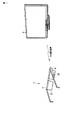
図1に示すように、画像表示システムは、アクティブシャッタ方式の液晶シャッタ1と、表示装置としての液晶表示装置2と、を備えている。
Hereinafter, an image display system including a liquid crystal shutter and a method for driving the liquid crystal shutter according to an embodiment of the present invention will be described in detail with reference to the drawings. First, the configuration of the image display system will be described.
As shown in FIG. 1, the image display system includes an active shutter type
図1乃至図3に示すように、液晶シャッタ1は、第1液晶パネル3Lと、第2液晶パネル3Rと、メガネフレーム4と、駆動部5と、電源部6と、受信器7と、筐体8とを備えている。この実施の形態において、液晶シャッタ1は、メガネ装着型の液晶シャッタである。
As shown in FIGS. 1 to 3, the
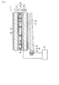
第1液晶パネル3Lは、一対の電極基板10、20と、電極基板間に挟持された液晶層30と、を有している。
電極基板10は、透明な絶縁基板としてのガラス基板11と、このガラス基板11上に形成された第1電極12と、ガラス基板11及び第1電極12上に形成された配向膜13とを有している。絶縁基板としてはガラス基板の他に、プラスチック基板や樹脂フィルムなども適用することができる。電極基板10上には、光学補償フィルム14及び偏光板15が配置されている。光学補償フィルム14及び偏光板15は、ガラス基板11に対して第1電極12の反対側に位置し、ガラス基板11の外面上に順に配置されている。
The first
The
電極基板20は、透明な絶縁基板としてのガラス基板21と、このガラス基板21上に形成された第2電極22と、ガラス基板21及び第2電極22上に形成された配向膜23とを有している。同様に、絶縁基板としてはガラス基板の他に、プラスチック基板や樹脂フィルムなども適用することができる。電極基板20上には、光学補償フィルム24及び偏光板25が配置されている。光学補償フィルム24及び偏光板25は、ガラス基板21に対して第2電極22の反対側に位置し、ガラス基板21の外面上に順に配置されている。
The
第1電極12及び第2電極22は、透明な導電材料として、例えばITO(インジウム・ティン・オキサイド)で形成されている。配向膜13及び配向膜23は、同一方向に配向処理(ラビング)が施されている。偏光板15及び偏光板25は、配向方向に対して略45°で交差するようにクロスニコル配置されている。
The
電極基板10及び電極基板20は、複数のスペーサとしての複数の球状スペーサ31により、所定の隙間を保持して対向配置され、両基板の周縁部に配置されたシール材32により互いに接合されている。球状スペーサ31に代えて柱状スペーサを一方の基板上に一体的に形成することもできる。液晶層30は、電極基板10、電極基板20及びシール材32で囲まれた領域に充填されたネマティック液晶で形成されている。
The
上記のように、第1液晶パネル3Lは、πセルに光学補償フィルム14、24を組合せたOCB(optically compensated bend)モードの液晶パネルである。ここで、第1液晶パネル3Lは、電圧を印加しない状態で光透過状態となるノーマリーホワイト型である。第1液晶パネル3Lは、左目の視界を覆い、左目に入射される光を透過する透過状態(ON)及び左目に入射される光を遮蔽する非透過状態(OFF)に切替え可能である。
As described above, the first
第1電極12に電圧Vdが印加され、第2電極22に電圧Vcomが印加されることにより、液晶層30に駆動電圧が印加される。図4及び図5に示すように、液晶層30に例えば20V程度の閾値電圧以上の駆動電圧が印加されることにより、液晶分子30mがスプレイ(splay)配向からベンド(bend)配向に転移する(初期転移)。そして、液晶層30に所望の駆動電圧が印加されることにより、液晶分子30mのベンド配向を維持しつつ第1液晶パネル3Lを透過状態及び非透過状態に切替えることができる。第1液晶パネル3Lは、ベンド配向とフロー効果により高速応答性に優れている。
When the voltage Vd is applied to the
図1乃至図3に示すように、第2液晶パネル3Rは、上記第1液晶パネル3Lと同様に形成されている。第2液晶パネル3Rは、一対の電極基板10、20及びこれら電極基板間に挟持された液晶層30を有し、右目の視界を覆い、右目に入射される光を透過する透過状態(ON)及び右目に入射される光を遮蔽する非透過状態(OFF)に切替え可能なOCBモードの液晶パネルである。ここで、第2液晶パネル3Rは、電圧を印加しない状態で光透過状態となるノーマリーホワイト型である。
As shown in FIGS. 1 to 3, the second
なお、第1液晶パネル3L及び第2液晶パネル3Rにおいて、図示しないが、これらの形状やこれらに形成される端子の位置は互いに異なっていてもよく、これにより、例えば、第1液晶パネル3L及び第2液晶パネル3Rが左目用及び右目用の何れであるのか識別することができる。
図1に示すように、第1液晶パネル3L及び第2液晶パネル3Rは、メガネフレーム4に取付けられている。
In the first
As shown in FIG. 1, the first
図2に示すように、駆動部5は、フレキシブル配線基板(FPC)等を介して第1液晶パネル3L及び第2液晶パネル3Rそれぞれの第1電極12及び第2電極22に電気的に接続されている。駆動部5は、第1液晶パネル3L及び第2液晶パネル3Rそれぞれに電圧Vd及び電圧Vcomを印加し、第1液晶パネル3L(液晶層30)及び第2液晶パネル3R(液晶層30)に駆動電圧を印加し、それぞれ第1液晶パネル3L及び第2液晶パネル3Rを液晶分子30mがベンド配向を採った状態で透過状態及び非透過状態に交互に切替える。駆動部5は、一透過状態の期間内に、電圧Vdの極性を電圧Vcomに対して少なくとも1回反転させる極性反転駆動を行うものである。
As shown in FIG. 2, the
電源部6及び受信器7は、駆動部5に接続されている。電源部6は、駆動部5に電力を供給するものである。受信器7は、有線又は無線通信によりデータ(同期信号)を受信するものである。駆動部5は、受信器7で受信したデータに基づいて、第1液晶パネル3L及び第2液晶パネル3Rに駆動電圧を印加するものである。筐体8は、駆動部5、電源部6及び受信器7を収容し、メガネフレーム4に取付けられている。
上記のように液晶シャッタ1が形成されている。
The power supply unit 6 and the
As described above, the
図1及び図6に示すように、液晶表示装置2は、液晶表示パネル50、バックライトユニット90、及び制御部100を備えている。液晶表示パネル50は、アレイ基板60と、アレイ基板60に対向配置された対向基板70と、アレイ基板60及び対向基板70間に挟持された液晶層80とを備えている。
As shown in FIGS. 1 and 6, the liquid
図6及び図7に示すように、アレイ基板60は、透明な絶縁基板として矩形状のガラス基板61を備えている。ガラス基板61上には、複数の信号線62と、複数の走査線63とが形成されている。信号線62及び走査線63は、互いに直交して形成されている。また、ガラス基板61上には、走査線63に平行な複数の補助容量線64が形成されている。この実施の形態において、隣合う2本の信号線62及び隣合う2本の走査線63で囲まれた各領域には画素PXが形成されている。これらの画素PXは、ガラス基板61上にマトリクス状に配置されている。
As shown in FIGS. 6 and 7, the
次に、画素PXを1つ取り出して詳述する。
画素PXは、信号線62及び走査線63の交差部近傍に形成されたスイッチング素子としてのTFT(薄膜トランジスタ)65と、TFT65に接続された画素電極66と、画素電極66に接続された補助容量素子67と、を有している。補助容量線64は、補助容量素子67の一方の電極を形成している。
Next, one pixel PX is taken out and described in detail.
The pixel PX includes a TFT (thin film transistor) 65 as a switching element formed in the vicinity of the intersection of the
図示しないが、ガラス基板61上に、赤色、緑色及び青色の複数の着色層を有したカラーフィルタが形成されている。なお、上記画素電極66はITO等の透明な導電材料でカラーフィルタ上に形成されている。また、カラーフィルタ上には、スペーサとして、例えば複数の柱状スペーサ68が形成されている。上記のように、ガラス基板61上にアレイパターン60Pが形成されている。ガラス基板61及びアレイパターン60P上に配向膜69が形成されている。
Although not shown, a color filter having a plurality of colored layers of red, green, and blue is formed on the
対向基板70は、透明な絶縁基板として矩形状のガラス基板71を備えている。ガラス基板71上に、対向電極72及び配向膜73が順に形成されている。なお、配向膜69及び配向膜73には同一方向に配向処理(ラビング)が施されている。このように、対向基板70が形成されている。
The
アレイ基板60及び対向基板70間の隙間は、複数の柱状スペーサ68により保持されている。アレイ基板60及び対向基板70は、表示領域の外周に沿って配置されたシール材81により接合されている。液晶層80は、アレイ基板60、対向基板70及びシール材81で囲まれた領域に充填されたネマティック液晶で形成されている。
A gap between the
アレイ基板60の外面上に、光学補償フィルム51及び偏光板52が順に形成されている。対向基板70の外面上に、光学補償フィルム53及び偏光板54が順に形成されている。偏光板52及び偏光板54は、配向方向に対して略45°で交差するようにクロスニコル配置されている。上記のように、液晶表示パネル50は、OCBモードの液晶パネルである。ここで、液晶表示パネル50は、電圧を印加しない状態で光透過状態となるノーマリーホワイト型である。
An
図6に示すように、バックライトユニット90は、アレイ基板60の外面側に設けられている。バックライトユニット90は、偏光板52と対向した導光板を含む導光体92と、導光体92の一側縁に対向配置された、例えば冷陰極線管からなる光源93及び反射板94を有している。
As shown in FIG. 6, the backlight unit 90 is provided on the outer surface side of the
次に、画像表示システムを用いて立体画像を表示する場合の上記液晶シャッタ1及び液晶表示装置2の動作について説明する。
図6及び図8に示すように、制御部100は、立体画像を表示する場合、例えば120Hzのフレーム周波数で左目用の画像と右目用の画像とを交互に表示するよう、液晶表示パネル50の駆動を制御する。ここで、1フレーム(1F)とは、全ての画素PXを順次走査し再び同一の画素PXを走査するまでの時間である。
Next, operations of the
As shown in FIGS. 6 and 8, when displaying a stereoscopic image, the
上記のことから、液晶表示装置2は、実質60Hzの周波数で解像度の低下なく立体画像の表示を可能にしている。
From the above, the liquid
図1、図2及び図8に示すように、任意の1フレームの期間、駆動部5は、液晶表示装置2による右目用の画像表示に同期を取って第1液晶パネル3Lを非透過状態(OFF)に切替えている間、第2液晶パネル3Rを透過状態(ON)に切替える。このフレームの期間、第1液晶パネル3Lの透過率はほぼ0%である。
As shown in FIGS. 1, 2, and 8, the
続く、1フレームの期間、駆動部5は、液晶表示装置2による左目用の画像表示に同期を取って第1液晶パネル3Lを透過状態(ON)に切替えている間、第2液晶パネル3Rを非透過状態(OFF)に切替える。第1液晶パネル3Lを透過状態(ON)に切替えると、第1液晶パネル3Lは高速応答性を示し、第1液晶パネル3Lの透過率が0%から上昇する。このため、このフレームの期間、第1液晶パネル3Lは透過状態となる。
Subsequently, during the period of one frame, the driving
その後も、液晶表示装置2の画像表示に同期を取って第1液晶パネル3L及び第2液晶パネル3Rを交互に透過状態に切替える。駆動部5は、それぞれ第1液晶パネル3L及び第2液晶パネル3Rを透過状態(ON)に切替える際、前回、透過状態(ON)に切替えてから60分の1秒後に切替えている。これにより、液晶シャッタ1を装着したユーザは、左目用の画像と、右目用の画像とを左右の目で交互にみることができ、ユーザに立体画像を表示することができる。
Thereafter, the first
次に、上記画像表示システムの実施例1乃至5の画像表示システムの液晶シャッタ1及び液晶シャッタ1の駆動方法について説明する。実施例1乃至5の液晶シャッタ1及び液晶シャッタ1の駆動方法は、フリッカの発生を抑制できる液晶シャッタ及び液晶シャッタの駆動方法の例である。
Next, the
(実施例1)
まず、実施例1の液晶シャッタ1及び液晶シャッタ1の駆動方法について説明する。
図2、図3及び図8に示すように、第1液晶パネル3Lが非透過状態(OFF)となる1フレーム期間、駆動部5は、第1液晶パネル3Lの第1電極12に前半−10V、後半+10Vの電圧Vdを印加し、第2電極22に0Vの電圧Vcomを印加する。なお、第2電極22は、例えば接地電位に設定される。
Example 1
First, the
As shown in FIGS. 2, 3, and 8, during one frame period in which the first liquid crystal panel 3 </ b> L is in a non-transmissive state (OFF), the driving
上記のように、第1液晶パネル3Lが非透過状態(OFF)となる1フレーム期間、駆動部5は、第1液晶パネル3L(第1電極12)に印加する電圧Vdの極性を1回反転させる極性反転駆動を行う。
As described above, the driving
次いで、上記1フレーム期間に続き、第1液晶パネル3Lが透過状態(ON)となる1フレーム期間、駆動部5は、第1液晶パネル3Lの第1電極12に前半−4V、後半+4Vの電圧Vdを印加する。
Next, following the one frame period, during the one frame period in which the first
上記のように、第1液晶パネル3Lが透過状態(ON)となる1フレーム期間、駆動部5は、第1液晶パネル3Lに印加する電圧Vdの極性を1回反転させる極性反転駆動を行う。第1液晶パネル3Lを透過状態(ON)とする駆動電圧は、第1液晶パネル3Lを非透過状態(OFF)とする駆動電圧より小さい。
As described above, during one frame period in which the first
その後も同様に、第1液晶パネル3Lは、1フレーム期間毎に非透過状態(OFF)及び透過状態(ON)に交互に切替えられる。
第2液晶パネル3Rも第1液晶パネル3Lと同様に駆動され、極性反転駆動しつつ、1フレーム期間毎に透過状態(ON)及び非透過状態(OFF)に交互に切替えられる。
Similarly, the first
The second
(実施例2)
次に、実施例2の液晶シャッタ1及び液晶シャッタ1の駆動方法について説明する。実施例2の液晶シャッタ1及び液晶シャッタ1の駆動方法は、非透過状態(OFF)の期間、第1液晶パネル3L及び第2液晶パネル3Rを極性反転駆動しない以外、上記実施例1の液晶シャッタ1及び液晶シャッタ1の駆動方法と同様に構成されている。
(Example 2)
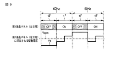
Next, the
詳しくは、図2、図3及び図9に示すように、第1液晶パネル3Lが非透過状態(OFF)となる1フレーム期間、駆動部5は、第1液晶パネル3Lの第1電極12に−10Vの電圧Vdを印加し、第2電極22に0Vの電圧Vcomを印加する。なお、第2電極22は、常時、接地電位に設定される。
Specifically, as shown in FIGS. 2, 3, and 9, during one frame period in which the first liquid crystal panel 3 </ b> L is in a non-transmissive state (OFF), the driving
上記のように、第1液晶パネル3Lが非透過状態(OFF)となる1フレーム期間、駆動部5は、極性反転駆動無しに、第1液晶パネル3L(第1電極12)に電圧Vdを印加する。
As described above, the driving
次いで、上記1フレーム期間に続き、第1液晶パネル3Lが透過状態(ON)となる1フレーム期間、駆動部5は、第1液晶パネル3Lの第1電極12に前半−4V、後半+4Vの電圧Vdを印加する。
Next, following the one frame period, during the one frame period in which the first
上記のように、第1液晶パネル3Lが透過状態(ON)となる1フレーム期間、駆動部5は、第1液晶パネル3L(第1電極12)に印加する電圧Vdの極性を1回反転させる極性反転駆動を行う。
As described above, the driving
次いで、上記1フレーム期間に続き、第1液晶パネル3Lが再び非透過状態(OFF)となる1フレーム期間、駆動部5は、第1液晶パネル3Lの第1電極12に+10Vの電圧Vdを印加する。第1液晶パネル3Lを透過状態(ON)とする駆動電圧は、第1液晶パネル3Lを非透過状態(OFF)とする駆動電圧より小さい。
Next, following the one frame period, the driving
その後も同様に、第1液晶パネル3Lは、1フレーム期間毎に透過状態(ON)及び非透過状態(OFF)に交互に切替えられる。
第2液晶パネル3Rも第1液晶パネル3Lと同様に駆動され、透過状態(ON)の期間毎に極性反転駆動しつつ、1フレーム期間毎に透過状態(ON)及び非透過状態(OFF)に交互に切替えられる。
Similarly thereafter, the first
The second
(実施例3)
次に、実施例3の液晶シャッタ1及び液晶シャッタ1の駆動方法について説明する。実施例3の液晶シャッタ1及び液晶シャッタ1の駆動方法は、透過状態(ON)及び非透過状態(OFF)の各期間、第1液晶パネル3L及び第2液晶パネル3Rを電圧Vdの極性を3回反転させて極性反転駆動する以外、上記実施例1の液晶シャッタ1及び液晶シャッタ1の駆動方法と同様に構成されている。
(Example 3)
Next, the
詳しくは、図2、図3及び図10に示すように、第1液晶パネル3Lが非透過状態(OFF)となる1フレーム期間、駆動部5は、第1液晶パネル3Lの第1電極12に−10V、+10Vの電圧Vdを交互に印加し、第2電極22に0Vの電圧Vcomを印加する。なお、第2電極22は、常時、接地電位に設定される。
Specifically, as shown in FIGS. 2, 3, and 10, during one frame period in which the first liquid crystal panel 3 </ b> L is in a non-transmissive state (OFF), the driving
上記のように、第1液晶パネル3Lが非透過状態(OFF)となる1フレーム期間、駆動部5は、第1液晶パネル3L(第1電極12)に印加する電圧Vdの極性を3回反転させる極性反転駆動を行う。
As described above, the
次いで、上記1フレーム期間に続き、第1液晶パネル3Lが透過状態(ON)となる1フレーム期間、駆動部5は、第1液晶パネル3Lの第1電極12に−4V、+4Vの電圧Vdを交互に印加する。
Next, following the one frame period, in one frame period in which the first
上記のように、第1液晶パネル3Lが透過状態(ON)となる1フレーム期間、駆動部5は、第1液晶パネル3Lに印加する電圧Vdの極性を3回反転させる極性反転駆動を行う。第1液晶パネル3Lを透過状態(ON)とする駆動電圧は、第1液晶パネル3Lを非透過状態(OFF)とする駆動電圧より小さい。
As described above, during one frame period in which the first
その後も同様に、第1液晶パネル3Lは、1フレーム期間毎に非透過状態(OFF)及び透過状態(ON)に交互に切替えられる。
第2液晶パネル3Rも第1液晶パネル3Lと同様に駆動され、極性反転駆動しつつ、1フレーム期間毎に透過状態(ON)及び非透過状態(OFF)に交互に切替えられる。
Similarly, the first
The second
(実施例4)
次に、実施例4の液晶シャッタ1及び液晶シャッタ1の駆動方法について説明する。実施例4の液晶シャッタ1及び液晶シャッタ1の駆動方法は、電圧Vdの振幅を小さくし、電圧Vcomを定電圧からパルス電圧に変えた以外、上記実施例1の液晶シャッタ1及び液晶シャッタ1の駆動方法と同様に構成されている。
Example 4
Next, the
詳しくは、図2、図3及び図11に示すように、第1液晶パネル3Lが非透過状態(OFF)となる1フレーム期間、駆動部5は、第1液晶パネル3Lの第1電極12に前半−5V、後半+5Vの電圧Vdを印加し、第2電極22に前半+5V、後半−5Vの電圧Vcomを印加する。
Specifically, as shown in FIGS. 2, 3, and 11, during one frame period in which the first liquid crystal panel 3 </ b> L is in a non-transmissive state (OFF), the driving
上記のように、第1液晶パネル3Lが非透過状態(OFF)となる1フレーム期間、駆動部5は、第1液晶パネル3Lに印加する電圧Vd及び電圧Vcomの極性をそれぞれ1回反転させる極性反転駆動を行う。
As described above, during one frame period in which the first
次いで、上記1フレーム期間に続き、第1液晶パネル3Lが透過状態(ON)となる1フレーム期間、駆動部5は、第1液晶パネル3Lの第1電極12に前半−2V、後半+2Vの電圧Vdを印加し、第2電極22に前半+2V、後半−2Vの電圧Vcomを印加する。
Next, following the one frame period, in one frame period in which the first
上記のように、第1液晶パネル3Lが透過状態(ON)となる1フレーム期間、駆動部5は、第1液晶パネル3Lに印加する電圧Vd及び電圧Vcomの極性をそれぞれ1回反転させる極性反転駆動を行う。第1液晶パネル3Lを透過状態(ON)とする駆動電圧は、第1液晶パネル3Lを非透過状態(OFF)とする駆動電圧より小さい。
As described above, during one frame period when the first
その後も同様に、第1液晶パネル3Lは、1フレーム期間毎に非透過状態(OFF)及び透過状態(ON)に交互に切替えられる。
第2液晶パネル3Rも第1液晶パネル3Lと同様に駆動され、極性反転駆動しつつ、1フレーム期間毎に透過状態(ON)及び非透過状態(OFF)に交互に切替えられる。
Similarly, the first
The second
(実施例5)
次に、実施例5の液晶シャッタ1及び液晶シャッタ1の駆動方法について説明する。実施例5の液晶シャッタ1及び液晶シャッタ1の駆動方法は、電圧Vdの振幅を小さくし、電圧Vcomを定電圧からパルス電圧に変えた以外、上記実施例2の液晶シャッタ1及び液晶シャッタ1の駆動方法と同様に構成されている。
(Example 5)
Next, the
詳しくは、図2、図3及び図12に示すように、第1液晶パネル3Lが非透過状態(OFF)となる1フレーム期間、駆動部5は、第1液晶パネル3Lの第1電極12に−5Vの電圧Vdを印加し、第2電極22に+5Vの電圧Vcomを印加する。
Specifically, as shown in FIGS. 2, 3, and 12, during one frame period in which the first liquid crystal panel 3 </ b> L is in a non-transmissive state (OFF), the driving
上記のように、第1液晶パネル3Lが非透過状態(OFF)となる1フレーム期間、駆動部5は、極性反転駆動無しに、第1液晶パネル3Lに電圧Vd及び電圧Vcomを印加する。
As described above, the driving
次いで、上記1フレーム期間に続き、第1液晶パネル3Lが透過状態(ON)となる1フレーム期間、駆動部5は、第1液晶パネル3Lの第1電極12に前半−2V、後半+2Vの電圧Vdを印加し、第2電極22に前半+2V、後半−2Vの電圧Vcomを印加する。
Next, following the one frame period, in one frame period in which the first
上記のように、第1液晶パネル3Lが透過状態(ON)となる1フレーム期間、駆動部5は、第1液晶パネル3Lに印加する電圧Vd及び電圧Vcomの極性をそれぞれ1回反転させる極性反転駆動を行う。第1液晶パネル3Lを透過状態(ON)とする駆動電圧は、第1液晶パネル3Lを非透過状態(OFF)とする駆動電圧より小さい。
As described above, during one frame period when the first
その後も同様に、第1液晶パネル3Lは、1フレーム期間毎に非透過状態(OFF)及び透過状態(ON)に交互に切替えられる。
第2液晶パネル3Rも第1液晶パネル3Lと同様に駆動され、透過状態(ON)の期間毎に極性反転駆動しつつ、1フレーム期間毎に透過状態(ON)及び非透過状態(OFF)に交互に切替えられる。
Similarly, the first
The second
次に、上記実施の形態の画像表示システムの液晶シャッタ1及び液晶表示装置2の関係をさらに説明する。以下、液晶シャッタ1は、実施例1の液晶シャッタ1を例に説明する。液晶表示装置2は、映像(動画像)及び静止画像を表示可能であるが、ここでは、液晶表示装置2が映像を表示する場合について説明する。
Next, the relationship between the
図1に示すように、液晶表示装置2は、映像を表示し、現在表示されている映像が左目用映像及び右目用映像のどちらであるかを示す識別情報を同時に出力する。図1及び図2に示すように、液晶シャッタ1の受信器7は、液晶表示装置2から出力される識別情報を受信し、この情報を駆動部5に伝送する。これにより、駆動部5は、第1液晶パネル3L及び第2液晶パネル3Rの開閉動作を、液晶表示装置2の左目用の映像表示及び右目用の映像表示に同期させることができる。
As shown in FIG. 1, the liquid
図13には、液晶表示装置2の構成を示している。
図13に示すように、液晶表示装置2の入力端子110には、左目用の映像信号及び右目用の映像信号が入力される。これらの信号は、放送信号から取得した信号、及び記録媒体から再生された信号の何れであってもよい。入力端子110には、平面映像表示用の映像信号も入力されるが、以下、立体映像表示用の映像信号(左目用の映像信号及び右目用の映像信号)が入力される場合について説明する。
FIG. 13 shows the configuration of the liquid
As shown in FIG. 13, the video signal for the left eye and the video signal for the right eye are input to the
入力端子110に入力された映像信号は映像信号処理回路111及び同期信号処理回路113に伝送される。同期信号処理回路113は、映像信号から水平同期信号H及び垂直同期信号Vを分離して出力する。
The video signal input to the
水平同期信号H及び垂直同期信号Vは、映像信号処理回路111に入力され、信号処理のためのタイミングパルスとして利用される。また、水平同期信号H及び垂直同期信号Vは、液晶表示装置2の表示部112に入力され、水平走査、垂直走査のためのタイミングパルスとして利用される。液晶表示装置2は、映像信号処理回路111から出力される左目用映像信号L及び右目用映像信号Rを交互に表示する。
The horizontal synchronization signal H and the vertical synchronization signal V are input to the video
ここで、右目用映像信号Rの一部には、例えば、垂直ブランキング期間の直後であって、通常は表示領域には現れない水平期間にR識別信号RIDが挿入されている。R識別信号RIDは、映像信号処理回路111にて抽出される。このR識別信号RIDは、同期信号送信回路114に入力される。また、同期信号送信回路114には、上記垂直同期信号Vも入力される。
Here, in part of the right-eye video signal R, for example, an R identification signal RID is inserted in a horizontal period that is immediately after a vertical blanking period and does not normally appear in the display area. The R identification signal RID is extracted by the video
同期信号送信回路114は、垂直同期信号V及びR識別信号RIDを用いて、第2液晶パネル同期信号RG_SYNCを生成し、受信器7に向けて送信する。この実施例では、第2液晶パネル同期信号RG_SYNCを送信しているが、第1液晶パネル同期信号であってもよく、また両方を送信しても良い。
The synchronization
図14には、液晶シャッタ1の受信器7を示している。また、図15には、受信器7の各部の信号波形を示している。
図14及び図15に示すように、受信回路211は、第2液晶パネル同期信号RG_SYNCを復調する。第2液晶パネル同期信号RG_SYNCは、電圧制御発振器212に位相同期信号aとして入力される。電圧制御発振器212は、位相ロックループ及び分周器を含むものであり、第2液晶パネル同期信号RG_SYNCに位相同期したパルス信号bを生成し、出力する。パルス信号bは、1フレーム期間毎に、ローレベルからハイレベルに切替えられる。パルス信号bは、増幅器213に入力され基準電位を中心にして正、負対称のパルスに整形され、スイッチ215に入力される。また、パルス信号bは1/2分周器214に入力され、1/2分周器214はスイッチ制御パルス信号cとして出力する。
FIG. 14 shows the
As shown in FIGS. 14 and 15, the receiving
スイッチ制御パルスcが正のとき、スイッチ215を端子Aに接続し、スイッチ制御パルスcが負のとき、スイッチ215を端子Bに接続する。端子Aは、増幅器216及び増幅器219に接続され、端子Bは増幅器217及び増幅器218に接続されている。増幅器216は端子Aからの信号dを増幅し、増幅器217は端子Bからの信号eを増幅する。増幅器216及び増幅器217で増幅された信号は、合成され、出力端子221に第2液晶パネル駆動信号h(電圧Vd)として出力される。ここで、増幅器216の増幅率は増幅器217の増幅率より小さく設定されている。
When the switch control pulse c is positive, the
一方、増幅器219は端子Aからの信号g(=d)を増幅し、増幅器218は端子Bからの信号f(=e)を増幅する。増幅器219及び増幅器218で増幅された信号は、合成され、出力端子222に第1液晶パネル駆動信号i(電圧Vd)として出力される。ここで、増幅器218の増幅率は増幅器219の増幅率より小さく設定されている。
On the other hand, the amplifier 219 amplifies the signal g (= d) from the terminal A, and the
上記第2液晶パネル駆動信号h及び第1液晶パネル駆動信号iにより、第2液晶パネル3R及び第1液晶パネル3Lがそれぞれ駆動される。なお、図15のjには、第1液晶パネル3L(左目用)及び第2液晶パネル3R(右目用)の開閉シーケンスを示し、kには、液晶表示装置に表示される左目用の映像及び右目用の映像のシーケンスを示している。
The second
以上のように構成された液晶シャッタ1を備えた画像表示システム及び液晶シャッタ1の駆動方法によれば、画像表示システムは、メガネ装着型の液晶シャッタ1と、左目用の画像(映像)と右目用の画像(映像)とを交互に表示する液晶表示装置2とを備えている。液晶シャッタ1は、左目用のOCBモードの第1液晶パネル3Lと、右目用のOCBモードの第2液晶パネル3Rと、駆動部5とを備えている。
According to the image display system including the
駆動部5は、第1液晶パネル3L及び第2液晶パネル3Rに電圧を印加し、それぞれ第1液晶パネル3L及び第2液晶パネル3Rを透過状態(ON)及び非透過状態(OFF)に交互に切替えている。第1液晶パネル3L及び第2液晶パネル3Rそれぞれの非透過状態(OFF)において、黒表示(黒挿入)により、液晶分子30mのベンド配向状態を維持することができ、すなわち液晶分子30mのベンド配向からスプレイ配向への逆転移を抑制でき、かつ、鮮明な画像表示に寄与することができる。
The driving
液晶表示装置2は120Hzの周波数で左目用の画像(映像)と右目用の画像(映像)とを交互に表示し、第1液晶パネル3L及び第2液晶パネル3Rは120Hzの周波数で透過状態(ON)及び非透過状態(OFF)に交互に切替えられるため、実質60Hzの周波数で画像を表示した場合と同等の鮮明な立体画像を液晶シャッタ1を装着したユーザに表示することができる。
The liquid
駆動部5は、一透過状態(ON)の期間内に実施例1乃至3では電圧Vdの極性を、実施例4及び5では電圧Vd及びVcomの極性を、少なくとも1回反転させる極性反転駆動を行っている。第1液晶パネル3L及び第2液晶パネル3Rそれぞれの第1電極12及び第2電極22間に印加される電圧の極性を、2フレーム期間(60分の1秒間)で少なくとも1回反転させているため、第1液晶パネル3L及び第2液晶パネル3Rに生じる恐れのあるフリッカの発生を抑制することができ、フレーム周波数を高くした場合と同様の効果を得ることができる。
そして、第1液晶パネル3L及び第2液晶パネル3Rそれぞれの電圧−透過率特性に拘ること無しに、フリッカの発生を抑制することができる。
The
The occurrence of flicker can be suppressed without being concerned with the voltage-transmittance characteristics of the first
実施例2及び5では、透過状態(ON)の期間のみ極性反転駆動を行っているため、消費電力の上昇を抑制することができる。
また、実施例1、3及び4では、透過状態(ON)の期間だけでなく非透過状態(OFF)の期間毎にも極性反転駆動を行っている。これにより、黒表示時に生じる恐れのあるフリッカの発生を抑制することができる。
In the second and fifth embodiments, the polarity inversion driving is performed only in the transmission state (ON) period, and thus an increase in power consumption can be suppressed.
In the first, third, and fourth embodiments, the polarity inversion driving is performed not only in the transmission state (ON) period but also in the non-transmission state (OFF) period. Thereby, it is possible to suppress the occurrence of flicker that may occur during black display.
上記したことから、フリッカの発生を抑制できる液晶シャッタ1、液晶シャッタ1の駆動方法及び液晶シャッタ1を備えた画像表示システムを得ることができる。
As described above, it is possible to obtain the
なお、この発明は上記実施の形態そのままに限定されるものではなく、実施段階ではその要旨を逸脱しない範囲で構成要素を変形して具体化可能である。また、上記実施の形態に開示されている複数の構成要素の適宜な組み合わせにより、種々の発明を形成できる。例えば、実施形態に示される全構成要素から幾つかの構成要素を削除してもよい。さらに、異なる実施例にわたる構成要素を適宜組み合わせてもよい。 Note that the present invention is not limited to the above-described embodiment as it is, and can be embodied by modifying the constituent elements without departing from the scope of the invention in the implementation stage. Various inventions can be formed by appropriately combining a plurality of constituent elements disclosed in the embodiments. For example, some components may be deleted from all the components shown in the embodiment. Furthermore, constituent elements over different embodiments may be appropriately combined.
例えば、駆動部5は、透過状態(ON)の期間毎に電圧の極性を少なくとも1回反転させる極性反転駆動を行えばよく、1回及び3回に限らず、2回又は4回以上極性を反転させても上述した効果を得ることができる。
For example, the driving
上記電圧Vd及び電圧Vcomの電圧値は上記の例に限定されるものではなく、種々変形可能であり、第1液晶パネル3L及び第2液晶パネル3Rの設計に合うよう調整されていればよい。
The voltage values of the voltage Vd and the voltage Vcom are not limited to the above examples, and can be variously modified and may be adjusted to suit the design of the first
上記実施の形態において、液晶表示装置2は120Hzの周波数で左目用の画像(映像)と右目用の画像(映像)とを交互に表示し、第1液晶パネル3L及び第2液晶パネル3Rは120Hzの周波数で透過状態(ON)及び非透過状態(OFF)に交互に切替えられるが、これらの周波数は120Hzに限定されるものではなく、より高い周波数、例えば240Hzで駆動するなど、種々変形可能である。
In the above embodiment, the liquid
第1液晶パネル3L及び第2液晶パネル3Rは、ノーマリーホワイト型であるが、これに限定されるものではなく、設計を調整することにより、電圧を印加しない状態で光遮断状態となるノーマリーブラック型であってもよい。
The first
駆動部5は、筐体8に収容されているが、これに限定されるものではなく種々変形可能であり、例えば、一部又は全てが第1液晶パネル3L及び第2液晶パネル3Rに設けられていてもよい。
The
液晶シャッタ1は、メガネ装着型の液晶シャッタに限定されるものではなく、種々変形可能であり、この場合、メガネフレーム4以外の部材に取付けられていればよい。
The
液晶シャッタ1の用途は、立体画像表示用に限定されるものではなく、種々変形可能であり、例えば、コンテンツ選択用であってもよい。この場合、液晶表示装置2に第1コンテンツの画像及び第2コンテンツの画像を交互に表示し、液晶シャッタ1を装着したユーザに、選択した一方のコンテンツの画像のみ表示することができる。
The use of the
詳しくは、駆動部5は、液晶表示装置2による第1コンテンツの画像表示及び第2コンテンツの画像表示の一方に同期を取って第1液晶パネル3L及び第2液晶パネル3Rを透過状態(ON)に切替え、第1コンテンツの画像表示及び第2コンテンツの画像表示の他方に同期を取って第1液晶パネル3L及び第2液晶パネル3Rを非透過状態(OFF)に切替える。これにより、第1コンテンツ及び第2コンテンツの一方の画像を液晶シャッタ1を装着したユーザに表示することができる。
Specifically, the driving
上記表示装置は、液晶表示装置2に限定されるものではなく、種々変形可能であり、PDP(Plasma Display Panel)やCRT(cathode-ray tube)表示装置等の表示装置であってもよい。
The display device is not limited to the liquid
1…液晶シャッタ、2…液晶表示装置、3L…第1液晶パネル、3R…第2液晶パネル、4…メガネフレーム、5…駆動部、7…受信器、10,20…電極基板、14,24…光学補償フィルム、15,25…偏光板、30…液晶層、30m…液晶分子、50…液晶表示パネル、90…バックライトユニット、100…制御部、PX…画素、Vd,Vcom…電圧。
DESCRIPTION OF
Claims (11)
一対の電極基板及び前記電極基板間に挟持された液晶層を有し、右目の視界を覆い、右目に入射される光を透過する透過状態及び右目に入射される光を遮蔽する非透過状態に切替え可能なOCBモードの第2液晶パネルと、
前記第1液晶パネル及び第2液晶パネルに電圧を印加し、それぞれ前記第1液晶パネル及び第2液晶パネルを前記透過状態及び非透過状態に交互に切替えると共に、一前記透過状態の期間内に前記一対の電極基板間に印加される電圧の極性を少なくとも1回反転させる極性反転駆動を行う駆動部と、を備えていることを特徴とする液晶シャッタ。 It has a pair of electrode substrates and a liquid crystal layer sandwiched between the electrode substrates, covers the field of view of the left eye, and is in a transmissive state that transmits light incident on the left eye and a non-transmissive state that blocks light incident on the left eye A switchable OCB mode first liquid crystal panel;
A pair of electrode substrates and a liquid crystal layer sandwiched between the electrode substrates, covering the field of view of the right eye, in a transmissive state that transmits light incident on the right eye and in a non-transmissive state that blocks light incident on the right eye A switchable OCB mode second liquid crystal panel;
A voltage is applied to the first liquid crystal panel and the second liquid crystal panel, and the first liquid crystal panel and the second liquid crystal panel are alternately switched between the transmission state and the non-transmission state, respectively, and within one period of the transmission state A liquid crystal shutter, comprising: a drive unit that performs polarity inversion driving that inverts the polarity of a voltage applied between the pair of electrode substrates at least once.
前記第1液晶パネル及び第2液晶パネルは、前記メガネフレームに取付けられていることを特徴とする請求項1乃至4の何れか1項に記載の液晶シャッタ。 A glasses frame,
5. The liquid crystal shutter according to claim 1, wherein the first liquid crystal panel and the second liquid crystal panel are attached to the glasses frame.
前記第1液晶パネル及び第2液晶パネルに電圧を印加し、それぞれ前記第1液晶パネル及び第2液晶パネルを前記透過状態及び非透過状態に交互に切替え、
一前記透過状態の期間内に前記一対の電極基板間に印加される電圧の極性を少なくとも1回反転させる極性反転駆動を行うことを特徴とする液晶シャッタの駆動方法。 It has a pair of electrode substrates and a liquid crystal layer sandwiched between the electrode substrates, covers the field of view of the left eye, and is in a transmissive state that transmits light incident on the left eye and a non-transmissive state that blocks light incident on the left eye A switchable OCB mode first liquid crystal panel, a pair of electrode substrates and a liquid crystal layer sandwiched between the electrode substrates, covering the right eye field of view and transmitting light incident on the right eye and the right eye A liquid crystal shutter driving method comprising: an OCB mode second liquid crystal panel that can be switched to a non-transmissive state that shields light incident on the liquid crystal;
A voltage is applied to the first liquid crystal panel and the second liquid crystal panel, and the first liquid crystal panel and the second liquid crystal panel are alternately switched between the transmissive state and the non-transmissive state,
1. A driving method of a liquid crystal shutter, wherein polarity inversion driving is performed to invert the polarity of a voltage applied between the pair of electrode substrates at least once within the period of the transmission state.
左目用の画像と右目用の画像とを交互に表示する表示装置と、を備え、
前記駆動部は、前記左目用の画像表示に同期を取って前記第1液晶パネルを透過状態に切替え前記第2液晶パネルを非透過状態に切替え、前記右目用の画像表示に同期を取って前記第1液晶パネルを非透過状態に切替え前記第2液晶パネルを透過状態に切替え、立体画像を表示することを特徴とする画像表示システム。 It has a pair of electrode substrates and a liquid crystal layer sandwiched between the electrode substrates, covers the field of view of the left eye, and is in a transmissive state that transmits light incident on the left eye and a non-transmissive state that blocks light incident on the left eye A switchable OCB mode first liquid crystal panel, a pair of electrode substrates and a liquid crystal layer sandwiched between the electrode substrates, covering the right eye field of view and transmitting light incident on the right eye and the right eye A voltage is applied to the second liquid crystal panel in the OCB mode that can be switched to a non-transmissive state that shields light incident on the first liquid crystal panel, and the first liquid crystal panel and the second liquid crystal panel, respectively. A drive unit for alternately switching the panel between the transmissive state and the non-transmissive state, and performing polarity reversal driving for reversing the polarity of the voltage applied between the pair of electrode substrates at least once within the period of the transmissive state; And a liquid crystal shutter having a
A display device that alternately displays an image for the left eye and an image for the right eye,
The drive unit synchronizes with the image display for the left eye, switches the first liquid crystal panel to a transmission state, switches the second liquid crystal panel to a non-transmission state, and synchronizes with the image display for the right eye to synchronize with the image display for the right eye. An image display system characterized in that the first liquid crystal panel is switched to a non-transmissive state, the second liquid crystal panel is switched to a transmissive state, and a stereoscopic image is displayed.
第1コンテンツの画像と第2コンテンツの画像とを交互に表示する表示装置と、を備え、
前記駆動部は、前記第1コンテンツの画像表示及び第2コンテンツの画像表示の一方に同期を取って前記第1液晶パネル及び第2液晶パネルを透過状態に切替え、前記第1コンテンツの画像表示及び第2コンテンツの画像表示の他方に同期を取って前記第1液晶パネル及び第2液晶パネルを非透過状態に切替え、前記第1コンテンツ及び第2コンテンツの一方の画像を表示することを特徴とする画像表示システム。 It has a pair of electrode substrates and a liquid crystal layer sandwiched between the electrode substrates, covers the field of view of the left eye, and is in a transmissive state that transmits light incident on the left eye and a non-transmissive state that blocks light incident on the left eye A switchable OCB mode first liquid crystal panel, a pair of electrode substrates and a liquid crystal layer sandwiched between the electrode substrates, covering the right eye field of view and transmitting light incident on the right eye and the right eye A voltage is applied to the second liquid crystal panel in the OCB mode that can be switched to a non-transmissive state that shields light incident on the first liquid crystal panel, and the first liquid crystal panel and the second liquid crystal panel, respectively. A drive unit for alternately switching the panel between the transmissive state and the non-transmissive state, and performing polarity reversal driving for reversing the polarity of the voltage applied between the pair of electrode substrates at least once within the period of the transmissive state; And a liquid crystal shutter having a
A display device that alternately displays an image of the first content and an image of the second content,
The driving unit synchronizes one of the image display of the first content and the image display of the second content and switches the first liquid crystal panel and the second liquid crystal panel to a transmissive state to display the image of the first content and The first liquid crystal panel and the second liquid crystal panel are switched to a non-transparent state in synchronization with the other image display of the second content, and one image of the first content and the second content is displayed. Image display system.
Priority Applications (2)
| Application Number | Priority Date | Filing Date | Title |
|---|---|---|---|
| JP2009282054A JP2011123371A (en) | 2009-12-11 | 2009-12-11 | Liquid crystal shutter, method for driving the same, and image display system |
| US12/965,237 US8570448B2 (en) | 2009-12-11 | 2010-12-10 | Liquid crystal shutter, driving method of the same and image display system |
Applications Claiming Priority (1)
| Application Number | Priority Date | Filing Date | Title |
|---|---|---|---|
| JP2009282054A JP2011123371A (en) | 2009-12-11 | 2009-12-11 | Liquid crystal shutter, method for driving the same, and image display system |
Publications (1)
| Publication Number | Publication Date |
|---|---|
| JP2011123371A true JP2011123371A (en) | 2011-06-23 |
Family
ID=44142526
Family Applications (1)
| Application Number | Title | Priority Date | Filing Date |
|---|---|---|---|
| JP2009282054A Withdrawn JP2011123371A (en) | 2009-12-11 | 2009-12-11 | Liquid crystal shutter, method for driving the same, and image display system |
Country Status (2)
| Country | Link |
|---|---|
| US (1) | US8570448B2 (en) |
| JP (1) | JP2011123371A (en) |
Families Citing this family (3)
| Publication number | Priority date | Publication date | Assignee | Title |
|---|---|---|---|---|
| WO2011065053A1 (en) * | 2009-11-26 | 2011-06-03 | シャープ株式会社 | Light guide plate, light guide unit, lighting device, and display device |
| JP2011215400A (en) * | 2010-03-31 | 2011-10-27 | Toshiba Mobile Display Co Ltd | Liquid crystal shutter, method for driving the same, and image display system |
| KR101981527B1 (en) * | 2012-11-08 | 2019-05-23 | 엘지디스플레이 주식회사 | Autostereoscopic image display and driving method thereof |
Family Cites Families (4)
| Publication number | Priority date | Publication date | Assignee | Title |
|---|---|---|---|---|
| JP3454651B2 (en) | 1996-12-26 | 2003-10-06 | 三洋電機株式会社 | Liquid crystal shutter glasses for stereoscopic video display |
| JP2000275575A (en) | 1999-03-24 | 2000-10-06 | Sharp Corp | Stereoscopic video display device |
| JP4637068B2 (en) | 2005-09-14 | 2011-02-23 | オリンパスビジュアルコミュニケーションズ株式会社 | 3D image display method and 3D image display system |
| CA2684513A1 (en) * | 2008-11-17 | 2010-05-17 | X6D Limited | Improved performance 3d glasses |
-
2009
- 2009-12-11 JP JP2009282054A patent/JP2011123371A/en not_active Withdrawn
-
2010
- 2010-12-10 US US12/965,237 patent/US8570448B2/en active Active
Also Published As
| Publication number | Publication date |
|---|---|
| US8570448B2 (en) | 2013-10-29 |
| US20110141382A1 (en) | 2011-06-16 |
Similar Documents
| Publication | Publication Date | Title |
|---|---|---|
| US8654159B2 (en) | Image display device and driving method thereof | |
| US8766890B2 (en) | Crosstalk suppression in time sequential liquid crystal stereoscopic display systems | |
| KR101310383B1 (en) | Stereoscopic Image Display Device | |
| KR20110035131A (en) | Stereoscopic image display device | |
| CN102707450B (en) | Display device and control method thereof | |
| KR20110104861A (en) | Image display device | |
| JP2011128559A (en) | Shutter glasses | |
| US8854440B2 (en) | Three dimensional image display device and a method of driving the same | |
| CN103676383B (en) | The display panels of compatible 2D and 3D display mode and display packing | |
| KR20110017277A (en) | Display device | |
| US8836609B2 (en) | Time type stereoscopic display device and time type stereoscopic image displaying method | |
| TW201306010A (en) | Display unit, barrier device, and method of driving display unit | |
| JP2011123371A (en) | Liquid crystal shutter, method for driving the same, and image display system | |
| US20120086707A1 (en) | 3-dimension display device | |
| US8686989B2 (en) | Liquid crystal shutter, driving method of the same and image display system | |
| KR102056672B1 (en) | Stereoscopic display device | |
| US9325980B2 (en) | 3D display panel and 3D display apparatus using the same and driving method thereof | |
| US20120235991A1 (en) | Three dimensional display and driving method thereof | |
| US20140035894A1 (en) | Three-Dimension LCD and the Driving Method | |
| JP2013088775A (en) | Display device, spacer, and electronic apparatus | |
| KR101469474B1 (en) | Display device | |
| JP2012155079A (en) | Liquid crystal shutter, driving method of liquid crystal shutter, and image display system | |
| KR20120070986A (en) | Image display device | |
| JP2013031063A (en) | Image display system | |
| KR101843180B1 (en) | Stereoscopic Image Display Device |
Legal Events
| Date | Code | Title | Description |
|---|---|---|---|
| A300 | Application deemed to be withdrawn because no request for examination was validly filed |
Free format text: JAPANESE INTERMEDIATE CODE: A300 Effective date: 20130305 |