JP2011029952A - Wireless communication apparatus, and communication method of the same - Google Patents
Wireless communication apparatus, and communication method of the same Download PDFInfo
- Publication number
- JP2011029952A JP2011029952A JP2009173877A JP2009173877A JP2011029952A JP 2011029952 A JP2011029952 A JP 2011029952A JP 2009173877 A JP2009173877 A JP 2009173877A JP 2009173877 A JP2009173877 A JP 2009173877A JP 2011029952 A JP2011029952 A JP 2011029952A
- Authority
- JP
- Japan
- Prior art keywords
- unit
- service channel
- channel
- communication
- wireless communication
- Prior art date
- Legal status (The legal status is an assumption and is not a legal conclusion. Google has not performed a legal analysis and makes no representation as to the accuracy of the status listed.)
- Pending
Links
Images


Classifications
-
- H—ELECTRICITY
- H04—ELECTRIC COMMUNICATION TECHNIQUE
- H04W—WIRELESS COMMUNICATION NETWORKS
- H04W4/00—Services specially adapted for wireless communication networks; Facilities therefor
- H04W4/90—Services for handling of emergency or hazardous situations, e.g. earthquake and tsunami warning systems [ETWS]
-
- H—ELECTRICITY
- H04—ELECTRIC COMMUNICATION TECHNIQUE
- H04W—WIRELESS COMMUNICATION NETWORKS
- H04W76/00—Connection management
- H04W76/50—Connection management for emergency connections
-
- H—ELECTRICITY
- H04—ELECTRIC COMMUNICATION TECHNIQUE
- H04W—WIRELESS COMMUNICATION NETWORKS
- H04W72/00—Local resource management
- H04W72/50—Allocation or scheduling criteria for wireless resources
- H04W72/54—Allocation or scheduling criteria for wireless resources based on quality criteria
- H04W72/541—Allocation or scheduling criteria for wireless resources based on quality criteria using the level of interference
-
- H—ELECTRICITY
- H04—ELECTRIC COMMUNICATION TECHNIQUE
- H04W—WIRELESS COMMUNICATION NETWORKS
- H04W72/00—Local resource management
- H04W72/50—Allocation or scheduling criteria for wireless resources
- H04W72/56—Allocation or scheduling criteria for wireless resources based on priority criteria
Abstract
Description
本発明は、緊急情報と緊急性を要しない各種サービス情報の両方をサポートするITS(高度道路情報システム)において、緊急情報の送信待ちによる送信遅延を回避する方式に関する。 The present invention relates to a method for avoiding transmission delay due to waiting for transmission of emergency information in an ITS (Intelligent Road Information System) that supports both emergency information and various service information that does not require urgency.
マルチモード無線通信方式を実現する手段としてコグニティブ無線がある。コグニティブ無線とは、無線方式や電波の利用状況を管理し、ネットワークや無線のノードが送受信に用いるパラメータを変化させ干渉を防ぎ効率的な通信を可能にする無線通信方式の概念である。 There is a cognitive radio as means for realizing a multi-mode radio communication system. The cognitive radio is a concept of a radio communication system that manages the radio system and radio wave usage status and changes parameters used by the network and radio nodes for transmission and reception to prevent interference and enable efficient communication.
コグニティブ無線においては、ネットワーク側が全ての無線通信状態を把握している。従って、切り替え先のチャネルが既に使用状態にあるため待ち状態になることはない。しかし、ネットワーク側で全ての無線通信状態を管理・制御する必要があり、システム規模(開発及び維持コスト)が大きくなる問題があった。 In cognitive radio, the network side grasps all radio communication states. Therefore, there is no waiting state because the switching destination channel is already in use. However, it is necessary to manage and control all wireless communication states on the network side, and there is a problem that the system scale (development and maintenance costs) increases.
狭域無線システムで無線LANの規格(IEEE802.11)に従うシステムでは、周辺装置の送信電波を認識した場合には、そのチャネル(無線通信帯域)での無線送信を停止する必要がある。したがって、送信待ち状態になる可能性が出てくる。このようなシステムでは、緊急性を要する無線通信に関して、待ち状態を回避する必要があるという問題を内在している。 In a system that complies with the wireless LAN standard (IEEE802.11) in a narrow-area wireless system, it is necessary to stop wireless transmission in the channel (wireless communication band) when a transmission wave of a peripheral device is recognized. Therefore, there is a possibility of entering a transmission waiting state. In such a system, there is a problem that it is necessary to avoid a waiting state for wireless communication requiring urgency.
特開2007−116672号公報(特許文献1)では、マルチモード無線端末は、無線通信方式を切り換えるリコンフィギュラブル信号処理部と、通信方式の切り換え方法の組み合わせに基づいて、リコンフィギュラブル信号処理部に通信方式の切り換えと切り換え方法とを指示する制御部と、制御部から通信環境情報を入手し、判断情報記憶部から切換設定判断係数を入手し、組み合わせを決定し、制御部に組み合わせを指示する切換設定判断部と、切換設定判断係数を保持する判断情報記憶部と、を備え、複数種類の無線通信方式に対応し、通信方式を切り換えて通信を行うことで通信環境に応じて自動的に最適な無線通信方式の切り換え方法を選択することができるマルチモード無線通信装置を提供する。 In Japanese Patent Application Laid-Open No. 2007-116672 (Patent Document 1), a multi-mode wireless terminal uses a reconfigurable signal processing unit that switches a wireless communication method and a reconfigurable signal processing unit based on a combination of communication method switching methods. The control unit that instructs the switching of the communication method and the switching method, the communication environment information is obtained from the control unit, the switching setting judgment coefficient is obtained from the judgment information storage unit, the combination is determined, and the combination is designated to the control unit A switching setting determination unit and a determination information storage unit that holds a switching setting determination coefficient, and supports a plurality of types of wireless communication methods, and automatically switches depending on the communication environment by switching communication methods. The present invention provides a multimode wireless communication apparatus capable of selecting a wireless communication system switching method that is most suitable for the wireless communication system.
また、特開2008−131574号公報(特許文献2)では、自ノードおよび全隣接ノードの通信負荷情報と自ノードの利用可能通信容量情報とに基づいて、自ノードが隣接ノードに与える干渉の影響の大きさを表す指標値を算出し、各ノードに係る指標値を格納するルーティングテーブルを他ノードとの間で交換し、通信ルート上の中継ノードに係る指標値に基づいて自ノードからデスティネーションノードに至る通信ルートの候補を評価し、通信ルートを選択する制御部を備え、コグニティブ無線通信機能を備えた無線局(ノード)によってマルチホップネットワークを構成する場合において、End to Endの通信ルートを選択する際に、通信ルートの切替えによって切替先ノードの周辺ノードに与える周波数チャネル干渉の影響を軽減する方法を提示する。 Also, in Japanese Patent Application Laid-Open No. 2008-131574 (Patent Document 2), the influence of the interference of the own node on the adjacent node based on the communication load information of the own node and all adjacent nodes and the available communication capacity information of the own node. An index value representing the size of the node is calculated, a routing table storing the index value related to each node is exchanged with other nodes, and the destination from the own node based on the index value related to the relay node on the communication route In the case where a multi-hop network is configured by a wireless station (node) having a control unit that evaluates communication route candidates to a node and selects a communication route, and has a cognitive wireless communication function, an end-to-end communication route is set. When selecting, the effect of frequency channel interference on peripheral nodes of the switching destination node by switching the communication route Presents ways to mitigate sound.
しかし、特許文献1記載の技術では、マルチモード通信をソフトウエア無線にて実現するに際して回路の変更方法についての概念は記載されているが、周辺装置を含めたシステムとしての切り替え概念や複数の無線モジュールを用いて無線通信方式の切替を行う概念については記載されていない。 However, the technology described in Patent Document 1 describes the concept of a circuit changing method when realizing multi-mode communication by software radio, but the concept of switching as a system including peripheral devices and a plurality of radio The concept of switching between wireless communication systems using modules is not described.
また、特許文献2の記載では、コグニティブ無線において通信ルートを切り替える概念が記載されているが具体的な切り替え方法は記載されていない。 In addition, in the description of Patent Document 2, the concept of switching communication routes in cognitive radio is described, but a specific switching method is not described.
加えて、ストリーミングサービスをサービス用チャネルで行っている場合、制御用チャネルの存在によるサービス用チャネルのデータ通信の不連続性に起因する画質の乱れを防止するためには、制御チャネルによる割り込み時間に応じた大きさのバッファーメモリーを設けてメモリーから読み出した後のデータの連続性を担保する必要がある。このことは、LSIのチップサイズを大きくする要因となり、LSIのコスト高を招くと言う問題につながる。 In addition, when the streaming service is performed on the service channel, in order to prevent image quality disturbance due to the discontinuity of the data communication on the service channel due to the presence of the control channel, the interruption time by the control channel is reduced. It is necessary to ensure the continuity of the data after reading from the memory by providing a buffer memory of a corresponding size. This becomes a factor of increasing the chip size of the LSI and leads to a problem of increasing the cost of the LSI.
また、制御チャネル(Cch)は、通信周波数や無線通信方式、および、緊急情報の送信にのみ使用することを仮定している。したがって、常時連続的に送信されることはなく、多くの時間は電波が送信されていない状態となる。サービス用チャネル(Sch)は、ストリーミング情報を始めとする各種の情報送信に用いる。複数の装置が存在するために、同じタイミングで異なる装置からの電波送信が干渉しあうことが想定される。 Further, it is assumed that the control channel (Cch) is used only for communication frequency, radio communication method, and emergency information transmission. Therefore, it is not continuously transmitted at all times, and a radio wave is not transmitted for a lot of time. The service channel (Sch) is used for various information transmission including streaming information. Since there are a plurality of devices, it is assumed that radio wave transmissions from different devices interfere with each other at the same timing.
本発明の目的は、周辺装置の送信電波を検知した場合には送信の停止が求められる無線LAN規格に準拠する無線装置において、安心・安全のため等の緊急情報を送信することに関し、送信遅延をなくす手段を提供することにある。 An object of the present invention relates to transmitting emergency information for safety and security in a wireless device conforming to a wireless LAN standard that is required to stop transmission when a transmission wave of a peripheral device is detected. It is to provide means for eliminating the problem.
本発明の前記並びにその他の目的と新規な特徴は、本明細書の記述及び添付図面から明らかになるであろう。 The above and other objects and novel features of the present invention will be apparent from the description of this specification and the accompanying drawings.
本願において開示される発明のうち、代表的なものの概要を簡単に説明すれば、次の通りである。 Of the inventions disclosed in the present application, the outline of typical ones will be briefly described as follows.
本発明の代表的な実施の形態に関わる無線通信装置は、基地局との間でリンクを有する複数の無線通信機が共用する制御チャネルと、優先度の高い第1のサービス用チャネルと、優先度の低い第2のサービス用チャネルと、を有する無線通信方式に対応し、該無線通信装置は、制御チャネルで通信を行う制御チャネル通信部と、第1のサービス用チャネルで通信を行う第1サービス用チャネル送受信部と、第2のサービス用チャネルで通信を行う第2サービス用チャネル送受信部と、制御部と、周波数設定部と、干渉検出部と、を有し、制御部は制御チャネル通信部で受信した制御チャネルのフレームを復号し、該復号後のフレームが自身への通信要求である場合フレームの通信優先度を検出し、通信優先度で使用する周波数の使用状況を干渉検出部で検出し、高い優先度を持つフレームの接続が可能なときに制御部は第1サービス用チャネル送受信部の動作周波数を周波数設定部に設定させ、かつ干渉検出部に使用するチャネルの空き状況を確認させ、低い優先度を持つ前記フレームの接続が可能なときに制御部は第2サービス用チャネル送受信部の動作周波数を周波数設定部に設定させかつ干渉検出部に使用するチャネルの空き状況を確認させることを特徴とする。 A wireless communication apparatus according to a representative embodiment of the present invention includes a control channel shared by a plurality of wireless communication devices having a link with a base station, a first service channel having a high priority, and a priority. A wireless communication system having a low second service channel, and the wireless communication apparatus communicates with a control channel communication unit that performs communication using the control channel and a first service channel that performs communication using the first service channel. A service channel transmission / reception unit; a second service channel transmission / reception unit that performs communication using the second service channel; a control unit; a frequency setting unit; and an interference detection unit. The control channel frame received by the communication unit is decoded, and when the decoded frame is a communication request to itself, the communication priority of the frame is detected, and the usage status of the frequency used by the communication priority is determined. When the detection unit detects a frame having a high priority, the control unit causes the frequency setting unit to set the operating frequency of the first service channel transmission / reception unit, and the channel used for the interference detection unit is free. When the status is confirmed, and the connection of the frame having a low priority is possible, the control unit causes the frequency setting unit to set the operating frequency of the second service channel transmission / reception unit and the availability of the channel used for the interference detection unit It is characterized by making it confirm.
この無線通信装置において、制御部はフレームのメッセージ種別データフィールドを用いて優先度の判定を行うことを特徴としてもよい。 In this wireless communication apparatus, the control unit may perform priority determination using a message type data field of a frame.
本発明の代表的な実施の形態に関わる無線通信装置の通信方法は、基地局との間でリンクを有する複数の無線通信機が共用する制御チャネルと、優先度の高い第1のサービス用チャネルと、優先度の低い第2のサービス用チャネルと、を有する無線通信方式に対応し、該無線通信装置は、制御チャネルで通信を行う制御チャネル通信部と、第1のサービス用チャネルで通信を行う第1サービス用チャネル送受信部と、第2のサービス用チャネルで通信を行う第2サービス用チャネル送受信部と、制御部と、周波数設定部と、を有し、制御部が制御チャネル通信部で受信した制御チャネルのフレームを復号するフレーム復号ステップと、フレーム復号ステップで復号したフレームから、制御部がメッセージ種別データフィールドを抽出するメッセージ種別データフィールド抽出ステップと、メッセージ種別データフィールド抽出ステップで抽出したメッセージ種別データフィールドから、制御部が接続するサービス用チャネルの優先度を求め、第1サービス用チャネル送受信部あるいは第2のサービス用チャネル送受信部のいずれを用いるか決定するサービス用チャネル送受信部選択ステップと、サービス用チャネル送受信部選択ステップで決定したサービス用チャネル送受信部で使用する周波数の使用状況を干渉検出部に検出させる想定周波数空き状況検出ステップと、制御部が周波数設定部に対して、想定周波数空き状況検出ステップで干渉検出部が検出した空き周波数にサービス用チャネル送受信部選択ステップで決定したサービス用チャネル送受信部を設定させるサービス用チャネル送受信部周波数設定ステップと、を含むことを特徴とする。 A communication method of a wireless communication apparatus according to a representative embodiment of the present invention includes a control channel shared by a plurality of wireless communication devices having a link with a base station, and a first service channel having a high priority. And a second service channel having a low priority, the wireless communication apparatus communicates with a control channel communication unit that performs communication using the control channel, and with the first service channel. A first service channel transmission / reception unit, a second service channel transmission / reception unit that performs communication using the second service channel, a control unit, and a frequency setting unit, wherein the control unit is a control channel communication unit. A frame decoding step for decoding the received control channel frame, and a message for the control unit to extract the message type data field from the frame decoded in the frame decoding step. From the message type data field extracting step and the message type data field extracted in the message type data field extracting step, the priority of the service channel to which the control unit is connected is obtained, and the first service channel transmitting / receiving unit or the second service is obtained. Assuming that the interference detection unit detects the usage status of the frequency used in the service channel transmission / reception unit determined in the service channel transmission / reception unit selection step and the service channel transmission / reception unit selection step to determine which of the service channel transmission / reception units to use Frequency availability detection step and the control unit sets the service channel transmission / reception unit determined in the service channel transmission / reception unit selection step to the idle frequency detected by the interference detection unit in the assumed frequency availability detection step in the frequency setting unit For service And Yaneru transceiver frequency setting step, characterized in that it comprises a.
本願において開示される発明のうち、代表的なものによって得られる効果を簡単に説明すれば以下の通りである。 The effects obtained by typical ones of the inventions disclosed in the present application will be briefly described as follows.
本発明の代表的な実施の形態に関わるマルチモード無線通信方式では、複数の無線チャネルを使い分ける、すなわち、大容量のサービス情報を通信するための無線チャネルと、緊急性を要する小容量の情報を通信するための無線チャネルとを別チャネルとする。その結果、緊急情報を通信する無線チャネルの回線使用率を下げ、無線LAN規格(IEEE802.11)による送信待ちが生じる確率を下げることができ、緊急情報の通信に際して、送信待ちに起因する送信遅延を無くすることができる効果がある。 In the multi-mode wireless communication system according to the representative embodiment of the present invention, a plurality of wireless channels are selectively used, that is, a wireless channel for communicating large-capacity service information and a small-capacity information requiring urgency. A radio channel for communication is set as another channel. As a result, it is possible to reduce the line usage rate of the wireless channel for communicating emergency information, reduce the probability of waiting for transmission according to the wireless LAN standard (IEEE802.11), and transmit delay caused by waiting for transmission when communicating emergency information. There is an effect that can be eliminated.
以下、本発明の実施の形態について図を用いて説明する。 Hereinafter, embodiments of the present invention will be described with reference to the drawings.
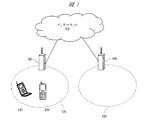
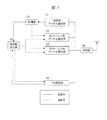
図1は、本発明に関わるマルチモード無線通信方式のシステム構成を表す構成図である。図2はこのマルチモード無線通信方式で用いられるアクセスポイント(基地局)の構成を表す構成図である。また、図3はこのマルチモード無線通信方式で用いられる端末の構成図である。 FIG. 1 is a configuration diagram showing a system configuration of a multimode wireless communication system according to the present invention. FIG. 2 is a block diagram showing the configuration of an access point (base station) used in this multimode wireless communication system. FIG. 3 is a block diagram of a terminal used in this multimode wireless communication system.
このマルチモード無線通信方式ではアクセスポイント300とアクセスポイント400がインターネット500を介して接続される。各アクセスポイントは、該アクセスポイントと通信可能な所定の範囲のアクセスポイントエリアを有する。図1において、アクセスポイント300はアクセスポイントエリア320、アクセスポイント400はアクセスポイントエリア420を各々有する。このアクセスポイントエリアに端末100、200が入ると各アクセスポイントに該当する端末との間で通信が可能となる。
In this multimode wireless communication system, the
本実施の形態における各アクセスポイントは、共用部310、切り替え回路311、WAVE通信部312、WiFi通信部313、DSRC通信部314を含んで構成される。
Each access point in the present embodiment includes a shared
共用部310は通信方式(WAVE通信部312、WiFi通信部313、DSRC通信部314など)によるフィルタやアンプ、給電点の調整に際し、可変機構等を有し共用できる部分をまとめた回路を言う。なお、フィルタやアンプを全てWAVE通信部312等の通信方式に依存した回路に含めても問題は無い。
The shared
切り替え回路311は、WAVE通信部312等の通信方式に依存した回路のうちいずれを用いるかを切り替えるためのスイッチである。
The
WAVE通信部312は、車載用のWAVE(Wireless Access in Vehicle Environment)規格に対応した送受信回路である。WAVE規格は5.9GHzの周波数帯域に対応している。WAVE通信部312は、規格に対応し、制御チャネルと1以上のサービス用チャネルを有している。
The WAVE
WiFi通信部313は、WiFi(Wireless Fidelity)に対応した送受信回路である。WiFiはIEEE802.11の相互接続認証規格であるため、時代によって変化するが、ここでは2.4GHz(IEEE802.11b)、4.9GHz(IEEE802.11j)、5GHz(IEEE802.11j)の各周波数帯域に対応する。WiFi通信部313は1以上のサービス用チャネルを有していることを想定する。
The
DSRC通信部314は料金収受システム(日本国内ではETC)で採用されているIEEE802.11P準拠のDSRC(Dedicated Short Range Communication)に対応した送受信回路である。DSRC通信部314は5.8GHzと700MHzの各周波数帯域に対応することを想定している。上述の通りDSRCもIEEE802.11に対応しているため1以上のサービスチャンネルを有する。
The
これらの通信規格ごとにアクセスポイントのアクセスポイントエリアは広狭する。一部の規格しか使えない範囲も存在するが、ここでは3つ全てが使える範囲をアクセスポイントのアクセスポイントエリアとする。 The access point area of the access point varies depending on these communication standards. There is a range where only some standards can be used, but here, the range where all three can be used is defined as the access point area of the access point.
また、WAVE通信部312、WiFi通信部313、DSRC通信部314はそれぞれ独立に動作している。また、これらはそれぞれインターネットに接続されている。
Also, the
このアクセスポイント300においては、WAVE通信部312が制御用チャネル及び1以上のサービス用チャネルを担当し、DSRC通信部314が優先度の高い1以上のサービス用チャネルを、WiFi通信部313が優先度の低い1以上のサービス用チャネルをそれぞれ担当する。
In this
次に端末100、200について説明する。
Next, the
各端末は制御用チャネル通信部101、第1サービス用チャネル通信部102、第2サービス用チャネル通信部103、干渉検出部105、共用部106、制御部107、周波数設定部108を含んで構成される。
Each terminal includes a control
制御用チャネル通信部101はIEEE802.11p(WAVE)規格の制御チャネルを動作させるための送受信回路である。すなわち、WAVE通信部312と対になる通信モジュールである。制御チャネルは同一のアクセスポイントに接続されている端末全てで用いる共通チャネルである。制御チャネル中に流れるフレームは制御部107での復号を行うこととなる。復号後、制御チャネルの中に自端末を識別するIDが含まれていた場合には自端末向けの呼と認識する。
The control
第1サービス用チャネル通信部102及び第2サービス用チャネル通信部103はサービス用チャネルを動作させるための送受信回路である。本端末では、第1サービス用チャネル通信部102を高優先度の、第2サービス用チャネル通信部103を低優先度のサービス用チャネルを担当することを想定する。
The first service
記述の通りDSRC通信部314を優先度の高いサービス用チャネル、WiFi通信部313が優先度の低いサービス用チャネルを担当するとした場合、第1サービス用チャネル通信部102とDSRC通信部314が、第2サービス用チャネル通信部103とWiFi通信部313がそれぞれ対となって通信を行うこととなる。
As described above, when the
干渉検出部105は使用を想定する周波数帯域がすでに他の端末によって使用されているかを判断する回路である。既に使用されていればその帯域をさらに用いようとすれば干渉が生じることとなる。干渉検出部105は、WiFi通信部313及びDSRC通信部314で用いる周波数帯の干渉の検出が行える必要がある。
The
共用部106は、フィルタやアンプ、給電点の調整に際し、可変機構等を有し各通信方式に対応して共用できる部分をまとめた回路を言う。
The shared
制御部107は第1サービス用チャネル通信部102、第2サービス用チャネル通信部103がいずれの通信方式に対応するか、周波数設定部108の動作を制御するための制御回路である。また、制御用チャネル通信部101から渡される制御チャネル内包のデータの復号も行う。
The
周波数設定部108は、第1サービス用チャネル通信部102、第2サービス用チャネル通信部103および干渉検出部105の用いる周波数を設定するための設定回路である。
The frequency setting unit 108 is a setting circuit for setting the frequencies used by the first service
次に端末の動作について図4を用いて説明する。図4は、本発明に関わる端末の制御チャンネル処理動作を表すフローチャートである。 Next, the operation of the terminal will be described with reference to FIG. FIG. 4 is a flowchart showing the control channel processing operation of the terminal according to the present invention.
端末は待ち受け時に、制御用チャネル通信部101で下り制御チャネルを受信する(S200)。この受信した制御チャネルをまず復号化し、自身への送信か否かを確認する(S201)。以下、このフローチャートでは、このフレームが自身に送られてきているものとして説明する。
When the terminal is on standby, the control
図5は、この受信する制御チャネルのフレーム構成を表す構成図である。 FIG. 5 is a configuration diagram showing the frame configuration of the received control channel.
この下り制御チャネルは、メッセージ種別401、端末ID402、無線通信方式403を含むフレームより構成される。制御チャネル上には上記フレームを連続的または断続的に出力する。図5ではフレーム#0及びフレーム#1が連続して出力されることを想定している。
This downlink control channel is composed of a frame including a
メッセージ種別401は該フレームに含まれる該メッセージの種類を現すデータフィールドである。このメッセージ種別401中に記載されるデータには優先度を含む。緊急呼は優先度を高く設定する。
A
端末ID402は呼び出し対象の端末を特定するための端末IDを記載するデータフィールドである。制御チャネルが復号化した際には、端末はまずこのデータフィールドを確認し、自身へのメッセージか否かを確認する。ステップS201ではこの端末IDを見て自端末向けかを判断している。
The
無線通信方式403は接続時に用いるサービス用チャネルを特定するためのデータフィールドである。「方式名」とはなっているが識別子のような形式であってもよい。
The
図4の説明に戻る。 Returning to the description of FIG.
判定した結果、優先度が高い緊急呼の場合(S202:Yes)、第1サービス用チャネル通信部102を起動する。第1サービス用チャネル通信部102の起動後、制御部107は周波数設定部108に対して干渉検出部105による他の端末の周波数利用状況を確認させる。
As a result of the determination, in the case of an emergency call with a high priority (S202: Yes), the first service
この後、周波数設定部108は、干渉検出部105により検出した空き帯域のうち最も高速に通信が行える周波数を第1サービス用チャネル通信部102の周波数として設定する。あわせて、周波数設定部108は共用部106の設定も行う。
Thereafter, the frequency setting unit 108 sets the frequency at which communication can be performed at the highest speed among the available bands detected by the
これらの設定後、第1サービス用チャネル通信部102、共用部106、及び接続しているアクセスポイントの対応した通信部を経由してインターネット500と接続する(ステップS203)。
After these settings, the first service
制御部107により復号した呼の優先度が低い場合には(S204:Yes)、第2サービス用チャネル通信部103を起動する。第2サービス用チャネル通信部103の起動後、制御部107は周波数設定部108に対して干渉検出部105による他の端末の周波数利用状況を確認させる。
When the priority of the call decoded by the
この後、周波数設定部108は、干渉検出部105により検出した空き帯域のうち最も高速に通信が行える周波数を第2サービス用チャネル通信部103の周波数として設定する。あわせて、周波数設定部108は共用部106の設定も行う。
Thereafter, the frequency setting unit 108 sets the frequency at which communication can be performed at the highest speed among the available bands detected by the
これらの設定後、第2サービス用チャネル通信部103、共用部106、及び接続しているアクセスポイントの対応した通信部を経由してインターネット500と接続する(ステップS205)。
After these settings, the second service
なお、本発明においては、第1サービス用チャネル通信部102ではWAVE規格に、第2サービス用チャネル通信部ではWiFi又はDSRCを想定しているが、必ずしもこれに拘るものではない。
In the present invention, the first service
このようにすることで、大容量のサービス情報を通信するための優先度の低い無線チャネルと、緊急性を要する小容量の情報を通信するための優先度の高い無線チャネルを別チャネルとする。これにより緊急情報を通信する無線チャネルの回線仕様率を下げ、無線LAN規格(IEEE802.11)による送信待ちが生じる確立を下げることができる。結果として、緊急情報の送信に際して、送信待ちに起因する送信の遅延をなくすことが可能となる。 In this way, a low-priority wireless channel for communicating large-capacity service information and a high-priority wireless channel for communicating urgent small-capacity information are set as different channels. As a result, the line specification rate of the radio channel for communicating emergency information can be reduced, and the probability of waiting for transmission according to the wireless LAN standard (IEEE 802.11) can be reduced. As a result, when transmitting emergency information, it is possible to eliminate transmission delays due to transmission waiting.
以上、本発明者によってなされた発明を実施の形態に基づき具体的に説明したが、本発明は前記の実施の形態に限定されるものではなく、その要旨を逸脱しない範囲で種々変更が可能であることは言うまでもない。 As mentioned above, the invention made by the present inventor has been specifically described based on the embodiments. However, the present invention is not limited to the above-described embodiments, and various modifications can be made without departing from the scope of the invention. Needless to say.
本発明は、マルチモード無線通信方式下における緊急呼時における制御チャネルの使用方法に関して説明した。しかし、緊急時通信には限られず、制御チャネルを用いた優先順位の高低を許容した通信方式であれば適用可能である。 The present invention has been described with respect to a method of using a control channel during an emergency call under a multi-mode wireless communication system. However, the communication method is not limited to emergency communication, and any communication method that allows high and low priority using a control channel is applicable.
101…制御用チャネル通信部、102…第1サービス用チャネル通信部、
103…第2サービス用チャネル通信部、105…干渉検出部、
106…共用部、107…制御部、108…周波数設定部、
310…共用部、311…切り替え回路、312…WAVE通信部、
313…WiFi通信部、314…DSRC通信部。
101 ... Control channel communication unit, 102 ... First service channel communication unit,
103 ... second communication channel communication unit, 105 ... interference detection unit,
106 ... shared unit, 107 ... control unit, 108 ... frequency setting unit,
310 ... shared unit, 311 ... switching circuit, 312 ... WAVE communication unit,
313: WiFi communication unit, 314: DSRC communication unit.
Claims (3)
該無線通信装置は、前記制御チャネルで通信を行う制御チャネル通信部と、前記第1のサービス用チャネルで通信を行う第1サービス用チャネル送受信部と、前記第2のサービス用チャネルで通信を行う第2サービス用チャネル送受信部と、制御部と、周波数設定部と、干渉検出部と、を有し、
前記制御部は前記制御チャネル通信部で受信した制御チャネルのフレームを復号し、
該復号後のフレームが自身への通信要求である場合前記フレームの通信優先度を検出し、
前記通信優先度で使用する周波数の使用状況を前記干渉検出部で検出し、
高い優先度を持つ前記フレームの接続が可能なときに前記制御部は前記第1サービス用チャネル送受信部の動作周波数を前記周波数設定部に設定させ、かつ前記干渉検出部に使用するチャネルの空き状況を確認させ、
低い優先度を持つ前記フレームの接続が可能なときに前記制御部は前記第2サービス用チャネル送受信部の動作周波数を前記周波数設定部に設定させかつ前記干渉検出部に使用するチャネルの空き状況を確認させることを特徴とする無線通信装置。 Wireless communication system having a control channel shared by a plurality of wireless communication devices having a link with a base station, a first service channel having a high priority, and a second service channel having a low priority A wireless communication device corresponding to
The wireless communication apparatus performs communication using the control channel communication unit that performs communication using the control channel, the first service channel transmission / reception unit that performs communication using the first service channel, and the second service channel. A second service channel transmission / reception unit, a control unit, a frequency setting unit, and an interference detection unit;
The control unit decodes a frame of the control channel received by the control channel communication unit,
If the decoded frame is a communication request to itself, the communication priority of the frame is detected,
The use state of the frequency used in the communication priority is detected by the interference detection unit,
When the frame having a high priority is connectable, the control unit causes the frequency setting unit to set the operating frequency of the first service channel transmission / reception unit, and the availability of the channel used for the interference detection unit Check
When the connection of the frame having a low priority is possible, the control unit causes the frequency setting unit to set the operating frequency of the second service channel transmission / reception unit and determines the availability of a channel used for the interference detection unit. A wireless communication device characterized by being confirmed.
該無線通信装置は、前記制御チャネルで通信を行う制御チャネル通信部と、前記第1のサービス用チャネルで通信を行う第1サービス用チャネル送受信部と、前記第2のサービス用チャネルで通信を行う第2サービス用チャネル送受信部と、制御部と、周波数設定部と、干渉検出部と、を有し、
前記制御部が、前記制御チャネル通信部で受信した制御チャネルのフレームを復号するフレーム復号ステップと、
前記フレーム復号ステップで復号したフレームから、前記制御部がメッセージ種別データフィールドを抽出するメッセージ種別データフィールド抽出ステップと、
前記メッセージ種別データフィールド抽出ステップで抽出したメッセージ種別データフィールドから、前記制御部が接続するサービス用チャネルの優先度を求め、前記第1サービス用チャネル送受信部あるいは前記第2サービス用チャネル送受信部のいずれを用いるか決定するサービス用チャネル送受信部選択ステップと、
前記サービス用チャネル送受信部選択ステップで決定したサービス用チャネル送受信部で使用する周波数の使用状況を前記干渉検出部に検出させる想定周波数空き状況検出ステップと、
前記制御部が前記周波数設定部に対して、前記想定周波数空き状況検出ステップで前記干渉検出部が検出した空き周波数にサービス用チャネル送受信部選択ステップで決定した前記サービス用チャネル送受信部を設定させるサービス用チャネル送受信部周波数設定ステップと、を含むことを特徴とする無線通信装置の通信方法。 Wireless communication system having a control channel shared by a plurality of wireless communication devices having a link with a base station, a first service channel having a high priority, and a second service channel having a low priority A communication method of a wireless communication device corresponding to
The wireless communication apparatus performs communication using the control channel communication unit that performs communication using the control channel, the first service channel transmission / reception unit that performs communication using the first service channel, and the second service channel. A second service channel transmission / reception unit, a control unit, a frequency setting unit, and an interference detection unit;
A frame decoding step in which the control unit decodes a frame of the control channel received by the control channel communication unit;
A message type data field extraction step in which the control unit extracts a message type data field from the frame decoded in the frame decoding step;
From the message type data field extracted in the message type data field extracting step, the priority of the service channel to which the control unit is connected is obtained, and either the first service channel transmitting / receiving unit or the second service channel transmitting / receiving unit is determined. A service channel transmitter / receiver selection step for determining whether to use
An assumed frequency vacancy state detecting step for causing the interference detecting unit to detect the usage state of the frequency used in the service channel transmitting / receiving unit determined in the service channel transmitting / receiving unit selecting step;
Service in which the control unit causes the frequency setting unit to set the service channel transmission / reception unit determined in the service channel transmission / reception unit selection step to the free frequency detected by the interference detection unit in the assumed frequency free state detection step A communication method for a wireless communication device, comprising: a channel transmission / reception unit frequency setting step.
Priority Applications (3)
| Application Number | Priority Date | Filing Date | Title |
|---|---|---|---|
| JP2009173877A JP2011029952A (en) | 2009-07-27 | 2009-07-27 | Wireless communication apparatus, and communication method of the same |
| US12/838,415 US8249637B2 (en) | 2009-07-27 | 2010-07-16 | Wireless communication device and communication method of wireless communication device |
| CN2010102397972A CN101969630A (en) | 2009-07-27 | 2010-07-26 | Wireless communication device and communication method of wireless communication device |
Applications Claiming Priority (1)
| Application Number | Priority Date | Filing Date | Title |
|---|---|---|---|
| JP2009173877A JP2011029952A (en) | 2009-07-27 | 2009-07-27 | Wireless communication apparatus, and communication method of the same |
Publications (1)
| Publication Number | Publication Date |
|---|---|
| JP2011029952A true JP2011029952A (en) | 2011-02-10 |
Family
ID=43497792
Family Applications (1)
| Application Number | Title | Priority Date | Filing Date |
|---|---|---|---|
| JP2009173877A Pending JP2011029952A (en) | 2009-07-27 | 2009-07-27 | Wireless communication apparatus, and communication method of the same |
Country Status (3)
| Country | Link |
|---|---|
| US (1) | US8249637B2 (en) |
| JP (1) | JP2011029952A (en) |
| CN (1) | CN101969630A (en) |
Cited By (2)
| Publication number | Priority date | Publication date | Assignee | Title |
|---|---|---|---|---|
| JP2012205110A (en) * | 2011-03-25 | 2012-10-22 | Fujitsu Ltd | Communication device, communication method and communication program |
| JP2016523461A (en) * | 2013-05-31 | 2016-08-08 | クゥアルコム・インコーポレイテッドQualcomm Incorporated | DSRC listening mode for WI-FI to use DSRC spectrum |
Families Citing this family (7)
| Publication number | Priority date | Publication date | Assignee | Title |
|---|---|---|---|---|
| TWI451780B (en) * | 2010-10-08 | 2014-09-01 | Inst Information Industry | Service providing apparatus, service consuming apparatus, and service transmitting method thereof |
| US20130039237A1 (en) * | 2011-08-12 | 2013-02-14 | Keiichi Kubota | Method and Apparatus for Transmission Protocol Uplink Channel Selection |
| US8437302B2 (en) | 2011-08-12 | 2013-05-07 | Renesas Mobile Corporation | Method and apparatus for transmission protocol uplink channel selection |
| CA2917301C (en) * | 2013-07-02 | 2021-12-14 | Hoang T. Pham | Heat activated shrink films |
| WO2015004316A1 (en) * | 2013-07-12 | 2015-01-15 | Upm Raflatac Oy | Multilayer film for label and a method for providing such |
| JP6358204B2 (en) * | 2015-09-04 | 2018-07-18 | 株式会社デンソー | Wireless communication device |
| JP6406194B2 (en) * | 2015-09-17 | 2018-10-17 | 株式会社デンソー | Communication device |
Citations (14)
| Publication number | Priority date | Publication date | Assignee | Title |
|---|---|---|---|---|
| JPH10501669A (en) * | 1995-03-31 | 1998-02-10 | モトローラ・インコーポレイテッド | Method and apparatus for allocating communication resources to support priority communication in a communication system |
| JPH11136732A (en) * | 1997-11-04 | 1999-05-21 | Omron Corp | Radio data communication equipment |
| JP2000092203A (en) * | 1998-09-07 | 2000-03-31 | Matsushita Electric Ind Co Ltd | Voice message notification system |
| JP2001053745A (en) * | 1999-08-11 | 2001-02-23 | Nippon Telegr & Teleph Corp <Ntt> | Radio packet communication system |
| JP2003008531A (en) * | 2001-06-19 | 2003-01-10 | Mitsubishi Electric Corp | Tdma communication system and tdma communication method |
| JP2003244753A (en) * | 2002-02-20 | 2003-08-29 | Ntt Docomo Inc | Channel assignment method and channel assignment apparatus |
| JP2003319448A (en) * | 2002-04-23 | 2003-11-07 | Sony Corp | Method and apparatus for radio communicating |
| JP2004356888A (en) * | 2003-05-28 | 2004-12-16 | Ntt Docomo Inc | Radio control station, radio terminal, base station, communication system, and communicvation method |
| JP2008117038A (en) * | 2006-11-01 | 2008-05-22 | Hitachi Kokusai Electric Inc | Disaster information transmission system |
| JP2008187555A (en) * | 2007-01-31 | 2008-08-14 | Hitachi Ltd | Radio communication system and terminal |
| WO2008156064A1 (en) * | 2007-06-19 | 2008-12-24 | Ntt Docomo, Inc. | Base station device and communication control method |
| WO2009025241A1 (en) * | 2007-08-17 | 2009-02-26 | Ntt Docomo, Inc. | User equipment and wireless communication system |
| JP2009100434A (en) * | 2007-10-17 | 2009-05-07 | Korea Electronics Telecommun | Method for transmitting signal and method for receiving signal |
| JP2009165060A (en) * | 2008-01-10 | 2009-07-23 | Toshiba Corp | Radio communication device, radio communication method and communication program |
Family Cites Families (18)
| Publication number | Priority date | Publication date | Assignee | Title |
|---|---|---|---|---|
| US4594591A (en) * | 1982-07-28 | 1986-06-10 | Motorola, Inc. | General purpose data control terminal |
| DE3889221T2 (en) * | 1988-10-20 | 1994-11-17 | Ibm | Communication network. |
| JPH10229420A (en) * | 1997-02-17 | 1998-08-25 | Matsushita Electric Ind Co Ltd | Communication system |
| GB9718743D0 (en) * | 1997-09-05 | 1997-11-12 | Philips Electronics Nv | Transmission method and communication system employing the method |
| JP4056018B2 (en) * | 1998-01-23 | 2008-03-05 | 株式会社東芝 | Point / multipoint communication system |
| US6611519B1 (en) * | 1998-08-19 | 2003-08-26 | Swxtch The Rules, Llc | Layer one switching in a packet, cell, or frame-based network |
| JP3183343B2 (en) * | 1999-02-26 | 2001-07-09 | 日本電気株式会社 | Data communication method, terminal device, relay device, data communication system and recording medium thereof |
| JP4007196B2 (en) * | 2003-01-15 | 2007-11-14 | 株式会社日立製作所 | Digital data transmission device |
| JP4211529B2 (en) * | 2003-08-06 | 2009-01-21 | 日本電気株式会社 | Channel selection method and radio station and program used therefor |
| CN100399849C (en) * | 2005-03-31 | 2008-07-02 | 联想(北京)有限公司 | Multi-mode coexistence method for multi mode communication equipment |
| JP4671777B2 (en) * | 2005-06-17 | 2011-04-20 | 株式会社エヌ・ティ・ティ・ドコモ | Shared data channel allocation apparatus and shared data channel allocation method |
| KR100717962B1 (en) * | 2005-07-15 | 2007-05-14 | 전자부품연구원 | Method of controlling data transmission in a wireless network having many nodes and sensor network system using the same and computer readable media using the same |
| JP4628331B2 (en) | 2005-09-26 | 2011-02-09 | パナソニック株式会社 | Multi-mode wireless communication apparatus and wireless communication method |
| JP4812479B2 (en) * | 2006-03-20 | 2011-11-09 | 株式会社エヌ・ティ・ティ・ドコモ | Mobile station and peripheral cell measurement method |
| JP4754463B2 (en) | 2006-11-24 | 2011-08-24 | 株式会社Kddi研究所 | Communication route selection control device, wireless device, and communication route selection method |
| CN101350134A (en) * | 2008-08-29 | 2009-01-21 | 同济大学 | Mechanism and system for transmitting vehicle emergency message based on DSRC |
| KR101151199B1 (en) * | 2008-12-16 | 2012-06-08 | 한국전자통신연구원 | Wireless communication system of smart type and method for the same |
| US8144732B2 (en) * | 2008-12-31 | 2012-03-27 | Mediatek Inc. | Method for boosting downlink transmission to mobile station and system utilizing the same |
-
2009
- 2009-07-27 JP JP2009173877A patent/JP2011029952A/en active Pending
-
2010
- 2010-07-16 US US12/838,415 patent/US8249637B2/en not_active Expired - Fee Related
- 2010-07-26 CN CN2010102397972A patent/CN101969630A/en active Pending
Patent Citations (14)
| Publication number | Priority date | Publication date | Assignee | Title |
|---|---|---|---|---|
| JPH10501669A (en) * | 1995-03-31 | 1998-02-10 | モトローラ・インコーポレイテッド | Method and apparatus for allocating communication resources to support priority communication in a communication system |
| JPH11136732A (en) * | 1997-11-04 | 1999-05-21 | Omron Corp | Radio data communication equipment |
| JP2000092203A (en) * | 1998-09-07 | 2000-03-31 | Matsushita Electric Ind Co Ltd | Voice message notification system |
| JP2001053745A (en) * | 1999-08-11 | 2001-02-23 | Nippon Telegr & Teleph Corp <Ntt> | Radio packet communication system |
| JP2003008531A (en) * | 2001-06-19 | 2003-01-10 | Mitsubishi Electric Corp | Tdma communication system and tdma communication method |
| JP2003244753A (en) * | 2002-02-20 | 2003-08-29 | Ntt Docomo Inc | Channel assignment method and channel assignment apparatus |
| JP2003319448A (en) * | 2002-04-23 | 2003-11-07 | Sony Corp | Method and apparatus for radio communicating |
| JP2004356888A (en) * | 2003-05-28 | 2004-12-16 | Ntt Docomo Inc | Radio control station, radio terminal, base station, communication system, and communicvation method |
| JP2008117038A (en) * | 2006-11-01 | 2008-05-22 | Hitachi Kokusai Electric Inc | Disaster information transmission system |
| JP2008187555A (en) * | 2007-01-31 | 2008-08-14 | Hitachi Ltd | Radio communication system and terminal |
| WO2008156064A1 (en) * | 2007-06-19 | 2008-12-24 | Ntt Docomo, Inc. | Base station device and communication control method |
| WO2009025241A1 (en) * | 2007-08-17 | 2009-02-26 | Ntt Docomo, Inc. | User equipment and wireless communication system |
| JP2009100434A (en) * | 2007-10-17 | 2009-05-07 | Korea Electronics Telecommun | Method for transmitting signal and method for receiving signal |
| JP2009165060A (en) * | 2008-01-10 | 2009-07-23 | Toshiba Corp | Radio communication device, radio communication method and communication program |
Cited By (2)
| Publication number | Priority date | Publication date | Assignee | Title |
|---|---|---|---|---|
| JP2012205110A (en) * | 2011-03-25 | 2012-10-22 | Fujitsu Ltd | Communication device, communication method and communication program |
| JP2016523461A (en) * | 2013-05-31 | 2016-08-08 | クゥアルコム・インコーポレイテッドQualcomm Incorporated | DSRC listening mode for WI-FI to use DSRC spectrum |
Also Published As
| Publication number | Publication date |
|---|---|
| CN101969630A (en) | 2011-02-09 |
| US8249637B2 (en) | 2012-08-21 |
| US20110021233A1 (en) | 2011-01-27 |
Similar Documents
| Publication | Publication Date | Title |
|---|---|---|
| JP2011029952A (en) | Wireless communication apparatus, and communication method of the same | |
| CN111213424B (en) | Method for transmitting side link message by terminal in wireless communication system and terminal using the same | |
| US10856335B2 (en) | Base station, terminal device, and communication method | |
| US10637620B2 (en) | Communication device, base station and communication method | |
| CN110268767B (en) | Terminal device, base station, method, and recording medium | |
| US10798738B2 (en) | Device and method | |
| KR102480438B1 (en) | Electronic device and radio communication method | |
| JP2005277964A (en) | Mobile terminal communication restriction apparatus, and method and control program for communication restriction therefor | |
| CA3023184A1 (en) | Electronic apparatus, information processing device and information processing method | |
| CN112398626A (en) | Information transmission method, communication device and system | |
| WO2012087926A1 (en) | Method and device for detecting a channel | |
| KR101780889B1 (en) | Dsrc listen mode for wi-fi using dsrc spectrum | |
| CN109328478B (en) | Resource processing method and device and terminal | |
| JP2009164863A (en) | Mobile station | |
| CN113853016A (en) | Cross-system interference avoidance method, device and system | |
| JP5355236B2 (en) | Communication device | |
| WO2023202473A1 (en) | User equipment, wireless communication method, and computer-readable storage medium | |
| KR100922721B1 (en) | OBE possible DSRC and vehicles communication and method. | |
| WO2019214493A1 (en) | User equipment, electronic device, wireless communication method, and storage medium | |
| CN115918122A (en) | Electronic device, wireless communication method, and non-transitory computer-readable storage medium | |
| CN115707112A (en) | Electronic device, wireless communication method, and computer-readable storage medium | |
| CN114747247A (en) | Electronic device, wireless communication method, and computer-readable storage medium | |
| CN109699201A (en) | The method and apparatus for transmitting data | |
| JP2008118459A (en) | Radio communication system, radio base station and incoming signal receiving method therefor |
Legal Events
| Date | Code | Title | Description |
|---|---|---|---|
| A621 | Written request for application examination |
Free format text: JAPANESE INTERMEDIATE CODE: A621 Effective date: 20120607 |
|
| A977 | Report on retrieval |
Free format text: JAPANESE INTERMEDIATE CODE: A971007 Effective date: 20130117 |
|
| A131 | Notification of reasons for refusal |
Free format text: JAPANESE INTERMEDIATE CODE: A131 Effective date: 20130122 |
|
| A02 | Decision of refusal |
Free format text: JAPANESE INTERMEDIATE CODE: A02 Effective date: 20130528 |