JP5355236B2 - Communication device - Google Patents
Communication device Download PDFInfo
- Publication number
- JP5355236B2 JP5355236B2 JP2009139500A JP2009139500A JP5355236B2 JP 5355236 B2 JP5355236 B2 JP 5355236B2 JP 2009139500 A JP2009139500 A JP 2009139500A JP 2009139500 A JP2009139500 A JP 2009139500A JP 5355236 B2 JP5355236 B2 JP 5355236B2
- Authority
- JP
- Japan
- Prior art keywords
- frame
- communication
- emergency
- emergency communication
- vehicle
- Prior art date
- Legal status (The legal status is an assumption and is not a legal conclusion. Google has not performed a legal analysis and makes no representation as to the accuracy of the status listed.)
- Expired - Fee Related
Links
Images


Landscapes
- Mobile Radio Communication Systems (AREA)
Description
本発明は、アドホックネットワークで緊急無線通信を行う通信装置に関する。 The present invention relates to a communication apparatus that performs emergency wireless communication in an ad hoc network.
従来、無線基地局を必要とせず、各無線端末が対等に接続してネットワークを構成するアドホックネットワークがある。アドホックネットワークは、災害などで既存のセルラネットワークが使用できない場合やトラフィックが輻輳している場合において、携帯電話機と救助側との通信を可能にする技術として応用されている。例えば、中継センサを災害地域に散布し、中継センサが、携帯電話機の位置情報を含む災害情報を周囲にブロードキャストすることで、救助隊員が被災者の位置情報を取得することができる。このような技術が、下記特許文献1において開示されている。
2. Description of the Related Art Conventionally, there is an ad hoc network in which a wireless base station is not required and each wireless terminal is connected equally to form a network. The ad hoc network is applied as a technology that enables communication between the mobile phone and the rescue side when an existing cellular network cannot be used due to a disaster or when traffic is congested. For example, the relay sensor is dispersed in the disaster area, and the relay sensor broadcasts disaster information including the location information of the mobile phone to the surroundings, so that the rescue team member can acquire the location information of the victim. Such a technique is disclosed in
また、アドホックネットワークは、車車間通信にも利用されている。通信を行う車両は、CSMA/CA(Carrier Sense Multiple Access/Collision Avoidance)により、輻輳を発生させることなく、パケットの衝突を回避している。また、QoS(Quality of Service)の優先順位の高い緊急通信については、一般の通信よりも送出タイミングを早くすることで、優先的に行うことができる。一方で、直接通信できない複数の車両が同じ車両に対してパケットを送信する場合には、CSMA/CAが機能せずパケット衝突が発生する。いわゆる、隠れ端末の問題である。しかしながら、この場合でも、緊急通信を行う車両が、事前に周辺の車両に対して送信を停止させる信号を発信し、周辺の車両が当該信号をブロードキャストすることで、隠れ端末の車両の送信も停止させることができ、パケット衝突を回避した緊急通信を行うことができる。 Ad hoc networks are also used for inter-vehicle communication. A vehicle that performs communication avoids packet collision without causing congestion by CSMA / CA (Carrier Sense Multiple Access / Collision Avoidance). In addition, emergency communication with a high priority of QoS (Quality of Service) can be preferentially performed by setting the transmission timing earlier than general communication. On the other hand, when a plurality of vehicles that cannot communicate directly transmit packets to the same vehicle, CSMA / CA does not function and packet collision occurs. This is a so-called hidden terminal problem. However, even in this case, the vehicle that performs emergency communication sends a signal to stop transmission to surrounding vehicles in advance, and the surrounding vehicle broadcasts the signal, thereby stopping transmission of the hidden terminal vehicle. Emergency communication that avoids packet collision can be performed.
しかしながら、上記従来の技術によれば、隠れ端末の問題を解消するためにブロードキャストされた信号が繰り返し転送されると、アドホックネットワーク内で輻輳が発生し、緊急通信を行う端末に干渉しない端末の通信まで停止させてしまう。そのため、ネットワーク内のスループットが低下する、という問題があった。 However, according to the above-described conventional technique, when a broadcast signal is repeatedly transferred to solve the problem of the hidden terminal, congestion occurs in the ad hoc network, and the terminal communication that does not interfere with the terminal that performs emergency communication. Will stop until. Therefore, there is a problem that the throughput in the network is lowered.
本発明は、上記に鑑みてなされたものであって、アドホックネットワークにおいて、ネットワーク内のスループットを低下させることなく緊急無線通信を行うことが可能な通信装置を得ることを目的とする。 The present invention has been made in view of the above, and an object of the present invention is to obtain a communication device capable of performing emergency wireless communication in an ad hoc network without reducing the throughput in the network.
上述した課題を解決し、目的を達成するために、本発明は、アドホックネットワークで緊急無線通信を行う通信装置であって、通常通信フレームと異なるフレーム構成の緊急通信フレームを生成して送信する送信手段と、緊急通信フレームを検出可能な受信手段と、を備えることを特徴とする。 In order to solve the above-described problems and achieve the object, the present invention is a communication device that performs emergency wireless communication in an ad hoc network, and generates and transmits an emergency communication frame having a frame configuration different from that of a normal communication frame. Means and receiving means capable of detecting an emergency communication frame.
本発明によれば、スループットを低下させることなく緊急無線通信を行うことができる、という効果を奏する。 According to the present invention, it is possible to perform emergency wireless communication without reducing the throughput.
以下に、本発明にかかる通信装置の実施の形態を図面に基づいて詳細に説明する。なお、この実施の形態によりこの発明が限定されるものではない。 Embodiments of a communication apparatus according to the present invention will be described below in detail with reference to the drawings. Note that the present invention is not limited to the embodiments.
実施の形態.
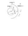
図1は、本実施の形態にかかるアドホックネットワーク無線システムの構成例を示す図である。アドホックネットワーク無線システムは、車両1〜10で構成される。各車両は、周辺の車両とアドホックネットワークを構成して無線通信を行うことができる通信装置を搭載している。ここでは、車両1が緊急通信を開始する場合を想定する。
Embodiment.
FIG. 1 is a diagram illustrating a configuration example of an ad hoc network radio system according to the present embodiment. The ad hoc network wireless system includes
図1のアドホックネットワーク無線システムにおいて、緊急通信エリアE1は、車両1が直接緊急通信を行うことができるエリアを示す。ここでは、車両1以外に車両2〜5が緊急通信エリアE1に在圏している。隠れ端末エリアE2は、車両1が直接緊急通信を行うことはできないが、緊急通信エリアE1に存在する車両2〜5のいずれかが直接通信を行うことができるエリアを示す。ここでは、車両6〜8が隠れ端末エリアE2に在圏している。車両6〜8が、車両1における隠れ端末である。非輻輳端末エリアE3は、緊急通信エリアE1内の車両1〜5とは直接通信を行うことができないエリアを示す。ここでは、車両9〜10が非輻輳端末エリアE3に在圏している。
In the ad hoc network wireless system of FIG. 1, the emergency communication area E <b> 1 indicates an area where the
従来では、緊急通信を開始する車両1が、CSMA/CA(Carrier Sense Multiple Access/Collision Avoidance)などにより、緊急通信エリアE1内の車両と送信タイミングを調整することでパケット衝突を回避しようとしても、例えば、車両1と車両8との間ではCSMA/CAが機能しないため、車両1と車両8が同時にパケットを送信した場合に車両5においてパケット衝突が発生する。パケット衝突を回避する方法として、車両1が送信を停止させる(待機状態にする)ための制御フレームを周辺の車両2〜5に送信し、車両2〜5が制御フレームを転送することで、車両6〜8が制御フレームを受信して待機状態に入ることができる。しかし、制御フレームが繰り返し転送されると、緊急通信エリアE1内の車両と干渉しない非輻輳端末エリアE3内の車両9、10に対しても送信を停止させてしまい、ネットワーク内でのスループットが低下する。
Conventionally, even if the
本実施の形態では、緊急通信に使用するフレームとして、通常の通信に使用するフレームとは異なる系列を採用する。図2は、通常通信フレームと緊急通信フレームの構成例を示す図である。通常通信フレームは、プリアンブルを除いた領域は、64ポイントで構成されている。一方、緊急通信フレームは、全体として16384ポイントのフレームとして構成されている。緊急通信フレームは、通常通信フレームと比較すると16384/64=256倍(=24dB)となるので、利得を24dB上げることができる。すなわち、緊急通信を開始する車両1から、非常に相関特性の良い系列のフレームを送信し、受信側の車両で当該フレームを検出できれば、通常の通信として成り立つ信号レベルよりも24dB低いレベルの信号を検出可能となる。これにより、車両1は、緊急通信エリアE1よりも広いエリアに在圏する車両に対して、直接緊急通信の開始を通知することができる。なお、緊急通信フレームのポイント数を変えることで、通常通信フレームとの利得を調整することができる。
In this embodiment, a frame different from a frame used for normal communication is adopted as a frame used for emergency communication. FIG. 2 is a diagram illustrating a configuration example of a normal communication frame and an emergency communication frame. In the normal communication frame, the area excluding the preamble is composed of 64 points. On the other hand, the emergency communication frame is configured as a frame of 16384 points as a whole. Since the emergency communication frame is 16384/64 = 256 times (= 24 dB) compared to the normal communication frame, the gain can be increased by 24 dB. That is, if a frame of a sequence having a very good correlation characteristic is transmitted from the
各車両が搭載する通信装置は、通常通信フレームとポイントが異なる緊急通信フレームを送信できる送信部、および、受信した際に緊急通信フレームを検出可能な受信部を備える。緊急通信フレームを送信する送信部は、大きなポイントのフレームを生成することができればよく、フレームを生成する構成以外は従来同等である。一方、緊急通信フレームを検出する受信部は、緊急通信フレームを検出可能な構成を備える。 The communication device mounted on each vehicle includes a transmission unit capable of transmitting an emergency communication frame having a point different from that of the normal communication frame, and a reception unit capable of detecting the emergency communication frame when received. The transmission unit that transmits the emergency communication frame only needs to be able to generate a large point frame, and is the same as the conventional one except for the configuration for generating the frame. On the other hand, the receiving unit for detecting the emergency communication frame has a configuration capable of detecting the emergency communication frame.
図3は、通信装置における受信部の構成例を示す図である。受信部は、信号処理部11と、復号部12と、制御部13と、緊急信号検出部14と、復号部15と、を備える。信号処理部11は、受信した信号フレームに対してフィルタ処理やD/A(Digital/Analogue)変換などの信号処理を行う。復号部12は、信号処理後の通常通信フレームの信号を復号する。制御部13は、車両間で送受信するフレームの制御を行う。緊急通信フレームを受信した場合は、通常通信フレームの送受信を停止して待機状態に入る。緊急信号検出部14は、信号処理されたフレームから緊急通信フレームを検出する。緊急通信フレームは、通常通信フレームよりも相関特性の良い系列を採用しているため、通常の通信として成り立たない(検出できない)受信レベルの低いフレームを検出できる。復号部15は、緊急信号検出後の緊急通信フレームの信号を復号する。 FIG. 3 is a diagram illustrating a configuration example of a receiving unit in the communication apparatus. The receiving unit includes a signal processing unit 11, a decoding unit 12, a control unit 13, an emergency signal detection unit 14, and a decoding unit 15. The signal processing unit 11 performs signal processing such as filter processing and D / A (Digital / Analogue) conversion on the received signal frame. The decoding unit 12 decodes the signal of the normal communication frame after the signal processing. The control part 13 controls the frame transmitted / received between vehicles. When an emergency communication frame is received, transmission / reception of a normal communication frame is stopped and a standby state is entered. The emergency signal detection unit 14 detects an emergency communication frame from the signal-processed frame. Since the emergency communication frame employs a sequence having a better correlation characteristic than the normal communication frame, it is possible to detect a frame with a low reception level that is not established (cannot be detected) as normal communication. The decoding unit 15 decodes the signal of the emergency communication frame after the emergency signal is detected.
例えば、車両1が緊急通信フレームを送信した場合、周辺の車両は、通常通信フレームよりも低い受信レベルでも検出できる。そのため、隠れ端末エリアE2内の車両6〜8では、緊急信号検出部14で緊急通信フレームを検出できた場合、制御部13の制御により待機状態に入ることができる。これにより、車両1は、隠れ端末エリアE2に在圏する車両についても、直接待機状態にさせてから緊急通信を開始できる。すなわち、隠れ端末問題を発生させることなく緊急通信を開始できる。緊急通信フレームが非輻輳端末エリアE3まで届いた場合でも、車両1からは距離があり十分に減衰していると考えられるので、車両9、10では、緊急信号検出部14でも緊急通信フレームを検出できず、制御部13において待機状態に入らないので非輻輳端末エリアE3内の通信に干渉を与えない。緊急通信フレームのポイントによって通常通信フレームとの利得を調整可能なため、隠れ端末エリアE2の範囲内で緊急通信フレームとして検出できるようにすることも可能である。
For example, when the
このように、緊急通信フレームを送受信することは、通常通信とは時間的に無相関でできるので、TDMA(Time Division Multiple Access)、CDMA(Code Division Multiple Access)、いずれの方式についても適用可能である。 As described above, the transmission / reception of the emergency communication frame can be uncorrelated with the normal communication in terms of time, and therefore can be applied to any of TDMA (Time Division Multiple Access) and CDMA (Code Division Multiple Access). is there.
なお、緊急性が高く確実に緊急通信メッセージを行き渡らせたい場合には、図1において、車両2〜8が、受信した緊急通信フレームをコピーして転送してもよい。これにより、送信を行っていた端末や偶然受信できなかった車両に対しても緊急通信を通知することが可能になる。ただし、単純にコピーして転送されると、無制限に繰り返される可能性がある。そのため、緊急通信フレームをコピーして転送する車両は、コピーされた緊急通信フレームであることを示すため、車両1が送信したフレームとは異なる相関系列にしてから転送する。これにより、車両1から緊急通信フレームを受信できなかったが、車両2〜8から受信した場合には、コピーされたものと判定可能なため、繰り返し転送される事態を回避できる。
In addition, in the case of high urgency and reliable delivery of emergency communication messages, the
図4は、アドホックネットワーク無線システムの構成例を示す図である。例えば、車両7では、緊急信号検出部14が、何らかの要因で車両1からの緊急通信フレームを受信できなかった場合、車両3から転送された緊急通信フレームを受信することで、制御部13の制御により待機状態に入ることができる。また、車両3から受信した緊急通信フレームがコピーであることがわかるので、制御部13は、転送する制御を行わない。一方、車両7が、車両1から直接緊急フレームを受信できた場合には、制御部13では転送する制御を行い、図示しない送信部において異なる相関系列にした緊急通信フレームを生成して送信をすることで、非輻輳端末エリアE3の車両10まで通知される。車両10は、緊急信号検出部14が転送された緊急通信フレームを受信することで、制御部13の制御により待機状態に入る。このように、非輻輳端末エリアE3の車両にも干渉することになるが、車両1周辺の車両に対しては、確実に緊急通信を通知することができる。
FIG. 4 is a diagram illustrating a configuration example of an ad hoc network wireless system. For example, in the vehicle 7, when the emergency signal detection unit 14 cannot receive the emergency communication frame from the
また、緊急通信を開始する車両では、緊急通信フレームを送信して周辺の車両を待機状態にしてから引き続き緊急通信に関する情報フレームを送信する場合に限らず、緊急性の高い信号が複数ある場合には、配列を変えた相関系列を複数使うことにより、緊急通信フレームに情報を含ませることができる。例えば、図示しない送信部において、緊急通信フレームに、急ブレーキや、右折、左折などの情報を含ませることができる。受信した車両では、緊急信号検出部14で緊急通信フレームを検出し、制御部13で情報の内容を読み取ることができる。緊急通信の内容が分かれば、受信した車両側では、継続して送信される情報フレームの前に、事前の対応を準備することができる。なお、より遠くのエリアまで通知したいのであれば、緊急通信フレームには情報を含ませない。周辺の車両を待機状態にさせるだけのフレームであれば、あらかじめ設定されたポイントのフレームを受信できればよく、解読の必要がないからである。 In addition, in the case of a vehicle that starts emergency communication, not only when an emergency communication frame is transmitted and surrounding vehicles are set in a standby state and then an information frame related to emergency communication is continuously transmitted, but there are a plurality of highly urgent signals. The information can be included in the emergency communication frame by using a plurality of correlation sequences with different arrangements. For example, information such as sudden braking, right turn, left turn, etc. can be included in the emergency communication frame in a transmission unit (not shown). In the received vehicle, the emergency signal detection unit 14 can detect the emergency communication frame, and the control unit 13 can read the content of the information. If the contents of the emergency communication are known, the receiving vehicle can prepare a prior response before the information frame that is continuously transmitted. If it is desired to notify a farther area, information is not included in the emergency communication frame. This is because it is only necessary to receive a frame at a preset point as long as it is a frame that only causes surrounding vehicles to be in a standby state, and there is no need for decoding.
以上説明したように、本実施の形態では、緊急通信を開始する車両は、緊急通信フレームを通常通信フレームよりも大きいポイントで構成し、通常通信として成り立たないエリアまで緊急通信を通知できることとした。これにより、緊急通信フレームを受信した車両は転送を行わず、また、隠れ端末の問題も発生しないことから、ネットワーク内のスループットの低下を回避することができる。 As described above, in the present embodiment, a vehicle that starts emergency communication is configured with an emergency communication frame having points larger than the normal communication frame, and can notify the emergency communication to an area that does not hold as normal communication. As a result, the vehicle that has received the emergency communication frame does not transfer, and the problem of the hidden terminal does not occur, so that a decrease in throughput in the network can be avoided.
以上のように、本発明にかかる通信装置は、アドホックネットワークの通信に有用であり、特に、緊急通信を行う通信装置として適している。 As described above, the communication device according to the present invention is useful for communication in an ad hoc network, and is particularly suitable as a communication device that performs emergency communication.
1、2、3、4、5、6、7、8、9、10 車両
11 信号処理部
12 復号部
13 制御部
14 緊急信号検出部
15 復号部
1, 2, 3, 4, 5, 6, 7, 8, 9, 10 Vehicle 11 Signal processing unit 12 Decoding unit 13 Control unit 14 Emergency signal detection unit 15 Decoding unit
Claims (4)
通常通信フレームと異なるフレーム構成の緊急通信フレームを生成して送信する送信手段と、
緊急通信フレームを検出可能な受信手段と、
を備え、
前記受信手段は、
緊急通信を開始する通信装置からの緊急通信フレームを受信した場合は、フレームの相関系列を変更して緊急通信フレームを転送し、フレームの相関系列が変更された緊急通信フレームを受信した場合は、緊急通信フレームを転送しない、
ことを特徴とする通信装置。 A communication device that performs emergency wireless communication on an ad hoc network,
Transmitting means for generating and transmitting an emergency communication frame having a frame configuration different from that of the normal communication frame;
A receiving means capable of detecting an emergency communication frame;
Equipped with a,
The receiving means includes
When receiving an emergency communication frame from a communication device that starts emergency communication, change the correlation sequence of the frame and transfer the emergency communication frame. Do not forward emergency communication frames,
A communication device.
通常通信フレームよりもフレームを構成するデータサイズを示すポイントが大きい緊急通信フレームを生成する、
ことを特徴とする請求項1に記載の通信装置。 The transmission means includes
Generate an emergency communication frame with a larger point indicating the data size constituting the frame than the normal communication frame,
The communication apparatus according to claim 1.
緊急通信の内容に応じて配列を変更して緊急通信フレームを生成する、
ことを特徴とする請求項1または2に記載の通信装置。 The transmission means includes
Generate an emergency communication frame by changing the arrangement according to the contents of the emergency communication.
The communication apparatus according to claim 1 or 2, wherein
緊急通信フレームを受信した場合、通常通信フレームの送受信を停止する、
ことを特徴とする請求項1、2または3に記載の通信装置。 The receiving means includes
When receiving an emergency communication frame, stop sending and receiving normal communication frames.
The communication apparatus according to claim 1, 2, or 3.
Priority Applications (1)
| Application Number | Priority Date | Filing Date | Title |
|---|---|---|---|
| JP2009139500A JP5355236B2 (en) | 2009-06-10 | 2009-06-10 | Communication device |
Applications Claiming Priority (1)
| Application Number | Priority Date | Filing Date | Title |
|---|---|---|---|
| JP2009139500A JP5355236B2 (en) | 2009-06-10 | 2009-06-10 | Communication device |
Publications (2)
| Publication Number | Publication Date |
|---|---|
| JP2010288023A JP2010288023A (en) | 2010-12-24 |
| JP5355236B2 true JP5355236B2 (en) | 2013-11-27 |
Family
ID=43543415
Family Applications (1)
| Application Number | Title | Priority Date | Filing Date |
|---|---|---|---|
| JP2009139500A Expired - Fee Related JP5355236B2 (en) | 2009-06-10 | 2009-06-10 | Communication device |
Country Status (1)
| Country | Link |
|---|---|
| JP (1) | JP5355236B2 (en) |
Families Citing this family (1)
| Publication number | Priority date | Publication date | Assignee | Title |
|---|---|---|---|---|
| WO2013094001A1 (en) * | 2011-12-19 | 2013-06-27 | 富士通株式会社 | Transmission control method and nodes |
Family Cites Families (6)
| Publication number | Priority date | Publication date | Assignee | Title |
|---|---|---|---|---|
| DE59700556D1 (en) * | 1996-03-08 | 1999-11-18 | Siemens Ag | ARRANGEMENT FOR CONTROLLING A RESTRAINT MODULE, IN PARTICULAR FOR A MOTOR VEHICLE |
| JP3436207B2 (en) * | 1999-01-12 | 2003-08-11 | トヨタ自動車株式会社 | Vehicle-to-vehicle communication device |
| JP2001119331A (en) * | 1999-10-18 | 2001-04-27 | Matsushita Electric Ind Co Ltd | Communication method between vehicles and repeater |
| JP4107432B2 (en) * | 2004-03-03 | 2008-06-25 | 独立行政法人電子航法研究所 | Mobile station, mobile station side communication control method, base station, base station communication control method, and communication system |
| JP4451893B2 (en) * | 2007-03-27 | 2010-04-14 | 株式会社エヌ・ティ・ティ・ドコモ | Mobile communication terminal, radio communication method, and mobile communication system |
| JP2009071581A (en) * | 2007-09-13 | 2009-04-02 | Advanced Telecommunication Research Institute International | Radio apparatus, and radio network using the same |
-
2009
- 2009-06-10 JP JP2009139500A patent/JP5355236B2/en not_active Expired - Fee Related
Also Published As
| Publication number | Publication date |
|---|---|
| JP2010288023A (en) | 2010-12-24 |
Similar Documents
| Publication | Publication Date | Title |
|---|---|---|
| EP3506681B1 (en) | Data transmission method and device in multilink environment | |
| CN107040972B (en) | Path selection method and device | |
| CN114980221A (en) | Method and apparatus for radio communication | |
| US8451812B2 (en) | Use of the WLAN standard for a C2C communication by adding new packet types | |
| KR101594561B1 (en) | Congestion control in a communication network based on the csma/ca protocol | |
| CN111567127A (en) | Terminal device, base station device and method | |
| WO2019141093A1 (en) | Method and apparatus for selecting communication mode, and vehicle | |
| EP3331299B1 (en) | Wireless communication method and device | |
| EP2980998B1 (en) | Cooperative antenna-diversity radio receiver | |
| US10257858B2 (en) | Electronic device and method | |
| WO2013125140A1 (en) | Vehicle-mounted device and congestion control method | |
| EP2471287B1 (en) | System, methods and apparatuses for providing a filtered localized information service | |
| WO2011023221A1 (en) | Localized information service for cellular networks using multicast channels | |
| KR20140042532A (en) | Apparatus and method for controlling congestion in communication between vehicles | |
| JP2011029952A (en) | Wireless communication apparatus, and communication method of the same | |
| EP3291507B1 (en) | Information processing device, communication system, information processing method and program | |
| JP2010016570A (en) | Radio communication device | |
| CN106465397B (en) | Terminal device, base station, and program | |
| US11690036B2 (en) | Wireless telecommunications system including a first terminal device and a second terminal device wherein the second terminal achieves synchronisation for receiving data from the first terminal using synchronisation signalling transmitted by the first terminal or another network entity | |
| WO2007091738A1 (en) | Terminal, méthode et système de communication | |
| JP5355236B2 (en) | Communication device | |
| CN113196822A (en) | Terminal device, base station, method, and recording medium | |
| JP5266474B2 (en) | Wireless communication system, relay station apparatus, and wireless communication method | |
| JP6430905B2 (en) | Wireless communication method and wireless communication system | |
| KR101796579B1 (en) | Apparatus for emergency message propagation and method thereof |
Legal Events
| Date | Code | Title | Description |
|---|---|---|---|
| A621 | Written request for application examination |
Free format text: JAPANESE INTERMEDIATE CODE: A621 Effective date: 20120119 |
|
| A977 | Report on retrieval |
Free format text: JAPANESE INTERMEDIATE CODE: A971007 Effective date: 20130130 |
|
| A131 | Notification of reasons for refusal |
Free format text: JAPANESE INTERMEDIATE CODE: A131 Effective date: 20130205 |
|
| A521 | Written amendment |
Free format text: JAPANESE INTERMEDIATE CODE: A523 Effective date: 20130321 |
|
| TRDD | Decision of grant or rejection written | ||
| A01 | Written decision to grant a patent or to grant a registration (utility model) |
Free format text: JAPANESE INTERMEDIATE CODE: A01 Effective date: 20130730 |
|
| A61 | First payment of annual fees (during grant procedure) |
Free format text: JAPANESE INTERMEDIATE CODE: A61 Effective date: 20130827 |
|
| R150 | Certificate of patent or registration of utility model |
Free format text: JAPANESE INTERMEDIATE CODE: R150 |
|
| R250 | Receipt of annual fees |
Free format text: JAPANESE INTERMEDIATE CODE: R250 |
|
| R250 | Receipt of annual fees |
Free format text: JAPANESE INTERMEDIATE CODE: R250 |
|
| LAPS | Cancellation because of no payment of annual fees |