JP2010220036A - Gateway device, method of controlling the same, system, program for executing the method, and recording medium with the program recorded therein - Google Patents
Gateway device, method of controlling the same, system, program for executing the method, and recording medium with the program recorded therein Download PDFInfo
- Publication number
- JP2010220036A JP2010220036A JP2009066331A JP2009066331A JP2010220036A JP 2010220036 A JP2010220036 A JP 2010220036A JP 2009066331 A JP2009066331 A JP 2009066331A JP 2009066331 A JP2009066331 A JP 2009066331A JP 2010220036 A JP2010220036 A JP 2010220036A
- Authority
- JP
- Japan
- Prior art keywords
- sensor node
- timing
- sensing
- sensor
- sensing data
- Prior art date
- Legal status (The legal status is an assumption and is not a legal conclusion. Google has not performed a legal analysis and makes no representation as to the accuracy of the status listed.)
- Granted
Links
Images


Landscapes
- Selective Calling Equipment (AREA)
- Mobile Radio Communication Systems (AREA)
- Telephonic Communication Services (AREA)
- Small-Scale Networks (AREA)
Abstract
Description
本発明は、ネットワーク間でデータを中継するためのゲートウェイ装置等に関する。より詳細には、本発明は、センサネットワーク上のデータを他のネットワークに転送する機能を有するゲートウェイ装置等に関する。 The present invention relates to a gateway device for relaying data between networks. More specifically, the present invention relates to a gateway device having a function of transferring data on a sensor network to another network.
センサネットワーク、ホームネットワークと言われるような、家庭内、屋外を問わずさまざまな物の管理、機器を操作するためのシステムが開発されている。センサネットワークとは、空間内に広範囲に散在させたセンサノード(センサ、マイクロプロセッサ、無線チップ、電源等を実装した装置)が自動的に周囲の環境や物理的状況を観測し、観測データに基づいて適切な動作を行い、センサノード間で観測データを無線通信することで情報共有を行うことを可能とするネットワークのことである。搭載するセンサの種類は温度、室温、湿度、加速度、ガスなど種類を問わない。センサネットワークの用途は多岐にわたるが、例えば、民生用途、特に工業計装、居住環境、自然保護、健康管理、交通状況などのモニタが挙げられる。一方、例えば、ホームネットワークシステムの標準化を進める業界団体の標準化仕様書(非特許文献1参照)に提示されているように、センサノードや制御機器で構成したシステムが孤立して他のシステムとの連携なしで動作することは稀であり、外部のシステムと何らかの連携をしながら動作することが殆どである。そこで、外部システムとの連携の中継を司るために、システムと外部システムとの接続ポイントに、データの中継機能を持つゲートウェイ装置が設置される。外部システム内のアプリケーションノードは、このゲートウェイ装置を介して、センサネットワークを構成する複数のセンサノードからセンシングデータ(センサが送信するデータ)を取得し、アプリケーションノードに提供する。センサネットワークシステムの一例としては、ネットワークを介して複数のセンサノードと接続されるゲートウェイ装置と、ネットワークを介してゲートウェイ装置と接続されたサーバとを備えたセンサネットワークシステムであって、ゲートウェイ装置等がセンサノードから取得したセンシングデータに対して特殊なフォーマット変換を施すことで、既存のセンサネットワークシステムへの新たな種類のセンサノードの加入や、新たな通信規格の採用を容易にするものがある(例えば、特許文献1参照)。 Systems for managing various items and operating devices, both at home and outdoors, have been developed, such as sensor networks and home networks. A sensor network (a device equipped with sensors, microprocessors, wireless chips, power supplies, etc.) dispersed in a wide space automatically observes the surrounding environment and physical conditions, and is based on the observation data. It is a network that performs appropriate operations and enables information sharing by wirelessly communicating observation data between sensor nodes. The type of sensor to be mounted may be any type such as temperature, room temperature, humidity, acceleration, and gas. The sensor network can be used for various purposes, and includes, for example, consumer applications, particularly monitors for industrial instrumentation, living environment, nature protection, health management, traffic conditions, and the like. On the other hand, as shown in, for example, the standardization specifications of an industry group that promotes standardization of home network systems (see Non-Patent Document 1), a system composed of sensor nodes and control devices is isolated and other systems It is rare to operate without cooperation, and most of them operate with some cooperation with an external system. Therefore, a gateway device having a data relay function is installed at a connection point between the system and the external system in order to manage relay of cooperation with the external system. The application node in the external system acquires sensing data (data transmitted by the sensor) from a plurality of sensor nodes constituting the sensor network via the gateway device, and provides the sensing data to the application node. An example of a sensor network system is a sensor network system that includes a gateway device connected to a plurality of sensor nodes via a network, and a server connected to the gateway device via the network. Some special format conversion is applied to the sensing data acquired from the sensor node, which makes it easy to join a new type of sensor node to the existing sensor network system and adopt a new communication standard ( For example, see Patent Document 1).
一方、例えば特許文献2には、複数のネットワーク間でデータ転送を行うゲートウェイ装置であって、複数ある受信側通信パスから併行して受信した複数種のパケット(送信周期が異なるパケット)を、受信した順序で送信側通信パスに送信するのではなく、送信周期の短いパケットから先に送信側通信パスに送信するように送信順序を変更するゲートウェイ装置が記載されている。このゲートウェイ装置は、パケットを一旦格納するメモリに対する書き込み/読み出しアドレスをパケットの送信周期の違いに応じて制御することにより、パケットの並び替え、送信順序の変更を行う構成をとり、これにより、短い送信周期のパケットが、長い送信周期のパケットの送信待ちのために一定送信周期内に送信できなくなることを防止することを目的とする。
On the other hand, for example,
センサの特性や性能は多種多様であるため、センサノードがセンシングデータを取得(サンプリング)する周期(以下、「センシング周期」という。)も様々である。例えば、居住環境における室温変化を測定するシステムの場合、室温の時間変化が小さいことからセンシング周期は長くても構わないが、画像を用いた監視システムの場合、画像の時間変化が大きいため、センシング周期を短くする必要がある。センシング周期が短いセンサノードにおいて、ゲートウェイ装置がセンサノードからセンシングデータを取得する周期/タイミング(以下、「センシングデータ取得タイミング」という。)が大きく変動すると、ゲートウェイ装置に接続されている外部システムのアプリケーションノードが所望の情報を得られないことが起こりうる。したがって、センシング周期の短いセンサノードからは、当該センシング周期に対応するセンシングデータ取得タイミングでセンシングデータを取得可能な構成、すなわち、当該センシング周期とほぼ同じ間隔でセンシングデータを取得可能な構成を有するゲートウェイ装置を提供することが望まれる。 Since the characteristics and performance of sensors vary widely, the period at which sensor nodes acquire (sample) sensing data (hereinafter referred to as “sensing period”) also varies. For example, in the case of a system that measures the change in room temperature in a living environment, the sensing period may be long because the change in room temperature is small, but in the case of a monitoring system that uses images, the change in time of the image is large, so sensing It is necessary to shorten the cycle. In a sensor node with a short sensing cycle, if the cycle / timing (hereinafter referred to as “sensing data acquisition timing”) by which the gateway device acquires sensing data from the sensor node varies greatly, the application of the external system connected to the gateway device It can happen that a node cannot get the desired information. Accordingly, a gateway having a configuration capable of acquiring sensing data from a sensor node having a short sensing cycle at a sensing data acquisition timing corresponding to the sensing cycle, that is, a configuration capable of acquiring sensing data at almost the same interval as the sensing cycle. It would be desirable to provide an apparatus.
一方、センサネットワークシステムでは、複数のセンサノードがゲートウェイ装置に対して同時にセンシングデータのパケットを送信するとセンサネットワーク上でパケット衝突(packet collisions)が起こる可能性がある。その対策としては、パケット衝突によりパケット消失(packet loss)が発生した場合にはパケットを再送してデータを回復する処理が行われているが、センサネットワーク上におけるパケット衝突そのものを防止可能なゲートウェイ装置を提供することが望まれる。 On the other hand, in a sensor network system, packet collisions may occur on the sensor network when a plurality of sensor nodes simultaneously transmit sensing data packets to the gateway device. As a countermeasure, when packet loss occurs due to packet collision, a process of resending the packet and recovering data is performed, but the gateway apparatus capable of preventing the packet collision itself on the sensor network It is desirable to provide
しかしながら、非特許文献1並びに特許文献1及び2には、上述した構成については記載されておらず、例えば、特許文献2に記載された技術は、複数の受信側通信パスから併行して受け取った複数種のパケットを一旦メモリに記憶し、次いでメモリからパケットを読み出し、それらを多重化して送信する構成をとるため、パケット衝突は起こりえず、よって、当該技術はパケット衝突を防止する技術とは何ら関連性がない。
However,
そこで、本発明の目的は、センシング周期の短いセンサノードからは当該周期に対応するセンシングデータ取得タイミングでセンシングデータを取得する制御が可能なゲートウェイ装置等を提供することにある。さらに、本発明の目的は、センサネットワーク上でのパケット衝突を防止する制御が可能なゲートウェイ装置等を提供することにある。 Therefore, an object of the present invention is to provide a gateway device or the like capable of controlling to acquire sensing data at a sensing data acquisition timing corresponding to the sensing period from a sensor node having a short sensing period. A further object of the present invention is to provide a gateway apparatus and the like capable of controlling packet collision on a sensor network.
本発明のゲートウェイ装置は、ネットワークを介して複数のセンサノードと接続可能なゲートウェイ装置であって、センサノードに対応するセンシング周期を含むセンサノード情報を記憶する記憶手段と、記憶手段から読み出したセンシング周期に応じて、センサノードからセンシングデータを取得するタイミングを決定する決定手段と、決定手段が決定したタイミングをセンサノードの各々に対して割り当てる割り当て手段と、割り当て手段が割り当てたタイミングで、ネットワークを介して、センサノードからセンシングデータを取得する取得手段を備え、決定手段は、センシング周期を互いに比較し、センシング周期が短いセンサノードに対して優先的にタイミングを決定し、割り当て手段は、センサノード毎に決定したタイミングが同一となる場合、センシング周期が長いセンサノードに対して、同一となるタイミングより遅いタイミング又は同一となるタイミングより早いタイミングを割り当てる。 The gateway device of the present invention is a gateway device that can be connected to a plurality of sensor nodes via a network, and stores storage means for storing sensor node information including a sensing cycle corresponding to the sensor node, and sensing read from the storage means In accordance with the period, a determination unit that determines a timing for acquiring sensing data from the sensor node, an allocation unit that allocates the timing determined by the determination unit to each of the sensor nodes, and a timing at which the allocation unit allocates the network. Via the sensor node, the acquisition means for acquiring the sensing data from the sensor node, the determination means compares the sensing periods with each other, determines the timing preferentially for the sensor nodes having a short sensing period, the assignment means, the sensor node The timing decided for each When serving as an, assigned to the sensing period is long sensor node, the timing earlier than the later timing or timing to be identical from the timing when the same.
本発明のシステムは、複数のセンサノードと、前記複数のセンサノードと接続可能なネットワークと、前記ネットワークを介して前記複数のセンサノードと接続可能なゲートウェイ装置とを備えるシステムであって、ゲートウェイ装置は、センサノードに対応するセンシング周期を含むセンサノード情報を記憶する記憶手段と、記憶手段から読み出したセンシング周期に応じて、センサノードからセンシングデータを取得するタイミングを決定する決定手段と、決定手段が決定したタイミングをセンサノードの各々に対して割り当てる割り当て手段と、割り当て手段が割り当てたタイミングで、ネットワークを介して、センサノードからセンシングデータを取得する取得手段を備え、決定手段は、センシング周期を互いに比較し、センシング周期が短いセンサノードに対して優先的にタイミングを決定し、割り当て手段は、センサノード毎に決定したタイミングが同一となる場合、センシング周期が長いセンサノードに対して、同一となるタイミングより遅いタイミング又は同一となるタイミングより早いタイミングを割り当てる。 The system of the present invention is a system comprising a plurality of sensor nodes, a network connectable to the plurality of sensor nodes, and a gateway device connectable to the plurality of sensor nodes via the network. A storage unit that stores sensor node information including a sensing cycle corresponding to the sensor node, a determination unit that determines timing for obtaining sensing data from the sensor node according to a sensing cycle read from the storage unit, and a determination unit Allocating means for allocating the determined timing to each of the sensor nodes, and acquiring means for acquiring sensing data from the sensor node via the network at the timing allocated by the allocating means. Compare and sense each other The timing is preferentially determined for a sensor node having a short period, and when the timing determined for each sensor node is the same, the timing is later than the same timing for a sensor node having a long sensing cycle. Alternatively, a timing earlier than the same timing is assigned.
本発明のゲートウェイ装置の制御方法は、ネットワークを介して複数のセンサノードと接続可能なゲートウェイ装置の制御方法であって、センサノードの各々に対応するセンシング周期を含むセンサノード情報を記憶手段に記憶する記憶ステップと、記憶手段から読み出したセンシング周期に応じて、センサノードからセンシングデータを取得するタイミングを決定する決定ステップと、決定したタイミングをセンサノードの各々に対して割り当てる割り当てステップと、割り当てたタイミングで、ネットワークを介して、複数のセンサノードからセンシングデータを取得する取得ステップを含み、決定ステップでは、センシング周期を互いに比較し、センシング周期が短いセンサノードに対して優先的にタイミングを決定し、割り当てステップでは、センサノード毎に決定したタイミングが同一となる場合、センシング周期が長いセンサノードに対して、同一となるタイミングより遅いタイミング又は同一となるタイミングより早いタイミングを割り当てる。 The gateway device control method of the present invention is a gateway device control method connectable to a plurality of sensor nodes via a network, and stores sensor node information including a sensing period corresponding to each of the sensor nodes in a storage means. A storage step, a determination step for determining a timing for acquiring sensing data from the sensor node according to a sensing cycle read from the storage means, an allocation step for assigning the determined timing to each of the sensor nodes, It includes an acquisition step of acquiring sensing data from a plurality of sensor nodes via a network at a timing. In the determination step, the sensing cycles are compared with each other, and the timing is preferentially determined for a sensor node having a short sensing cycle. , Assignment step The flop, if the timing determined for each sensor node is the same, allocated to the sensing period is long sensor node, the timing earlier than the later timing or timing to be identical from the timing when the same.
本発明によれば、センシング周期が短いセンサノードに関しては、そのセンシング周期に対応するデータ取得タイミングで当該センサノードからセンシングデータを取得できる。その理由は、本発明では、各センサノードのセンシング周期にしたがって、センシング周期の短いセンサノードに対して優先的にセンシングデータ取得タイミングを割り当てるからである。 According to the present invention, regarding a sensor node having a short sensing cycle, sensing data can be acquired from the sensor node at a data acquisition timing corresponding to the sensing cycle. This is because in the present invention, sensing data acquisition timing is preferentially assigned to a sensor node having a short sensing period according to the sensing period of each sensor node.
また、本発明によれば、複数のセンサノードがセンシングデータをネットワークに同時に送出することを抑制するため、ネットワーク上でのパケット衝突を防止できる。その理由は、本発明では、各センサノードに割り当てたセンシングデータ取得タイミングの中に同一のタイミングがある場合には、センシング周期が長い方のセンサノードに対して割り当てた当該タイミングを早めるか又は遅くするからである。 Also, according to the present invention, it is possible to prevent packet collisions on the network because a plurality of sensor nodes are prevented from simultaneously sending sensing data to the network. The reason is that, in the present invention, when there is the same timing among the sensing data acquisition timings assigned to each sensor node, the timing assigned to the sensor node having the longer sensing cycle is advanced or delayed. Because it does.
以下、図面を用いて、本発明の実施の形態について詳細に説明する。
図1は、本実施の形態に係るゲートウェイ装置を基本要素とするシステムの一例を示すブロック図である。
Hereinafter, embodiments of the present invention will be described in detail with reference to the drawings.
FIG. 1 is a block diagram showing an example of a system having the gateway device according to the present embodiment as a basic element.
本システムは、ゲートウェイ装置101と、外部システム上の3つのアプリケーションノード102〜104と、ゲートウェイ装置101とアプリケーションノード102〜104とを互いに接続する第1のネットワーク105と、ゲートウェイ装置101とセンサノード107〜109とを互いに接続する第2のネットワーク(センサネットワーク)106と、3つのセンサノード107〜109とを備える。尚、本例ではアプリケーションノードとセンサノードの数を各々3個としているが、個数はこれらに限定されるものではない。
The system includes a
センサノード107〜109とは、例えば、センサ機能、無線通信機能、電源機能、計算機能(CPU)等を有する小型のデバイスである。センサ機能としては、以下の機能が挙げられる。
(1)人やモノの数値データを測定・観測する機能(例えば、温度センサ、湿度センサ、加速度センサ、赤外線センサ、光センサ、音響センサ、磁気センサ、圧力センサ、水位センサ)
(2)人やモノの有無を測定する機能(例えば、赤外線センサ、光センサ)
(3)ICチップに予め格納された情報を読み取る機能(例えば、RFIDタグリーダ、ICカードリーダ)
(4)人やモノの映像を撮影する機能(例えば、ネットワークカメラ)
The
(1) Functions for measuring and observing numerical data of people and things (for example, temperature sensor, humidity sensor, acceleration sensor, infrared sensor, optical sensor, acoustic sensor, magnetic sensor, pressure sensor, water level sensor)
(2) A function for measuring the presence or absence of a person or an object (for example, an infrared sensor or an optical sensor)
(3) Function for reading information stored in advance in the IC chip (for example, RFID tag reader, IC card reader)
(4) Function to shoot images of people and things (for example, network camera)
センサネットワークでは多数のセンサノードを配線せずに様々な場所に設置できるようにするため、第2のネットワーク106は、一般的に無線により構築される。ただし、例えばホームセキュリティシステムのように、有線により構築される場合もある。
In the sensor network, the
第1のネットワーク105は、インターネット等である。アプリケーションノード102〜104は、第1のネットワーク105を介して、ゲートウェイ装置101に対してセンサノード制御信号を送信する一方、ゲートウェイ装置101からセンシングデータを受け取る。
The
アプリケーションノード102〜104は、センシングデータを必要とする時に、ゲートウェイ装置101に対してセンサノード制御信号を送信してセンシングデータを要求するか、または、センシングデータを必要とする前に予めゲートウェイ装置101に対してセンサノード制御信号を送信する。アプリケーションノード102〜104が予めゲートウェイ装置101に対してセンサノード制御信号を送信している場合、ゲートウェイ装置101は、定期的に又はセンサノード107〜109の状態に変化が起きたとき等に、アプリケーションノード102〜104にセンシングデータを送信する。
When the
アプリケーションノード102〜104は、ゲートウェイ装置101から受け取ったセンシングデータに基づいて所定の処理(機器の状態監視、制御等)を実行する。
The
センサノード107〜109は、内蔵する通信機能を用いて互いにセンシングデータを送信する機能を有する。
The
ゲートウェイ装置101は、第1のネットワーク105と第2のネットワーク106との間でデータを中継することによって両者の間の通信を可能にする装置である。以下、ゲートウェイ装置101の構成例を詳細に説明する。
The
ゲートウェイ装置101は、センシングデータ送信部110と、センサノード制御信号受信部111と、センシングデータ・キャッシュ部112と、センシングデータ受信部113と、制御信号送受信部114と、スケジューリング部115と、センサノード情報記憶部116とを備える。
The
センサノード制御信号受信部111は、アプリケーションノード102〜104から上述のセンサノード制御信号を受け取る。
The sensor node control
制御信号送受信部114は、センサノード107〜109に対して制御信号を送信する一方、センサノード107〜109からセンサノードに関する情報(以下、「センサノード情報」という。)を受け取る。センサノード情報については後述する。
The control signal transmission /
センサノード情報記憶部116は、制御信号送受信部114からセンサノード情報を受け取り、それを格納する。
The sensor node
センシングデータ受信部113は、第2のネットワーク106を介して、センサノード107〜109からパケット化されたセンシングデータを受け取る。
The sensing
センシングデータ・キャッシュ部112は、センシングデータ受信部113が受け取ったセンシングデータを一時的に格納する。
The sensing
センシングデータ送信部110は、センサノード制御信号受信部111による制御を受け、センシングデータ受信部113から受け取ったセンシングデータ、又は、センシングデータ・キャッシュ部112から必要に応じて読み出されたセンシングデータを、第1のネットワーク105を介して、アプリケーションノード102〜104に送信する。
The sensing
図2は、センサノード情報記憶部116に格納されるセンサノード情報の一例を示す図である。
FIG. 2 is a diagram illustrating an example of sensor node information stored in the sensor node
図2に示す例では、センサノード情報には、センサノード107〜109の各々のセンシング周期と、アプリケーションノード102〜104がゲートウェイ101に対してセンシングデータの要求を行う周期であるアプリケーション要求周期と、センサノード107〜109がゲートウェイ装置101に送信する1回分のセンシングデータのデータサイズとが含まれる。尚、このデータサイズの代わりに、センサノード107〜109がゲートウェイ装置101に送信する1回分のセンシングデータのパケット数を用いてもよい。
In the example illustrated in FIG. 2, the sensor node information includes the sensing cycle of each of the
センシング周期とは、センサノード107〜109がセンシングデータをサンプリングする周期であって、この周期は、センサノード107〜109の性能や特性又はセンサノード107〜109の監視対象に応じて決まる。例えば、画像の状態変化は速い一方、室温の状態変化は遅いため、画像監視用のセンサノードのセンシング周期は比較的短く設定され、室温観測用のセンサノードのセンシング周期は比較的長く設定される。
The sensing period is a period at which the
図2に示す例では、センサノード107〜109のセンシング周期は、各々、10秒、5秒、6秒である。アプリケーション要求周期は、各々、20秒、5秒、6秒であり、データサイズは、各々、1Kバイト、2Kバイト、1Kバイトである。
尚、ここで用いた単位(秒、バイト)は、説明上、便宜的に使用したものであって、これらの単位に限定されることはない。
In the example shown in FIG. 2, the sensing periods of the
Note that the units (seconds, bytes) used here are used for the sake of convenience, and are not limited to these units.
上述した通り、センサノード情報は、第2のネットワーク106を介して、センサノード107〜109からゲートウェイ装置101に送信され、ゲートウェイ装置101の制御信号送受信部114は、受け取ったセンサノード情報をセンサノード情報記憶部116に格納する。しかし、この構成に限らず、センサノード情報は、ゲートウェイ装置101を管理する管理者による設定に応じて、ゲートウェイ装置101のセンサノード情報記憶部116に格納される構成であってもよい。
As described above, the sensor node information is transmitted from the
スケジューリング部115は、センサノード情報記憶部116に格納されているセンサノード情報を参照して、ゲートウェイ装置101が複数のセンサノード107〜109からセンシングデータを取得する際の取得順序を求め、センサノード毎に、センシングデータ取得タイミングを割り当てる。
The
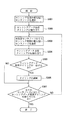
図3は、センサノード107〜109に対してセンシングデータ取得タイミングを割り当てる機能を有するスケジューリング部115による処理の流れを示すフローチャートである。
FIG. 3 is a flowchart showing a flow of processing by the
ステップS301において、スケジューリング部115は、センサノード情報記憶部116に格納されている複数のセンサノードのセンシング周期を互いに比較し、センシング周期が最も短いセンサノードを選択する。図2に示すようなセンシング周期がセンサノード情報記憶部116に格納されている場合、センサノード108のセンシング周期が最も短いため、スケジューリング部115は、センサノード108を選択する。
In step S301, the
ステップS302において、スケジューリング部115は、ステップS301にて選択したセンサノード108のセンシング周期に基づいて、センサノード108に対してセンシングデータ取得タイミングを割り当てる。すなわち、スケジューリング部115は、図4に示すように、センサノード108のスケジュールテーブルを作成する。
In step S302, the
図4は、スケジュールテーブルの一例を示す図である。
スケジューリング部115は、センサノード108に対して、図4(a)に示すように基準の時刻から5秒間隔でセンシングデータ取得タイミングが割り当てられたスケジュールテーブルを作成する。5秒間隔としたのは、センサノード108のセンシング周期が5秒であるからである(図2参照)。
FIG. 4 is a diagram illustrating an example of a schedule table.
The
ステップS303において、スケジューリング部115は、センシングデータ取得タイミングが未だ割り当てられていないセンサノードの中でセンシング周期が最も短いセンサノードを選択する。ステップS302ではセンサノード108に対するセンシングデータ取得タイミングが割り当てられているため、センサノード108以外のセンサノードであるセンサノード107とセンサノード109の中からセンシング周期が最も短いセンサノードを選択する。図2によると、センサノード108以外のセンサノードの中でセンシング周期が最も短いセンサノードはセンサノード109であるため、スケジューリング部115は、センサノード109を選択する。
In step S303, the
ステップS304において、スケジューリング部115は、センサノード109に対して、図4(b)に示すように、(基準の時刻+α)の時刻から6秒間隔でセンシングデータ取得タイミングが割り当てられたスケジュールテーブルを作成する。6秒間隔としたのは、センサノード109のセンシング周期が6秒であるからである(図2参照)。ステップS304にてセンサノード109に対して割り当てられたセンシングデータ取得タイミングは、後の処理で変更される場合があるため、ステップS304での割り当ては確定したものではない。よって、ステップS304での割り当てを「仮割り当て」という。
In step S304, the
ステップS305において、スケジューリング部115は、ステップS302とステップS304にて割り当てられたセンシングデータ取得タイミングが同一となることがあるか否かを検査し、同一タイミングとなることがある場合には、スケジューリング部115は、ステップS306の処理へ進み、同一タイミングとなることがない場合には、ステップS307の処理に進む。図4(b)に示すスケジュールテーブルによると、センサノード109に仮割り当てされたセンシングデータ取得タイミングと、センサノード108に割り当てられたセンシングデータ取得タイミングとが、t5のタイミングで一致している。したがって、スケジューリング部115は、ステップS306の処理へ進む。
In step S305, the
ステップS306において、スケジューリング部115は、上述のように複数のセンシングデータ取得タイミングが同一となるタイミング(本例では、t5)がある場合、センシング周期がより長い方のセンサノードに対するセンシングデータ取得タイミングを早めるか又は遅くするかして、両者のセンシングデータ取得タイミングが重ならないようにする。
In step S306, when there is a timing (in this example, t5) at which the plurality of sensing data acquisition timings are the same as described above, the
図4(c)に示したスケジュールテーブルよると、スケジューリング部115は、t5におけるセンシングデータ取得タイミングの重なりを解消するため、t5においてセンサノード109に仮割り当てされているセンシングデータ取得タイミングを所定時間だけ遅らせる。ここでいう所定時間は、例えば、センサノード108が1回分のセンシングデータをゲートウェイ装置101に送信するのに要する時間である。図2によると、センサノード108がゲートウェイ装置101に送信する1回分のセンシングデータのデータサイズは2KBである。したがって、スケジューリング部115は、センサノード109に対するセンシングデータ取得タイミングを、センサノード108が2Kバイトのセンシングデータをゲートウェイ装置101に送信するのに要する時間だけt5よりも遅らせる。ここで、センシングデータのデータサイズの代わりにセンシングデータのパケット数を用いて当該時間を求めてもよい。一方、これとは逆に、スケジューリング部115は、t5においてセンサノード109に仮割り当てされているセンシングデータ取得タイミングを所定時間だけ早めてもよい。ここでいう所定時間は、例えば、センサノード109が1回分のセンシングデータをゲートウェイ装置101に送信するのに要する時間である。図2によると、センサノード109がゲートウェイ装置101に送信する1回分のセンシングデータのデータサイズは1KBである。したがって、スケジューリング部115は、センサノード109に対するセンシングデータ取得タイミングを、センサノード109が1Kバイトのデータをゲートウェイ装置101に送信するのに要する時間だけt5よりも早めてもよい。このように、センサノードがゲートウェイ装置101に送信するのに1回分のセンシングデータのデータサイズ(又はパケット数)を予めセンサノード情報記憶部116に格納しておき、センシングデータ取得タイミングをそのデータサイズから求められるセンシングデータの送信時間分だけ遅らせるか、又は、早める。このことによって、複数のセンサノードが同時にセンシングデータのパケットをゲートウェイ装置101に送信しないように制御でき、ひいては、ネットワーク上でのパケット衝突を防止できる。
According to the schedule table shown in FIG. 4C, the
ステップS307において、スケジューリング部115は、全てのセンサノード107〜109に対してセンシングデータ取得タイミングが割り当てられているか否かを判定し、センシングデータ取得タイミングが未だ割り当てられていないセンサノードが有る場合にはステップS303の処理に進む一方、全てのセンサノード107〜109に対してセンシングデータ取得タイミングが割り当てられている場合には処理を終了する。つまり、スケジューリング部115は、センシングデータ取得タイミングが全てのセンサノード107〜109に対して割り当てられるまでステップS103〜ステップS306の処理を繰り返し実行する。上述した例では、センサノード108とセンサノード109に対するセンシングデータ取得タイミングの割り当ては確定しているが、センサノード107に対してはセンシングデータ取得タイミングが未だ割り当てられていない。したがって、スケジューリング部115は、センサノード107に対して、図4(d)に示すように、(基準の時刻+β)の時刻から10秒間隔でセンシングデータ取得タイミングが割り当てられたスケジュールテーブルを作成する。10秒間隔としたのは、センサノード107のセンシング周期が10秒であるからである(図2参照)。上述したように、この段階でセンサノード107に対して割り当てられたセンシングデータ取得タイミングは確定してはおらず、既に他のセンサノードに割り当てられたセンシングデータ取得タイミングとの関係で、ステップS306で示したようなタイミング調整が行われる可能性はある。こうして、全てのセンサノード107〜109に対するセンシングデータ取得タイミングの割り当てが確定すると、スケジューリング部115による処理は終了する。
In step S307, the
図4(d)に示したスケジュールテーブルは確定したものであり、ゲートウェイ装置101は、このスケジュールテーブルを参照して、センサノード108、109、107、108、109、108、107・・・という順番で各センサノードからセンシングデータを取得する。本スケジュールテーブルからわかるように、センシングデータ取得タイミングが一致する場合はないため、複数のセンサノードが同時に各々のセンシングデータのパケットをゲートウェイ装置101に送信することは起こらない。
The schedule table shown in FIG. 4D has been confirmed, and the
ゲートウェイ装置101の制御信号送受信部114は、スケジューリング部115が作成したスケジュールテーブルを参照して、制御信号としてセンシングデータ取得要求信号をセンサノードに送信し、このセンシングデータ取得要求を受けたセンサノードは、センシングデータをゲートウェイ装置101に送信する。これにより、ゲートウェイ装置101は、スケジュールテーブルに沿った適切なタイミングでセンシングデータを取得することができる。その他の構成として、センサノード107〜109との間で時刻同期を予めとっているゲートウェイ装置101が、スケジューリング部115により作成されたスケジュールテーブルを全てのセンサノード107〜109に送信し、各センサノードがこのスケジュールテーブルを参照して、自ノードに割り当てられたセンシングデータ取得タイミングにしたがって自律的にセンシングデータをゲートウェイ装置101に送信する構成であってもよい。
The control signal transmission /
新たなセンサノードが第2のネットワーク106に加わった場合、ゲートウェイ装置101のスケジューリング部115は、センサノードに対してセンシングデータ取得タイミングを割り当てる処理をやり直し、センサノードに対してセンシングデータ取得タイミングを再割り当てする。次いで、スケジューリング部115は、再割り当てしたセンシングデータ取得タイミングにしたがって、センサノードからセンシングデータを取得する。
When a new sensor node is added to the
スケジューリング部115は、センサノードがネットワークから切断した場合には、本来、センシングデータ取得タイミングを割り当てる処理をやり直す必要はない。しかし、センサノード109のように、アプリケーション要求周期がセンシング周期と同一であって、上述したようにセンサノード108との関係からセンシングデータ取得タイミングがt5から遅れたタイミングに割り当てられた場合には、センサノード108が切断されるとセンサノード109は本来のデータ取得タイミングであるt5に再割り当てされる。
When the sensor node is disconnected from the network, the
本実施の形態では、センシングデータを取得する前に予めスケジューリング部115がセンシングデータ取得タイミングをセンサノード毎に割り当てる構成をとるが、この構成以外に、センシングデータ取得時に、次回以降のセンシングデータ取得タイミングの割り当てる構成をとってもよい。
In this embodiment, a configuration is adopted in which the
また、本実施の形態では、第1のネットワーク105と第2のネットワーク106を異なるネットワークとして説明したが、これらを同一のネットワークとし、ゲートウェイ装置101をキャッシュサーバのように動作させる構成にしてもよい。
In the present embodiment, the
また、本実施の形態には、前述した一連の処理を実行するコンピュータプログラム及び当該コンピュータプログラムを記録したコンピュータ読み取り可能な記録媒体が含まれる。 Further, the present embodiment includes a computer program that executes the series of processes described above and a computer-readable recording medium that records the computer program.
101 ゲートウェイ装置、 102〜104 アプリケーションノード、 105 第1のネットワーク、 106 第2のネットワーク、 107〜109 センサノード、 110 センシングデータ送信部、 111 センサノード制御信号受信部、 112 センシングデータ・キャッシュ部、 113 センシングデータ受信部、 114 制御信号送受信部、 115 スケジューリング部、 116 センサノード情報記憶部。
DESCRIPTION OF
Claims (12)
前記センサノードに対応するセンシング周期を含むセンサノード情報を記憶する記憶手段と、
前記記憶手段から読み出した前記センシング周期に応じて、前記センサノードからセンシングデータを取得するタイミングを決定する決定手段と、
前記決定手段が決定したタイミングを前記センサノードの各々に対して割り当てる割り当て手段と、
前記割り当て手段が割り当てたタイミングで、前記ネットワークを介して、前記センサノードから前記センシングデータを取得する取得手段と、
を備え、
前記決定手段は、前記センシング周期を互いに比較し、センシング周期が短いセンサノードに対して優先的に前記タイミングを決定し、
前記割り当て手段は、前記センサノード毎に決定した前記タイミングが同一となる場合、センシング周期が長いセンサノードに対して、前記同一となるタイミングより遅いタイミング又は前記同一となるタイミングより早いタイミングを割り当てることを特徴とするゲートウェイ装置。 A gateway device connectable to a plurality of sensor nodes via a network,
Storage means for storing sensor node information including a sensing period corresponding to the sensor node;
Determining means for determining the timing for obtaining sensing data from the sensor node according to the sensing period read from the storage means;
Assigning means for assigning the timing determined by the determining means to each of the sensor nodes;
Obtaining means for obtaining the sensing data from the sensor node via the network at a timing assigned by the assigning means;
With
The determining means compares the sensing periods with each other, preferentially determines the timing with respect to a sensor node having a short sensing period,
The assigning means assigns a timing later than the same timing or earlier than the same timing to a sensor node having a long sensing cycle when the timing determined for each sensor node is the same. The gateway apparatus characterized by this.
前記タイミングは、前記センシング周期が短いセンサノードから取得するセンシングデータの前記データサイズ又は前記パケット数に基づいて定まることを特徴とする請求項1記載のゲートウェイ装置。 The sensor node information further includes the data size or the number of packets of sensing data corresponding to the sensor node,
The gateway apparatus according to claim 1, wherein the timing is determined based on the data size or the number of packets of sensing data acquired from a sensor node having a short sensing cycle.
前記タイミングは、前記センシング周期が長いセンサノードから取得するセンシングデータの前記データサイズ又は前記パケット数に基づいて定まることを特徴とする請求項1記載のゲートウェイ装置。 The sensor node information further includes the data size or the number of packets of sensing data corresponding to each of the sensor nodes,
The gateway device according to claim 1, wherein the timing is determined based on the data size or the number of packets of sensing data acquired from a sensor node having a long sensing cycle.
前記取得手段が取得したセンシングデータを、前記1つ又は複数のアプリケーションノードと接続可能なネットワークを介して、前記1つ又は複数のアプリケーションノードに送信する送信手段を更に備えることを特徴とする請求項1乃至3のいずれか1項に記載のゲートウェイ装置。 Further connectable to a network connectable to one or more application nodes;
The transmission apparatus according to claim 1, further comprising a transmission unit configured to transmit the sensing data acquired by the acquisition unit to the one or more application nodes via a network connectable to the one or more application nodes. The gateway device according to any one of 1 to 3.
前記ゲートウェイ装置は、
前記センサノードに対応するセンシング周期を含むセンサノード情報を記憶する記憶手段と、
前記記憶手段から読み出した前記センシング周期に応じて、前記センサノードからセンシングデータを取得するタイミングを決定する決定手段と、
前記決定手段が決定したタイミングを前記センサノードの各々に対して割り当てる割り当て手段と、
前記割り当て手段が割り当てたタイミングで、前記ネットワークを介して、前記センサノードから前記センシングデータを取得する取得手段と、
を備え、
前記決定手段は、前記センシング周期を互いに比較し、センシング周期が短いセンサノードに対して優先的に前記タイミングを決定し、
前記割り当て手段は、前記センサノード毎に決定した前記タイミングが同一となる場合、センシング周期が長いセンサノードに対して、前記同一となるタイミングより遅いタイミング又は前記同一となるタイミングより早いタイミングを割り当てることを特徴とするシステム。 A system comprising a plurality of sensor nodes, a network connectable to the plurality of sensor nodes, and a gateway device connectable to the network,
The gateway device is
Storage means for storing sensor node information including a sensing period corresponding to the sensor node;
Determining means for determining the timing for obtaining sensing data from the sensor node according to the sensing period read from the storage means;
Assigning means for assigning the timing determined by the determining means to each of the sensor nodes;
Obtaining means for obtaining the sensing data from the sensor node via the network at a timing assigned by the assigning means;
With
The determining means compares the sensing periods with each other, preferentially determines the timing with respect to a sensor node having a short sensing period,
The assigning means assigns a timing later than the same timing or earlier than the same timing to a sensor node having a long sensing cycle when the timing determined for each sensor node is the same. A system characterized by
前記ゲートウェイ装置は、
前記取得手段が取得したセンシングデータを、前記1つ又は複数のアプリケーションノードと接続可能なネットワークを介して、前記1つ又は複数のアプリケーションノードに送信する送信手段を更に備えることを特徴とする請求項5記載のシステム。 One or more application nodes and a network connectable to the one or more application nodes;
The gateway device is
The transmission apparatus according to claim 1, further comprising a transmission unit configured to transmit the sensing data acquired by the acquisition unit to the one or more application nodes via a network connectable to the one or more application nodes. 5. The system according to 5.
前記センサノードの各々に対応するセンシング周期を含むセンサノード情報を記憶手段に記憶する記憶ステップと、
前記記憶手段から読み出した前記センシング周期に応じて、前記センサノードからセンシングデータを取得するタイミングを決定する決定ステップと、
前記決定したタイミングを前記センサノードの各々に対して割り当てる割り当てステップと、
前記割り当てたタイミングで、前記ネットワークを介して、前記複数のセンサノードから前記センシングデータを取得する取得ステップと、
を含み、
前記決定ステップでは、前記センシング周期を互いに比較し、センシング周期が短いセンサノードに対して優先的に前記タイミングを決定し、
前記割り当てステップでは、前記センサノード毎に決定した前記タイミングが同一となる場合、センシング周期が長いセンサノードに対して、前記同一となるタイミングより遅いタイミング又は前記同一となるタイミングより早いタイミングを割り当てることを特徴とするゲートウェイ装置の制御方法。 A control method for a gateway device connectable to a plurality of sensor nodes via a network,
A storage step of storing in the storage means sensor node information including a sensing period corresponding to each of the sensor nodes;
A determination step for determining a timing for acquiring sensing data from the sensor node according to the sensing period read from the storage unit;
Assigning the determined timing to each of the sensor nodes;
An acquisition step of acquiring the sensing data from the plurality of sensor nodes via the network at the allocated timing;
Including
In the determining step, the sensing periods are compared with each other, and the timing is preferentially determined for a sensor node having a short sensing period,
In the assigning step, when the timing determined for each sensor node is the same, a timing later than the same timing or earlier than the same timing is assigned to a sensor node having a long sensing cycle. A control method of a gateway device characterized by the above.
前記タイミングは、前記センシング周期が短いセンサノードから取得するセンシングデータの前記データサイズ又は前記パケット数に基づいて定まることを特徴とする請求項7記載のゲートウェイ装置の制御方法。 The sensor node information further includes the data size or the number of packets of sensing data corresponding to each of the sensor nodes,
8. The gateway device control method according to claim 7, wherein the timing is determined based on the data size or the number of packets of sensing data acquired from a sensor node having a short sensing cycle.
前記タイミングは、前記センシング周期が長いセンサノードから取得するセンシングデータの前記データサイズ又は前記パケット数に基づいて定まることを特徴とする請求項7記載のゲートウェイ装置の制御方法。 The sensor node information further includes the data size or the number of packets of sensing data corresponding to each of the sensor nodes,
8. The gateway device control method according to claim 7, wherein the timing is determined based on the data size or the number of packets of sensing data acquired from a sensor node having a long sensing cycle.
前記取得ステップで取得したセンシングデータを、前記1つ又は複数のアプリケーションノードと接続可能なネットワークを介して、前記1つ又は複数のアプリケーションノードに送信するステップを更に含むことを特徴とする請求項7乃至9のいずれか1項に記載のゲートウェイ装置の制御方法。 A control method of a gateway device further connectable to a network connectable to one or a plurality of application nodes,
8. The method according to claim 7, further comprising transmitting the sensing data acquired in the acquiring step to the one or more application nodes via a network connectable to the one or more application nodes. The control method of the gateway apparatus of any one of thru | or 9.
Priority Applications (1)
| Application Number | Priority Date | Filing Date | Title |
|---|---|---|---|
| JP2009066331A JP5233770B2 (en) | 2009-03-18 | 2009-03-18 | GATEWAY DEVICE, ITS CONTROL METHOD, SYSTEM, PROGRAM FOR EXECUTING CONTROL METHOD, AND RECORDING MEDIUM CONTAINING THE PROGRAM |
Applications Claiming Priority (1)
| Application Number | Priority Date | Filing Date | Title |
|---|---|---|---|
| JP2009066331A JP5233770B2 (en) | 2009-03-18 | 2009-03-18 | GATEWAY DEVICE, ITS CONTROL METHOD, SYSTEM, PROGRAM FOR EXECUTING CONTROL METHOD, AND RECORDING MEDIUM CONTAINING THE PROGRAM |
Publications (2)
| Publication Number | Publication Date |
|---|---|
| JP2010220036A true JP2010220036A (en) | 2010-09-30 |
| JP5233770B2 JP5233770B2 (en) | 2013-07-10 |
Family
ID=42978359
Family Applications (1)
| Application Number | Title | Priority Date | Filing Date |
|---|---|---|---|
| JP2009066331A Active JP5233770B2 (en) | 2009-03-18 | 2009-03-18 | GATEWAY DEVICE, ITS CONTROL METHOD, SYSTEM, PROGRAM FOR EXECUTING CONTROL METHOD, AND RECORDING MEDIUM CONTAINING THE PROGRAM |
Country Status (1)
| Country | Link |
|---|---|
| JP (1) | JP5233770B2 (en) |
Cited By (11)
| Publication number | Priority date | Publication date | Assignee | Title |
|---|---|---|---|---|
| JP2012195722A (en) * | 2011-03-16 | 2012-10-11 | Ntt Docomo Inc | Wireless communication system, base station, wireless communication terminal, and access scheduling method |
| JP2013172179A (en) * | 2012-02-17 | 2013-09-02 | Kddi Corp | Gateway, sensor network system, and sensor control method and program |
| WO2013136604A1 (en) | 2012-03-15 | 2013-09-19 | オムロン株式会社 | Sensor module, sensor network system, data transmission method, data transmission program, and data collection method in sensor network system |
| JP2013543349A (en) * | 2010-11-01 | 2013-11-28 | インターデイジタル パテント ホールディングス インコーポレイテッド | Dynamic spectrum management |
| JPWO2013046468A1 (en) * | 2011-09-30 | 2015-03-26 | 富士通株式会社 | Wireless communication system, mobile station, base station, and wireless communication system control method |
| JP2015115062A (en) * | 2013-12-09 | 2015-06-22 | 財團法人資訊工業策進會 | Data integration device for use in sensor network; and data integration method thereof |
| JP2016135091A (en) * | 2015-01-19 | 2016-07-25 | エルエス産電株式会社Lsis Co., Ltd. | Data collection device of photovoltaic power generation system |
| GB2548663A (en) * | 2016-12-09 | 2017-09-27 | Polar Electro Oy | System for providing wrist device with cellular communication capability |
| CN107950005A (en) * | 2015-08-04 | 2018-04-20 | 康维达无线有限责任公司 | Service element Selection of chiller |
| JP2019161265A (en) * | 2018-03-07 | 2019-09-19 | 株式会社日立製作所 | Communication management method, communication system, and program |
| US11703425B2 (en) | 2020-11-05 | 2023-07-18 | Canon Kabushiki Kaisha | Information processing apparatus, system, production facility, information processing method, method of manufacturing products, and recording medium |
Citations (6)
| Publication number | Priority date | Publication date | Assignee | Title |
|---|---|---|---|---|
| JPH1153274A (en) * | 1997-08-01 | 1999-02-26 | Canon Inc | Communication control method |
| JP2000349815A (en) * | 1999-06-04 | 2000-12-15 | Fujitsu Ltd | Method for allocating band |
| JP2002157279A (en) * | 2000-11-22 | 2002-05-31 | Yokogawa Electric Corp | Data collecting device |
| JP2006187316A (en) * | 2004-12-28 | 2006-07-20 | Medical Electronic Science Inst Co Ltd | Remote sensing system and sensor unit |
| JP2007060400A (en) * | 2005-08-25 | 2007-03-08 | Auto Network Gijutsu Kenkyusho:Kk | Method and system for controlling communication timing |
| JP2007194942A (en) * | 2006-01-19 | 2007-08-02 | Ntt Docomo Inc | System and method for supporting sensor unit |
-
2009
- 2009-03-18 JP JP2009066331A patent/JP5233770B2/en active Active
Patent Citations (6)
| Publication number | Priority date | Publication date | Assignee | Title |
|---|---|---|---|---|
| JPH1153274A (en) * | 1997-08-01 | 1999-02-26 | Canon Inc | Communication control method |
| JP2000349815A (en) * | 1999-06-04 | 2000-12-15 | Fujitsu Ltd | Method for allocating band |
| JP2002157279A (en) * | 2000-11-22 | 2002-05-31 | Yokogawa Electric Corp | Data collecting device |
| JP2006187316A (en) * | 2004-12-28 | 2006-07-20 | Medical Electronic Science Inst Co Ltd | Remote sensing system and sensor unit |
| JP2007060400A (en) * | 2005-08-25 | 2007-03-08 | Auto Network Gijutsu Kenkyusho:Kk | Method and system for controlling communication timing |
| JP2007194942A (en) * | 2006-01-19 | 2007-08-02 | Ntt Docomo Inc | System and method for supporting sensor unit |
Cited By (20)
| Publication number | Priority date | Publication date | Assignee | Title |
|---|---|---|---|---|
| US9769692B2 (en) | 2010-11-01 | 2017-09-19 | Interdigital Patent Holdings, Inc. | Dynamic spectrum management |
| JP2013543349A (en) * | 2010-11-01 | 2013-11-28 | インターデイジタル パテント ホールディングス インコーポレイテッド | Dynamic spectrum management |
| JP2012195722A (en) * | 2011-03-16 | 2012-10-11 | Ntt Docomo Inc | Wireless communication system, base station, wireless communication terminal, and access scheduling method |
| JPWO2013046468A1 (en) * | 2011-09-30 | 2015-03-26 | 富士通株式会社 | Wireless communication system, mobile station, base station, and wireless communication system control method |
| US9408192B2 (en) | 2011-09-30 | 2016-08-02 | Fujitsu Limited | Radio communication system, mobile station, base station, and method for controlling radio communication system |
| JP2013172179A (en) * | 2012-02-17 | 2013-09-02 | Kddi Corp | Gateway, sensor network system, and sensor control method and program |
| WO2013136604A1 (en) | 2012-03-15 | 2013-09-19 | オムロン株式会社 | Sensor module, sensor network system, data transmission method, data transmission program, and data collection method in sensor network system |
| US9426740B2 (en) | 2012-03-15 | 2016-08-23 | Omron Corporation | Sensor module, sensor network system, data transmission method, data transmission program, and data collection method in sensor network system |
| JP2015115062A (en) * | 2013-12-09 | 2015-06-22 | 財團法人資訊工業策進會 | Data integration device for use in sensor network; and data integration method thereof |
| US10091273B2 (en) | 2015-01-19 | 2018-10-02 | Lsis Co., Ltd. | Data collecting device for photovoltaic device |
| JP2016135091A (en) * | 2015-01-19 | 2016-07-25 | エルエス産電株式会社Lsis Co., Ltd. | Data collection device of photovoltaic power generation system |
| CN107950005A (en) * | 2015-08-04 | 2018-04-20 | 康维达无线有限责任公司 | Service element Selection of chiller |
| JP2018523873A (en) * | 2015-08-04 | 2018-08-23 | コンヴィーダ ワイヤレス, エルエルシー | Service element host selection |
| CN107950005B (en) * | 2015-08-04 | 2021-09-14 | 康维达无线有限责任公司 | Service element host selection |
| GB2548663A (en) * | 2016-12-09 | 2017-09-27 | Polar Electro Oy | System for providing wrist device with cellular communication capability |
| US9967916B1 (en) | 2016-12-09 | 2018-05-08 | Polar Electro Oy | System for providing wrist device with cellular communication capability |
| GB2548663B (en) * | 2016-12-09 | 2018-05-09 | Polar Electro Oy | System for providing wrist device with cellular communication capability |
| JP2019161265A (en) * | 2018-03-07 | 2019-09-19 | 株式会社日立製作所 | Communication management method, communication system, and program |
| JP7289614B2 (en) | 2018-03-07 | 2023-06-12 | 株式会社日立製作所 | Communication management method, communication system and program |
| US11703425B2 (en) | 2020-11-05 | 2023-07-18 | Canon Kabushiki Kaisha | Information processing apparatus, system, production facility, information processing method, method of manufacturing products, and recording medium |
Also Published As
| Publication number | Publication date |
|---|---|
| JP5233770B2 (en) | 2013-07-10 |
Similar Documents
| Publication | Publication Date | Title |
|---|---|---|
| JP5233770B2 (en) | GATEWAY DEVICE, ITS CONTROL METHOD, SYSTEM, PROGRAM FOR EXECUTING CONTROL METHOD, AND RECORDING MEDIUM CONTAINING THE PROGRAM | |
| KR101317178B1 (en) | ZigBee Gateway and method for identifying message of the same | |
| CN103929377A (en) | Wired network and wireless network combined dispatching method and system and related devices | |
| JP2009003677A (en) | Usb host, usb slave, wireless communication system, and data transfer method | |
| JP7394185B2 (en) | Communications system | |
| JP2006295907A (en) | Wireless sensor network system, base station, wireless sensor and program | |
| JP2022088481A (en) | Communication device, communication system, device control system, communication control method, and program | |
| KR20190025509A (en) | Communication system, lighting control system, and communication device | |
| TWI536782B (en) | Methods and devices for connecting to multiple interfaces | |
| KR101601303B1 (en) | Method for mediating message with differed typed protocol | |
| JP4493606B2 (en) | Data transmission method and data transmission system by cyclic communication | |
| KR101748080B1 (en) | System and method for transmitting and receiving data based on can-bus for marine iot platform | |
| JP7042438B2 (en) | Communication equipment, communication systems, and lighting control systems | |
| TW201924238A (en) | Communication system, apparatus control system, communication device, communication control method, and program capable of easily realizing cooperation among a plurality of second systems | |
| US9647976B2 (en) | Method and device for implementing end-to-end hardware message passing | |
| WO2018122893A1 (en) | Data access system and data access method | |
| US11489697B2 (en) | Transmission of data on a local bus | |
| US20160006802A1 (en) | Data sharing system | |
| KR102049690B1 (en) | Things control system using private lora network with virtual device function | |
| JP7065339B2 (en) | Communication devices, communication interfaces, communication systems, device control systems, communication control methods and programs | |
| JP2010124138A (en) | Cyclic transmission system and its transmission method | |
| CN106170022B (en) | Distributed multimedia sensor control system | |
| JP2023018732A (en) | Communication system and communication device | |
| WO2017183386A1 (en) | Information processing device, information processing method and program | |
| JP5994475B2 (en) | Communication device |
Legal Events
| Date | Code | Title | Description |
|---|---|---|---|
| A621 | Written request for application examination |
Free format text: JAPANESE INTERMEDIATE CODE: A621 Effective date: 20111115 |
|
| A977 | Report on retrieval |
Free format text: JAPANESE INTERMEDIATE CODE: A971007 Effective date: 20130208 |
|
| TRDD | Decision of grant or rejection written | ||
| A01 | Written decision to grant a patent or to grant a registration (utility model) |
Free format text: JAPANESE INTERMEDIATE CODE: A01 Effective date: 20130226 |
|
| A61 | First payment of annual fees (during grant procedure) |
Free format text: JAPANESE INTERMEDIATE CODE: A61 Effective date: 20130311 |
|
| R150 | Certificate of patent or registration of utility model |
Free format text: JAPANESE INTERMEDIATE CODE: R150 Ref document number: 5233770 Country of ref document: JP Free format text: JAPANESE INTERMEDIATE CODE: R150 |
|
| FPAY | Renewal fee payment (event date is renewal date of database) |
Free format text: PAYMENT UNTIL: 20160405 Year of fee payment: 3 |