JP2010171009A - Operation device for electric appliance - Google Patents
Operation device for electric appliance Download PDFInfo
- Publication number
- JP2010171009A JP2010171009A JP2010003563A JP2010003563A JP2010171009A JP 2010171009 A JP2010171009 A JP 2010171009A JP 2010003563 A JP2010003563 A JP 2010003563A JP 2010003563 A JP2010003563 A JP 2010003563A JP 2010171009 A JP2010171009 A JP 2010171009A
- Authority
- JP
- Japan
- Prior art keywords
- sensitive switch
- control panel
- operating device
- touch
- operating
- Prior art date
- Legal status (The legal status is an assumption and is not a legal conclusion. Google has not performed a legal analysis and makes no representation as to the accuracy of the status listed.)
- Granted
Links
Images


Classifications
-
- H—ELECTRICITY
- H03—ELECTRONIC CIRCUITRY
- H03K—PULSE TECHNIQUE
- H03K17/00—Electronic switching or gating, i.e. not by contact-making and –breaking
- H03K17/94—Electronic switching or gating, i.e. not by contact-making and –breaking characterised by the way in which the control signals are generated
- H03K17/96—Touch switches
- H03K17/962—Capacitive touch switches
-
- H—ELECTRICITY
- H01—ELECTRIC ELEMENTS
- H01H—ELECTRIC SWITCHES; RELAYS; SELECTORS; EMERGENCY PROTECTIVE DEVICES
- H01H3/00—Mechanisms for operating contacts
- H01H3/02—Operating parts, i.e. for operating driving mechanism by a mechanical force external to the switch
- H01H3/08—Turn knobs
-
- H—ELECTRICITY
- H03—ELECTRONIC CIRCUITRY
- H03K—PULSE TECHNIQUE
- H03K17/00—Electronic switching or gating, i.e. not by contact-making and –breaking
- H03K17/94—Electronic switching or gating, i.e. not by contact-making and –breaking characterised by the way in which the control signals are generated
- H03K17/965—Switches controlled by moving an element forming part of the switch
-
- H—ELECTRICITY
- H01—ELECTRIC ELEMENTS
- H01H—ELECTRIC SWITCHES; RELAYS; SELECTORS; EMERGENCY PROTECTIVE DEVICES
- H01H3/00—Mechanisms for operating contacts
- H01H3/02—Operating parts, i.e. for operating driving mechanism by a mechanical force external to the switch
- H01H2003/0293—Operating parts, i.e. for operating driving mechanism by a mechanical force external to the switch with an integrated touch switch
-
- H—ELECTRICITY
- H01—ELECTRIC ELEMENTS
- H01H—ELECTRIC SWITCHES; RELAYS; SELECTORS; EMERGENCY PROTECTIVE DEVICES
- H01H3/00—Mechanisms for operating contacts
- H01H3/02—Operating parts, i.e. for operating driving mechanism by a mechanical force external to the switch
- H01H3/08—Turn knobs
- H01H2003/085—Retractable turn knobs, e.g. flush mounted
-
- H—ELECTRICITY
- H01—ELECTRIC ELEMENTS
- H01H—ELECTRIC SWITCHES; RELAYS; SELECTORS; EMERGENCY PROTECTIVE DEVICES
- H01H2221/00—Actuators
- H01H2221/008—Actuators other then push button
- H01H2221/01—Actuators other then push button also rotatable
-
- H—ELECTRICITY
- H01—ELECTRIC ELEMENTS
- H01H—ELECTRIC SWITCHES; RELAYS; SELECTORS; EMERGENCY PROTECTIVE DEVICES
- H01H2239/00—Miscellaneous
- H01H2239/006—Containing a capacitive switch or usable as such
Landscapes
- Switches That Are Operated By Magnetic Or Electric Fields (AREA)
- Rotary Switch, Piano Key Switch, And Lever Switch (AREA)
- Switch Cases, Indication, And Locking (AREA)
- Mechanisms For Operating Contacts (AREA)
- Input From Keyboards Or The Like (AREA)
- Electronic Switches (AREA)
- Cookers (AREA)
Abstract
Description
本発明は、制御パネルと、前記制御パネルに配置された回転作動操作用の操作要素とを有する電化製品用の操作装置であって、前記操作要素が、カップ状の収容部に取り付けられ、少なくとも1つの追加のタッチセンシティブスイッチが、前記操作要素に近接したまたは前記操作要素の周囲の前記制御パネルの領域に配置される操作装置に関する。 The present invention is an operation device for an electrical appliance having a control panel and an operation element for rotational operation disposed on the control panel, wherein the operation element is attached to a cup-shaped container, and at least One additional touch-sensitive switch relates to an operating device arranged in the area of the control panel close to or around the operating element.
このような操作装置は多くのおよび多様な形態で知られている。このような場合、収容部は、例えば特許文献1から知られているように、最も頻繁には、例えば回転ノブ等の操作要素が取り付けられる制御パネルにまたはその後部に配置される。さらに、この回転ノブは後退可能であり得る。収容部の後部には、回転ノブによって操作される回転スイッチ装置が配置される。このような回転作動に加えて、操作装置により別の機能を起動することが可能であることが望ましいかもしれない。例えば、補助スイッチ等を設けることが可能である。回転ノブ自体でこのような補助スイッチを構成するための1つの方法が、例えば特許文献2から知られている。 Such operating devices are known in many and various forms. In such a case, as is known from, for example, Patent Document 1, the housing portion is most frequently arranged on the control panel to which an operation element such as a rotary knob is attached or on the rear portion thereof. Furthermore, the rotary knob may be retractable. A rotary switch device operated by a rotary knob is disposed at the rear of the housing portion. In addition to such rotational actuation, it may be desirable to be able to activate another function with the operating device. For example, an auxiliary switch or the like can be provided. One method for configuring such an auxiliary switch with the rotary knob itself is known, for example, from US Pat.
本発明の課題は、別の機能を備えかつ有利には操作装置の操作機能を向上させることが可能である上記操作装置を提供することである。 The object of the present invention is to provide an operating device which has other functions and which can advantageously improve the operating function of the operating device.
この課題は、請求項1の特徴を有する操作装置によって解決される。本発明の有利かつ好ましい形態は、別の請求項の主題であり、以下により詳細に説明される。請求項の用語は、明確な参照によって明細書の記載内容に援用される。 This problem is solved by an operating device having the features of claim 1. Advantageous and preferred forms of the invention are the subject matter of the other claims and are described in more detail below. The terminology in the claims is hereby incorporated by reference into the written description.
操作装置が、回転作動操作用の操作要素、特に回転ノブを備えることが意図され得る。操作要素は、制御パネルに配置され、ここで、カップ状の収容部に取り付けられる。本発明によれば、少なくとも1つの追加のタッチセンシティブスイッチは、操作要素に近接したまたはその周囲の制御パネルの領域に設けられる。特に、このタッチセンシティブスイッチは、操作要素に直接隣接するか、または適切な狭い間隙によって操作要素から単に分離される。 It may be intended that the operating device comprises an operating element for rotational actuation operation, in particular a rotary knob. The operating element is arranged on the control panel, where it is attached to a cup-shaped housing. According to the invention, at least one additional touch-sensitive switch is provided in the area of the control panel close to or around the operating element. In particular, this touch-sensitive switch is directly adjacent to the operating element or simply separated from the operating element by a suitable narrow gap.
このようにして、例えば、回転可能な操作要素によって、出力設定または出力時間を調整することが可能であり、すなわち、数値を変化させることが可能である。ここで、これらのことが、調整が終了した場合に適用されるか、またはその代わりに、追加のタッチセンシティブスイッチによって、信号を作動信号として正確に生成し得る。さらに、回転作動は、例えば操作要素の設定マークによる、操作要素の周囲のリングに配置された複数のタッチセンシティブスイッチの1つへの空間の割り当てを保証することが可能であり、次に、前記空間の割り当てが作動信号として作動される。操作方法に関する多数の別の選択が提供され、容易に考えられる。 In this way, it is possible, for example, to adjust the output setting or the output time by means of a rotatable operating element, ie it is possible to change the numerical value. Here, these can be applied when the adjustment is finished, or alternatively, an additional touch-sensitive switch can accurately generate the signal as an activation signal. Furthermore, the rotational actuation can ensure the allocation of space to one of a plurality of touch-sensitive switches arranged in a ring around the operating element, for example by means of setting marks on the operating element, Space allocation is activated as an activation signal. Numerous alternative choices regarding the method of operation are provided and are readily contemplated.
本発明の一形態では、タッチセンシティブスイッチは、有利には、容量式のタッチセンシティブスイッチであり得る。このため、そのスイッチは、容量式の導電性センサ素子を備えることが可能である。このセンサ素子は、特に有利には、前記センサ素子が配置される制御パネルの外面でまたは前面で電気的に絶縁される。したがって、このことは、上記センサ素子が、操作者の接触に関して電気的に絶縁され、したがって、安全規則も守られることを意味する。 In one form of the invention, the touch-sensitive switch can advantageously be a capacitive touch-sensitive switch. For this reason, the switch can be provided with a capacitive conductive sensor element. This sensor element is particularly advantageously electrically insulated at the outer or front surface of the control panel on which the sensor element is arranged. This therefore means that the sensor element is electrically isolated with respect to operator contact and therefore safety regulations are also observed.
本発明の別の発展形態では、収容部は、制御パネルにほぼ平行におよび操作要素の周囲に延びるカラー状の部分を備え得る。タッチセンシティブスイッチ、またはそれ用のセンサ素子を、このカラー状の部分に配置し、例えばそれに取り付けることが可能である。このことについて以下により詳細に説明する。特に、収容部のカラー状の部分がタッチセンシティブスイッチまたはセンサ素子を覆うことが意図され得る。ここで、上記電気絶縁も非常に容易に実現することが可能である。次に、複雑な作業をパネルで行う必要がないように、あるいは操作装置を変更することによって、同じパネルで設計および/または操作機能を変更し得るように、タッチセンシティブスイッチの接触面が収容部の部分によって形成される。 In another development of the invention, the receiving part may comprise a collar-like part extending substantially parallel to the control panel and around the operating element. A touch-sensitive switch, or sensor element therefor, can be arranged in this collar-like part, for example attached to it. This will be described in more detail below. In particular, it may be intended that the collar-shaped part of the housing covers the touch sensitive switch or sensor element. Here, the electrical insulation can also be realized very easily. Next, the touch sensitive switch contact surface is received by the housing so that complex work does not need to be performed on the panel or the design and / or operating functions can be changed on the same panel by changing the operating device. Formed by the parts.
本発明の一形態では、有利には平坦な構造であるセンサ素子をコーティングとして製造することが可能である。導電性材料のこのようなコーティングは、有利には、制御パネルに平行に延びる収容部の領域に設けることが可能である。特に、上記領域は上記カラー状の部分であり、ここで、この部分の後部には、対応するコーティングによってセンサ素子が付与される。 In one form of the invention, it is possible to produce a sensor element which is advantageously a flat structure as a coating. Such a coating of conductive material can advantageously be provided in the area of the receiving part extending parallel to the control panel. In particular, the region is the collar-like part, where the sensor element is applied to the rear part of this part by a corresponding coating.
本発明の代替形態では、センサ素子が、平坦な材料から製造され、有利には平坦な金属板として製造されることが意図され得る。このような金属板は、別個の部分として制御パネル自体または収容部に取り付けることが可能であり、例えば接着接合することが可能である。この場合も、1つの適切な方法は、上記センサ素子が、コーティングと同様に、別個の部分として収容部または上記カラー状の部分に取り付けられる方法である。これにより、センサ素子が、正確に所定の空間の割り当てで操作装置に配置されることも保証される。 In an alternative form of the invention, it may be intended that the sensor element is manufactured from a flat material, advantageously as a flat metal plate. Such a metal plate can be attached as a separate part to the control panel itself or to the housing, for example, by adhesive bonding. Again, one suitable method is that the sensor element is attached as a separate part to the receiving part or the collar-like part, similar to the coating. This also ensures that the sensor elements are arranged in the operating device with a precisely predetermined space allocation.
本発明の別形態では、タッチセンシティブスイッチへのまたはそれらのセンサ素子への電源リードまたは電源コネクタを収容部に一体化し得る。また、このため、収容部は、制御パネルの後部に配置され、例えば、操作要素を用いた回転作動によって作動可能なスイッチ装置を備え、このスイッチ装置は収容部の後端に取り付けられる。 In another form of the invention, a power lead or power connector to the touch sensitive switch or to their sensor elements may be integrated into the receptacle. For this reason, the accommodating portion is disposed at the rear portion of the control panel, and includes, for example, a switch device that can be operated by a rotation operation using an operation element, and this switch device is attached to the rear end of the accommodating portion.
電源リードまたは電源コネクタが導電性コーティングとして収容部の表面に設けられるように、前記電源リードまたは前記電源コネクタを収容部に一体化することが可能である。このことは、特に有利には収容部の外側で可能である。厚層ペースト等によって、またはその代わりにプラスチックによって、コーティングを設けることが可能であり、導電性のために、前記コーティングには、粒子が混合される。コーティングの代わりに、例えば非常に薄い銅片からなりかつ収容部に接着接合される非常に薄い導電体によって、電源リードまたは電源コネクタを実現してもよい。その代わりに、本発明のさらに別の形態として、電源リードまたは電源コネクタを、ある種の導体ワイヤ等として、従来通りにプラスチックからなる収容部に射出成形してもよい。さらに、2構成要素射出成形により、導電性プラスチックを電源リードとして射出成形することが可能である。 It is possible to integrate the power supply lead or the power supply connector into the housing portion so that the power supply lead or the power connector is provided as a conductive coating on the surface of the housing portion. This is particularly preferably possible outside the housing. It is possible to provide a coating, such as by thick layer paste or the like, or alternatively by plastic, and for conductivity, particles are mixed into the coating. Instead of a coating, the power lead or power connector may be realized by a very thin conductor, for example made of a very thin piece of copper and adhesively bonded to the receptacle. Instead, as another embodiment of the present invention, the power supply lead or the power supply connector may be injection-molded in a conventional plastic housing as a kind of conductor wire or the like. Further, by two-component injection molding, the conductive plastic can be injection molded as a power lead.
一般に、MID(成形された相互接続装置)技術を用いて、センサ素子および電源リードまたは電源接続部の両方を利用することも可能である。これは、導体配置が、この場合、構造化された金属層の形状の収容部等の3次元形状の支持部に利用される新規な方法である。 In general, it is also possible to utilize both sensor elements and power leads or power connections using MID (Molded Interconnect Device) technology. This is a novel method in which the conductor arrangement is used in this case for a three-dimensional shaped support such as a structured metal layer shaped receptacle.
コーティングの形状の電源リードの場合、この電源リードが、収容部の外側で上記カラー状の部分に案内され、その部分にわたって延びることが意図され得る。このようなコーティング自体は、広く適用される場合に、「容量式の」センサ素子を形成することが可能である。代わりに、電気接続のために、金属板の形状のセンサ素子を特に上記コーティングに配置し、特に導電性接着剤で適切に接着接合してもよい。ここで、上記センサ素子は、例えば薄い銅板等の上記適用された薄い導体に対応する。 In the case of a power lead in the form of a coating, it can be intended that this power lead is guided to the collar-like part outside the receptacle and extends over that part. Such coatings themselves can form “capacitive” sensor elements when widely applied. Alternatively, for electrical connection, a sensor element in the form of a metal plate may be placed in particular on the coating and suitably adhesively bonded, in particular with a conductive adhesive. Here, the sensor element corresponds to the applied thin conductor such as a thin copper plate.
有利には、上記電源リードまたは電源コネクタによって、収容部の後端に配置されたスイッチ装置に電気接続部が設けられる。このようにして、例えば、スイッチ装置自体への電気接続部のように、タッチセンシティブスイッチ用の電気接続部をスイッチ装置に設けることが可能である。したがって、例えば、プラグ群等のような同一のプラグを使用することが可能である。ここで、常に電気接続部を非常に迅速かつ明確に認識することができる。代わりに、電気接続部を形成するように、別個のケーブルを電源リードまたは電源コネクタから案内してもよい。 Advantageously, the power lead or the power connector provides an electrical connection to the switch device arranged at the rear end of the housing. In this way, it is possible to provide the switch device with an electrical connection for a touch sensitive switch, such as an electrical connection to the switch device itself. Therefore, for example, it is possible to use the same plug such as a plug group. Here, the electrical connection can always be recognized very quickly and clearly. Alternatively, a separate cable may be guided from the power lead or power connector to form an electrical connection.
本発明の有利な別の発展形態では、上述されているように、複数の追加のタッチセンシティブスイッチが制御パネルに設けられ、操作要素の周囲に分配される。上記タッチセンシティブスイッチは、特に有利には、大きさが同一であり、均一に分配することが可能である。この場合有利には、別個の電源リードまたは電源コネクタに、別個の各タッチセンシティブスイッチまたはその上記センサ素子用の別個の電気端子が設けられることが意図される。このようにして、例えば、4個から12個のこのようなセンサ素子を設けることが可能である。 In an advantageous further development of the invention, as described above, a plurality of additional touch-sensitive switches are provided on the control panel and distributed around the operating elements. The touch-sensitive switches are particularly advantageously of the same size and can be distributed uniformly. In this case, it is advantageously intended that a separate power lead or power connector is provided with a separate electrical terminal for each separate touch-sensitive switch or its sensor element. In this way, for example, 4 to 12 such sensor elements can be provided.
本発明の別形態では、表示器を操作要素の周囲の制御パネルに設け得る。この表示器は、例えば、それぞれ別々に作動することも可能であるLED表示器またはOLED表示器であり得る。このような表示器の電気的な作動は、上記タッチセンシティブスイッチまたはセンサ素子のために同様の方法で行うことが可能である。 In another form of the invention, a display can be provided on the control panel around the operating element. This indicator can be, for example, an LED indicator or an OLED indicator, each of which can be operated separately. The electrical actuation of such a display can be performed in a similar manner for the touch sensitive switch or sensor element.
これらおよび別の特徴は、請求項からだけでなく、説明および図面からも明らかになり、個々の特徴は、本発明の実施形態のサブコンビネーションの形態においておよび他の分野において、それぞれ単独でまたは複数の組み合わせで実現され、本明細書で保護が請求される有利でそれ自体保護可能な実施形態を表すことが可能である。本出願が個々の区分および副題に細分されても、以下になされる説明の一般的な適用性が制限されない。 These and other features will become apparent not only from the claims but also from the description and drawings, and individual features may be singularly or plurally in the form of subcombinations of embodiments of the invention and in other fields, respectively. It is possible to represent advantageous and per se protectable embodiments which are realized in combination and are claimed herein for protection. Subdividing this application into individual sections and subtitles does not limit the general applicability of the description made below.
本発明の例示的な実施形態を図面に概略的に示し、以下により詳細に説明する。 Exemplary embodiments of the invention are schematically illustrated in the drawings and are described in more detail below.
図1は、図2の部分B−Bによれば、操作装置11が面一に設置されるカットアウト13において、より詳細には図示していない電化製品の制御パネル12に取り付けられる本発明による操作装置11を示している。回転作動のために、上記操作装置は、前方把持部16と、軸受構造として構成された基部17とからなる回転ノブ15を備える。回転ノブ15が、後退する回転ノブの形態をとるように、把持部16と基部17とが接続される。このことは、例えば、特許文献1から知られており、ここで、さらなる説明を行うことを不要にするために、特許文献1を明確に参照されたい。
1 according to the invention, according to part BB of FIG. 2, in a
回転ノブ15は収容カップ19に延び、この収容カップは、有利には管状部の形状の外側シェル20と、それに直接接続された内側シェル23とを備える。回転ノブ15の把持部16は、後退時に、内側シェル23と外側シェル20との間の中間空間に係合し得る。外側シェル20は、前部においてカラー状の部分24に展開し、その部分24は外側シェル20の長手方向延長部に対してほぼ垂直に突出する。このことは、図2の平面図からも非常に明確に理解することが可能である。
The
収容カップ19の後端26には、回転ノブ15によって調整し得る回転スイッチ装置28が設けられる。このため、上記回転スイッチ装置は、収容カップ19の後端26に取り付けられる軸スタブ30を介して基部17に接続される。
A
タッチセンシティブスイッチ32は、特に図2に示したように、制御パネル12の前部またはその上に設けられ、12個の部材が回転ノブ15の周囲に環状に分配される。タッチセンシティブスイッチ32は、分離ウェブによって互いに明確に画定される。上記タッチセンシティブスイッチは、容量式のタッチセンシティブスイッチの形態をとり、このため、容量式のセンサ素子34を備える。図1の左側において、容量式のセンサ素子34は、対応して形成された金属板として構成され、カラー状の部分24の反対方向に向いた側面に取り付けられ、特に確実に接着接合される。センサ素子34の電気的接触のために、電源リード36が設けられ、この電源リードは、導電性コーティングとして、外側シェル20の、または接着接合されたウェブ形状の導体材料の外側に取り付けられる。電源リード36は、センサ素子34の輪郭に沿ってカラー状の部分24の後面全体を覆い、それに当接するかまたはそれに電気的に接続される。次に、電源リード36は、常に外側シェル20の外面において、後端26に向かって延びる。例えば、導電性接着剤で接着接合された接触手段38、およびケーブル等によって、上記電源リードが、回転スイッチ装置28の底部の端子プラグ40に連結されるかまたはそれに接続される。対応して適切なプラグコネクタへの差し込みによって、容量式のセンサ素子34を作動させることができ、評価することができる。
As shown in FIG. 2 in particular, the touch
容量的に動作するタッチセンシティブスイッチの代わりに、小型の反射光バリアを使用して、ユーザの指の当たりを検出してもよい。ここで、上記反射光バリアは、センサ素子34の代わりに、カラー状の部分24の下部に配置され、対応する電気接続部によって作動されるが、この場合、その接続部は著しく複雑である。
Instead of a capacitively operated touch-sensitive switch, a small reflective light barrier may be used to detect a user's finger hit. Here, instead of the
図1の右側には、代替形態が示されている。図1の右側にも、タッチセンシティブスイッチ32が設けられ、このスイッチを作動させるために、操作者はタッチセンシティブスイッチ32またはこの箇所のカラー状の部分24の頂部に自分の指を当てる。この場合、容量式のセンサ素子34’はカラー状の部分24の底部に設けられ、このセンサ素子は、コーティングの形態をとり、センサ素子34のような別個の部分を有しない。このコーティングは電源リード36’に直接接続され、この電源リードは、上記のように、一方がコーティングであり、他方が別個の導体であり得る。収容カップ19の収容部の後端26の前の短い距離において、電源リード36’には、ケーブル39を介して端子プラグ40に通じる接触手段38’が設けられる。したがって、この場合、端子プラグ40は回転スイッチ装置28に設けられない。
An alternative form is shown on the right side of FIG. A touch
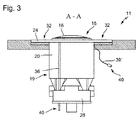
図2による部分A−Aである図3の別の図面から、例えば、図1の断面図に示した電源リード36が、どの程度の幅であり得るか、および外側シェル20の外側にわたってどのように延びるかが明らかである。ここで、上記電源リードは回転スイッチ装置28の底部で端子プラグ40に展開する。
From another view of FIG. 3 which is part AA according to FIG. 2, for example, how wide the
さらに、図3は、単なる代替例として、ケーブル39’を介した容量式のタッチセンシティブスイッチ32のセンサ素子34への概略的な接続を示している。特に、このような別個のまたは自由なケーブルの場合、全てのセンサ素子34のために、単一のマルチプラグイン接続部を設けることが可能であり得る。
Furthermore, FIG. 3 shows, as an alternative only, a schematic connection of the capacitive touch-
本発明の別形態では、同じ出願人によって同じ優先日に出願された同時出願の特許文献3から知られているように、収容カップ19、特に外側シェル20が少なくとも部分的に光伝導性材料からなることが可能である。例えば、LEDによる後方から回転スイッチ装置28への光照射の場合、カラー状の部分24の前面で照明効果を得ることが可能である。
In another form of the invention, as is known from co-pending US Pat. No. 6,057,053 filed on the same priority date by the same applicant, the receiving
例えば印刷工程、特にパッド印刷によって、収容カップ19の導電性コーティングをカラー状の部分24の後部または外側シェル20の外側に向かって延ばすことが可能である。
It is possible to extend the conductive coating of the receiving
また、隣接する2つのセンサ素子を作動させることによって、指を当てたときの容量オーバーカップリングを検出し得ることが図2から明らかである。これは代替的な容量検出方法である。 Also, it is clear from FIG. 2 that capacitive overcoupling when a finger is applied can be detected by operating two adjacent sensor elements. This is an alternative capacity detection method.
11 操作装置
12 制御パネル
13 カットアウト
15 回転ノブ
16 前方把持部
17 基部
19 収容カップ
20 外側シェル
23 内側シェル
24 カラー状の部分
26 収容カップ19の後端
28 回転スイッチ装置
30 軸スタブ
32 タッチセンシティブスイッチ
34 容量式のセンサ素子
34’ 容量式のセンサ素子
36 電源リード
36’ 電源リード
38 接触手段
38’ 接触手段
39 ケーブル
39’ ケーブル
40 端子プラグ
DESCRIPTION OF
Claims (13)
Applications Claiming Priority (2)
| Application Number | Priority Date | Filing Date | Title |
|---|---|---|---|
| DE102009006421.4 | 2009-01-22 | ||
| DE102009006421A DE102009006421A1 (en) | 2009-01-22 | 2009-01-22 | Operating device for an electrical appliance |
Publications (2)
| Publication Number | Publication Date |
|---|---|
| JP2010171009A true JP2010171009A (en) | 2010-08-05 |
| JP5615560B2 JP5615560B2 (en) | 2014-10-29 |
Family
ID=42153836
Family Applications (1)
| Application Number | Title | Priority Date | Filing Date |
|---|---|---|---|
| JP2010003563A Expired - Fee Related JP5615560B2 (en) | 2009-01-22 | 2010-01-12 | Operation device for electrical appliances |
Country Status (7)
| Country | Link |
|---|---|
| US (1) | US8217292B2 (en) |
| EP (1) | EP2211465B1 (en) |
| JP (1) | JP5615560B2 (en) |
| CN (1) | CN101794160B (en) |
| DE (1) | DE102009006421A1 (en) |
| ES (1) | ES2400035T3 (en) |
| SI (1) | SI2211465T1 (en) |
Families Citing this family (7)
| Publication number | Priority date | Publication date | Assignee | Title |
|---|---|---|---|---|
| US8503169B2 (en) * | 2009-02-18 | 2013-08-06 | American Trim, L.L.C. | Appliance control panel |
| IT1404166B1 (en) * | 2011-02-04 | 2013-11-15 | Whirlpool Co | CONCEALED COMMAND DEVICE FOR HOUSEHOLD APPLIANCES |
| US9063623B2 (en) | 2011-12-01 | 2015-06-23 | Green Cedar Holdings Llc | Capacitive touch sensor assembly for use in a wet environment |
| ES2454872A1 (en) * | 2012-10-11 | 2014-04-11 | BSH Electrodomésticos España S.A. | Operating device a gas-heated cooking device |
| KR20150120120A (en) * | 2014-04-17 | 2015-10-27 | 삼성전자주식회사 | Rotary knob assembly capable of moving up and down |
| EP3547303B1 (en) * | 2018-03-29 | 2020-05-13 | Ableton AG | Key with enhanced expressive possibilities |
| JP7435083B2 (en) * | 2020-03-16 | 2024-02-21 | ヤマハ株式会社 | Rotary operation device |
Citations (4)
| Publication number | Priority date | Publication date | Assignee | Title |
|---|---|---|---|---|
| JPS58177903U (en) * | 1982-05-21 | 1983-11-28 | 三菱電機株式会社 | Waterproof structure of operating shaft |
| JPH0741542U (en) * | 1993-12-27 | 1995-07-21 | 旭光学工業株式会社 | Adjustment dial |
| JP2004311196A (en) * | 2003-04-07 | 2004-11-04 | Alps Electric Co Ltd | Input device |
| JP2007073506A (en) * | 2005-09-02 | 2007-03-22 | Valeo Systemes Thermiques | Button device for instruction capable of sensing contact |
Family Cites Families (22)
| Publication number | Priority date | Publication date | Assignee | Title |
|---|---|---|---|---|
| US4413252A (en) * | 1980-01-23 | 1983-11-01 | Robertshaw Controls Company | Capacitive switch and panel |
| DE3702291A1 (en) | 1987-01-27 | 1988-08-04 | Buderus Kuechentechnik | DEVICE FOR ADJUSTING THE SWITCHES AND CONTROL DEVICES OF A HOUSEHOLD APPLIANCE |
| US5594222A (en) * | 1994-10-25 | 1997-01-14 | Integrated Controls | Touch sensor and control circuit therefor |
| DE19832677A1 (en) * | 1998-07-21 | 2000-02-03 | Mannesmann Vdo Ag | Operating device |
| DE19834374B4 (en) * | 1998-07-30 | 2004-03-04 | Preh-Werke Gmbh & Co. Kg | Knob of a control unit |
| EP1229647A1 (en) * | 2001-01-26 | 2002-08-07 | Faurecia Industries | Capacitive actuator for a functional element, in particular of an automobile, and piece of equipment comprising such actuator |
| DE10161539A1 (en) | 2001-12-10 | 2003-06-26 | Ego Elektro Geraetebau Gmbh | Recording with an axis for rotary operation of a switching device or the like. |
| EP1466337B1 (en) * | 2002-01-08 | 2018-10-24 | BSH Hausgeräte GmbH | Operating device for a household appliance, operating element and household appliance |
| FR2838558B1 (en) * | 2002-04-16 | 2005-10-14 | Faurecia Ind | CAPACITIVE TYPE CONTROLLER |
| WO2005019766A2 (en) * | 2003-08-21 | 2005-03-03 | Harald Philipp | Capacitive position sensor |
| US7054133B2 (en) * | 2004-03-22 | 2006-05-30 | Margaret Orth | Electronic textile touch light controller |
| DE102004026836B4 (en) * | 2004-05-28 | 2007-05-03 | Schott Ag | Contact switching device |
| EP1705676B9 (en) * | 2005-03-21 | 2010-08-11 | Delfmems | RF MEMS switch with a flexible and free switch membrane |
| DE202005019978U1 (en) * | 2005-10-12 | 2006-04-20 | E.G.O. Elektro-Gerätebau GmbH | Operating device for an electrical appliance |
| JP4712524B2 (en) * | 2005-10-28 | 2011-06-29 | 富士通コンポーネント株式会社 | Input device and electronic equipment |
| DE202006006509U1 (en) | 2006-04-20 | 2007-08-30 | Merten Gmbh & Co. Kg | dimmer |
| DE102006039196B3 (en) * | 2006-08-22 | 2007-10-11 | Miele & Cie. Kg | Depressable operating element for domestic appliance with shaft for coupling to control element has bearing whose second surface of second part interacts in force transferring manner with shaft independently of a back plate |
| NZ549865A (en) * | 2006-09-14 | 2010-02-26 | Daniel John Glew | Capacitive switch with information and lighting means beneath lens |
| US20080110739A1 (en) * | 2006-11-13 | 2008-05-15 | Cypress Semiconductor Corporation | Touch-sensor device having electronic component situated at least partially within sensor element perimeter |
| DE102006054764A1 (en) * | 2006-11-14 | 2008-05-15 | E.G.O. Elektro-Gerätebau GmbH | Control device for e.g. hob, has control unit positioned on support, generators and sensor surfaces, which are arranged along concentric circles on support and control unit, where set of sensor surfaces are provided as generators |
| US8766910B2 (en) * | 2007-07-04 | 2014-07-01 | Cypress Semiconductor Corporation | Capacitive sensing control knob |
| DE102007050654B4 (en) * | 2007-10-24 | 2015-06-18 | Diehl Ako Stiftung & Co. Kg | Capacitive touch switch |
-
2009
- 2009-01-22 DE DE102009006421A patent/DE102009006421A1/en not_active Withdrawn
- 2009-12-14 ES ES09015415T patent/ES2400035T3/en active Active
- 2009-12-14 EP EP09015415A patent/EP2211465B1/en not_active Not-in-force
- 2009-12-14 SI SI200930505T patent/SI2211465T1/en unknown
-
2010
- 2010-01-12 JP JP2010003563A patent/JP5615560B2/en not_active Expired - Fee Related
- 2010-01-20 US US12/690,523 patent/US8217292B2/en not_active Expired - Fee Related
- 2010-01-22 CN CN201010109329.3A patent/CN101794160B/en not_active Expired - Fee Related
Patent Citations (4)
| Publication number | Priority date | Publication date | Assignee | Title |
|---|---|---|---|---|
| JPS58177903U (en) * | 1982-05-21 | 1983-11-28 | 三菱電機株式会社 | Waterproof structure of operating shaft |
| JPH0741542U (en) * | 1993-12-27 | 1995-07-21 | 旭光学工業株式会社 | Adjustment dial |
| JP2004311196A (en) * | 2003-04-07 | 2004-11-04 | Alps Electric Co Ltd | Input device |
| JP2007073506A (en) * | 2005-09-02 | 2007-03-22 | Valeo Systemes Thermiques | Button device for instruction capable of sensing contact |
Also Published As
| Publication number | Publication date |
|---|---|
| US8217292B2 (en) | 2012-07-10 |
| DE102009006421A1 (en) | 2010-07-29 |
| EP2211465B1 (en) | 2012-11-28 |
| CN101794160B (en) | 2014-03-26 |
| JP5615560B2 (en) | 2014-10-29 |
| US20100181181A1 (en) | 2010-07-22 |
| EP2211465A2 (en) | 2010-07-28 |
| CN101794160A (en) | 2010-08-04 |
| ES2400035T3 (en) | 2013-04-05 |
| SI2211465T1 (en) | 2013-03-29 |
| EP2211465A3 (en) | 2011-04-06 |
Similar Documents
| Publication | Publication Date | Title |
|---|---|---|
| JP5615560B2 (en) | Operation device for electrical appliances | |
| JP5855007B2 (en) | Door handle | |
| JP4886805B2 (en) | Proximity sensor and rotation operation detection device | |
| EP2880668B1 (en) | Capacitive sensing node integration to a surface of a mechanical part | |
| KR101479892B1 (en) | A method of moulding | |
| US8188386B2 (en) | Rotary push-button capacitance switch knob | |
| TWI468571B (en) | Washing machine | |
| JP2012134148A (en) | Proximity sensor including multilayer elastomer assembly | |
| ATE472855T1 (en) | CAPACITIVE PROXIMITY SWITCH AND HOUSEHOLD APPLIANCE COMPRISING SAME | |
| ATE438225T1 (en) | CAPACITIVE TOUCH SWITCH | |
| JP2010267616A (en) | Electronic equipment control device | |
| CN110167678B (en) | Touch control type shower nozzle | |
| US8575501B2 (en) | Household appliance having a user interface with a user-exchangeable touch wheel and rotary encoder | |
| JP2010244776A (en) | Capacitance sensor and its manufacturing method | |
| JP5824657B2 (en) | Rotation operation switch and proximity detection device using the same | |
| EP3667691B1 (en) | Input operation device | |
| JP2013073711A5 (en) | ||
| CN209748518U (en) | Touch control switch panel | |
| US9608629B2 (en) | Use of relative permittivity in different materials to enhance capacitive switch sensitivity | |
| CN112609399B (en) | Washing machine and operation panel device | |
| CN107147384B (en) | Activation plate with symbol illumination for sensor switch button | |
| EP3382897B1 (en) | Control device, in particular for a domestic appliance | |
| TWM381114U (en) | Touch control button apparatus and electronic apparatus utilizing the touch control button apparatus | |
| JP2012174034A (en) | Pad structure, input device provided with the same, and electric device | |
| KR20150001909A (en) | A capacitance sensitive touch switch have a vibration motor |
Legal Events
| Date | Code | Title | Description |
|---|---|---|---|
| A621 | Written request for application examination |
Free format text: JAPANESE INTERMEDIATE CODE: A621 Effective date: 20121225 |
|
| A977 | Report on retrieval |
Free format text: JAPANESE INTERMEDIATE CODE: A971007 Effective date: 20131018 |
|
| A131 | Notification of reasons for refusal |
Free format text: JAPANESE INTERMEDIATE CODE: A131 Effective date: 20131029 |
|
| A601 | Written request for extension of time |
Free format text: JAPANESE INTERMEDIATE CODE: A601 Effective date: 20140115 |
|
| A602 | Written permission of extension of time |
Free format text: JAPANESE INTERMEDIATE CODE: A602 Effective date: 20140120 |
|
| A601 | Written request for extension of time |
Free format text: JAPANESE INTERMEDIATE CODE: A601 Effective date: 20140122 |
|
| A602 | Written permission of extension of time |
Free format text: JAPANESE INTERMEDIATE CODE: A602 Effective date: 20140127 |
|
| A521 | Written amendment |
Free format text: JAPANESE INTERMEDIATE CODE: A523 Effective date: 20140409 |
|
| A131 | Notification of reasons for refusal |
Free format text: JAPANESE INTERMEDIATE CODE: A131 Effective date: 20140701 |
|
| A521 | Written amendment |
Free format text: JAPANESE INTERMEDIATE CODE: A523 Effective date: 20140711 |
|
| TRDD | Decision of grant or rejection written | ||
| A01 | Written decision to grant a patent or to grant a registration (utility model) |
Free format text: JAPANESE INTERMEDIATE CODE: A01 Effective date: 20140909 |
|
| A61 | First payment of annual fees (during grant procedure) |
Free format text: JAPANESE INTERMEDIATE CODE: A61 Effective date: 20140910 |
|
| R150 | Certificate of patent or registration of utility model |
Ref document number: 5615560 Country of ref document: JP Free format text: JAPANESE INTERMEDIATE CODE: R150 |
|
| LAPS | Cancellation because of no payment of annual fees |