JP2010097760A - Electric energy storage system - Google Patents
Electric energy storage system Download PDFInfo
- Publication number
- JP2010097760A JP2010097760A JP2008266310A JP2008266310A JP2010097760A JP 2010097760 A JP2010097760 A JP 2010097760A JP 2008266310 A JP2008266310 A JP 2008266310A JP 2008266310 A JP2008266310 A JP 2008266310A JP 2010097760 A JP2010097760 A JP 2010097760A
- Authority
- JP
- Japan
- Prior art keywords
- battery unit
- charge
- battery
- storage system
- state
- Prior art date
- Legal status (The legal status is an assumption and is not a legal conclusion. Google has not performed a legal analysis and makes no representation as to the accuracy of the status listed.)
- Granted
Links
Images


Classifications
-
- Y—GENERAL TAGGING OF NEW TECHNOLOGICAL DEVELOPMENTS; GENERAL TAGGING OF CROSS-SECTIONAL TECHNOLOGIES SPANNING OVER SEVERAL SECTIONS OF THE IPC; TECHNICAL SUBJECTS COVERED BY FORMER USPC CROSS-REFERENCE ART COLLECTIONS [XRACs] AND DIGESTS
- Y02—TECHNOLOGIES OR APPLICATIONS FOR MITIGATION OR ADAPTATION AGAINST CLIMATE CHANGE
- Y02E—REDUCTION OF GREENHOUSE GAS [GHG] EMISSIONS, RELATED TO ENERGY GENERATION, TRANSMISSION OR DISTRIBUTION
- Y02E60/00—Enabling technologies; Technologies with a potential or indirect contribution to GHG emissions mitigation
- Y02E60/10—Energy storage using batteries
Landscapes
- Charge And Discharge Circuits For Batteries Or The Like (AREA)
- Secondary Cells (AREA)
Abstract
Description
本発明は、例えば、マンガン系正極材料を用いたリチウム二次電池を用いた蓄電システムに関するものである。 The present invention relates to a power storage system using, for example, a lithium secondary battery using a manganese-based positive electrode material.
リチウム二次電池は、高電圧領域、並びに、低電圧領域で使用すると、性能が悪化することが知られている。従って、一般的に、性能が悪化する電池電圧を避けた電圧範囲(例えば、単電池電圧が2.2V以上4.2V以下となる電圧範囲)で使用される。
また、マンガン系正極材料を用いたリチウム二次電池は、高温時に電池劣化が顕著に現れる、例えば、高温時は高電圧領域に近い電圧範囲で電池を使用することが提案されている(例えば、特許文献1)。
また、リチウム二次電池の保管時には、安全性を考慮して中間充電状態(例えば、開回路電圧(電流が流れていない状態での単電池電圧)が3.5Vから3.8Vの間)、または、放電状態(例えば、開回路電圧が3.5V以下)としている。
In addition, lithium secondary batteries using manganese-based positive electrode materials are prone to battery deterioration at high temperatures. For example, it is proposed to use batteries in a voltage range close to a high voltage region at high temperatures (for example, Patent Document 1).
In addition, when storing a lithium secondary battery, in consideration of safety, an intermediate charge state (for example, an open circuit voltage (a cell voltage in a state where no current flows) is between 3.5 V and 3.8 V), Or, it is in a discharged state (for example, open circuit voltage is 3.5 V or less).
発明者らは、上述した従来の電池使用時における電圧範囲(例えば、単電池電圧が2.2V以上4.2V以下となる電圧範囲)には、電池劣化率が高い電圧範囲が含まれていることを見出した。
このような電圧範囲で充放電を行うと、電池劣化が促進され、電池寿命が短くなるおそれがある。特に、10年以上の長寿命化を目標とするような大型の蓄電システムにおいては、できるだけ電池劣化が生じない電圧範囲で使用することが重要となる。
The inventors have included a voltage range in which the battery deterioration rate is high in the voltage range when the conventional battery is used (for example, a voltage range in which the cell voltage is 2.2 V or more and 4.2 V or less). I found out.
When charging / discharging is performed in such a voltage range, battery deterioration is accelerated, and the battery life may be shortened. In particular, in a large-scale power storage system that aims to extend the life of 10 years or more, it is important to use it in a voltage range where battery deterioration does not occur as much as possible.
本発明は、上記問題を解決するためになされたもので、寿命を長期化することのできる蓄電システムを提供することを目的とする。 The present invention has been made to solve the above problems, and an object thereof is to provide a power storage system capable of extending the lifetime.
上記課題を解決するために、本発明は以下の手段を採用する。
本発明は、少なくとも1つの二次電池を有する第1電池ユニットと、前記第1電池ユニットからの電力供給及び前記第1電池ユニットへの電力供給が可能な第2電池ユニットと、負荷と前記第1電池ユニットとの間に設けられ、前記第1電池ユニットから前記負荷に供給する電力を制御する電力変換手段と、前記第1電池ユニットと前記第2電池ユニットとの間に設けられ、前記第1電池ユニットと前記第2電池ユニット間の充放電を制御する充放電制御手段と、前記第1電池ユニットの充電状態に関するパラメータ値を計測する計測手段とを備え、前記充放電制御手段は、前記第1電池ユニットの動作停止中において、前記第1電池ユニットの充電状態に関するパラメータ値が予め設定されている劣化範囲内である場合に、前記第1電池ユニットと前記第2電池ユニットとの間で充放電を行う蓄電システムを提供する。
In order to solve the above problems, the present invention employs the following means.
The present invention includes a first battery unit having at least one secondary battery, a second battery unit capable of supplying power from the first battery unit and supplying power to the first battery unit, a load, and the first battery unit. A power converter for controlling power supplied from the first battery unit to the load, and provided between the first battery unit and the second battery unit. Charge / discharge control means for controlling charge / discharge between one battery unit and the second battery unit, and measurement means for measuring a parameter value relating to a charge state of the first battery unit, wherein the charge / discharge control means While the operation of the first battery unit is stopped, when the parameter value relating to the state of charge of the first battery unit is within a preset deterioration range, the first battery unit is Providing a power storage system charging and discharging between Tsu bets and the second battery unit.
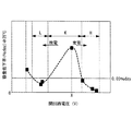
例えば、図2に一例が示されるように、開回路電圧と容量低下率(換言すると、電池劣化率)との関係を調べたところ、3.5V付近において電池劣化率が最も高くなることがわかった。従って、従来のように3.5Vを含む広い電圧範囲で蓄電装置を使用すると、電池の劣化を促進させることとなる。
本発明によれば、第1電池ユニットの動作停止中において、第1電池ユニットの充電状態が劣化範囲内となった場合に、この劣化範囲から外すべく、第1電池ユニットの充放電を実施するので、上述したような電池劣化率が高くなる充電範囲における保管を避けることができる。これにより、蓄電装置の劣化率を抑えることができる。
充電状態が劣化範囲内であるか否かの判定は、例えば、第1電池ユニットの電池電圧が予め設定されている劣化電圧範囲内であるか否か、または、第1電池ユニットの充電容量が予め設定されている劣化充電容量範囲内であるか否か、或いは、第1電池ユニットの充電率が予め設定されている劣化充電率範囲内であるか否かを判定することにより行われる。上記二次電池は、例えば、マンガン系正極材料を用いたリチウム二次電池である。
For example, as shown in FIG. 2, when the relationship between the open circuit voltage and the capacity reduction rate (in other words, the battery deterioration rate) is examined, it is found that the battery deterioration rate is the highest in the vicinity of 3.5V. It was. Therefore, when the power storage device is used in a wide voltage range including 3.5 V as in the conventional case, deterioration of the battery is promoted.
According to the present invention, when the charge state of the first battery unit falls within the deterioration range while the operation of the first battery unit is stopped, the first battery unit is charged / discharged so as to be removed from the deterioration range. Therefore, it is possible to avoid storage in the charging range where the battery deterioration rate is high as described above. Thereby, the deterioration rate of an electrical storage apparatus can be suppressed.
The determination as to whether or not the state of charge is within the deterioration range is made, for example, whether or not the battery voltage of the first battery unit is within a preset deterioration voltage range, or the charge capacity of the first battery unit is It is performed by determining whether or not the battery is within a preset deterioration charge capacity range or whether or not the charge rate of the first battery unit is within a preset deterioration charge rate range. The secondary battery is, for example, a lithium secondary battery using a manganese-based positive electrode material.
上記蓄電システムにおいて、前記計測手段は、前記第2電池ユニットの充電状態に関するパラメータ値を計測し、前記充放電制御手段は、前記第1電池ユニットの動作停止中において、前記第1電池ユニットの充電状態に関するパラメータ値及び前記第2電池ユニットの充電状態に関するパラメータ値に基づいて、前記第1電池ユニットと前記第2電池ユニットとの間で充放電を行うこととしてもよい。 In the power storage system, the measurement unit measures a parameter value related to a charging state of the second battery unit, and the charge / discharge control unit charges the first battery unit while the operation of the first battery unit is stopped. Charging / discharging may be performed between the first battery unit and the second battery unit based on a parameter value relating to a state and a parameter value relating to a charging state of the second battery unit.
第2電池ユニットの充電状態も考慮して第1電池ユニットと第2電池ユニットとの間で充放電を行うことにより、第1電池ユニットだけでなく第2電池ユニットについても適切な充電範囲で充放電を行わせることが可能となる。これにより、第2電池ユニットの寿命を長期化させることが可能となる。 By charging / discharging between the first battery unit and the second battery unit in consideration of the state of charge of the second battery unit, not only the first battery unit but also the second battery unit is charged within an appropriate charging range. It becomes possible to discharge. Thereby, it becomes possible to prolong the lifetime of a 2nd battery unit.
上記蓄電システムにおいて、前記充放電制御手段は、前記第1電池ユニットの劣化率が最大となる閾値を保有しており、前記計測手段によって計測されたパラメータ値が、前記劣化範囲内であり、且つ、前記閾値未満であった場合に、前記第1電池ユニットの電力を前記第2電池ユニットに供給し、前記計測手段によって計測されたパラメータ値が、前記劣化範囲内であり、且つ、前記閾値以上であった場合に、前記第2電池ユニットの電力を前記第1電池ユニットに供給することとしてもよい。 In the above power storage system, the charge / discharge control means has a threshold value at which the deterioration rate of the first battery unit is maximized, the parameter value measured by the measurement means is within the deterioration range, and When the power is less than the threshold, the power of the first battery unit is supplied to the second battery unit, and the parameter value measured by the measuring means is within the deterioration range and equal to or greater than the threshold. In this case, the power of the second battery unit may be supplied to the first battery unit.
このように、第1電池ユニットの劣化率が最大となる閾値を境に、充電を行うか、或いは、放電を行うかを決定することで、劣化率が最大となる点を避けながら、第1電池ユニットの充電状態を劣化範囲外とすることができる。これにより、第1電池ユニットの劣化を更に抑制することが可能となる。 In this way, by determining whether charging or discharging is performed at the threshold value at which the deterioration rate of the first battery unit is maximized, the first deterioration is avoided while avoiding the point where the deterioration rate is maximized. The state of charge of the battery unit can be outside the degradation range. Thereby, it becomes possible to further suppress deterioration of the first battery unit.
上記蓄電システムにおいて、前記充放電制御手段は、前記第1電池ユニットの動作停止中において、前記第1電池ユニットの前記パラメータ値が前記劣化範囲外であった場合に、前記第2電池ユニットの充電状態が、前記第1電池ユニットの運転停止時における前記第1電池ユニットの充電状態調整動作を行うのに適した所定の充電範囲となるように、前記第2電池ユニットの充放電を行うこととしてもよい。 In the power storage system, the charge / discharge control unit charges the second battery unit when the parameter value of the first battery unit is outside the deterioration range while the operation of the first battery unit is stopped. Charging and discharging the second battery unit so that the state becomes a predetermined charging range suitable for performing the charging state adjustment operation of the first battery unit when the first battery unit is stopped. Also good.
これにより、第2電池ユニットの充電状態を第1電池ユニットの充電状態を調整するのに最適な状態で確保することが可能となる。 Thereby, it becomes possible to ensure the state of charge of the second battery unit in an optimum state for adjusting the state of charge of the first battery unit.
上記蓄電システムにおいて、前記第1電池ユニットの電力を前記負荷に供給する放電動作中において、前記第2電池ユニットの充電状態が予め設定されている最適範囲外であった場合に、前記充放電制御手段は、前記第2電池ユニットの充電状態に応じて、前記第2電池ユニットの充電または放電を行うこととしてもよい。 In the power storage system, the charge / discharge control is performed when a charge state of the second battery unit is outside a preset optimum range during a discharge operation of supplying power of the first battery unit to the load. The means may charge or discharge the second battery unit according to the state of charge of the second battery unit.
このように、第1電池ユニットの放電動作中において、第2電池ユニットの充電状態に応じた充放電制御が充放電制御手段によって行われるので、第2電池ユニットの充電状態を最適範囲に保つことが可能となる。 In this way, during the discharge operation of the first battery unit, the charge / discharge control according to the charge state of the second battery unit is performed by the charge / discharge control means, so the charge state of the second battery unit is kept within the optimum range. Is possible.
上記蓄電システムにおいて、前記第1電池ユニットが前記電力変換手段を介して商用系統に接続され、前記商用系統からの電力を前記第1電池ユニットに充電する充電動作中において、前記第2電池ユニットの充電状態が予め設定されている最適範囲外であった場合に、前記充放電制御手段は、前記第2電池ユニットの充電状態に応じて、前記第2電池ユニットの充電または放電を行うこととしてもよい。 In the power storage system, the first battery unit is connected to a commercial system via the power conversion means, and during the charging operation of charging the first battery unit with power from the commercial system, the second battery unit When the state of charge is outside a preset optimum range, the charge / discharge control means may charge or discharge the second battery unit according to the state of charge of the second battery unit. Good.
このように、第1電池ユニットの充電動作中において、第2電池ユニットの充電状態に応じた充放電制御が充放電制御手段によって行われるので、第2電池ユニットの充電状態を最適範囲に保つことが可能となる。 In this way, during the charging operation of the first battery unit, the charge / discharge control according to the charge state of the second battery unit is performed by the charge / discharge control means, so the charge state of the second battery unit is kept within the optimum range. Is possible.
本発明の蓄電システムは、予め設定した時間帯(例えば、夜間の時間帯)に充電を行い、予め設定した時間帯(例えば、昼間の時間帯)に放電を行う電力貯蔵システムに用いられるのに好適である。電池容量が大きい電力貯蔵システムに本発明の蓄電システムを適用することにより、長寿命化を実現させることが可能となる。 The power storage system of the present invention is used in a power storage system that charges in a preset time zone (for example, a night time zone) and discharges in a preset time zone (for example, a daytime time zone). Is preferred. By applying the power storage system of the present invention to a power storage system having a large battery capacity, it is possible to realize a long life.
また、本発明は、上記いずれかの蓄電システムを備える電力貯蔵システムを提供する。 Moreover, this invention provides an electric power storage system provided with one of the said electrical storage systems.
本発明によれば、寿命を長期化することができるという効果を奏する。 According to the present invention, there is an effect that the lifetime can be extended.
以下に、本発明に係る蓄電システムの一実施形態について、図面を参照して説明する。
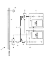
図1には、本発明の一実施形態に係る蓄電システムの概略構成が示されている。
図1に示されるように、本実施形態に係る蓄電システム1は、正極にマンガン系材料を使用した複数のリチウム二次電池を備える主電池ユニット(第1電池ユニット)2と、主電池ユニット2からの電力供給及び主電池ユニット2への電力供給が可能なバッファ電池ユニット(第2電池ユニット)3とを備えている。
Hereinafter, an embodiment of a power storage system according to the present invention will be described with reference to the drawings.
FIG. 1 shows a schematic configuration of a power storage system according to an embodiment of the present invention.
As shown in FIG. 1, a
主電池ユニット1は、電力変換装置4を介して商用系統Aに接続されている。また、商用系統Aには、負荷群5が接続されている。主電池ユニット2と電力変換装置4との間には、スイッチング素子6,7が直列に設けられており、主電池ユニット2と電力変換装置4との接続/非接続が制御可能とされている。また、主電池ユニット2とバッファ電池ユニット3との間には、主電池ユニット2とバッファ電池ユニット3間の充放電を制御するコンバータ(充放電制御手段)8が設けられている。主電池ユニット2とコンバータ8とは、スイッチング素子6、9を介して接続されるようになっている。
The
主電池ユニット2は、リチウム二次電池が直列に接続されて構成される組電池11と、該組電池11の充電状態等を監視する制御監視回路12を備えている。制御監視回路12は、例えば、組電池11の端子間電圧を検出する電圧センサ(計測手段)等の各種センサ及び主電池ユニット2を好適な状態に保つための種々の情報を保有し、この条件に基づいて主電池ユニット2の充放電制御を制御する制御部を備えている。
The
同様に、バッファ電池ユニット3は、二次電池が直列に接続されて構成される組電池15と、該組電池15の充電状態等を監視する制御監視回路16を備えている。制御監視回路16の構成については、上述した制御監視回路12と同様である。
制御監視回路12、16は、情報の相互伝達が可能な構成とされている。また、制御監視回路12は、電力変換装置4及びコンバータ8に対し、充放電に関する制御信号を送信することで、電力変換装置4及びコンバータ8の動作を制御する。
Similarly, the
The
以下、このような構成を備える蓄電システム1の動作について説明する。なお、以下の説明において、組電池の端子間電圧を「組電池電圧」、組電池を構成する各リチウム二次電池の端子間電圧を「単電池電圧」、各リチウム二次電池を「セル」と定義する。
Hereinafter, operation | movement of the
〔動作停止時(保管時を含む)〕
まず、蓄電システム1の動作停止時(保管時を含む)においては、スイッチング素子6,7,9が開状態とされ、主電池ユニット2は、電力変換装置4及びコンバータ8とは非接続状態とされる。
この状態において、主電池ユニット2の組電池11の組電池電圧(充電状態に関するパラメータ値)が制御監視回路12の備える電圧センサにより計測される。制御監視回路12の制御部は、電圧センサによって計測される組電池電圧が既定の劣化電圧範囲内であるか否かを判定する。
[When operation is stopped (including storage)]
First, when the operation of the
In this state, the assembled battery voltage (parameter value related to the charging state) of the assembled
ここで、劣化電圧範囲は、例えば、各セルの一日の劣化率が目標劣化率以下となる範囲に設定されている。例えば、組電池11を構成する各セルが図2に示すような劣化特性を有する場合であって、目標劣化率を0.03[%/day]とした場合、リチウム二次電池単体の劣化電圧範囲は、約2.4V以上約2.5未満の範囲及び約2.9V以上約3.8未満の範囲となる。従って、組電池全体に対応する劣化電圧範囲は、これらの劣化電圧範囲の電圧値にリチウム二次電池の個数を乗算した値となる。例えば、4個のリチウム二次電池により組電池11が構成されている場合には、9.6V以上10V未満及び11.6V以上15.2V未満が劣化電圧範囲として設定される。
Here, the deterioration voltage range is set, for example, in a range in which the daily deterioration rate of each cell is equal to or less than the target deterioration rate. For example, when each cell constituting the assembled
制御監視回路12は、組電池11の組電池電圧が上記の如く設定された劣化電圧範囲内であるか否かを判定し、劣化電圧範囲内であった場合には、スイッチング素子6,9をオン状態とすることで、主電池ユニット2とバッファ電池ユニット3とを接続状態とし、主電池ユニット2とバッファ電池ユニット3との間で電力の授受を行わせることにより、主電池ユニット2の組電池電圧が劣化電圧範囲から外れるようにする。
The
具体的には、制御監視回路12は、劣化電圧範囲内において組電池の劣化率が最大となる閾値Xを保有しており、組電池電圧が該閾値X未満であった場合に、図3に示すように、主電池ユニット2の電力をバッファ電池ユニット3に供給し、他方、組電池電圧が該閾値以上であった場合に、図4に示すように、主電池ユニット2に対してバッファ電池ユニット3の電力を供給する。
Specifically, the
例えば、図5に示した劣化特性を例に挙げると、劣化電圧範囲Kにおける閾値は、容量低下率が最大となるX(V)となる。従って、制御監視回路12は、組電池電圧が図5に係る劣化電圧範囲K内であって、かつ、閾値X以下の場合には、主電池ユニット2からバッファ電池ユニット3に放電することにより組電池電圧を低下させ、低劣化電圧範囲Lの状態まで変化させる。一方、組電池電圧が図5に係る劣化電圧範囲K内であって、かつ、閾値X以上の場合には、バッファ電池ユニット3から主電池ユニット2に電力供給することにより組電池電圧を上昇させ、低劣化電圧範囲Hの状態まで変化させる。
For example, taking the deterioration characteristic shown in FIG. 5 as an example, the threshold value in the deterioration voltage range K is X (V) at which the capacity reduction rate is maximized. Therefore, the
そして、組電池電圧を低劣化電圧範囲LまたはHまで変化させると、制御監視回路12は、コンバータ8の動作を停止させるとともに、スイッチング素子6,9を開状態とする。これにより、充放電制御が終了する。
When the assembled battery voltage is changed to the low deterioration voltage range L or H, the
そして、制御監視回路12が組電池電圧のモニタを所定の時間間隔で繰り返し行うことにより、適切な時期に主電池ユニット2の充放電が行われることとなる。これにより、主電池ユニット2の組電池を常に良好な状態に保ち、劣化を抑制することが可能となる。
The
また、蓄電システムの動作停止時(保管時を含む)において、主電池ユニット2の組電池11の組電池電圧が既定の劣化電圧範囲外であった場合には、バッファ電池ユニット3の組電池電圧が制御監視回路16の備える電圧センサ等により計測される。制御監視回路16の制御部は、電圧センサによって計測される組電池電圧が既定の最適電圧範囲内であるか否かを判定する。
Also, when the battery pack voltage of the
この最適電圧範囲は、主電池ユニット2の充電状態調整動作を行うのに適した所定の充電範囲である。具体的には、最適電圧範囲とは、主電池ユニット2の組電池電圧が劣化電圧範囲内であった場合に、主電池ユニット2の組電池電圧を劣化電圧範囲から外すべく行われる充放電制御が問題なく取り行われるような、バッファ電池ユニット3の電圧範囲をいう。このように、バッファ電池ユニット3の組電池電圧を最適電圧範囲としておくことで、上述した運転停止時における主電池ユニット2の充放電制御(充電状態調整動作)を滞りなく行うことが可能となる。
This optimum voltage range is a predetermined charging range suitable for performing the charging state adjustment operation of the
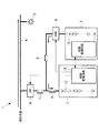
具体的には、制御監視回路16は、組電池電圧が最適電圧範囲の下限値未満であった場合には、その旨の信号を主電池ユニット2の制御監視回路12に出力する。制御監視回路12は、この信号を受信すると、図6に示すように、スイッチング素子6を開状態に維持したまま、スイッチング素子7,9を閉状態とし、商用系統の電力がバッファ電池ユニット3に供給されるように、電力変換装置4及びコンバータ8を制御する。この結果、バッファ電池ユニット3の組電池15が充電される。そして、組電池15の組電池電圧が最適電圧範囲内となったところで、その旨の信号が制御監視回路16から制御監視回路12に通知されると、スイッチング素子9,7が開状態とされ、電力変換装置4及びコンバータ8の動作が停止される。これにより、バッファ電池ユニット3の充電が停止される。
Specifically, when the assembled battery voltage is less than the lower limit value of the optimum voltage range, the
他方、制御監視回路16は、組電池電圧が最適電圧範囲の上限値以上であった場合には、その旨の信号を主電池ユニット2の制御監視回路12に出力する。制御監視回路12は、この信号を受信すると、図7に示すように、スイッチング素子6を開状態に維持したまま、スイッチング素子7,9を閉状態とし、バッファ電池ユニット3の電力が電力変換装置4を介して商用系統に供給されるように、コンバータ8を制御する。この結果、バッファ電池ユニット3の組電池15の放電が行われる。そして、組電池15の組電池電圧が最適電圧範囲内となったところで、その旨の信号が制御監視回路16から制御監視回路12に通知されると、スイッチング素子7,9が開状態とされ、電力変換装置4及びコンバータ8の動作が停止される。これにより、バッファ電池ユニット3の放電が停止される。
On the other hand, when the assembled battery voltage is equal to or higher than the upper limit value of the optimum voltage range, the
このように、バッファ電池ユニット3の組電池電圧が最適電圧範囲となるように、組電池15の充放電制御が行われるので、運転停止時において主電池ユニット2の組電池電圧が劣化電圧範囲内となった場合には、この劣化電圧範囲から外れさせる充放電制御を滞りなく行うことが可能となる。
In this way, charge / discharge control of the assembled
〔放電動作時〕
次に、蓄電システム1の放電動作中においては、スイッチング素子6,7が閉状態、スイッチング素子9が開状態とされ、主電池ユニット2と電力変換装置4とが接続される。電力変換装置4が作動することにより、主電池ユニット2に蓄電された電力が電力変換装置4を介して負荷群5に供給される。この放電動作が行われている期間において、バッファ電池ユニット3の組電池電圧が制御監視回路16の備える電圧センサ等により計測される。制御監視回路16の制御部は、電圧センサによって計測される組電池電圧が既定の最適電圧範囲内であるか否かを判定する。
[During discharge operation]
Next, during the discharging operation of the
制御監視回路16は、組電池電圧が最適電圧範囲の下限値未満であった場合には、その旨の信号を主電池ユニット2の制御監視回路12に出力する。制御監視回路12は、この信号を受信すると、図8に示すようにスイッチング素子9を閉状態とし、主電池ユニット2の電力がバッファ電池ユニット3にも供給されるように、コンバータ8を制御する。この結果、バッファ電池ユニット3の組電池15が充電される。そして、組電池15の組電池電圧が最適電圧範囲内となったところで、その旨の信号が制御監視回路16から制御監視回路12に通知されると、スイッチング素子9が開状態とされ、コンバータ8の動作が停止される。これにより、バッファ電池ユニット3の充電が停止される。
When the assembled battery voltage is less than the lower limit value of the optimum voltage range, the
他方、制御監視回路16は、組電池電圧が最適電圧範囲の上限値以上であった場合には、その旨の信号を主電池ユニット2の制御監視回路12に出力する。制御監視回路12は、この信号を受信すると、図9に示すようにスイッチング素子9を閉状態とし、バッファ電池ユニット3の電力が電力変換装置4にも供給されるように、コンバータ8を制御する。この結果、バッファ電池ユニット3の組電池15の放電が行われる。そして、組電池15の組電池電圧が最適電圧範囲内となったところで、その旨の信号が制御監視回路16から制御監視回路12に通知されると、スイッチング素子9が開状態とされ、コンバータ8の動作が停止される。これにより、バッファ電池ユニット3の放電が停止される。
On the other hand, when the assembled battery voltage is equal to or higher than the upper limit value of the optimum voltage range, the
〔充電動作時〕
次に、蓄電システム1の充電動作中においては、スイッチング素子6,7が閉状態、スイッチング素子9が開状態とされ、主電池ユニット2と電力変換装置4とが接続される。電力変換装置4が作動することにより、商用系統Aから主電池ユニット2に電力が供給され、組電池11の充電が行われる。
この充電動作が行われている期間において、バッファ電池ユニット3の組電池電圧が制御監視回路16の備える電圧センサ等に計測される。制御監視回路16の制御部は、電圧センサによって計測される組電池電圧が既定の最適電圧範囲内であるか否かを判定する。
(During charging operation)
Next, during the charging operation of the
During the period when this charging operation is performed, the assembled battery voltage of the
制御監視回路16は、組電池電圧が最適電圧範囲の下限値未満であった場合には、その旨の信号を主電池ユニット2の制御監視回路12に出力する。制御監視回路12は、この信号を受信すると、図10に示すようにスイッチング素子9を閉状態とし、商用系統Aからの電力がバッファ電池ユニット3にも供給されるように、コンバータ8を制御する。この結果、バッファ電池ユニット3の組電池15が充電される。そして、組電池15の組電池電圧が最適電圧範囲内となったところで、その旨の信号が制御監視回路16から制御監視回路12に通知されると、スイッチング素子9が開状態とされ、コンバータ8の動作が停止される。これにより、バッファ電池ユニット3の充電が停止される。
When the assembled battery voltage is less than the lower limit value of the optimum voltage range, the
他方、制御監視回路16は、組電池電圧が最適電圧範囲の上限値以上であった場合には、その旨の信号を主電池ユニット2の制御監視回路12に出力する。制御監視回路12は、この信号を受信すると、図11に示すようにスイッチング素子9を閉状態とし、バッファ電池ユニット3の電力が主電池ユニット2に供給されるように、コンバータ8を制御する。この結果、バッファ電池ユニット3の組電池15の放電が行われる。そして、組電池15の組電池電圧が最適電圧範囲内となったところで、その旨の信号が制御監視回路16から制御監視回路12に通知されると、スイッチング素子9が開状態とされ、コンバータ8の動作が停止される。これにより、バッファ電池ユニット3の放電が停止される。
On the other hand, when the assembled battery voltage is equal to or higher than the upper limit value of the optimum voltage range, the
以上説明してきたように、本実施形態に係る蓄電システム1によれば、主電池ユニット2の組電池電圧が常に劣化電圧範囲外となるように、バッファ電池ユニット3との間の電力のやり取りが制御されるので、主電池ユニット2の組電池11を電池劣化の低い電圧範囲に制限して保管することができる。これにより、電池の劣化を抑制することができ、電池寿命を長期化させることができる。
また、主電池ユニット2の充放電動作中においては、バッファ電池ユニット3の組電池電圧が最適電圧範囲となるように、組電池15の充放電制御が行われるので、運転停止時における主電池ユニット2の充放電制御を滞りなく行うことが可能となる。
As described above, according to the
Further, during the charging / discharging operation of the
なお、上述した実施形態では、組電池電圧を組電池11、15の充電状態を把握するためのパラメータ値として用いたが、これに代えて、組電池11、15の充電容量、充電率SOC等を用いることとしてもよい。更に、組電池電圧に代えて、各セルの端子間電圧(単電池電圧)を用いることとしてもよい。この場合、単電池電圧に対応する劣化電圧範囲や最適電圧範囲を設定しておけばよい。また、各セルの電圧をパラメータとする外、上述のように、充電容量、充電率SOCを用いて判定することとしてもよい。
In the above-described embodiment, the assembled battery voltage is used as a parameter value for grasping the charging state of the assembled
上述した本実施形態に係る蓄電システムは、例えば、電力料金が安価な夜間の時間帯(例えば、23時から翌日の6時)に商用系統Aから電力を主電池ユニット2の組電池11に充電し、電力料金が比較的高い昼間の時間帯(例えば、6時から23時)に主電池ユニット2の組電池11に蓄えた電力を負荷群5へ供給するような電力貯蔵システムに利用されるのに適している。
The power storage system according to the present embodiment described above charges, for example, power from the commercial system A to the assembled
また、上述した実施形態に係る蓄電システムでは、主電池ユニット2の組電池電圧が常に劣化電圧範囲外となるように、バッファ電池ユニット3との間で充放電制御を行っていたが、バッファ電池ユニット3の組電池電圧についてもモニタし、この組電池電圧が予め設定されている電圧範囲内となるように、主電池ユニット2とバッファ電池ユニット3との間の充放電制御を行うこととしてもよい。
このように、バッファ電池ユニット3の充電状態についても考慮することにより、バッファ電池ユニット3の寿命を長期化することが可能となる。
In the power storage system according to the above-described embodiment, the charge / discharge control is performed with the
Thus, by considering the state of charge of the
以上、本発明の実施形態について図面を参照して詳述してきたが、具体的な構成はこの実施形態に限られるものではなく、本発明の要旨を逸脱しない範囲の設計変更等も含まれる。 As mentioned above, although embodiment of this invention was explained in full detail with reference to drawings, the specific structure is not restricted to this embodiment, The design change etc. of the range which does not deviate from the summary of this invention are included.
1 蓄電システム
2 主電池ユニット
3 バッファ電池ユニット
4 電力変換装置
5 負荷群
6,7,9 スイッチング素子
8 コンバータ
11,15 組電池
12,16 制御監視回路
DESCRIPTION OF
Claims (8)
前記第1電池ユニットからの電力供給及び前記第1電池ユニットへの電力供給が可能な第2電池ユニットと、
負荷と前記第1電池ユニットとの間に設けられ、前記第1電池ユニットから前記負荷に供給する電力を制御する電力変換手段と、
前記第1電池ユニットと前記第2電池ユニットとの間に設けられ、前記第1電池ユニットと前記第2電池ユニット間の充放電を制御する充放電制御手段と、
前記第1電池ユニットの充電状態に関するパラメータ値を計測する計測手段と
を備え、
前記充放電制御手段は、前記第1電池ユニットの動作停止中において、前記第1電池ユニットの充電状態に関するパラメータ値が予め設定されている劣化範囲内である場合に、前記第1電池ユニットと前記第2電池ユニットとの間で充放電を行う蓄電システム。 A first battery unit having at least one secondary battery;
A second battery unit capable of supplying power from the first battery unit and supplying power to the first battery unit;
A power conversion unit that is provided between a load and the first battery unit and controls power supplied from the first battery unit to the load;
Charge / discharge control means for controlling charge / discharge between the first battery unit and the second battery unit, provided between the first battery unit and the second battery unit;
Measuring means for measuring a parameter value relating to a charging state of the first battery unit,
The charge / discharge control means, when the parameter value relating to the state of charge of the first battery unit is within a preset deterioration range while the operation of the first battery unit is stopped, A power storage system that charges and discharges with the second battery unit.
前記充放電制御手段は、前記第1電池ユニットの動作停止中において、前記第1電池ユニットの充電状態に関するパラメータ値及び前記第2電池ユニットの充電状態に関するパラメータ値に基づいて、前記第1電池ユニットと前記第2電池ユニットとの間で充放電を行う請求項1に記載の蓄電システム。 The measuring means measures a parameter value related to a charging state of the second battery unit;
The charge / discharge control means is configured to determine the first battery unit based on a parameter value related to a charge state of the first battery unit and a parameter value related to a charge state of the second battery unit while the operation of the first battery unit is stopped. The power storage system according to claim 1, wherein charging / discharging is performed between the first battery unit and the second battery unit.
前記第1電池ユニットの劣化率が最大となる閾値を保有しており、
前記計測手段によって計測された前記第1電池ユニットの充電状態に関するパラメータ値が、前記劣化範囲内であり、且つ、前記閾値未満であった場合に、前記第1電池ユニットの電力を前記第2電池ユニットに供給し、
前記計測手段によって計測された前記第1電池ユニットの充電状態に関するパラメータ値が、前記劣化範囲内であり、且つ、前記閾値以上であった場合に、前記第2電池ユニットの電力を前記第1電池ユニットに供給する請求項1または請求項2に記載の蓄電システム。 The charge / discharge control means includes
Possesses a threshold that maximizes the degradation rate of the first battery unit;
When the parameter value relating to the state of charge of the first battery unit measured by the measuring means is within the deterioration range and less than the threshold, the power of the first battery unit is converted to the second battery. Supply to the unit,
When the parameter value relating to the state of charge of the first battery unit measured by the measuring means is within the deterioration range and equal to or greater than the threshold value, the power of the second battery unit is converted to the first battery. The electrical storage system of Claim 1 or Claim 2 supplied to a unit.
前記第1電池ユニットの動作停止中において、前記第1電池ユニットの前記パラメータ値が前記劣化範囲外であった場合に、前記第2電池ユニットの充電状態が、前記第1電池ユニットの運転停止時における前記第1電池ユニットの充電状態調整動作を行うのに適した所定の充電範囲となるように、前記第2電池ユニットの充放電を行う請求項1から請求項3のいずれかに記載の蓄電システム。 The charge / discharge control means includes
When the parameter value of the first battery unit is outside the deterioration range while the operation of the first battery unit is stopped, the state of charge of the second battery unit is the time when the operation of the first battery unit is stopped. The power storage according to any one of claims 1 to 3, wherein the second battery unit is charged and discharged so that a predetermined charging range suitable for performing a state of charge adjustment operation of the first battery unit is performed. system.
Priority Applications (1)
| Application Number | Priority Date | Filing Date | Title |
|---|---|---|---|
| JP2008266310A JP5478870B2 (en) | 2008-10-15 | 2008-10-15 | Power storage system and power storage system |
Applications Claiming Priority (1)
| Application Number | Priority Date | Filing Date | Title |
|---|---|---|---|
| JP2008266310A JP5478870B2 (en) | 2008-10-15 | 2008-10-15 | Power storage system and power storage system |
Publications (3)
| Publication Number | Publication Date |
|---|---|
| JP2010097760A true JP2010097760A (en) | 2010-04-30 |
| JP2010097760A5 JP2010097760A5 (en) | 2011-05-26 |
| JP5478870B2 JP5478870B2 (en) | 2014-04-23 |
Family
ID=42259303
Family Applications (1)
| Application Number | Title | Priority Date | Filing Date |
|---|---|---|---|
| JP2008266310A Expired - Fee Related JP5478870B2 (en) | 2008-10-15 | 2008-10-15 | Power storage system and power storage system |
Country Status (1)
| Country | Link |
|---|---|
| JP (1) | JP5478870B2 (en) |
Cited By (17)
| Publication number | Priority date | Publication date | Assignee | Title |
|---|---|---|---|---|
| JP2010183697A (en) * | 2009-02-04 | 2010-08-19 | Mitsubishi Heavy Ind Ltd | Power supply system and power supply method thereof |
| WO2011118294A1 (en) * | 2010-03-23 | 2011-09-29 | 日本電気株式会社 | Method for charging/discharging lithium-ion secondary battery, and charging/discharging system |
| JP2012138981A (en) * | 2010-12-24 | 2012-07-19 | Nec Energy Devices Ltd | Discharge controller, discharge control method, and program |
| WO2013038764A1 (en) * | 2011-09-15 | 2013-03-21 | 日本電気株式会社 | Secondary battery system, and method for operating secondary battery |
| WO2013038763A1 (en) * | 2011-09-15 | 2013-03-21 | 日本電気株式会社 | Secondary battery system and method for charging/discharging same |
| WO2013094344A1 (en) * | 2011-12-22 | 2013-06-27 | 日本電気株式会社 | Storage battery device and charging control method |
| US20130249491A1 (en) * | 2010-12-24 | 2013-09-26 | Nec Corporation | Discharge controller |
| JP2014131369A (en) * | 2012-12-28 | 2014-07-10 | Kawasaki Heavy Ind Ltd | Power control system |
| JP2015122907A (en) * | 2013-12-24 | 2015-07-02 | 三菱自動車工業株式会社 | Secondary battery management device |
| JP2015171197A (en) * | 2014-03-05 | 2015-09-28 | 三菱自動車工業株式会社 | Management device of secondary battery |
| EP3026752A1 (en) * | 2014-11-27 | 2016-06-01 | Samsung SDI Co., Ltd. | Battery pack and method for controlling the same |
| EP3148037A1 (en) * | 2015-09-24 | 2017-03-29 | Samsung SDI Co., Ltd. | Energy storage system |
| EP3148042A1 (en) * | 2015-09-24 | 2017-03-29 | Samsung SDI Co., Ltd. | Uninterruptible power supply |
| JP2017189045A (en) * | 2016-04-07 | 2017-10-12 | 株式会社日立製作所 | Storage battery system and storage battery control method |
| JP6651063B1 (en) * | 2019-06-12 | 2020-02-19 | 三菱電機株式会社 | Charge / discharge control device and charge / discharge control method |
| DE102018218538A1 (en) * | 2018-10-30 | 2020-04-30 | Robert Bosch Gmbh | Method for matching the charge states of a plurality of electrochemical energy stores which can be connected in parallel |
| DE102018218577A1 (en) * | 2018-10-30 | 2020-04-30 | Robert Bosch Gmbh | Method for adapting charging states of a plurality of electrochemical energy stores which can be connected in parallel |
Citations (8)
| Publication number | Priority date | Publication date | Assignee | Title |
|---|---|---|---|---|
| JP2003244854A (en) * | 2002-02-13 | 2003-08-29 | Mitsubishi Heavy Ind Ltd | Charge and discharge controller for storage apparatus, charge and discharge control method, and power storage system |
| JP2006223035A (en) * | 2005-02-09 | 2006-08-24 | Hitachi Advanced Digital Inc | Battery control system |
| JP2006304393A (en) * | 2005-04-15 | 2006-11-02 | Toyota Motor Corp | Power supply, its control method and vehicle |
| JP2006333662A (en) * | 2005-05-27 | 2006-12-07 | Toyota Industries Corp | Device and method for judging deterioration degree of battery |
| JP2007225430A (en) * | 2006-02-23 | 2007-09-06 | Furukawa Electric Co Ltd:The | Degradation diagnostic apparatus and method for storage battery, and storage battery system |
| JP2008054473A (en) * | 2006-08-28 | 2008-03-06 | Sharp Corp | Power conditioner having electric storage function |
| JP2008125163A (en) * | 2006-11-08 | 2008-05-29 | Toyota Motor Corp | Electric vehicle |
| JP2008148389A (en) * | 2006-12-06 | 2008-06-26 | Auto Network Gijutsu Kenkyusho:Kk | Power supply |
-
2008
- 2008-10-15 JP JP2008266310A patent/JP5478870B2/en not_active Expired - Fee Related
Patent Citations (8)
| Publication number | Priority date | Publication date | Assignee | Title |
|---|---|---|---|---|
| JP2003244854A (en) * | 2002-02-13 | 2003-08-29 | Mitsubishi Heavy Ind Ltd | Charge and discharge controller for storage apparatus, charge and discharge control method, and power storage system |
| JP2006223035A (en) * | 2005-02-09 | 2006-08-24 | Hitachi Advanced Digital Inc | Battery control system |
| JP2006304393A (en) * | 2005-04-15 | 2006-11-02 | Toyota Motor Corp | Power supply, its control method and vehicle |
| JP2006333662A (en) * | 2005-05-27 | 2006-12-07 | Toyota Industries Corp | Device and method for judging deterioration degree of battery |
| JP2007225430A (en) * | 2006-02-23 | 2007-09-06 | Furukawa Electric Co Ltd:The | Degradation diagnostic apparatus and method for storage battery, and storage battery system |
| JP2008054473A (en) * | 2006-08-28 | 2008-03-06 | Sharp Corp | Power conditioner having electric storage function |
| JP2008125163A (en) * | 2006-11-08 | 2008-05-29 | Toyota Motor Corp | Electric vehicle |
| JP2008148389A (en) * | 2006-12-06 | 2008-06-26 | Auto Network Gijutsu Kenkyusho:Kk | Power supply |
Cited By (37)
| Publication number | Priority date | Publication date | Assignee | Title |
|---|---|---|---|---|
| JP2010183697A (en) * | 2009-02-04 | 2010-08-19 | Mitsubishi Heavy Ind Ltd | Power supply system and power supply method thereof |
| WO2011118294A1 (en) * | 2010-03-23 | 2011-09-29 | 日本電気株式会社 | Method for charging/discharging lithium-ion secondary battery, and charging/discharging system |
| JP2012143151A (en) * | 2010-03-23 | 2012-07-26 | Nec Corp | Method for charging/discharging lithium-ion secondary battery, and charging/discharging system |
| US20130249491A1 (en) * | 2010-12-24 | 2013-09-26 | Nec Corporation | Discharge controller |
| JP2012138981A (en) * | 2010-12-24 | 2012-07-19 | Nec Energy Devices Ltd | Discharge controller, discharge control method, and program |
| US9444268B2 (en) * | 2010-12-24 | 2016-09-13 | Nec Energy Devices, Ltd. | Discharge controller |
| US20130265008A1 (en) * | 2010-12-24 | 2013-10-10 | Nec Corporation | Discharge controller |
| CN103262381A (en) * | 2010-12-24 | 2013-08-21 | Nec能源元器件株式会社 | Discharge controller |
| EP2757652A4 (en) * | 2011-09-15 | 2015-05-13 | Nec Corp | Secondary battery system, and method for operating secondary battery |
| US9531212B2 (en) | 2011-09-15 | 2016-12-27 | Nec Corporation | Secondary battery system and charge and discharge method for the same |
| US9450439B2 (en) | 2011-09-15 | 2016-09-20 | Nec Corporation | Secondary battery system and operating method of secondary battery |
| JP5569643B2 (en) * | 2011-09-15 | 2014-08-13 | 日本電気株式会社 | Secondary battery system and charging / discharging method thereof |
| JPWO2013038763A1 (en) * | 2011-09-15 | 2015-03-23 | 日本電気株式会社 | Secondary battery system and charging / discharging method thereof |
| JPWO2013038764A1 (en) * | 2011-09-15 | 2015-03-23 | 日本電気株式会社 | Secondary battery system and secondary battery operation method |
| WO2013038764A1 (en) * | 2011-09-15 | 2013-03-21 | 日本電気株式会社 | Secondary battery system, and method for operating secondary battery |
| WO2013038763A1 (en) * | 2011-09-15 | 2013-03-21 | 日本電気株式会社 | Secondary battery system and method for charging/discharging same |
| WO2013094344A1 (en) * | 2011-12-22 | 2013-06-27 | 日本電気株式会社 | Storage battery device and charging control method |
| JPWO2013094344A1 (en) * | 2011-12-22 | 2015-04-27 | 日本電気株式会社 | Storage battery device and charge control method |
| US9472976B2 (en) | 2011-12-22 | 2016-10-18 | Nec Corporation | Storage battery device and charging control method |
| JP2014131369A (en) * | 2012-12-28 | 2014-07-10 | Kawasaki Heavy Ind Ltd | Power control system |
| JP2015122907A (en) * | 2013-12-24 | 2015-07-02 | 三菱自動車工業株式会社 | Secondary battery management device |
| JP2015171197A (en) * | 2014-03-05 | 2015-09-28 | 三菱自動車工業株式会社 | Management device of secondary battery |
| EP3026752A1 (en) * | 2014-11-27 | 2016-06-01 | Samsung SDI Co., Ltd. | Battery pack and method for controlling the same |
| US10284009B2 (en) | 2015-09-24 | 2019-05-07 | Samsung Sdi Co., Ltd. | Uninterruptible power supply |
| EP3148037A1 (en) * | 2015-09-24 | 2017-03-29 | Samsung SDI Co., Ltd. | Energy storage system |
| US20170093187A1 (en) * | 2015-09-24 | 2017-03-30 | Samsung Sdi Co., Ltd. | Energy storage system |
| CN106816884A (en) * | 2015-09-24 | 2017-06-09 | 三星Sdi株式会社 | Energy storage system |
| CN106877482A (en) * | 2015-09-24 | 2017-06-20 | 三星Sdi株式会社 | Uninterrupted power source |
| CN106877482B (en) * | 2015-09-24 | 2021-06-08 | 三星Sdi株式会社 | Uninterruptible power supply |
| EP3148042A1 (en) * | 2015-09-24 | 2017-03-29 | Samsung SDI Co., Ltd. | Uninterruptible power supply |
| JP2017189045A (en) * | 2016-04-07 | 2017-10-12 | 株式会社日立製作所 | Storage battery system and storage battery control method |
| CN111114387A (en) * | 2018-10-30 | 2020-05-08 | 罗伯特·博世有限公司 | Method for equalizing the state of charge of a plurality of electrochemical energy stores that can be connected in parallel |
| DE102018218577A1 (en) * | 2018-10-30 | 2020-04-30 | Robert Bosch Gmbh | Method for adapting charging states of a plurality of electrochemical energy stores which can be connected in parallel |
| DE102018218538A1 (en) * | 2018-10-30 | 2020-04-30 | Robert Bosch Gmbh | Method for matching the charge states of a plurality of electrochemical energy stores which can be connected in parallel |
| CN111114387B (en) * | 2018-10-30 | 2024-04-09 | 罗伯特·博世有限公司 | Method for equalizing the charge states of a plurality of electrochemical energy stores that can be connected in parallel |
| JP6651063B1 (en) * | 2019-06-12 | 2020-02-19 | 三菱電機株式会社 | Charge / discharge control device and charge / discharge control method |
| WO2020250342A1 (en) * | 2019-06-12 | 2020-12-17 | 三菱電機株式会社 | Charging/discharging control device, and method for controlling charging and discharging |
Also Published As
| Publication number | Publication date |
|---|---|
| JP5478870B2 (en) | 2014-04-23 |
Similar Documents
| Publication | Publication Date | Title |
|---|---|---|
| JP5478870B2 (en) | Power storage system and power storage system | |
| US9444267B2 (en) | Cell voltage equalizer for multi-cell battery pack which determines the waiting time between equalization operations based on the voltage difference and the state of charge level | |
| JP5319903B2 (en) | Power storage system | |
| CN105518924B (en) | Battery apparatus and electric vehicle | |
| JP5764260B2 (en) | Battery system and method for supplying an intermediate voltage | |
| EP3026752A1 (en) | Battery pack and method for controlling the same | |
| WO2017130614A1 (en) | Battery control device | |
| JP6897765B2 (en) | Management device, power storage device and power storage system | |
| US20110181245A1 (en) | Unitized charging and discharging battery management system and programmable battery management module thereof | |
| US7633268B2 (en) | Charging apparatus | |
| JP2014511095A (en) | Rechargeable battery system and method of operating the same | |
| JP2014504140A (en) | Rechargeable battery system and method of operating the same | |
| US20100237832A1 (en) | Charging method and charging system | |
| JP6145712B2 (en) | Secondary battery charging system and method, and battery pack | |
| US20150035492A1 (en) | Adjusting device, battery pack, and adjusting method | |
| US20140159664A1 (en) | Method of manufacturing battery pack and battery pack | |
| JP2014507924A (en) | Rechargeable battery system and method of operating the same | |
| WO2017212815A1 (en) | Trickle charging power supply system | |
| KR102531486B1 (en) | Active battery management system | |
| KR102002343B1 (en) | Apparatus and method for charging and discharging battery for uninterruptible power supply | |
| JP3796918B2 (en) | Battery device | |
| JP2011055592A (en) | Secondary cell and method for charging and discharging the same | |
| US9634499B2 (en) | Adjusting device, battery pack device, and adjusting method | |
| JP5371462B2 (en) | Power supply system and power supply method thereof | |
| JP2008005616A (en) | Backup power-supply unit |
Legal Events
| Date | Code | Title | Description |
|---|---|---|---|
| A521 | Written amendment |
Free format text: JAPANESE INTERMEDIATE CODE: A523 Effective date: 20110413 |
|
| A621 | Written request for application examination |
Free format text: JAPANESE INTERMEDIATE CODE: A621 Effective date: 20110413 |
|
| A977 | Report on retrieval |
Free format text: JAPANESE INTERMEDIATE CODE: A971007 Effective date: 20130321 |
|
| A131 | Notification of reasons for refusal |
Free format text: JAPANESE INTERMEDIATE CODE: A131 Effective date: 20130402 |
|
| TRDD | Decision of grant or rejection written | ||
| A01 | Written decision to grant a patent or to grant a registration (utility model) |
Free format text: JAPANESE INTERMEDIATE CODE: A01 Effective date: 20140114 |
|
| A61 | First payment of annual fees (during grant procedure) |
Free format text: JAPANESE INTERMEDIATE CODE: A61 Effective date: 20140212 |
|
| R150 | Certificate of patent or registration of utility model |
Ref document number: 5478870 Country of ref document: JP Free format text: JAPANESE INTERMEDIATE CODE: R150 |
|
| S111 | Request for change of ownership or part of ownership |
Free format text: JAPANESE INTERMEDIATE CODE: R313117 |
|
| R350 | Written notification of registration of transfer |
Free format text: JAPANESE INTERMEDIATE CODE: R350 |
|
| R250 | Receipt of annual fees |
Free format text: JAPANESE INTERMEDIATE CODE: R250 |
|
| LAPS | Cancellation because of no payment of annual fees |