JP2017189045A - Storage battery system and storage battery control method - Google Patents
Storage battery system and storage battery control method Download PDFInfo
- Publication number
- JP2017189045A JP2017189045A JP2016077011A JP2016077011A JP2017189045A JP 2017189045 A JP2017189045 A JP 2017189045A JP 2016077011 A JP2016077011 A JP 2016077011A JP 2016077011 A JP2016077011 A JP 2016077011A JP 2017189045 A JP2017189045 A JP 2017189045A
- Authority
- JP
- Japan
- Prior art keywords
- storage battery
- threshold value
- storage
- charge
- control device
- Prior art date
- Legal status (The legal status is an assumption and is not a legal conclusion. Google has not performed a legal analysis and makes no representation as to the accuracy of the status listed.)
- Pending
Links
Images


Classifications
-
- Y—GENERAL TAGGING OF NEW TECHNOLOGICAL DEVELOPMENTS; GENERAL TAGGING OF CROSS-SECTIONAL TECHNOLOGIES SPANNING OVER SEVERAL SECTIONS OF THE IPC; TECHNICAL SUBJECTS COVERED BY FORMER USPC CROSS-REFERENCE ART COLLECTIONS [XRACs] AND DIGESTS
- Y02—TECHNOLOGIES OR APPLICATIONS FOR MITIGATION OR ADAPTATION AGAINST CLIMATE CHANGE
- Y02E—REDUCTION OF GREENHOUSE GAS [GHG] EMISSIONS, RELATED TO ENERGY GENERATION, TRANSMISSION OR DISTRIBUTION
- Y02E60/00—Enabling technologies; Technologies with a potential or indirect contribution to GHG emissions mitigation
- Y02E60/10—Energy storage using batteries
-
- Y—GENERAL TAGGING OF NEW TECHNOLOGICAL DEVELOPMENTS; GENERAL TAGGING OF CROSS-SECTIONAL TECHNOLOGIES SPANNING OVER SEVERAL SECTIONS OF THE IPC; TECHNICAL SUBJECTS COVERED BY FORMER USPC CROSS-REFERENCE ART COLLECTIONS [XRACs] AND DIGESTS
- Y02—TECHNOLOGIES OR APPLICATIONS FOR MITIGATION OR ADAPTATION AGAINST CLIMATE CHANGE
- Y02E—REDUCTION OF GREENHOUSE GAS [GHG] EMISSIONS, RELATED TO ENERGY GENERATION, TRANSMISSION OR DISTRIBUTION
- Y02E70/00—Other energy conversion or management systems reducing GHG emissions
- Y02E70/30—Systems combining energy storage with energy generation of non-fossil origin
-
- Y—GENERAL TAGGING OF NEW TECHNOLOGICAL DEVELOPMENTS; GENERAL TAGGING OF CROSS-SECTIONAL TECHNOLOGIES SPANNING OVER SEVERAL SECTIONS OF THE IPC; TECHNICAL SUBJECTS COVERED BY FORMER USPC CROSS-REFERENCE ART COLLECTIONS [XRACs] AND DIGESTS
- Y04—INFORMATION OR COMMUNICATION TECHNOLOGIES HAVING AN IMPACT ON OTHER TECHNOLOGY AREAS
- Y04S—SYSTEMS INTEGRATING TECHNOLOGIES RELATED TO POWER NETWORK OPERATION, COMMUNICATION OR INFORMATION TECHNOLOGIES FOR IMPROVING THE ELECTRICAL POWER GENERATION, TRANSMISSION, DISTRIBUTION, MANAGEMENT OR USAGE, i.e. SMART GRIDS
- Y04S10/00—Systems supporting electrical power generation, transmission or distribution
- Y04S10/14—Energy storage units
Landscapes
- Charge And Discharge Circuits For Batteries Or The Like (AREA)
- Secondary Cells (AREA)
- Remote Monitoring And Control Of Power-Distribution Networks (AREA)
- Supply And Distribution Of Alternating Current (AREA)
Abstract
Description
本発明は、蓄電池システム及び蓄電池制御方法に関する。 The present invention relates to a storage battery system and a storage battery control method.
現在、電力会社から供給される電力の大部分は火力発電、水力発電、原子力発電によって生成されたものである。しかし近年、環境負荷軽減の観点から、再生可能エネルギー(太陽光発電、風力発電等)を利用する発電システムの導入が増加している。 Currently, most of the power supplied by electric power companies is generated by thermal power generation, hydroelectric power generation, and nuclear power generation. However, in recent years, the introduction of power generation systems that use renewable energy (solar power generation, wind power generation, etc.) is increasing from the viewpoint of reducing environmental impact.
太陽光や風力などの自然エネルギーを用いて発電するシステムは、環境変化の影響を受けやすいため出力変動が激しく、電力系統を不安定にさせる要因となっている。そのため、再生可能エネルギーによる発電システムには、複数の蓄電池が複数直並列に接続されている大容量の蓄電池システムを併設し、電力系統の安定化を図ることが行われている。 Systems that generate electricity using natural energy such as sunlight and wind power are susceptible to environmental changes, and output fluctuations are severe, causing the power system to become unstable. For this reason, a power generation system using renewable energy is provided with a large-capacity storage battery system in which a plurality of storage batteries are connected in series and parallel to stabilize the power system.
蓄電池を用いて電力系統を安定化させる為には、電力系統の需要と供給のバランスを取る必要があり、必要に応じて併設された蓄電池に充放電させている。しかし、充電と放電の割合が1対1となる事は極めて少なく、通常はどちらか一方に偏る傾向がある。具体的には、蓄電池の充電率(SOC:State Of Charge)は、蓄電池の充放電可能な容量から決まる上限値又は下限値に到達しやすく、上限値又は下限値に到達した場合、蓄電池が過充電又は過放電にならないよう出力を制限又は停止することになる。なお、以下の説明では、実際の運用時に設定される上限値及び下限値を、SOC上限値及びSOC下限値と称する。 In order to stabilize an electric power system using a storage battery, it is necessary to balance the demand and supply of the electric power system, and the storage battery provided side by side is charged and discharged as necessary. However, the ratio of charging and discharging is extremely rare, and usually tends to be biased to either one. Specifically, the state of charge (SOC) of the storage battery easily reaches an upper limit value or a lower limit value determined from the chargeable / dischargeable capacity of the storage battery. The output is limited or stopped so as not to be charged or overdischarged. In the following description, the upper limit value and the lower limit value set during actual operation are referred to as the SOC upper limit value and the SOC lower limit value.
蓄電池は、充電池時にはSOC上限値まで充電され、放電時にはSOC下限値まで放電される。例えばある蓄電池システムでは、蓄電池の満充電容量を100%としたとき、SOC上限値を85%、SOC下限値を15%として、その85%と15%との間で充放電を行う運用が行われる。これは、100%までの満充電や0%までの完全な放電で蓄電池が劣化することを防ぐためである。
しかしながら、上述したSOC上限値やSOC下限値は、蓄電池の特性上劣化が完全に防げる値ではなく、蓄電池を使う上での経済性と電池寿命とのバランスを取った値に設定される。すなわち、SOC上限値とSOC下限値との間で決まる蓄電池の実充電容量が少なすぎると、蓄電池システムが充電できる容量が非常に少なくなってしまうため、ある程度の劣化があることを前提として、上述した85%や15%の値を設定している。したがって、実際の運用上では、蓄電池の充電率がSOC上限値やSOC下限値の状態で継続することは好ましくない。
The storage battery is charged to the SOC upper limit value when the battery is charged, and discharged to the SOC lower limit value when discharging. For example, in a certain storage battery system, assuming that the full charge capacity of the storage battery is 100%, the SOC upper limit value is 85%, the SOC lower limit value is 15%, and charging / discharging is performed between 85% and 15%. Is called. This is to prevent the storage battery from being deteriorated by full charge up to 100% or complete discharge up to 0%.
However, the above-described SOC upper limit value and SOC lower limit value are not values that can completely prevent deterioration due to the characteristics of the storage battery, but are set to values that balance economics and battery life in using the storage battery. That is, if the actual charge capacity of the storage battery determined between the SOC upper limit value and the SOC lower limit value is too small, the capacity that can be charged by the storage battery system will be very small. The values of 85% and 15% are set. Therefore, in actual operation, it is not preferable that the charging rate of the storage battery continues in a state where the SOC upper limit value or the SOC lower limit value is reached.
特許文献1には、蓄電池システムにおいて、特性の異なる複数の蓄電池を備えて、その特性の異なる複数の蓄電池への分配状況を変化させる技術が開示されている。特許文献1に記載の技術によれば、特性の異なる複数の蓄電池を用意して、それぞれの蓄電池の特性に合わせた制御を行うことで、蓄電システム全体としてのパフォーマンスの向上を図ることができるとされている。 Patent Document 1 discloses a technique in which a storage battery system includes a plurality of storage batteries having different characteristics and changes the distribution status to the plurality of storage batteries having different characteristics. According to the technology described in Patent Document 1, by preparing a plurality of storage batteries having different characteristics and performing control according to the characteristics of each storage battery, it is possible to improve the performance of the entire storage system. Has been.
ところが、特許文献1に記載されるように特性の異なる複数の蓄電池でシステムを構築した場合には、既存の蓄電池システムにそのまま適用することができないという問題がある。通常、複数の蓄電池で構成される大容量の蓄電池システムは、同じ特性の蓄電池を多数使用したシステムが一般的である。したがって、既存の蓄電池システムに、制御用ソフトウェアの変更で、特許文献1に記載された蓄電池制御技術を適用することは困難であり、蓄電池の入れ替えなどの大規模な改修が必要になってしまう。 However, as described in Patent Document 1, when a system is constructed with a plurality of storage batteries having different characteristics, there is a problem that it cannot be applied to an existing storage battery system as it is. In general, a large-capacity storage battery system including a plurality of storage batteries is generally a system using a large number of storage batteries having the same characteristics. Therefore, it is difficult to apply the storage battery control technique described in Patent Document 1 to the existing storage battery system by changing the control software, and a large-scale modification such as replacement of the storage battery becomes necessary.
本発明の目的は、複数の蓄電池の特性についての制約をなくした上で、蓄電システム全体としてのパフォーマンスの向上及び蓄電池の寿命の長寿命化を図ることができる蓄電池システム及び蓄電池制御方法を提供することにある。 An object of the present invention is to provide a storage battery system and a storage battery control method capable of improving the performance of the entire power storage system and extending the life of the storage battery while eliminating restrictions on characteristics of a plurality of storage batteries. There is.
上記課題を解決するために、例えば特許請求の範囲に記載の構成を採用する。
本願は上記課題を解決する手段を複数含んでいるが、その一例を挙げるならは、個別にインバーターが接続されて個別に充電及び放電が可能な複数の蓄電池と、複数の蓄電池の充電量を監視して、複数の蓄電池に対して個別に充電指令又は放電指令を与える蓄電池監視制御装置とを備える蓄電池システムに適用される。
そして、蓄電池監視制御装置は、それぞれの蓄電池の充電量として、蓄電池の充電容量から決まる上限充電量と下限充電量との間に、第1閾値と第1閾値よりも小さな充電量の第2閾値を設定し、それぞれの蓄電池が、第1閾値と第2閾値の間の充電量が優先的に設定されるように、複数の蓄電池での充電又は放電を組み合わせた負荷分散制御を行う。
In order to solve the above problems, for example, the configuration described in the claims is adopted.
The present application includes a plurality of means for solving the above-mentioned problems. For example, a plurality of storage batteries that are individually connected to an inverter and can be charged and discharged individually, and a charge amount of the plurality of storage batteries are monitored. And it applies to a storage battery system provided with the storage battery monitoring control apparatus which gives a charge command or a discharge command separately with respect to a some storage battery.
Then, the storage battery monitoring and control device sets the charge amount of each storage battery between the upper limit charge amount determined from the charge capacity of the storage battery and the lower limit charge amount, and a second threshold value with a charge amount smaller than the first threshold value. Is set, and each storage battery performs load distribution control that combines charging or discharging with a plurality of storage batteries so that the charge amount between the first threshold value and the second threshold value is set preferentially.
本発明によれば、複数設置した蓄電池の内で、特定の蓄電池の充電量が第1閾値に達したとき、別の蓄電池の充電量を調整して、SOC上限値に到達するのを防ぐ運用が可能になり、SOC上限値やSOC下限値に達する回数を減少させる運用が可能になる。したがって、本発明によれば、蓄電池の劣化を防ぎつつ、蓄電池システムのパフォーマンスを改善することができる。
上記した以外の課題、構成及び効果は、以下の実施形態の説明により明らかにされる。
According to the present invention, among a plurality of installed storage batteries, when the charge amount of a specific storage battery reaches the first threshold value, the charge amount of another storage battery is adjusted to prevent reaching the SOC upper limit value. Thus, it is possible to reduce the number of times the SOC upper limit value or SOC lower limit value is reached. Therefore, according to the present invention, it is possible to improve the performance of the storage battery system while preventing the deterioration of the storage battery.
Problems, configurations, and effects other than those described above will be clarified by the following description of embodiments.
以下、本発明の一実施の形態の例(以下、「本例」と称する。)を、図1〜図7を参照して説明する。
[1.蓄電池システムの構成例]
図1は、本例の蓄電池システム100の構成例を示す。
蓄電池システム100は、電力系統101が備える交流ライン107に接続される。蓄電池システム100は、電源ライン107に接続された複数のインバーター104A,104Bを備え、それぞれのインバーター104A,104Bに直流ライン105A,105Bを介して蓄電池106A,106Bが接続される。本例の蓄電池システム100が備える各蓄電池106A,106Bは、同じ特性及び容量の電池を使用する場合と、異なる特性又は容量のものを使用する場合のいずれでもよい。また、2つの蓄電池106A,106Bを備える例としたのは一例であり、蓄電池システム100は、より多くの蓄電池を備える構成としてもよい。
Hereinafter, an example of an embodiment of the present invention (hereinafter referred to as “this example”) will be described with reference to FIGS.
[1. Configuration example of storage battery system]
FIG. 1 shows a configuration example of a
インバーター104A,104B及び蓄電池106A,106Bは、蓄電池監視制御装置103により充電及び放電が個別に制御される。すなわち、蓄電池監視制御装置103は、それぞれの蓄電池106A,106Bの充電量をSOC情報SOC1,SOC2として取得し、各インバーター104A,104Bに充放電指令P1,P2を送り、充電又は放電を個別に制御する。
蓄電池監視制御装置103は、それぞれの蓄電池106A,106Bの充放電を個別に制御して、蓄電池106A,106Bに過度な充放電負荷が掛らないよう負荷分散処理を行う。
Charging and discharging of the
The storage battery
蓄電池監視制御装置103には、外部のリモート監視制御装置102から充放電指令情報PXが供給される。リモート監視制御装置102は、電力系統101の状態に基づいて、蓄電池監視制御装置103に充放電指令情報PXを供給する。リモート監視制御装置102は、例えば、電力系統101に接続された太陽光発電所での発電量に基づいて、充電指令を行う。あるいは、電力系統101に接続された負荷の稼働状況に応じて、放電指令を行う。蓄電池監視制御装置103は、リモート監視制御装置102から供給される充放電指令情報PXに基づいて、蓄電池システム100全体の充電量又は放電量を決めて、各蓄電池106A,106Bの個々の充放電を設定する。
The storage battery
蓄電池監視制御装置103は、各蓄電池106A,106Bの充放電を制御する際には、各蓄電池106A,106Bの充電残量が最適になるように、各蓄電池106A,106Bでの充電又は放電を組み合わせた負荷分散制御を行う。ここでの蓄電池監視制御装置103による負荷分散制御には、例えば一方の蓄電池106Aを充電させ、他方の蓄電池106Bでの充電を停止させる処理の他、一方の蓄電池106Aでの充電状況と他方の蓄電池106Bでの充電状況を変化させる処理がある。あるいは、蓄電池監視制御装置103による負荷分散制御として、一方の蓄電池106Aを充電させ、他方の蓄電池106Bを放電させるような、充電と放電を組み合わせた分散制御を行う場合もある。
When the storage battery
また、蓄電池監視制御装置103が充放電を制御する際には、各蓄電池106A,106Bの充電量として、SOC上限値及びSOC下限値の他に、そのSOC上限値とSOC下限値との間に、2つの閾値(第1閾値及び第2閾値)を設定して管理する。SOC上限値とSOC下限値は、各蓄電池106A,106Bの特性から決まる最大充電残量及び最低充電残量の値である。
第1閾値及び第2閾値の具体的な例としては、例えばSOC上限値及びSOC下限値を電池容量の85%及び15%としたとき、第1閾値を60%、第2閾値を40%とする(後述する図4参照)。各蓄電池106A,106Bの充電量がこの第1閾値と第2閾値との間であるとき、蓄電池の劣化が最も少ない状態になる。但し、蓄電池の劣化は、充放電回数や累積の使用時間などの様々な要因から発生し、第1閾値と第2閾値との間に充電残量を設定することは、蓄電池の劣化を抑える1つの要因となっている。
In addition, when the storage battery
As specific examples of the first threshold value and the second threshold value, for example, when the SOC upper limit value and the SOC lower limit value are 85% and 15% of the battery capacity, the first threshold value is 60% and the second threshold value is 40%. (See FIG. 4 described later). When the amount of charge of each
なお、各蓄電池106A,106Bの充電や放電は、上述したようにインバーター106A,106Bの稼働により実行するが、以下の説明では、特に必要な場合を除いてインバーターの動作制御は省略し、単に蓄電池を充電又は放電と述べる。
The charging and discharging of the
[2.インバーターの変換効率の例]
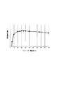
図2は、インバーター104A,104Bの負荷率による電力変換効率の変化特性の一例を示す。図2の横軸はインバーター負荷率を示し、縦軸は電力変換効率を示す。但し、電力変換効率については、単にその傾向のみを示している。
図2に示すように、電力変換効率は、インバーター負荷率が10%以下の非常に低い状態では低く、インバーター負荷率が約30%になるまでインバーター負荷率の上昇に伴って電力変換効率が高くなる。電力変換効率のピークは、インバーター負荷率が約30%から約40%の範囲であり、40%よりもインバーター負荷率が高くなるに従って、電力変換効率が徐々に低くなる。
[2. Example of inverter conversion efficiency]
FIG. 2 shows an example of a change characteristic of the power conversion efficiency depending on the load factor of the
As shown in FIG. 2, the power conversion efficiency is low when the inverter load factor is very low, 10% or less, and the power conversion efficiency increases as the inverter load factor increases until the inverter load factor reaches about 30%. Become. The peak of the power conversion efficiency is in the range where the inverter load factor is about 30% to about 40%, and the power conversion efficiency gradually decreases as the inverter load factor becomes higher than 40%.
したがって、電力変換効率に着目した場合には、各インバーター104A,104Bは、インバーター負荷率が10%以下になることを避けるのが好ましい。また、より高い効率で運転する場合には、負荷率が約30%から約40%の範囲であるのが好ましい。但し、この範囲は一例であり、電力変換効率が最も高くなる負荷率の範囲は、インバーターの形式によって異なる。
蓄電池監視制御装置103が各蓄電池106A,106Bでの充電又は放電を組み合わせた負荷分散制御を行う際には、制御要因の1つとして、この電力変換効率に着目する。蓄電池監視制御装置103が負荷分散制御を行う際に着目する他の制御要因については後述する。
Therefore, when paying attention to the power conversion efficiency, it is preferable that the
When the storage battery
[3.蓄電池監視制御装置による制御処理例]
図3のフローチャートは、蓄電池監視制御装置103による複数の蓄電池106A,106Bの充放電を制御する処理例を示す。
まず、蓄電池監視制御装置103は、リモート監視制御装置102からの充放電指令情報PXにより、充電又は放電の指示があるか否かを判断する(ステップS11)。充電又は放電の指示がない場合には(ステップS11のNO)、充放電指令情報PXが供給されるまで待機する。
[3. Example of control processing by storage battery monitoring and control device]
The flowchart of FIG. 3 shows a processing example for controlling charging / discharging of the plurality of storage batteries 106 </ b> A and 106 </ b> B by the storage battery
First, the storage battery
充電又は放電の指示がある場合(ステップS11のYES)、蓄電池監視制御装置103は、現在の蓄電池106A,106Bの充電量が、第1閾値と第2閾値との間で管理可能な状態か否かを判断する(ステップS12)。ここでの第1閾値と第2閾値との間で管理可能な状態とは、例えば充電指示があるときに、第1閾値を超えた充電残量の蓄電池がある場合、あるいは、放電指示があるときに、第2閾値未満の充電残量の蓄電池がある場合に相当する。
ここで、第1閾値と第2閾値との間で管理可能な状態でない場合には(ステップS12のNO)、蓄電池監視制御装置103は、SOC上限値までの充電又はSOC下限値までの放電により、蓄電池106A,106Bを充放電する(ステップS13)。ステップS13での充電又は放電を開始した後、充電状況又は放電状況に変化があったときには、蓄電池監視制御装置103はステップS11の判断に戻る。
When there is an instruction for charging or discharging (YES in step S11), the storage battery
Here, when the state is not manageable between the first threshold value and the second threshold value (NO in step S12), the storage battery
ステップS12で、第1閾値と第2閾値との間で管理可能な状態であると判断した場合には(ステップS12のYES)、複数の蓄電池106A,106Bの充放電負荷を分散させた上で、第1閾値と第2閾値との間で充電又は放電を行う(ステップS14)。ここでの充放電負荷分散制御例は後述するが、単純に複数の蓄電池に充電や放電を分散させる以外に、充電時に一部の蓄電池を放電させる制御や、放電時に一部の蓄電池を充電させる制御を行う場合もある。
ステップS14での負荷分散制御が行われた状態での充電又は放電を開始した後、蓄電池監視制御装置103は、現在の負荷分散制御状態による蓄電池の組み合わせが適正か否かを判断する(ステップS15)。ここで、組み合わせが適正でない状況が発生した場合には(ステップS15のNO)、蓄電池監視制御装置103は、複数の蓄電池106A,106Bの充放電の組み合わせを変更して(ステップS16)、ステップS14の負荷分散制御状態に戻る。
また、組み合わせが適正である場合には(ステップS15のYES)、蓄電池監視制御装置103はステップS11の判断に戻る。
If it is determined in step S12 that the state can be managed between the first threshold value and the second threshold value (YES in step S12), the charge / discharge loads of the plurality of
After starting charging or discharging in the state where the load distribution control is performed in step S14, the storage battery
If the combination is appropriate (YES in step S15), the storage battery
なお、この図3のフローチャートに示す制御例では、蓄電池監視制御装置103は、各蓄電池106A,106Bの充電残量が第1閾値と第2閾値の間のとき、ステップS14で負荷分散制御を行うようにした。これに対して、ステップS13でのSOC上限値までの充電やSOC下限値までの放電を行う際にも、蓄電池監視制御装置103は、負荷分散制御を行うようにしてもよい。
In the control example shown in the flowchart of FIG. 3, the storage battery
[4.具体的な充放電例]
図4は、2つの蓄電池106A,106Bを使って負荷分散制御を行う1つの例を示す。
ここでは、2つの蓄電池106A,106Bは同じ特性及び容量であり、SOC上限値を85%、SOC下限値を15%、第1閾値を60%、第2閾値を40%に設定した例である。図4において、縦軸は各蓄電池106A,106Bの充電残量であり、横軸は時間である。図4中で、実線の特性SOC1が一方の蓄電池106Aの充電残量を示し、破線の特性SOC2が他方の蓄電池106Bの充電残量を示す。また、図4中に二点差線で示す放電量IV1,IV2は、インバーター104A,104Bで変換した電力の積算量を示す。
[4. Specific charge / discharge example]
FIG. 4 shows an example in which load distribution control is performed using two
Here, the two
図4は、リモート監視制御装置102から放電指令が蓄電池監視制御装置103に届いた状態であって、各蓄電池106A,106Bは、いずれも充電残量が第1閾値(60%)で待機した状態を示している。そして、必要な放電量は、1個の蓄電池106Aの放電で確保でき、かつ負荷分散制御の点から蓄電池106Aだけを放電させるのが好ましいとする。この場合、蓄電池監視制御装置103は、蓄電池106Aを放電するように、インバーター104Aに充放電指令P1を送る。この充放電指令P1により、図4の期間t1での放電IV1が行われ、実線で示すように、蓄電池106Aの充電残量SOC1が徐々に低下する。
FIG. 4 shows a state in which a discharge command has arrived from the remote
そして、放電開始から所定期間(図4の期間t1)放電が継続することで、蓄電池106Aの充電残量SOC1が、第2閾値(40%)未満に低下したとする。このとき、蓄電池監視制御装置103は、蓄電池106Aの放電を停止し、別の蓄電池106Bの放電を開始する。蓄電池106Bの放電を開始するために、蓄電池監視制御装置103は、インバーター104Bに充放電指令P2を送る。この充放電指令P2により、図4の期間t2に示す放電IV2が行われ、破線で示すように、蓄電池106Bの充電残量SOC2が徐々に低下する。
Then, it is assumed that the remaining charge SOC1 of the
ここでは、蓄電池監視制御装置103は、蓄電池106Bの放電時に、インバーター104Aが充電用として作動するように充放電指令P1を送り、蓄電池106Bから放電した電流で蓄電池106Aを充電する。この充電により、第2閾値未満に低下した蓄電池106Aの充電残量SOC1が、第1閾値と第2閾値の間の範囲内に復帰する。
Here, the storage battery
そして、蓄電池106Aの充電残量SOC1がある程度の値(例えば50%)になると、蓄電池監視制御装置103は、インバーター104Aが放電用として作動するように充放電指令P1を送り、蓄電池106Aを放電する。この充放電指令P1により、図4の期間t3での放電IV1が行われる。
このようにして、蓄電池監視制御装置103が、2つの蓄電池106A,106Bを交互に作動させる負荷分散処理を制御する。
When the remaining charge SOC1 of the
In this way, the storage battery
[5.負荷分散処理時の判断要因の例]
次に、蓄電池監視制御装置103が負荷分散処理を実行する際の判断要因の例を説明する。
図5は、インバーター104A,104Bの変換効率から負荷分散処理状態を判断する処理例を示すフローチャートである。
まず、蓄電池監視制御装置103は、現在作動中の状態よりも変換効率が高くなる別の蓄電池(インバーター)の組み合わせがあるか否かを判断する(ステップS21)。ここで、現在作動中の組み合わせより変換効率が高くなる別の組み合わせがないと判断した場合には(ステップS21のNO)、蓄電池監視制御装置103は、現在の組み合わせを継続し、ステップS21の判断を繰り返し行う。
[5. Example of judgment factors during load balancing processing]
Next, an example of a determination factor when the storage battery
FIG. 5 is a flowchart illustrating a processing example for determining the load distribution processing state from the conversion efficiency of the
First, the storage battery
そして、現在作動中の組み合わせより変換効率が高くなる別の組み合わせが存在する場合には(ステップS21のYES)、蓄電池監視制御装置103は、充電又は放電する蓄電池の組み合わせを変更する(ステップS22)。ここでの組み合わせの変更には、作動中の各インバーター104A,104Bの負荷率の変更も含まれる。
ステップS22で充電又は放電する蓄電池の組み合わせを変更した後、ステップS21の判断に戻る。
このようにすることで、変換効率が常に高い状態で充電及び放電が行われるようになる。
And when there exists another combination whose conversion efficiency becomes higher than the combination currently actuated (YES of step S21), the storage battery
After changing the combination of storage batteries to be charged or discharged in step S22, the process returns to the determination in step S21.
By doing in this way, charging and discharging are performed in a state where the conversion efficiency is always high.
図6は、インバーター104A,104Bの累積充放電時間から負荷分散処理状態を判断して、インバーター104A,104Bの累積充放電時間をほぼ均等にする処理例を示すフローチャートである。
まず、蓄電池監視制御装置103は、現在のインバーター104A,104Bの累積充放電時間に偏りがあるか否かを判断する(ステップS31)。ここで、現在のインバーター104A,104Bの累積充放電時間に偏りがないと判断した場合には(ステップS31のNO)、蓄電池監視制御装置103は、現在の組み合わせを継続し、ステップS31の判断を繰り返す。
FIG. 6 is a flowchart showing a processing example in which the load distribution processing state is determined from the cumulative charge / discharge times of the
First, the storage battery
そして、現在の累積充放電時間に偏りがある場合には(ステップS31のYES)、蓄電池監視制御装置103は、累積充放電時間が少ないインバーターを優先的に使うように、充電又は放電する蓄電池の組み合わせを変更する(ステップS32)。ステップS32で充電又は放電する蓄電池の組み合わせを変更した後、ステップS31の判断に戻る。このようにすることで、インバーターや蓄電池の累積充放電時間がほぼ均等になる。
If there is a bias in the current accumulated charge / discharge time (YES in step S31), the storage battery
蓄電池監視制御装置103は、これらの要因ごとの最適な負荷分散状態を総合的に判断して、実際に設定する負荷分散状態を決める。このとき、蓄電池監視制御装置103は、例えばそれぞれの要因ごとに優先度を決めて、優先度の高い要因をより反映させた負荷分散状態を行うようにしてもよい。なお、変換効率と累積充放電時間の2つの要因を使うのは一例であり、蓄電池監視制御装置103は、その他の要因を加えて負荷分散状態を決めるようにしてもよい。
The storage battery
このように本例の蓄電池システム100によると、蓄電池106A,106B及びインバーター104A,104Bが適切に分散して使用されると共に、蓄電池106A,106Bの充電残量が適切に管理される。したがって、蓄電システム全体としてのパフォーマンスの向上及び蓄電池の寿命の長寿命化を図ることができる。例えば、蓄電池106Aの充電量が第1閾値に達したとき、別の蓄電池106Bの充電量を調整して、SOC上限値に到達するのを防ぐ運用が可能になり、SOC上限値やSOC下限値に達する回数を減少させる運用が可能になる。また、複数の蓄電池106A,106Bの累積充放電時間の偏りを防ぐこともできるようになり、蓄電システム全体としてのパフォーマンスの向上や蓄電池の寿命の長寿命化を図ることができる。
As described above, according to the
しかも、本例の蓄電池システム100の場合には、複数の蓄電池106A,106Bの特性や容量がどのような組み合わせであっても適用が可能であり、複数の蓄電池を備えた種々の蓄電池システムに適用できるようになる。具体的には、複数の蓄電池106A,106Bは、特性や容量が同じである場合と、相違した場合のいずれであっても、本例の蓄電池システム100に適用が可能になる。このため、新規に作成する蓄電池システムに適用できることは勿論であるが、既存の蓄電池システムに、蓄電池監視制御装置103が行う制御機能を追加することでも適用できるようになる。
In addition, in the case of the
[6.閾値を変更する例]
ここまでの説明では、SOC上限値やSOC下限値との間に設定する第1閾値及び第2閾値は、60%と40%に設定する例とした。これに対して、第1閾値と第2閾値は、そのときの状況に応じて可変設定するようにしてもよい。
図7は、蓄電池監視制御装置103が第1閾値と第2閾値を可変設定する処理例を示すフローチャートである。
[6. Example of changing threshold]
In the description so far, the first threshold value and the second threshold value set between the SOC upper limit value and the SOC lower limit value are set to 60% and 40%. On the other hand, the first threshold value and the second threshold value may be variably set according to the situation at that time.
FIG. 7 is a flowchart illustrating a processing example in which the storage battery
まず蓄電池監視制御装置103は、電力系統101の状況と蓄電池システム100の状況から現在(又は近い将来)の需給バランスに変化があるか否かを判断する(ステップS41)。ここで、需給バランスに変化がないと判断したときには(ステップS41のNO)、各閾値を変更せずにそのまま待機する。
First, the storage battery monitoring and
そして、需給バランスに変化があると判断したとき、蓄電池監視制御装置103は、現在(又は予想される)需給バランスに基づいて第1閾値と第2閾値を、SOC上限値やSOC下限値との間で再設定する閾値設定処理を行う(ステップS42)。そして、蓄電池監視制御装置103は、その再設定した第1閾値と第2閾値で負荷分散制御を行う。その後、蓄電池監視制御装置103は、ステップS41の判断処理に戻る。
When determining that there is a change in the supply-demand balance, the storage battery
ステップS41での需給バランスの変化とは、例えば、電力系統101に接続された負荷機器が多く作動して、電力消費が増える状況になった場合や、電力系統101に接続された発電所(太陽光、風力など)での発電量が増える状況になった場合などが想定される。
また、予想される需給バランスとしては、特定の時間に稼働する機器がある場合や、天気予報などから発電量の変化が予想される場合などがある。
The change in the supply and demand balance in step S41 is, for example, when a large number of load devices connected to the
Moreover, as an expected supply and demand balance, there is a case where there is a device that operates at a specific time, and a case where a change in power generation amount is predicted from a weather forecast or the like.
このように需給バランスの変化に基づいて第1閾値と第2閾値を可変設定することで、各蓄電池106A,106Bを適切に負荷分散制御できる範囲が可変し、そのときの需給バランスに基づいた適切な運用が可能になる。
Thus, by variably setting the first threshold value and the second threshold value based on the change in the supply and demand balance, the range in which each
[7.変形例]
なお、本発明は上述した実施の形態例に限定されるものではなく、様々な変形例又は応用例が含まれる。例えば、上述した実施の形態例は本発明を分かりやすく説明するために詳細に説明したものであり、必ずしも図1などで説明した全ての構成を備えるものに限定されるものではない。
[7. Modified example]
Note that the present invention is not limited to the above-described embodiments, and includes various modifications and application examples. For example, the above-described embodiment has been described in detail for easy understanding of the present invention, and is not necessarily limited to the one having all the configurations described in FIG.
また、図1に示す構成では、説明を簡単にするために2組の蓄電池106A,106Bと2組のインバーター104A,104Bを備えたものとしたが、本発明は、3組以上の多数の蓄電池やインバーターを備えた蓄電システムに適用可能である。
Further, in the configuration shown in FIG. 1, two sets of
また、上記の各構成、機能、処理部、処理手段等は、それらの一部又は全部を、例えば集積回路で設計する等によりハードウェアで実現してもよい。また、上記の各構成、機能などは、プロセッサがそれぞれの機能を実現するプログラムを解釈し、実行することによりソフトウェアで実現してもよい。各機能を実現するプログラム、テーブル、ファイル等の情報は、メモリや、ハードディスク、SSD(Solid State Drive)等の記録装置、または、ICカード、SDカード、DVD等の記録媒体に置くことができる。
また、制御線や情報線は説明上必要と考えられるものを示しており、製品上必ずしも全ての制御線や情報線を示しているとは限らない。実際には殆ど全ての構成が相互に接続されていると考えてもよい。
Each of the above-described configurations, functions, processing units, processing means, and the like may be realized by hardware by designing a part or all of them with, for example, an integrated circuit. Each of the above-described configurations, functions, and the like may be realized by software by interpreting and executing a program that realizes each function by the processor. Information such as programs, tables, and files for realizing each function can be stored in a recording device such as a memory, a hard disk, an SSD (Solid State Drive), or a recording medium such as an IC card, an SD card, or a DVD.
Further, the control lines and information lines indicate what is considered necessary for the explanation, and not all the control lines and information lines on the product are necessarily shown. Actually, it may be considered that almost all the components are connected to each other.
100…蓄電池システム、101…電力系統、102…リモート監視制御装置、103…蓄電池監視制御装置、104A,104B…インバーター、105A,105B…直流ライン、106A,106B…蓄電池、107…交流ライン
DESCRIPTION OF
Claims (6)
前記蓄電池監視制御装置は、それぞれの前記蓄電池の充電量として、蓄電池の充電容量から決まる上限充電量と下限充電量との間に、第1閾値と前記第1閾値よりも小さな充電量の第2閾値を設定し、それぞれの前記蓄電池が、前記第1閾値と前記第2閾値の間の充電量が優先的に設定されるように、複数の前記蓄電池での充電又は放電を組み合わせた負荷分散制御を行う
蓄電池システム。 A plurality of storage batteries that are individually connected to each other and can be charged and discharged individually, and a storage battery monitor that individually monitors a charge amount of the plurality of storage batteries and gives a charge command or a discharge command to the plurality of storage batteries individually A storage battery system comprising a control device,
The storage battery monitoring and control device has a first threshold value and a second charge amount smaller than the first threshold value between the upper limit charge amount and the lower limit charge amount determined from the charge capacity of the storage battery as the charge amount of each storage battery. Load balancing control combining charging or discharging of a plurality of the storage batteries so that a threshold value is set and each of the storage batteries is preferentially set with a charge amount between the first threshold value and the second threshold value Do a storage battery system.
請求項1に記載の蓄電池システム。 The storage battery system according to claim 1, wherein the load distribution control by the storage battery monitoring control device is charged by the specific storage battery and simultaneously discharged by the storage battery other than the specific storage battery.
請求項1に記載の蓄電池システム。 The said storage battery monitoring control apparatus performs control which preferentially uses the load factor in the predetermined range with high power conversion efficiency in the said inverter combining the charge or discharge in the said some storage battery. Storage battery system.
請求項1に記載の蓄電池システム。 The storage battery system according to claim 1, wherein the storage battery monitoring and control device performs control such that cumulative charge / discharge times in the plurality of inverters are substantially equal by combining charging or discharging in the plurality of storage batteries.
請求項1〜4のいずれか1項に記載の蓄電池システム。 The said storage battery monitoring control apparatus acquires the information regarding the supply-and-demand balance of the connected electric power grid | system, and variably sets the said 1st threshold value and the said 2nd threshold value based on the information regarding the acquired supply-and-demand balance. The storage battery system according to any one of the above.
それぞれの前記蓄電池の充電量として、蓄電池の充電容量から決まる上限充電量と下限充電量との間に、第1閾値と前記第1閾値よりも小さな充電量の第2閾値を設定する閾値設定処理と、
それぞれの前記蓄電池が、前記第1閾値と前記第2閾値の間の充電量が優先的に設定されるように、複数の前記蓄電池での充電又は放電を組み合わせた負荷分散制御を行う負荷分散制御処理とを含む
蓄電池制御方法。 A storage battery control method that individually gives a charge command or a discharge command to a plurality of storage batteries that can be individually charged and discharged by being individually connected to an inverter.
Threshold setting processing for setting a first threshold value and a second threshold value with a charge amount smaller than the first threshold value between the upper limit charge amount and the lower limit charge amount determined from the charge capacity of the storage battery as the charge amount of each storage battery When,
Load balancing control that performs load balancing control that combines charging or discharging of the plurality of storage batteries so that each of the storage batteries is preferentially set with a charge amount between the first threshold value and the second threshold value. A storage battery control method including processing.
Priority Applications (1)
| Application Number | Priority Date | Filing Date | Title |
|---|---|---|---|
| JP2016077011A JP2017189045A (en) | 2016-04-07 | 2016-04-07 | Storage battery system and storage battery control method |
Applications Claiming Priority (1)
| Application Number | Priority Date | Filing Date | Title |
|---|---|---|---|
| JP2016077011A JP2017189045A (en) | 2016-04-07 | 2016-04-07 | Storage battery system and storage battery control method |
Publications (1)
| Publication Number | Publication Date |
|---|---|
| JP2017189045A true JP2017189045A (en) | 2017-10-12 |
Family
ID=60045082
Family Applications (1)
| Application Number | Title | Priority Date | Filing Date |
|---|---|---|---|
| JP2016077011A Pending JP2017189045A (en) | 2016-04-07 | 2016-04-07 | Storage battery system and storage battery control method |
Country Status (1)
| Country | Link |
|---|---|
| JP (1) | JP2017189045A (en) |
Cited By (3)
| Publication number | Priority date | Publication date | Assignee | Title |
|---|---|---|---|---|
| WO2019123529A1 (en) * | 2017-12-19 | 2019-06-27 | 東芝三菱電機産業システム株式会社 | Storage battery system and operating method therefor |
| CN111162550A (en) * | 2019-12-18 | 2020-05-15 | 安徽天尚清洁能源科技有限公司 | Micro-grid complementary power supply method through storage battery transition |
| JPWO2021074976A1 (en) * | 2019-10-15 | 2021-04-22 |
Citations (4)
| Publication number | Priority date | Publication date | Assignee | Title |
|---|---|---|---|---|
| JP2010097760A (en) * | 2008-10-15 | 2010-04-30 | Mitsubishi Heavy Ind Ltd | Electric energy storage system |
| WO2011016273A1 (en) * | 2009-08-04 | 2011-02-10 | 日本電気株式会社 | Energy system |
| JP2014030334A (en) * | 2012-06-29 | 2014-02-13 | Sekisui Chem Co Ltd | Power management device, power management method, and program |
| JP2014233096A (en) * | 2011-09-27 | 2014-12-11 | 三洋電機株式会社 | Charge and discharge system |
-
2016
- 2016-04-07 JP JP2016077011A patent/JP2017189045A/en active Pending
Patent Citations (4)
| Publication number | Priority date | Publication date | Assignee | Title |
|---|---|---|---|---|
| JP2010097760A (en) * | 2008-10-15 | 2010-04-30 | Mitsubishi Heavy Ind Ltd | Electric energy storage system |
| WO2011016273A1 (en) * | 2009-08-04 | 2011-02-10 | 日本電気株式会社 | Energy system |
| JP2014233096A (en) * | 2011-09-27 | 2014-12-11 | 三洋電機株式会社 | Charge and discharge system |
| JP2014030334A (en) * | 2012-06-29 | 2014-02-13 | Sekisui Chem Co Ltd | Power management device, power management method, and program |
Cited By (6)
| Publication number | Priority date | Publication date | Assignee | Title |
|---|---|---|---|---|
| WO2019123529A1 (en) * | 2017-12-19 | 2019-06-27 | 東芝三菱電機産業システム株式会社 | Storage battery system and operating method therefor |
| JPWO2021074976A1 (en) * | 2019-10-15 | 2021-04-22 | ||
| WO2021074976A1 (en) * | 2019-10-15 | 2021-04-22 | 株式会社東芝 | Power storage system and control method |
| JP7458408B2 (en) | 2019-10-15 | 2024-03-29 | 株式会社東芝 | Power storage system and control method |
| CN111162550A (en) * | 2019-12-18 | 2020-05-15 | 安徽天尚清洁能源科技有限公司 | Micro-grid complementary power supply method through storage battery transition |
| CN111162550B (en) * | 2019-12-18 | 2024-03-29 | 安徽尚特杰电力技术有限公司 | Micro-grid complementary power supply method through storage battery transition |
Similar Documents
| Publication | Publication Date | Title |
|---|---|---|
| US11669144B2 (en) | Methods and systems for distributed power control of flexible datacenters | |
| KR101661704B1 (en) | Microgrid energy management system and power storage method of energy storage system | |
| JP2013192327A (en) | Storage battery control device, storage battery control method, program, electricity storage system, and power supply system | |
| US8084994B2 (en) | System to extend the service life of portable devices | |
| CN112585837A (en) | Enhanced battery management system for battery packs | |
| US20190148956A1 (en) | Control of parallel battery utilization | |
| US10211667B2 (en) | Uninterrupted power supply systems and methods | |
| EP3850462A1 (en) | System of critical datacenters and behind-the-meter flexible datacenters | |
| JP6430775B2 (en) | Storage battery device | |
| JP2013179729A (en) | Storage battery control device, storage battery control method, program, power storage system and power supply system | |
| JP6166338B2 (en) | Energy storage system | |
| US20160190821A1 (en) | Energy storage system, method and apparatus for controlling charging and discharging of the same | |
| WO2017101453A1 (en) | Power supply control method and apparatus | |
| US20150263564A1 (en) | Energy storage system and method for driving the same | |
| JP2017189045A (en) | Storage battery system and storage battery control method | |
| JP2016226120A (en) | Power conditioner operation controller, operation control method, operation control program, and photovoltaic system | |
| CN106159980B (en) | Power generation system and energy management method | |
| KR102243021B1 (en) | Hybrid energy storage system and method of contolling the same | |
| US9450417B2 (en) | Method for efficiency-driven operation of dispatchable sources and storage units in energy systems | |
| JP2014236602A (en) | Multiple purpose controller, multiple purpose control system and program of multiple storage batteries | |
| KR20210055283A (en) | Method for controlling grid sustaining and distribution operation of distributed resources and apparatus thereof | |
| WO2013162500A1 (en) | Moderating a charging | |
| US20160359327A1 (en) | Microgrid system and control method for the same | |
| EP3567691B1 (en) | Composite power storage system and power storage method | |
| JP6482170B2 (en) | Energy management system, power system, energy management method, and program |
Legal Events
| Date | Code | Title | Description |
|---|---|---|---|
| A621 | Written request for application examination |
Free format text: JAPANESE INTERMEDIATE CODE: A621 Effective date: 20180918 |
|
| A977 | Report on retrieval |
Free format text: JAPANESE INTERMEDIATE CODE: A971007 Effective date: 20190612 |
|
| A131 | Notification of reasons for refusal |
Free format text: JAPANESE INTERMEDIATE CODE: A131 Effective date: 20190716 |
|
| A02 | Decision of refusal |
Free format text: JAPANESE INTERMEDIATE CODE: A02 Effective date: 20200128 |