JP2009055081A - Wearable automatic imaging apparatus, image tilt correction method, and image tilt correction system and program - Google Patents
Wearable automatic imaging apparatus, image tilt correction method, and image tilt correction system and program Download PDFInfo
- Publication number
- JP2009055081A JP2009055081A JP2007216985A JP2007216985A JP2009055081A JP 2009055081 A JP2009055081 A JP 2009055081A JP 2007216985 A JP2007216985 A JP 2007216985A JP 2007216985 A JP2007216985 A JP 2007216985A JP 2009055081 A JP2009055081 A JP 2009055081A
- Authority
- JP
- Japan
- Prior art keywords
- image data
- captured image
- tilt
- correction
- amount
- Prior art date
- Legal status (The legal status is an assumption and is not a legal conclusion. Google has not performed a legal analysis and makes no representation as to the accuracy of the status listed.)
- Pending
Links
Images


Landscapes
- Indication In Cameras, And Counting Of Exposures (AREA)
- Image Processing (AREA)
- Television Signal Processing For Recording (AREA)
- Studio Devices (AREA)
Abstract
Description
本発明は、使用者に装着され被写体を自動撮像する装着型自動撮像装置と画像傾き補正方法に関する。また、装着型自動撮像装置と情報処理装置とを備えて構成される画像傾き補正システム、及び情報処理装置にて実行されるべきプログラムに関する。 The present invention relates to a wearable automatic imaging apparatus and an image tilt correction method that are worn by a user and automatically image a subject. The present invention also relates to an image tilt correction system including a wearable automatic imaging apparatus and an information processing apparatus, and a program to be executed by the information processing apparatus.
例えばライフログカメラとして、ユーザが装着しているカメラが自動的に定期的な画像撮像を行うことで、ユーザが日常生活で目にする光景を画像データとして記録するカメラが提案されている。このライフログカメラを使用することで、ユーザの行動履歴や思い出などを、画像データとして残すことが可能となる。
具体的に、ライフログカメラとしては、例えばネックストラップによって首から吊り下げられたり、眼鏡型の装着ユニットと一体的に形成されるなどしてユーザに装着されることになる。そして、このような装着状態において、例えば一定時間間隔で撮像を行い、撮像画像を保存するようにされる。
For example, as a life log camera, a camera that records a scene that the user sees in daily life as image data by automatically taking a periodic image with a camera worn by the user has been proposed. By using this life log camera, it becomes possible to leave a user's action history, memories, etc. as image data.
Specifically, as a life log camera, for example, it is suspended from the neck by a neck strap, or is integrally formed with a spectacle-type mounting unit, and is mounted on the user. In such a wearing state, for example, imaging is performed at regular time intervals, and the captured images are stored.
なお、関連する従来技術については下記特許文献を挙げることができる。
上記のようなライフログカメラで画像を自動撮像して保存する目的は、保存された画像を再生表示することによってユーザが自身の行動履歴を確認したり、思い出を呼び起こすといったところにある。
ここで、上述のようにして日常の光景を一定間隔で撮像するという性質上、ライフログカメラでは、撮像画像が大量に保存されることが想定される。これに伴い、保存画像を再生する際には、通常のカメラ装置(使用者のシャッター操作(セルフタイマ撮像も含む)などにより撮像を行うカメラ装置)による撮像画像を再生表示する場合とは異なり、保存画像を比較的高速に(パラパラと)送り表示させるといった使用法が想定されている。
The purpose of automatically capturing and storing an image with the life log camera as described above is that the user can confirm his / her action history or evoke memories by reproducing and displaying the stored image.
Here, due to the property of capturing a daily scene at regular intervals as described above, it is assumed that a large number of captured images are stored in the lifelog camera. Along with this, when playing back saved images, unlike when playing back and displaying captured images from normal camera devices (camera devices that capture images by a user's shutter operation (including self-timer imaging)), It is assumed that the stored image is sent and displayed at a relatively high speed.
しかしながら、ライフログカメラはユーザに装着された状態で撮像を行うようにされることから、ユーザの歩行や動作に伴って装置本体の傾きが比較的大きく変動することが懸念され、これに伴い、撮像画像としてもその傾きが大きくばらつくものとなってしまうことが懸念される。
このように撮像画像に比較的大きな傾きのバラツキが生じてしまった場合、上述のようにして保存画像を送り再生する際には、再生画像が不自然に揺れてしまうという現象が起こる。特に、ライフログカメラによる撮像画像については上述のように比較的高速な送り再生が行われることになるので、画像傾きに伴う再生画像の揺れが生じた場合、ユーザに対して非常に大きな不快感を与えてしまう可能性が高まる。
However, since the lifelog camera is to be imaged while being worn by the user, there is a concern that the inclination of the apparatus main body may vary relatively with the walking and operation of the user. There is a concern that the inclination of the captured image may vary greatly.
In this way, when the captured image has a relatively large variation in inclination, a phenomenon occurs in which the reproduced image is unnaturally shaken when the stored image is transmitted and reproduced as described above. In particular, the images captured by the lifelog camera are fed and played at a relatively high speed as described above. Therefore, when the playback image is shaken due to the tilt of the image, the user feels very uncomfortable. Increases the possibility of giving
本発明では以上のような問題点に鑑み、使用者に装着され被写体を自動撮像する装着型自動撮像装置において、保存された撮像画像データの再生時に生じる可能性のある再生画像の揺れの発生の防止を図ることを目的とする。
このような目的の達成を図るべく、本発明では、装着型自動撮像装置として以下のように構成することとした。
つまり、本発明の装着型自動撮像装置は、被写体を撮像して撮像画像データを得る撮像手段と、上記撮像手段により得られる撮像画像データを使用者の操作に基づかず自動的に取り込む撮像画像自動取得手段とを備える。
また、上記撮像画像自動取得手段により取り込まれた撮像画像データの傾き量を検出する傾き量検出手段と、上記撮像画像自動取得手段により取り込まれた撮像画像データの傾きを上記傾き量検出手段により検出された傾き量の情報に基づいて補正する傾き補正手段とを備えるものである。
In the present invention, in view of the above-described problems, in a wearable automatic imaging device that is worn by a user and automatically images a subject, occurrence of a shake of a reproduced image that may occur during reproduction of stored captured image data The purpose is to prevent it.
In order to achieve such an object, in the present invention, the wearable automatic imaging apparatus is configured as follows.
That is, the wearable automatic image pickup apparatus of the present invention has an image pickup means for picking up a picked-up image data by picking up an image of a subject, and a picked-up image automatic pick-up image automatically obtained based on a user's operation. Acquisition means.
Further, an inclination amount detecting means for detecting an inclination amount of the captured image data captured by the captured image automatic acquisition means, and an inclination of the captured image data captured by the captured image automatic acquisition means are detected by the inclination amount detecting means. And an inclination correction means for correcting based on the information on the amount of inclination.
また、本発明では画像傾き補正システムとして以下のように構成することとした。
つまり、本発明の画像傾き補正システムは、使用者に装着され被写体を自動撮像する装着型自動撮像装置と、上記装着型自動撮像装置との間でデータ通信を行うことが可能に構成された情報処理装置とを備えて構成されるものであって、
上記装着型自動撮像装置が、
被写体を撮像して撮像画像データを得る撮像手段と、上記撮像手段により得られる撮像画像データを使用者の操作に基づかず自動的に取り込む撮像画像自動取得手段とを備える。
また、上記撮像画像自動取得手段により取り込まれた撮像画像データの傾き量を検出する傾き量検出手段と、上記撮像画像自動取得手段により取り込まれた撮像画像データと上記傾き量検出手段により検出された傾き量の情報を撮像装置側記録媒体に記録する撮像装置側記録手段とを備える。
また、上記情報処理装置が、
情報処理装置側記録媒体に対する記録を行う情報処理装置側記録手段と、制御手段とを備える。
そして、上記制御手段が、
上記撮像装置側記録媒体に記録された上記撮像画像データと上記傾き量の情報を取り込み、上記情報処理装置側記録手段によって上記情報処理装置側記録媒体に記録させるデータ取込・記録制御処理と、
上記情報処理装置側記録媒体に記録された上記撮像画像データの傾きを、上記情報処理装置側記録媒体に記録された傾き量の情報に基づいて補正する傾き補正処理とを実行するものである。
In the present invention, the image tilt correction system is configured as follows.
In other words, the image tilt correction system of the present invention is configured so that data communication can be performed between a wearable automatic imaging apparatus that is worn by a user and automatically captures a subject and the wearable automatic imaging apparatus. Comprising a processing device,
The wearable automatic imaging device is
An image pickup means for picking up an image of a subject to obtain picked-up image data, and a picked-up image automatic acquisition means for automatically taking in the picked-up image data obtained by the image pickup means without any user operation.
Further, an inclination amount detecting means for detecting an inclination amount of the captured image data captured by the captured image automatic acquisition means, and the captured image data captured by the captured image automatic acquisition means and the inclination amount detecting means. An image pickup apparatus side recording unit that records information on the amount of inclination on the image pickup apparatus side recording medium.
In addition, the information processing apparatus
An information processing apparatus side recording unit that performs recording on the information processing apparatus side recording medium and a control unit are provided.
And the control means is
A data capturing / recording control process for capturing the captured image data recorded on the imaging device-side recording medium and information on the tilt amount, and recording the information on the information processing device-side recording medium by the information processing device-side recording unit;
An inclination correction process for correcting the inclination of the captured image data recorded on the information processing apparatus side recording medium based on the information of the inclination amount recorded on the information processing apparatus side recording medium is executed.
上記のようにして本発明は、自動撮像された撮像画像データ(自動撮像画像データ)についてその傾き量を検出し、検出された傾き量の情報に基づき自動撮像画像データの傾き補正を行うものである。 As described above, the present invention detects the tilt amount of automatically captured image data (automatically captured image data), and corrects the tilt of the automatically captured image data based on the detected tilt amount information. is there.
上記本発明により、例えばライフログカメラなど、使用者に装着され被写体を自動撮像する装着型自動撮像装置により自動撮像された撮像画像データについて、その傾きの補正を行うことができる。
これによれば、撮像画像データに基づく再生画像の揺れを効果的に防止することができ、ユーザに不快感を与えてしまうといった事態の発生の防止を図ることができる。
According to the present invention, it is possible to correct the inclination of captured image data automatically captured by a wearable automatic imaging apparatus that automatically images a subject attached to a user, such as a life log camera.
According to this, it is possible to effectively prevent the playback image based on the captured image data from being shaken, and to prevent the occurrence of a situation in which the user is uncomfortable.
また、本発明としては、装着型自動撮像装置側にて撮像画像データとその傾き情報を所要の記録媒体に記録することもできるが、このようにすれば、オリジナルの撮像画像データを保存しておくことができるという効果を得ることができると共に、記録された傾き量の情報に基づいて撮像画像データの補正が可能となるようにできるという効果を得ることができる。 Further, according to the present invention, it is possible to record the captured image data and the inclination information thereof on a required recording medium on the wearable automatic imaging device side, but in this way, the original captured image data is stored. The effect that the captured image data can be corrected based on the recorded tilt amount information can be obtained.
以下、発明を実施するための最良の形態(以下実施の形態とする)について説明していく。
<第1の実施の形態>
[装着型自動撮像装置の外観例]
図1は、本発明の装着型自動撮像装置の一実施形態としての、撮像装置1の外観例を示している。
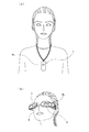
図1(a)は、首かけタイプ(ネックストラップタイプ)による撮像装置1の外観例を示している。この場合の撮像装置1は、例えばストラップを取り付ける部位を持ち、この部位にストラップを取り付けて図示するようにユーザの首にかけることで装着される。ユーザは、撮像装置1が備える撮像レンズ3Lがユーザの正面方向を被写体方向として撮像出来るように装着すればよい。
なお、図示していないが、例えば撮像装置1の背面部などに、撮像モニタ用や撮像画像の再生などに用いる表示部が設けられてもよい。
Hereinafter, the best mode for carrying out the invention (hereinafter referred to as an embodiment) will be described.
<First Embodiment>
[Appearance example of wearable automatic imaging device]
FIG. 1 shows an appearance example of an
FIG. 1A shows an example of the appearance of an
Although not shown, for example, a display unit used for an imaging monitor or reproduction of a captured image may be provided on the back surface of the
図1(b)は、眼鏡型ディスプレイカメラとした場合の撮像装置1の外観例を示している。この場合の撮像装置1は、例えば両側頭部から後頭部にかけて半周回するようなフレームの構造の装着ユニットを持ち、図のように両耳殻にかけられることでユーザに装着される。
この場合の撮像装置1は、ユーザが装着した状態において、ユーザの視界方向を被写体方向として撮像するように、前方に向けて撮像レンズ3Lが配置されている。
また、図示のような装着状態において、ユーザの両眼の直前、即ち通常の眼鏡におけるレンズが位置する場所に、左眼用と右眼用の一対の表示部5、5が配置される構成とされている。この表示部5には、例えば液晶パネルが用いられ、透過率を制御することで、図のようなスルー状態、即ち透明又は半透明の状態とできる。表示部5がスルー状態とされることで、眼鏡のようにユーザが常時装着していても、通常の生活には支障がない。
なお、表示部5は、両眼に対応して一対設けられる他、片側の眼に対応して1つ設けられる構成も考えられる。また表示部5が設けられない構成も考えられる。
FIG. 1B shows an example of the external appearance of the
In the
Further, in the wearing state as shown in the figure, a pair of
In addition to a pair of
これら図1(a)(b)では、首かけタイプ或いは眼鏡型の撮像装置1を挙げたが、ユーザが撮像装置1を装着するための構造は多様に考えられる。例えばヘッドフォン型、ネックバンドタイプ、耳掛け式など、どのような装着ユニットでユーザに装着されるものであってもよい。さらには、例えば通常の眼鏡やバイザー、或いはヘッドフォン等に、クリップなどの取付具で取り付けることでユーザに装着させる形態であってもよい。また必ずしもユーザの頭部に装着されるものでなくてもよい。
また、図1(a)の場合、撮像方向をユーザの正面方向としているが、装着時にユーザの後方を撮像するように撮像装置1を首にかけるように装着してもよい。
そして、図1(b)の場合は、撮像方向をユーザの視界方向としているが、装着時にユーザの後方、側方、上方、足下方向などを撮像するように撮像レンズ3Lが取り付けられている構成や、撮像方向が同一又は異なる方向とされた複数の撮像系が設けられている構成も考えられる。
さらに、図1(a)(b)において、1又は複数の撮像レンズ3Lについて、被写体方向を手動又は自動で変更できる撮像方向可変機構を設けてもよい。
In FIGS. 1A and 1B, the neck-mounted type or the eyeglass-
In the case of FIG. 1A, the imaging direction is the front direction of the user, but the
In the case of FIG. 1B, the imaging direction is the user's visual field direction, but the
Further, in FIGS. 1A and 1B, an imaging direction variable mechanism that can change the subject direction manually or automatically may be provided for one or a plurality of
なお、動画や静止画撮像を行う撮像装置として、これら図1(a)(b)に示す以外の形態も考えられることは言うまでもない。例えば、携帯電話機やPDA(Personal Digital Assistant)、携帯用パーソナルコンピュータなどの機器であって、撮像装置としての機能を備えているものも本実施の形態の撮像装置1として想定できる。
また、これらの各種形態において、例えば外部音声を集音するマイクロフォンを設け、撮像時に、画像データと共に記録する音声信号を得るようにしてもよい。また音声出力を行うスピーカ部やイヤホン部を形成するようにしてもよい。
また、撮像レンズ3Lの近辺に、被写体方向への照明を行う発光部を、例えばLED(Light Emitting Diode)等により設けたり、静止画撮像のためのフラッシュ発光部を設けることも考えられる。
Needless to say, forms other than those shown in FIGS. 1A and 1B are also conceivable as an imaging apparatus that captures moving images and still images. For example, a device such as a mobile phone, a PDA (Personal Digital Assistant), or a portable personal computer that has a function as an imaging device can be assumed as the
In these various forms, for example, a microphone that collects external sound may be provided, and an audio signal to be recorded together with image data may be obtained during imaging. Further, a speaker unit and an earphone unit that perform audio output may be formed.
It is also conceivable that a light emitting unit that performs illumination in the direction of the subject is provided in the vicinity of the
[装着型自動撮像装置の内部構成例]
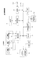
図2は、第1の実施の形態としての撮像装置1の内部構成を示すブロック図である。
図示するようにして撮像装置1は、システムコントローラ2、撮像部3、撮像制御部4、表示部5、表示制御部6、操作入力部7、傾きセンサ8、ストレージ部9、画像信号処理部10、バス11、通信部12、メモリ13、一時メモリ14を有する。
[Internal configuration example of wearable automatic imaging device]
FIG. 2 is a block diagram showing an internal configuration of the
As illustrated, the
システムコントローラ2は、例えばCPU(Central Processing Unit)、ROM(Read Only Memory)、RAM(Random Access Memory)、不揮発性メモリ部、インターフェース部を備えたマイクロコンピュータにより構成され、撮像装置1の全体を制御する制御部とされる。このシステムコントローラ2は内部のROM等に保持したプログラムに基づいて、各種演算処理やバス11を介した各部と制御信号等のやりとりを行い、各部に所要の動作を実行させる。
The
撮像部3は、撮像光学系3a、撮像素子部3b、撮像信号処理部3cを有する。
撮像部3における撮像光学系3aでは、図1に示した撮像レンズ3Lや、絞り、ズームレンズ、フォーカスレンズなどを備えて構成されるレンズ系と、レンズ系に対してフォーカス動作やズーム動作を行わせるための駆動系等が備えられる。
また撮像部3における撮像素子部3bでは、撮像光学系3aで得られる撮像光を検出し、光電変換を行うことで撮像信号を生成する固体撮像素子アレイが設けられる。固体撮像素子アレイは、例えばCCD(Charge Coupled Device)センサアレイや、CMOS(Complementary Metal Oxide Semiconductor)センサアレイとされる。
また撮像部3における撮像信号処理部3cでは、固体撮像素子によって得られる信号に対するゲイン調整や波形整形を行うサンプルホールド/AGC(Automatic Gain Control)回路や、ビデオA/Dコンバータを備え、デジタルデータとしての撮像画像データを得る。また撮像画像データに対してホワイトバランス処理、輝度処理、色信号処理などを行う。
The imaging unit 3 includes an imaging
The imaging
In the
The imaging
これらの撮像光学系3a、撮像素子部3b、撮像信号処理部3cを有する撮像部3により、撮像が行われ、撮像画像データが得られる。
この撮像部3の撮像動作によって得られた画像データは、撮像制御部4で処理される。
撮像制御部4は、システムコントローラ2の制御に従って、撮像画像データを各種の圧縮率で圧縮する画像圧縮処理や、画サイズ変換処理、画像フォーマット変換処理などの処理を行い、また動作状況に応じて、撮像画像データをバス11を介して接続される各部(表示制御部6、ストレージ部9、通信部12、一時メモリ14など)へ転送する処理を行う。
また撮像制御部4はシステムコントローラ2の指示に基づいて、撮像部3における撮像動作のオン/オフ制御、シャッタ処理、撮像光学系3aのズームレンズ、フォーカスレンズの駆動制御、撮像素子部3bの感度やフレームレートの制御、撮像信号処理部3cの各処理のパラメータ制御や実行処理の設定なども行う。
Imaging is performed by the imaging unit 3 including the imaging
Image data obtained by the imaging operation of the imaging unit 3 is processed by the imaging control unit 4.
The imaging control unit 4 performs processing such as image compression processing for compressing captured image data at various compression ratios, image size conversion processing, and image format conversion processing according to the control of the
The imaging control unit 4 controls on / off of imaging operation in the imaging unit 3, shutter processing, drive control of the zoom lens and focus lens of the imaging
撮像装置1においてユーザに対して表示を行う構成としては、表示部5、表示制御部6が設けられる。
この表示部5には、液晶ディスプレイ等の表示パネル部と、該表示パネル部を表示駆動する表示駆動部が設けられる。表示駆動部は、表示パネル部に画像表示を行わせるための画素駆動回路で構成されている。画素駆動回路は表示パネル部においてマトリクス状に配置されている各画素について、それぞれ所定の水平/垂直駆動タイミングで映像信号に基づく駆動信号を印加し、表示を実行させる。
表示制御部6は、システムコントローラ2の制御に基づいて、表示部5における画素駆動回路を駆動し所定の表示を実行させる。例えば撮像部3で撮像される画像のリアルタイムモニタ表示や、ストレージ部9に記録された撮像画像データについての再生画像の表示などが実行される。
またこれらの表示のために、例えば輝度レベル調整、色補正、コントラスト調整、シャープネス(輪郭強調)調整などを行うことができる。また画像データの一部を拡大した拡大画像の生成、或いは縮小画像の生成、ソフトフォーカス、モザイク、輝度反転、画像内の一部のハイライト表示(強調表示)、全体の色の雰囲気の変化などの画像エフェクト処理なども行うことができる。
A
The
The display control unit 6 drives a pixel driving circuit in the
For these displays, for example, brightness level adjustment, color correction, contrast adjustment, sharpness (outline emphasis) adjustment, and the like can be performed. Also, generation of an enlarged image obtained by enlarging a part of image data, generation of a reduced image, soft focus, mosaic, luminance inversion, highlight display (highlight display) of a part of the image, change in atmosphere of the whole color, etc. Image effect processing can also be performed.
操作入力部7は、例えばキー、ボタン、ダイヤル等の操作子を有するものとされ、例えば、電源オン/オフ操作や、自動撮像に関連する操作のための操作子や、所要の入力操作のための操作子が形成される。また、自動撮像だけでなく、ユーザのシャッタ操作に応じた撮像も可能とする場合は、撮像に関するユーザ操作として例えばシャッタ操作、ズームの操作、露出の設定操作、セルフタイマ操作などに用いる操作子が形成されるようにしてもよい。
操作入力部7は、このような操作子から得られる情報をシステムコントローラ2に供給し、システムコントローラ2はこれらの情報に対応した必要な演算処理や制御を行う。
The operation input unit 7 has operation elements such as keys, buttons, and dials. For example, an operation element for power on / off operation, an operation related to automatic imaging, and a required input operation. Are formed. When not only automatic imaging but also imaging according to a user's shutter operation is possible, for example, an operator used for user operation related to imaging is a shutter operation, a zoom operation, an exposure setting operation, a self-timer operation, or the like. It may be formed.
The operation input unit 7 supplies information obtained from such an operator to the
ストレージ部9は、撮像画像データを始めとした各種データの保存に用いられる。
このストレージ部9は、フラッシュメモリなどの固体メモリにより構成されても良いし、例えばHDD(Hard Disk Drive)により構成されてもよい。
また内蔵の記録媒体ではなく、可搬性を有する記録媒体、例えば固体メモリを内蔵したメモリカード、CD(Compact Disc)やDVD(Digital Versatile Disc)などの光ディスク、光磁気ディスク、ホログラムメモリなどの記録媒体に対応する記録再生ドライブなどとされても良い。
もちろん、固体メモリやHDD等の内蔵タイプのメモリと、可搬性記録媒体に対する記録再生ドライブの両方が搭載されてもよい。
このストレージ部9は、システムコントローラ2の制御に基づいて、撮像画像データその他の各種データの記録/再生を行う。
The storage unit 9 is used to store various data including captured image data.
The storage unit 9 may be configured by a solid-state memory such as a flash memory, or may be configured by an HDD (Hard Disk Drive), for example.
Also, not a built-in recording medium, but a portable recording medium, for example, a memory card incorporating a solid-state memory, an optical disk such as a CD (Compact Disc) or a DVD (Digital Versatile Disc), a magneto-optical disk, a hologram memory, or the like. May be a recording / reproducing drive corresponding to the above.
Of course, both a built-in type memory such as a solid-state memory and an HDD, and a recording / reproducing drive for a portable recording medium may be mounted.
The storage unit 9 records / reproduces captured image data and other various data based on the control of the
通信部12は、各種の外部機器とデータ通信を行う部位として設けられる。
例えば、図示しないサーバ装置との間でのデータの送受信を行うようにしてもよい。その場合、例えば無線LAN、やブルートゥースなどの方式で、ネットワークアクセスポイントに対する近距離無線通信を介してネットワーク通信を行う構成としてもよいし、対応する通信機能を備えたサーバ装置との間で直接無線通信を行うものでもよい。
また、通信部12は、例えばUSB(Universal Serial Bus)方式等のインターフェイスを用いてパーソナルコンピュータなどの機器と接続し、データの送受信を行うようにしてもよい。
この通信部12により、例えば撮像してストレージ部9に格納した撮像画像データを、パーソナルコンピュータその他の外部機器に転送することができる。
The
For example, data transmission / reception with a server device (not shown) may be performed. In that case, for example, a configuration in which network communication is performed via short-range wireless communication with a network access point by a method such as wireless LAN or Bluetooth, or direct wireless communication with a server device having a corresponding communication function is possible. Communication may be performed.
Further, the
The
ここでは一例として、上記通信部12としては、例えばUSB(Universal Serial Bus)方式等の有線接続のインターフェイスを用いて外部機器とのデータ通信を行うことが可能に構成されているとする。図中インタフェース端子TI/Fは、このような有線接続によるデータ通信を行うにあって外部機器側と接続するための通信ケーブルが接続される端子となる。
Here, as an example, it is assumed that the
一時メモリ14は、各種データの一時保持のために設けられ、例えばRAMや不揮発性メモリなど、データ書き換えが可能なメモリ装置で構成される。特に本例の場合、当該一時メモリ14に対しては後述する画像信号処理部10による画像処理対象となる撮像画像データが一時保持され、画像信号処理部10による画像信号処理の作業領域としても利用される。
The
傾きセンサ8、画像信号処理部10は、実施の形態としての画像傾き補正処理を行うための構成として設けられる。
傾きセンサ8は、重力センサを備え、撮像装置1に作用する重力の方向を表す検出信号をシステムコントローラ2に出力する。システムコントローラ2は、上記検出信号に基づき撮像装置1の傾き量を検出(算出)する。
The tilt sensor 8 and the image
The tilt sensor 8 includes a gravity sensor, and outputs a detection signal indicating the direction of gravity acting on the
画像信号処理部10は、例えばDSP(Digital Signal Processor)で構成され、システムコントローラ2の制御に基づいて撮像画像データについて各種の画像信号処理を実行する。特に本例の場合は、後述する実施の形態としての傾き補正処理に係る動作を行うようにされる。
画像信号処理部10にはメモリ13が備えられ、当該メモリ13には画像信号処理部10が画像信号処理を実行する上で必要な各種のパラメータ(例えばフィルタ係数等)などが格納される。また、特に本実施の形態の場合は、画像信号処理部10に後述する実施の形態としての傾き補正処理に係る動作を行わせるための補正処理プログラム13aが格納される。すなわち、DSPとしての画像信号処理部10は、メモリ13内から読み出した当該補正処理プログラム13aに基づきハードウェアリソースを用いたデジタル信号処理を行うことで、後述する実施の形態としての処理動作を行うようにされている。
The image
The image
なお、実施の形態の撮像装置1の構成としてはこの図2で説明した構成に限定されるものでなく、実際に実施される動作例や機能に応じて各種の構成要素の追加・削除は当然考えられるものである。
Note that the configuration of the
[画像傾き補正処理]
図2に示した撮像装置1では、自動撮像機能として、撮像部3で得られる撮像画像に基づく撮像画像データを自動的に取り込む動作を行う。具体的には、システムコントローラ2が撮像制御部4に対する指示を行って、例えば一定時間おきに撮像画像データの取り込みを行う。
[Image tilt correction processing]
In the
ここで、これまでの説明から理解されるように、本実施の形態の撮像装置1としては、使用者に装着された状態で被写体を自動撮像する、装着型自動撮像装置とされる。このような装着型自動撮像装置としては、先に説明したライフログカメラとして、ユーザが自身の行動履歴や思い出を画像データとして保存する用途に使用されることが想定される。
Here, as can be understood from the above description, the
しかしながら、このようなライフログカメラとして使用することを想定した場合、先に説明したようにユーザ(つまり装着者)の使用に伴い自動撮像された画像データに大きな傾きの変動が生じる可能性が高く、撮像画像を送り再生(表示)した場合には、再生画像が不自然に揺れてしまうことが問題となる。特に、ライフログカメラによる撮像画像については、前述のように比較的高速な送り再生が行われることが想定されるので、このような再生画像の揺れがユーザに対して非常に大きな不快感を与えてしまう可能性が高い。 However, when it is assumed to be used as such a life log camera, as described above, there is a high possibility that a large change in inclination occurs in the image data automatically picked up as the user (that is, the wearer) uses. When a captured image is sent and reproduced (displayed), the reproduced image is unnaturally shaken. In particular, for images captured by a lifelog camera, it is assumed that relatively high-speed feed playback is performed as described above. Therefore, such a shake of the playback image gives a very unpleasant feeling to the user. There is a high possibility that
そこで、本実施の形態では、図2に示した画像信号処理10により、自動撮像された画像データについてその傾きの補正を行うものとしている。具体的な補正内容として、第1の実施の形態では、画像データの傾き量がゼロとなるように補正を行うものである。
Therefore, in the present embodiment, the inclination of the automatically captured image data is corrected by the
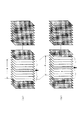
図3は、本実施の形態としての画像傾き補正処理について説明するための図である。
先ず、図3(a)では、撮像画像データの一例として、傾きセンサ8の出力に基づき傾き量agl=−10が検出された場合の撮像画像データの内容を例示している。ここで、傾き量agl=0は、水平方向(重力が作用する方向に対して直交する方向)を指すものであるとする。
このように傾き量agl=−10が検出された画像としては、例えば図3(a)に示されている画像内の地面が水平方向と平行であるとすれば、画像データの水平ライン方向(走査方向)と画像内の地面とのなす角度が、検出された傾き量agl=−10に相当するものとなる。
FIG. 3 is a diagram for explaining the image tilt correction processing according to the present embodiment.
First, FIG. 3A illustrates the content of captured image data when an inclination amount agl = −10 is detected based on the output of the inclination sensor 8 as an example of captured image data. Here, the inclination amount agl = 0 indicates the horizontal direction (direction orthogonal to the direction in which gravity acts).
As an image in which the inclination amount agl = −10 is detected in this way, for example, if the ground in the image shown in FIG. 3A is parallel to the horizontal direction, the horizontal line direction ( The angle formed between the scanning direction) and the ground in the image corresponds to the detected inclination amount agl = −10.
このような画像の傾きをキャンセルしてゼロとするにあたり、第1の実施の形態では、次の図3(b)に示されるように、撮像画像データの一部を、水平ライン方向に対し検出された傾き量aglだけ傾けた角度で切り出す(トリミングする)ものとしている。つまりこの場合は、水平ライン方向に対し傾き量agl=−10だけ傾けた角度で切り出すようにされる。
このとき、傾き補正を行う上で目標とする目標傾き量を「T-agl」とおく。この場合、画像の傾き量はゼロとすることを目標とするので、目標傾き量T-aglは図示もされているようにT-agl=0である。
In canceling such image tilt to zero, in the first embodiment, as shown in FIG. 3B, a part of the captured image data is detected in the horizontal line direction. It is assumed that it is cut out (trimmed) at an angle inclined by the amount of inclination agl. That is, in this case, the image is cut out at an angle inclined by the inclination amount agl = −10 with respect to the horizontal line direction.
At this time, a target tilt amount that is a target for tilt correction is set to “T-agl”. In this case, since the target is to set the tilt amount of the image to zero, the target tilt amount T-agl is T-agl = 0 as shown.
図3(c)は、図3(b)に示した傾き補正が行われた結果得られる補正後画像を例示している。図示するように補正後画像では、画像内の地面と水平ライン方向とが平行とされ、これによって傾き量aglがゼロとなるように補正が行われたことが示されている。 FIG. 3C illustrates a corrected image obtained as a result of the tilt correction shown in FIG. As shown in the figure, the corrected image shows that the ground in the image is parallel to the horizontal line direction, and the correction is performed so that the inclination amount agl becomes zero.
第1の実施の形態の場合、このような画像信号処理部10による傾き補正処理の施された撮像画像データは、システムコントローラ2による制御に基づきストレージ部9に記録される。
この結果、ストレージ部9に対しては、傾き補正の施された撮像画像データを保存することができ、再生時において、撮像画像データが比較的高速に送り再生されたとしても、再生画像の揺れの発生を効果的に防止することができる。このように再生画像の揺れの防止が図られることで、従来のようにユーザに不快感を与えてしまうといった事態の発生を効果的に防止することができる。
In the case of the first embodiment, the captured image data that has been subjected to the tilt correction process by the image
As a result, captured image data subjected to tilt correction can be stored in the storage unit 9, and even when captured image data is sent and reproduced at a relatively high speed during reproduction, the reproduced image is shaken. Can be effectively prevented. By preventing the playback image from shaking in this way, it is possible to effectively prevent the occurrence of a situation in which the user is uncomfortable as in the prior art.
[処理動作]
続いては、上記により説明した第1の実施の形態の撮像装置1としての動作を実現するために実行されるべき処理動作について説明する。
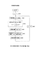
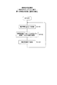
先ず、図4のフローチャートは、システムコントローラ2により実行されるべき処理動作を示している。なお、この図に示す処理動作を始めとして、以降で説明する各実施の形態にてシステムコントローラ2が実行する処理動作は、システムコントローラ2が備えるROM等の記憶手段に記憶されるプログラムに基づいて実行されるものとなる。
[Processing behavior]
Subsequently, a processing operation to be executed to realize the operation as the
First, the flowchart of FIG. 4 shows processing operations to be executed by the
図4において、この場合のシステムコントローラ2によっては、主に撮像画像データの取込制御処理と、画像取込を行ったときの傾き量の情報の取得・画像信号処理部10への転送処理と、補正処理後の撮像画像データのストレージ部9への記録制御処理とを実行するものとされている。
具体的に、先ずステップS101では、撮像タイミングを待機する処理を行う。ここで撮像タイミングとは、撮像部3により得られる撮像画像データの取り込みを行うべきとして予め定められたタイミングであり、この場合は自動撮像機能の実現のため、一定時間おきのタイミングが設定されている。
In FIG. 4, depending on the
Specifically, first, in step S101, processing for waiting for imaging timing is performed. Here, the imaging timing is a timing determined in advance so that captured image data obtained by the imaging unit 3 should be taken. In this case, a timing at regular intervals is set to realize an automatic imaging function. Yes.
そして、撮像タイミングに至ったとした場合は、ステップS102において、撮像画像データの取込制御処理を実行する。すなわち、撮像制御部4に対する制御を行って、撮像部3にて得られている撮像画像データの、一時メモリ14への取り込みを実行させる。
If it is determined that the imaging timing has been reached, in step S102, captured image data capture control processing is executed. That is, the imaging control unit 4 is controlled to cause the captured image data obtained by the imaging unit 3 to be taken into the
続くステップS103では、現在の傾き情報の取得処理として、傾きセンサ8の検出信号に基づく計算処理を行うことで、傾き量aglの情報(傾き情報agl)を取得する。
さらに、続くステップS104において、傾き情報(傾き量agl)を画像信号処理部10に転送した上で、次のステップS105では、画像信号処理部10からの補正処理終了通知(後述する)を待機する。
画像信号処理部10からの補正終了通知があった場合は、ステップS106において、補正処理された画像データをストレージ部9に記録するための処理を行う。この場合、画像信号処理部10による補正処理は、一時メモリ14を作業領域として行われ、補正処理後の撮像画像データは一時メモリ14に格納されることになる。従って当該ステップS106では、このように一時メモリ14にて格納される補正処理後の撮像画像データをストレージ部9に転送してこれを記録させるための制御処理を行う。
ステップS106による記録制御処理を実行すると、図示するようにしてステップS101に戻るようにされる。
In subsequent step S103, as current inclination information acquisition processing, calculation processing based on the detection signal of the inclination sensor 8 is performed to acquire information on the inclination amount agl (inclination information agl).
Further, in the subsequent step S104, the tilt information (tilt amount agl) is transferred to the image
When the correction end notification is received from the image
When the recording control process in step S106 is executed, the process returns to step S101 as shown in the figure.
なお、図示による説明は省略したが、この図4に示す処理動作としては、例えば撮像装置1の電源をオフとする操作入力や撮像動作の停止を指示する操作入力など、予め自動撮像動作を停止すべきとして設定された停止トリガの発生に応じて終了するものとなる。具体的にシステムコントローラ2は、この図に示される処理動作として並行して上記停止トリガの発生を待機する処理動作を行っており、当該停止トリガの発生に応じて図4に示す処理動作を終了するようにされている。
なお、この点については、以後の各実施の形態で説明するシステムコントローラ2の処理動作について全て共通であるとする。
Although the description by illustration is omitted, as the processing operation shown in FIG. 4, the automatic imaging operation is stopped in advance, for example, an operation input for turning off the power of the
In this regard, it is assumed that all processing operations of the
図5は、上記のようにしてシステムコントローラ2により行われる一時メモリ14への撮像画像データの取込、及び傾き量aglの転送に対応して行われるべき、画像信号処理部10による処理動作をフローチャート化して示している。
なお、先の説明からも理解されるように、この図に示される処理動作は、図1に示すメモリ13内に格納される補正処理プログラム13aに基づき画像信号処理部10がハードウェアリソースを用いたデジタル信号処理を行うことで実現されるものである。
FIG. 5 shows processing operations performed by the image
As can be understood from the above description, the processing operation shown in this figure uses hardware resources by the image
先ず、ステップS201では、傾き情報aglの取得処理を行う。すなわち、先のステップS104(図4)によりシステムコントローラ2から転送される傾き量aglの情報を取得する処理を行う。
続くステップS202では、目標傾き量T-agl=agl−agl=0となるように画像の傾きを補正する処理を行う。すなわち、先のステップS102(図4)の処理によって一時メモリ14に取り込まれた撮像画像データについて、上記ステップS201で取得した傾き量aglの情報に基づき、先の図3(b)に示したようにして上記撮像画像データの一部を水平ライン方向に対し上記傾き量aglだけ傾けた角度で切り出す処理を実行する。
First, in step S201, an inclination information agl acquisition process is performed. That is, the process of acquiring information on the tilt amount agl transferred from the
In the subsequent step S202, processing for correcting the inclination of the image is performed so that the target inclination amount T-agl = agl-agl = 0. That is, as shown in FIG. 3B, the captured image data captured in the
次のステップS203では、補正処理終了通知をシステムコントローラ2に対して行う。ステップS203の処理を実行すると、ステップS201に戻るようにされる。
In the next step S203, a correction processing end notification is sent to the
なお、この図に示される画像信号処理部10による処理動作は、システムコントローラ2より上述した停止トリガの発生が検出された場合に終了するものとなる。つまり、図示による説明は省略したが、システムコントローラ2は、上記停止トリガの発生に応じ画像信号処理部10に対し処理終了通知を行うようにされ、画像信号処理部10は、当該処理終了通知に応じ、この図に示す処理動作を終了するようにされている。
なお、この点については、以降の各実施の形態の画像信号処理部10による処理動作について全て共通であるとする。
Note that the processing operation by the image
In this regard, it is assumed that the processing operations by the image
<第2の実施の形態>
続いては、第2の実施の形態について説明する。第2の実施の形態は、傾き量をゼロとするのではなく、最初に撮像された画像の傾き量に合わせて補正するようにしたものである。
なお、第2の実施の形態において、撮像装置1の構成については先の図1、図2に示したものとほぼ同様となるので改めての図示による説明は省略する。この場合、傾き補正の処理内容として画像信号処理部10が実行する処理内容のみが異なるものとなるので、以下では、この場合の画像信号処理部10により実行される処理動作のみについて説明を行う。
この場合も、システムコントローラ2により実行されるべき処理動作は、先の図4に示したものと同様となる。すなわち、この場合のシステムコントローラ2によっても、主に撮像画像データの取込制御処理、画像取込を行ったときの傾き量の情報の取得・画像信号処理部10への転送処理、補正処理後の撮像画像データのストレージ部9への記録制御処理が実行されるように為されていればよい。
<Second Embodiment>
Subsequently, a second embodiment will be described. In the second embodiment, the amount of tilt is not set to zero, but correction is made in accordance with the amount of tilt of the first captured image.
In the second embodiment, the configuration of the
Also in this case, the processing operation to be executed by the
図6は、第2の実施の形態の撮像装置1における画像信号処理部10により実行される処理動作をフローチャート化して示した図である。
なお、第2の実施の形態の場合、画像信号処理部10によってこの図に示される処理動作が実行されるようにして、メモリ13内に格納される補正処理プログラム13aの内容が第1の実施の形態の場合から変更されるものとなる。このようにDSPとしての画像信号処理部10に実行されるべき処理動作の内容を異ならせるために補正処理プログラム13aを変更させる点については、以降で説明する各実施の形態の場合も同様であることは言うまでもない。
FIG. 6 is a flowchart illustrating the processing operation executed by the image
In the case of the second embodiment, the processing operation shown in this figure is executed by the image
図6において、この場合もシステムコントローラ2から転送される傾き量aglの情報を取得する処理(ステップS301)は共通となる。
この場合は、ステップS301により傾き量aglの情報を取得した後、ステップS302において、最初の画像であるか否かを判別するようにされる。ここで、この場合における「最初の画像」とは、一連の自動撮像動作(例えば電源オンや自動撮像開始指示などに応じて開始される一連の自動撮像動作)において最初に取り込みの行われた撮像画像データを指すものであるとする。
In FIG. 6, the process (step S301) for acquiring the information about the inclination amount agl transferred from the
In this case, after the information of the inclination amount agl is acquired in step S301, it is determined whether or not it is the first image in step S302. Here, the “first image” in this case refers to an image captured first in a series of automatic imaging operations (for example, a series of automatic imaging operations started in response to a power-on or automatic imaging start instruction). It is assumed that it points to image data.
上記ステップS302において、最初の画像であるとして肯定結果が得られた場合は、ステップS303に進み目標傾き量T-aglを取得した傾き量aglに設定し、ステップS304に進むようにされる。
一方、最初の画像ではないとして否定結果が得られた場合は、そのままステップS304に進むようにされる。
If an affirmative result is obtained in step S302 that the image is the first image, the process proceeds to step S303, the target tilt amount T-agl is set to the acquired tilt amount agl, and the process proceeds to step S304.
On the other hand, if a negative result is obtained because it is not the first image, the process proceeds to step S304 as it is.
ステップS304では、傾き量がT-aglとなるように画像の傾きを補正する処理を行う。第1の実施の形態では、目標傾き量T-agl=0となるようにするために、画像データの水平ライン方向に対し、検出された傾き量aglだけ傾けた角度でトリミングを行うものとしたが、この場合は、画像の傾きを目標傾き量T-aglとするために、画像データの水平ライン方向に対し、「agl−T-agl」だけ傾けた角度でトリミングを行う。例えば、目標傾き量T-agl=−10であり、検出された傾き量agl=+10であれば、「10−(−10)=20」より、水平ライン方向に対しagl=20に相当する角度だけ傾けた角度でトリミングを行う。 In step S304, processing for correcting the tilt of the image is performed so that the tilt amount becomes T-agl. In the first embodiment, trimming is performed at an angle inclined by the detected inclination amount agl with respect to the horizontal line direction of the image data so that the target inclination amount T-agl = 0. However, in this case, in order to set the inclination of the image to the target inclination amount T-agl, trimming is performed at an angle inclined by “agl−T-agl” with respect to the horizontal line direction of the image data. For example, if the target inclination amount T-agl = −10 and the detected inclination amount agl = + 10, an angle corresponding to agl = 20 with respect to the horizontal line direction from “10 − (− 10) = 20”. Trimming at a tilted angle.
傾き補正処理が完了すると、この場合もシステムコントローラ2に対し補正処理終了通知を行い(S305)、その後ステップS301に戻るようにされる。
When the inclination correction process is completed, a correction process end notification is sent to the
このようにして、撮像画像データの傾きを最初の画像の傾き量に合わせて補正することによっても、再生画像の揺れの発生防止を図ることができ、この結果、画像送り再生時にユーザへの不快感を与えないようにすることができる。
In this way, by correcting the inclination of the captured image data in accordance with the inclination amount of the first image, it is possible to prevent the reproduction image from being shaken. It is possible to avoid giving pleasure.
<第3の実施の形態>
第3の実施の形態は、撮像画像データの傾きを、平均の傾き量に合わせて補正するものである。
なお、第3の実施の形態としても、撮像装置1の構成については先の図1、図2に示したものとほぼ同様となるので改めての図示による説明は省略し、この場合も傾き補正の処理内容として画像信号処理部10が実行する処理内容のみが異なるものとなることから、以下では、この場合の画像信号処理部10により実行される処理動作のみについて説明を行う。この場合もシステムコントローラ2による処理動作は先の図4に示したものと同様である。
<Third Embodiment>
In the third embodiment, the inclination of captured image data is corrected in accordance with the average inclination amount.
In the third embodiment, the configuration of the
図7は、第3の実施の形態の撮像装置1における画像信号処理部10により実行される処理動作をフローチャート化して示した図である。
図7において、この場合の画像信号処理部10では、一連の自動撮像動作の開始に応じ、先ずはステップS401において、変数n=1にセットする。この変数nは、撮像画像データの識別のために、この場合の画像信号処理部10にてカウントされる値となる。
そして、このように変数n=1にセットすると、この場合もシステムコントローラ2から転送される傾き量agl(この場合はnをカウントすることに伴い傾き量agl(n)とする)を取得(S402)する。
FIG. 7 is a flowchart illustrating the processing operation executed by the image
In FIG. 7, the image
When the variable n is set to 1 in this way, the inclination amount agl transferred from the system controller 2 (in this case, the inclination amount agl (n) is included as n is counted) is acquired (S402). )
続くステップS403では、図示される計算を行うことで、傾き量の平均値aveを算出する。ここで、図中の式において、「N」は一連の自動撮像動作の開始から現在までに傾き量aglが取得された回数(すなわち画像撮像回数)を表す。つまりこの場合は、一連の自動撮像動作の開始から現在までに取得された全撮像画像データについての傾き量aglの平均値を計算するようにされているものである。 In the subsequent step S403, the average value ave of the tilt amount is calculated by performing the calculation shown in the figure. Here, in the equation in the figure, “N” represents the number of times that the inclination amount agl has been acquired from the start of a series of automatic imaging operations to the present (that is, the number of image imaging). That is, in this case, the average value of the inclination amount agl for all the captured image data acquired from the start of a series of automatic imaging operations to the present is calculated.
次のステップS404では、目標傾き量T-agl=aveに設定する。さらに、次のステップS405では、傾き量がT-aglとなるように画像データ(n)の傾きを補正する。すなわち、今回取り込みの行われた画像データ(n)について、水平ライン方向に対し「agl(n)−T-agl」だけ傾けた角度でトリミングを行う。 In the next step S404, the target inclination amount T-agl = ave is set. Further, in the next step S405, the inclination of the image data (n) is corrected so that the inclination amount becomes T-agl. That is, the image data (n) captured this time is trimmed at an angle inclined by “agl (n) −T-agl” with respect to the horizontal line direction.
ステップS405による傾き補正処理が完了すると、次のステップS406にてシステムコントローラ2に対する補正処理終了通知を行う。その上で、この場合はステップS407にて変数nの値をインクリメント(n=n+1)した後、ステップS402に戻るようにされる。
When the tilt correction process in step S405 is completed, a correction process end notification is sent to the
このようにして、撮像画像データの傾きを平均の傾き量に合わせて補正することによっても、再生画像の揺れの発生防止を図ることができ、画像送り再生時にユーザへの不快感を与えないようにすることができる。 By correcting the inclination of the captured image data in accordance with the average inclination amount in this way, it is possible to prevent the reproduction image from being shaken, and to prevent the user from feeling uncomfortable at the time of image feed reproduction. Can be.
ここで、先の図7のステップS403に示した平均値算出のための式によると、この場合の平均値算出では、平均値の算出範囲(平均値の算出対象とする画像データ枚数)が撮像画像データの取り込み回数に比例して大きくなっていくものとなる。すなわち、撮像画像データの取り込み回数が「N」のときは、N枚の撮像画像データについての平均値を求めるということになり、結果、取り込み回数が増えるごとに平均値算出のための処理負担が増大化する傾向となってしまう。 Here, according to the average value calculation formula shown in step S403 in FIG. 7, in the average value calculation in this case, the average value calculation range (the number of image data for which the average value is calculated) is captured. It becomes larger in proportion to the number of times image data is captured. That is, when the number of captured image data captures is “N”, an average value for N captured image data is obtained. As a result, the processing load for calculating the average value increases as the number of captures increases. It tends to increase.
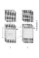
そこで、第3の実施の形態としては、次の図8に示されるようにして、平均値の算出範囲(画像データ枚数)を「a」で固定とし、平均値の算出範囲を画像取り込み回数ごとにシフトさせていくという手法を採ることもできる。
この図8では、斜線を施した撮像画像データが現在の取り込み撮像画像データ(最新の取り込み撮像画像データ)を表しており、図8(b)は、図8(a)の場合からさらに次の撮像画像データの取り込みが行われた場合を示している。これら図8(a)(b)の比較から明らかなように、平均値の算出範囲を「a」で固定とするにあたっては、現在の撮像画像データを画像データ(n)としたとき、当該画像データ(n)から画像データ(n−a)までの範囲を対象として平均値算出を行うものとなる。
Therefore, as a third embodiment, as shown in FIG. 8, the average value calculation range (number of image data) is fixed at “a”, and the average value calculation range is set for each number of times of image capture. It is also possible to adopt a method of shifting to.
In FIG. 8, the captured image data with hatching represents the current captured captured image data (latest captured captured image data), and FIG. 8B further illustrates the following from the case of FIG. A case where captured image data is captured is shown. As is clear from the comparison between FIGS. 8A and 8B, when the average value calculation range is fixed to “a”, when the current captured image data is the image data (n), the image The average value is calculated for the range from data (n) to image data (na).
図9は、図8に示した第3の実施の形態の変形例としての傾き補正処理を実現するために画像信号処理部10にて実行されるべき処理動作を示している。なお、この図において、先の図7にて説明した処理と同様となる処理については同一のステップ番号を付して説明を省略する。
図示するようにして、ステップS401〜S406までの処理動作は、先の図7に示したものと同様となる。その上でこの場合は、ステップS406における補正処理終了通知を行った後、ステップS501において、先ずはn>aであるか否かを判別する。n>aでないとして否定結果が得られた場合は、図示するようにしてステップS407に進んでn=n+1とした後、ステップS402に戻るようにされる。
一方、ステップS501においてn>aであるとして肯定結果が得られた場合は、ステップS502に進んで平均値の算出範囲を「n−a」〜「n」に変更する処理を行う。すなわち、ステップS403に示す式に照らして言えば、i=1からi=n−aに変更することに相当する。このステップS502の処理を実行すると、ステップS407に進む。
FIG. 9 shows processing operations to be executed by the image
As shown in the figure, the processing operations from step S401 to S406 are the same as those shown in FIG. In this case, after the completion of the correction process in step S406, first, in step S501, it is determined whether or not n> a. If a negative result is obtained because it is not n> a, the process proceeds to step S407 as shown in the figure, and after n = n + 1, the process returns to step S402.
On the other hand, if an affirmative result is obtained in step S501 that n> a, the process proceeds to step S502 to perform processing for changing the average value calculation range from “na” to “n”. That is, in the light of the equation shown in step S403, this corresponds to changing from i = 1 to i = na. When the process of step S502 is executed, the process proceeds to step S407.
このような処理が実行されることで、撮像画像データの取り込み回数(n)が平均値算出範囲の値「a」以下の場合には先の図7と同様の平均値算出が行われた上で、平均値算出範囲の値「a」よりも大きくなった以降においては、算出範囲aをシフトさせるようにして平均値の算出処理を行うことができる。
これにより、撮像画像データの取り込み回数の増加に伴い処理負担が増大化する傾向となってしまうことを防止することができる。
By executing such processing, the average value calculation similar to that of FIG. 7 is performed when the number (n) of captured image data captures is equal to or less than the value “a” of the average value calculation range. Thus, after the average value calculation range becomes larger than the value “a”, the calculation process of the average value can be performed by shifting the calculation range a.
As a result, it is possible to prevent the processing load from increasing as the number of captured image data captures increases.
<第4の実施の形態>
第4の実施の形態は、傾き補正量が所定値より大となる撮像画像データについては、再生対象から除外されるようにするものである。具体的には、傾き補正量が所定値以上となる撮像画像データについては補正処理を施さず、且つストレージ部9への記録対象から除外することで、当該撮像画像データが再生対象とはならないように図るものである。
なお、第4の実施の形態としても、傾き補正の処理内容として画像信号処理部10が実行する処理内容のみが異なるものとなることから、撮像装置1の構成については改めての図示による説明は省略し、画像信号処理部10により実行される処理動作のみについて説明を行う。
<Fourth embodiment>
In the fourth embodiment, captured image data whose inclination correction amount is greater than a predetermined value is excluded from the reproduction target. Specifically, the captured image data whose inclination correction amount is equal to or greater than a predetermined value is not subjected to the correction process, and is excluded from the recording target in the storage unit 9 so that the captured image data does not become the playback target. It is intended.
In the fourth embodiment as well, only the processing content executed by the image
図10は、第4の実施の形態の画像信号処理部10により実現される動作を模式的に示している。
ここで、第4の実施の形態の補正処理としては、先の第1〜第3の実施の形態の補正処理と組み合わせることができる。つまり、第4の実施の形態において、図中の目標補正量T-aglとしては、T-agl=0、または「最初に撮像された画像データの傾き量agl」、または「平均値ave」とすることができるものである。
FIG. 10 schematically shows an operation realized by the image
Here, the correction processing of the fourth embodiment can be combined with the correction processing of the first to third embodiments. That is, in the fourth embodiment, as the target correction amount T-agl in the figure, T-agl = 0, “the amount of inclination agl of the first captured image data”, or “average value ave” Is something that can be done.
図10において、この場合の補正処理では、撮像画像データの取り込みが行われるごとに、その撮像画像データについて、傾き補正量が所定の閾値th1より大であるか否かを判別する。具体的には、上記撮像画像データについて検出された傾き量aglと目標傾き量T-aglとの差(|T-agl−agl|)が、上記閾値th1より大であるか否かを判別する。
そして、この判別の結果、目標傾き量T-aglとの差(すなわち傾き補正量)が上記閾値th1より大であるとされた場合は、その撮像画像データについては再生対象から除外されるべきとして、補正処理は実行しないようにする。具体的には、その撮像画像データについての補正処理は実行せず、さらにシステムコントローラ2に対し、当該撮像画像データをストレージ部9への記録対象から除外するための対象外通知を行う。
また、傾き補正量が上記閾値th1より大ではない(つまり閾値th1以下である)とされた場合は、その撮像画像データについては再生対象とされるべきとして、補正処理を実行する。つまり、撮像画像データの傾きが目標傾き量T-aglとなるようにして補正処理を実行すると共に、システムコントローラ2に対する補正処理終了通知を行って、ストレージ部9への記録を実行させる。
In FIG. 10, in the correction processing in this case, each time captured image data is captured, it is determined whether or not the tilt correction amount is larger than a predetermined threshold th1 for the captured image data. Specifically, it is determined whether or not the difference (| T-agl-agl |) between the tilt amount agl detected for the captured image data and the target tilt amount T-agl is larger than the threshold th1. .
As a result of this determination, if the difference from the target tilt amount T-agl (that is, the tilt correction amount) is greater than the threshold th1, the captured image data should be excluded from the reproduction target. The correction process is not executed. Specifically, the correction processing for the captured image data is not executed, and further, the
If the inclination correction amount is not larger than the threshold th1 (that is, not more than the threshold th1), correction processing is executed assuming that the captured image data is to be reproduced. That is, the correction processing is executed so that the inclination of the captured image data becomes the target inclination amount T-agl, and the correction processing end notification is sent to the
このような第4の実施の形態としての動作により、傾き補正量が非常に大きな撮像画像データについては傾き補正処理及び再生の対象から除外されるようにすることができる。
ここで、本例の場合、傾き補正処理としては、トリミングによる補正を行うものとしているが、このようにトリミングを行う場合は、傾き補正量が大きくなるに従って、補正後の画像サイズが縮小化する傾向となることが懸念される。そこで、上記のようにして傾き量の大きいものについては補正処理の対象外とすることで、極端に小さな画像に補正されてしまうといった事態を防止することができる。
このとき、例えば補正後の画像サイズを統一することを前提とするのであれば、補正時のトリミングサイズを、傾き補正量が上記閾値th1のときにトリミング画像のサイズを最大とすることのできるサイズに設定しておくことで、補正画像の全てについて画像サイズの統一を図ることができる。
また、仮に、トリミング以外の他の手法により傾き補正を行うとした場合においても、画像の回転量は所定以下に抑えることができる等、傾き補正に要する処理負担が必要以上に増大化しないようにできるという効果を得ることができる。
By such an operation as the fourth embodiment, captured image data having a very large tilt correction amount can be excluded from targets for tilt correction processing and reproduction.
Here, in the present example, correction by trimming is performed as the tilt correction process. However, when trimming is performed in this way, the corrected image size is reduced as the tilt correction amount increases. There is concern about the trend. In view of this, it is possible to prevent a case where an image having a large tilt amount is excluded from correction processing as described above, so that an extremely small image is corrected.
At this time, for example, if it is assumed that the image size after correction is unified, the trimming size at the time of correction is the size that can maximize the size of the trimmed image when the inclination correction amount is the threshold value th1. By setting to, it is possible to unify the image size for all of the corrected images.
Also, even if the tilt correction is performed by a method other than trimming, the processing amount required for the tilt correction is not increased more than necessary, for example, the image rotation amount can be suppressed to a predetermined value or less. The effect that it is possible can be obtained.
なお、確認のために述べておくと、上記動作によれば、傾き補正量が閾値th1より大となる画像データについては、再生(記録)の対象からも除外されるようになっているので、これまでの各実施の形態の場合と同様に、再生画像の揺れの発生を防止できるという効果は変わらずに得ることができるものとなる。 For confirmation, according to the above operation, the image data with the inclination correction amount larger than the threshold value th1 is excluded from the reproduction (recording) target. As in the case of each of the previous embodiments, the effect of preventing the occurrence of the shake of the reproduced image can be obtained without change.
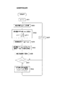
図11は、上記により説明した第4の実施の形態としての動作を実現するためにシステムコントローラ2により実行されるべき処理動作を示している。
この場合のシステムコントローラ2の処理動作として、ステップS101〜S105までの処理動作については、先の図4にて説明したものと同様となる。
この場合、ステップS105にて補正処理終了通知が無いとして否定結果が得られた場合に実行されるべき処理として、ステップS601を設ける。このステップS601では、画像信号処理部10からの対象外通知があったか否かを判別するようにされる。ステップS601において、対象外通知が無いとして否定結果が得られた場合は、ステップS105に戻るようにされる。つまりこれにより、画像信号処理部10からの補正処理終了通知か対象外通知の何れかを待機するようにされている。
FIG. 11 shows processing operations to be executed by the
As processing operations of the
In this case, step S601 is provided as a process to be executed when a negative result is obtained that there is no correction process end notification in step S105. In step S601, it is determined whether or not there is a non-target notification from the image
そして、ステップS105において、画像信号処理部10からの補正処理終了通知があったとして肯定結果が得られた場合は、ステップS106に進み、補正処理された画像データをストレージ部9に記録するための処理を実行した後、ステップS101に戻るようにされる。
また、上記ステップS601において、画像信号処理部10からの対象外通知があったとして肯定結果が得られた場合はステップS101に戻るようにされ、これによって対象外とされた撮像画像データについての記録は実行されないものとなる。
If an affirmative result is obtained in step S105 that there is a correction processing end notification from the image
In step S601, if an affirmative result is obtained because there is an out-of-target notification from the image
図12は、上記により説明した第4の実施の形態としての動作を実現するために画像信号処理部10ににより実行されるべき処理動作をフローチャート化して示している。
なお、この図12では一例として、最初の画像に傾きを合わせる第2の実施の形態の補正処理を行う場合に、第4の実施の形態を適用した場合の処理動作を例示している。
FIG. 12 is a flowchart showing the processing operation to be executed by the image
In FIG. 12, as an example, the processing operation in the case where the fourth embodiment is applied when performing the correction processing of the second embodiment in which the inclination is adjusted to the first image is illustrated.
この図12に示されるようにして、ステップS301〜S303までの処理は、先の図6に示した処理と同様となる。そして、この場合は、ステップS302にて否定結果が得られた場合、及びステップS303に続く処理として、図中ステップS701により「|T-agl−agl|>th1」であるか否かを判別する処理を行う。
ステップS701において、「|T-agl−agl|>th1」ではなく、傾き補正量が閾値th1より大ではないとして否定結果が得られた場合は、ステップS304に進み、傾き量がT-aglとなるように画像を補正する処理を行った後、ステップS305でシステムコントローラ2に対する補正処理終了通知を行った上で、ステップS301に戻るようにされる。つまりこれにより、傾き補正量が閾値th1以下の撮像画像データについては補正処理が実行され、且つストレージ部9への記録が行われるものとなる。
As shown in FIG. 12, the process from step S301 to S303 is the same as the process shown in FIG. In this case, when a negative result is obtained in step S302, and as processing subsequent to step S303, it is determined whether or not “| T-agl-agl |> th1” in step S701 in the figure. Process.
In step S701, if “| T-agl-agl |> th1” is not satisfied and a negative result is obtained that the inclination correction amount is not greater than the threshold th1, the process proceeds to step S304, where the inclination amount is T-agl. After the processing for correcting the image is performed as described above, the correction processing end notification is sent to the
一方、上記ステップS701において、「|T-agl−agl|>th1」であり傾き補正量が閾値th1より大であるとの肯定結果が得られた場合は、ステップS702に進み、システムコントローラ2に対する対象外通知を行った後、ステップS301に戻るようにされる。
この結果、傾き補正量が閾値th1より大きな撮像画像データについては補正処理が実行されず、またストレージ部9への記録も行われないものとなる。
On the other hand, if a positive result is obtained in step S701 that “| T-agl-agl |> th1” and the inclination correction amount is larger than the threshold value th1, the process proceeds to step S702 and the
As a result, the correction processing is not executed for the captured image data having the inclination correction amount larger than the threshold th1, and the recording to the storage unit 9 is not performed.
なお、図12では第2の実施の形態の補正処理を行う場合に第4の実施の形態を適用する場合を例示したが、例えば第1の実施の形態の補正処理を行う場合に適用するとした場合は、図5に示すステップS201とS202の間に、ステップS701の処理を挿入し、当該ステップS701にて否定結果が得られた場合はステップS202に進み、肯定結果が得られた場合はステップS702としての対象外通知処理を実行した上で、ステップS201に戻るようにすればよい。
或いは、第3の実施の形態の補正処理を行う場合に適用するとした場合には、ステップS402とS403の間にステップS701の処理を挿入し、当該ステップS701にて否定結果が得られた場合はステップS403に進み、肯定結果が得られた場合はステップS702としての対象外通知処理を実行した上でステップS407に進むようにすればよい。
なお、図9に示される補正処理を行う場合に適用するとした場合、対象外とした撮像画像データの傾き量aglについては平均値の算出対象から除外することもできる。
FIG. 12 illustrates the case where the fourth embodiment is applied when performing the correction processing of the second embodiment. However, for example, the case where the correction processing according to the first embodiment is performed is applied. In this case, the process of step S701 is inserted between steps S201 and S202 shown in FIG. 5. If a negative result is obtained in step S701, the process proceeds to step S202, and if a positive result is obtained, step S201 is performed. It is only necessary to return to step S201 after executing the non-target notification process in S702.
Alternatively, if it is applied when performing the correction process of the third embodiment, the process of step S701 is inserted between steps S402 and S403, and a negative result is obtained in step S701. The process proceeds to step S403, and if an affirmative result is obtained, the process may proceed to step S407 after executing the non-target notification process in step S702.
Note that, when applied to the correction processing shown in FIG. 9, the inclination amount agl of the captured image data that is not the target can be excluded from the average value calculation target.
<第5の実施の形態>
第5の実施の形態は、傾き量の大きな変化に追従して、目標傾き量T-aglを変化させるようにするものである。
第5の実施の形態としても、傾き補正の処理内容として画像信号処理部10が実行する処理内容のみが異なるものとなることから、撮像装置1の構成については改めての図示による説明は省略し、画像信号処理部10により実行される動作のみについて説明を行う。なお、第5の実施の形態において、システムコントローラ2により行われる処理動作は、先の図11に示したものと同様となる。
<Fifth embodiment>
In the fifth embodiment, the target tilt amount T-agl is changed following a large change in the tilt amount.
Also in the fifth embodiment, since only the processing content executed by the image
図13は、第5の実施の形態の画像信号処理部10により実現される動作を模式的に示している。
第5の実施の形態の補正処理としても、先の第1〜第3の実施の形態の補正処理と組み合わせることができる。つまり、この場合も目標補正量T-aglとしては、T-agl=0、または「最初に撮像された画像データの傾き量agl」、または「平均値ave」とすることができる。
FIG. 13 schematically shows an operation realized by the image
The correction processing of the fifth embodiment can be combined with the correction processing of the first to third embodiments. That is, in this case as well, the target correction amount T-agl can be set to T-agl = 0, “the inclination amount agl of the first imaged image data”, or “average value ave”.
第5の実施の形態では、前画像との傾き量aglの差が閾値th2より大である画像(画像(x)とする)が得られた場合に、さらにその次の画像との傾き量aglの差を算出し、この傾き量aglの差が上記閾値th2以下であった場合には、目標傾き量T-aglを上記画像(x)の傾き量aglに変更して、以降の画像についての補正処理を実行するものである。
このような動作が行われることで、画像(x)以降の、再び前画像との傾き量の差が閾値th2を超える画像が現れるまでの間における図中色付きで示す画像群については、目標傾き量T-aglが、画像(x)について検出された傾き量aglに変更されて補正処理が実行されることになる。このようにして、傾き量の大きな変化に追従して目標傾き量T-aglを変更した補正処理が実行されることになる。
In the fifth embodiment, when an image (image (x)) in which the difference in the inclination amount agl from the previous image is larger than the threshold th2 (image (x)) is obtained, the inclination amount agl from the next image is further obtained. When the difference of the inclination amount agl is equal to or less than the threshold th2, the target inclination amount T-agl is changed to the inclination amount agl of the image (x), and the subsequent image is changed. Correction processing is executed.
By performing such an operation, for the image group indicated by the color in the figure until the image after the image (x) until the image in which the difference in inclination from the previous image exceeds the threshold th2 again appears, the target inclination The amount T-agl is changed to the inclination amount agl detected for the image (x), and the correction process is executed. In this way, correction processing is executed in which the target inclination amount T-agl is changed following a large change in the inclination amount.
ここで、このように前画像との傾き量の差が所定値より大となった画像(x)以降、複数の画像間で傾き量が所定値以下に収まっている場合には、上記画像(x)の撮像タイミング以降でユーザが意図的にアングルを変更して被写体を捉えようとしているとみなすことができる。そのような場合において、画像(x)以降の画像についてそれまでの目標傾き量T-aglに合わせる補正処理を続行してしまった場合には、ユーザの意図したアングルでの撮像画像が得られなくなってしまうことになる。
第5の実施の形態では、上記動作によって、このようにユーザが意図的にアングルを変更したとみなすことのできる状態となったことに応じて、変更後のアングルが維持されるようにして補正画像が得られるようにしている。つまりこれにより、ユーザが意図したアングルを或る程度維持しつつ、再生画像の揺れに繋がるような画像の傾きを有効に補正することができる。
Here, after the image (x) in which the difference in tilt amount from the previous image is larger than the predetermined value in this way, when the tilt amount is within a predetermined value among a plurality of images, the image ( It can be considered that the user intentionally changes the angle after the imaging timing of x) to capture the subject. In such a case, if the correction processing that matches the target inclination amount T-agl is continued for the image after the image (x), a captured image at the angle intended by the user cannot be obtained. It will end up.
In the fifth embodiment, the above-described operation corrects the changed angle so as to be maintained in accordance with the state in which the user can intentionally change the angle as described above. An image can be obtained. In other words, this makes it possible to effectively correct the inclination of the image that leads to shaking of the reproduced image while maintaining a certain angle intended by the user.
また、第5の実施の形態において、上記のように前画像との傾き量の差が閾値th2より大となる画像が2以上連続して得られた場合は、ユーザが意図的にアングルを調整した状態とみなすことはできないものとして、それらの画像については再生対象から除外されるべきとして、補正処理は実行しないもとしている。すなわち、このように前画像との傾き量の差が閾値th2より大となる画像が2以上連続した場合、それらの画像は単に再生画像の揺れを誘発するものであるとみなし、再生対象から除外されるべきとして補正処理は実行しないものとしている。具体的に、これらの画像については補正処理を実行しないと共に、システムコントローラ2への対象外通知を行うことでストレージ部9への記録も実行させないものとしている。
In the fifth embodiment, when two or more images in which the difference in the amount of inclination from the previous image is greater than the threshold th2 are obtained continuously as described above, the user intentionally adjusts the angle. Assuming that these images cannot be regarded as being in a state of being corrected, it is assumed that those images should be excluded from the reproduction target, and the correction process is not executed. That is, when two or more images in which the difference in the amount of inclination from the previous image is greater than the threshold th2 are consecutive in this way, these images are simply regarded as those that cause the shake of the reproduced image, and are excluded from the reproduction target. It is assumed that correction processing is not executed as it should be. Specifically, correction processing is not performed for these images, and recording to the storage unit 9 is not performed by notifying the
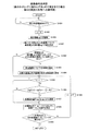
図14は、上記による第5の実施の形態としての動作を実現するために画像信号処理部10によって実行されるべき処理動作をフローチャート化して示している。
なお、この図14においても一例として、最初の画像に傾きを合わせる第2の実施の形態の補正処理を行う場合に、第5の実施の形態を適用した場合の処理動作を例示する。
FIG. 14 is a flowchart showing the processing operation to be executed by the image
In FIG. 14 as an example, a processing operation in the case where the fifth embodiment is applied when performing the correction processing of the second embodiment in which the inclination is adjusted to the first image is illustrated.
図14において、先ずこの場合は、ステップS801により、n=1にセットした後、ステップS802においてflag=0に設定する。この「flag」は、既に前画像との傾き量aglの差が閾値th2より大となる画像が得られた状態にあるか否かを表すためのステータスフラグとして、この場合の画像信号処理部10が設定するフラグとなる。
In FIG. 14, first, in this case, after setting n = 1 in step S801, flag = 0 is set in step S802. This “flag” is a status flag for indicating whether or not an image in which the difference in the inclination amount agl from the previous image is larger than the threshold value th2 has already been obtained. In this case, the image
そして、上記ステップS802の処理を実行すると、先の図6にて説明したステップS301→ステップS302と同様の処理(この場合はnをカウントする関係から傾き量agl(n)となる)を実行する。そして、ステップS302において、最初の画像であるとして肯定結果が得られた場合は、図6の場合と同様にステップS303で目標傾き量T-aglの設定処理を行った後、ステップS304にて傾き量がT-aglとなるように画像データ(n)の傾きを補正する処理を実行する。さらに、このように補正処理を実行したことに応じ、ステップS305にて補正処理終了通知を行った後、この場合はステップS810にてn=n+1とした後に先のステップS301に戻るようにされる。 When the process of step S802 is executed, the same process as step S301 → step S302 described in FIG. 6 (in this case, the inclination amount agl (n) is obtained from the relationship of counting n) is executed. . If an affirmative result is obtained in step S302 that the image is the first image, the target inclination amount T-agl is set in step S303 as in the case of FIG. 6, and then the inclination is determined in step S304. A process of correcting the inclination of the image data (n) so that the amount becomes T-agl is executed. Further, in response to the execution of the correction process in this way, after a correction process end notification is made in step S305, in this case, after n = n + 1 in step S810, the process returns to the previous step S301. .
一方、上記ステップS302にて、最初の画像ではないとして否定結果が得られた場合は、ステップS803に進み、flag=1であるか否かを判別する。ステップS803において、flag=1ではない(つまり前画像との傾き量aglの差が閾値th2より大となる画像が未だ得られていない)として否定結果が得られた場合は、ステップS804に進んで「|agl(n)−agl(n−1)|>th2」であるか否かを判別する。
ステップS804において、「|agl(n)−agl(n−1)|>th2」ではなく、現在の撮像画像データ(n)の傾き量agl(n)と前の撮像画像データ(n−1)の傾き量agl(n−1)との差が閾値th2より大ではないとして否定結果が得られた場合は、先のステップS304に進んで補正処理を実行する。つまりこれにより、前画像との傾き量aglの差が閾値th2以下となる画像が連続する限りは、設定された目標傾き量T-aglに基づく補正処理が実行され、且つ補正処理後の画像データのストレージ部9への記録が実行されるものとなる。
On the other hand, if a negative result is obtained in step S302 that the image is not the first image, the process proceeds to step S803, where it is determined whether flag = 1. If it is determined in step S803 that flag = 1 is not satisfied (that is, an image in which the difference in inclination agl from the previous image is greater than the threshold value th2 has not yet been obtained), the process proceeds to step S804. It is determined whether or not “| agl (n) −agl (n−1) |> th2”.
In step S804, instead of “| agl (n) −agl (n−1) |> th2”, the inclination amount agl (n) of the current captured image data (n) and the previous captured image data (n−1). If a negative result is obtained on the assumption that the difference from the inclination amount agl (n−1) is not greater than the threshold th2, the process proceeds to the previous step S304 to execute the correction process. In other words, as long as the images in which the difference in the inclination amount agl from the previous image is equal to or smaller than the threshold th2 are continued, the correction processing based on the set target inclination amount T-agl is executed, and the image data after the correction processing is performed. Is recorded in the storage unit 9.
一方、上記ステップS804において、「|agl(n)−agl(n−1)|>th2」であり、現在の撮像画像データ(n)の傾き量agl(n)と前の撮像画像データ(n−1)の傾き量agl(n−1)との差が閾値th2より大であるとの肯定結果が得られた場合は、ステップS805に進んでflag=1に設定した後、ステップS811にてシステムコントローラ2に対する対象外通知を行う。この対象外通知により、前画像との傾き量aglの差が閾値th2より大となる画像が得られた際には、差しあたりその画像についてのストレージ部9への記録が見送られるようになっている。
そして、上記ステップS811により対象外通知を行うと、ステップS812にてn=n+1とした後、先のステップS301に戻るようにされる。
On the other hand, in the above step S804, “| agl (n) −agl (n−1) |> th2”, the inclination amount agl (n) of the current captured image data (n) and the previous captured image data (n If a positive result is obtained that the difference between the inclination amount agl (n-1) of -1) is larger than the threshold value th2, the process proceeds to step S805 and flag = 1 is set, and then in step S811 A non-target notification is sent to the
Then, when the non-target notification is performed in step S811, the process returns to step S301 after n = n + 1 in step S812.
また、上述したステップS803において、flag=1である(つまり前画像との傾き量aglの差が閾値th2より大となる画像が既に得られている)として肯定結果が得られた場合は、ステップS806に進み「|agl(n)−agl(n−1)|>th2」であるか否かを判別する。つまり、このステップS806による判別処理は、前画像との傾き量aglの差が閾値th2より大となる画像が2以上連続して得られたか否かを判別する処理となる。
ステップS806において、「|agl(n)−agl(n−1)|>th2」であるとして肯定結果が得られた場合は、先に説明したステップS811に進んで対象外通知を行う。すなわち、これによって前画像との傾き量aglの差が閾値th2より大となる画像が連続して得られる限りにおいては、それらの画像(画像データ(n)は保留となる)についての補正処理及びストレージ部9への記録が実行されないものとなる。
In step S803 described above, if a positive result is obtained as flag = 1 (that is, an image in which the difference in inclination agl from the previous image is greater than the threshold th2 has already been obtained), step S803 is performed. In step S806, it is determined whether “| agl (n) −agl (n−1) |> th2”. That is, the determination processing in step S806 is processing for determining whether or not two or more images in which the difference in the inclination amount agl from the previous image is larger than the threshold value th2 are obtained continuously.
If an affirmative result is obtained in step S806 that “| agl (n) −agl (n−1) |> th2”, the process proceeds to step S811 described above to make a notification of exclusion. In other words, as long as images having a difference in inclination agl from the previous image greater than the threshold th2 are continuously obtained, correction processing for these images (image data (n) is suspended) and Recording to the storage unit 9 is not executed.
また、上記ステップS806において、「|agl(n)−agl(n−1)|>th2」ではないとして否定結果が得られた場合は、先ずはステップS807にてflag=0に戻すようにされる。つまり、この場合は前画像との傾き量aglの差が閾値th2より大となる画像は1度のみ得られたということになるので、先ずはflag=0にリセットするようにされる。 If a negative result is obtained in step S806 that “| agl (n) −agl (n−1) |> th2” is not satisfied, first, flag = 0 is returned to step S807. The In other words, in this case, an image in which the difference in the amount of inclination agl from the previous image is greater than the threshold th2 is obtained only once, so the flag is first reset to 0.
そして、続くステップS808において、目標傾き量T-aglを前回取得したagl(n−1)に変更した上で、次のステップS809において傾き量がT-aglとなるように画像データ(n),画像データ(n−1)の傾きを補正する。
その上で、ステップS305においてシステムコントローラ2への補正処理終了通知を行う。
In subsequent step S808, the target inclination amount T-agl is changed to the previously acquired agl (n-1), and in the next step S809, the image data (n), The inclination of the image data (n-1) is corrected.
After that, in step S305, the
このような処理が実行されることで、前画像との傾き量aglの差が閾値th2より大となる画像が連続しなかった場合には、目標傾き量T-aglが、上記画像データ(n−1)について検出された傾き量agl(n−1)に変更されて上記画像データ(n−1)・画像データ(n)についての補正処理が実行されると共に、補正処理されたこれら画像データ(n−1)・画像データ(n)がストレージ部9に対して記録されるものとなる。
つまりこの結果、傾き量aglが大きく変化した画像データ(x)が得られ、以降の画像が前画像との傾き量aglの差が閾値th2以下に収まる限りは、目標傾き量T-aglが上記画像データ(x)の傾き量agl(x)に変更された上で、上記画像データ(x)以降の画像についての傾き補正が行われるものとなる。
By executing such processing, when images having a difference in inclination amount agl from the previous image that is greater than the threshold value th2 are not consecutive, the target inclination amount T-agl is determined from the image data (n The image data (n-1) and the image data (n) are corrected by changing to the inclination amount agl (n-1) detected for -1), and the corrected image data (N−1) Image data (n) is recorded in the storage unit 9.
That is, as a result, image data (x) in which the inclination amount agl changes greatly is obtained, and the target inclination amount T-agl is the above as long as the difference between the subsequent images and the inclination amount agl is less than or equal to the threshold th2. After the inclination amount agl (x) of the image data (x) is changed, the inclination correction is performed on the image data after the image data (x).
なお、図14においては第5の実施の形態を第2の実施の形態の補正処理が行われる場合に適用する例のみを示したが、例えば第1の実施の形態の補正処理が行われる場合に適用するときは、初期値としての目標傾き量T-aglを「0」とした上で、図14に示されるステップS302にて肯定結果が得られた場合にそのままステップS304の処理に進むように処理動作を変更すればよい。
或いは、第3の実施の形態の補正処理を行う場合に適用するとしたときは、図14に示されるステップS303は省略した上で、ステップS302にて肯定結果が得られた場合、及びステップS804にて否定結果が得られた場合に続く処理として、先の図7に示したステップS403→S404の処理を実行した後に、ステップS304の補正処理が実行されるようにすればよい。
なお、このように第3の実施の形態の補正処理が行われる場合に適用するとしたときにおいて、ステップS808による目標傾き量T-aglの変更後も平均値aveを算出するとした場合には、それまでの平均値aveの算出値は1度リセットする。すなわち、このようにして平均値aveの算出値をリセットした上で、上記ステップS808によるT-aglの変更が行われた以降で得られる画像データの傾き量aglに基づく平均値aveを順次算出し、当該算出される平均値aveが目標傾き量T-aglとされるように処理動作を変更するものとすればよい。
このようにすることで、ステップS808による目標傾き量T-aglの変更後、前画像との傾き量aglの差が閾値th2を超えない複数の画像が連続する場合には、それらの画像の平均値aveに合わせるようにして各画像の補正処理を行うことができる。
FIG. 14 shows only an example in which the fifth embodiment is applied when the correction process according to the second embodiment is performed. For example, when the correction process according to the first embodiment is performed. When applying to the above, if the target inclination amount T-agl as an initial value is set to “0”, and if an affirmative result is obtained in step S302 shown in FIG. 14, the process proceeds to step S304 as it is. The processing operation may be changed to
Alternatively, when it is applied to the correction process of the third embodiment, step S303 shown in FIG. 14 is omitted, and a positive result is obtained in step S302, and step S804 is entered. As a process subsequent to the case where a negative result is obtained, the correction process of step S304 may be executed after executing the process of steps S403 → S404 shown in FIG.
In addition, when it is applied to the case where the correction process of the third embodiment is performed in this way, when the average value ave is calculated even after the target inclination amount T-agl is changed in step S808, The calculated value of the average value ave until is reset once. That is, after the calculated value of the average value ave is reset in this way, the average value ave based on the inclination amount agl of the image data obtained after the change of T-agl in step S808 is sequentially calculated. The processing operation may be changed so that the calculated average value ave is the target inclination amount T-agl.
By doing in this way, after the change of the target inclination amount T-agl in step S808, if a plurality of images whose difference in inclination amount agl from the previous image does not exceed the threshold th2 are consecutive, the average of those images Each image can be corrected so as to match the value ave.
また、第5の実施の形態としては、先の第4の実施の形態を組み合わせることもできる。その場合、例えば図14におけるステップS303とステップS304の間と、ステップS302とステップS804の間の双方など、現在の取り込み撮像画像データ(n)についての傾き量agl(n)が取得され且つ目標傾き量T-aglが設定された以降であって、少なくとも撮像画像データ(n)についての補正処理が実行される前のまでの間に、先の図12のステップS701を挿入する。そして、当該ステップS701にて肯定結果が得られた場合に、ステップS811における対象外通知が実行されるようにすればよい。これによって、第5の実施の形態においても傾き補正量が閾値th1より大となる画像について傾き補正・記録の対象外とすることができる。
Further, as the fifth embodiment, the previous fourth embodiment can be combined. In that case, for example, between step S303 and step S304 in FIG. 14 and between step S302 and step S804, the amount of inclination agl (n) for the current captured image data (n) is acquired and the target inclination is obtained. Step S701 in FIG. 12 is inserted after the amount T-agl has been set and before the correction processing for the captured image data (n) is executed. Then, if a positive result is obtained in step S701, the non-target notification in step S811 may be executed. Thereby, also in the fifth embodiment, an image whose inclination correction amount is larger than the threshold value th1 can be excluded from inclination correction and recording.
<第6の実施の形態>
ここで、これまでの各実施の形態では、自動撮像された画像データについての再生画像の揺れの発生を防止する上で、自動撮像画像データに対して傾き補正を施した上でストレージ部9に記録するものとしたが、第6の実施の形態は、記録時には撮像画像データに対する補正処理は行わず、ストレージ部9には撮像画像データと傾き量aglの情報を記録するものとし、このように記録された撮像画像データの再生時において傾き量aglの情報に基づく補正処理を実行するものである。
なお、第6の実施の形態としても、撮像装置1の構成については先の図1、図2に示したものと同様となるので改めての図示による説明は省略する。
<Sixth Embodiment>
Here, in each of the embodiments so far, in order to prevent occurrence of a shake of a reproduced image with respect to automatically captured image data, the storage unit 9 is subjected to inclination correction on the automatically captured image data. In the sixth embodiment, the captured image data is not corrected at the time of recording, and the storage unit 9 records the captured image data and the information about the tilt amount agl. When the recorded captured image data is reproduced, correction processing based on the information of the inclination amount agl is executed.
In the sixth embodiment as well, the configuration of the
[記録時の処理]
図15は、第6の実施の形態の場合のシステムコントローラ2によって、撮像画像の記録時に対応して実行されるべき処理動作について示したフローチャートである。
図15において、この場合のシステムコントローラ2としても、撮像画像データの記録時に対応しては、先の図4に示したステップS101〜S103と同様の処理によって撮像タイミングの待機処理・撮像画像データの取込制御処理・傾き情報の取得処理を実行するようにされる。
そして、この場合は、ステップS103による傾き情報の取得処理を行った後に、ステップS901において、取り込んだ画像データと傾き情報とが対応づけられるようにしてストレージ部9に記録されるように制御処理を行うようにされる。例えば、この場合のシステムコントローラ2は、ストレージ部9に対し、取り込んだ撮像画像データを識別するためのIDと、取得した傾き量aglの情報とを対応関係を示すための管理情報を生成していくものとされる。ステップS901では、取り込んだ撮像画像データについてのストレージ部9への記録制御を行うと共に、上記管理情報の内容を、取り込んだ撮像画像データについてのIDと取得した傾き量aglの情報とに基づき更新する処理を実行する。
このステップS901の処理を実行すると、ステップS101に戻るようにされる。
[Processing during recording]
FIG. 15 is a flowchart illustrating processing operations to be executed by the
In FIG. 15, the
In this case, after performing the inclination information acquisition process in step S103, in step S901, the control process is performed so that the captured image data and the inclination information are associated with each other and recorded in the storage unit 9. To be done. For example, the
When the process of step S901 is executed, the process returns to step S101.
[再生時の処理:1表示タイミングごとに補正を行う場合]
続いて、図16のフローチャートは、この場合のシステムコントローラ2によって画像の再生時(再生表示時)に対応して行われるべき処理動作を示している。
先ず、前提として、画像再生時に傾き補正処理を実行する第6の実施の形態としては、画像信号処理部10による補正処理として、先に説明した各実施の形態の補正処理を組み合わせることができる。但し、システムコントローラ2の処理内容としては、第1〜第3の実施の形態のように撮像画像データのすべてを補正対象とするか、或いは第4の実施の形態のように補正対象から除外する撮像画像データがあるかで異なるものとなる。
図16では、第1〜第3の実施の形態のように撮像画像データのすべてを補正対象とする場合に対応して行われるべき処理動作を示している。
また、この図16では一例として、画像データの1表示タイミングごとに画像信号処理部10における1画像についての補正処理が実行される場合に対応した処理動作を示す。
[Processing during playback: When correcting at each display timing]
Subsequently, the flowchart of FIG. 16 shows processing operations to be performed by the
First, as a premise, in the sixth embodiment in which the inclination correction process is executed at the time of image reproduction, the correction process of each embodiment described above can be combined as the correction process by the image
FIG. 16 shows processing operations to be performed in correspondence with the case where all of the captured image data is to be corrected as in the first to third embodiments.
FIG. 16 shows, as an example, processing operations corresponding to a case where correction processing for one image in the image
図16において、先ずステップS1001では、操作入力部7からの操作入力として、ストレージ部9に記録された撮像画像データについての再生表示の開始を指示する操作入力を待機する。
ここで、上記再生指示としては、ストレージ部9に記録される撮像画像データについての再生範囲も指示するものであるとする。この場合、再生範囲としては、ストレージ部9に記録されるすべての撮像画像データとされてもよいし、或いは所要のフォルダ内のすべての撮像画像データなど、ストレージ部9に記録される全撮像画像データのうちの所要の一部のみが指定されてもよい。
In FIG. 16, first, in step S <b> 1001, as an operation input from the operation input unit 7, an operation input instructing the start of reproduction display for the captured image data recorded in the storage unit 9 is waited.
Here, it is assumed that as the reproduction instruction, a reproduction range for captured image data recorded in the storage unit 9 is also instructed. In this case, the reproduction range may be all captured image data recorded in the storage unit 9, or all captured images recorded in the storage unit 9, such as all captured image data in a required folder. Only a required part of the data may be specified.
上記再生指示があったとした場合は、ステップS1002において、z=表示すべき画像のIDとする。ここで、上記再生指示が行われることによっては、再生範囲が指定され、最初に表示すべき撮像画像データが決定される。ステップS1002では、このように決定された最初に表示すべき撮像画像データのIDをzの値として設定する。 If it is determined that the reproduction instruction has been given, in step S1002, z = ID of an image to be displayed. Here, when the reproduction instruction is given, a reproduction range is designated, and the captured image data to be displayed first is determined. In step S1002, the ID of the captured image data to be displayed first determined as described above is set as the value of z.
続くステップS1003では、ストレージ部9に記録される画像データ(z)を一時メモリ14に保持させる。すなわち、ストレージ部9に記録される撮像画像データのうちから、表示すべきとされる撮像画像データ(z)を読み出し、これを一時メモリ14に保持させる。
そして、次のステップS1004では、ストレージ部9に記録される傾き量agl(z)を画像信号処理部10に転送する。つまり、表示すべきとされる撮像画像データ(z)と対応づけられている傾き量agl(z)をストレージ部9から読み出し、これを画像信号処理部10に転送する。
In subsequent step S1003, the image data (z) recorded in the storage unit 9 is held in the
In step S1004, the inclination amount agl (z) recorded in the storage unit 9 is transferred to the image
続くステップS1005では、画像信号処理部10からの補正処理終了通知を待機する。
そして、補正処理終了通知があった場合は、ステップS1006において、補正処理された画像データ(z)についての表示制御処理を行う。すなわち、一時メモリ14に保持される画像信号処理部10による補正処理後の画像データ(z)を、表示制御部6に供給して表示部6上に表示させるように指示を行う。
In the subsequent step S1005, a correction processing end notification from the image
If a correction processing end notification is received, display control processing is performed on the corrected image data (z) in step S1006. That is, the image data (z) corrected by the image
続くステップS1007では、再生終了トリガが発生したか否かを判別する。つまり、例えば再生停止を指示する操作入力など、予め撮像画像データの再生表示動作を終了すべきとして設定された所定条件が成立したか否かを判別する。
ステップS1007において、再生終了トリガが発生していないとして否定結果が得られた場合は、ステップS1008に進んで画像送りトリガが発生したか否かを判別する。すなわち、例えば表示画像の送りを指示する操作入力や、或いは自動再生を想定した場合には所定時間の経過など、予め表示画像を送るべきとして定められた所定条件が成立したか否かを判別する。このステップS1008において、画像送りトリガが発生していないとして否定結果が得られた場合は、上記ステップS1007に戻るようにされる。
これらステップS1007→S1008→1007のループ処理により、再生終了トリガの発生、または画像送りトリガの発生の何れかを待機するようにされている。
In a succeeding step S1007, it is determined whether or not a reproduction end trigger has occurred. That is, it is determined whether or not a predetermined condition set in advance to end the reproduction display operation of the captured image data, such as an operation input instructing to stop the reproduction, is determined.
If a negative result is obtained in step S1007 that a playback end trigger has not occurred, the process proceeds to step S1008 to determine whether an image feed trigger has occurred. That is, for example, it is determined whether or not a predetermined condition that is determined in advance to send the display image, such as an operation input instructing the display image to be sent, or a predetermined time when the automatic reproduction is assumed, is satisfied. . If a negative result is obtained in step S1008 that no image feed trigger has occurred, the process returns to step S1007.
By the loop processing of these steps S1007 → S1008 → 1007, either the generation of the playback end trigger or the generation of the image feed trigger is waited.
上記ステップS1008において、画像送りトリガが発生したとして肯定結果が得られた場合は、ステップS1009に進んでz=次に表示すべき画像のIDとした上で、先のステップS1003に戻るようにされる。これによって、表示すべき画像データについて、その補正後画像を順次再生表示させることができる。 If an affirmative result is obtained in step S1008 that an image feed trigger has occurred, the process advances to step S1009 to set z = the ID of the image to be displayed next, and then returns to step S1003. The As a result, the corrected image can be sequentially reproduced and displayed for the image data to be displayed.
また、上記ステップS1007において、再生終了トリガが発生したとして肯定結果が得られた場合は、図示するようにしてこの図に示す処理動作は終了となる。 If a positive result is obtained in step S1007 that a playback end trigger has occurred, the processing operation shown in this figure ends as shown in the figure.
ここで、確認のために、図16に示したシステムコントローラ2の処理動作に対応して画像信号処理部10にて行われるべき処理動作を、次の図17に示すフローチャートを参照して説明する。
この図17では一例として、目標傾き量T-agl=0とする第1の実施の形態の補正処理を行う場合に対応した処理動作を示している。
先ず、この場合は、ステップS1101において、先の図16のステップS1004によってシステムコントローラ2から転送される傾き量agl(z)を取得するようにされる。
そして、続くステップS1102では、目標傾き量T-aglとなるように画像データ(z)の傾きを補正するようにされる。
さらに、次のステップS1103においてシステムコントローラ2に対する補正処理終了通知を行った後、ステップS1101に戻るようにされる。
Here, for confirmation, the processing operation to be performed in the image
In FIG. 17, as an example, a processing operation corresponding to the case where the correction processing of the first embodiment in which the target inclination amount T-agl = 0 is performed is shown.
First, in this case, in step S1101, the inclination amount agl (z) transferred from the
In subsequent step S1102, the inclination of the image data (z) is corrected so as to be the target inclination amount T-agl.
In step S1103, the
なお、第2の実施の形態のように最初の画像の傾き量に合わせて補正処理を行う場合の画像信号処理部10の処理動作としては、先の図6に示したステップS301において、上記ステップS1101と同様にシステムコントローラ2から転送される傾き量agl(z)を取得するものとすればよい。
同様に、第3の実施の形態のように平均値aveに合わせて補正処理を行う場合には、先の図7(または図9)におけるステップS402においてシステムコントローラ2から転送される傾き量agl(z)を取得することになる。この場合、画像信号処理部10ではnの値をカウントするが、zの値としてはあくまでシステムコントローラ2側で管理する値であるので、画像信号処理部10側においては、取得された傾き量aglを傾き量(n)とすることに変わりはない。またこのことは画像データについての(z)と(n)の関係についても同様である。
Note that the processing operation of the image
Similarly, when the correction process is performed in accordance with the average value ave as in the third embodiment, the inclination amount agl () transferred from the
続いて、図18のフローチャートにより、第4の実施の形態のように対象外とする画像がある場合に対応して、画像再生時(再生表示時)にシステムコントローラ2により行われるべき処理動作を説明する。
なおこの図18において、既に先の図16にて説明したものと同様となる処理については同一ステップ番号を付して説明を省略する。
Subsequently, according to the flowchart of FIG. 18, the processing operation to be performed by the
In FIG. 18, the same steps as those already described with reference to FIG. 16 are given the same step numbers and description thereof is omitted.
この図18に示されるようにして、対象外とする画像がある場合に対応しては、先の図16に示した処理動作に対し、画像信号処理部10側からの補正処理終了通知、または対象外通知の何れかを待機する処理を設けるようにする。つまりこの場合、ステップS1005にて補正処理終了通知が為されていないとして否定結果が得られた場合は、ステップS1201に進み、画像信号処理部10側からの対象外通知が行われたか否かを判別する。そして、当該ステップS1201において対象外通知が行われていないとして否定結果が得られた場合は、ステップS1005に戻るようにされる。
その上で、上記ステップS1201にて対象外通知が行われたとして肯定結果が得られた場合は、図示するようにしてステップS1006による補正処理をパスさせて、ステップS1007に進むようにする。
これにより、対象外とされた画像データについての表示が行われないようにすることができる。
As shown in FIG. 18, in response to a case where there is an image to be excluded, a correction processing end notification from the image
In addition, if an affirmative result is obtained in step S1201 that the notification of exclusion is performed, the correction process in step S1006 is passed as shown in the figure, and the process proceeds to step S1007.
As a result, it is possible to prevent display of image data that is not targeted.
なお、確認のために述べておくと、この場合に対応して画像信号処理部10により実行されるべき処理動作について、第4の実施の形態の補正処理を行う場合に対応した処理動作としては、先の図12に示したステップS301において、ステップS1004によりシステムコントローラ2側から転送される傾き量agl(z)を取得することになる。
For confirmation, the processing operation to be executed by the image
ここで、注意すべきは、図18に示されるように1表示タイミングごとに補正を行う場合に対応した処理動作をシステムコントローラ2が行うようにした場合は、第5の実施の形態を組み合わせることができないという点である。
具体的に、先の図14は記録時に対応した処理動作であることから、ステップS811によってシステムコントローラ2側に対象外通知を行ったとしても、次の画像(n)として前画像との傾き量aglの差が閾値th2以下の画像が得られれば、画像(n)と画像(n−1)の双方について補正が行われて、これらを記録することができたが、図18のシステムコントローラ2側の処理動作によると、対象外通知が行われた画像については表示制御が行われず、直ちに次の画像についての処理に移行されてしまうものとなる。つまりこのことで、本来表示されるべき画像についての表示が行われなくなってしまうものである。
なお、このように第5の実施の形態の補正処理を行う場合に対応して適正に画像表示を行う手法については後述する。
Here, it should be noted that when the
Specifically, since FIG. 14 is a processing operation corresponding to the time of recording, even if a non-target notification is sent to the
Note that a method for appropriately displaying an image corresponding to the case where the correction process of the fifth embodiment is performed will be described later.
[再生時の処理:表示タイミングに関わらずまとめて補正を行う場合]
これまでの説明では、再生時の処理動作として、1表示タイミングごとに1画像についての補正が行われることを前提とした場合の処理動作を説明したが、第6の実施の形態の場合、記録時に補正を行う場合とは異なり、補正対象となる撮像画像データ(及びその傾き量aglの情報)は全てストレージ部9に格納されている状態にある。
このことに鑑み、第6の実施の形態としては、表示タイミングに関わらず或る程度の数の画像データをまとめて画像信号処理部10により補正させるようにすることもできる。
[Processing during playback: When performing corrections at once regardless of the display timing]
In the description so far, the processing operation when it is assumed that the correction for one image is performed at every display timing as the processing operation at the time of reproduction has been described. However, in the case of the sixth embodiment, recording is performed. Unlike the case where correction is sometimes performed, all of the captured image data (and information on the inclination amount agl) to be corrected is stored in the storage unit 9.
In view of this, in the sixth embodiment, a certain number of image data can be collectively corrected by the image
図19,図20は、このように表示タイミングに関わらずまとめて補正を行う場合に対応してシステムコントローラ2により行われるべき処理動作を示している。
なお、この場合としても、システムコントローラ2によって実行されるべき処理動作は、画像信号処理部10にて全画像を対象として補正処理を行うか否か(つまり対象外とする画像があるか否か)で異なることから、各場合に分けて説明を行うものとする。
図19,図20は、第1〜第3の実施の形態の場合のように、全画像を対象として補正処理が行われることを前提とした場合に対応して行われるべき処理動作を示している。
19 and 20 show processing operations to be performed by the
Even in this case, the processing operation to be executed by the
FIG. 19 and FIG. 20 show processing operations that should be performed in response to the assumption that correction processing is performed on all images, as in the first to third embodiments. Yes.
ここで、先ず前提として、この場合は一時メモリ14に対して複数の撮像画像データをバッファリングさせ、当該バッファリングさせた撮像画像データについて画像信号処理部10にまとめて補正処理を実行させるという手法を採るものとする。その上で、このように補正処理された撮像画像データのうちの、表示すべき撮像画像データについて表示制御を行うものとする。
Here, as a premise, in this case, a method of buffering a plurality of captured image data in the
図19では、上記のような動作の実現にあたり、システムコントローラ2によって行われるべき一時メモリ14への画像データのバッファリング制御、及び画像信号処理部10に対する補正処理実行制御に係る処理動作を示している。
また、図20は、一時メモリ14に保持される補正処理後の撮像画像データについての表示制御に係る処理動作を示している。
この場合のシステムコントローラ2は、再生時において、これらの図に示される処理動作を並行して行うものとなる。
FIG. 19 shows processing operations related to buffering control of image data to the
FIG. 20 shows a processing operation related to display control for captured image data after correction processing held in the
In this case, the
先ずは、図19に示される処理動作から説明する。
図19において、先ずステップS1001では、先の図16のステップS1001と同様に再生指示を待機する。そして、再生指示があった場合は、ステップS1301において、補正のために一時メモリ14に保持させる画像データを決定する処理を行う。例えば、上記再生指示によって指示される再生範囲内において最初に表示すべきとされる撮像画像データを含む10枚分程度の撮像画像データなど、少なくとも上記再生指示に応じ最初に表示が行われるべき撮像画像データを含む複数枚分の撮像画像データを決定する。
なお、このステップS1301による決定処理について、例えば画像送りとして順送りのみが想定される場合には、最初に表示すべき画像とそれ以降の所定枚数分の画像データを決定すればよい。或いは、画像送りとして逆送りも可能とされることを想定した場合には、最初に表示すべき画像を基準としてその前後の複数枚分の画像データを決定することもできる。
First, the processing operation shown in FIG. 19 will be described.
In FIG. 19, first in step S1001, a reproduction instruction is waited in the same manner as in step S1001 of FIG. If there is a reproduction instruction, in step S1301, processing for determining image data to be held in the
In the determination process in step S1301, for example, when only forward feeding is assumed as image feeding, the first image to be displayed and a predetermined number of image data after that may be decided. Alternatively, when it is assumed that reverse feeding is possible as image feed, it is also possible to determine image data for a plurality of images before and after the image to be displayed first.
続くステップS1302では、決定された画像データを一時メモリ14に保持させる処理を行う。すなわち、ストレージ部9に記録される撮像画像データのうちから上記ステップS1301にて決定した撮像画像データを読み出させ、それらを一時メモリ14に保持させる。
In a succeeding step S1302, a process for holding the determined image data in the
そして、次のステップS1303では、画像信号処理部10に対する補正処理開始指示を行い、その上で、ステップS1304において、一時メモリ14に保持させた画像データの傾き量aglの情報を画像信号処理部10に対して転送する。
Then, in the next step S1303, an instruction to start correction processing is given to the image
続くステップS1305では、保持画像追加トリガが発生したか否かを判別する。すなわち、例えば一時メモリ14に保持される補正後画像データの残り数が所定値以下となるなど、一時メモリ14への保持画像を追加すべきとして予め設定された所定条件が成立したか否かを判別する。
ステップS1305において、保持画像追加トリガが発生していないとして否定結果が得られた場合は、先の図16の場合と同様のステップS1007の処理により、再生終了トリガが発生したか否かを判別し、当該ステップS1007にて再生終了トリガが発生していないとして否定結果が得られた場合は、上記ステップS1305に戻るようにされる。すなわち、これらステップS1305・S1007により、保持画像追加トリガの発生、再生終了トリガの発生の何れかを待機するようにされている。
この場合も上記ステップS1007にて肯定結果が得られた場合には処理動作を終了する。
In the subsequent step S1305, it is determined whether or not a retained image addition trigger has occurred. That is, for example, whether or not a predetermined condition that is set in advance so that a retained image in the
If a negative result is obtained in step S1305 that the retained image addition trigger has not occurred, it is determined whether or not a playback end trigger has occurred by the processing in step S1007 similar to the case of FIG. If a negative result is obtained in step S1007 that the playback end trigger has not occurred, the process returns to step S1305. That is, by these steps S1305 and S1007, either the generation of the retained image addition trigger or the generation of the reproduction end trigger is waited.
Also in this case, if a positive result is obtained in step S1007, the processing operation is terminated.
そして、上記ステップS1305において、保持画像追加トリガが発生したとして肯定結果が得られた場合は、ステップS1306に進んで追加すべき画像データを決定する。具体的に、例えば画像送りとして順送りのみが想定される場合には、一時メモリ14に保持させた画像データ群に対し順送り方向に隣接する所定枚数分の画像データを決定すればよい。或いは、画像送りとして逆送りも可能とされることを想定した場合には、一時メモリ14に保持させた画像データ群を基準として、画像不足となった送り方向に隣接する複数枚分の画像データを決定するものとすればよい。
ステップS1306の処理を実行すると先のステップS1302に戻るようにされる。これにより、決定した画像データの一時メモリ14への追加が行われる。
If a positive result is obtained in step S1305 that a retained image addition trigger has occurred, the process proceeds to step S1306 to determine image data to be added. Specifically, for example, when only forward feed is assumed as image feed, a predetermined number of image data adjacent in the forward feed direction to the image data group held in the
When the process of step S1306 is executed, the process returns to the previous step S1302. As a result, the determined image data is added to the
続いて、図20に示される処理動作について説明する。
この図20に示される、補正画像の表示制御に係る処理としては、先の図16にて説明した処理動作と比較して、ステップS1003による画像データの一時メモリ14への保持処理、及びステップS1004による傾き情報の転送処理、及びステップS1005による補正終了通知の待機処理が省略されたものとなる。この場合は、図示するようにしてステップS1002とステップS1006との間に、ステップS1401の処理が追加されたものとなる。
なおこの図20において、既に図16にて説明したものと同様となる処理については同一ステップ番号を付して説明は省略する。
Next, the processing operation shown in FIG. 20 will be described.
As processing relating to display control of the corrected image shown in FIG. 20, compared with the processing operation described in FIG. 16, the retention processing of the image data in the
In FIG. 20, the same steps as those already described with reference to FIG.
上記ステップS1401では、一時メモリ14内に画像(z)の補正後画像が得られるまで待機するようにされる。そして、一時メモリ14内に画像(z)についての補正後画像があるとした場合には、ステップS1006による表示制御を行うようにされる。
なお、確認のために述べておくと、この場合においてステップS1009によりz=次に表示すべき画像のIDに設定すると、ステップS1401に戻ることになる。
In step S1401, the process waits until a corrected image of the image (z) is obtained in the
For confirmation, in this case, if z is set to the ID of the image to be displayed next in step S1009, the process returns to step S1401.
次に、図19、図20に示されるシステムコントローラ2による処理動作が行われる場合に対応して、画像信号処理部10側にて実行されるべき処理動作について、次の図21のフローチャートを参照して説明する。
この図21では、一例として第1の実施の形態のように目標傾き量T-agl=0として補正を行う場合に対応した処理動作を示す。
Next, the processing operation to be executed on the image
In FIG. 21, as an example, a processing operation corresponding to a case where correction is performed with the target inclination amount T-agl = 0 as in the first embodiment is shown.
図21において、先ずステップS1501では補正処理開始指示を待機する。すなわち、先の図19のステップS1303にてシステムコントローラ2によって行われる補正処理開始指示を待機する。
そして、当該補正処理開始指示があった場合には、ステップS1502において、先ずは変数n=1に設定を行う。この変数nとしては、画像信号処理部10側で一時メモリ14に保持された画像データのうちから補正対象とする画像データを決定するための値となる。
In FIG. 21, first, in step S1501, a correction process start instruction is awaited. That is, it waits for the correction processing start instruction performed by the
If there is an instruction to start the correction process, first, in step S1502, a variable n = 1 is set. The variable n is a value for determining image data to be corrected from image data held in the
続くステップS1503では、傾き量aglの情報を取得するようにされる。すなわち、先の図19のステップS1304によりシステムコントローラ2が転送する傾き量aglの情報(一時メモリ14に保持された各画像データの傾き量aglの情報)を取得するものである。
In subsequent step S1503, information on the tilt amount agl is acquired. That is, information on the inclination amount agl transferred by the
次のステップS1504では、目標傾き量T-agl=0となるように画像データ(n)の傾きを補正する。
そして、続くステップS1505では、一時保持された全画像データについての補正が完了したか否かについて判別を行う。一時メモリ14に保持された全画像データについての補正が完了していないとして否定結果が得られた場合は、ステップS1506にてn=n+1とした後、ステップS1504に戻るようにされる。
一方、上記ステップS1505において一時メモリ14に保持された全画像データについての補正が完了したとして肯定結果が得られた場合は、図示するようにして「RETURN」となる。
In the next step S1504, the inclination of the image data (n) is corrected so that the target inclination amount T-agl = 0.
In subsequent step S1505, it is determined whether or not the correction for all the temporarily stored image data has been completed. If a negative result is obtained that correction for all the image data held in the
On the other hand, when a positive result is obtained in step S1505 that correction for all the image data held in the
このような図21の処理により、画像信号処理部10側では、システムコントローラ2の制御によって一時メモリ14に保持された画像データについて、画像表示タイミングに関わらずまとめて補正処理を行うようにされる。そして、システムコントローラ2により一時メモリ14に新たな画像データが保持された場合は、システムコントローラ2からの補正処理開始指示により図21の処理が再度開始され、これによって再生終了トリガの発生まで適正に補正画像の送り表示を行うことができるものとなる。
21, the image
なお、ここでは第1の実施の形態の補正処理を行う場合に対応するとしたときの画像信号処理部10の処理動作のみを例示したが、第2の実施の形態の補正処理を行う場合に対応した画像信号処理部10の処理動作としては、図21の一連に処理動作について、ステップS1503の傾き情報の取得処理に続く処理として、最初の画像データ(再生指示後の最初の画像データ)であるか否かを判別する処理を挿入するものとし、当該判別処理にて、最初の画像であるとされた場合は、目標傾き量T-aglを画像データ(n)の傾き量aglに設定する処理を経てステップS1504の補正処理として目標傾き量T-aglとなるように補正を行うようにする。一方、最初の画像でないとされた場合には、そのままステップS1504の補正処理として目標傾き量T-aglとなるように補正を行う処理を実行する。
また、第3の実施の形態の補正処理を行う場合に対応した画像信号処理部10の処理動作としては、図21におけるステップS1504の処理に代えて、先の図7に示したステップS403〜S405の処理を挿入するものとすればよい。
Here, only the processing operation of the image
Further, as the processing operation of the image
続いては、第4、第5の実施の形態の場合のように対象外とする画像がある場合に対応して実行されるべき処理動作について説明する。
このように対象外とする画像がある場合に対応してシステムコントローラ2により実行されるべき処理動作として、一時メモリ14へのバッファリング制御・画像信号処理部10に対する補正処理実行制御に係る処理動作、及び補正画像の表示制御に係る処理動作は、先の図19、図20に示したものと同様となり、ここでの改めての図示による説明は省略する。
この場合のシステムコントローラ2によっては、先の図19、図20に示した処理動作と共に、次の図22に示される処理動作をさらに並行して行うようにされる。
Subsequently, processing operations to be executed in response to a case where there is an image that is not a target as in the case of the fourth and fifth embodiments will be described.
Processing operations related to buffering control to the
Depending on the
図22において、先ずステップS1601では、この場合の画像信号処理部10によって行われる対象外画像の通知を待機する。この対象外画像の通知は、後述する画像信号処理部10側の処理動作に伴い行われるものとなり、対象外とする画像をシステムコントローラ2側に指示するための通知となる。
In FIG. 22, first, in step S1601, the notification of the non-target image performed by the image
そして、上記対象外画像の通知があった場合は、ステップS1602において、通知された画像を表示対象外画像に設定する処理を行う。このステップS1602により表示対象外画像に設定された画像については、先の図20におけるステップS1002及びステップS1009の処理における表示対象画像データ(z)の決定の対象から除外されるものとなる。これにより、対象外とされた画像についての表示が行われないようにすることができる。
ステップS1602の処理を実行すると、図示するようにして「RETURN」となる。
If there is a notification of the non-target image, processing for setting the notified image as a non-display target image is performed in step S1602. The image set as the non-display target image in step S1602 is excluded from the determination target of the display target image data (z) in the processing of step S1002 and step S1009 in FIG. As a result, it is possible to prevent display of images that are not targeted.
When the process of step S1602 is executed, “RETURN” is obtained as illustrated.
図23、図24は、上述のようにしてシステムコントローラ2によって図19、図20、図22の並行処理が行われる場合に対応して、画像信号処理部10により実行されるべき処理動作をフローチャート化して示している。
図23は、第4の実施の形態のように傾き補正量が閾値th1より大となる画像を対象外とする場合に対応して行われるべき処理動作を示し、図24は、第5の実施の形態のように前画像との傾き量aglの差に基づいて目標傾き量T-aglを変更・画像を対象外とする場合に対応して行われるべき処理動作を示している。
23 and 24 are flowcharts of processing operations to be executed by the image
FIG. 23 shows processing operations to be performed in response to a case where an image whose inclination correction amount is larger than the threshold th1 is excluded as in the fourth embodiment, and FIG. 24 shows the fifth embodiment. The processing operation to be performed corresponding to the case where the target tilt amount T-agl is changed based on the difference of the tilt amount agl from the previous image and the image is excluded as shown in FIG.
先ずは、図23を参照して、第4の実施の形態に対応する場合の処理動作から説明する。
なお、この図において、目標傾き量T-aglは、例えば第1の実施の形態と同様にT-agl=0に設定されているものとする。
図23において、この場合の画像信号処理部10では、先ずは先の図21にて説明したものと同様のステップS1501〜S1503の処理を実行し、補正処理開始指示に応じてn=1とする処理、及び一時メモリ14に保持された画像データの傾き量aglの情報を取得する処理を実行するようにされる。
First, with reference to FIG. 23, the processing operation in the case of corresponding to the fourth embodiment will be described.
In this figure, it is assumed that the target inclination amount T-agl is set to T-agl = 0, for example, as in the first embodiment.
In FIG. 23, in this case, the image
ここで、この場合の補正処理としては、1表示タイミングにつき1画像について行う必要はない。そこで、上記ステップS1503に続くステップS1701の処理では、一時メモリ14に保持された各画像データの傾き量aglについて、目標傾き量T-aglとの差の計算を行う。すなわち、1表示タイミングにつき1画像について補正を行う場合には、1画像ごとに目標傾き量T-aglとの差を計算するもとしたが、この場合には、一時メモリ14に保持される全画像データについて、目標傾き量T-aglとの差の計算をまとめて行うようにしたものである。
Here, the correction processing in this case need not be performed for one image per display timing. Therefore, in the processing of step S1701 following step S1503, the difference between the inclination amount agl of each image data held in the
そして、続くステップS1702では、上記ステップS1701による計算結果に基づき、目標傾き量T-aglとの差が閾値th1より大となる画像があるか否かを判別する。ステップS1702において、目標傾き量T-aglとの差が閾値th1より大となる画像が無いとして否定結果が得られた場合は、対象外とすべき画像は無いことになるので、図示するようにしてそのままステップS1705に進んで、目標傾き量T-aglとなるように画像データ(n)の傾きを補正する処理を実行する。 In subsequent step S1702, based on the calculation result in step S1701, it is determined whether or not there is an image whose difference from the target inclination amount T-agl is larger than the threshold value th1. If a negative result is obtained in step S1702 that there is no image in which the difference from the target tilt amount T-agl is greater than the threshold th1, there is no image to be excluded. Then, the process directly proceeds to step S1705, and a process of correcting the inclination of the image data (n) so as to become the target inclination amount T-agl is executed.
一方、上記ステップS1702において、目標傾き量T-aglとの差が閾値th1より大となる画像があるとして肯定結果が得られた場合は、ステップS1703に進んで該当画像についての対象外通知を行う。すなわち、目標傾き量T-aglとの差が閾値th1より大となる画像を対象外とするように指示するための通知を、システムコントローラ2に対して行う。
その上で、続くステップS1704では、対象外画像以外の画像を補正対象画像に設定する処理を行う。すなわち、ステップS1703にて通知した画像以外の画像が、自らが行う補正処理の対象画像となるようにして設定を行う。
このステップS1704の処理を実行すると、ステップS1705に処理を進めて画像データ(n)についての補正処理を実行する。
On the other hand, if an affirmative result is obtained in step S1702 that there is an image whose difference from the target tilt amount T-agl is larger than the threshold value th1, the process proceeds to step S1703, and an out-of-target notification is made for the image. . In other words, the
In step S1704, an image other than the non-target image is set as a correction target image. That is, the setting is performed so that an image other than the image notified in step S1703 becomes a target image for correction processing performed by itself.
When the process of step S1704 is executed, the process proceeds to step S1705 to execute a correction process for the image data (n).
ステップS1705の補正処理を実行すると、続くステップS1706において、一時保持された全対象画像データについての補正が完了したか否かを判別する。すなわち、一時メモリ14に保持された画像データのうちの、上記ステップS1704にて補正対象画像に設定した全画像データについての補正処理が完了したか否かを判別する。
ステップS1706において、全対象画像についての補正が未だ完了していないとして否定結果が得られた場合は、ステップS1506にてn=n+1とした後、先のステップS1705に戻るようにされる。また、ステップS1706において、全対象画像についての補正が完了したとして肯定結果が得られた場合は「RETURN」となる。
When the correction process in step S1705 is executed, in the subsequent step S1706, it is determined whether or not the correction for all temporarily held target image data has been completed. That is, it is determined whether or not correction processing has been completed for all image data set in the correction target image in step S1704 among the image data held in the
If a negative result is obtained in step S1706 that correction for all target images has not yet been completed, n = n + 1 is set in step S1506, and then the process returns to the previous step S1705. In step S1706, if a positive result is obtained that correction for all target images has been completed, “RETURN” is set.
なお、この図23では目標傾き量T-agl=0とする場合を例示したが、第2の実施の形態のように目標傾き量T-aglを最初の画像の傾き量aglに合わせる場合には、図23の一連に処理動作について、ステップS1503の傾き情報の取得処理に続く処理として、目標傾き量T-aglを最初の画像データ(再生指示後の最初の画像データ)の傾き量aglに設定する処理を挿入する。その上で、ステップS1701に進むようにすればよい。
また、第3の実施の形態のように目標傾き量T-aglを平均値aveとする場合には、図23におけるステップS1705の処理に代えて、先の図7に示したステップS403〜S405の処理を挿入するものとすればよい。
FIG. 23 illustrates the case where the target tilt amount T-agl = 0, but in the case where the target tilt amount T-agl is matched with the tilt amount agl of the first image as in the second embodiment. In the series of processing operations shown in FIG. 23, as the processing subsequent to the tilt information acquisition processing in step S1503, the target tilt amount T-agl is set to the tilt amount agl of the first image data (first image data after the reproduction instruction). Insert the process to be performed. Then, the process may proceed to step S1701.
Further, when the target inclination amount T-agl is set to the average value ave as in the third embodiment, instead of the process of step S1705 in FIG. 23, the process of steps S403 to S405 shown in FIG. What is necessary is just to insert a process.
続いて、図24により、第5の実施の形態の補正処理を行う場合の画像信号処理部10により行われるべき処理動作について説明する。
なお、この図においても目標傾き量T-agl=0であるとする。
図24において、この場合の画像信号処理部10としても、先ずは先の図21にて説明したものと同様のステップS1501〜S1503の処理を実行し、補正処理開始指示に応じてn=1とする処理、及び一時メモリ14に保持された画像データの傾き量aglの情報を取得する処理を実行するようにされる。
Next, a processing operation to be performed by the image
In this figure, it is assumed that the target inclination amount T-agl = 0.
In FIG. 24, the image
そして、この場合としても、補正処理は1表示タイミングにつき1画像について行う必要はないことから、上記ステップS1503に続くステップS1801の処理としては、一時メモリ14に保持された各画像データについて、まとめて前画像との傾き量aglの差を計算するものとしている。
続くステップS1802では、上記ステップS1801による計算結果に基づき、前画像との傾き量aglの差が閾値th2より大となる画像が連続している部分がある否かを判別する。ステップS1802において、前画像との傾き量aglの差が閾値th2より大となる画像が連続している部分が無いとして否定結果が得られた場合は、後述するステップS1805に処理を進めるようにされる。
Even in this case, since it is not necessary to perform the correction process for one image at one display timing, the process of step S1801 subsequent to step S1503 described above is performed for each image data held in the
In the subsequent step S1802, based on the calculation result in step S1801, it is determined whether or not there is a portion where there is a continuous image in which the difference in inclination agl from the previous image is greater than the threshold th2. If a negative result is obtained in step S1802 that there is no continuous image where the difference in the inclination amount agl from the previous image is greater than the threshold value th2, the process proceeds to step S1805 described later. The
一方、上記ステップS1802において、前画像との傾き量aglの差が閾値th2より大となる画像が連続している部分があるとして肯定結果が得られた場合は、ステップS1803に進んで該当画像についての対象外通知を行う。すなわち、このように前画像との傾き量aglの差が閾値th2より大となる画像が連続している部分の画像データを対象外として指示するための通知を、システムコントローラ2に対して行う。
そして、次のステップS1804において、対象外画像以外の画像を補正対象画像に設定する処理を行った後、ステップS1805に処理を進めるようにされる。
On the other hand, if an affirmative result is obtained in step S1802 that there is a portion in which there is a continuous image in which the difference in the inclination amount agl from the previous image is greater than the threshold value th2, the process proceeds to step S1803 for the corresponding image. Not applicable notification. That is, a notification is given to the
In the next step S1804, a process for setting an image other than the non-target image as the correction target image is performed, and then the process proceeds to step S1805.
ステップS1805では、n=1であるか否かを判別する。n=1であるとされた場合は、ステップS1808に進んで目標傾き量T-aglとなるように画像データ(n)の傾きを補正する処理を行う。
一方、n=1ではないとして否定結果が得られた場合は、ステップS1806に進み、「|agl(n)−agl(n−1)|>th2」であるか否かを判別する。「|agl(n)−agl(n−1)|>th2」ではない(つまり、前画像との傾き量aglの差が閾値th2以下である)として否定結果が得られた場合は、そのままステップS1808の補正処理を実行する。また、「|agl(n)−agl(n−1)|>th2」であるとして肯定結果が得られた場合は、ステップS1807において目標傾き量T-aglを傾き量agl(n)に設定した上で、ステップS1808の補正処理を実行する。
In step S1805, it is determined whether n = 1. If n = 1, the process advances to step S1808 to perform a process of correcting the inclination of the image data (n) so that the target inclination amount T-agl is obtained.
On the other hand, if a negative result is obtained because n = 1 is not satisfied, the process advances to step S1806 to determine whether or not “| agl (n) −agl (n−1) |> th2”. If a negative result is obtained because “| agl (n) −agl (n−1) |> th2” is not satisfied (that is, the difference in the amount of inclination agl from the previous image is equal to or smaller than the threshold th2), the step is performed as it is. The correction process of S1808 is executed. If a positive result is obtained that “| agl (n) −agl (n−1) |> th2”, the target inclination amount T-agl is set to the inclination amount agl (n) in step S1807. Above, the correction process of step S1808 is executed.
ステップS1808の補正処理を実行すると、続くステップS1809において、一時保持された全対象画像データについての補正が完了したか否かを判別する。そして、このステップS1809において、一時メモリ14内の全対象画像についての補正が未だ完了していないとして否定結果が得られた場合は、ステップS1506にてn=n+1とした後、先のステップS1805に戻るようにされる。また、ステップS1809において、全対象画像についての補正が完了したとして肯定結果が得られた場合は「RETURN」となる。
When the correction process in step S1808 is executed, in a subsequent step S1809, it is determined whether or not the correction for all temporarily held target image data has been completed. If a negative result is obtained in step S1809 that correction for all target images in the
ここで確認のために述べておくと、この場合はステップS1802・S1804の処理が実行されることで、以降の処理が実行される際には、既に前画像との傾き量aglの差が閾値th2より大となる画像が連続する部分の画像が補正対象から除外された状態にある。従って、この場合の処理としては、ステップS1806→S1807のように、単に前画像との傾き量aglの差が閾値th2より大となる画像データが現れた時点で、目標傾き量T-aglをその画像データの傾き量aglに変更設定する処理を行えばよいものとなる。 Here, for confirmation, in this case, the processing in steps S1802 and S1804 is executed, and when the subsequent processing is executed, the difference in inclination amount agl from the previous image is already a threshold value. The image of the portion where the images larger than th2 are continuous is excluded from the correction target. Accordingly, as processing in this case, as shown in steps S1806 → S1807, when image data in which the difference in inclination amount agl from the previous image is larger than the threshold value th2 appears, the target inclination amount T-agl is set to It is only necessary to change and set the inclination amount agl of the image data.
なお、この図24においても目標傾き量T-agl=0とする場合を例示したが、第2の実施の形態のように目標傾き量T-aglを最初の画像の傾き量aglに合わせる場合には、図24の一連の処理動作について、ステップS1503の傾き情報の取得処理に続く処理として、目標傾き量T-aglを最初の画像データ(再生指示後の最初の画像データ)の傾き量aglに設定する処理を挿入する。その上で、ステップS1801に進むようにすればよい。
また、第3の実施の形態のように目標傾き量T-aglを平均値aveとする場合には、図24におけるステップS1808の処理に代えて、先の図7に示したステップS403〜S405の処理を挿入するものとすればよい。
In FIG. 24, the target tilt amount T-agl = 0 is exemplified. However, when the target tilt amount T-agl is adjusted to the tilt amount agl of the first image as in the second embodiment. 24, as the processing subsequent to the tilt information acquisition processing in step S1503 in the series of processing operations in FIG. Insert the process to be set. Then, the process may proceed to step S1801.
Further, when the target inclination amount T-agl is set to the average value ave as in the third embodiment, instead of the process of step S1808 in FIG. 24, the process of steps S403 to S405 shown in FIG. What is necessary is just to insert a process.
ここで、以上により説明した第6の実施の形態によれば、記録時には、自動撮像された画像データとその傾き量aglの情報とが対応づけられるようにしてストレージ部9に記録される。そして、このように記録された撮像画像データを再生表示する際に、記録された傾き量aglの情報に基づく傾き補正が行われることになる。 Here, according to the sixth embodiment described above, at the time of recording, the automatically captured image data and the information of the inclination amount agl are recorded in the storage unit 9 so as to be associated with each other. Then, when the captured image data recorded in this way is reproduced and displayed, tilt correction based on the recorded tilt amount agl information is performed.
このような第6の実施の形態によれば、記録時には補正処理が実行されないので、ストレージ部9に対しては補正処理の施されていないオリジナルの画像データを記録することができる。その一方で、記録時には傾き量aglを検出してその情報を画像データと共に記録しているので、再生時にはこの記録された傾き量aglの情報に基づき、画像データの傾き補正を行うことができる。
According to the sixth embodiment, since correction processing is not executed during recording, original image data that has not been subjected to correction processing can be recorded in the storage unit 9. On the other hand, since the tilt amount agl is detected during recording and the information is recorded together with the image data, the tilt correction of the image data can be performed based on the recorded tilt amount agl information during reproduction.
<第7の実施の形態>
図25は、第7の実施の形態としての傾き補正再生システム20の構成を示した図である。図示するようにして傾き補正再生システム20としては、撮像装置21とパーソナルコンピュータ22とを備えて構成される。
この傾き補正再生システム20では、図示されているように撮像装置21側にて自動撮像された撮像画像データとその傾き量の情報を記録するものとしている。そして、パーソナルコンピュータ22側で、このように撮像装置22に記録された撮像画像データ・傾き量の情報を取り込み、傾き補正・表示処理を行う。
すなわち、これまでの各実施の形態では、撮像画像データの補正・表示までを撮像装置側にて行うようにしていたものを、本例では、撮像画像データの補正・表示はパーソナルコンピュータ側で行うようにしたものである。
<Seventh embodiment>
FIG. 25 is a diagram showing a configuration of an inclination correction reproduction system 20 as the seventh embodiment. As shown in the figure, the tilt correction reproduction system 20 includes an
In the tilt correction reproduction system 20, as shown in the drawing, the captured image data automatically captured on the
That is, in each of the embodiments so far, the correction and display of the captured image data is performed on the imaging apparatus side. In this example, the captured image data is corrected and displayed on the personal computer side. It is what I did.
図26は、図25に示される撮像装置21の内部構成を示したブロック図である。
なお、この図26において、既に先の図2にて説明した部分と同様となる部分については同一符号を付して説明を省略する。
図示するようにして撮像装置21としては、先の図2に示した撮像装置1の構成から、画像信号処理部10とメモリ13、及び一時メモリ14が省略されたものとなる。すなわち、この場合の撮像装置21では傾き補正処理を実行する必要がないもとされるので、補正処理に必要なこれらの構成が省略されているものである。
この場合の撮像装置21では、システムコントローラ2が先の図15に示した処理動作を実行することで、自動撮像された画像データとその傾き量aglの情報とをストレージ部9に記録するようにされている。
FIG. 26 is a block diagram showing an internal configuration of the
In FIG. 26, parts that are the same as those already described with reference to FIG.
As shown in the figure, the
In the
図27は、図25に示したパーソナルコンピュータ22の内部構成を示している。
先ず、CPU23は、起動されたプログラムに基づいて当該パーソナルコンピュータ22の全体制御、演算処理を行う。例えば、後述する入力部27からの操作入力に応じた動作、HDD30へのデータファイルの格納や管理情報の作成・更新等を行う。なおCPU23は、図示するバス24を介して各部との間で制御信号やデータのやりとりを行う。
FIG. 27 shows the internal configuration of the
First, the
メモリ部25は、CPU23が処理に用いるROM、RAM、フラッシュメモリなどを包括的に示している。このメモリ部25のROMには、CPU23の動作プログラム、プログラムローダー等が記憶される。また、上記フラッシュメモリには各種演算係数、プログラムで用いるパラメータ等が記憶され、RAMにはプログラムを実行する上でのデータ領域、タスク領域が一時的に確保される。
The
HDD30においては、CPU23の制御に基づいてデータファイルの格納や管理情報の作成・更新等が行われる。
この場合、HDD30に対しては、撮像装置21からの撮像画像データ・傾き量の情報の取込や、本例としての傾き補正・表示処理を実現するための処理動作をCPU23によって実行させるための、画像取込・再生アプリケーション30aが格納されている。
また、撮像装置21側から取り込んだ撮像画像データ・傾き量の情報は、このHDD30に対して記録することができる。
In the
In this case, the
In addition, captured image data and tilt amount information captured from the
入力部27は、図示されないキーボードやマウス、リモートコマンダー、その他の入力デバイスとされ、ユーザが操作入力を行うために設けられる。入力部27で入力された情報は入力処理部26で所定の処理が施され、CPU23に対して操作又はデータの入力として伝達される。CPU23は、入力された情報に対応して必要な演算や制御を行うようにされる。
The
ディスプレイ29は、例えば液晶ディスプレイなどの表示ディスプレイとされて、ユーザに対して各種情報表示を行う。例えばCPU23が各種動作状態や入力状態、通信状態に応じて表示情報を表示処理部28に供給すると、表示処理部28は供給された表示データに基づいてディスプレイ29を表示駆動し、これによって各種の情報についての表示出力を行わせる。特に本例の場合、CPU23は表示処理部28に対して撮像装置21側から取り込んだ撮像画像データの補正後画像を供給し、これをディスプレイ29上に表示させるように指示を行い、これによって補正後画像についての送り表示をディスプレイ29上に行うことが可能とされる。
The
通信処理部31は、CPU23の制御に基づいて送信データのエンコード処理、受信データのデコード処理を行う。
外部通信インタフェース32は、上記通信処理部31にてエンコードされた送信データを、図示するインタフェース端子TI/F(例えばUSB端子など)に接続された通信ケーブルを介して接続される外部機器(この場合は特に撮像装置21)に送信する。また、上記通信ケーブルを介して撮像装置21などの外部機器から送信されてきた信号を、通信処理部31に受け渡す。
通信処理部31は受信した情報をCPU23に転送する。
The
The
The
[データ取込処理]
図28は、上記構成による傾き補正再生システム20にて行われる、撮像装置21側からパーソナルコンピュータ22へのデータ取込処理について示している。
なお、この図28に示される撮像装置側の処理動作は、図26に示すシステムコントローラ2が自らが備えるROM等に格納されるプログラムに基づき実行するものである。また、パーソナルコンピュータ側の処理動作は、図27に示したCPU23が画像取込・再生アプリケーション30aとしてのプログラムに基づき実行するものである。
[Data import processing]
FIG. 28 shows data fetching processing from the
The processing operation on the imaging apparatus side shown in FIG. 28 is executed based on a program stored in a ROM or the like included in the
図28において、先ずパーソナルコンピュータ22側では、ステップS2001の処理によって撮像装置側との接続を待機するようにされる。すなわち、図27に示したインタフェース端子TI/Fを介して撮像装置21側と接続された状態となるのを待機するようにされる。そして、撮像装置21側と接続されたとした場合は、ステップS2002において、撮像装置21側へのデータ転送要求を行う。
In FIG. 28, first, on the
撮像装置21側では、図中のステップS1901において、パーソナルコンピュータ22側からの上記データ転送要求を待機するようにされる。
そして、データ転送要求があった場合には、ステップS1902において、ストレージ部9に記録された画像データ・傾き量の情報についての転送制御処理を実行する。つまり、ストレージ部9に記録される撮像画像データ・傾き量の情報を通信部12を介してパーソナルコンピュータ22側に転送させる。
On the
If there is a data transfer request, in step S1902, a transfer control process is performed on the image data / inclination amount information recorded in the storage unit 9. That is, the captured image data and the tilt amount information recorded in the storage unit 9 are transferred to the
一方、パーソナルコンピュータ22側では、ステップS2003において転送データについての受信・記録制御処理を実行する。すなわち、撮像装置21側から転送される撮像画像データ・傾き量の情報を通信処理部31により受信させると共に、受信データがHDD30に記録されるように制御を行う。
これにより、撮像装置21側で撮像された画像データとその傾き量の情報をパーソナルコンピュータ22側に取り込むことができる。
On the other hand, on the
Thereby, the image data captured on the
[傾き補正・再生表示]
ここで、このように撮像画像データとその傾き量の情報の取り込みが行われたパーソナルコンピュータ22側では、傾き補正・再生表示動作として、先の第6の実施の形態で説明した再生時の動作と同様の動作を行う。
すなわち、HDD30に取り込まれた撮像画像データについての再生指示・画像送りトリガの発生に応じ、該当する撮像画像データについてその傾き量aglに基づく傾き補正処理を施し、補正後画像をディスプレイ29上に表示するものである。
この場合も、補正処理の内容自体については、先の第1〜第3の実施の形態で説明したものと同様の処理内容とすることができる。また、第4の実施の形態のようにして傾き補正量の大きい画像についての補正・表示を行わないようにする処理も組み合わせることができる。さらには、第5の実施の形態のように前画像との傾き量aglの差が大きい画像が得られた以降に目標傾き量T-aglを追従させ、また前画像との傾き量aglの差が大きい画像が連続する場合はそれらの画像を補正・表示の対象から除外する処理も組み合わせることができる。
[Tilt correction / playback display]
Here, on the
That is, in response to the generation of a playback instruction / image feed trigger for the captured image data captured in the
Also in this case, the content of the correction process itself can be the same as that described in the first to third embodiments. In addition, it is possible to combine the processing for preventing the correction / display of an image having a large tilt correction amount as in the fourth embodiment. Furthermore, the target inclination amount T-agl is made to follow after an image having a large difference in inclination amount agl from the previous image is obtained as in the fifth embodiment, and the difference in inclination amount agl from the previous image is also obtained. In the case where images having large images are consecutive, processing for excluding these images from correction and display targets can be combined.
第7の実施の形態において、パーソナルコンピュータ22側にてこれらの傾き補正・再生表示動作を実現するにあたっては、HDD30内に格納する画像取込・再生アプリケーション30aとして、各動作を実現するためのプログラムを格納しておくようにする。すなわち、CPU23が当該画像取込・再生アプリケーション30aに基づく処理動作を実行することで、先の第6の実施の形態で説明した再生時の傾き補正・再生表示動作と同様の動作が実現されるようにするものである。
In the seventh embodiment, when realizing the tilt correction / reproduction display operation on the
例えば、1表示タイミングごとに補正を行うとした場合、上記アプリケーション30aにより、CPU23が先の図16の処理に相当する処理と図17の処理に相当する処理とを並行して行うようにする。或いは先の図18の処理に相当する処理と図12の処理に相当する処理を並行して行うようにする。
但し、パーソナルコンピュータ22側で表示処理を行う場合は、撮像画像データとその傾き量aglの情報が記録されるのは例えばHDD30とされ、画像データの一時保持が行われるのは例えばメモリ部25となる。このため、図16、図18に示した「ストレージ部」「一時メモリ」は、それぞれHDD30、メモリ部25に変更する。また、表示制御の対象は図27に示した表示処理部28となる。
また、この場合の補正処理は同じCPU23が並行して行うので、ステップS1004においては、HDD30に記録される傾き量agl(z)の情報を取得する処理を実行すればよい。また、これに対応させ、図17に示すステップS1101、図12に示すステップS301は省略し、続くステップS1102、ステップS302の処理は上記ステップS1004による傾き量agl(z)の取得に応じて行われるようにすればよい。
またこの場合、各種の通知は行う必要はなく、補正終了通知、対象外通知に代えては、その旨を示すflagをCPU23が自ら設定し、CPU23が自らその値を確認するものとすればよい。
For example, when the correction is performed at every display timing, the
However, when the display process is performed on the
In this case, the correction processing is performed in parallel by the
In this case, various notifications do not need to be performed, and instead of the correction end notification and the non-target notification, the
また、この場合としても、表示タイミングにとらわれず複数画像についての補正処理をまとめて行うようにすることもできる。
その場合は、画像取込・再生アプリケーション30aにより、CPU23が例えば図19〜図21の各々に相当する処理を並行して行うものとすればよい。この場合としても、「ストレージ部」「一時メモリ」は、それぞれHDD30、メモリ部25に変更し、表示制御の対象は表示処理部28とする。また、図19におけるステップS1303の補正処理開始指示に代えて、その旨を表すflagを設定する処理とし、これに応じ図21のステップS1501の処理は、このような補正処理開始を指示するflagの設定を待機するように変更する。
Also in this case, correction processing for a plurality of images can be performed collectively regardless of display timing.
In that case, the
さらには、対象外とする画像がある場合に対応する処理とする場合には、上記により説明した並行処理に加え、さらに図23の処理に相当する処理、または図24の処理に相当する処理を並行して行うようにする。
但し、図23、図24におけるステップS1501の処理は、上述のように図19におけるステップS1303の補正処理開始指示がその旨を表すflagの設定処理に変更されることに伴い、このようなflagの設定を待機する処理となる。また、この場合は同じCPU23が並行して行う処理となる関係から、ステップS1703、ステップS1803の処理としては、該当画像を表示対象外画像に設定する処理(図22のステップS1602に相当)を実行するようにする。
Furthermore, when processing corresponding to a case where there is an image to be excluded, in addition to the parallel processing described above, processing corresponding to the processing in FIG. 23 or processing corresponding to the processing in FIG. 24 is further performed. Try to do it in parallel.
However, the processing in step S1501 in FIGS. 23 and 24 is performed in accordance with the flag setting processing indicating that the correction processing start instruction in step S1303 in FIG. 19 is changed as described above. The process waits for setting. In this case, since the
このようにして、パーソナルコンピュータ22においても、例えばCPU23が先の第6の実施の形態で説明したシステムコントローラ2と画像信号処理部10による処理動作に相当する処理を並行して行うことで、第6の実施の形態で説明したものと同様の傾き補正・再生表示動作を実現することができる。
なお、図示による説明は省略したが、パーソナルコンピュータ22側においても、撮像装置1の場合と同様に、メモリに保持させた画像データをDSPなどの別途設けた信号処理部に補正させる構成とすることもできる。その場合には、第6の実施の形態にて説明したシステムコントローラ2による処理動作をCPU23に実行させ、画像信号処理部10による処理動作を上記別途設けた信号処理部に実行させるものとすればよい。
In this way, in the
Although not illustrated, the
ここで、上記により説明した第7の実施の形態の傾き補正再生システム20の構成によれば、撮像装置21としては、自動撮像された画像データとその傾き量aglの情報をストレージ部9に記録すればよく、傾き補正処理は実行せずに済むものとできるので、その分装置構成としては撮像装置1よりも簡易なものとすることができる。すなわち、これによって部品点数の削減、それに伴う装置小型化・低コスト化を図ることができる。
また、補正処理が不要であれば、その分装置の処理負担は軽減されるものとなり、これによって消費電力の削減も図られるものとなる。特に、装着型の自動撮像装置としての撮像装置21は屋外での使用が主とされ、バッテリー駆動が可能となるように構成されることが想定されているが、この場合において消費電力の削減が図られることで、装置の駆動時間の延長化を図ることができ、より長時間の撮像が可能となったり、またバッテリーの充電頻度を少なくできることでバッテリー充電に係る煩わしさの軽減を図ることもできる。
Here, according to the configuration of the tilt correction reproduction system 20 of the seventh embodiment described above, the
Further, if correction processing is unnecessary, the processing load on the apparatus is reduced accordingly, thereby reducing power consumption. In particular, the
<変形例>
以上、本発明の実施の形態について説明したが、本発明としてはこれまでに説明した具体例に限定されるべきものではない。
例えば、変形例として次のような動作を行うものとしてもよい。すなわち、再生対象とする全画像データについて、傾き量aglについての標準偏差Sを計算し、この標準偏差Sの値が所定値より大となる場合は補正処理を実行せず、上記所定値以下となる場合は補正処理を実行するというものである。
ここで、上記標準偏差Sの値が大きい場合は、再生対象とする画像では比較的大きな傾きのバラツキが生じていることになる。傾きのバラツキが大きな場合は、補正処理を実行することによる処理負担が大きくなる。そこで、標準偏差Sの値が所定値を超える場合には、再生対象とする全画像について補正処理を実行しないようにし、処理負担の軽減を図る。
<Modification>
Although the embodiments of the present invention have been described above, the present invention should not be limited to the specific examples described above.
For example, the following operation may be performed as a modification. That is, for all the image data to be reproduced, the standard deviation S for the inclination amount agl is calculated, and when the value of the standard deviation S is larger than a predetermined value, the correction process is not performed and the standard deviation S is less than the predetermined value. In such a case, correction processing is executed.
Here, when the value of the standard deviation S is large, a relatively large variation in inclination occurs in the image to be reproduced. When the variation in inclination is large, the processing burden due to executing the correction process increases. Therefore, when the value of the standard deviation S exceeds a predetermined value, the correction process is not executed for all the images to be reproduced, thereby reducing the processing load.
図29は、その場合に並行して実行されるべき処理動作を示している。なお、この図に示す処理動作は、撮像装置側で補正・表示までを行う場合にはシステムコントローラ2により実行し、パーソナルコンピュータ22側で撮像画像の補正・表示を行う場合にはCPU23が実行するものとなる。
この場合も、先ずは先の図16に示したものと同様のステップS1001の処理により、再生指示を待機するようにされ、再生指示があった場合には、ステップS2101において、再生対象範囲の撮像画像データ(n=1〜N)の傾き量agl(1〜N)の情報に基づき、図示される演算式により傾き量の標準偏差Sを計算する。
FIG. 29 shows processing operations to be executed in parallel in that case. The processing operation shown in this figure is executed by the
Also in this case, first, a reproduction instruction is waited by the processing in step S1001 similar to that shown in FIG. 16, and if there is a reproduction instruction, imaging of the reproduction target range is performed in step S2101. Based on the information of the inclination amount agl (1 to N) of the image data (n = 1 to N), the standard deviation S of the inclination amount is calculated by the illustrated arithmetic expression.
そして、続くステップS2102では、標準偏差Sの値が閾値th3より大である(S>th3)か否かを判別し、S>th3であるとして肯定結果が得られた場合はステップS2103にて通常の送り表示制御を行う。すなわち、再生対象範囲の撮像画像データ(1〜N)について、補正処理は行わずに、画像送りトリガの発生に応じて順次表示すべき画像データについての表示制御を行う。 In the following step S2102, it is determined whether or not the value of the standard deviation S is larger than the threshold th3 (S> th3). If an affirmative result is obtained that S> th3, normal in step S2103. The feed display control is performed. That is, display control is performed on image data to be displayed sequentially in response to the occurrence of an image feed trigger without performing correction processing on the captured image data (1 to N) in the reproduction target range.
一方、S>th3ではないとして否定結果が得られた場合は、ステップS2104にて補正処理実行設定を行う。
ここで、この場合のシステムコントローラ2またはCPU23では、先の図19のステップS1301以降の処理、及び図20のステップS1002以降の処理を、再生指示があったとされ且つ上記ステップS2104による補正処理実行設定が行われた状態にあるとした場合に開始するものとする。具体的には、例えば図19、図20におけるステップS1001にて再生指示があったとした場合に実行される処理として、上記ステップS2104による補正処理実行設定が行われた状態となるか、または再生終了トリガが発生するかの何れかを待機する処理を追加する。そして、上記補正処理実行設定が行われたとされた状態であるとされた場合は上記ステップS1301、ステップS1002に進み、再生終了トリガが発生したとされた場合は処理動作を終了するようにする。例えばこのような処理とすることで、上記補正処理実行設定が行われた場合(すなわち標準偏差Sの値が閾値th3以下の場合)にのみ、再生対象範囲の画像を対象とした実施の形態としての補正・表示処理が実行されるものとなる。
On the other hand, if a negative result is obtained that S> th3 is not satisfied, correction processing execution setting is performed in step S2104.
Here, in this case, the
また、これまでの説明では、傾き量aglは重力センサの検出信号に基づき検出する場合を例示したが、傾き量aglは、撮像画像データについての画像解析を行った結果に基づき検出することもできる。
図30は、このように画像解析による傾き量aglの検出を行う場合の撮像装置35の構成例を示している。この図では、図中の傾き計算部2aとして、システムコントローラ2のソフトウエア処理によって撮像画像データの画像解析を行って傾き量aglを計算(検出)する場合を例示している。この場合の画像解析としては、例えば画像内の水平線と推定される直線部(または水平線と並行であるとして推定される直線部)を検出し、この検出された直線部と画像データの水平線とのなす角度の値を傾き量aglとして計算する。
例えばこのようなソフトウエア処理による画像解析に基づき傾き量aglを検出する構成とすれば、重力センサとしてのハードウエアは省略することができ、部品点数の削減、それによる装置小型化・低コスト化を図ることができる。
なお、このような画像解析による傾き量aglの検出は、画像信号処理部10によって行うこともできる。その場合も、このような傾き量aglの検出処理としては画像信号処理部10へのプログラミングの変更により実現できるので、同様に部品点数の削減効果を図ることができる。
In the description so far, the case where the inclination amount agl is detected based on the detection signal of the gravity sensor is exemplified, but the inclination amount agl can also be detected based on the result of image analysis of the captured image data. .
FIG. 30 shows a configuration example of the imaging device 35 when the inclination amount agl is detected by the image analysis in this way. In this figure, as an
For example, if it is configured to detect the tilt amount agl based on image analysis by such software processing, hardware as a gravity sensor can be omitted, and the number of parts can be reduced, thereby reducing the size and cost of the device. Can be achieved.
The detection of the inclination amount agl by such image analysis can also be performed by the image
また、先の説明では、傾き補正を再生時に行う場合には、記録された複数の撮像画像データの傾き量aglをまとめて処理できることについて触れたが、この点を利用して、再生時に補正を行う場合においては、平均値aveの算出範囲aを、次の図31に示されるようにして補正対象の画像データ(図中斜線部)を中心とした範囲に設定することもできる。これにより、補正対象の画像データについて、当該補正対象の画像の前後所定枚分の画像の傾きの平均値aveに合わせるようにして補正を行うことができる。 In the above description, when the tilt correction is performed at the time of playback, it has been mentioned that the tilt amount agl of a plurality of recorded image data can be processed at a time. In the case of performing, the calculation range a of the average value ave can be set to a range centering on the image data to be corrected (shaded portion in the figure) as shown in FIG. As a result, correction can be performed on the correction target image data so as to match the average value ave of the inclinations of a predetermined number of images before and after the correction target image.
また、これまでの説明では、パーソナルコンピュータ22が、撮像装置21から取り込んだ画像データを補正・再生表示する場合のみを例示したが、パーソナルコンピュータ22側では、補正した画像データを直ちに再生表示せず、HDD30に一旦記録するようにすることもできる。具体的には、例えば撮像装置21側からの画像データ・傾き量aglの情報の取込が行われた後、再生指示が行われるまでの間に、CPU23の処理が比較的空いている場合などにおいて自動的に画像データの傾き補正を行い、これをHDD30に記録ししておくようにするといったものである。
このような動作を実現するにあたっては、先に説明した各図の表示制御のためのステップS1006の処理を、補正処理された画像データについてのHDD30への記録制御を行う処理に変更すればよい。また、この場合、再生指示に応じて処理を開始するのではなく、例えば上述のようにCPU23の処理が比較的空いているとされる状態となるなどの他の所定のトリガに応じて処理を開始するものとする。また、次の画像データについての補正・記録処理に移行するトリガは、画像送りトリガとはせず、例えば図16、図18のように1表示タイミングごとの補正を行う場合は、前画像の補正・記録制御の完了に応じて次の画像についての補正・記録制御に移行するようにする。
或いは、この場合における補正後画像の記録制御は、メモリ部25に或る程度の補正後画像が溜まったことに応じ、それらの画像についてまとめて行うようにすることもできる。
またこの場合、対象外とする画像がある場合には、ステップS1703、S1803による対象外通知(対象外設定)処理は、該当画像を記録対象外とする設定を行う処理に変更する。
In the above description, only the case where the
In realizing such an operation, the processing in step S1006 for display control of each drawing described above may be changed to processing for controlling recording of the corrected image data on the
Alternatively, the recording control of the corrected images in this case may be performed collectively for the images when a certain amount of corrected images are accumulated in the
Also, in this case, if there is an image that is not a target, the non-target notification (non-target setting) process in steps S1703 and S1803 is changed to a process for setting the relevant image as a non-recording target.
また、これまでの説明では、本発明の画像傾き補正システムが備える情報処理装置がパーソナルコンピュータとされる場合を例示したが、本発明の情報処理装置としては、例えばPDAなどの他の情報処理装置とすることもできる。 In the description so far, the case where the information processing apparatus included in the image tilt correction system of the present invention is a personal computer is exemplified. However, as the information processing apparatus of the present invention, for example, another information processing apparatus such as a PDA is used. It can also be.
1,21,35 撮像装置、2 システムコントローラ、3 撮像部、3a 撮像光学系、3b 撮像素子部、3c 撮像信号処理部、3L 撮像レンズ、4 撮像制御部、5 表示部、6 表示制御部、7 操作入力部、8 傾きセンサ、9 ストレージ部、10 画像信号処理部、11 バス、12 通信部、13 メモリ、13a 補正処理プログラム、14 一時メモリ、20 傾き補正再生システム、22 パーソナルコンピュータ、23 CPU、24 バス、25 メモリ部、26 入力処理部、27 入力部、28 表示処理部、29 ディスプレイ、30 HDD、31 通信処理部、32 外部通信インタフェース
1, 21, 35 Imaging device, 2 system controller, 3 imaging unit, 3a imaging optical system, 3b imaging element unit, 3c imaging signal processing unit, 3L imaging lens, 4 imaging control unit, 5 display unit, 6 display control unit, 7 Operation Input Unit, 8 Tilt Sensor, 9 Storage Unit, 10 Image Signal Processing Unit, 11 Bus, 12 Communication Unit, 13 Memory, 13a Correction Processing Program, 14 Temporary Memory, 20 Tilt Correction Playback System, 22 Personal Computer, 23
Claims (24)
被写体を撮像して撮像画像データを得る撮像手段と、
上記撮像手段により得られる撮像画像データを使用者の操作に基づかず自動的に取り込む撮像画像自動取得手段と、
上記撮像画像自動取得手段により取り込まれた撮像画像データの傾き量を検出する傾き量検出手段と、
上記撮像画像自動取得手段により取り込まれた撮像画像データの傾きを上記傾き量検出手段により検出された傾き量の情報に基づいて補正する傾き補正手段と、
を備えることを特徴とする装着型自動撮像装置。 A wearable automatic imaging device that is worn by a user and automatically images a subject,
Imaging means for capturing an image of a subject and obtaining captured image data;
A captured image automatic acquisition unit that automatically captures captured image data obtained by the imaging unit without the user's operation;
An inclination amount detection means for detecting an inclination amount of the captured image data captured by the captured image automatic acquisition means;
A tilt correction unit that corrects the tilt of the captured image data captured by the captured image automatic acquisition unit based on information on the tilt amount detected by the tilt amount detection unit;
A wearable automatic imaging apparatus comprising:
ことを特徴とする請求項1に記載の装着型自動撮像装置。 A recording unit that records the captured image data corrected by the tilt correction unit on a required recording medium;
The wearable automatic imaging apparatus according to claim 1.
ことを特徴とする請求項2に記載の装着型自動撮像装置。 A control unit that performs display control so that the captured image data recorded on the recording medium by the recording unit is displayed on a required display unit;
The wearable automatic imaging apparatus according to claim 2.
上記傾き補正手段は、
上記記録媒体に記録された撮像画像データの傾きを上記記録媒体に記録された傾き量の情報に基づいて補正すると共に、
上記補正手段により補正された上記撮像画像データが所要の表示手段に表示されるように表示制御を行う制御手段をさらに備える、
ことを特徴とする請求項1に記載の装着型自動撮像装置。 A recording unit that records the captured image data captured by the captured image automatic acquisition unit and the information of the tilt amount detected by the tilt amount detection unit on a required recording medium;
The inclination correction means is
While correcting the tilt of the captured image data recorded on the recording medium based on the tilt amount information recorded on the recording medium,
A control means for performing display control so that the captured image data corrected by the correction means is displayed on a required display means;
The wearable automatic imaging apparatus according to claim 1.
ことを特徴とする請求項1に記載の装着型自動撮像装置。 The tilt amount detection means detects the tilt amount of the captured image data based on the result of detecting the direction of gravity.
The wearable automatic imaging apparatus according to claim 1.
検出された傾き量の情報に基づき、補正対象の撮像画像データの傾きがゼロとなるように補正を行う、
ことを特徴とする請求項1に記載の装着型自動撮像装置。 The inclination correction means is
Based on the detected tilt amount information, correction is performed so that the tilt of the captured image data to be corrected becomes zero.
The wearable automatic imaging apparatus according to claim 1.
検出された傾き量の情報に基づき、補正対象の撮像画像データの傾き量を最初に撮像された撮像画像データの傾き量と一致させるように補正を行う、
ことを特徴とする請求項1に記載の装着型自動撮像装置。 The inclination correction means is
Based on the detected tilt amount information, correction is performed so that the tilt amount of the captured image data to be corrected matches the tilt amount of the first captured image data.
The wearable automatic imaging apparatus according to claim 1.
検出された傾き量の情報に基づき、補正対象の撮像画像データの傾き量を複数の撮像画像データの平均の傾き量と一致させるように補正を行う、
ことを特徴とする請求項1に記載の装着型自動撮像装置。 The inclination correction means is
Based on the detected tilt amount information, correction is performed so that the tilt amount of the captured image data to be corrected matches the average tilt amount of the plurality of captured image data.
The wearable automatic imaging apparatus according to claim 1.
補正目標としての傾き量との差が所定値よりも大となる大差撮像画像データについては補正を実行せず、
上記大差撮像画像データについての上記記録媒体への記録が上記記録手段によって実行されないように制御を行う制御手段をさらに備える、
ことを特徴とする請求項2に記載の装着型自動撮像装置。 The inclination correction means is
Correction is not performed for large difference captured image data in which the difference from the amount of inclination as the correction target is greater than a predetermined value,
Control means for performing control so that recording of the large difference image data on the recording medium is not executed by the recording means;
The wearable automatic imaging apparatus according to claim 2.
補正目標としての傾き量との差が所定値よりも大となる大差分撮像画像データについては補正を実行せず、
上記制御手段は、
上記大差分撮像画像データについては上記表示手段による表示が行われないように制御を行う、
ことを特徴とする請求項4に記載の装着型自動撮像装置。 The inclination correction means is
Correction is not performed for large difference imaged image data in which the difference from the tilt amount as the correction target is larger than a predetermined value,
The control means includes
Control the large difference captured image data so that the display by the display means is not performed.
The wearable automatic imaging apparatus according to claim 4, wherein
前の撮像画像データとの傾き量の差が所定値よりも大となる大変化量撮像画像データについて、当該大変化量撮像画像データとその次の撮像画像データとの傾き量の差が上記所定値より大であるか否かを判別し、その結果傾き量の差が上記所定値より大でないとされた場合は、補正目標とする傾き量を上記大変化量撮像画像データの傾き量に変更して当該大変化量撮像画像データ以降の撮像画像データについての補正を行う、
ことを特徴とする請求項1に記載の装着型自動撮像装置。 The inclination correction means is
For large change amount captured image data in which the difference in tilt amount from the previous captured image data is greater than a predetermined value, the difference in tilt amount between the large change amount captured image data and the next captured image data is the predetermined amount. If the difference in the amount of inclination is determined not to be larger than the predetermined value, the inclination amount to be corrected is changed to the amount of inclination of the large change amount captured image data. And correcting the captured image data after the large change amount captured image data,
The wearable automatic imaging apparatus according to claim 1.
被写体を撮像して撮像画像データを得る撮像手順と、
上記撮像手順により得られる撮像画像データを使用者の操作に基づかず自動的に取り込む撮像画像自動取得手順と、
上記撮像画像自動取得手順により取り込んだ撮像画像データの傾き量を検出する傾き量検出手順と、
上記撮像画像自動取得手順により取り込んだ撮像画像データの傾きを上記傾き量検出手順により検出した傾き量の情報に基づいて補正する傾き補正手順と、
を備えることを特徴とする画像傾き補正方法。 An image tilt correction method in a wearable automatic imaging apparatus that automatically images a subject worn by a user,
An imaging procedure for imaging a subject to obtain captured image data;
A captured image automatic acquisition procedure that automatically captures captured image data obtained by the imaging procedure based on a user's operation;
An inclination amount detection procedure for detecting an inclination amount of the captured image data captured by the captured image automatic acquisition procedure;
A tilt correction procedure for correcting the tilt of the captured image data captured by the captured image automatic acquisition procedure based on the tilt amount information detected by the tilt amount detection procedure;
An image inclination correction method comprising:
上記装着型自動撮像装置は、
被写体を撮像して撮像画像データを得る撮像手段と、
上記撮像手段により得られる撮像画像データを使用者の操作に基づかず自動的に取り込む撮像画像自動取得手段と、
上記撮像画像自動取得手段により取り込まれた撮像画像データの傾き量を検出する傾き量検出手段と、
上記撮像画像自動取得手段により取り込まれた撮像画像データと上記傾き量検出手段により検出された傾き量の情報を撮像装置側記録媒体に記録する撮像装置側記録手段とを備え、
上記情報処理装置は、
情報処理装置側記録媒体に対する記録を行う情報処理装置側記録手段と、
制御手段とを備えると共に、
上記制御手段は、
上記撮像装置側記録媒体に記録された上記撮像画像データと上記傾き量の情報を取り込み、上記情報処理装置側記録手段によって上記情報処理装置側記録媒体に記録させるデータ取込・記録制御処理と、
上記情報処理装置側記録媒体に記録された上記撮像画像データの傾きを、上記情報処理装置側記録媒体に記録された傾き量の情報に基づいて補正する傾き補正処理とを実行する、
ことを特徴とする画像傾き補正システム。 Image tilt configured to include a wearable automatic image pickup device that is worn by a user and automatically picks up a subject, and an information processing device configured to be able to perform data communication with the wearable automatic image pickup device. A correction system,
The wearable automatic imaging device is
Imaging means for capturing an image of a subject and obtaining captured image data;
A captured image automatic acquisition unit that automatically captures captured image data obtained by the imaging unit without the user's operation;
An inclination amount detection means for detecting an inclination amount of the captured image data captured by the captured image automatic acquisition means;
Imaging device-side recording means for recording captured image data captured by the captured image automatic acquisition means and information on the tilt amount detected by the tilt amount detection means on an imaging device-side recording medium;
The information processing apparatus
An information processing device side recording means for performing recording on the information processing device side recording medium;
A control means,
The control means includes
A data capturing / recording control process for capturing the captured image data recorded on the imaging device-side recording medium and information on the tilt amount, and recording the information on the information processing device-side recording medium by the information processing device-side recording unit;
Performing an inclination correction process for correcting the inclination of the captured image data recorded on the information processing apparatus side recording medium based on the information of the inclination amount recorded on the information processing apparatus side recording medium;
An image tilt correction system characterized by that.
上記傾き補正処理により補正された上記撮像画像データを所要の表示手段に表示させるための表示制御処理をさらに実行する、
ことを特徴とする請求項13に記載の画像傾き補正システム。 The control means includes
Further executing a display control process for displaying the captured image data corrected by the tilt correction process on a required display means;
The image tilt correction system according to claim 13.
上記傾き補正手段により補正された上記撮像画像データを所要の記録媒体に記録させる記録制御処理をさらに実行する、
ことを特徴とする請求項13に記載の画像傾き補正システム。 The control means includes
Further executing a recording control process for recording the captured image data corrected by the inclination correcting unit on a required recording medium;
The image tilt correction system according to claim 13.
ことを特徴とする請求項13に記載の画像傾き補正システム。 The tilt amount detection means detects the tilt amount of the captured image data based on the result of detecting the direction of gravity.
The image tilt correction system according to claim 13.
記録された傾き量の情報に基づき、補正対象の撮像画像データの傾きがゼロとなるように補正を行う、
ことを特徴とする請求項13に記載の画像傾き補正システム。 In the above tilt correction process,
Based on the recorded tilt amount information, correction is performed so that the tilt of the captured image data to be corrected becomes zero.
The image tilt correction system according to claim 13.
記録された傾き量の情報に基づき、補正対象の撮像画像データの傾き量を最初に撮像された撮像画像データの傾き量と一致させるように補正を行う、
ことを特徴とする請求項13に記載の画像傾き補正システム。 In the above tilt correction process,
Based on the recorded tilt amount information, correction is performed so that the tilt amount of the captured image data to be corrected matches the tilt amount of the first captured image data.
The image tilt correction system according to claim 13.
記録された傾き量の情報に基づき、補正対象の撮像画像データの傾き量を複数の撮像画像データの平均の傾き量と一致させるように補正を行う、
ことを特徴とする請求項13に記載の画像傾き補正システム。 In the above tilt correction process,
Based on the recorded tilt amount information, correction is performed so that the tilt amount of the captured image data to be corrected matches the average tilt amount of the plurality of captured image data.
The image tilt correction system according to claim 13.
補正目標としての傾き量との差が所定値よりも大となる大差分撮像画像データについては補正を実行せず、
上記表示制御処理では、
上記大差分撮像画像データについては上記表示手段による表示が行われないように制御を行う、
ことを特徴とする請求項14に記載の画像傾き補正システム。 In the above tilt correction process,
Correction is not performed for large difference imaged image data in which the difference from the tilt amount as the correction target is larger than a predetermined value,
In the above display control process,
Control the large difference captured image data so that the display by the display means is not performed.
The image inclination correction system according to claim 14, wherein
補正目標としての傾き量との差が所定値よりも大となる大差撮像画像データについては補正を実行しないと共に、
上記記録制御処理では、
上記大差撮像画像データについての上記記録媒体への記録が実行されないように制御を行う、
ことを特徴とする請求項15に記載の画像傾き補正システム。 In the above tilt correction process,
While not performing correction on large difference captured image data in which the difference from the amount of inclination as the correction target is greater than a predetermined value,
In the above recording control process,
Control so that recording of the large difference image data on the recording medium is not executed,
The image inclination correction system according to claim 15.
前の撮像画像データとの傾き量の差が所定値よりも大となる大変化量撮像画像データについて、当該大変化量撮像画像データとその次の撮像画像データとの傾き量の差が上記所定値より大であるか否かを判別し、その結果傾き量の差が上記所定値より大でないとされた場合は、補正目標とする傾き量を上記大変化量撮像画像データの傾き量に変更して当該大変化量撮像画像データ以降の撮像画像データについての補正を行う、
ことを特徴とする請求項13に記載の画像傾き補正システム。 In the above tilt correction process,
For large change amount captured image data in which the difference in tilt amount from the previous captured image data is greater than a predetermined value, the difference in tilt amount between the large change amount captured image data and the next captured image data is the predetermined amount. If the difference in the amount of inclination is determined not to be larger than the predetermined value, the inclination amount to be corrected is changed to the amount of inclination of the large change amount captured image data. And correcting the captured image data after the large change amount captured image data,
The image tilt correction system according to claim 13.
上記撮像装置側記録媒体に記録された上記撮像画像データと上記傾き量の情報を取り込み、上記情報処理装置側記録手段によって上記情報処理装置側記録媒体に記録させるデータ取込・記録制御処理と、
上記情報処理装置側記録媒体に記録された上記撮像画像データの傾きを、上記情報処理装置側記録媒体に記録された傾き量の情報に基づいて補正する傾き補正処理と、
を上記情報処理装置に実行させるプログラム。 As a wearable automatic image pickup device that is attached to a user and automatically picks up a subject, an image pickup unit that picks up the subject and obtains picked-up image data, and the picked-up image data obtained by the image pickup unit is not automatically based on a user operation Captured image automatic acquisition means to be captured, tilt amount detection means for detecting the tilt amount of the captured image data captured by the captured image automatic acquisition means, captured image data captured by the captured image automatic acquisition means and the tilt Data communication can be performed with a wearable automatic imaging apparatus including an imaging apparatus-side recording unit that records information on the amount of tilt detected by the quantity detection unit on an imaging apparatus-side recording medium. And a program to be executed by the information processing apparatus including the information processing apparatus side recording means for performing recording on the information processing apparatus side recording medium,
A data capturing / recording control process for capturing the captured image data recorded on the imaging device-side recording medium and information on the tilt amount, and recording the information on the information processing device-side recording medium by the information processing device-side recording unit;
An inclination correction process for correcting the inclination of the captured image data recorded on the information processing apparatus-side recording medium based on information on the amount of inclination recorded on the information processing apparatus-side recording medium;
A program for causing the information processing apparatus to execute.
被写体を撮像して撮像画像データを得る撮像手段と、
上記撮像手段により得られる撮像画像データを使用者の操作に基づかず自動的に取り込む撮像画像自動取得手段と、
上記撮像画像自動取得手段により取り込まれた撮像画像データの傾き量を検出する傾き量検出手段と、
上記撮像画像自動取得手段により取り込まれた撮像画像データと上記傾き量検出手段により検出された傾き量の情報を所要の記録媒体に記録する記録手段と、
を備えることを特徴とする装着型自動撮像装置。 A wearable automatic imaging device that is worn by a user and automatically images a subject,
Imaging means for capturing an image of a subject and obtaining captured image data;
A captured image automatic acquisition unit that automatically captures captured image data obtained by the imaging unit without the user's operation;
An inclination amount detection means for detecting an inclination amount of the captured image data captured by the captured image automatic acquisition means;
Recording means for recording captured image data captured by the captured image automatic acquisition means and information on the tilt amount detected by the tilt amount detection means on a required recording medium;
A wearable automatic imaging apparatus comprising:
Priority Applications (1)
| Application Number | Priority Date | Filing Date | Title |
|---|---|---|---|
| JP2007216985A JP2009055081A (en) | 2007-08-23 | 2007-08-23 | Wearable automatic imaging apparatus, image tilt correction method, and image tilt correction system and program |
Applications Claiming Priority (1)
| Application Number | Priority Date | Filing Date | Title |
|---|---|---|---|
| JP2007216985A JP2009055081A (en) | 2007-08-23 | 2007-08-23 | Wearable automatic imaging apparatus, image tilt correction method, and image tilt correction system and program |
Publications (2)
| Publication Number | Publication Date |
|---|---|
| JP2009055081A true JP2009055081A (en) | 2009-03-12 |
| JP2009055081A5 JP2009055081A5 (en) | 2010-09-16 |
Family
ID=40505790
Family Applications (1)
| Application Number | Title | Priority Date | Filing Date |
|---|---|---|---|
| JP2007216985A Pending JP2009055081A (en) | 2007-08-23 | 2007-08-23 | Wearable automatic imaging apparatus, image tilt correction method, and image tilt correction system and program |
Country Status (1)
| Country | Link |
|---|---|
| JP (1) | JP2009055081A (en) |
Cited By (8)
| Publication number | Priority date | Publication date | Assignee | Title |
|---|---|---|---|---|
| JP2011141381A (en) * | 2010-01-06 | 2011-07-21 | Ricoh Co Ltd | Stereoscopic image display device and stereoscopic image display method |
| WO2012105499A1 (en) * | 2011-01-31 | 2012-08-09 | ブラザー工業株式会社 | Image processing device |
| CN102640050A (en) * | 2009-11-30 | 2012-08-15 | 摩托罗拉解决方案公司 | Method and apparatus for choosing a desired field of view from a wide-angle image or video |
| KR101385143B1 (en) | 2012-06-27 | 2014-04-15 | 한국과학기술원 | Method and apparatus for recognition object image using gravity |
| JP2014150556A (en) * | 2014-03-26 | 2014-08-21 | Olympus Imaging Corp | Imaging apparatus |
| JP2015087523A (en) * | 2013-10-30 | 2015-05-07 | セイコーエプソン株式会社 | Head-mounted display device, method for controlling head-mounted display device, and image display system |
| KR20150054129A (en) * | 2013-11-11 | 2015-05-20 | 엘지전자 주식회사 | A head mounted display and the method of controlling the same |
| JP7471827B2 (en) | 2020-01-09 | 2024-04-22 | キヤノン株式会社 | Imaging device, control method thereof, program, and storage medium |
Citations (6)
| Publication number | Priority date | Publication date | Assignee | Title |
|---|---|---|---|---|
| JPH11205724A (en) * | 1998-01-16 | 1999-07-30 | Sony Corp | Video image recorder |
| JP2002044496A (en) * | 2000-07-19 | 2002-02-08 | Fujitsu Ltd | Portable image communication terminal equipment |
| JP2003224761A (en) * | 2002-01-28 | 2003-08-08 | Konica Corp | Imaging apparatus |
| WO2004077820A1 (en) * | 2003-02-25 | 2004-09-10 | Matsushita Electric Industrial Co. Ltd. | Image pickup processing method and image pickup apparatus |
| JP2006129391A (en) * | 2004-11-01 | 2006-05-18 | Sony Corp | Imaging apparatus |
| JP2007150595A (en) * | 2005-11-25 | 2007-06-14 | Canon Inc | Imaging apparatus and control method thereof, and program |
-
2007
- 2007-08-23 JP JP2007216985A patent/JP2009055081A/en active Pending
Patent Citations (6)
| Publication number | Priority date | Publication date | Assignee | Title |
|---|---|---|---|---|
| JPH11205724A (en) * | 1998-01-16 | 1999-07-30 | Sony Corp | Video image recorder |
| JP2002044496A (en) * | 2000-07-19 | 2002-02-08 | Fujitsu Ltd | Portable image communication terminal equipment |
| JP2003224761A (en) * | 2002-01-28 | 2003-08-08 | Konica Corp | Imaging apparatus |
| WO2004077820A1 (en) * | 2003-02-25 | 2004-09-10 | Matsushita Electric Industrial Co. Ltd. | Image pickup processing method and image pickup apparatus |
| JP2006129391A (en) * | 2004-11-01 | 2006-05-18 | Sony Corp | Imaging apparatus |
| JP2007150595A (en) * | 2005-11-25 | 2007-06-14 | Canon Inc | Imaging apparatus and control method thereof, and program |
Cited By (13)
| Publication number | Priority date | Publication date | Assignee | Title |
|---|---|---|---|---|
| CN102640050A (en) * | 2009-11-30 | 2012-08-15 | 摩托罗拉解决方案公司 | Method and apparatus for choosing a desired field of view from a wide-angle image or video |
| EP2507667A2 (en) * | 2009-11-30 | 2012-10-10 | Motorola Solutions, Inc. | Method and apparatus for choosing a desired field of view from a wide-angle image or video |
| EP2507667A4 (en) * | 2009-11-30 | 2013-05-22 | Motorola Solutions Inc | Method and apparatus for choosing a desired field of view from a wide-angle image or video |
| JP2011141381A (en) * | 2010-01-06 | 2011-07-21 | Ricoh Co Ltd | Stereoscopic image display device and stereoscopic image display method |
| WO2012105499A1 (en) * | 2011-01-31 | 2012-08-09 | ブラザー工業株式会社 | Image processing device |
| JP2012160898A (en) * | 2011-01-31 | 2012-08-23 | Brother Ind Ltd | Image processing apparatus |
| KR101385143B1 (en) | 2012-06-27 | 2014-04-15 | 한국과학기술원 | Method and apparatus for recognition object image using gravity |
| JP2015087523A (en) * | 2013-10-30 | 2015-05-07 | セイコーエプソン株式会社 | Head-mounted display device, method for controlling head-mounted display device, and image display system |
| KR20150054129A (en) * | 2013-11-11 | 2015-05-20 | 엘지전자 주식회사 | A head mounted display and the method of controlling the same |
| CN105683813A (en) * | 2013-11-11 | 2016-06-15 | Lg电子株式会社 | Head mounted display and method of controlling therefor |
| KR102138520B1 (en) * | 2013-11-11 | 2020-08-11 | 엘지전자 주식회사 | A head mounted display and the method of controlling the same |
| JP2014150556A (en) * | 2014-03-26 | 2014-08-21 | Olympus Imaging Corp | Imaging apparatus |
| JP7471827B2 (en) | 2020-01-09 | 2024-04-22 | キヤノン株式会社 | Imaging device, control method thereof, program, and storage medium |
Similar Documents
| Publication | Publication Date | Title |
|---|---|---|
| JP4458151B2 (en) | Automatic imaging apparatus, automatic imaging control method, image display system, image display method, display control apparatus, display control method | |
| JP2009055081A (en) | Wearable automatic imaging apparatus, image tilt correction method, and image tilt correction system and program | |
| US11696016B2 (en) | Imaging apparatus and display control method thereof | |
| JP4458131B2 (en) | Image imaging apparatus and imaging method | |
| US8780214B2 (en) | Imaging apparatus using shorter and larger capturing intervals during continuous shooting function | |
| JP4826485B2 (en) | Image storage device and image storage method | |
| KR20190080780A (en) | Electronic apparatus and method for controlling same | |
| JP2014140112A (en) | Display control device, control method and program thereof, image pickup device, and recording medium | |
| JP5383356B2 (en) | IMAGING DEVICE, INFORMATION PROCESSING DEVICE, IMAGING DEVICE CONTROL METHOD, INFORMATION PROCESSING DEVICE CONTROL METHOD, AND COMPUTER PROGRAM | |
| JP2011188210A (en) | Photographing apparatus and photographing system | |
| JP2009118135A (en) | Imaging apparatus and imaging method | |
| KR20150032165A (en) | Moving image selection apparatus for selecting moving image to be combined, moving image selection method, and storage medium | |
| JP5220666B2 (en) | Imaging device and live view display method | |
| JP2010087899A (en) | Imaging apparatus, control method thereof, and program | |
| JPWO2020170604A1 (en) | Information processing equipment, information processing methods, programs | |
| JP2006319541A (en) | Imaging device, moving picture processing method, and program | |
| JP2006243636A (en) | Imaging apparatus, autofocus control method and autofocus control program | |
| US20120287305A1 (en) | Imaging device, reproduction device and image reproduction program | |
| JP2010226495A (en) | Photographing device | |
| US9124803B2 (en) | Image pickup apparatus, method of controlling the same, reproduction apparatus, and method of controlling the same | |
| JP2009049691A (en) | Imaging apparatus and imaging control method | |
| JP2009055080A (en) | Imaging apparatus, and imaging method | |
| JP5510353B2 (en) | Display device and display method | |
| JP2007173977A (en) | Camera | |
| JP6341815B2 (en) | Imaging device, control method thereof, and program |
Legal Events
| Date | Code | Title | Description |
|---|---|---|---|
| A521 | Request for written amendment filed |
Free format text: JAPANESE INTERMEDIATE CODE: A523 Effective date: 20100803 |
|
| A621 | Written request for application examination |
Free format text: JAPANESE INTERMEDIATE CODE: A621 Effective date: 20100803 |
|
| A131 | Notification of reasons for refusal |
Free format text: JAPANESE INTERMEDIATE CODE: A131 Effective date: 20110712 |
|
| A02 | Decision of refusal |
Free format text: JAPANESE INTERMEDIATE CODE: A02 Effective date: 20111115 |