JP2008287402A - Touch panel display device, touch pad, and electronic apparatus - Google Patents
Touch panel display device, touch pad, and electronic apparatus Download PDFInfo
- Publication number
- JP2008287402A JP2008287402A JP2007130361A JP2007130361A JP2008287402A JP 2008287402 A JP2008287402 A JP 2008287402A JP 2007130361 A JP2007130361 A JP 2007130361A JP 2007130361 A JP2007130361 A JP 2007130361A JP 2008287402 A JP2008287402 A JP 2008287402A
- Authority
- JP
- Japan
- Prior art keywords
- movable panel
- panel unit
- actuator
- waveform shape
- drive signal
- Prior art date
- Legal status (The legal status is an assumption and is not a legal conclusion. Google has not performed a legal analysis and makes no representation as to the accuracy of the status listed.)
- Pending
Links
Images


Classifications
-
- G—PHYSICS
- G06—COMPUTING; CALCULATING OR COUNTING
- G06F—ELECTRIC DIGITAL DATA PROCESSING
- G06F3/00—Input arrangements for transferring data to be processed into a form capable of being handled by the computer; Output arrangements for transferring data from processing unit to output unit, e.g. interface arrangements
- G06F3/01—Input arrangements or combined input and output arrangements for interaction between user and computer
- G06F3/016—Input arrangements with force or tactile feedback as computer generated output to the user
Landscapes
- Engineering & Computer Science (AREA)
- General Engineering & Computer Science (AREA)
- Theoretical Computer Science (AREA)
- Human Computer Interaction (AREA)
- Physics & Mathematics (AREA)
- General Physics & Mathematics (AREA)
- Position Input By Displaying (AREA)
Abstract
Description
本発明はタッチパネルディスプレイ装置およびタッチパッド並びに電子機器に関する。 The present invention relates to a touch panel display device, a touch pad, and an electronic device.
入力装置ないし入出力装置として用いられるタッチパネルディスプレイ装置は、ソフトウェアによって入力画面を自由に構成できるため、機械的スイッチを用いて構成した入力装置では得られないフレキシビリティを備えており、また、軽量且つコンパクトに構成でき、機械的故障の発生頻度が低いなどの数々の利点を有することから、現在では、比較的大きな各種機械の操作パネルから、非常に小さな携帯機器の入出力装置に至るまで、広く利用されている。 A touch panel display device used as an input device or an input / output device can freely configure an input screen by software. Therefore, the touch panel display device has flexibility that cannot be obtained by an input device configured using a mechanical switch. Since it can be compactly configured and has many advantages such as low frequency of mechanical failure, it is now widely used from operation panels of various relatively large machines to very small portable device input / output devices. It's being used.
多くのタッチパネルディスプレイ装置は、それを操作するユーザの指先が、平坦で滑らかな被接触面に触れるだけであるため、機械的スイッチを用いて構成した入力装置を操作するときに指先に感じるクリック感のような、指先の触覚によるユーザへのフィードバックが存在せず、そのことが装置の操作感を頼りないものにしていた。この点を改善するために、操作するユーザの指先に触覚をフィードバックするようにしたタッチパネルディスプレイ装置が開示されている(特許文献1参照)。
このタッチパネルディスプレイ装置は、ユーザの指先が接触するタッチパネルを振動させることによって、ユーザの指先に触覚を発生させるようにしたものである。
This touch panel display device is configured to generate a tactile sensation at a user's fingertip by vibrating a touch panel that is touched by the user's fingertip.
このようなタッチパネルディスプレイ装置を用いてユーザの指先に異なる振動パターンの触覚を与えることで多くの情報量をユーザに伝えることができれば、操作性を高める上で極めて有利となる。
しかしながら、従来のタッチパネルディスプレイ装置では、タッチパネルの振動速度や振動回数を変えることで振動パターンを異ならせることができるものの、人が明瞭に識別し得るタッチパネルの振動パターンの種類はせいぜい数種類にとどまるものとなっている。
本発明は上述した事情に鑑みなされたものであって、本発明の目的は、操作性の向上を図る上で有利なタッチパネルディスプレイ装置およびタッチパッド並びに電子機器を提供することにある。
If a large amount of information can be conveyed to the user by giving a tactile sensation of a different vibration pattern to the user's fingertip using such a touch panel display device, it is extremely advantageous in improving operability.
However, in the conventional touch panel display device, although the vibration pattern can be changed by changing the vibration speed and the number of vibrations of the touch panel, there are only a few types of touch panel vibration patterns that can be clearly identified by humans. It has become.
The present invention has been made in view of the above-described circumstances, and an object of the present invention is to provide a touch panel display device, a touch pad, and an electronic device that are advantageous in improving operability.
上記目的を達成するため、本発明は、タッチパネルを有する可動パネルユニットと、前記可動パネルユニットを前記タッチパネルの被接触面に平行な平面に沿って変位可能に支持する支持機構と、前記被接触面と反対に位置する前記タッチパネルの面に近接して設けられたディスプレイパネルと、駆動信号が供給されることで前記可動パネルユニットを前記平面に沿って第1の直線上を往復振動させるアクチュエータと、前記駆動信号を生成して前記アクチュエータに供給するアクチュエータ駆動制御部とを備えるタッチパネルディスプレイ装置であって、前記第1の直線に沿った一方向を第1方向、その反対方向を第2方向とし、前記可動パネルユニットが前記第1方向に動く期間における前記可動パネルユニットの加速度の時間的変化を示す波形形状を第1の波形形状とし、前記可動パネルユニットが前記第2方向に動く期間における前記可動パネルユニットの加速度の時間的変化を示す波形形状を第2の波形形状としたときに、前記アクチュエータ駆動制御部は、前記駆動信号として、前記第1の波形形状と、前記第2の波形形状とが非対称となるように前記アクチュエータを駆動する非対称駆動信号を生成することを特徴とする。
また本発明は、タッチパネルを有する可動パネルユニットと、前記可動パネルユニットを前記タッチパネルの被接触面に平行な平面に沿って変位可能に支持する支持機構と、前記被接触面と反対に位置する前記タッチパネルの面に近接して設けられたディスプレイパネルと、第1の駆動信号が供給されることで前記可動パネルユニットを前記被接触面に平行な平面に沿って第1の直線上を往復振動させる第1のアクチュエータと、第2の駆動信号が供給されることで前記可動パネルユニットを前記被接触面に平行な平面に沿って第1の直線と交差する第2の直線上を往復振動させる第2のアクチュエータと、前記第1、第2の駆動信号を生成して前記アクチュエータに供給するアクチュエータ駆動制御部とを備えるタッチパネルディスプレイ装置であって、前記第1の直線に沿った一方向を第1方向、その反対方向を第2方向とし、前記第2の直線に沿った一方向を第3方向、その反対方向を第4方向とし、前記可動パネルユニットが前記第1方向に動く期間における前記可動パネルユニットの加速度の時間的変化を示す波形形状を第1の波形形状とし、前記可動パネルユニットが前記第2方向に動く期間における前記可動パネルユニットの加速度の時間的変化を示す波形形状を第2の波形形状とし、前記可動パネルユニットが前記第3方向に動く期間における前記可動パネルユニットの加速度の時間的変化を示す波形形状を第3の波形形状とし、前記可動パネルユニットが前記第4方向に動く期間における前記可動パネルユニットの加速度の時間的変化を示す波形形状を第4の波形形状としたときに、前記アクチュエータ駆動制御部は、前記第1の駆動信号として、前記第1の波形形状と、前記第2の波形形状とが非対称となるように前記アクチュエータを駆動する第1の非対称駆動信号を生成し、かつ、前記第2の駆動信号として、前記第3の波形形状と、前記第4の波形形状とが非対称となるように前記アクチュエータを駆動する第2の非対称駆動信号を生成することを特徴とする。
また本発明は、タッチパネルを有する可動パネルユニットと、前記可動パネルユニットを前記タッチパネルの被接触面に平行な平面に沿って変位可能に支持する支持機構と、駆動信号が供給されることで前記可動パネルユニットを前記平面に沿って第1の直線上を往復振動させるアクチュエータと、前記駆動信号を生成して前記アクチュエータに供給するアクチュエータ駆動制御部とを備えるタッチパネルディスプレイ装置であって、前記第1の直線に沿った一方向を第1方向、その反対方向を第2方向とし、前記可動パネルユニットが前記第1方向に動く期間における前記可動パネルユニットの加速度の時間的変化を示す波形形状を第1の波形形状とし、前記可動パネルユニットが前記第2方向に動く期間における前記可動パネルユニットの加速度の時間的変化を示す波形形状を第2の波形形状としたときに、前記アクチュエータ駆動制御部は、前記駆動信号として、前記第1の波形形状と、前記第2の波形形状とが非対称となるように前記アクチュエータを駆動する非対称駆動信号を生成することを特徴とする。
また本発明は、タッチパネルを有する可動パネルユニットと、前記可動パネルユニットを前記タッチパネルの被接触面に平行な平面に沿って変位可能に支持する支持機構と、第1の駆動信号が供給されることで前記可動パネルユニットを前記被接触面に平行な平面に沿って第1の直線上を往復振動させる第1のアクチュエータと、第2の駆動信号が供給されることで前記可動パネルユニットを前記被接触面に平行な平面に沿って第1の直線と交差する第2の直線上を往復振動させる第2のアクチュエータと、前記第1、第2の駆動信号を生成して前記アクチュエータに供給するアクチュエータ駆動制御部とを備えるタッチパネルディスプレイ装置であって、前記第1の直線に沿った一方向を第1方向、その反対方向を第2方向とし、前記第2の直線に沿った一方向を第3方向、その反対方向を第4方向とし、前記可動パネルユニットが前記第1方向に動く期間における前記可動パネルユニットの加速度の時間的変化を示す波形形状を第1の波形形状とし、前記可動パネルユニットが前記第2方向に動く期間における前記可動パネルユニットの加速度の時間的変化を示す波形形状を第2の波形形状とし、前記可動パネルユニットが前記第3方向に動く期間における前記可動パネルユニットの加速度の時間的変化を示す波形形状を第3の波形形状とし、前記可動パネルユニットが前記第4方向に動く期間における前記可動パネルユニットの加速度の時間的変化を示す波形形状を第4の波形形状としたときに、前記アクチュエータ駆動制御部は、前記第1の駆動信号として、前記第1の波形形状と、前記第2の波形形状とが非対称となるように前記アクチュエータを駆動する第1の非対称駆動信号を生成し、かつ、前記第2の駆動信号として、前記第3の波形形状と、前記第4の波形形状とが非対称となるように前記アクチュエータを駆動する第2の非対称駆動信号を生成することを特徴とする。
また本発明は、タッチパネルディスプレイ装置を備える電子機器であって、前記タッチパネルディスプレイ装置は、タッチパネルを有する可動パネルユニットと、前記可動パネルユニットを前記タッチパネルの被接触面に平行な平面に沿って変位可能に支持する支持機構と、前記被接触面と反対に位置する前記タッチパネルの面に近接して設けられたディスプレイパネルと、駆動信号が供給されることで前記可動パネルユニットを前記平面に沿って第1の直線上を往復振動させるアクチュエータと、前記駆動信号を生成して前記アクチュエータに供給するアクチュエータ駆動制御部とを備え、前記第1の直線に沿った一方向を第1方向、その反対方向を第2方向とし、前記可動パネルユニットが前記第1方向に動く期間における前記可動パネルユニットの加速度の時間的変化を示す波形形状を第1の波形形状とし、前記可動パネルユニットが前記第2方向に動く期間における前記可動パネルユニットの加速度の時間的変化を示す波形形状を第2の波形形状としたときに、前記アクチュエータ駆動制御部は、前記駆動信号として、前記第1の波形形状と、前記第2の波形形状とが非対称となるように前記アクチュエータを駆動する非対称駆動信号を生成することを特徴とする。
また本発明は、タッチパネルディスプレイ装置を備える電子機器であって、前記タッチパネルディスプレイ装置は、タッチパネルを有する可動パネルユニットと、前記可動パネルユニットを前記タッチパネルの被接触面に平行な平面に沿って変位可能に支持する支持機構と、前記被接触面と反対に位置する前記タッチパネルの面に近接して設けられたディスプレイパネルと、第1の駆動信号が供給されることで前記可動パネルユニットを前記被接触面に平行な平面に沿って第1の直線上を往復振動させる第1のアクチュエータと、第2の駆動信号が供給されることで前記可動パネルユニットを前記被接触面に平行な平面に沿って第1の直線と交差する第2の直線上を往復振動させる第2のアクチュエータと、前記第1、第2の駆動信号を生成して前記アクチュエータに供給するアクチュエータ駆動制御部とを備え、前記第1の直線に沿った一方向を第1方向、その反対方向を第2方向とし、前記第2の直線に沿った一方向を第3方向、その反対方向を第4方向とし、前記可動パネルユニットが前記第1方向に動く期間における前記可動パネルユニットの加速度の時間的変化を示す波形形状を第1の波形形状とし、前記可動パネルユニットが前記第2方向に動く期間における前記可動パネルユニットの加速度の時間的変化を示す波形形状を第2の波形形状とし、前記可動パネルユニットが前記第3方向に動く期間における前記可動パネルユニットの加速度の時間的変化を示す波形形状を第3の波形形状とし、前記可動パネルユニットが前記第4方向に動く期間における前記可動パネルユニットの加速度の時間的変化を示す波形形状を第4の波形形状としたときに、前記アクチュエータ駆動制御部は、前記第1の駆動信号として、前記第1の波形形状と、前記第2の波形形状とが非対称となるように前記アクチュエータを駆動する第1の非対称駆動信号を生成し、かつ、前記第2の駆動信号として、前記第3の波形形状と、前記第4の波形形状とが非対称となるように前記アクチュエータを駆動する第2の非対称駆動信号を生成することを特徴とする。
また本発明は、タッチパッドを備える電子機器であって、前記タッチパッドは、タッチパネルを有する可動パネルユニットと、前記可動パネルユニットを前記タッチパネルの被接触面に平行な平面に沿って変位可能に支持する支持機構と、駆動信号が供給されることで前記可動パネルユニットを前記平面に沿って第1の直線上を往復振動させるアクチュエータと、前記駆動信号を生成して前記アクチュエータに供給するアクチュエータ駆動制御部とを備える電子機器であって、前記第1の直線に沿った一方向を第1方向、その反対方向を第2方向とし、前記可動パネルユニットが前記第1方向に動く期間における前記可動パネルユニットの加速度の時間的変化を示す波形形状を第1の波形形状とし、前記可動パネルユニットが前記第2方向に動く期間における前記可動パネルユニットの加速度の時間的変化を示す波形形状を第2の波形形状としたときに、前記アクチュエータ駆動制御部は、前記駆動信号として、前記第1の波形形状と、前記第2の波形形状とが非対称となるように前記アクチュエータを駆動する非対称駆動信号を生成することを特徴とする。
また本発明は、タッチパッドを備える電子機器であって、前記タッチパッドは、タッチパネルを有する可動パネルユニットと、前記可動パネルユニットを前記タッチパネルの被接触面に平行な平面に沿って変位可能に支持する支持機構と、第1の駆動信号が供給されることで前記可動パネルユニットを前記被接触面に平行な平面に沿って第1の直線上を往復振動させる第1のアクチュエータと、第2の駆動信号が供給されることで前記可動パネルユニットを前記被接触面に平行な平面に沿って第1の直線と交差する第2の直線上を往復振動させる第2のアクチュエータと、前記第1、第2の駆動信号を生成して前記アクチュエータに供給するアクチュエータ駆動制御部とを備える電子機器であって、前記第1の直線に沿った一方向を第1方向、その反対方向を第2方向とし、前記第2の直線に沿った一方向を第3方向、その反対方向を第4方向とし、前記可動パネルユニットが前記第1方向に動く期間における前記可動パネルユニットの加速度の時間的変化を示す波形形状を第1の波形形状とし、前記可動パネルユニットが前記第2方向に動く期間における前記可動パネルユニットの加速度の時間的変化を示す波形形状を第2の波形形状とし、前記可動パネルユニットが前記第3方向に動く期間における前記可動パネルユニットの加速度の時間的変化を示す波形形状を第3の波形形状とし、前記可動パネルユニットが前記第4方向に動く期間における前記可動パネルユニットの加速度の時間的変化を示す波形形状を第4の波形形状としたときに、前記アクチュエータ駆動制御部は、前記第1の駆動信号として、前記第1の波形形状と、前記第2の波形形状とが非対称となるように前記アクチュエータを駆動する第1の非対称駆動信号を生成し、かつ、前記第2の駆動信号として、前記第3の波形形状と、前記第4の波形形状とが非対称となるように前記アクチュエータを駆動する第2の非対称駆動信号を生成することを特徴とする。
To achieve the above object, the present invention provides a movable panel unit having a touch panel, a support mechanism that supports the movable panel unit so as to be displaceable along a plane parallel to the contacted surface of the touch panel, and the contacted surface. A display panel provided close to the surface of the touch panel located opposite to the actuator, and an actuator that reciprocally vibrates the movable panel unit on the first straight line along the plane by being supplied with a drive signal; An actuator drive control unit that generates the drive signal and supplies the drive signal to the actuator, wherein one direction along the first straight line is a first direction, and the opposite direction is a second direction; The time variation of the acceleration of the movable panel unit during the period in which the movable panel unit moves in the first direction. When the waveform shape indicating the temporal change of the acceleration of the movable panel unit during the period in which the movable panel unit moves in the second direction is the second waveform shape, The actuator drive control unit generates an asymmetric drive signal for driving the actuator such that the first waveform shape and the second waveform shape are asymmetric as the drive signal.
The present invention also provides a movable panel unit having a touch panel, a support mechanism that supports the movable panel unit so as to be displaceable along a plane parallel to the contacted surface of the touch panel, and the position opposite to the contacted surface. A display panel provided close to the surface of the touch panel and a first drive signal are supplied to cause the movable panel unit to reciprocate on a first straight line along a plane parallel to the contacted surface. A first actuator and a second drive signal are supplied to cause the movable panel unit to reciprocally vibrate on a second straight line that intersects the first straight line along a plane parallel to the contacted surface. A touch panel display comprising two actuators and an actuator drive control unit that generates the first and second drive signals and supplies them to the actuators The first direction is the first direction along the first straight line, the second direction is the opposite direction, the third direction is the first direction along the second straight line, and the fourth direction is the opposite direction. A waveform shape showing a temporal change in acceleration of the movable panel unit during a period in which the movable panel unit moves in the first direction, and a period in which the movable panel unit moves in the second direction. The waveform shape showing the temporal change in the acceleration of the movable panel unit in the second waveform shape is a second waveform shape, and the waveform shape showing the temporal change in the acceleration of the movable panel unit during the period in which the movable panel unit moves in the third direction Is the third waveform shape, and the waveform shape indicating the temporal change in acceleration of the movable panel unit during the period in which the movable panel unit moves in the fourth direction is the fourth waveform. When the shape is set, the actuator drive control unit drives the actuator as the first drive signal so that the first waveform shape and the second waveform shape are asymmetric. An asymmetric drive signal is generated, and a second asymmetric drive signal for driving the actuator so that the third waveform shape and the fourth waveform shape are asymmetric is used as the second drive signal. It is characterized by generating.
Further, the present invention provides a movable panel unit having a touch panel, a support mechanism that supports the movable panel unit so as to be displaceable along a plane parallel to the contacted surface of the touch panel, and the movable signal unit by supplying a drive signal. A touch panel display device comprising: an actuator that reciprocally vibrates a panel unit on a first straight line along the plane; and an actuator drive control unit that generates the drive signal and supplies the drive signal to the actuator. A waveform shape showing a temporal change in acceleration of the movable panel unit during a period in which the movable panel unit moves in the first direction, where one direction along the straight line is the first direction and the opposite direction is the second direction. The movable panel unit during a period in which the movable panel unit moves in the second direction. When the waveform shape indicating the temporal change in acceleration is the second waveform shape, the actuator drive control unit determines that the first waveform shape and the second waveform shape are asymmetric as the drive signal. An asymmetric drive signal for driving the actuator is generated as described above.
In the present invention, a movable panel unit having a touch panel, a support mechanism for supporting the movable panel unit so as to be displaceable along a plane parallel to the contacted surface of the touch panel, and a first drive signal are supplied. The movable panel unit is supplied with a first actuator that reciprocally vibrates on a first straight line along a plane parallel to the contacted surface, and a second drive signal is supplied to the movable panel unit. A second actuator that reciprocally vibrates on a second straight line that intersects the first straight line along a plane parallel to the contact surface; and an actuator that generates the first and second drive signals and supplies the first and second drive signals to the actuator A touch panel display device including a drive control unit, wherein one direction along the first straight line is a first direction, and the opposite direction is a second direction, and the second direction A waveform shape showing a temporal change in acceleration of the movable panel unit during a period in which the movable panel unit moves in the first direction is defined as a first direction along the straight line as a third direction and a direction opposite thereto as the fourth direction. The waveform shape indicating the temporal change in acceleration of the movable panel unit during the period in which the movable panel unit moves in the second direction is the second waveform shape, and the movable panel unit is in the third direction. The waveform shape showing the temporal change in the acceleration of the movable panel unit during the moving period is a third waveform shape, and the temporal change in the acceleration of the movable panel unit during the period in which the movable panel unit moves in the fourth direction is shown. When the waveform shape is the fourth waveform shape, the actuator drive control unit uses the first waveform as the first drive signal. Generating a first asymmetric drive signal for driving the actuator such that the shape and the second waveform shape are asymmetric, and the third waveform shape as the second drive signal; A second asymmetric drive signal for driving the actuator is generated so that the fourth waveform shape is asymmetric.
Moreover, this invention is an electronic device provided with a touch-panel display apparatus, Comprising: The said touch-panel display apparatus can displace the movable panel unit which has a touch panel, and the said movable panel unit along the plane parallel to the to-be-contacted surface of the said touch panel. And a display panel provided in proximity to the surface of the touch panel located opposite to the contacted surface, and a movable signal is supplied to the movable panel unit along the plane. An actuator that reciprocally vibrates on one straight line, and an actuator drive control unit that generates the drive signal and supplies the drive signal to the actuator, wherein one direction along the first straight line is the first direction, and the opposite direction is The movable panel is in a second direction and the movable panel unit moves in the first direction. The waveform shape showing the temporal change in the acceleration of the unit is the first waveform shape, and the waveform shape showing the temporal change in the acceleration of the movable panel unit during the period in which the movable panel unit moves in the second direction is the second waveform shape. The actuator drive control unit generates an asymmetric drive signal for driving the actuator so that the first waveform shape and the second waveform shape are asymmetric as the drive signal when the waveform shape is obtained. It is characterized by doing.
Moreover, this invention is an electronic device provided with a touch-panel display apparatus, Comprising: The said touch-panel display apparatus can displace the movable panel unit which has a touch panel, and the said movable panel unit along the plane parallel to the to-be-contacted surface of the said touch panel. A support mechanism for supporting the touch panel, a display panel provided close to the surface of the touch panel located opposite to the contacted surface, and a first drive signal to supply the movable panel unit to the contacted surface. A first actuator that reciprocally vibrates on a first straight line along a plane parallel to the surface, and a second drive signal to supply the movable panel unit along a plane parallel to the contacted surface. A second actuator that reciprocally vibrates on a second straight line that intersects the first straight line, and generates the first and second drive signals; An actuator drive controller for supplying the actuator to the actuator, wherein one direction along the first straight line is defined as a first direction, the opposite direction is defined as a second direction, and one direction along the second straight line is defined as a first direction. 3 directions, the opposite direction is the 4th direction, the waveform shape showing the temporal change of the acceleration of the movable panel unit during the period in which the movable panel unit moves in the first direction is the first waveform shape, and the movable panel A waveform shape indicating a temporal change in acceleration of the movable panel unit during a period in which the unit moves in the second direction is defined as a second waveform shape, and the movable panel unit in a period in which the movable panel unit moves in the third direction. The movable panel in a period in which the movable panel unit moves in the fourth direction, wherein the waveform shape indicating the temporal change in acceleration is a third waveform shape. When the waveform shape indicating the temporal change in the acceleration of the knit is the fourth waveform shape, the actuator drive control unit uses the first waveform shape and the second waveform as the first drive signal. Generating a first asymmetric drive signal for driving the actuator so that the shape is asymmetric, and the third waveform shape and the fourth waveform shape are asymmetric as the second drive signal A second asymmetric drive signal for driving the actuator is generated so that
The present invention is also an electronic device including a touch pad, and the touch pad supports a movable panel unit having a touch panel and the movable panel unit so as to be displaceable along a plane parallel to a contacted surface of the touch panel. A support mechanism that performs the reciprocating vibration of the movable panel unit on the first straight line along the plane when a drive signal is supplied, and an actuator drive control that generates the drive signal and supplies the drive signal to the actuator The movable panel is a period during which the movable panel unit moves in the first direction, with one direction along the first straight line as the first direction and the opposite direction as the second direction. The waveform shape showing the temporal change in the acceleration of the unit is the first waveform shape, and the movable panel unit is moved in the second direction. When the waveform shape indicating the temporal change in the acceleration of the movable panel unit during the period is the second waveform shape, the actuator drive control unit uses the first waveform shape and the first waveform as the drive signal. An asymmetric drive signal for driving the actuator is generated so that the waveform shape of 2 is asymmetric.
The present invention is also an electronic device including a touch pad, and the touch pad supports a movable panel unit having a touch panel and the movable panel unit so as to be displaceable along a plane parallel to a contacted surface of the touch panel. And a first actuator that reciprocally vibrates the movable panel unit along a plane parallel to the contacted surface by being supplied with a first drive signal, and a second actuator A second actuator that reciprocally vibrates the movable panel unit on a second line that intersects the first line along a plane parallel to the contacted surface by being supplied with a drive signal; And an actuator drive controller that generates a second drive signal and supplies the second drive signal to the actuator, wherein one direction along the first straight line is defined as a first direction. The movable panel unit is a period during which the movable panel unit moves in the first direction, with the opposite direction as the second direction, one direction along the second straight line as the third direction, and the opposite direction as the fourth direction. The waveform shape indicating the temporal change in the acceleration of the movable panel unit is the first waveform shape, and the waveform shape indicating the temporal change in the acceleration of the movable panel unit during the period in which the movable panel unit moves in the second direction is the second waveform. A waveform shape indicating a temporal change in acceleration of the movable panel unit during a period in which the movable panel unit moves in the third direction is a third waveform shape, and a period in which the movable panel unit moves in the fourth direction When the waveform shape showing the temporal change in the acceleration of the movable panel unit is the fourth waveform shape, the actuator drive control unit is As the first drive signal, a first asymmetric drive signal for driving the actuator is generated so that the first waveform shape and the second waveform shape are asymmetric, and the second waveform As a drive signal, a second asymmetric drive signal for driving the actuator is generated so that the third waveform shape and the fourth waveform shape are asymmetric.
本発明によれば、アクチュエータ駆動制御部からアクチュエータに非対称駆動信号を供給して可動パネルユニットを振動させることにより、被接触面上に接触している指先に被接触面に沿った方向の力を与えることができるため、ユーザの指先に異なる振動パターンの触覚を与えることで多くの情報量をユーザに伝えることができ、操作性の向上を図る上で有利となる。 According to the present invention, an asymmetric drive signal is supplied from the actuator drive control unit to the actuator to vibrate the movable panel unit, thereby applying a force in a direction along the contacted surface to the fingertip that is in contact with the contacted surface. Therefore, it is possible to convey a large amount of information to the user by giving a tactile sensation with a different vibration pattern to the user's fingertip, which is advantageous in improving operability.
(第1の実施の形態)
以下に本発明の実施の形態について説明する。
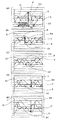
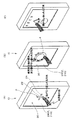
図1は本実施の形態のタッチパネルディスプレイ装置20が組み込まれた電子機器10の斜視図、図2はタッチパネルディスプレイ装置20の分解斜視図、図3はタッチパネルディスプレイ装置20の平面図、図4(A)、(B)はタッチパネルディスプレイ装置20の動作説明図である。
図1に示すように、電子機器10はPDA(Personal Digital Assistant)であり、外装を構成する筐体12を有し、筐体12の内部にタッチパネルディスプレイ装置20と、電源(バッテリー)14(図6)と、CPU50(図6)などの電子部品が実装された基板16などが組み込まれている。
筐体12は、長方形枠状の前板12Aと、前板12Aと対向する後板12Bと、前板12A、後板12Bの四辺を接続する4つの側板12Bとを備えている。
前板12Aには矩形状の開口1202が形成され、開口1202に臨むようにタッチパネルディスプレイ装置20が配設されている。
なお、本明細書において、電子機器10およびタッチパネルディスプレイ装置20の前方とは、電子機器10およびタッチパネルディスプレイ装置20の使用時にユーザに臨む方向をいい、後方とは前方の反対側をいうものとする。
(First embodiment)
Embodiments of the present invention will be described below.
1 is a perspective view of an
As shown in FIG. 1, the
The
A rectangular opening 1202 is formed in the
In this specification, the front of the
図2に示すように、タッチパネルディスプレイ装置20は、ディスプレイパネル21、ホルダ22(支持構造体)、可動パネルユニット24、支持機構26、第1のアクチュエータ28、第2のアクチュエータ30、後述するアクチュエータ駆動制御部などを含んで構成されている。
As shown in FIG. 2, the touch
図2に示すように、ディスプレイパネル21は、画像を表示するための制御信号が供給されることにより表示面2102に画像を表示するものであり、矩形板状(平板形状)を呈している。
本実施の形態では、ディスプレイパネル21は透過型の液晶ディスプレイ装置で構成されている。
ディスプレイパネル21は、液晶層と該液晶層を挟む2枚のガラス基板からなるディスプレイ本体と、ディスプレイ本体の表示面2102と反対側に位置する背面に取着されディスプレイ本体を背面から表示面2102に向けて照明するバックライトとを含んで構成され、バックライトは前記ディスプレイ本体に一体的に取着されている。なお、ディスプレイパネル21は、バックライトが不要な反射型の液晶ディスプレイ装置や有機ELディスプレイ装置であってもよい。
ディスプレイパネル21は表示面2102を開口1202に向けて筐体12に配置され、本実施の形態では、表示面2102を後述する可動パネルユニット24の後面2404に臨ませて筐体12に取着され、表示面2102は可動パネルユニット24とほぼ同形同大の矩形状を呈している。
As shown in FIG. 2, the
In the present embodiment, the
The
The
ホルダ22は、筐体12(図1)の4つの側板12Bの内側に収容可能な大きさの矩形枠状を呈し、ホルダ22は、ディスプレイパネル21よりも開口1202寄りの筐体12の内部に位置するようにその4隅の取り付け片2202が筐体12の内部に取着されている。
ホルダ22は、その中央に矩形状の収容空間23を有している。
図3に示すように、ホルダ22は、収容空間23に臨んで互いに対向する第1側面22A、第2側面22Bと、互いに対向する第3側面22C、第4側面22Dとを備えている。
The
The
As shown in FIG. 3, the
可動パネルユニット24はホルダ22の収容空間23よりも一回り小さい輪郭で構成され、可動パネルユニット24は収容空間23に収容されている。
可動パネルユニット24は、図2に示すように、矩形板状のタッチパネル32を含んで構成されている。
本実施の形態では、タッチパネル32は、例えば2枚の透明なPETフィルムと、その2枚のフィルム間に透明電極フィルムを形成した、いわゆるフィルム−フィルムタイプのタッチパネルで構成されている。なお、タッチパネル24の構造はフィルム−フィルムタイプに限定されるものではなく、従来公知のさまざまな構造が採用可能であり、検出方式も感圧式あるいは静電式など従来公知のさまざまな検出方式が採用可能である。
タッチパネル32は、該タッチパネル32と同形同大か一回り大きな輪郭の矩形板状を呈する基材34の表面に接合され、基材34がディスプレイパネル21側に向くようにタッチパネル32が配置されている。
言い換えると、タッチパネル32がディスプレイパネル21に重なる位置にくるように配置されている。
基材34は、ユーザの指先の圧力に耐えうる剛性を有し、かつ、ディスプレイパネル21に表示される画像を視認できる材料で構成されている。
本実施の形態では、基材34は、透明で硬質なガラス板あるいはアクリルやポリカーボネートなどの合成樹脂板で構成されている。
本実施の形態では、図3に示すように、第1のアクチュエータ28、第2のアクチュエータ30により動かされる可動パネルユニット24の箇所が基材34の4つの側面となっており、それら4つの側面は、互いに対向する第1側面24A、第2側面24Bと、互いに対向する第3側面24C、第4側面24Dである。
また、本実施の形態では、基材34と反対側に位置するタッチパネル24の表面によって可動パネルユニット24の被接触面2402が構成されている。
したがって、ディスプレイパネル21は、被接触面2402と反対に位置するタッチパネル32の面に近接して設けられることになる。
また本実施の形態では、タッチパネル32の被接触面2402と反対に位置する面とディスプレイパネル21の表示面とが離間することになる。
The
As shown in FIG. 2, the
In the present embodiment, the
The
In other words, the
The
In the present embodiment, the
In the present embodiment, as shown in FIG. 3, the
In the present embodiment, the contacted
Therefore, the
In the present embodiment, the surface of the
図2、図3に示すように、本実施の形態では、第1のアクチュエータ28は、ホルダ22の第1側面22Aと可動パネルユニット24の第1側面24Aとの間、および、ホルダ22の第2側面22Bと可動パネルユニット24の第2側面24Bとの間に1つずつ設けられている。
第1のアクチュエータ28として、細長い板状の屈曲変位型圧電アクチュエータを使用することができる。この種の圧電アクチュエータとしては、バイモルフ型圧電アクチュエータや、モノモルフ型圧電アクチュエータが知られており、それらのうちではバイモルフ型の方が、より強力な駆動力を発揮できることから好ましく、また、単層バイモルフ型圧電アクチュエータと積層バイモルフ型圧電アクチュエータとでは、後者の方が低い電圧で駆動できることから、モバイル電子機器に用いるのにより適しているといえる。
そのため、本実施の形態では、第1のアクチュエータ28として積層バイモルフ型圧電アクチュエータを使用している。
図3に示すように、第1側面22Aと第1側面24Aとの間に設けられた第1のアクチュエータ28は、その長手方向両端部がスペーサーブロック36を介して第1側面22Aに連結されており、各スペーサーブロック36と第1アクチュエータ28の各端部との間、並びに、各スペーサーブロック36と第1側面22Aとの間は、両面粘着テープを用いて接着されている。
また、第1側面22Aと第1側面24Aとの間に設けられた第1のアクチュエータ28は、その長手方向中央部がスペーサーブロック38を介して第1側面24Aに連結されており、スペーサーブロック38と第1アクチュエータ28との間、並びに、スペーサーブロック38と第1側面24Aとの間は、両面粘着テープを用いて接着されている。
As shown in FIGS. 2 and 3, in the present embodiment, the
As the
Therefore, in the present embodiment, a laminated bimorph piezoelectric actuator is used as the
As shown in FIG. 3, the
Further, the
第2側面22Bと第2側面24Bとの間に設けられた第1のアクチュエータ28は、その長手方向両端部がスペーサーブロック36を介して第2側面22Bに連結されており、各スペーサーブロック36と第1アクチュエータ28の各端部との間、並びに、各スペーサーブロック36と第2側面22Bとの間は、両面粘着テープを用いて接着されている。
また、第2側面22Bと第2側面24Bとの間に設けられた第1のアクチュエータ28は、その長手方向中央部がスペーサーブロック38を介して第2側面24Bに連結されており、スペーサーブロック38と第1アクチュエータ28との間、並びに、スペーサーブロック38と第2側面24Bとの間は、両面粘着テープを用いて接着されている。
The
The
図3に示すように、本実施の形態では、第2のアクチュエータ30は、ホルダ22の第3側面22Cと可動パネルユニット24の第3側面24Cとの間、および、ホルダ22の第4側面22Dと可動パネルユニット24の第4側面24Dとの間に1つずつ設けられている。
第2のアクチュエータ30としては、第1のアクチュエータ28と同様に細長い板状の屈曲変位型圧電アクチュエータを使用することができ、本実施の形態では、第2のアクチュエータ30として積層バイモルフ型圧電アクチュエータを使用している。
第3側面22Cと第3側面24Cとの間に設けられた第2のアクチュエータ30は、その長手方向両端部が2つのスペーサーブロック36を介して第3側面22Cに連結されており、各スペーサーブロック36と第2のアクチュエータ30の各端部との間、並びに、各スペーサーブロック36と第3側面22Cとの間は、両面粘着テープを用いて接着されている。
また、第3側面22Cと第3側面24Cとの間に設けられた第2のアクチュエータ30は、その長手方向中央部がスペーサーブロック38を介して第3側面24Cに連結されており、スペーサーブロック38と第2のアクチュエータ30との間、並びに、スペーサーブロック38と第3側面24Cとの間は、両面粘着テープを用いて接着されている。
As shown in FIG. 3, in the present embodiment, the
As the
The
In addition, the
第4側面22Cと第4側面24Dとの間に設けられた第2のアクチュエータ30は、その長手方向両端部が2つのスペーサーブロック36を介して第4側面22Dに連結されており、各スペーサーブロック36と第2のアクチュエータ30の各端部との間、並びに、各スペーサーブロック36と第4側面22Dとの間は、両面粘着テープを用いて接着されている。
また、第4側面22Dと第4側面24Dとの間に設けられた第2のアクチュエータ30は、その長手方向中央部がスペーサーブロック38を介して第4側面24Dに連結されており、スペーサーブロック38と第2のアクチュエータ30との間、並びに、スペーサーブロック38と第4側面24Dとの間は、両面粘着テープを用いて接着されている。
The
The
説明の便宜上、可動パネルユニット24の被接触面2402上において、第1側面24Aと第2側面24Bが対向する方向をY方向とし、第3側面24Cと第4側面24Dが対向する方向をX方向とする。
2つの第1のアクチュエータ28に電圧を印加し、図4(A)に示すように、2つの第1のアクチュエータ28にY方向において同一の向きの屈曲変位を発生させると、2つの第1のアクチュエータ28の長手方向中央部がY方向(タッチパネル32の面方向)に変位して、可動パネルユニット24をY方向(タッチパネル32の面方向)に変位させる。
また、2つの第2のアクチュエータ30に電圧を印加し、図4(B)に示すように、2つの第2のアクチュエータ30にX方向において同一の向きの屈曲変位を発生させると、2つの第2のアクチュエータ30の長手方向中央部がX方向(タッチパネル32の面方向)に変位して、可動パネルユニット24をX方向(タッチパネル32の面方向)に変位させる。
可動パネルユニット24の変位の向き及び大きさは、第1、第2のアクチュエータ28、30に印加する電圧の極性及び大きさに対応したものとなる。また、こうして発生する可動パネルユニット24の変位の方向は、この可動パネルユニット24の被接触面2402に平行な平面に沿った方向である。従って、第1、第2のアクチュエータ28、30は、可動パネルユニット24を、その被接触面2402に平行な平面に沿った方向に駆動するものである。
なお、可動パネルユニット24を円滑に振動させるために、2つの第1アクチュエータ28に供給する電圧(後述する駆動信号)を同相とすることで2つの第1アクチュエータ28が屈曲変位する方向が同一とし、かつ、2つの第2アクチュエータ30に供給する電圧(後述する駆動信号)を同相とすることで第2アクチュエータ30が屈曲変位する方向を同一としている。
For convenience of explanation, on the contacted
When a voltage is applied to the two
Further, when a voltage is applied to the two
The direction and magnitude of displacement of the
Note that, in order to smoothly vibrate the
支持機構26は、可動パネルユニット24を被接触面2402と平行な面に沿って変位可能にホルダ22上に支持するものである。
言い換えると、本実施の形態では、支持構造体が筐体12およびホルダ22から構成されており、支持機構26は、可動パネルユニット24を被接触面2402と平行な面に沿って変位可能に前記支持構造体上で支持している。
本実施の形態では、図3に示すように、支持機構26は、第1、第2のアクチュエータ28、30および各スペーサーブロック36、38によって構成されている。
スペーサーブロック36、38は、弾性材料によって構成されており、可動パネルユニット24は、支持機構26によって第1、第2のアクチュエータ28、30の非駆動状態でタッチパネル32が所定位置(初期位置)に復帰するように付勢されている。
スペーサーブロック36、38を構成する弾性材料は、第1、第2のアクチュエータ28、30の駆動力を確実に可動パネルユニット24に伝達し、かつ、可動パネルユニット24を被接触面2402と平行な方向にできるだけ容易に変位させることが望ましい。
すなわち、第1、第2のアクチュエータ28、30のうちの一方のアクチュエータによって可動パネルユニット24が被接触面2402と平行な方向に変位される際には、一方のアクチュエータに設けられたスペーサーブロック36、38を構成する弾性材料は該一方のアクチュエータの駆動力を可動パネルユニット24に確実に伝達するために高い剛性を有することが望ましく、かつ、他方のアクチュエータに設けられたスペーサーブロック36、38を構成する弾性材料は可動パネルユニット24を被接触面2402と平行な方向にできるだけ容易に変位させるために低い剛性を有することが望ましい。
The
In other words, in the present embodiment, the support structure includes the
In the present embodiment, as shown in FIG. 3, the
The spacer blocks 36 and 38 are made of an elastic material. In the
The elastic material constituting the spacer blocks 36 and 38 reliably transmits the driving force of the first and
That is, when the
このような弾性材料としては、超低硬度の高分子ゲル材料から成るものとするとよい。
例えば、北川工業株式会社が「KGゲル(商標)」という製品名で市場に提供している、シート状の超低硬度の高分子ゲル材料は、弾性部材17の材料として特に適したものである。弾性材料として高分子ゲル材料以外の適当な材料としては、例えば、種々のラバー材料、軟質ポリエチレン、それにシリコン樹脂などがある。
図5(A)は第1のアクチュエータ28およびスペーサーブロック36、38の構成を示す斜視図である。
図5(A)に示すように、一方のスペーサーブロック36は、厚さと、厚さよりも大きな寸法の幅と長さを有する板状を呈し、厚さ方向を第1のアクチュエータ28の屈曲変位方向(Y方向)に合致させた状態で厚さ方向の両側が第1のアクチュエータ28とホルダ22とにそれぞれ接着されている。
また、他方のスペーサーブロック38は、厚さと、厚さ方向と直交する幅と長さを有する板状を呈し、厚さ方向を第1のアクチュエータ28の屈曲変位方向(Y方向)に合致させた状態で厚さ方向の両側が第1のアクチュエータ28と可動パネルユニット24とにそれぞれ接着されている。
上述した弾性材料は、厚さ方向に対しては圧縮変位しにくく、厚さ方向と直交する方向(せん断方向)には変位しやすい性状を有していることから、スペーサーブロック36、38は、第1のアクチュエータ28のY方向の駆動力を確実に可動パネルユニット24に伝達でき、かつ、第2のアクチュエータ30によってX方向に動かされる際に可動パネルユニット24を被接触面2402と平行な方向に容易に変位させる上で有利となる。
以上、第1のアクチュエータ28と、第1のアクチュエータ28に接着されるスペーサーブロック36、38について説明したが、第2のアクチュエータ30と、第2のアクチュエータ30に接着されるスペーサーブロック36、38についても上述と同様に構成されている。
したがって、第2のアクチュエータ30に接着されるスペーサーブロック36、38は、第2のアクチュエータ30のX方向の駆動力を確実に可動パネルユニット24に伝達でき、かつ、第1のアクチュエータ28によってY方向に動かされる際に可動パネルユニット24を被接触面2402と平行な方向に容易に変位させる上で有利となる。
Such an elastic material is preferably made of a polymer gel material having an extremely low hardness.
For example, a sheet-like ultra-low hardness polymer gel material provided by Kitagawa Industry Co., Ltd. under the product name “KG Gel (trademark)” is particularly suitable as a material for the elastic member 17. . Examples of suitable materials other than the polymer gel material as the elastic material include various rubber materials, soft polyethylene, and silicon resin.
FIG. 5A is a perspective view showing the configuration of the
As shown in FIG. 5A, one
The
The above-described elastic material is not easily compressed and displaced in the thickness direction, and is easily displaced in the direction perpendicular to the thickness direction (shear direction). Therefore, the spacer blocks 36 and 38 are The driving force in the Y direction of the
The
Therefore, the spacer blocks 36 and 38 bonded to the
図5(B)は、図5(A)のスペーサーブロック36、38の変形例である。
スペーサーブロック36のうち厚さ方向の一方の面に、すなわち、可動パネルユニット24に接合される部分に、厚さ方向に深さを有し幅方向に延在する複数の溝3602を長さ方向に並べて形成し、溝3602の間に複数の壁部3604を形成することで、スペーサーブロック36を厚さ方向と直交する方向(長さ方向)に変形しやすくしたものであり、被接触面2402と平行な方向に容易に変位させる上でより有利となっている。
図5(C)は、図5(B)のスペーサーブロック36のさらなる変形例である。
スペーサーブロック36のうち複数の壁部3604の先端を壁部3606で連結したものであり、壁部3606と可動パネルユニット24との接触面の面積を大きく確保することで、壁部3606と可動パネルユニット24とを接着する際の強度の向上を図ったものである。
FIG. 5B is a modification of the spacer blocks 36 and 38 of FIG.
A plurality of
FIG. 5C is a further modification of the
In the
図2、図3に示すように、上述の支持機構26およびホルダ22を介して、可動パネルユニット24は、ディスプレイパネル21よりも開口1202寄りの箇所で被接触面2402を開口1202に臨ませた状態で介して筐体12に取着されている。
本実施の形態では、被接触面2402の外周全周と、筐体12の前板12Aの開口1202の周囲全周との間に矩形枠状のパッキン40が介在されている。
パッキン40は、可動パネルユニット24の動きを阻止しないように柔軟性を有する材料で形成されており、このような材料としては、軟質のゴム膜や発泡性の軟質素材が採用可能である。
パッキン40は、接着剤あるいは両面粘着テープにより被接触面2402の外周全周と、筐体12の前板12Aの開口1202の周囲全周とに接着され取着されている。
このようなパッキン40によって前板12Aと被接触面2402との間の隙間からの塵埃の侵入の防止が図られている。
As shown in FIGS. 2 and 3, the
In the present embodiment, a rectangular frame packing 40 is interposed between the entire outer periphery of the contacted
The packing 40 is formed of a material having flexibility so as not to prevent the movement of the
The packing 40 is adhered and attached to the entire outer periphery of the contacted
Such packing 40 prevents dust from entering from the gap between the
図6は電子機器10の制御系を示すブロック図である。
図6に示すように、電子機器10は、上述したタッチパネルディスプレイ装置20に加えて、A/D変換器42、D/A変換器44、アンプ46、記憶装置48、CPU50、電源14などを含んで構成されている。
A/D変換器42は、タッチパネル32に接触した指先のタッチパネル32上における位置を示すアナログ信号である検出信号をタッチパネル32から受け取り、デジタル信号に変換し位置データとしてCPU50に供給するものである。
D/A変換器44は、第1、第2のアクチュエータ28、30を駆動するためにCPU50から供給される後述の駆動データをアナログ信号に変換し第1、第2の駆動信号としてアンプ46に供給するものである。
アンプ46は、D/A変換器44から供給された前記第1、第2の駆動信号を増幅して第1、第2のアクチュエータ28、30にそれぞれ供給することで第1、第2のアクチュエータ28、30を振動させるものである。
なお、図6では、図面の簡略化を図るために、D/A変換器44およびアンプ46をそれぞれ単一のものとして描いているが、D/A変換器44およびアンプ46はアクチュエータごとに設けられている。
記憶装置48は、CPU50が実行するための制御プログラム、前記駆動データ、ディスプレイパネル21に画像を表示するための画像データなどが格納されている。
CPU50は、A/D変換器42から供給される前記位置データに基づいて前記駆動データを記憶装置48から読み出してD/A変換器44に供給し、また、ディスプレイパネル21に記憶装置48から読み出した前記画像データを供給するものである。
また、A/D変換器42、D/A変換器44、アンプ46、記憶装置48、CPU50は、図1に示す基板16に実装されている。
電源14は、CPU50を含む各部に動作用の電源を供給するものである。
本実施の形態では、D/A変換器44、アンプ46、記憶装置48、CPU50によって、第1、第2のアクチュエータ28、30の駆動を制御するアクチュエータ駆動制御部が構成されている。
FIG. 6 is a block diagram showing a control system of the
As shown in FIG. 6, the
The A /
The D /
The
In FIG. 6, in order to simplify the drawing, the D /
The
The
Further, the A /
The
In the present embodiment, the D /
次に、本発明の要旨であるタッチパネルディスプレイ装置20の動作原理について説明する。
図7(A)乃至(E)は第1のアクチュエータ28に供給する第1の駆動信号Sdと、第1のアクチュエータ28によって振動される可動パネルユニット24の速度Vと、可動パネルユニット24の加速度Aとの関係を示す説明図であり、横軸は時間、縦軸は任意単位である。
なお、以下では第1のアクチュエータ28の動作について説明するが、第2のアクチュエータ30についても動作は同様である。
アクチュエータが圧電アクチュエータ(ピエゾアクチュエータ)である場合、アクチュエータの変位量は、第1の駆動信号Sdの電圧値に比例したものとなり、したがって、第1の駆動信号Sdの変化と、アクチュエータによる可動パネルユニット24の変位量とが対応することになる。
Next, the operation principle of the touch
7A to 7E show the first drive signal Sd supplied to the
Although the operation of the
When the actuator is a piezoelectric actuator (piezo actuator), the displacement amount of the actuator is proportional to the voltage value of the first drive signal Sd. Therefore, the change of the first drive signal Sd and the movable panel unit by the
図7(C)では、第1の駆動信号Sdが振幅が一定の三角波状の波形が一定周期で繰り返される繰り返し波形であり、電圧値が最小値から最大値に変化するのに要する第1の期間T1と、電圧値が最大値から最小値に変化するのに要する第2の期間T2とが同一の時間であり、言い換えると、第1の駆動信号Sdが対称な形状の波形を呈している。
ここで、Y方向の一方を第1方向とし、Y方向の他方(反対方向)を第2方向とすると、第1の期間T1は可動パネルユニット24が第1方向に動く期間であり、第2の期間T2は可動パネルユニット24が第2方向に動く期間である。
なお、速度Vは、第1の駆動信号Sdを微分した波形形状であり、台形の波形が一定周期で繰り返される繰り返し波形となる。
また、加速度Aは、速度Vを微分した波形形状となる。
この場合、第1の駆動信号Sdで示されるように、可動パネルユニット24は第1のアクチュエータ28によってY方向に沿って往復移動されるが、加速度Aの波形を見て明らかなように、第1方向に移動する際の加速度A1と、第2方向に移動する際の加速度A2とでは波形形状が対称となっている。
この際、第1方向の加速度A1および第2方向の加速度A2は、何れも被接触面2402に触れている指先が静止摩擦力によって被接触面2402に追従して動く程度の値に留まっている。
したがって、この状態で可動パネルユニット24の被接触面2402上に指先を触れている場合には、指先は被接触面2402との間の静止摩擦力によって被接触面2402に追従してY方向に沿って往復振動するのみであり、指先がY方向に沿って移動する現象は生じない。
In FIG. 7C, the first drive signal Sd is a repetitive waveform in which a triangular waveform having a constant amplitude is repeated at a constant cycle, and the first drive signal Sd required for the voltage value to change from the minimum value to the maximum value. The period T1 and the second period T2 required for the voltage value to change from the maximum value to the minimum value are the same time. In other words, the first drive signal Sd has a symmetrical waveform. .
Here, if one of the Y directions is the first direction and the other of the Y directions (opposite direction) is the second direction, the first period T1 is a period during which the
The speed V has a waveform shape obtained by differentiating the first drive signal Sd, and is a repetitive waveform in which a trapezoidal waveform is repeated at a constant period.
The acceleration A has a waveform shape obtained by differentiating the velocity V.
In this case, as indicated by the first drive signal Sd, the
At this time, the acceleration A1 in the first direction and the acceleration A2 in the second direction both remain at values such that the fingertip touching the contacted
Therefore, when the fingertip is touching the contacted
図7(B)では、第1の駆動信号Sdの波形形状が図7(C)に比較して変化しており、第1の期間T1に対して第2の期間T2が短くなっており、第1の駆動信号Sdが非対称な形状の波形形状を呈し、言い換えると、変則的なランプ波あるいは三角波の形状を呈している。
すなわち、可動パネルユニット24が第1方向に動く期間T1における可動パネルユニット24の加速度の時間的変化を示す波形形状を第1の波形形状とし、可動パネルユニット24が第2方向に動く期間における可動パネルユニット24の加速度の時間的変化を示す波形形状を第2の波形形状としたときに、前記アクチュエータ駆動制御部は、駆動信号として、第1の波形形状と、第2の波形形状とが非対称となるように第1のアクチュエータ28を駆動する非対称駆動信号を生成している。
この場合、第1の駆動信号Sdで示されるように、可動パネルユニット24は第1のアクチュエータ28によってY方向に沿って往復移動されるが、加速度Aの波形を見て明らかなように、第1方向の加速度A1と、第2方向の加速度A2とでは波形形状が非対称となっている。
この際、第1方向の加速度A1は、被接触面2402に触れている指先が静止摩擦力によって被接触面2402に追従して動く程度の値に留まっているが、第2方向の加速度A2は、第1方向の加速度よりも大きな値となり、これにより被接触面2402に触れている指先が慣性により被接触面2402上で滑り、指先が被接触面2402上に留まるように設定されている。
したがって、この状態で可動パネルユニット24の被接触面2402上に指先を触れている場合には、第1の期間T1で指先は被接触面2402との間の静止摩擦力によって被接触面2402に追従してY方向に沿って動かされるが、第2の期間T2で被接触面2402が第1の期間T1よりも高速に動き慣性により指先と被接触面2402との間が滑ると、指先は被接触面2402上に留まり移動しない。したがって、指先は第1方向に移動することになる。
なお、図7(A)、(B)、(D)、(E)において矢印Fの向きは指先の移動方向を示し、矢印Fの長さは単位時間当たりの指先の移動量(被接触面2402から指先に付与される力(指先に作用する力)の大きさ)を示す。
In FIG. 7B, the waveform shape of the first drive signal Sd is changed as compared with FIG. 7C, and the second period T2 is shorter than the first period T1, The first drive signal Sd has an asymmetric waveform shape, in other words, an irregular ramp wave or triangular wave shape.
That is, the waveform shape showing the temporal change in the acceleration of the
In this case, as indicated by the first drive signal Sd, the
At this time, the acceleration A1 in the first direction remains at a value such that the fingertip touching the contacted
Accordingly, when the fingertip is touching the contacted
7A, 7B, 7D, and 7E, the direction of the arrow F indicates the direction of movement of the fingertip, and the length of the arrow F indicates the amount of movement of the fingertip per unit time (contacted surface). The magnitude of the force (force acting on the fingertip) applied from 2402 to the fingertip).
図7(A)では、第1の駆動信号Sdの波形形状が図7(B)に比較して変化しており、第1の期間T1に対して第2の期間T2がより一層短くなっており、第1の駆動信号Sdが非対称な形状の波形を呈している。すなわち、前記アクチュエータ駆動制御部は、非対称駆動信号を生成している。
この場合には、加速度Aの波形を見て明らかなように、第1方向の加速度A1と、第2方向の加速度A2とでは波形形状が図7(B)に比較してより顕著に非対称となっている。
この際、図7(B)の場合と同様に、第1方向の加速度A1は、被接触面2402に触れている指先が静止摩擦力によって被接触面2402に追従して動く程度の値に留まっているが、第2方向の加速度A2は、第1方向の加速度A1よりも大きな値となり、これにより被接触面2402に触れている指先が慣性により被接触面2402上で滑り指先が被接触面2402上に留まるように設定されている。
この状態で可動パネルユニット24の被接触面2402上に指先を触れている場合には、第1の期間T1で指先は被接触面2402との間の静止摩擦力によって被接触面2402に追従してY方向に沿って動かされるが、第1の期間T1がより長くなっているため、指先が動かされる距離がより長くなっている。そして、第2の期間T2では、被接触面2402が第1の期間T1よりも高速に動き慣性により指先と被接触面2402との間が滑り、指先は被接触面2402上に留まり移動しない。したがって、指先は第1方向に移動するが、その移動量および指先に付与される力は、矢印Fに示すように、図7(C)に比較してより大きなものとなる。
In FIG. 7A, the waveform shape of the first drive signal Sd is changed as compared with FIG. 7B, and the second period T2 becomes even shorter than the first period T1. Thus, the first drive signal Sd has an asymmetrical waveform. That is, the actuator drive control unit generates an asymmetric drive signal.
In this case, as apparent from the waveform of the acceleration A, the waveform shape between the acceleration A1 in the first direction and the acceleration A2 in the second direction is more significantly asymmetric than that in FIG. 7B. It has become.
At this time, as in the case of FIG. 7B, the acceleration A1 in the first direction remains at such a value that the fingertip touching the contacted
In this state, when the fingertip touches the contacted
図7(D)、(E)は、第1の期間T1と第2の期間T2の大小関係が図7(B)、(A)の場合と反対になったものである。
すなわち、図7(D)は、第1の駆動信号Sdの波形形状が図7(C)に比較して変化しており、第2の期間T2に対して第1の期間T1が短くなっており、言い換えると、第1の駆動信号Sdが非対称な形状の波形形状を呈し、言い換えると、変則的なランプ波あるいは三角波の形状を呈している。すなわち、前記アクチュエータ駆動制御部は、非対称駆動信号を生成している。
この場合も、第1方向の加速度A1と、第2方向の加速度A2とでは波形形状が非対称となっている。
この際、第2方向の加速度A2は、被接触面2402に触れている指先が静止摩擦力によって被接触面2402に追従して動く程度の値に留まっているが、第1方向の加速度A1は、第2方向の加速度A2よりも大きな値となり、これにより被接触面2402に触れている指先が慣性により被接触面2402上で滑り指先が被接触面2402上に留まるように設定されている。
この状態で可動パネルユニット24の被接触面2402上に指先を触れている場合には、第2の期間T2で指先は被接触面2402との間の静止摩擦力によって被接触面2402に追従してY方向に沿って動かされるが、第1の期間T1で被接触面2402が第2の期間T2よりも高速に動き慣性により指先と被接触面2402との間が滑ると、指先は被セ接触面2402に留まり移動しない。したがって、矢印Fに示すように、指先は第2方向に沿って移動することになる。
In FIGS. 7D and 7E, the magnitude relationship between the first period T1 and the second period T2 is opposite to that in FIGS. 7B and 7A.
That is, in FIG. 7D, the waveform shape of the first drive signal Sd is changed as compared with FIG. 7C, and the first period T1 is shorter than the second period T2. In other words, the first drive signal Sd has an asymmetrical waveform shape, in other words, an irregular ramp wave or triangular wave shape. That is, the actuator drive control unit generates an asymmetric drive signal.
Also in this case, the waveform shape is asymmetric between the acceleration A1 in the first direction and the acceleration A2 in the second direction.
At this time, the acceleration A2 in the second direction remains at such a value that the fingertip touching the contacted
In this state, when the fingertip touches the contacted
図7(E)では、第1の駆動信号Sdの波形形状が図7(D)に比較して変化しており、第2の期間T2に対して第1の期間T1がより一層短くなっており、第1の駆動信号Sdが非対称な形状の波形を呈している。すなわち、前記アクチュエータ駆動制御部は、非対称駆動信号を生成している。
この場合には、加速度Aの波形を見て明らかなように、第1方向の加速度A1と、第2方向の加速度A2とでは波形形状が図7(D)に比較してより顕著に非対称となっている。
この際、図7(D)の場合と同様に、第2方向の加速度A2は、被接触面2402に触れている指先が静止摩擦力によって被接触面2402に追従して動く程度の値に留まっているが、第1方向の加速度A1は、第2方向の加速度A2よりも大きな値となり、これにより被接触面2402に触れている指先が慣性により被接触面2402上で滑り、指先が被接触面2402上に留まるように設定されている。
この状態で可動パネルユニット24の被接触面2402上に指先を触れている場合には、第2の期間T2で指先は被接触面2402との間の静止摩擦力によって被接触面2402に追従してY方向に沿って動かされるが、第2の期間T2がより長くなっているため、指先が動かされる距離がより長くなっている。そして、第1の期間T1では、被接触面2402が第2の期間T2よりも高速に動き慣性により指先と被接触面2402との間が滑り、指先は被接触面2402上に留まり移動しない。したがって、指先は第2方向に沿って移動するが、その移動量および指先に付与される力は、矢印Fに示すように、図7(D)に比較してより大きなものとなる。
In FIG. 7E, the waveform shape of the first drive signal Sd is changed as compared with FIG. 7D, and the first period T1 becomes even shorter than the second period T2. Thus, the first drive signal Sd has an asymmetrical waveform. That is, the actuator drive control unit generates an asymmetric drive signal.
In this case, as apparent from the waveform of the acceleration A, the waveform shape between the acceleration A1 in the first direction and the acceleration A2 in the second direction is more significantly asymmetric than that in FIG. It has become.
At this time, as in the case of FIG. 7D, the acceleration A2 in the second direction remains at such a value that the fingertip touching the contacted
In this state, when the fingertip touches the contacted
また、図7(A)乃至(E)で説明した動作を言い換えると、加速度が小さく被接触面2402に触っている指先の静止摩擦が作用している場合には、指先が被接触面2402の移動に追従して移動し、加速度が大きく被接触面2402に触っている指先が慣性により滑る場合には、指先が被接触面2402の移動に追従せず被接触面2402上に留まることになる。
加速度を大きくするには(指先を被接触面2402に沿って動かす力を大きくするには)、前述したように、第1の駆動信号Sdをより顕著に非対称な形状にすればよく、言い換えると、第1の期間T1と第2の期間T2との時間差を大きくすればよい。
また、加速度を大きくするには、可動パネルユニット24の単位時間当たりの移動量を増大すればよく、したがって、第1の駆動信号Sdの振幅を大きくしてもよい。
また、加速度を大きくするには、可動パネルユニット24をより高速に動かせばよく、したがって、第1の駆動信号Sdの周波数を高くしてもよい。
7A to 7E, in other words, when the friction of the fingertip touching the contacted
In order to increase the acceleration (in order to increase the force for moving the fingertip along the contacted surface 2402), as described above, the first drive signal Sd may be made to have a more significantly asymmetric shape, in other words, The time difference between the first period T1 and the second period T2 may be increased.
In order to increase the acceleration, it is only necessary to increase the amount of movement of the
In order to increase the acceleration, the
上述のような動作を第1のアクチュエータ28で行えば、被接触面2402上に触れた指先をY方向に沿って動かすことができる。
そして、上述のような動作を第2のアクチュエータ30で行えば、被接触面2402上に触れた指先をX方向に沿って動かすことができる。
言い換えると、第1のアクチュエータ28は、第1の駆動信号が供給されることで可動パネルユニット24を被接触面2402に平行な平面に沿ってX方向、すなわち第1の直線上を往復振動させるものである。
第2のアクチュエータ30は、第2の駆動信号が供給されることで可動パネルユニット24を被接触面2402に平行な平面に沿ってY方向、すなわち、第1の直線と交差する(本実施の形態では直交する)第2の直線上を往復振動させるものである。
X方向に沿った一方向を第1方向、その反対方向を第2方向とし、Y方向に沿った一方向を第3方向、その反対方向を第4方向とする。
可動パネルユニット24が第1方向に動く期間における可動パネルユニット24の加速度の時間的変化を示す波形形状を第1の波形形状とし、可動パネルユニット24が第2方向に動く期間における可動パネルユニット24の加速度の時間的変化を示す波形形状を第2の波形形状とする。
可動パネルユニット24が第3方向に動く期間における可動パネルユニット24の加速度の時間的変化を示す波形形状を第3の波形形状とし、可動パネルユニット24が第4方向に動く期間における可動パネルユニット24の加速度の時間的変化を示す波形形状を第4の波形形状とする。
前記アクチュエータ駆動制御部は、第1の駆動信号として、第1の波形形状と、第2の波形形状とが非対称となるようにアクチュエータを駆動する第1の非対称駆動信号を生成し、かつ、第2の駆動信号として、第3の波形形状と、第4の波形形状とが非対称となるようにアクチュエータを駆動する第2の非対称駆動信号を生成する。
このような構成とすることで、被接触面2402上に触れた指先をY方向とX方向との双方に沿って動かすことができ、Y方向とX方向との双方の移動量を変化させることにより、被接触面2402に触れた指先に対して被接触面2402に沿った任意の方向の力を付与することで指先を任意の方向に動かすことができる。
なお、第1の駆動信号および第2の駆動信号の周波数をどのように設定するかは任意であるが、第1の駆動信号および第2の駆動信号の周波数を同一とすれば、アクチュエータ駆動制御部の構成を簡素化する上で有利となる。
If the
When the above-described operation is performed by the
In other words, the
When the
One direction along the X direction is a first direction, the opposite direction is a second direction, one direction along the Y direction is a third direction, and the opposite direction is a fourth direction.
The waveform shape showing the temporal change in the acceleration of the
The waveform shape showing the temporal change in the acceleration of the
The actuator drive control unit generates, as a first drive signal, a first asymmetric drive signal for driving the actuator so that the first waveform shape and the second waveform shape are asymmetric, As the second drive signal, a second asymmetric drive signal for driving the actuator is generated so that the third waveform shape and the fourth waveform shape are asymmetric.
With such a configuration, the fingertip touching the contacted
Note that how to set the frequencies of the first drive signal and the second drive signal is arbitrary, but if the frequencies of the first drive signal and the second drive signal are the same, actuator drive control is performed. This is advantageous in simplifying the configuration of the part.
図8(A)、(B)、(C)は電子機器10に組み込まれたタッチパネルディスプレイ装置20の動作説明図である。
図6に示すように、CPU50は、記憶装置48に格納されている画像データに基づいてディスプレイパネル21の表示面に指先を触れるべき箇所であることを示すマーク、すなわち、図8(A)に示す十字キー2や、図8(B)に示すダイヤル4を表示させる機能を有している。
なお、十字キー2は、X方向に沿って互いに反対方向を向く2つの方向キー2Aと、Y方向に沿って互いに反対方向を向く2つの方向キー2Aとの4つの方向キー2Aを含んで構成されている。言い換えると、各方向キー2Aは特定方向を向いた形状を含んで構成されている。
そして、4つの方向キー2Aは、それらの何れか1つの方向キー2Aが択一的に指先で触れられて操作されるものである。
また、ダイヤル4は、円環状の形状を呈し、その円周方向に沿って正方向あるいは逆方向に指先がなぞるように触れられることで、あたかもダイヤル4を正方向あるいは逆方向に回転操作しているように操作されるものである。
また、記憶装置48には、ディスプレイパネル21に表示された十字キー2(各方向キー2A)やダイヤル4の箇所を、タッチパネル32のX方向およびY方向における座標位置で示した位置データが格納され、マッピングメモリが構成されている。
したがって、CPU50は、タッチパネル32からA/D変換器42を介して供給される検出信号に基づいて、前記マッピングメモリを検索することにより、各方向キー2Aやダイヤル4に対応する箇所のタッチパネル32に指先が触れたか否かを判別するように構成されている。
また、記憶装置48には、各方向キー2Aやダイヤル4の位置データと、第1、第2の駆動信号の波形形状を決定する波形データとが関連付けて格納されている。言い換えると、前記マッピングメモリに、第1、第2の駆動信号の波形形状を決定する波形データが関連付けられていることになる。
すなわち、各方向キー2Aやダイヤル4の箇所に指先が触った際に、指先に与える力の方向や大きさが予め定められており、そのような力を被接触面2402から指先に与えるために必要な可動パネルユニット24の振動方向や振動の大きさを決定する第1、第2の駆動信号の波形データが各方向キー2Aやダイヤル4の位置データと関連付けて記憶装置48に格納されているのである。
8A, 8 </ b> B, and 8 </ b> C are operation explanatory diagrams of the touch
As shown in FIG. 6, the
The
The four
The
Further, the
Accordingly, the
The
That is, the direction and magnitude of the force applied to the fingertip when the fingertip touches each directional key 2A or
次に、図9のフローチャートを参照して電子機器10の動作について説明する。
なお、CPU50は、現在指先が触れているタッチパネル32の位置Ptを示す位置データ(座標値)Xt、Ytと、その直前において指先が触れていたタッチパネル32の位置Pt−1を示す位置データ(座標値)Xt−1、Yt−1とを変数として保持するように構成されているものとする。
まず、電子機器10の電源が投入されると、CPU50は制御動作をスタートさせ、上述した4つの位置データXt、Yt、Xt−1、Yt−1の全てを初期化してゼロクリアする(ステップS10)。
次に、タッチパネル32に対して指先が触れているか否かを判別し(ステップS12)、指先が触れていなければ、4つの位置データXt、Yt、Xt−1、Yt−1の全てを初期化してゼロクリアし(ステップS40)、第1、第2のアクチュエータ28、30に対する第1、第2の駆動信号の供給を行わずアクチュエータを動作することなく(ステップS42)、ステップS12に戻る。
タッチパネル32からの検出信号により指先がタッチパネル32に触れていることが検出されると(ステップS12で「Y」)、前記検出信号に基づいて座標位置を計測し現在指先が触れている位置データXt、Ytを求める(ステップS14)。
次いで、求められた現在の位置データXt、Ytと、直前における位置データXt−1、Yt−1との差分ΔX=Xt−Xt−1、ΔY=Yt−Yt−1を計算により求める(ステップS16)。
これら差分ΔX、ΔYは、直前の指先の位置に対して現在の指先の位置が被接触面2402上においてどの方向に対してどの距離だけ変位したかを示すデータである。
次に、現在の位置データXt、Ytに基づいて記憶装置48の前記マッピングメモリを検索することにより、指先が各方向キー2Aの箇所(指先位置対応エリア)に触れているか否かが判定される(ステップS20)。
指先が各方向キー2A2に触れていると判定されたならば、記憶装置48の前記マッピングメモリに関連付けられている第1、第2の駆動信号の波形データを読み出し、該波形データをD/A変換器44、アンプ46を介して第1、第2のアクチュエータ28、30に供給することで可動パネルユニット24を振動させる(ステップS22)。
例えば、指先が触れている各方向キー2Aの方向の力を指先に付与するに足る第1、第2の駆動信号が第1、第2のアクチュエータ28、30に供給されることで可動パネルユニット24が振動され、指先が触れている方向キー2Aの方向の力が指先に付与されることになる。
これにより、ユーザは方向キー2Aのうちどの方向キー2Aを触れているかを確実に認識することができる。
ステップS22が終了したならば、現在の位置データXt、Ytを、直前における位置データXt−1、Yt−1として更新し(ステップS38)、ステップS12に戻る。
Next, the operation of the
The
First, when the power of the
Next, it is determined whether or not the fingertip is touching the touch panel 32 (step S12). If the fingertip is not touching, the four position data Xt , Yt , Xt-1 , and Yt-1 are determined. All are initialized and cleared to zero (step S40), the first and second drive signals are not supplied to the first and
When it is detected by the detection signal from the
Next, the difference ΔX = X t −X t−1 , ΔY = Y t −Y t− between the obtained current position data X t and Y t and the previous position data X t−1 and Y t−1. 1 is obtained by calculation (step S16).
These differences ΔX and ΔY are data indicating the distance in which direction the current fingertip position is displaced on the contacted
Next, by searching the mapping memory of the
If it is determined that the fingertip is touching each direction key 2A2, the waveform data of the first and second drive signals associated with the mapping memory of the
For example, the movable panel unit is supplied by supplying first and second drive signals to the first and
Thereby, the user can surely recognize which directional key 2A of the
If step S22 is completed, the current position data X t, the Y t, and updated as the
また、ステップS20が「N」であれば、次いで、指先がダイヤル4の箇所(指先動き対応エリア)に触れられていると判定される(ステップS24)。
指先がダイヤル4の箇所に触れられていると判定されたならば、ステップS16で算出された差分ΔX、ΔYのそれぞれが、規定値を上回るか否かが判定される(ステップS26)。
すなわち、被接触面2402を触れる指先がダイヤル4の円周方向に沿って動かされているか否かが判定される。
ステップS26で規定値を上回ると判定され、したがって、指先がダイヤル4の円周方向に沿って動かされていると判定されたならば、記憶装置48の前記マッピングメモリに関連付けられている第1、第2の駆動信号の波形データを読み出し、該波形データをD/A変換器44、アンプ46を介して第1、第2のアクチュエータ28、30に供給することで可動パネルユニット24を振動させる(ステップS28)。
例えば、指先がダイヤル4の円周方向に沿って動く方向に、言い換えると、指先の動きベクトル方向の力を指先に付与するに足る第1、第2の駆動信号が第1、第2のアクチュエータ28、30に供給されることで可動パネルユニット24が振動され指先にダイヤル4の円周方向に沿った力が付与されることになる。
これにより、ユーザは、指先を動かしている方向と同じ方向でダイヤル4の円周方向に沿った力を受けるため、ユーザはダイヤル4を回転操作していることを確実に認識することができる。
ステップS28が終了したならば、現在の位置データXt、Ytを、直前における位置データXt−1、Yt−1として更新し(ステップS38)、ステップS12に戻る。
また、ステップS26で「N」、すなわち、ダイヤル4に沿って動かされていないと判定された場合には、改めて、被接触面2402を触れる指先がダイヤル4の箇所(指先位置対応エリア)に位置しているか否かを判定し(ステップS32)、指先がダイヤル4の箇所に位置していると判定されたならば、記憶装置48の前記マッピングメモリに関連付けられている第1、第2の駆動信号の波形データを読み出し、該波形データをD/A変換器44、アンプ46を介して第1、第2のアクチュエータ28、30に供給することで可動パネルユニット24を振動させる(ステップS34)。
例えば、指先がダイヤル4の円周方向に沿った方向の力を指先に付与するに足る第1、第2の駆動信号が第1、第2のアクチュエータ28、30に供給されることで可動パネルユニット24が振動され指先が力を受けることになる。
これにより、ユーザは指先がダイヤル4の円周方向に沿った力を付与されるため、ダイヤル4を円滑に回転操作することができる。
If step S20 is “N”, it is then determined that the fingertip is touching the location of the dial 4 (fingertip movement corresponding area) (step S24).
If it is determined that the fingertip is touching the part of the
That is, it is determined whether or not the fingertip touching the contacted
If it is determined in step S26 that the prescribed value is exceeded, and therefore it is determined that the fingertip is moved along the circumferential direction of the
For example, the first and second drive signals that are sufficient to apply a force in the direction of the motion vector of the fingertip to the fingertip in the direction in which the fingertip moves along the circumferential direction of the
Thereby, since the user receives the force along the circumferential direction of the
If step S28 is completed, the current position data X t, the Y t, and updated as the
If it is determined in step S26 that “N”, that is, it is not moved along the
For example, the first and second drive signals that are sufficient for the fingertip to apply a force in the direction along the circumferential direction of the
Thus, the user can smoothly rotate the
また、ステップS32で指先がダイヤル4の箇所に位置していないと判定された場合、および、ステップS20、S24で指先が触れている被接触面2402の箇所が各方向キー2A、ダイヤル4と異なる箇所であると判定された場合には、CPU50は第1、第2のアクチュエータ28、30に対する第1、第2の駆動信号の供給を行わずアクチュエータを動作させない(ステップS30)。
そして、十字キー2あるいはダイヤル4に対する一連の操作が終了し終了コマンドがCPU50で発行されたか否かを判定し(ステップS36)、終了コマンドが供給されなければ、現在の位置データXt、Ytを、直前における位置データXt−1、Yt−1として更新し(ステップS38)、ステップS12に戻る。
また、終了コマンドが発行されたならば、動作を終了する。
Further, when it is determined in step S32 that the fingertip is not located at the location of the
Then, it is determined whether a series of operations on the
If an end command is issued, the operation is terminated.
なお、図8(A)、(B)の説明では、十字キー2およびダイヤル4を用いた場合について説明したが、第1、第2の駆動信号を設定することにより、図8(C)に示すように、円形や三角形、四角形、多角形などの種々の形状に沿った方向の力を指先に付与したり、あるいは、文字や記号などの形状に沿った方向の力を指先に付与することも可能であることは無論である。
In the description of FIGS. 8A and 8B, the case where the
また、ダイヤル4を回転操作する際に、その回転操作と同じ方向の力を可動パネルユニット24を振動させることにより指先に付与する場合について説明したが、回転操作と反対方向の力を指先に付与するように可動パネルユニット24を振動させてもよい。
この場合には、例えば、ダイヤル4の回転操作量が所定の基準量未満である場合には、回転操作方向と同じ方向の力が指先に付与されるように可動パネルユニット24を振動させ、一方、ダイヤル4の回転操作量が所定の基準量を超過した場合に、回転操作と反対方向の力を指先に付与するように可動パネルユニット24を振動させれば、ダイヤル4の回転操作量が所定の基準量を超過したか否かをユーザに認識させることができ、言い換えると、操作時に警告を与えることができる。
Moreover, when rotating the
In this case, for example, when the rotation operation amount of the
また、図8(A)に示すように、ディスプレイパネル21に、上下左右に対応付けられた4つの方向キー2A(カーソル)と、4つの方向キー2Aの中央に形成されたエンターキー2B(エンターカーソル)が表示された状態で、ユーザが右方向の方向キー2Aを指先で触れたときには右方向に指先が引っ張られ、上方向の方向キー2Aを指先で触れたときには上方向に指先が引っ張られ、エンターキー2Bを押したときには単に振動が指先に伝わるような使用が可能である。
例えば、電子機器10が音声データを再生して音声を出力するオーディオ機器であった場合には、図8(B)に示すように、ユーザが指先でダイヤル4をなぞるように触ると、再生される音声出力の音量が増減したり、再生される音声データの早送りや巻き戻しを行うような制御を行うことが可能である。
このとき、指先のなぞる方向またはその正反対方向に指先を引っ張るように可動パネルユニット24の振動を制御することで、ユーザは、直感的に「回転操作が電子機器10に認識されている」ということを知覚できる。
ここで、指先でなぞる方向に引っ張る方向に可動パネルユニット24の振動を制御すれば、ユーザは非常に軽いダイヤル4を回しているような操作感を与えることになる。
また、指先でなぞる方向と逆方向に指先を引っ張るように可動パネルユニット24の振動を制御すれば、重いダイヤル4を回しているような操作感を与えることになる。
そこで操作感の「軽い」あるいは「重い」に、電子機器10特有の意味を持たせると、ユーザは機器から発せられる情報を上記操作に対する触覚のみから感覚的に整合する形態で認識することができる。
例えば、操作感が軽い間はお勧めのボリューム範囲内であるという意味を持たせ、操作感が重くなると、お勧め範囲外である、あるいは、大音量限界を超えている、あるいは、音歪みが生じ始める音量である、あるいは、音漏れし始める音量であるといった意味を持たせることにより、操作性を向上させる上で有利な情報をユーザに認識させることができる。
さらに、例えば図8(C)のように、簡単な文字や数字、記号であれば、指先をその書き順に引っ張ることで、ユーザが画面を見なくとも文字情報を認識させることも可能となる。
ここで、単純化された記号に連想しやすい意味を持たせることで(例えば○はOKで、△はNGなど)、触覚に対して確認・認識しやすい形態で意味を持った出力を行うことが可能となる。
Further, as shown in FIG. 8A, the
For example, if the
At this time, by controlling the vibration of the
Here, if the vibration of the
Further, if the vibration of the
Therefore, if the operation feeling “light” or “heavy” has a meaning specific to the
For example, if the operation feeling is light, it means that it is within the recommended volume range, and if the operation feeling becomes heavy, it is out of the recommended range, or the volume limit is exceeded, or sound distortion occurs. By giving the meaning that the sound volume starts or the sound volume starts to leak, it is possible to make the user recognize information that is advantageous in improving operability.
Further, for example, as shown in FIG. 8C, if the character, number, or symbol is simple, the user can recognize the character information without looking at the screen by pulling the fingertip in the writing order.
Here, by giving meanings that are easily associated with simplified symbols (for example, ○ is OK and △ is NG), meaningful output in a form that is easy to confirm and recognize touch is provided. Is possible.
以上説明したように、本実施の形態によれば、前記アクチュエータ駆動制御部から第1、第2のアクチュエータ28、30に非対称駆動信号を供給することで、可動パネルユニット24を振動させることにより、被接触面2402上に接触している指先に被接触面2402に沿った方向の力を与えることができるため、ユーザの指先に異なる振動パターンの触覚を与えることで多くの情報量をユーザに伝えることができ、操作性の向上を図る上で有利となる。
As described above, according to the present embodiment, by supplying an asymmetric drive signal to the first and
なお、第1の実施の形態では、可動パネルユニット24が筐体12およびホルダ22からなる支持構造体上で支持機構26を介して変位可能に支持され、ディスプレイパネル21が支持構造体上に固定され、タッチパネル34が被接触面2402と反対に位置するタッチパネル32の面に近接して設けられている場合について説明したが、タッチパネル34の被接触面2402と反対に位置する面とディスプレイパネル21の表示面とが一体に結合されて可動パネルユニット24が構成されている場合にも本発明は無論適用可能である。
また、本実施の形態では、第1、第2のアクチュエータ28、30が可動パネルユニット24の側面とホルダ22の側面との間に配置された場合について説明したが、要は、第1、第2のアクチュエータ28、30によって可動パネルユニット24を被接触面2402と平行な平面に沿って振動させることができればよいのであり、第1、第2のアクチュエータ28、30の配置箇所は任意である。
また、本実施の形態では、第1、第2のアクチュエータ28、30をそれぞれ2つずつ設けた場合について説明したが、第1、第2のアクチュエータ28、30の数は任意である。
また、本実施の形態では、支持機構26が、第1、第2のアクチュエータ28、30および各スペーサーブロック36、38によって構成されている場合について説明したが、要は支持機構26によって可動パネルユニット24を被接触面2402に平行な平面に沿って変位可能に支持できればよい。
例えば、可動パネルユニット24をその厚さ方向で挟持しつつ可動パネルユニット24を被接触面2402に平行な平面に沿ってスライド移動可能に、かつ、前記厚さ方向には移動不能に支持する案内部材によって支持機構26を構成してもよく、支持機構26の構成として従来公知のさまざまな支持構造が採用可能である。
また、本実施の形態では、第1、第2のアクチュエータ28、30を用いて可動パネルユニット24を互いに交差する第1、第2の直線に沿って振動させる場合について説明したが、例えば、第1のアクチュエータ28のみを設け、可動パネルユニット24を第1の直線に沿ってのみ振動させるようにしてもよい。
この場合には、ディスプレイパネル21の表示面に指先を触れるべき箇所であることを示すマークを表示し、マークを第1方向または第2の方向の少なくとも一方の方向に合致した方向を向いた形状を含んで構成すればよい。
In the first embodiment, the
Further, in the present embodiment, the case where the first and
In the present embodiment, the case where two each of the first and
In the present embodiment, the case where the
For example, a guide that supports the
In the present embodiment, the case where the
In this case, a mark indicating that the fingertip is to be touched on the display surface of the
(第2の実施の形態)
次に第2の実施の形態について説明する。
第2の実施の形態は、アクチュエータに供給する非対称駆動信号の波形形状が第1の実施の形態と異なっており、その他の点は第1の実施の形態と同様である。
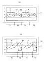
図10は(A)、(B)は第2の実施の形態において第1のアクチュエータ28に供給する第1の駆動信号Sdと、第1のアクチュエータ28によって振動される可動パネルユニット24の加速度Aと、可動パネルユニット24の加速度Aとの関係を示す説明図であり、横軸は時間、縦軸は任意単位である。なお、以下の実施の形態においては第1の実施の形態と同一の部材、箇所には同一の符号を付してその説明を省略し、相違点のみを説明する。
また、以下では第1のアクチュエータ28の動作について説明するが、第2のアクチュエータ30の動作も同様である。
(Second Embodiment)
Next, a second embodiment will be described.
The second embodiment is different from the first embodiment in the waveform shape of the asymmetric drive signal supplied to the actuator, and the other points are the same as in the first embodiment.
10A and 10B show the first drive signal Sd supplied to the
Hereinafter, the operation of the
図10(A)では、第1の駆動信号Sdの波形形状は放物線を呈し、かつ、第1の駆動信号Sdの波形形状はある基準値を中心として増減を一定の周期で繰り返す連続波形となっており、前記基準値より大きな電圧値を有する波形部分と、前記基準値よりも小さな電圧値を有する波形部分とが対称な形状を呈している。
なお、速度Vは、第1の駆動信号Sdを微分した波形形状であり、三角形の波形が一定周期で繰り返される三角波形の繰り返し波形となり、三角波形は、その最小値から最大値に変化する際の傾きと、最大値から最小値に変化する際の傾きとが同一となっている。
加速度Aは、速度Vを微分した矩形波形状となり、波形周期に対して加速度が最大値に維持されている期間を示す割合であるデューティ比は0.5となっている。
また、加速度Aは可動パネルユニット24の被接触面2402に触れている指先に加わる力を示すことになる。
このような第1の駆動信号Sdが第1のアクチュエータ28に供給されると、可動パネルユニット24は第1のアクチュエータ28によってY方向に沿って往復移動されるが、加速度Aの波形を見て明らかなように、第1方向の加速度A1と、第2方向の加速度A2とでは波形形状が対称となっている。
言い換えると、第1方向の加速度A1の大きさ(振幅)と、第2方向の加速度A2の大きさ(振幅)とが同じであり、かつ、第1方向の加速度A1が維持されている第1の期間T1(すなわち、可動パネルユニット24が第1方向に動く第1の期間T1)と、第2方向の加速度A2が維持されている第2の期間T2(すなわち、可動パネルユニット24が第2方向に動く第2の期間T2)とが同じである。
この場合、第1方向の加速度A1および第2方向の加速度A2は、何れも被接触面2402に触れている指先が静止摩擦力によって被接触面2402に追従して動く程度の値に留まっている。
この状態で可動パネルユニット24の被接触面2402上に指先を触れている場合には、Y方向に沿った第1方向と第2方向において指先に加わる力は同じであり、指先は被接触面2402との間の静止摩擦力によって被接触面2402に追従してY方向に沿って往復振動するのみであり、指先が第1方向および第2方向の何れか一方に移動する現象(指先が第1方向および第2方向のうちの一方のみの力が付与される現象)は生じない。
In FIG. 10A, the waveform shape of the first drive signal Sd exhibits a parabola, and the waveform shape of the first drive signal Sd is a continuous waveform that repeats the increase / decrease with a certain period around a certain reference value. The waveform portion having a voltage value larger than the reference value and the waveform portion having a voltage value smaller than the reference value have a symmetrical shape.
The velocity V is a waveform shape obtained by differentiating the first drive signal Sd, and is a triangular waveform in which a triangular waveform is repeated at a constant cycle. The triangular waveform changes from its minimum value to its maximum value. And the slope when changing from the maximum value to the minimum value are the same.
The acceleration A has a rectangular wave shape obtained by differentiating the velocity V, and a duty ratio that is a ratio indicating a period during which the acceleration is maintained at the maximum value with respect to the waveform period is 0.5.
Further, the acceleration A indicates a force applied to the fingertip touching the contacted
When such a first drive signal Sd is supplied to the
In other words, the magnitude (amplitude) of the acceleration A1 in the first direction and the magnitude (amplitude) of the acceleration A2 in the second direction are the same, and the acceleration A1 in the first direction is maintained. Period T1 (that is, the first period T1 in which the
In this case, both the acceleration A1 in the first direction and the acceleration A2 in the second direction remain at such values that the fingertip touching the contacted
In this state, when the fingertip is touching the contacted
図10(B)では、第1の駆動信号Sdの波形形状は放物線を呈しているが、第1の駆動信号Sdの波形形状は、前記基準値より大きな電圧値を有する波形部分と、前記基準値よりも小さな電圧値を有する波形部分とが非対称な形状を呈している。
したがって、速度Vは、第1の駆動信号Sdを微分した波形形状であることから、最小値から最大値に変化する際の傾きと、最大値から最小値に変化する際の傾きとが異なる三角波形となっている。
加速度Aは、加速度Aを微分した矩形波形状となり、加速度Aの波形周期に対して加速度が最大値に維持されている期間を示す割合であるデューティ比は0.5よりも大きな値となっている。
言い換えると、第1方向の加速度A1の絶対値(振幅)と、第2方向の加速度A2の絶対値(振幅)とが異なり、絶対値で比較すると加速度A1<加速度A2である。
また、第1方向の加速度A1が維持されている第1の期間T1(すなわち、可動パネルユニット24が第1方向に動く第1の期間T1)と、第2方向の加速度A2が維持されている第2の期間T2(すなわち、可動パネルユニット24が第2方向に動く第2の期間T2)とが異なり、第1の期間T1>第2の期間T2である。
すなわち、可動パネルユニット24が第1方向に動く期間T1における可動パネルユニット24の加速度の時間的変化を示す波形形状を第1の波形形状とし、可動パネルユニット24が第2方向に動く期間における可動パネルユニット24の加速度の時間的変化を示す波形形状を第2の波形形状としたときに、前記アクチュエータ駆動制御部は、第1の駆動信号Sdとして、第1の波形形状と、第2の波形形状とが非対称となるように第1のアクチュエータ28を駆動する非対称駆動信号を生成している。
この場合、第1の駆動信号Sdで示されるように、可動パネルユニット24は第1のアクチュエータ28によってY方向に沿って往復移動されるが、加速度Aの波形を見て明らかなように、第1方向の加速度A1と、第2方向の加速度A2とでは波形形状が非対称となっている。
この際、第1方向の加速度A1は、被接触面2402に触れている指先が静止摩擦力によって被接触面2402に追従して動く程度の値に留まっているが、第2方向の加速度A2は、第1方向の加速度A1よりも大きな値となり、これにより被接触面2402に触れている指先が慣性により被接触面2402上で滑り、指先が被接触面2402上に留まるように設定されている。
すなわち、第1の期間T1において加速度A1が作用することで、指先は被接触面2402との間の静止摩擦力によって被接触面2402に追従して第1方向に沿って動かされる。
一方、第2の期間T2において加速度A2が作用することで、被接触面2402は第1の期間T1よりも高速に動き、これにより、指先と被接触面2402との間が慣性により滑ると、指先は被接触面2402上に留まり移動しない。したがって、指先は第1方向に移動することになる。
In FIG. 10B, the waveform shape of the first drive signal Sd exhibits a parabola, but the waveform shape of the first drive signal Sd includes a waveform portion having a voltage value larger than the reference value and the reference value. The waveform portion having a voltage value smaller than the value has an asymmetric shape.
Therefore, since the speed V has a waveform shape obtained by differentiating the first drive signal Sd, the slope when changing from the minimum value to the maximum value is different from the slope when changing from the maximum value to the minimum value. It has a waveform.
The acceleration A has a rectangular wave shape obtained by differentiating the acceleration A, and a duty ratio that is a ratio indicating a period during which the acceleration is maintained at the maximum value with respect to the waveform period of the acceleration A is a value larger than 0.5. Yes.
In other words, the absolute value (amplitude) of the acceleration A1 in the first direction is different from the absolute value (amplitude) of the acceleration A2 in the second direction, and acceleration A1 <acceleration A2 when compared in absolute value.
Further, the first period T1 in which the acceleration A1 in the first direction is maintained (that is, the first period T1 in which the
That is, the waveform shape showing the temporal change in the acceleration of the
In this case, as indicated by the first drive signal Sd, the
At this time, the acceleration A1 in the first direction remains at a value such that the fingertip touching the contacted
That is, when the acceleration A1 acts in the first period T1, the fingertip is moved along the first direction following the contacted
On the other hand, due to the acceleration A2 acting in the second period T2, the contacted
図11(A)乃至(E)は第1の駆動信号Sdを変化させることにより、指先を第1方向および第2方向の双方向に移動させる場合の説明図である。
図11(C)は図10(A)に相当する。
FIGS. 11A to 11E are explanatory diagrams in the case where the fingertip is moved in both directions of the first direction and the second direction by changing the first drive signal Sd.
FIG. 11C corresponds to FIG.
図11(B)では、第1の駆動信号Sdの波形形状が図11(C)に比較して変化しており、加速度Aのデューティ比が0.5よりも大きく、したがって、第1の期間T1に対して第2の期間T2が短くなっており、かつ、第1の期間T1の加速度A1の絶対値よりも第2の期間T2の加速度A2の絶対値が大きくなっている。
したがって、指先はY方向のうちの一方向に沿って移動することになる。
In FIG. 11B, the waveform shape of the first drive signal Sd is changed as compared to FIG. 11C, and the duty ratio of the acceleration A is larger than 0.5. Therefore, the first period The second period T2 is shorter than T1, and the absolute value of the acceleration A2 in the second period T2 is larger than the absolute value of the acceleration A1 in the first period T1.
Therefore, the fingertip moves along one direction of the Y direction.
図11(A)では、第1の駆動信号Sdの波形形状が図11(B)に比較して変化しており、加速度Aのデューティ比が図11(B)の状態よりもさらに大きく、したがって、第1の期間T1に対して第2の期間T2がさらに短くなっており、かつ、第1の期間T1の加速度A1の絶対値よりも第2の期間T2の加速度A2の絶対値がさらに大きくなっている。
したがって、指先はY方向のうちの一方向に沿って移動するが、その移動量および指先に付与される力は、図11(B)に比較してより大きなものとなる。
In FIG. 11A, the waveform shape of the first drive signal Sd is changed as compared to FIG. 11B, and the duty ratio of the acceleration A is further larger than the state of FIG. The second period T2 is further shorter than the first period T1, and the absolute value of the acceleration A2 in the second period T2 is larger than the absolute value of the acceleration A1 in the first period T1. It has become.
Therefore, the fingertip moves along one of the Y directions, but the amount of movement and the force applied to the fingertip are larger than those in FIG.
図11(D)、(E)は、第1の期間T1と第2の期間T2の大小関係と、加速度A1、A2の大小関係が図11(B)、(A)の場合と反対になったものである。
すなわち、図11(D)は、第1の駆動信号Sdの波形形状が図11(C)に比較して変化しており、加速度Aのデューティ比が0.5よりも小さく、したがって、第1の期間T1に対して第2の期間T2が長くなっており、かつ、第1の期間T1の加速度A1の絶対値が第2の期間T2の加速度A2の絶対値よりも大きくなっている。
したがって、指先はY方向のうちの他方向に沿って移動することになる。
11D and 11E, the magnitude relationship between the first period T1 and the second period T2 and the magnitude relation between the accelerations A1 and A2 are opposite to those in FIGS. 11B and 11A. It is a thing.
That is, in FIG. 11D, the waveform shape of the first drive signal Sd is changed as compared with FIG. 11C, and the duty ratio of the acceleration A is smaller than 0.5. The second period T2 is longer than the period T1, and the absolute value of the acceleration A1 in the first period T1 is larger than the absolute value of the acceleration A2 in the second period T2.
Therefore, the fingertip moves along the other direction of the Y direction.
図11(E)では、第1の駆動信号Sdの波形形状が図11(D)に比較して変化しており、加速度Aのデューティ比が図11(D)の状態よりもさらに小さく、したがって、第1の期間T1に対して第2の期間T2がさらに長くなっており、かつ、第1の期間T1の加速度A1の絶対値が第2の期間T2の加速度A2の絶対値よりもさらに大きくなっている。
したがって、指先はY方向のうちの他方向に沿って移動するが、その移動量および指先に付与される力は、図11(D)に比較してより大きなものとなる。
In FIG. 11E, the waveform shape of the first drive signal Sd is changed as compared with FIG. 11D, and the duty ratio of the acceleration A is further smaller than the state of FIG. In addition, the second period T2 is further longer than the first period T1, and the absolute value of the acceleration A1 in the first period T1 is larger than the absolute value of the acceleration A2 in the second period T2. It has become.
Therefore, the fingertip moves along the other direction of the Y direction, but the amount of movement and the force applied to the fingertip are larger than those in FIG.
図11(A)乃至(E)で説明した動作を言い換えると、加速度が加わっている時間が長く、加速度が小さく、被接触面2402に触っている指先の静止摩擦が作用している場合には、指先が被接触面2402の移動に追従して移動し、加速度が加わっている時間が短く、加速度が大きく、被接触面2402に触っている指先が慣性により滑る場合には、指先が被接触面2402の移動に追従せず被接触面2402上に留まることになる。
したがって、ユーザは指先が一方向に引っ張られるような力が付与されたことを知覚することになる。
なお、被接触面2402に触れている指先の被接触面2402に沿った方向の単位時間当たりの移動量を大きくするには(被接触面2402に触れている指先に付与される力を大きくするには)、前述したように、第1の駆動信号Sdをより顕著に非対称な形状にすればよく、言い換えると、第1の期間T1と第2の期間T2との時間差を大きく、かつ、第1の期間T1の加速度A1の絶対値が第2の期間T2の加速度A2の絶対値との差を大きくすればよい。
11A to 11E, in other words, when the acceleration is applied for a long time, the acceleration is small, and the static friction of the fingertip touching the contacted
Therefore, the user perceives that a force that pulls the fingertip in one direction is applied.
In order to increase the amount of movement per unit time of the fingertip touching the contacted
このような第2の実施の形態においても、第1のアクチュエータ28と同様の動作を第2のアクチュエータ30で行うことにより、被接触面2402上に触れた指先をY方向とX方向との双方に沿って動かすことができ、Y方向とX方向との双方の移動量を変化させることにより、被接触面2402に触れた指先に対して被接触面2402に沿った任意の方向の力を付与することで指先を任意の方向に動かすことができることは第1の実施の形態と同様である。
また、第2の実施の形態においても第1の実施の形態と同様効果が奏されることは無論である。
Also in the second embodiment, the same operation as that of the
It goes without saying that the same effects as in the first embodiment can also be achieved in the second embodiment.
(第3の実施の形態)
次に第3の実施の形態について説明する。
第3の実施の形態は、第1の実施の形態の変形例であり、第1、第2のアクチュエータ28、30を1つずつ設けた点が第1の実施の形態と異なっている。
図12は第3の実施の形態のタッチパネルディスプレイ装置20の平面図である。
第3の実施の形態では、第1のアクチュエータ28は、ホルダ22の第1側面22Aと可動パネルユニット24の第1側面24Aとの間に1つ設けられている。
ホルダ22の第2側面22Bと可動パネルユニット24の第2側面24Bとの間には第1の弾性体52が設けられ、本実施の形態では、第1の弾性体52は複数設けられている。
第1の弾性体52と第2側面22Bとの間、並びに、第1の弾性体52と第2側面24Bとの間は、両面粘着テープを用いて接着されている。
また、第2のアクチュエータ30は、ホルダ22の第4側面22Dと可動パネルユニット24の第4側面24Dとの間に1つ設けられている。
ホルダ22の第3側面22Cと可動パネルユニット24の第3側面24Cとの間には第2の弾性体54が設けられ、本実施の形態では、第2の弾性体54は複数設けられている。
ホルダ22の第3側面22Cと可動パネルユニット24の第3側面24Cとの間には第2の弾性体54が設けられ、本実施の形態では、複数の第2の弾性体54が設けられている。
(Third embodiment)
Next, a third embodiment will be described.
The third embodiment is a modification of the first embodiment, and differs from the first embodiment in that one each of the first and
FIG. 12 is a plan view of the touch
In the third embodiment, one
A first
The first
One
A second
A second
第1、第2の弾性体52、54は弾性材料で形成されており、可動パネルユニット24を被接触面2402と平行な方向にできるだけ容易に変位させることが望ましく、したがって、可動パネルユニット24を被接触面2402と平行な方向にできるだけ容易に変位させるために低い剛性を有することが望ましい。
このような弾性材料としては、スペーサーブロック36、38と同様の高分子ゲル材料、種々のラバー材料、軟質ポリエチレン、それにシリコン樹脂などを採用可能である。
第3の実施の形態では、支持機構26は、第1、第2のアクチュエータ28、30、各スペーサーブロック36、38、第1、第2の弾性体52、54によって構成されている。
このような第3の実施の形態においても第1の実施の形態と同様効果が奏されることは無論であり、第1の実施の形態に比較して可動パネルユニット24の質量が軽く可動パネルユニット24を振動させるためのアクチュエータの数が少なくてよい場合に好適である。
The first and second
As such an elastic material, a polymer gel material similar to the spacer blocks 36 and 38, various rubber materials, soft polyethylene, silicon resin, and the like can be used.
In the third embodiment, the
Of course, in the third embodiment, the same effect as that of the first embodiment can be obtained, and the mass of the
(第4の実施の形態)
次に第4の実施の形態について説明する。
第4の実施の形態は、本発明をタッチパッドに適用し、アクチュエータとしてボイスコイルモータ(VCM)を用いたものである。
図13は第4の実施の形態のタッチパッドの要部を示す斜視図、図14はアクチュエータの構成を示す断面図である。
図13に示すように、タッチパッド60は、第1乃至第3の実施の形態のディスプレイパネル21を備えておらず、タッチパッド60は、ホルダ22、可動パネルユニット24、支持機構26、第1のアクチュエータ62、第2のアクチュエータ64、アクチュエータ駆動制御部などを含んで構成されている。
可動パネルユニット24は、第1の実施の形態と同様に基材34の表面にタッチパネル32が接合されることで構成されている。
第4の実施の形態では、第1の実施の形態と異なりディスプレイパネルを使用しないため、基材34は透明である必要は無い。
タッチパネル32が基材34に接合される面と反対側に位置する被接触面2402には、ディスプレイパネル21を省略したことから、十字キー2や円環状のダイヤル4が印刷によって表示されており、言い換えると、操作時に指先を接触させる箇所が印刷によって被接触面2402に直接表示されている。
なお、第1の実施の形態と同様に、十字キー2は、X方向に沿って互いに反対方向を向く2つの方向キー2Aと、Y方向に沿って互いに反対方向を向く2つの方向キー2Aとの4つの方向キーを含んで構成されており、4つの方向キー2Aの何れか1つの方向キー2Aが択一的に指先で触れられて操作されるものである。
また、第1の実施の形態と同様に、ダイヤル4は、その円周方向に沿って正方向あるいは逆方向に指先がなぞるように触れられることで、あたかもダイヤル4を正方向あるいは逆方向に回転操作しているように操作されるものである。
(Fourth embodiment)
Next, a fourth embodiment will be described.
In the fourth embodiment, the present invention is applied to a touch pad, and a voice coil motor (VCM) is used as an actuator.
FIG. 13 is a perspective view showing the main part of the touch pad according to the fourth embodiment, and FIG. 14 is a cross-sectional view showing the configuration of the actuator.
As shown in FIG. 13, the touch pad 60 does not include the
The
In the fourth embodiment, unlike the first embodiment, since the display panel is not used, the
Since the
As in the first embodiment, the
Further, as in the first embodiment, the
第1のアクチュエータ62は、ホルダ22の第1側面22Aと可動パネルユニット24の第1側面24Aとの間に設けられている。
図14に示すように、第1のアクチュエータ62はボイスコイルモータで構成され、第1のアクチュエータ62は、コイル6202と、マグネット6204とを含んでいる。
コイル6202は、巻線がX方向に延在する軸心回りに巻回されることで形成され、軸心方向の一端部がホルダ22の第1側面22Aに接着剤などにより接着され取着されている。
マグネット6204は、コイル6202の軸心に沿ってN極とS極と配置されるようにコイル6202に挿通された状態で可動パネルユニット24の第1側面24Aに接着剤などにより接着され取着されている。
また、第2のアクチュエータ64は、ホルダ22の第3側面22Cと可動パネルユニット24の第3側面24Cとの間に設けられている。
第2のアクチュエータ64も第1のアクチュエータ62と同様に構成され、コイル6402とマグネット6404とを含んでいる。
なお、第1、第2のアクチュエータ62、64の構成は、図14に示す構造に限定されるものではなく、従来公知のさまざまなボイスコイルモータの構造が採用可能である。
The
As shown in FIG. 14, the
The
The
The
The
Note that the configuration of the first and
ホルダ22の第1側面22Aと可動パネルユニット24の第1側面24Aとの間、並びに、ホルダ22の第2側面22Bと可動パネルユニット24の第2側面24Bとの間には第1の弾性体66が設けられている。
また、ホルダ22の第3側面22Cと可動パネルユニット24の第3側面24Cとの間と、ホルダ22の第4側面22Dと可動パネルユニット24の第4側面24Dとの間には、第2の弾性体68が設けられている。
支持機構26は、第1、第2の弾性体66、68によって構成され、可動パネルユニット24は、支持機構26によって第1、第2のアクチュエータ62、64の非駆動状態でタッチパネル32が所定位置(初期位置)に復帰するように付勢されている。
A first elastic body is provided between the
Further, the
The
第1、第2の弾性体66、68は、第1、第2のアクチュエータ62、64の駆動力を阻害しないように可動パネルユニット24を被接触面2402と平行な方向にできるだけ容易に変位させることが好ましい。
また、第1、第2の弾性体66、68は被接触面2402を指先で触れたときの感触を適切なものとするために、可動パネルユニット24が被接触面2402と直交する方向(Z方向)にはなるべく変位しないことが望ましい。
本実施の形態では、このような弾性体として、薄板状のばね材を屈曲形成したばね部材用いることで、X方向とY方向に変位しやすく、Z方向に変位しにくい第1、第2の弾性体66、68を実現している。
なお、このようなばね材は金属製であっても合成樹脂製であってもよいし、ホルダ22と第1、第2の弾性体66、68を共に合成樹脂で一体的に形成してもよい。
また、前記弾性体として第1の実施の形態で説明したスペーサーブロック36、38と同様の高分子ゲル材料、種々のラバー材料、軟質ポリエチレン、それにシリコン樹脂などを採用してもよいことは無論である。
The first and second
The first and second
In the present embodiment, by using a spring member formed by bending a thin plate spring material as such an elastic body, the first and second elements are easily displaced in the X direction and the Y direction and hardly displaced in the Z direction.
Such a spring material may be made of metal or synthetic resin, or the
Of course, as the elastic body, the same polymer gel material as the spacer blocks 36 and 38 described in the first embodiment, various rubber materials, soft polyethylene, and silicon resin may be adopted. is there.
第1のアクチュエータ62は、コイル6202に第1の駆動信号が供給されることで、第1の駆動信号によって発生するコイル6202の磁界と、マグネット6204の磁界との磁気相互作用によって、コイル6202とマグネット6204との間に前記軸心に沿って吸引力あるいは反発力が発生し、これにより、可動パネルユニット24をY方向(タッチパネル32の面方向)に変位させる。
第2のアクチュエータ64は、コイル6402に第2の駆動信号が供給されることで、第1の駆動信号によって発生するコイル6402の磁界と、マグネット6404の磁界との磁気相互作用によって、コイル6402とマグネット6404との間に前記軸心に沿って吸引力あるいは反発力が発生し、これにより、可動パネルユニット24をX方向(タッチパネル32の面方向)に変位させる。
可動パネルユニット24の変位の向き及び大きさは、第1、第2のアクチュエータ62、64に印加する第1、第2の駆動信号の電流の方向及び大きさに対応したものとなる。また、こうして発生する可動パネルユニット24の変位の方向は、この可動パネルユニット24の被接触面2402に平行な平面に沿った方向である。従って、第1、第2のアクチュエータ62、64は、可動パネルユニット24を、その被接触面2402に平行な平面に沿った方向に駆動するものである。
When the first drive signal is supplied to the
When the second drive signal is supplied to the
The direction and magnitude of displacement of the
なお、第1の実施の形態で使用した圧電アクチュエータは、入力される第1、第2の駆動信号の電圧値と、アクチュエータによって動かされる可動パネルユニット24の変位量とが比例するものに対し、第4の実施の形態のボイスコイルモータは、第1、第2の駆動信号の電流値と、アクチュエータによって駆動される可動パネルユニット24の加速度Aが比例する。
したがって、第4の実施の形態では、加速度A(第1、第2の駆動信号)の積分値が速度Vとなり、速度Vの積分値が可動パネルユニット24の変位量となる。
そのため、第4の実施の形態では、第1、第2のアクチュエータ62、64に供給する非対称駆動信号の波形形状は、加速度Aの波形形状と同じ形状となる。
このような第4の実施の形態においても、第1、第2の実施の形態と同様の効果が得られることは無論である。
In the piezoelectric actuator used in the first embodiment, the voltage values of the input first and second drive signals are proportional to the displacement amount of the
Therefore, in the fourth embodiment, the integral value of acceleration A (first and second drive signals) is the velocity V, and the integral value of velocity V is the displacement amount of the
Therefore, in the fourth embodiment, the waveform shape of the asymmetric drive signal supplied to the first and
Of course, in the fourth embodiment, the same effects as those of the first and second embodiments can be obtained.
なお、第4の実施の形態では、第1、第2のアクチュエータ62、64を用いて可動パネルユニット24を互いに交差する第1、第2の直線に沿って振動させる場合について説明したが、例えば、第1のアクチュエータ62のみを設け、可動パネルユニット24を第1の直線に沿ってのみ振動させるようにしてもよい。
この場合には、被接触面2402に指先を触れるべき箇所であることを示すマークを設け、マークを第1方向または第2の方向の少なくとも一方の方向に合致した方向を向いた形状を含んで構成すればよい。
In the fourth embodiment, the case where the
In this case, a mark indicating that the fingertip is to be touched on the contacted
なお、アクチュエータをボイスコイルモータで構成した場合には、上述したように加速度Aの波形形状と、第1、第2の駆動信号の波形形状とが比例するので、非対称駆動信号を生成するための構成を簡素化する上で有利となる。
また、実施の形態では、可動パネル24に振動を与えるアクチュエータとして圧電アクチュエータおよびVCMを用いた場合について説明したが、このようなアクチュエータとしては、回転軸に偏心させた錘を付けて振動を発生させる偏心モータ、超磁歪素子、クーロン力を用いたMEMS(Micro Electro Mechanical Systems)など従来公知のさまざまなアクチュエータが採用可能である。
When the actuator is composed of a voice coil motor, the waveform shape of the acceleration A and the waveform shape of the first and second drive signals are proportional to each other as described above, so that an asymmetric drive signal is generated. This is advantageous in simplifying the configuration.
In the embodiment, the piezoelectric actuator and the VCM are used as the actuator that applies vibration to the
また、上述した実施の形態では、電子機器10がPDAである場合について説明したが、本発明は、携帯電話機、ナビゲーション装置、ATM(現金自動預け払い機)、POS(販売時点情報管理システム)におけるレジ、アーケードゲームなどの遊技機器、家庭用ゲーム機器、携帯ゲーム機器、その他種々のゲーム機器などさまざまな電子機器に適用可能である。
In the above-described embodiment, the case where the
10……電子機器、20……タッチパネルディスプレイ装置、21……ディスプレイパネル、24……可動パネルユニット、2402……被接触面、26……支持機構、28……第1のアクチュエータ、30……第2のアクチュエータ、32……タッチパネル、60……タッチパッド、62……第1のアクチュエータ、64……第2のアクチュエータ。
DESCRIPTION OF
Claims (21)
前記可動パネルユニットを前記タッチパネルの被接触面に平行な平面に沿って変位可能に支持する支持機構と、
前記被接触面と反対に位置する前記タッチパネルの面に近接して設けられたディスプレイパネルと、
駆動信号が供給されることで前記可動パネルユニットを前記平面に沿って第1の直線上を往復振動させるアクチュエータと、
前記駆動信号を生成して前記アクチュエータに供給するアクチュエータ駆動制御部とを備えるタッチパネルディスプレイ装置であって、
前記第1の直線に沿った一方向を第1方向、その反対方向を第2方向とし、
前記可動パネルユニットが前記第1方向に動く期間における前記可動パネルユニットの加速度の時間的変化を示す波形形状を第1の波形形状とし、
前記可動パネルユニットが前記第2方向に動く期間における前記可動パネルユニットの加速度の時間的変化を示す波形形状を第2の波形形状としたときに、
前記アクチュエータ駆動制御部は、前記駆動信号として、前記第1の波形形状と、前記第2の波形形状とが非対称となるように前記アクチュエータを駆動する非対称駆動信号を生成する、
ことを特徴とするタッチパネルディスプレイ装置。 A movable panel unit having a touch panel;
A support mechanism for supporting the movable panel unit so as to be displaceable along a plane parallel to the contacted surface of the touch panel;
A display panel provided close to the surface of the touch panel located opposite to the contacted surface;
An actuator that reciprocally vibrates the movable panel unit on the first straight line along the plane by being supplied with a drive signal;
An actuator drive control unit that generates the drive signal and supplies the drive signal to the actuator;
One direction along the first straight line is a first direction, the opposite direction is a second direction,
A waveform shape showing a temporal change in acceleration of the movable panel unit during a period in which the movable panel unit moves in the first direction is a first waveform shape,
When the waveform shape showing the temporal change in the acceleration of the movable panel unit during the period in which the movable panel unit moves in the second direction is the second waveform shape,
The actuator drive control unit generates an asymmetric drive signal for driving the actuator such that the first waveform shape and the second waveform shape are asymmetric as the drive signal.
A touch panel display device characterized by that.
前記可動パネルユニットが前記第1方向および前記第2方向の一方に動く際の加速度が、前記被接触面に触れている指先が静止摩擦力によって前記被接触面に追従して動く大きさで設定され、
前記可動パネルユニットが前記第1方向および前記第2方向の他方に動く際の加速度が、前記被接触面に触れている指先が指先の慣性によって前記被接触面上を滑り、前記指先が前記被接触面上に留まる大きさで設定される、
ことを特徴とする請求項1記載のタッチパネルディスプレイ装置。 The movable panel unit is driven by the actuator supplied with the asymmetric drive signal.
The acceleration when the movable panel unit moves in one of the first direction and the second direction is set to such a magnitude that the fingertip touching the contacted surface follows the contacted surface by a static frictional force. And
The acceleration when the movable panel unit moves in the other of the first direction and the second direction is such that the fingertip touching the contacted surface slides on the contacted surface due to the inertia of the fingertip, and the fingertip is Set to a size that stays on the contact surface,
The touch panel display device according to claim 1.
前記マークは前記第1方向または第2の方向の少なくとも一方の方向に合致した方向を向いた形状を含んで構成されている、
ことを特徴とする請求項1記載のタッチパネルディスプレイ装置。 A mark indicating that the fingertip should be touched on the display surface of the display panel is displayed,
The mark includes a shape facing a direction that matches at least one of the first direction and the second direction.
The touch panel display device according to claim 1.
前記可動パネルユニットを前記タッチパネルの被接触面に平行な平面に沿って変位可能に支持する支持機構と、
前記被接触面と反対に位置する前記タッチパネルの面に近接して設けられたディスプレイパネルと、
第1の駆動信号が供給されることで前記可動パネルユニットを前記被接触面に平行な平面に沿って第1の直線上を往復振動させる第1のアクチュエータと、
第2の駆動信号が供給されることで前記可動パネルユニットを前記被接触面に平行な平面に沿って第1の直線と交差する第2の直線上を往復振動させる第2のアクチュエータと、
前記第1、第2の駆動信号を生成して前記アクチュエータに供給するアクチュエータ駆動制御部とを備えるタッチパネルディスプレイ装置であって、
前記第1の直線に沿った一方向を第1方向、その反対方向を第2方向とし、
前記第2の直線に沿った一方向を第3方向、その反対方向を第4方向とし、
前記可動パネルユニットが前記第1方向に動く期間における前記可動パネルユニットの加速度の時間的変化を示す波形形状を第1の波形形状とし、
前記可動パネルユニットが前記第2方向に動く期間における前記可動パネルユニットの加速度の時間的変化を示す波形形状を第2の波形形状とし、
前記可動パネルユニットが前記第3方向に動く期間における前記可動パネルユニットの加速度の時間的変化を示す波形形状を第3の波形形状とし、
前記可動パネルユニットが前記第4方向に動く期間における前記可動パネルユニットの加速度の時間的変化を示す波形形状を第4の波形形状としたときに、
前記アクチュエータ駆動制御部は、前記第1の駆動信号として、前記第1の波形形状と、前記第2の波形形状とが非対称となるように前記アクチュエータを駆動する第1の非対称駆動信号を生成し、かつ、前記第2の駆動信号として、前記第3の波形形状と、前記第4の波形形状とが非対称となるように前記アクチュエータを駆動する第2の非対称駆動信号を生成する、
ことを特徴とするタッチパネルディスプレイ装置。 A movable panel unit having a touch panel;
A support mechanism for supporting the movable panel unit so as to be displaceable along a plane parallel to the contacted surface of the touch panel;
A display panel provided close to the surface of the touch panel located opposite to the contacted surface;
A first actuator that reciprocally vibrates the movable panel unit along a plane parallel to the contacted surface by being supplied with a first drive signal;
A second actuator that reciprocally vibrates the movable panel unit on a second straight line that intersects the first straight line along a plane parallel to the contacted surface by being supplied with a second drive signal;
An actuator drive control unit that generates the first and second drive signals and supplies the first and second drive signals to the actuator,
One direction along the first straight line is a first direction, the opposite direction is a second direction,
One direction along the second straight line is a third direction, the opposite direction is a fourth direction,
A waveform shape showing a temporal change in acceleration of the movable panel unit during a period in which the movable panel unit moves in the first direction is a first waveform shape,
A waveform shape showing a temporal change in acceleration of the movable panel unit during a period in which the movable panel unit moves in the second direction is a second waveform shape,
A waveform shape showing a temporal change in acceleration of the movable panel unit during a period in which the movable panel unit moves in the third direction is a third waveform shape,
When the waveform shape showing the temporal change in the acceleration of the movable panel unit during the period in which the movable panel unit moves in the fourth direction is the fourth waveform shape,
The actuator drive control unit generates, as the first drive signal, a first asymmetric drive signal that drives the actuator so that the first waveform shape and the second waveform shape are asymmetric. And, as the second drive signal, a second asymmetric drive signal for driving the actuator so that the third waveform shape and the fourth waveform shape are asymmetric is generated.
A touch panel display device characterized by that.
前記可動パネルユニットの加速度が、前記可動パネルユニットが前記第1方向および前記第2方向の一方に動く際に前記被接触面に触れている指先が静止摩擦力によって前記被接触面に追従して動く大きさで設定され、
前記可動パネルユニットの加速度が、前記可動パネルユニットが前記第1方向および前記第2方向の他方に動く際に前記被接触面に触れている指先が指先の慣性によって前記被接触面上を滑り、指先の位置が前記被接触面上に留まる大きさで設定され、
前記第2非対称駆動信号が供給された前記アクチュエータによる前記可動パネルユニットの駆動は、
前記可動パネルユニットの加速度が、前記可動パネルユニットが前記第3方向および前記第4方向の一方に動く際に前記被接触面に触れている指先が静止摩擦力によって前記被接触面に追従して動く大きさで設定され、
前記可動パネルユニットの加速度が、前記可動パネルユニットが前記第3方向および前記第4方向の他方に動く際に前記被接触面に触れている指先が指先の慣性によって前記被接触面上を滑り、指先の位置が前記被接触面上に留まる大きさで設定される、
ことを特徴とする請求項4記載のタッチパネルディスプレイ装置。 The movable panel unit is driven by the actuator supplied with the first asymmetric drive signal.
The acceleration of the movable panel unit is such that when the movable panel unit moves in one of the first direction and the second direction, a fingertip touching the contacted surface follows the contacted surface by a static frictional force. It ’s set to move,
The acceleration of the movable panel unit is such that a fingertip touching the contacted surface slides on the contacted surface due to the inertia of the fingertip when the movable panel unit moves in the other of the first direction and the second direction. The size of the fingertip is set so as to remain on the contacted surface,
The movable panel unit is driven by the actuator supplied with the second asymmetric drive signal.
The acceleration of the movable panel unit is such that when the movable panel unit moves in one of the third direction and the fourth direction, the fingertip touching the contacted surface follows the contacted surface by a static frictional force. It ’s set to move,
The acceleration of the movable panel unit is such that a fingertip touching the contacted surface slides on the contacted surface by the inertia of the fingertip when the movable panel unit moves in the other of the third direction and the fourth direction. The position of the fingertip is set to a size that stays on the contacted surface,
The touch panel display device according to claim 4.
ことを特徴とする請求項4記載のタッチパネルディスプレイ装置。 The first straight line and the second straight line are orthogonal to each other,
The touch panel display device according to claim 4.
前記マークは特定方向を向いた形状を含んで構成され、
前記アクチュエータ駆動制御部による前記第1非対称駆動信号および前記第2非対称駆動信号の生成は、前記被接触面の箇所に触れている指先に前記特定方向の力を付与する振動を前記可動パネルユニットに発生させるようになされる、
ことを特徴とする請求項4記載のタッチパネルディスプレイ装置。 A mark indicating that the fingertip should be touched on the display surface of the display is displayed,
The mark is configured to include a shape facing a specific direction,
The generation of the first asymmetric drive signal and the second asymmetric drive signal by the actuator drive control unit causes the movable panel unit to generate a vibration that applies a force in the specific direction to a fingertip touching a location on the contacted surface. Made to generate,
The touch panel display device according to claim 4.
前記マークは円環状の形状を呈し、
前記アクチュエータ駆動制御部による前記第1非対称駆動信号および前記第2非対称駆動信号の生成は、前記被接触面の箇所に触れている指先に対して前記円環状の形状の周方向に沿った力を付与する振動を前記可動パネルユニットに発生させるようになされる、
ことを特徴とする請求項4記載のタッチパネルディスプレイ装置。 A mark indicating that the fingertip should be touched on the display surface of the display is displayed,
The mark has an annular shape,
The actuator drive control unit generates the first asymmetric drive signal and the second asymmetric drive signal by applying a force along the circumferential direction of the annular shape to a fingertip touching a portion of the contacted surface. The movable panel unit is adapted to generate vibration to be applied.
The touch panel display device according to claim 4.
前記ディスプレイパネルは前記支持構造体上に固定されており、
前記タッチパネルの前記被接触面と反対に位置する面と前記ディスプレイパネルの表示面とが離間している、
ことを特徴とする請求項4記載のタッチパネルディスプレイ装置。 The movable panel unit is supported on the support structure so as to be displaceable via the support mechanism,
The display panel is fixed on the support structure;
The surface located opposite to the contacted surface of the touch panel is separated from the display surface of the display panel.
The touch panel display device according to claim 4.
ことを特徴とする請求項4記載のタッチパネルディスプレイ装置。 The movable panel unit is configured by integrally combining a surface opposite to the contacted surface of the touch panel and a display surface of the display panel.
The touch panel display device according to claim 4.
前記可動パネルユニットを前記タッチパネルの被接触面に平行な平面に沿って変位可能に支持する支持機構と、
駆動信号が供給されることで前記可動パネルユニットを前記平面に沿って第1の直線上を往復振動させるアクチュエータと、
前記駆動信号を生成して前記アクチュエータに供給するアクチュエータ駆動制御部とを備えるタッチパネルディスプレイ装置であって、
前記第1の直線に沿った一方向を第1方向、その反対方向を第2方向とし、
前記可動パネルユニットが前記第1方向に動く期間における前記可動パネルユニットの加速度の時間的変化を示す波形形状を第1の波形形状とし、
前記可動パネルユニットが前記第2方向に動く期間における前記可動パネルユニットの加速度の時間的変化を示す波形形状を第2の波形形状としたときに、
前記アクチュエータ駆動制御部は、前記駆動信号として、前記第1の波形形状と、前記第2の波形形状とが非対称となるように前記アクチュエータを駆動する非対称駆動信号を生成する、
ことを特徴とするタッチパッド。 A movable panel unit having a touch panel;
A support mechanism for supporting the movable panel unit so as to be displaceable along a plane parallel to the contacted surface of the touch panel;
An actuator that reciprocally vibrates the movable panel unit on the first straight line along the plane by being supplied with a drive signal;
An actuator drive control unit that generates the drive signal and supplies the drive signal to the actuator;
One direction along the first straight line is a first direction, the opposite direction is a second direction,
A waveform shape showing a temporal change in acceleration of the movable panel unit during a period in which the movable panel unit moves in the first direction is a first waveform shape,
When the waveform shape showing the temporal change in the acceleration of the movable panel unit during the period in which the movable panel unit moves in the second direction is the second waveform shape,
The actuator drive control unit generates an asymmetric drive signal for driving the actuator such that the first waveform shape and the second waveform shape are asymmetric as the drive signal.
A touchpad characterized by that.
前記可動パネルユニットが前記第1方向および前記第2方向の一方に動く際の加速度が、前記被接触面に触れている指先が静止摩擦力によって前記被接触面に追従して動く大きさで設定され、
前記可動パネルユニットが前記第1方向および前記第2方向の他方に動く際の加速度が、前記被接触面に触れている指先が指先の慣性によって前記被接触面上を滑り、前記指先が前記被接触面上に留まる大きさで設定される、
ことを特徴とする請求項11記載のタッチパッド。 The movable panel unit is driven by the actuator supplied with the asymmetric drive signal.
The acceleration when the movable panel unit moves in one of the first direction and the second direction is set to such a magnitude that the fingertip touching the contacted surface follows the contacted surface by a static frictional force. And
The acceleration when the movable panel unit moves in the other of the first direction and the second direction is such that the fingertip touching the contacted surface slides on the contacted surface due to the inertia of the fingertip, and the fingertip is Set to a size that stays on the contact surface,
The touch pad according to claim 11.
前記マークは前記第1方向または第2の方向の少なくとも一方の方向に合致した方向を向いた形状を含んで構成されている、
ことを特徴とする請求項11記載のタッチパッド。 A mark indicating that the touched surface should be touched with a fingertip is provided,
The mark includes a shape facing a direction that matches at least one of the first direction and the second direction.
The touch pad according to claim 11.
前記可動パネルユニットを前記タッチパネルの被接触面に平行な平面に沿って変位可能に支持する支持機構と、
第1の駆動信号が供給されることで前記可動パネルユニットを前記被接触面に平行な平面に沿って第1の直線上を往復振動させる第1のアクチュエータと、
第2の駆動信号が供給されることで前記可動パネルユニットを前記被接触面に平行な平面に沿って第1の直線と交差する第2の直線上を往復振動させる第2のアクチュエータと、
前記第1、第2の駆動信号を生成して前記アクチュエータに供給するアクチュエータ駆動制御部とを備えるタッチパネルディスプレイ装置であって、
前記第1の直線に沿った一方向を第1方向、その反対方向を第2方向とし、
前記第2の直線に沿った一方向を第3方向、その反対方向を第4方向とし、
前記可動パネルユニットが前記第1方向に動く期間における前記可動パネルユニットの加速度の時間的変化を示す波形形状を第1の波形形状とし、
前記可動パネルユニットが前記第2方向に動く期間における前記可動パネルユニットの加速度の時間的変化を示す波形形状を第2の波形形状とし、
前記可動パネルユニットが前記第3方向に動く期間における前記可動パネルユニットの加速度の時間的変化を示す波形形状を第3の波形形状とし、
前記可動パネルユニットが前記第4方向に動く期間における前記可動パネルユニットの加速度の時間的変化を示す波形形状を第4の波形形状としたときに、
前記アクチュエータ駆動制御部は、前記第1の駆動信号として、前記第1の波形形状と、前記第2の波形形状とが非対称となるように前記アクチュエータを駆動する第1の非対称駆動信号を生成し、かつ、前記第2の駆動信号として、前記第3の波形形状と、前記第4の波形形状とが非対称となるように前記アクチュエータを駆動する第2の非対称駆動信号を生成する、
ことを特徴とするタッチパッド。 A movable panel unit having a touch panel;
A support mechanism for supporting the movable panel unit so as to be displaceable along a plane parallel to the contacted surface of the touch panel;
A first actuator that reciprocally vibrates the movable panel unit along a plane parallel to the contacted surface by being supplied with a first drive signal;
A second actuator that reciprocally vibrates the movable panel unit on a second straight line that intersects the first straight line along a plane parallel to the contacted surface by being supplied with a second drive signal;
An actuator drive control unit that generates the first and second drive signals and supplies the first and second drive signals to the actuator,
One direction along the first straight line is a first direction, the opposite direction is a second direction,
One direction along the second straight line is a third direction, the opposite direction is a fourth direction,
A waveform shape showing a temporal change in acceleration of the movable panel unit during a period in which the movable panel unit moves in the first direction is a first waveform shape,
A waveform shape showing a temporal change in acceleration of the movable panel unit during a period in which the movable panel unit moves in the second direction is a second waveform shape,
A waveform shape showing a temporal change in acceleration of the movable panel unit during a period in which the movable panel unit moves in the third direction is a third waveform shape,
When the waveform shape showing the temporal change in the acceleration of the movable panel unit during the period in which the movable panel unit moves in the fourth direction is the fourth waveform shape,
The actuator drive control unit generates, as the first drive signal, a first asymmetric drive signal that drives the actuator so that the first waveform shape and the second waveform shape are asymmetric. And, as the second drive signal, a second asymmetric drive signal for driving the actuator so that the third waveform shape and the fourth waveform shape are asymmetric is generated.
A touchpad characterized by that.
前記可動パネルユニットの加速度が、前記可動パネルユニットが前記第1方向および前記第2方向の一方に動く際に前記被接触面に触れている指先が静止摩擦力によって前記被接触面に追従して動く大きさで設定され、
前記可動パネルユニットの加速度が、前記可動パネルユニットが前記第1方向および前記第2方向の他方に動く際に前記被接触面に触れている指先が指先の慣性によって前記被接触面上を滑り、指先の位置が前記被接触面上に留まる大きさで設定され、
前記第2非対称駆動信号が供給された前記アクチュエータによる前記可動パネルユニットの駆動は、
前記可動パネルユニットの加速度が、前記可動パネルユニットが前記第3方向および前記第4方向の一方に動く際に前記被接触面に触れている指先が静止摩擦力によって前記被接触面に追従して動く大きさで設定され、
前記可動パネルユニットの加速度が、前記可動パネルユニットが前記第3方向および前記第4方向の他方に動く際に前記被接触面に触れている指先が指先の慣性によって前記被接触面上を滑り、指先の位置が前記被接触面上に留まる大きさで設定される、
ことを特徴とする請求項14記載のタッチパッド。 The movable panel unit is driven by the actuator supplied with the first asymmetric drive signal.
The acceleration of the movable panel unit is such that when the movable panel unit moves in one of the first direction and the second direction, a fingertip touching the contacted surface follows the contacted surface by a static frictional force. It ’s set to move,
The acceleration of the movable panel unit is such that a fingertip touching the contacted surface slides on the contacted surface due to the inertia of the fingertip when the movable panel unit moves in the other of the first direction and the second direction. The size of the fingertip is set so as to remain on the contacted surface,
The movable panel unit is driven by the actuator supplied with the second asymmetric drive signal.
The acceleration of the movable panel unit is such that when the movable panel unit moves in one of the third direction and the fourth direction, the fingertip touching the contacted surface follows the contacted surface by a static frictional force. It ’s set to move,
The acceleration of the movable panel unit is such that a fingertip touching the contacted surface slides on the contacted surface by the inertia of the fingertip when the movable panel unit moves in the other of the third direction and the fourth direction. The position of the fingertip is set to a size that stays on the contacted surface,
The touch pad according to claim 14.
前記マークは特定方向を向いた形状を含んで構成され、
前記アクチュエータ駆動制御部による前記第1非対称駆動信号および前記第2非対称駆動信号の生成は、前記被接触面に触れている指先に前記特定方向の力を付与する振動を前記可動パネルユニットに発生させるようになされる、
ことを特徴とする請求項14記載のタッチパッド。 A mark indicating that the touched surface should be touched with a fingertip is provided,
The mark is configured to include a shape facing a specific direction,
The generation of the first asymmetric drive signal and the second asymmetric drive signal by the actuator drive control unit causes the movable panel unit to generate vibration that applies a force in the specific direction to the fingertip that is touching the contacted surface. Is done,
The touch pad according to claim 14.
前記マークは円環状の形状を呈し、
前記アクチュエータ駆動制御部による前記第1非対称駆動信号および前記第2非対称駆動信号の生成は、前記被接触面に触れている指先に対して前記円環状の形状の周方向に沿った力を付与する振動を前記可動パネルユニットに発生させるようになされる、
ことを特徴とする請求項14記載のタッチパッド。 A mark indicating that the touched surface should be touched with a fingertip is provided,
The mark has an annular shape,
The generation of the first asymmetric drive signal and the second asymmetric drive signal by the actuator drive control unit applies a force along the circumferential direction of the annular shape to the fingertip touching the contacted surface. Vibration is generated in the movable panel unit,
The touch pad according to claim 14.
前記タッチパネルディスプレイ装置は、
タッチパネルを有する可動パネルユニットと、
前記可動パネルユニットを前記タッチパネルの被接触面に平行な平面に沿って変位可能に支持する支持機構と、
前記被接触面と反対に位置する前記タッチパネルの面に近接して設けられたディスプレイパネルと、
駆動信号が供給されることで前記可動パネルユニットを前記平面に沿って第1の直線上を往復振動させるアクチュエータと、
前記駆動信号を生成して前記アクチュエータに供給するアクチュエータ駆動制御部とを備え、
前記第1の直線に沿った一方向を第1方向、その反対方向を第2方向とし、
前記可動パネルユニットが前記第1方向に動く期間における前記可動パネルユニットの加速度の時間的変化を示す波形形状を第1の波形形状とし、
前記可動パネルユニットが前記第2方向に動く期間における前記可動パネルユニットの加速度の時間的変化を示す波形形状を第2の波形形状としたときに、
前記アクチュエータ駆動制御部は、前記駆動信号として、前記第1の波形形状と、前記第2の波形形状とが非対称となるように前記アクチュエータを駆動する非対称駆動信号を生成する、
ことを特徴とする電子機器。 An electronic device including a touch panel display device,
The touch panel display device
A movable panel unit having a touch panel;
A support mechanism for supporting the movable panel unit so as to be displaceable along a plane parallel to the contacted surface of the touch panel;
A display panel provided close to the surface of the touch panel located opposite to the contacted surface;
An actuator that reciprocally vibrates the movable panel unit on the first straight line along the plane by being supplied with a drive signal;
An actuator drive control unit that generates the drive signal and supplies the drive signal to the actuator;
One direction along the first straight line is a first direction, the opposite direction is a second direction,
A waveform shape showing a temporal change in acceleration of the movable panel unit during a period in which the movable panel unit moves in the first direction is a first waveform shape,
When the waveform shape showing the temporal change in the acceleration of the movable panel unit during the period in which the movable panel unit moves in the second direction is the second waveform shape,
The actuator drive control unit generates an asymmetric drive signal for driving the actuator such that the first waveform shape and the second waveform shape are asymmetric as the drive signal.
An electronic device characterized by that.
前記タッチパネルディスプレイ装置は、
タッチパネルを有する可動パネルユニットと、
前記可動パネルユニットを前記タッチパネルの被接触面に平行な平面に沿って変位可能に支持する支持機構と、
前記被接触面と反対に位置する前記タッチパネルの面に近接して設けられたディスプレイパネルと、
第1の駆動信号が供給されることで前記可動パネルユニットを前記被接触面に平行な平面に沿って第1の直線上を往復振動させる第1のアクチュエータと、
第2の駆動信号が供給されることで前記可動パネルユニットを前記被接触面に平行な平面に沿って第1の直線と交差する第2の直線上を往復振動させる第2のアクチュエータと、
前記第1、第2の駆動信号を生成して前記アクチュエータに供給するアクチュエータ駆動制御部とを備え、
前記第1の直線に沿った一方向を第1方向、その反対方向を第2方向とし、
前記第2の直線に沿った一方向を第3方向、その反対方向を第4方向とし、
前記可動パネルユニットが前記第1方向に動く期間における前記可動パネルユニットの加速度の時間的変化を示す波形形状を第1の波形形状とし、
前記可動パネルユニットが前記第2方向に動く期間における前記可動パネルユニットの加速度の時間的変化を示す波形形状を第2の波形形状とし、
前記可動パネルユニットが前記第3方向に動く期間における前記可動パネルユニットの加速度の時間的変化を示す波形形状を第3の波形形状とし、
前記可動パネルユニットが前記第4方向に動く期間における前記可動パネルユニットの加速度の時間的変化を示す波形形状を第4の波形形状としたときに、
前記アクチュエータ駆動制御部は、前記第1の駆動信号として、前記第1の波形形状と、前記第2の波形形状とが非対称となるように前記アクチュエータを駆動する第1の非対称駆動信号を生成し、かつ、前記第2の駆動信号として、前記第3の波形形状と、前記第4の波形形状とが非対称となるように前記アクチュエータを駆動する第2の非対称駆動信号を生成する、
ことを特徴とする電子機器。 An electronic device including a touch panel display device,
The touch panel display device
A movable panel unit having a touch panel;
A support mechanism for supporting the movable panel unit so as to be displaceable along a plane parallel to the contacted surface of the touch panel;
A display panel provided close to the surface of the touch panel located opposite to the contacted surface;
A first actuator that reciprocally vibrates the movable panel unit along a plane parallel to the contacted surface by being supplied with a first drive signal;
A second actuator that reciprocally vibrates the movable panel unit on a second straight line that intersects the first straight line along a plane parallel to the contacted surface by being supplied with a second drive signal;
An actuator drive control unit that generates the first and second drive signals and supplies them to the actuator;
One direction along the first straight line is a first direction, the opposite direction is a second direction,
One direction along the second straight line is a third direction, the opposite direction is a fourth direction,
A waveform shape showing a temporal change in acceleration of the movable panel unit during a period in which the movable panel unit moves in the first direction is a first waveform shape,
A waveform shape showing a temporal change in acceleration of the movable panel unit during a period in which the movable panel unit moves in the second direction is a second waveform shape,
A waveform shape showing a temporal change in acceleration of the movable panel unit during a period in which the movable panel unit moves in the third direction is a third waveform shape,
When the waveform shape showing the temporal change in the acceleration of the movable panel unit during the period in which the movable panel unit moves in the fourth direction is the fourth waveform shape,
The actuator drive control unit generates, as the first drive signal, a first asymmetric drive signal that drives the actuator so that the first waveform shape and the second waveform shape are asymmetric. And, as the second drive signal, a second asymmetric drive signal for driving the actuator so that the third waveform shape and the fourth waveform shape are asymmetric is generated.
An electronic device characterized by that.
前記タッチパッドは、
タッチパネルを有する可動パネルユニットと、
前記可動パネルユニットを前記タッチパネルの被接触面に平行な平面に沿って変位可能に支持する支持機構と、
駆動信号が供給されることで前記可動パネルユニットを前記平面に沿って第1の直線上を往復振動させるアクチュエータと、
前記駆動信号を生成して前記アクチュエータに供給するアクチュエータ駆動制御部とを備える電子機器であって、
前記第1の直線に沿った一方向を第1方向、その反対方向を第2方向とし、
前記可動パネルユニットが前記第1方向に動く期間における前記可動パネルユニットの加速度の時間的変化を示す波形形状を第1の波形形状とし、
前記可動パネルユニットが前記第2方向に動く期間における前記可動パネルユニットの加速度の時間的変化を示す波形形状を第2の波形形状としたときに、
前記アクチュエータ駆動制御部は、前記駆動信号として、前記第1の波形形状と、前記第2の波形形状とが非対称となるように前記アクチュエータを駆動する非対称駆動信号を生成する、
ことを特徴とする電子機器。 An electronic device including a touchpad,
The touchpad is
A movable panel unit having a touch panel;
A support mechanism for supporting the movable panel unit so as to be displaceable along a plane parallel to the contacted surface of the touch panel;
An actuator that reciprocally vibrates the movable panel unit on the first straight line along the plane by being supplied with a drive signal;
An electronic device including an actuator drive control unit that generates the drive signal and supplies the drive signal to the actuator,
One direction along the first straight line is a first direction, the opposite direction is a second direction,
A waveform shape showing a temporal change in acceleration of the movable panel unit during a period in which the movable panel unit moves in the first direction is a first waveform shape,
When the waveform shape showing the temporal change in the acceleration of the movable panel unit during the period in which the movable panel unit moves in the second direction is the second waveform shape,
The actuator drive control unit generates an asymmetric drive signal for driving the actuator such that the first waveform shape and the second waveform shape are asymmetric as the drive signal.
An electronic device characterized by that.
前記タッチパッドは、
タッチパネルを有する可動パネルユニットと、
前記可動パネルユニットを前記タッチパネルの被接触面に平行な平面に沿って変位可能に支持する支持機構と、
第1の駆動信号が供給されることで前記可動パネルユニットを前記被接触面に平行な平面に沿って第1の直線上を往復振動させる第1のアクチュエータと、
第2の駆動信号が供給されることで前記可動パネルユニットを前記被接触面に平行な平面に沿って第1の直線と交差する第2の直線上を往復振動させる第2のアクチュエータと、
前記第1、第2の駆動信号を生成して前記アクチュエータに供給するアクチュエータ駆動制御部とを備える電子機器であって、
前記第1の直線に沿った一方向を第1方向、その反対方向を第2方向とし、
前記第2の直線に沿った一方向を第3方向、その反対方向を第4方向とし、
前記可動パネルユニットが前記第1方向に動く期間における前記可動パネルユニットの加速度の時間的変化を示す波形形状を第1の波形形状とし、
前記可動パネルユニットが前記第2方向に動く期間における前記可動パネルユニットの加速度の時間的変化を示す波形形状を第2の波形形状とし、
前記可動パネルユニットが前記第3方向に動く期間における前記可動パネルユニットの加速度の時間的変化を示す波形形状を第3の波形形状とし、
前記可動パネルユニットが前記第4方向に動く期間における前記可動パネルユニットの加速度の時間的変化を示す波形形状を第4の波形形状としたときに、
前記アクチュエータ駆動制御部は、前記第1の駆動信号として、前記第1の波形形状と、前記第2の波形形状とが非対称となるように前記アクチュエータを駆動する第1の非対称駆動信号を生成し、かつ、前記第2の駆動信号として、前記第3の波形形状と、前記第4の波形形状とが非対称となるように前記アクチュエータを駆動する第2の非対称駆動信号を生成する、
ことを特徴とする電子機器。 An electronic device including a touchpad,
The touchpad is
A movable panel unit having a touch panel;
A support mechanism for supporting the movable panel unit so as to be displaceable along a plane parallel to the contacted surface of the touch panel;
A first actuator that reciprocally vibrates the movable panel unit along a plane parallel to the contacted surface by being supplied with a first drive signal;
A second actuator that reciprocally vibrates the movable panel unit on a second straight line that intersects the first straight line along a plane parallel to the contacted surface by being supplied with a second drive signal;
An electronic device comprising an actuator drive control unit that generates the first and second drive signals and supplies the first drive signal to the actuator,
One direction along the first straight line is a first direction, the opposite direction is a second direction,
One direction along the second straight line is a third direction, the opposite direction is a fourth direction,
A waveform shape showing a temporal change in acceleration of the movable panel unit during a period in which the movable panel unit moves in the first direction is a first waveform shape,
A waveform shape showing a temporal change in acceleration of the movable panel unit during a period in which the movable panel unit moves in the second direction is a second waveform shape,
A waveform shape showing a temporal change in acceleration of the movable panel unit during a period in which the movable panel unit moves in the third direction is a third waveform shape,
When the waveform shape showing the temporal change in the acceleration of the movable panel unit during the period in which the movable panel unit moves in the fourth direction is the fourth waveform shape,
The actuator drive control unit generates, as the first drive signal, a first asymmetric drive signal that drives the actuator so that the first waveform shape and the second waveform shape are asymmetric. And, as the second drive signal, a second asymmetric drive signal for driving the actuator so that the third waveform shape and the fourth waveform shape are asymmetric is generated.
An electronic device characterized by that.
Priority Applications (1)
| Application Number | Priority Date | Filing Date | Title |
|---|---|---|---|
| JP2007130361A JP2008287402A (en) | 2007-05-16 | 2007-05-16 | Touch panel display device, touch pad, and electronic apparatus |
Applications Claiming Priority (1)
| Application Number | Priority Date | Filing Date | Title |
|---|---|---|---|
| JP2007130361A JP2008287402A (en) | 2007-05-16 | 2007-05-16 | Touch panel display device, touch pad, and electronic apparatus |
Publications (2)
| Publication Number | Publication Date |
|---|---|
| JP2008287402A true JP2008287402A (en) | 2008-11-27 |
| JP2008287402A5 JP2008287402A5 (en) | 2010-06-24 |
Family
ID=40147079
Family Applications (1)
| Application Number | Title | Priority Date | Filing Date |
|---|---|---|---|
| JP2007130361A Pending JP2008287402A (en) | 2007-05-16 | 2007-05-16 | Touch panel display device, touch pad, and electronic apparatus |
Country Status (1)
| Country | Link |
|---|---|
| JP (1) | JP2008287402A (en) |
Cited By (46)
| Publication number | Priority date | Publication date | Assignee | Title |
|---|---|---|---|---|
| JP2011150624A (en) * | 2010-01-25 | 2011-08-04 | Kyocera Corp | Electronic apparatus |
| WO2011099554A1 (en) * | 2010-02-10 | 2011-08-18 | 三洋電機株式会社 | Electronic device |
| JP2011159280A (en) * | 2010-01-29 | 2011-08-18 | Samsung Electro-Mechanics Co Ltd | Touch screen device |
| JP2011528831A (en) * | 2008-07-21 | 2011-11-24 | ダヴ | Tactile feedback control device |
| JP2011528830A (en) * | 2008-07-21 | 2011-11-24 | ダヴ | Tactile feedback control method |
| JP2012034561A (en) * | 2010-04-21 | 2012-02-16 | Sanyo Electric Co Ltd | Vibration device and electronic apparatus equipped with the same |
| CN102576258A (en) * | 2009-10-19 | 2012-07-11 | 西北大学 | Haptic device with controlled traction forces |
| JP2012517643A (en) * | 2009-02-12 | 2012-08-02 | ソニーモバイルコミュニケーションズ, エービー | Embedded piezo elements in touch panels |
| WO2012105591A1 (en) * | 2011-02-04 | 2012-08-09 | 株式会社村田製作所 | Tactile sense presentation device |
| WO2012105592A1 (en) * | 2011-02-04 | 2012-08-09 | 株式会社村田製作所 | Tactile sense presentation device |
| JP2012181826A (en) * | 2011-02-10 | 2012-09-20 | Kyocera Corp | Electronic apparatus and portable terminal with the same |
| WO2013084666A1 (en) * | 2011-12-05 | 2013-06-13 | 日本電気株式会社 | Haptic sensation producing device, information terminal, haptic sensation producing method, and computer-readable recording medium |
| WO2013084667A1 (en) * | 2011-12-05 | 2013-06-13 | 日本電気株式会社 | Haptic sensation producing device, information terminal, haptic sensation producing method, and computer-readable recording medium |
| US8780053B2 (en) | 2007-03-21 | 2014-07-15 | Northwestern University | Vibrating substrate for haptic interface |
| US8836664B2 (en) | 2006-03-24 | 2014-09-16 | Northwestern University | Haptic device with indirect haptic feedback |
| US9122325B2 (en) | 2011-05-10 | 2015-09-01 | Northwestern University | Touch interface device and method for applying controllable shear forces to a human appendage |
| JP2016029590A (en) * | 2010-02-08 | 2016-03-03 | イマージョン コーポレーションImmersion Corporation | Systems and methods for haptic feedback using laterally driven piezoelectric actuators |
| JP2016071789A (en) * | 2014-10-01 | 2016-05-09 | レノボ・シンガポール・プライベート・リミテッド | Input device |
| JP2016091091A (en) * | 2014-10-30 | 2016-05-23 | 本田技研工業株式会社 | Vehicular manipulation system |
| WO2016079857A1 (en) * | 2014-11-20 | 2016-05-26 | パイオニア株式会社 | Input device |
| WO2016139823A1 (en) | 2015-03-04 | 2016-09-09 | Smk株式会社 | Vibration generating apparatus for electronic device |
| WO2016157264A1 (en) * | 2015-03-31 | 2016-10-06 | ソニー株式会社 | Force sensation providing device |
| JP2017010571A (en) * | 2009-03-12 | 2017-01-12 | イマージョン コーポレーションImmersion Corporation | Systems and methods for using multiple actuators to realize textures |
| JP2017037356A (en) * | 2015-08-06 | 2017-02-16 | 日本電信電話株式会社 | Force display device |
| WO2017081868A1 (en) * | 2015-11-12 | 2017-05-18 | 京セラ株式会社 | Tactile sensation presentation device and electronic device |
| JP2017134590A (en) * | 2016-01-27 | 2017-08-03 | 京セラ株式会社 | Tactile presentation device |
| JP2017134591A (en) * | 2016-01-27 | 2017-08-03 | 京セラ株式会社 | Tactile presentation device |
| WO2017130768A1 (en) * | 2016-01-27 | 2017-08-03 | 京セラ株式会社 | Tactile sensation providing device |
| JP2018026144A (en) * | 2009-03-12 | 2018-02-15 | イマージョン コーポレーションImmersion Corporation | Systems and methods for interfaces featuring surface-based haptic effects |
| WO2018079339A1 (en) * | 2016-10-27 | 2018-05-03 | 日本電産サンキョー株式会社 | Touch panel-attached display device |
| US10007341B2 (en) | 2011-06-21 | 2018-06-26 | Northwestern University | Touch interface device and method for applying lateral forces on a human appendage |
| JP2018110005A (en) * | 2009-03-12 | 2018-07-12 | イマージョン コーポレーションImmersion Corporation | System and method for providing features during friction display |
| US10108288B2 (en) | 2011-05-10 | 2018-10-23 | Northwestern University | Touch interface device and method for applying controllable shear forces to a human appendage |
| WO2019017008A1 (en) * | 2017-07-17 | 2019-01-24 | 株式会社デンソー | Input device |
| JP2019096343A (en) * | 2014-03-31 | 2019-06-20 | ソニー株式会社 | Tactile sense presentation device, signal generation device, tactile sense presentation system and tactile sense presentation method |
| JP2019096336A (en) * | 2019-01-30 | 2019-06-20 | 株式会社村田製作所 | Actuator and tactile sense presentation device |
| CN109960317A (en) * | 2017-12-14 | 2019-07-02 | 宏碁股份有限公司 | Electronic device |
| US10401908B2 (en) | 2017-11-02 | 2019-09-03 | Acer Incorporated | Electronic device |
| DE102018108061A1 (en) * | 2018-04-05 | 2019-10-10 | Tdk Electronics Ag | Device for generating a haptic feedback |
| US10466792B2 (en) | 2009-03-12 | 2019-11-05 | Immersion Corporation | Systems and methods for friction displays and additional haptic effects |
| JP2019207713A (en) * | 2014-08-29 | 2019-12-05 | ソニー株式会社 | Portable device and system |
| WO2020030507A1 (en) | 2018-08-06 | 2020-02-13 | Behr-Hella Thermocontrol Gmbh | Piezo drive, in particular as an automatic actuating element for a vehicle component |
| WO2020049028A1 (en) | 2018-09-05 | 2020-03-12 | Behr-Hella Thermocontrol Gmbh | Vehicle operating unit with tactile feedback |
| WO2020053270A1 (en) * | 2018-09-11 | 2020-03-19 | Continental Automotive Gmbh | Operating system and method for operating the operating system |
| US10936103B2 (en) | 2018-12-25 | 2021-03-02 | Stanley Electric Co., Ltd. | Touch panel-equipped display device |
| CN114979909A (en) * | 2022-05-31 | 2022-08-30 | 歌尔股份有限公司 | Drive excitation device and electronic apparatus |
Citations (1)
| Publication number | Priority date | Publication date | Assignee | Title |
|---|---|---|---|---|
| JP2003058321A (en) * | 2001-08-17 | 2003-02-28 | Fuji Xerox Co Ltd | Touch panel device |
-
2007
- 2007-05-16 JP JP2007130361A patent/JP2008287402A/en active Pending
Patent Citations (1)
| Publication number | Priority date | Publication date | Assignee | Title |
|---|---|---|---|---|
| JP2003058321A (en) * | 2001-08-17 | 2003-02-28 | Fuji Xerox Co Ltd | Touch panel device |
Cited By (85)
| Publication number | Priority date | Publication date | Assignee | Title |
|---|---|---|---|---|
| US11500487B2 (en) | 2006-03-24 | 2022-11-15 | Northwestern University | Haptic device with indirect haptic feedback |
| US8836664B2 (en) | 2006-03-24 | 2014-09-16 | Northwestern University | Haptic device with indirect haptic feedback |
| US10564790B2 (en) | 2006-03-24 | 2020-02-18 | Northwestern University | Haptic device with indirect haptic feedback |
| US10048823B2 (en) | 2006-03-24 | 2018-08-14 | Northwestern University | Haptic device with indirect haptic feedback |
| US10331285B2 (en) | 2006-03-24 | 2019-06-25 | Northwestern University | Haptic device with indirect haptic feedback |
| US9104285B2 (en) | 2006-03-24 | 2015-08-11 | Northwestern University | Haptic device with indirect haptic feedback |
| US11016597B2 (en) | 2006-03-24 | 2021-05-25 | Northwestern University | Haptic device with indirect haptic feedback |
| US10620769B2 (en) | 2006-03-24 | 2020-04-14 | Northwestern University | Haptic device with indirect haptic feedback |
| US8791902B2 (en) | 2007-03-21 | 2014-07-29 | Northwestern University | Haptic device with controlled traction forces |
| US9110533B2 (en) | 2007-03-21 | 2015-08-18 | Northwestern University | Haptic device with controlled traction forces |
| US8780053B2 (en) | 2007-03-21 | 2014-07-15 | Northwestern University | Vibrating substrate for haptic interface |
| JP2011528830A (en) * | 2008-07-21 | 2011-11-24 | ダヴ | Tactile feedback control method |
| JP2011528831A (en) * | 2008-07-21 | 2011-11-24 | ダヴ | Tactile feedback control device |
| JP2012517643A (en) * | 2009-02-12 | 2012-08-02 | ソニーモバイルコミュニケーションズ, エービー | Embedded piezo elements in touch panels |
| JP2017010571A (en) * | 2009-03-12 | 2017-01-12 | イマージョン コーポレーションImmersion Corporation | Systems and methods for using multiple actuators to realize textures |
| JP2018110005A (en) * | 2009-03-12 | 2018-07-12 | イマージョン コーポレーションImmersion Corporation | System and method for providing features during friction display |
| US10466792B2 (en) | 2009-03-12 | 2019-11-05 | Immersion Corporation | Systems and methods for friction displays and additional haptic effects |
| US10620707B2 (en) | 2009-03-12 | 2020-04-14 | Immersion Corporation | Systems and methods for interfaces featuring surface-based haptic effects |
| US10747322B2 (en) | 2009-03-12 | 2020-08-18 | Immersion Corporation | Systems and methods for providing features in a friction display |
| JP2018026144A (en) * | 2009-03-12 | 2018-02-15 | イマージョン コーポレーションImmersion Corporation | Systems and methods for interfaces featuring surface-based haptic effects |
| JP2013508806A (en) * | 2009-10-19 | 2013-03-07 | ノースウェスタン ユニバーシティ | Haptic device with controlled frictional force |
| CN102576258B (en) * | 2009-10-19 | 2015-04-08 | 西北大学 | Haptic device with controlled traction forces |
| CN102576258A (en) * | 2009-10-19 | 2012-07-11 | 西北大学 | Haptic device with controlled traction forces |
| JP2011150624A (en) * | 2010-01-25 | 2011-08-04 | Kyocera Corp | Electronic apparatus |
| KR101184516B1 (en) * | 2010-01-29 | 2012-09-19 | 삼성전기주식회사 | Touch screen device |
| JP2011159280A (en) * | 2010-01-29 | 2011-08-18 | Samsung Electro-Mechanics Co Ltd | Touch screen device |
| US9870053B2 (en) | 2010-02-08 | 2018-01-16 | Immersion Corporation | Systems and methods for haptic feedback using laterally driven piezoelectric actuators |
| JP2016029590A (en) * | 2010-02-08 | 2016-03-03 | イマージョン コーポレーションImmersion Corporation | Systems and methods for haptic feedback using laterally driven piezoelectric actuators |
| WO2011099554A1 (en) * | 2010-02-10 | 2011-08-18 | 三洋電機株式会社 | Electronic device |
| JP2012034561A (en) * | 2010-04-21 | 2012-02-16 | Sanyo Electric Co Ltd | Vibration device and electronic apparatus equipped with the same |
| WO2012105592A1 (en) * | 2011-02-04 | 2012-08-09 | 株式会社村田製作所 | Tactile sense presentation device |
| WO2012105591A1 (en) * | 2011-02-04 | 2012-08-09 | 株式会社村田製作所 | Tactile sense presentation device |
| JP2012181826A (en) * | 2011-02-10 | 2012-09-20 | Kyocera Corp | Electronic apparatus and portable terminal with the same |
| US10108288B2 (en) | 2011-05-10 | 2018-10-23 | Northwestern University | Touch interface device and method for applying controllable shear forces to a human appendage |
| US9811194B2 (en) | 2011-05-10 | 2017-11-07 | Northwestern University | Touch interface device and methods for applying controllable shear forces to a human appendage |
| US9122325B2 (en) | 2011-05-10 | 2015-09-01 | Northwestern University | Touch interface device and method for applying controllable shear forces to a human appendage |
| US10007341B2 (en) | 2011-06-21 | 2018-06-26 | Northwestern University | Touch interface device and method for applying lateral forces on a human appendage |
| WO2013084667A1 (en) * | 2011-12-05 | 2013-06-13 | 日本電気株式会社 | Haptic sensation producing device, information terminal, haptic sensation producing method, and computer-readable recording medium |
| WO2013084666A1 (en) * | 2011-12-05 | 2013-06-13 | 日本電気株式会社 | Haptic sensation producing device, information terminal, haptic sensation producing method, and computer-readable recording medium |
| US9323371B2 (en) | 2011-12-05 | 2016-04-26 | Nec Corporation | Haptic sensation producing device, information terminal, haptic sensation producing method, and computer-readable recording medium |
| JPWO2013084666A1 (en) * | 2011-12-05 | 2015-04-27 | 日本電気株式会社 | Tactile sensation presentation device, information terminal, haptic presentation method, and program |
| US11137831B2 (en) | 2014-03-31 | 2021-10-05 | Sony Corporation | Tactile sense presentation apparatus, signal generation device, tactile sense presentation system, and tactile sense presentation method |
| JP2019096343A (en) * | 2014-03-31 | 2019-06-20 | ソニー株式会社 | Tactile sense presentation device, signal generation device, tactile sense presentation system and tactile sense presentation method |
| US10860108B2 (en) | 2014-03-31 | 2020-12-08 | Sony Corporation | Tactile sense presentation apparatus, signal generation device, tactile sense presentation system, and tactile sense presentation method |
| JP2019207713A (en) * | 2014-08-29 | 2019-12-05 | ソニー株式会社 | Portable device and system |
| JP2016071789A (en) * | 2014-10-01 | 2016-05-09 | レノボ・シンガポール・プライベート・リミテッド | Input device |
| JP2016091091A (en) * | 2014-10-30 | 2016-05-23 | 本田技研工業株式会社 | Vehicular manipulation system |
| US20170329429A1 (en) * | 2014-11-20 | 2017-11-16 | Pioneer Corporaton | Input device |
| JPWO2016079857A1 (en) * | 2014-11-20 | 2017-09-14 | パイオニア株式会社 | Input device |
| WO2016079857A1 (en) * | 2014-11-20 | 2016-05-26 | パイオニア株式会社 | Input device |
| US9857875B2 (en) | 2015-03-04 | 2018-01-02 | Smk Corporation | Vibration generation apparatus of electronic equipment |
| WO2016139823A1 (en) | 2015-03-04 | 2016-09-09 | Smk株式会社 | Vibration generating apparatus for electronic device |
| US10502644B2 (en) | 2015-03-31 | 2019-12-10 | Sony Corporation | Force-sense presenting apparatus |
| US20180188121A1 (en) * | 2015-03-31 | 2018-07-05 | Sony Corporation | Force-sense presenting apparatus |
| US11248970B2 (en) | 2015-03-31 | 2022-02-15 | Sony Corporation | Force-sense presenting apparatus |
| WO2016157264A1 (en) * | 2015-03-31 | 2016-10-06 | ソニー株式会社 | Force sensation providing device |
| EP3279767A4 (en) * | 2015-03-31 | 2018-12-05 | Sony Corporation | Force sensation providing device |
| JPWO2016157264A1 (en) * | 2015-03-31 | 2018-01-25 | ソニー株式会社 | Force display device |
| CN107407962A (en) * | 2015-03-31 | 2017-11-28 | 索尼公司 | Power, which is felt, is presented device |
| JP2017037356A (en) * | 2015-08-06 | 2017-02-16 | 日本電信電話株式会社 | Force display device |
| WO2017081868A1 (en) * | 2015-11-12 | 2017-05-18 | 京セラ株式会社 | Tactile sensation presentation device and electronic device |
| JP2017091324A (en) * | 2015-11-12 | 2017-05-25 | 京セラ株式会社 | Haptic feedback device |
| JP2017134591A (en) * | 2016-01-27 | 2017-08-03 | 京セラ株式会社 | Tactile presentation device |
| JP2017134590A (en) * | 2016-01-27 | 2017-08-03 | 京セラ株式会社 | Tactile presentation device |
| WO2017130768A1 (en) * | 2016-01-27 | 2017-08-03 | 京セラ株式会社 | Tactile sensation providing device |
| WO2018079339A1 (en) * | 2016-10-27 | 2018-05-03 | 日本電産サンキョー株式会社 | Touch panel-attached display device |
| CN109923504A (en) * | 2016-10-27 | 2019-06-21 | 日本电产三协株式会社 | Display device with touch panel |
| CN109923504B (en) * | 2016-10-27 | 2022-10-21 | 日本电产三协株式会社 | Display device with touch panel |
| WO2019017008A1 (en) * | 2017-07-17 | 2019-01-24 | 株式会社デンソー | Input device |
| US10401908B2 (en) | 2017-11-02 | 2019-09-03 | Acer Incorporated | Electronic device |
| CN109960317A (en) * | 2017-12-14 | 2019-07-02 | 宏碁股份有限公司 | Electronic device |
| JP2021516830A (en) * | 2018-04-05 | 2021-07-08 | ティーディーケイ・エレクトロニクス・アクチェンゲゼルシャフトTdk Electronics Ag | A device for generating tactile feedback |
| DE102018108061A1 (en) * | 2018-04-05 | 2019-10-10 | Tdk Electronics Ag | Device for generating a haptic feedback |
| US11592905B2 (en) | 2018-04-05 | 2023-02-28 | Tdk Electronics Ag | Apparatus for producing a haptic feedback |
| DE112019001785B4 (en) | 2018-04-05 | 2022-08-25 | Tdk Electronics Ag | Device for generating haptic feedback |
| US11402914B2 (en) | 2018-04-05 | 2022-08-02 | Tdk Electronics Ag | Apparatus for producing a haptic feedback |
| KR20210040384A (en) | 2018-08-06 | 2021-04-13 | 베르-헬라 테르모콘트롤 게엠베하 | Piezoelectric drives, especially piezoelectric drives as automatic actuator elements for vehicle elements |
| WO2020030507A1 (en) | 2018-08-06 | 2020-02-13 | Behr-Hella Thermocontrol Gmbh | Piezo drive, in particular as an automatic actuating element for a vehicle component |
| WO2020049028A1 (en) | 2018-09-05 | 2020-03-12 | Behr-Hella Thermocontrol Gmbh | Vehicle operating unit with tactile feedback |
| US11981204B2 (en) | 2018-09-05 | 2024-05-14 | Behr-Hella Thermocontrol Gmbh | Vehicle operating unit with tactile feedback |
| WO2020053270A1 (en) * | 2018-09-11 | 2020-03-19 | Continental Automotive Gmbh | Operating system and method for operating the operating system |
| US10936103B2 (en) | 2018-12-25 | 2021-03-02 | Stanley Electric Co., Ltd. | Touch panel-equipped display device |
| JP2019096336A (en) * | 2019-01-30 | 2019-06-20 | 株式会社村田製作所 | Actuator and tactile sense presentation device |
| CN114979909A (en) * | 2022-05-31 | 2022-08-30 | 歌尔股份有限公司 | Drive excitation device and electronic apparatus |
| CN114979909B (en) * | 2022-05-31 | 2023-04-25 | 歌尔股份有限公司 | Driving excitation device and electronic apparatus |
Similar Documents
| Publication | Publication Date | Title |
|---|---|---|
| JP2008287402A (en) | Touch panel display device, touch pad, and electronic apparatus | |
| JP4229098B2 (en) | Touch panel display device, electronic device including touch panel display device, and camera including touch panel display device | |
| JP4604902B2 (en) | INPUT / OUTPUT DEVICE AND ELECTRONIC DEVICE HAVING INPUT / OUTPUT DEVICE | |
| US9152264B2 (en) | Electronic device with piezoelectric actuator | |
| JP5597583B2 (en) | Touch panel device and electronic device | |
| JP4910726B2 (en) | Touch panel display device, manufacturing method thereof, and electronic device | |
| US9600115B2 (en) | Haptic device with controlled traction forces | |
| JP4697095B2 (en) | Touch panel display device, electronic device and game device | |
| JP6078935B2 (en) | Electronics | |
| US8780053B2 (en) | Vibrating substrate for haptic interface | |
| JP4803105B2 (en) | Electronics | |
| KR100974062B1 (en) | Input device and electronic device using the input device | |
| JP2007034991A (en) | Touch panel display device, electronic equipment with touch panel display device, and camera with touch panel display device | |
| US9501146B2 (en) | Electronic device | |
| US20150185842A1 (en) | Haptic feedback for thin user interfaces | |
| JP4853611B2 (en) | Tactile sense providing mechanism and electronic device provided with tactile sense providing mechanism | |
| US20140247227A1 (en) | Haptic device with linear resonant actuator | |
| JP6073451B1 (en) | Electronics | |
| CA2752001A1 (en) | Haptic interaction device and method for generating haptic and sound effects | |
| JP2013097438A (en) | Tactile sense presentation device | |
| JP2008123429A (en) | Touch panel display device, electronic equipment and game machine | |
| CN102214041A (en) | Haptic interaction device | |
| JP2017134590A (en) | Tactile presentation device | |
| JP2017091324A (en) | Haptic feedback device | |
| WO2017130768A1 (en) | Tactile sensation providing device |
Legal Events
| Date | Code | Title | Description |
|---|---|---|---|
| RD02 | Notification of acceptance of power of attorney |
Free format text: JAPANESE INTERMEDIATE CODE: A7422 Effective date: 20090825 |
|
| A521 | Written amendment |
Free format text: JAPANESE INTERMEDIATE CODE: A523 Effective date: 20090925 |
|
| RD04 | Notification of resignation of power of attorney |
Free format text: JAPANESE INTERMEDIATE CODE: A7424 Effective date: 20091015 |
|
| A521 | Written amendment |
Free format text: JAPANESE INTERMEDIATE CODE: A523 Effective date: 20100510 |
|
| A621 | Written request for application examination |
Free format text: JAPANESE INTERMEDIATE CODE: A621 Effective date: 20100510 |
|
| A977 | Report on retrieval |
Free format text: JAPANESE INTERMEDIATE CODE: A971007 Effective date: 20110819 |
|
| A131 | Notification of reasons for refusal |
Free format text: JAPANESE INTERMEDIATE CODE: A131 Effective date: 20110920 |
|
| A02 | Decision of refusal |
Free format text: JAPANESE INTERMEDIATE CODE: A02 Effective date: 20120131 |