WO2012105592A1 - Tactile sense presentation device - Google Patents
Tactile sense presentation device Download PDFInfo
- Publication number
- WO2012105592A1 WO2012105592A1 PCT/JP2012/052219 JP2012052219W WO2012105592A1 WO 2012105592 A1 WO2012105592 A1 WO 2012105592A1 JP 2012052219 W JP2012052219 W JP 2012052219W WO 2012105592 A1 WO2012105592 A1 WO 2012105592A1
- Authority
- WO
- WIPO (PCT)
- Prior art keywords
- flat plate
- plate portion
- presentation device
- vibration
- tactile sense
- Prior art date
Links
Images


Classifications
-
- G—PHYSICS
- G06—COMPUTING; CALCULATING OR COUNTING
- G06F—ELECTRIC DIGITAL DATA PROCESSING
- G06F3/00—Input arrangements for transferring data to be processed into a form capable of being handled by the computer; Output arrangements for transferring data from processing unit to output unit, e.g. interface arrangements
- G06F3/01—Input arrangements or combined input and output arrangements for interaction between user and computer
- G06F3/016—Input arrangements with force or tactile feedback as computer generated output to the user
Definitions
- the present invention relates to a tactile sense presentation device for giving a tactile sense corresponding to an operation to an operator.
- Patent Literature 1 and Patent Literature 2 there are those equipped with a tactile sense presentation device.
- a tactile sensation presentation device is a device that provides a mechanical sense (tactile sensation) or the like by vibrating the touch panel, for example, when the operator touches the touch panel with a finger.
- an actuator is disposed on a side wall of a casing surrounding the touch panel.
- the actuator has a structure that bends and vibrates in the normal direction of the wall surface of the side wall.
- the actuator is in contact with the side surface of the touch panel. By driving the actuator, the touch panel vibrates in a direction parallel to the main surface.
- an actuator is disposed on the back surface of a rectangular touch panel.
- the actuator has a structure that vibrates in a direction orthogonal to the main surface of the touch panel. By driving the actuator, the touch panel vibrates in the normal direction of the main surface.
- the actuator is arranged so as to abut on the side surface of the touch panel, and thus the shape of the housing including the actuator is inevitably increased with respect to the touch panel.
- the direction of the actuator width (the length in the direction perpendicular to the longitudinal direction) is the thickness direction of the housing, if the thickness of the tactile presentation device is reduced, the width of the actuator is also reduced, and sufficient vibration performance is obtained. You may not be able to.
- an object of the present invention is to realize a tactile sensation presentation apparatus that can be reduced in size and thickness and can reduce noise generation.
- the present invention is connected to a housing having a flat plate-shaped first main surface, vibration transmitting means having a flat surface parallel to the first main surface, and the housing and the vibration transmitting means, and vibrates the vibration transmitting means.
- the present invention relates to a tactile sensation presentation apparatus including a vibration means for giving.
- the vibration means includes a substantially flat plate-like elastic body connected to the casing and the vibration transmission means, and a drive element that applies vibrations parallel to the flat plate surface to the elastic body.
- the flat surface of the elastic body is parallel to the first main surface of the housing and the flat surface of the vibration transmission means, and the vibration means is disposed so as to overlap the housing and the vibration transmission means in plan view.
- the housing, the vibration means, and the vibration transmission means are arranged so that their flat plate surfaces are parallel to each other, and are arranged so as to overlap in plan view.
- the outer shape can be reduced to the shape of the vibration transmitting means and can be reduced to the total thickness of each flat plate. Further, since the vibration direction of the vibration transmitting means is parallel to the flat plate surface, there is no vibration in the normal direction of the flat plate surface, and no noise is generated.
- the tactile sense presentation device of the present invention preferably has the following configuration.
- the elastic body has a shape that is narrower than the width of the first flat plate portion and the first flat plate portion where the drive element is disposed, the second flat plate portion where the drive element is not disposed, A first narrow portion connecting the first flat plate portion and the second flat plate portion; and a second flat plate portion by a second narrow portion adjacent to the first narrow portion and having substantially the same shape as the first narrow portion.
- a third flat plate portion connected to the first flat plate portion. An end of the first flat plate portion opposite to the second flat plate portion and the third flat plate portion are fixed to the housing. An end of the second flat plate portion opposite to the first flat plate portion is fixed to the vibration transmitting means.
- the third flat plate portion serves as a fulcrum
- the connecting portion between the first flat plate portion and the second flat plate portion by the first narrow width portion serves as a power point
- the end portion of the second flat plate portion opposite to the first flat plate portion becomes the action point.
- the driving element is a piezoelectric element, and the piezoelectric element is disposed on both main surfaces of the first flat plate portion.
- the vibration of the piezoelectric element with respect to the direction perpendicular to the flat plate surface, which is the main surface of the first flat plate portion, is small, and the vibration parallel to the flat plate surface is the main component of the vibration. Noise can be reduced.
- the piezoelectric elements disposed on both main surfaces of the first flat plate portion are formed in a shape in which the deformation direction and the deformation amount during driving coincide with each other. .
- the driving element is a piezoelectric element, and the piezoelectric element is disposed on both main surfaces of the first flat plate portion so that the potentials on the first flat plate portion side coincide with each other. Is preferred.
- the driving element is composed of a piezoelectric element and has a bimorph structure.
- the piezoelectric element expands and contracts along the flat plate surface, and the elastic body vibrates along the flat plate surface by the expansion and contraction of the piezoelectric element and the elasticity of the elastic body. Further, the strength against external force applied to the piezoelectric element can be reinforced by the elastic body.
- the first flat plate portion includes a fixed portion and a connection portion made of two elastic bodies whose flat plate surfaces are parallel, and the connection portion is connected to the second flat plate portion, and is driven.
- the element may be disposed between the fixed portion and the connection portion so as to abut on the fixed portion and the connection portion.
- an elastic body can protect a drive element and can reinforce the intensity to external force applied to a drive element.
- the first flat plate portion includes an area where the drive element is disposed or an area where the thickness is reduced at least partially.
- This configuration increases the amount of displacement of the elastic body and can generate vibration more efficiently.
- the first flat plate portion includes a fixed portion and a connection portion, and the connection portion is connected to the second flat plate portion, and the fixed portion is provided at both ends in the longitudinal direction of the drive element. You may make it the structure by which the 2nd flat plate part is arrange
- the first flat plate portion and the second flat plate portion can be configured such that their longitudinal directions coincide.
- the first flat plate portion and the second flat plate portion can be configured such that their longitudinal directions are orthogonal to each other.
- vibration in the same direction as the vibration direction of the first flat plate portion can be applied to the vibration transmitting means.
- the vibration transmission means may be a touch panel.
- the touch panel of the tactile presentation device of the present invention has translucency. This configuration shows specific optical characteristics of the touch panel.
- the shape of the main surface of the touch panel is a rectangular flat plate.
- a high-performance tactile presentation device that is small and thin and does not generate noise can be realized.
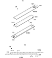
- FIG. 1 is a top view, the 1st side view, and the 2nd side view of piezoelectric actuator 10 used for tactile sense presentation device 9 concerning a 1st embodiment of the present invention. It is the top view which expanded the piezoelectric actuator 10 used for the tactile sense presentation apparatus 9 which concerns on the 1st Embodiment of this invention partially.
- (A) is an exploded perspective view showing an electrode pattern for applying a driving voltage to the piezoelectric actuator 10 used in the tactile sense presentation device 9 according to the first embodiment of the present invention, and FIG. It is sectional drawing in the line shown by).
- FIG. 1 is an external perspective view for explaining the behavior of the piezoelectric actuator 10
- (B) is a partially enlarged plan view of a connection portion between the first flat plate portion 101 and the second flat plate portion 102. It is a disassembled perspective view for demonstrating the structure of the tactile sense presentation apparatus 9 which concerns on the 1st Embodiment of this invention.
- 3 is a partially enlarged exploded perspective view for explaining the installation structure of the piezoelectric actuator 10.
- FIG. It is a top view which shows the example of a behavior of the touch panel 97 with respect to the housing
- piezoelectric actuator 10C used for the tactile sense presentation apparatus 9A which concerns on the 2nd Embodiment of this invention, and the 1st, 2nd, 3rd, 4th side view. It is the top view which expanded partially the piezoelectric actuator 10C used for the tactile sense presentation apparatus 9A which concerns on the 2nd Embodiment of this invention. It is a disassembled perspective view for demonstrating the structure of 9 A of tactile sense presentation apparatuses which concern on the 2nd Embodiment of this invention. It is a top view which shows the example of a behavior of the touch panel 97 with respect to the housing
- FIG. 15A is an external perspective view showing a configuration of a piezoelectric actuator 10J using the piezoelectric element 200J
- FIG. 15B is an exploded perspective view thereof.
- (A) is an exploded perspective view showing a configuration of a piezoelectric actuator 10K using two flat elastic bodies and one piezoelectric element
- FIG. 16 (B) is a sectional view taken along the line shown in FIG. 16 (A). It is. It is a figure which shows the other structure of the piezoelectric actuator with which the elongate direction of a 1st flat plate part and a 2nd flat plate part orthogonally crosses.
- FIG. 1 is a plan view, a first side view, and a second side view of a piezoelectric actuator 10 used in the tactile presentation device 9 according to the present embodiment.
- FIG. 2 is a partially enlarged plan view of the piezoelectric actuator 10.
- the piezoelectric actuator 10 corresponds to the “vibration means” of the present invention, and includes a long and flat elastic body 100.
- the elastic body 100 is made of an insulating material.
- the length (length in the longitudinal direction) is 24 mm
- the width (length in the direction perpendicular to the longitudinal direction of the flat plate surface) is 3 mm
- the thickness is 0.2 mm. It is said.
- the dimensions of the elastic body 100 are not limited to this, and may be set as appropriate according to the desired vibration characteristics, the maximum outer shape, and the like.
- the elastic body 100 may be made of a conductive material, and may be made of a metal material such as stainless steel or copper.
- the elastic body 100 includes a first flat plate portion 101 and a second flat plate portion 102.
- the first flat plate portion 101 and the second flat plate portion 102 are connected to each other in the longitudinal direction opposite to each other by the first narrow width portion 104.
- the first narrow width portion 104 is formed to be narrower than the first flat plate portion 101 and the second flat plate portion 102.
- the first narrow width portion 104 is formed to have a width of about 1/5 with respect to the width of the first flat plate portion 101 and the second flat plate portion 102.
- a third flat plate portion 103 is formed near the end of the first flat plate portion 101 on the second flat plate portion 102 side.
- the third flat plate portion 103 has a substantially circular shape in plan view and is separated from the first flat plate portion 101.
- the third flat plate portion 103 is connected to the second flat plate portion 102 by the second narrow width portion 105.
- the second narrow width portion 105 is also formed with a narrow width with respect to the first flat plate portion 101 and the second flat plate portion 102 and further with respect to the third flat plate portion 103.
- the second narrow portion 105 is formed to have a width comparable to that of the first narrow portion 104.
- each through-hole 121, 122, 123 may be set as appropriate.
- the through-hole 123 functions as a fulcrum described later, the fixed third flat plate portion 103 moves even when an external force is applied. It is better if the shape is difficult.
- the through-hole 123 is preferably a rectangular opening.
- a long piezoelectric element 200 is disposed on each main surface (both flat plate surfaces) of the first flat plate portion 101.
- the longitudinal direction of the piezoelectric element 200 and the length direction of the first flat plate portion 101 coincide with each other, and the side surfaces at both ends in the width direction coincide with the first flat plate portion 101 in plan view.
- the first flat plate portion 101 is disposed.
- the piezoelectric element 200 has a length (length in the longitudinal direction) of 16 mm and a width (a direction orthogonal to the longitudinal direction of the flat plate surface). Is 3 mm and the thickness is 0.2 mm.
- the piezoelectric element 200 is disposed on the first flat plate portion 101 so as not to block the through-hole 121 in plan view.
- the piezoelectric element 200 corresponds to the “drive element” of the present invention.
- the piezoelectric elements 200 disposed on both main surfaces of the first flat plate portion 101 are arranged so as to coincide with each other when viewed from a direction perpendicular to the flat surface that is the main surface of the piezoelectric element 200 and the first flat plate portion 101.
- One flat plate portion 101 is disposed.
- the piezoelectric element 200 includes a long piezoelectric body portion made of piezoelectric ceramic, and electrodes for applying a driving voltage formed on both ends of the piezoelectric body portion in the thickness direction, that is, on opposing flat plate surfaces. It is driven in d31 mode by applying a driving voltage. At this time, when the same drive voltage is applied to each piezoelectric element 200, the piezoelectric element 200 is configured to expand and contract with the same displacement amount in the same longitudinal direction, and an electrode corresponding to such drive. A pattern is formed on each piezoelectric element 200.
- FIG. 3A is an exploded perspective view showing an electrode pattern for applying a driving voltage to the piezoelectric actuator 10 of this embodiment
- FIG. 3B is a cross-sectional view taken along the line shown in FIG.
- a first counter electrode 211 is formed on the surface opposite to the first flat plate portion 101.
- the first counter electrode 211 is formed on the entire upper surface side of the piezoelectric element 200.
- a second counter electrode 212 is formed on the surface on the first flat plate portion 101 side.
- the second counter electrode 212 is formed over the entire width of the piezoelectric element 200, but in the longitudinal direction, a predetermined region becomes a non-forming region from the end portion on the through hole 121 side of the first flat plate portion 101. Is formed. In this non-formation region, a first connection electrode 211A connected to the first counter electrode 211 via a side electrode is formed.
- an upper surface side wiring electrode 111 connected to the second counter electrode 212 is formed, and an upper surface side wiring electrode 113 connected to the first connection electrode 211A is formed.
- the upper surface side wiring electrodes 111 and 113 have one end reaching the end portion on the through hole 121 side of the first flat plate portion 101 and the other end overlapping the second counter electrode 212 and the first connection electrode 211A in plan view, respectively. It is formed to extend to a position.
- the other end of the upper surface side wiring electrode 113 is formed to extend to the vicinity of the end portion on the through hole 121 side of the piezoelectric element 200, and the other end of the upper surface side wiring electrode 111 is the second flat plate portion 102 side of the piezoelectric element 200. It is formed in the shape extended to the edge part vicinity.
- lower surface side wiring electrodes 112 and 114 are formed symmetrically with respect to the upper surface side wiring electrodes 111 and 113 with respect to the first flat plate portion 101. ing.
- the upper surface side wiring electrode 111 and the lower surface side wiring electrode 112 are connected by a conductive through hole 115A.
- the upper surface side wiring electrode 113 and the lower surface side wiring electrode 114 are connected by a conductive through hole 115B.
- These conductive through holes 115 ⁇ / b> A and 115 ⁇ / b> B are formed near the end portion of the first flat plate portion 101 on the through hole 121 side.
- a third counter electrode 213 is formed on the surface opposite to the first flat plate portion 101.
- the third counter electrode 213 is formed on the entire lower surface of the piezoelectric element 200.
- a fourth counter electrode 214 is formed on the surface on the first flat plate portion 101 side. The fourth counter electrode 214 is formed over the entire width of the piezoelectric element 200, but in the longitudinal direction, a predetermined region becomes a non-forming region from the end portion on the through hole 121 side of the first flat plate portion 101. Is formed.
- a third connection electrode 213A connected to the third counter electrode 213 via a side electrode is formed. That is, the first counter electrode 211, the second counter electrode 212, and the first connection electrode 211A formed on the piezoelectric element 200 disposed on the upper surface side of the first flat plate portion 101 of the elastic body 100 are first.
- a third counter electrode 213, a fourth counter electrode 214, and a third connection electrode 213A are formed symmetrically with respect to the flat plate portion 101.
- the set of the upper surface side wiring electrode 111 and the lower surface side wiring electrode 112 is set to the first potential, and the set of the upper surface side wiring electrode 113 and the lower surface side wiring electrode 114 is reversed from the first potential.
- the piezoelectric elements 200 disposed on both surfaces of the first flat plate portion 101 expand and contract in the longitudinal direction.
- the stress due to the expansion / contraction motion of the piezoelectric element 200 is transmitted to the first flat plate portion 101, and the first flat plate portion 101 vibrates.
- This vibration acts on the second flat plate portion 102 via the first narrow portion 104.
- the 2nd flat plate part 102 vibrates.
- the piezoelectric actuator 10 functions as a bimorph type piezoelectric actuator.
- the piezoelectric element 200 is formed of a material having a smaller linear expansion coefficient than the elastic body 100.
- stress in the compression direction is applied to the piezoelectric element 200 due to the difference in the linear expansion coefficient between the piezoelectric element 200 and the elastic body 100, so that the mechanical strength is improved. Can do.
- the strength against external force applied to the piezoelectric element 200 can be improved.
- the piezoelectric actuator 10 having such a configuration exhibits the following behavior.
- 4A is an external perspective view for explaining the behavior of the piezoelectric actuator 10
- FIG. 4B is a plan view in which a connection portion between the first flat plate portion 101 and the second flat plate portion 102 is partially enlarged. .
- the piezoelectric actuator 10 is fixed to a housing (not shown) by screws or the like for inserting the through holes 121 and 123. Therefore, the end portion of the first flat plate portion 101 on the through hole 121 side, in other words, the end portion of the first flat plate portion 101 opposite to the second flat plate portion 102, and the third flat plate portion 103 are fixed to the housing. It does not move.
- the first flat plate portion 101 is elongated in the longitudinal direction due to the stress along the longitudinal direction applied from the piezoelectric element 200 and the elasticity of the elastic body 100. Vibrates along.
- the third flat plate portion 103 is fixed, and the second flat plate portion 102 is connected to the third flat plate portion 103 via the second narrow width portion 105, whereby the second flat plate portion 102.
- connection end of the first narrow portion 104 of the first flat plate portion 101 is used as a power point
- connection end of the second narrow portion 105 of the third flat plate portion 103 is used as a fulcrum.
- the lever principle the second flat plate portion 102 vibrates in an arc shape. Then, using such a lever principle, if the end of the second flat plate portion 102 opposite to the first flat plate portion 101 is used as an action point, the point between the force point and the fulcrum (the first narrow width portion 104 and the second narrow width portion 104).
- the distance between the fulcrum and the action point is significantly longer than the distance of the width portion 105), so that an arc-shaped vibration having a vibration amount larger than the vibration amount of the first flat plate portion 101 is exerted.
- a vibration transmission means for example, a touch panel described later
- the expansion and contraction movement of the relatively small piezoelectric element 200 A vibration having a larger amplitude can be given to the vibration transmitting means.
- the width of the first narrow portion 104 is W4
- the width of the second narrow portion 105 is W5
- W6> W6 and W5> W6 are preferable when the width of the opening 106 between is W6.
- the width W4 of the first narrow portion 104 and the width W5 of the second narrow portion 105 are appropriately set in consideration of the mechanical strength in the width direction and the resistance to arc-shaped vibration due to the width. do it. For example, it may be about 1/5 of the width of the first flat plate portion 101 and the second flat plate portion 102.
- FIG. 5 is an exploded perspective view for explaining the structure of the tactile presentation device 9 of the present embodiment.
- FIG. 6 is a partially enlarged exploded perspective view for explaining the installation structure of the piezoelectric actuator 10.
- the tactile sense presentation device 9 includes piezoelectric actuators 10A and 10B corresponding to the piezoelectric actuator 10 described above, a housing 90, and a front member 91 to which a touch panel 97 serving as the vibration transmission means is fixed.
- the housing 90 has a predetermined thickness, a rectangular shape in plan view, and has a flat first main surface.
- the housing 90 is formed with taps (screw holes) 93A, 93B, 94A, 94B for installing the piezoelectric actuators 10A, 10B at a pair of diagonal positions.
- through grooves 95A and 95B are formed at the diagonal positions, respectively.
- the through grooves 95 ⁇ / b> A and 95 ⁇ / b> B are formed in such a shape that screws 85 ⁇ / b> A and 85 ⁇ / b> B, which will be described later, do not contact the housing 90 due to vibrations of the piezoelectric actuator 10 ⁇ / b> A described later.
- the taps 93 ⁇ / b> A and 94 ⁇ / b> A and the through-groove 95 ⁇ / b> A are formed along the longitudinal direction in the vicinity of one end of the casing 90 in the short direction.
- the taps 93 ⁇ / b> B and 94 ⁇ / b> B and the through groove 95 ⁇ / b> B are formed along the longitudinal direction in the vicinity of the other end of the housing 90 in the short direction.
- the taps 94A and 94B are provided with side walls having an outer shape (square in a plan view) corresponding to the opening shapes of the through holes 123A and 123B of the piezoelectric actuators 10A and 10B.
- the portions of the third flat plate portions 103A and 103B located around the through holes 123A and 123B are fixed, and the force by the piezoelectric actuators 10A and 10B described above is applied to the third flat plate portions 103A and 103B. Even if it adds, it can prevent that 3rd flat plate part 103A, 103B slips and rotates. Thereby, 3rd flat plate part 103A, 103B can be fixed to the housing
- the front member 91 is a cover member, and a touch panel 97 is fixed to the housing 90 side.
- the front member 91 has a substantially identical outer shape in plan view to that of the housing 90 and includes an opening region 92 in the center.
- the area of the opening area 92 is set according to the display area of the touch panel 97 to be fixed.
- the front member 91 has taps 96A (not shown) and 96B for connecting to the piezoelectric actuators 10A and 10B, respectively, at a pair of diagonal positions.
- the piezoelectric actuators 10A and 10B are installed on the surface of the housing 90 opposite to the front member 91.
- the piezoelectric actuators 10 ⁇ / b> A and 10 ⁇ / b> B are arranged so that the longitudinal direction is along the longitudinal direction of the housing 90.
- a screw 83A is inserted into the through hole 121A of the piezoelectric actuator 10A, and the screw 83A is screwed into the tap 93A of the housing 90.
- a screw 84A is inserted into the through hole 123A of the piezoelectric actuator 10A, and the screw 84A is screwed into the tap 94A of the housing 90. Accordingly, the end portion of the piezoelectric actuator 10A on the first flat plate portion 101A side and the third flat plate portion 103A are fixed to the housing 90.
- a screw 85A is inserted into the through hole 122A of the piezoelectric actuator 10A, and the screw 85A is inserted into the through groove 95A of the housing 90 and screwed into the tap 96A of the front member 91.
- the end of the piezoelectric actuator 10A on the second flat plate portion 102A side is fixed to the front member 91.
- a screw 83B is inserted into the through hole 121B of the piezoelectric actuator 10B, and the screw 83B is screwed into the tap 93B of the housing 90.
- a screw 84B is inserted into the through hole 123B of the piezoelectric actuator 10B, and the screw 84B is screwed into the tap 94B of the housing 90. Thereby, the end on the first flat plate portion 101B side of the piezoelectric actuator 10B and the third flat plate portion 103B are fixed to the housing 90.
- a screw 85B is inserted into the through hole 122B of the piezoelectric actuator 10B, and the screw 85B is inserted into the through groove 95B of the housing 90 and screwed into the tap 96B of the front member 91. Accordingly, the end portion of the piezoelectric actuator 10B on the second flat plate portion 102B side is fixed to the front member 91.
- FIG. 7 is a plan view illustrating a behavior example of the touch panel 97 with respect to the housing 90 in the tactile sense presentation device 9 according to the present embodiment.
- the expansion and contraction motion of the piezoelectric elements 200 of the piezoelectric actuators 10A and 10B (vibration motion along the longitudinal direction of the housing 90 (thick arrows 901A and 901B))
- the touch panel 97 front member 91
- vibrates (thin arrows 911A and 911B) substantially along the short direction of the housing 90 (direction orthogonal to the longitudinal direction in the flat plate surface).
- the front member 91 with the touch panel 97 which is a vibration transmission means will be obtained by the piezoelectric actuators 10A and 10B having the flat surface parallel to the flat surface of the housing 90 and the front member 91. It can be vibrated in the plane of the flat plate.
- the piezoelectric actuators 10A and 10B have only to be arranged so as to overlap with the housing 90 and the front member 91 in a plan view as described above, in-plane vibration is applied to the front member 91 as shown in the prior art. Even in the case of generating the outer shape, the outer shape of the front member 91 may not be larger than the outer shape of the housing 90 in plan view. Thereby, a smaller tactile sense presentation device can be realized with the same vibration specification.
- the front member 91 can be vibrated greatly even with a relatively small vibration of the piezoelectric element 200 by the lever principle. Can realize a tactile sense presentation device.
- the piezoelectric actuators 10A and 10B can be formed with a thickness of about 1 mm or less, a thin tactile sense presentation device can be realized. Further, in order to improve the vibration characteristics, the width of the piezoelectric actuators 10A and 10B may be increased. However, in the configuration of the present embodiment, the thickness of the tactile presentation device does not change even when the width is increased. A thin tactile presentation device can be easily realized.
- the piezoelectric actuators 10A and 10B since the vibration of the front member 91 and the touch panel 97 is parallel to the flat plate surface, noise due to vibration perpendicular to the flat plate surface does not occur, and the noise can be reduced. Furthermore, as described above, when the piezoelectric actuators 10A and 10B vibrate in the plane, the piezoelectric actuators 10A and 10B do not generate noise whose vibration direction is the direction perpendicular to the flat surface, and can reduce noise. .
- the piezoelectric actuators 10A and 10B are spaced apart so that the second flat plate portions 102A and 102B are on the outer side of the housing 90. That is, it arrange
- the piezoelectric actuators 10A and 10B are arranged one by one at the diagonal positions of the housing 90.
- at least one piezoelectric actuator 10 may be disposed in the housing 90.
- the number of piezoelectric actuators 10 arranged in the housing 90 may be three or more. For example, when four piezoelectric actuators 10 are arranged, they may be arranged at the four corners of the housing 90, respectively.
- the levels and phases of driving voltages applied to the piezoelectric actuators 10 may be the same even if they are the same. It may be allowed.
- a predetermined diameter as indicated by a thin arrow 912 is obtained.
- An arc-shaped vibration can be generated.
- the diameter of the arc-shaped vibration can be changed by adjusting the voltage level difference. Thereby, more complicated vibration can be generated and the tactile sensation can be given to the operator.
- the position of the center of rotation of the arc-shaped vibration can be moved by adjusting the amplitude and phase of the piezoelectric actuators 10A and 10B.
- the operator can be given the same tactile sensation and different tactile sensations at different positions on the touch panel 97.
- the tactile sensation of the form can be presented to the operator.
- FIG. 8 is a plan view and first, second, third, and fourth side views of the piezoelectric actuator 10C used in the tactile sense presentation device 9A according to the present embodiment.
- FIG. 9 is a partially enlarged plan view of the piezoelectric actuator 10C used in the haptic presentation device 9A according to the present embodiment.
- the piezoelectric actuator 10C of the present embodiment is formed such that the second flat plate portion 102C is orthogonal to the first flat plate portion 101C, and the other configuration is the same as the piezoelectric actuator 10 shown in the first embodiment. The same. Therefore, the description of the same portions as the piezoelectric actuator 10 shown in the first embodiment is omitted.
- the long direction of the second flat plate portion 102C and the long direction of the first flat plate portion 101C are orthogonal to each other. At this time, the first flat plate portion 101C and the second flat plate portion 102C are formed so that the flat plate surface of the first flat plate portion 101C and the flat plate surface of the second flat plate portion 102C are in the same plane.
- the second flat plate portion 102C is formed to extend to the side opposite to the formation side of the third flat plate portion 103C in the width direction of the first flat plate portion 101C.
- the action point of the piezoelectric actuator 10C vibrates along a direction substantially parallel to the expansion / contraction direction of the piezoelectric element 200.
- FIG. 10 is an exploded perspective view for explaining the structure of the tactile sense presentation device 9A of the present embodiment.
- the tactile presentation device 9A of the present embodiment is different from the tactile presentation device 9 shown in the first embodiment in the installation structure of the piezoelectric actuators 10C and 10D, and the basic configuration of the other components is the same. Therefore, the description of the same part is omitted.
- the piezoelectric actuator 10C and the piezoelectric actuator 10D have the same basic structure, and the installation surface with respect to the housing 90A is reversed.
- the housing 90A is provided with taps 93C and 94C and a through groove 95C in the vicinity of one end in the short direction and at one end in the longitudinal direction.
- the tap 94C is formed at a position close to the corner of the housing 90A
- the tap 93C is formed at a predetermined distance from the tap 94C in the short direction of the housing 90A.
- a through groove 95C is formed at a predetermined distance from the tap 94C in the longitudinal direction of the housing 90A.
- the through groove 95C is formed in such a shape that the screw 85C does not contact the housing 90A due to vibration of the piezoelectric actuator 10C described later.
- the housing 90A has taps 93D and 94D and a through groove 95D formed in the vicinity of one end in the short direction and at the other end in the longitudinal direction.
- the tap 94D is formed at a position close to the corner of the housing 90A, and the tap 93D is formed at a predetermined distance from the tap 94D in the short direction of the housing 90A.
- a through groove 95D is formed at a predetermined distance from the tap 94D in the longitudinal direction of the housing 90A.
- the through groove 95D is formed in such a shape that the screw 85D does not contact the housing 90A due to vibration of the piezoelectric actuator 10D described later.
- the front member 91A includes a touch panel 97 (not shown), and taps 96C (not shown) and 96D are formed near one end in the short direction.
- a screw 83C is inserted into the through hole 121C of the piezoelectric actuator 10C, and the screw 83C is screwed into the tap 93C of the housing 90A.
- a screw 84C is inserted into the through hole 123C of the piezoelectric actuator 10C, and the screw 84C is screwed into the tap 94C of the housing 90A. Thereby, the end on the first flat plate portion 101C side of the piezoelectric actuator 10C and the third flat plate portion 103C are fixed to the housing 90A.
- a screw 85C is inserted into the through hole 122C of the piezoelectric actuator 10C, and the screw 85C is inserted into the through groove 95C of the housing 90A and screwed into a tap 96C (not shown) of the front member 91A. .
- the end of the piezoelectric actuator 10C on the second flat plate portion 102C side is fixed to the front member 91A.
- a screw 83D is inserted into the through hole 121D of the piezoelectric actuator 10D, and the screw 83D is screwed into the tap 93D of the housing 90A.
- a screw 84D is inserted into the through hole 123D of the piezoelectric actuator 10D, and the screw 84D is screwed into the tap 94D of the housing 90A. Thereby, the end on the first flat plate portion 101D side of the piezoelectric actuator 10D and the third flat plate portion 103D are fixed to the housing 90A.
- a screw 85D is inserted into the through hole 122D of the piezoelectric actuator 10D, and the screw 85D is inserted into the through groove 95D of the housing 90A and screwed into the tap 96D of the front member 91A.
- the end of the piezoelectric actuator 10D on the second flat plate portion 102D side is fixed to the front member 91A.
- FIG. 11 is a plan view illustrating a behavior example of the touch panel 97 with respect to the housing 90A in the tactile presentation device 9A according to the present embodiment.
- the piezoelectric element 200 of the piezoelectric actuators 10C and 10D expands and contracts (vibrating motion along the short direction of the housing 90A (thick arrows 901C and 901D)).
- the touch panel 97 front member 91A
- has a vibration motion tilts 911C and 911D substantially parallel to the touch panel 97.
- the vibration transmitting means is provided by the piezoelectric actuators 10C and 10D having the flat surfaces parallel to the flat surfaces of the housing 90A and the front member 91A, as in the first embodiment.
- a front member 91A with a certain touch panel 97 can be vibrated in a flat plate surface.
- the example in which the first flat plate portion of the piezoelectric actuator is formed of an elastic body having a uniform thickness as a whole is shown.
- the following configuration may be used.
- 12 and 13 are diagrams showing another configuration example of the piezoelectric actuator.
- an opening 130 penetrating in the thickness direction is formed in the first flat plate portion 101.
- the opening 130 has a rectangular shape in plan view, and is formed in a shape smaller than the area of the installation area of the piezoelectric element 200.
- a plurality of through holes 140 penetrating in the thickness direction are formed in the first flat plate portion 101.
- the through holes 140 are respectively formed in the installation area of the piezoelectric element 200.
- the shape of the through hole 140 is circular in plan view in FIG. 12B, but is not limited thereto, and may be other shapes such as a polygon. Further, the opening diameter and the opening area are not necessarily one kind.
- the first flat plate portion 101 is separated into a connection portion 1011 and a fixing portion 1012 in the installation area of the piezoelectric element 200.
- the connection portion 1011 is connected to the second flat plate portion 102 via the first narrow width portion 104.
- a through hole 121 is formed in the fixed portion 1012.
- the opening 150 that separates the connection portion 1011 and the fixing portion 1012 is configured by a plurality of shape-shaped opening grooves that extend in the longitudinal direction and grooves that connect these opening grooves in the width direction. Yes. That is, the fixed portion 1012 side of the connecting portion 1011 and the connecting portion 1011 side of the fixed portion 1012 are formed in a comb-like shape, and these are combined.
- FIGS. 12A, 12 ⁇ / b> B, and 13 ⁇ / b> A when a hole or opening penetrating in the thickness direction is formed in the first flat plate portion 101, the first expansion and contraction amount of the piezoelectric element 200 is adjusted.
- the magnitude of vibration of one flat plate portion 101 can be increased.
- FIG. 14 shows the relationship between the ratio (area ratio) between the opening area and the non-opening area in the piezoelectric element 200 installation region of the first flat plate portion 101 and the increasing rate of the vibration change amount of the first flat plate portion 101. It is a graph.
- the vibration change amount of the first flat plate portion 101 increases as the ratio of the opening area in the piezoelectric element 200 installation region of the first flat plate portion 101 increases. This is because the contact area of the first flat plate portion 101 with respect to the piezoelectric element 200 is reduced, and the force that restricts the expansion and contraction of the piezoelectric element 200 is alleviated. Thereby, it is possible to realize a piezoelectric actuator capable of generating a more effective vibration by increasing the opening area.
- the installation area of the piezoelectric element 200 in the first flat plate portion 101 is formed by the bellows structure 160. Specifically, the thickness of the bellows structure 160 region is reduced, and the region is formed in a shape that continuously curves in a side view. At this time, the maximum width in a side view is set to be equal to the other thicknesses of the first flat plate portion 101.
- FIG. 15A is an external perspective view showing a configuration of a piezoelectric actuator 10J using the piezoelectric element 200J
- FIG. 15B is an exploded perspective view thereof. In FIG. 15, only the portion corresponding to the first flat plate portion is shown.
- the piezoelectric actuator 10J includes a piezoelectric element 200J having a long shape and substantially the same width and thickness.
- the piezoelectric element 200J is made of piezoelectric ceramics such as lead zirconate titanate (PZT) and has a laminated structure.
- a fixed portion 121JA is fixed to one end in the longitudinal direction of the piezoelectric element 200J.
- a connecting portion 121JB is fixed to the other end in the longitudinal direction of the piezoelectric element 200J.
- the fixed portion 121JA and the connecting portion 121JB are formed of an elastic body having a predetermined thickness, and are disposed so that the flat plate surface is parallel to the longitudinal direction of the piezoelectric element 200J.
- a through hole 121 is formed in the fixing portion 121JA.
- the second flat plate portion 102 is connected to the connecting portion 121JB via the first narrow width portion 104, as in the above-described embodiment. Even with such a structure, the same effects as those described above can be obtained. Further, by using PZT, it is possible to drive with a lower driving voltage than the above-described various piezoelectric elements, and it is possible to simplify or omit a power supply circuit for driving the piezoelectric actuator. In addition, since no high voltage is used, the generation of noise due to the high voltage can be prevented.
- FIG. 16A is an exploded perspective view showing a configuration of a piezoelectric actuator 10K using two flat elastic bodies and one piezoelectric element
- FIG. 16B is a line shown in FIG. FIG.
- the piezoelectric actuator 10K includes a connection-side first flat plate portion 101KA, a fixed-side first flat plate member 101KB, and a piezoelectric element 200.
- the piezoelectric element 200 is held along the thickness direction by the connection-side first flat plate portion 101KA and the fixed-side first flat plate member 101KB.
- connection-side first flat plate portion 101KA is connected to the second flat plate portion 102 via the first narrow width portion 104, as in the above-described embodiment.
- a through-hole 121 is formed in the fixed first flat plate seat 101KB as in the above-described embodiment.
- a first counter electrode 211 is formed on the surface on the connection side first flat plate portion 101KA side.
- the first counter electrode 211 is formed on the entire surface of the piezoelectric element 200 on the connection side first flat plate portion 101KA side.
- a second counter electrode 212 is formed on the surface on the fixed-side first flat plate portion 101KB side.
- the second counter electrode 212 is formed over the entire width of the piezoelectric element 200, but in the longitudinal direction, a predetermined region becomes a non-forming region from the end portion on the through hole 121 side of the fixed first flat plate portion 101KB. So that it is formed. In this non-formation region, a first connection electrode 211A connected to the first counter electrode 211 via a side electrode is formed.
- An upper surface side wiring electrode 111 is formed on the upper surface of the fixed first flat plate portion 101KB so as to be connected to the second counter electrode 212, and an upper surface side wiring electrode 113 connected to the first connection electrode 211A is formed.
- These upper surface side wiring electrodes 111 and 113 have one end reaching the end portion on the through-hole 121 side of the fixed-side first flat plate portion 101KB, and the other end viewed in plan with the second counter electrode 212 and the first connection electrode 211A, respectively. Are formed to extend to the overlapping position.
- the piezoelectric element 200 is held between elastic bodies, so that the mechanical strength against external force can be improved.
- FIG. 17 is a diagram illustrating another structure of the piezoelectric actuator in which the longitudinal directions of the first flat plate portion and the second flat plate portion are orthogonal to each other. Note that the piezoelectric actuators 10L and 10M shown in FIGS. 17A and 17B have the same basic structure as the piezoelectric actuators 10C and 10D shown in the second embodiment, and only different parts will be described here.
- the extending direction of the second flat plate portion 102L serves as a fulcrum on the second narrow width portion 105L side of the first flat plate portion 101L, that is, inside the bending position of the piezoelectric actuator 10L.
- the third flat plate portion 103L and the second narrow width portion 105L are arranged.
- the piezoelectric actuator 10M shown in FIG. 17B has a structure in which the third flat plate portion 103M is formed in the inner region of the bent position without providing the third flat plate portion 103M in the width region of the first flat plate portion 101M.
- the 3rd flat plate part 103M is not formed in the width area
- a plurality of through holes 123M1 and 123M2 can be formed. That is, fulcrum-forming through holes can be formed at a predetermined number and predetermined positions without changing the shape of the first flat plate portion 101M. Thereby, the vibration characteristic can be changed by changing the through hole used for fixing.
Landscapes
- Engineering & Computer Science (AREA)
- General Engineering & Computer Science (AREA)
- Theoretical Computer Science (AREA)
- Human Computer Interaction (AREA)
- Physics & Mathematics (AREA)
- General Physics & Mathematics (AREA)
- User Interface Of Digital Computer (AREA)
Abstract
The present invention achieves a tactile sense presentation device that is able to be more compact and thinner, and is able to reduce the incidence of noise. The tactile sense presentation device (9) is provided with: a casing (90) having a flat-plate-shaped first primary surface; a vibration transmission means (97) that has a flat plate surface that is parallel to the first primary surface; and a vibration means (10A, 10B) that is connected to the casing (90) and the vibration transmission means (97) and that applies vibrations to the vibration transmission means (97). The vibration means (10A, 10B) is provided with: an elastic body (100) that is roughly flat plate shaped and that is connected to the casing (90) and the vibration transmission means (97); and a drive element (200) that applies vibrations that are parallel to the flat plate surface to the elastic body (100). The flat plate surface of the elastic body (100) is parallel to the flat plate surface of the vibration transmission means (97) and the first primary surface of the casing (90), and the vibration means (10A, 10B) is disposed in a manner so as to overlap the casing (90) and the vibration transmission means (97) in a plan view.
Description
本発明は、操作者に対して操作に応じた触覚を与えるための触覚提示装置に関する。
The present invention relates to a tactile sense presentation device for giving a tactile sense corresponding to an operation to an operator.
現在、タッチパネルに触れて操作指示を行う電子機器が、携帯電話やPDA等で各種実用化されている。このようなタッチパネル入力式の電子機器の中には、特許文献1、特許文献2に示すように、触覚提示装置を備えるものがある。
At present, various electronic devices that perform operation instructions by touching a touch panel have been put into practical use in mobile phones, PDAs, and the like. Among such touch-panel input-type electronic devices, as shown in Patent Literature 1 and Patent Literature 2, there are those equipped with a tactile sense presentation device.
触覚提示装置とは、操作者がタッチパネルに指を接触させて操作した際に、操作者に何らかの触覚、例えばタッチパネルを振動させることで力学的な感覚(触覚)等を提供する装置である。
A tactile sensation presentation device is a device that provides a mechanical sense (tactile sensation) or the like by vibrating the touch panel, for example, when the operator touches the touch panel with a finger.
このような触覚提示装置を実現するため、特許文献1に記載の触覚提示装置では、タッチパネルを囲む筐体の側壁に、アクチュエータが配置されている。アクチュエータは、側壁の壁面の法線方向に屈曲振動する構造からなる。アクチュエータはタッチパネルの側面に当接している。アクチュエータを駆動することにより、タッチパネルは主面に平行な方向へ振動する。
In order to realize such a tactile sensation presentation apparatus, in the haptic presentation apparatus described in Patent Document 1, an actuator is disposed on a side wall of a casing surrounding the touch panel. The actuator has a structure that bends and vibrates in the normal direction of the wall surface of the side wall. The actuator is in contact with the side surface of the touch panel. By driving the actuator, the touch panel vibrates in a direction parallel to the main surface.
特許文献2に記載の触覚提示装置では、矩形のタッチパネルの裏面にアクチュエータが配置されている。アクチュエータは、タッチパネルの主面に直交する方向に振動する構造からなる。アクチュエータを駆動することにより、タッチパネルは主面の法線方向へ振動する。
In the tactile presentation device described in Patent Document 2, an actuator is disposed on the back surface of a rectangular touch panel. The actuator has a structure that vibrates in a direction orthogonal to the main surface of the touch panel. By driving the actuator, the touch panel vibrates in the normal direction of the main surface.
しかしながら、特許文献1に記載の触覚提示装置では、タッチパネルの側面に当接するようにアクチュエータを配置するため、タッチパネルに対してアクチュエータを備える筐体の形状が必然的に大きくなる。また、アクチュエータの幅(長尺方向に直交する方向の長さ)方向が筐体の厚み方向となるので、触覚提示装置の厚みを薄くすると、アクチュエータの幅も薄くなり、十分な振動性能が得られなくなってしまうことがある。
However, in the tactile sense presentation device described in Patent Document 1, the actuator is arranged so as to abut on the side surface of the touch panel, and thus the shape of the housing including the actuator is inevitably increased with respect to the touch panel. In addition, since the direction of the actuator width (the length in the direction perpendicular to the longitudinal direction) is the thickness direction of the housing, if the thickness of the tactile presentation device is reduced, the width of the actuator is also reduced, and sufficient vibration performance is obtained. You may not be able to.
また、特許文献2に記載の触覚提示装置では、タッチパネルは主面の法線方向に振動するため、タッチパネルから雑音が発生してしまうことがある。
Further, in the tactile sense presentation device described in Patent Document 2, since the touch panel vibrates in the normal direction of the main surface, noise may be generated from the touch panel.
したがって、本発明の目的は、小型化、薄型化が可能であり、雑音の発生を低減できる触覚提示装置を実現することにある。
Therefore, an object of the present invention is to realize a tactile sensation presentation apparatus that can be reduced in size and thickness and can reduce noise generation.
この発明は、平板状の第1主面を有する筐体と、第1主面に平行な平板面を有する振動伝達手段と、筐体と振動伝達手段とに接続され、振動伝達手段へ振動を与える振動手段と、を備えた触覚提示装置に関する。
The present invention is connected to a housing having a flat plate-shaped first main surface, vibration transmitting means having a flat surface parallel to the first main surface, and the housing and the vibration transmitting means, and vibrates the vibration transmitting means. The present invention relates to a tactile sensation presentation apparatus including a vibration means for giving.
振動手段は、略平板状で筐体および振動伝達手段に接続されている弾性体と、該弾性体に対して平板面に平行な振動を与える駆動素子とを備える。弾性体の平板面が筐体の第1主面および振動伝達手段の平板面と平行で、且つ振動手段は平面視して筐体および振動伝達手段と重なり合うように配置されている。
The vibration means includes a substantially flat plate-like elastic body connected to the casing and the vibration transmission means, and a drive element that applies vibrations parallel to the flat plate surface to the elastic body. The flat surface of the elastic body is parallel to the first main surface of the housing and the flat surface of the vibration transmission means, and the vibration means is disposed so as to overlap the housing and the vibration transmission means in plan view.
この構成では、筐体と振動手段と振動伝達手段とが、互いの平板面が平行になるように配置され、且つ平面視して重なり合うように配置されているので、触覚提示装置において、平面視した外形形状を振動伝達手段の形状まで小さくでき、各平板の厚みの合計程度に薄くできる。また、振動伝達手段の振動方向が平板面に平行であるので、平板面の法線方向への振動が無く、これに伴う雑音が発生しない。
In this configuration, the housing, the vibration means, and the vibration transmission means are arranged so that their flat plate surfaces are parallel to each other, and are arranged so as to overlap in plan view. The outer shape can be reduced to the shape of the vibration transmitting means and can be reduced to the total thickness of each flat plate. Further, since the vibration direction of the vibration transmitting means is parallel to the flat plate surface, there is no vibration in the normal direction of the flat plate surface, and no noise is generated.
また、この発明の触覚提示装置では、次の構成であることが好ましい。弾性体は、駆動素子が配設された第1平板部と、駆動素子が配設されていない第2平板部と、第1平板部および第2平板部の幅よりも狭い形状からなり、第1平板部と第2平板部とを接続する第1狭幅部と、第1狭幅部に近接し、該第1狭幅部と略同じ形状からなる第2狭幅部によって第2平板部に接続されている第3平板部と、を備える。第1平板部の第2平板部と反対側の端部と第3平板部とが筐体に固定されている。第2平板部の第1平板部と反対側の端部が振動伝達手段に固定されている。
Also, the tactile sense presentation device of the present invention preferably has the following configuration. The elastic body has a shape that is narrower than the width of the first flat plate portion and the first flat plate portion where the drive element is disposed, the second flat plate portion where the drive element is not disposed, A first narrow portion connecting the first flat plate portion and the second flat plate portion; and a second flat plate portion by a second narrow portion adjacent to the first narrow portion and having substantially the same shape as the first narrow portion. A third flat plate portion connected to the first flat plate portion. An end of the first flat plate portion opposite to the second flat plate portion and the third flat plate portion are fixed to the housing. An end of the second flat plate portion opposite to the first flat plate portion is fixed to the vibration transmitting means.
この構成では、第3平板部が支点となり、第1狭幅部による第1平板部と第2平板部との接続部が力点となり、第2平板部の第1平板部と反対側の端部すなわち振動伝達手段への接続部が作用点となる。この構成により、力点と支点との距離が短く、支点と作用点と距離が長くなる。これにより、力点に加わる第1平板部の振動に対して、第2平板部の作用点での振動が大きくなり、効果的な振動伝達が可能になる。さらに、第1狭幅部の幅が狭いことにより、第2平板部の振動に対する規制力を抑制でき、より高効率な振動伝達が可能になる。
In this configuration, the third flat plate portion serves as a fulcrum, the connecting portion between the first flat plate portion and the second flat plate portion by the first narrow width portion serves as a power point, and the end portion of the second flat plate portion opposite to the first flat plate portion. That is, the connection point to the vibration transmission means becomes the action point. With this configuration, the distance between the force point and the fulcrum is short, and the distance between the fulcrum and the action point is long. Thereby, with respect to the vibration of the first flat plate portion applied to the power point, the vibration at the action point of the second flat plate portion is increased, and effective vibration transmission becomes possible. Furthermore, since the width of the first narrow portion is narrow, the regulation force for the vibration of the second flat plate portion can be suppressed, and more efficient vibration transmission becomes possible.
また、この発明の触覚提示装置では、駆動素子は圧電素子であり、当該圧電素子は、第1平板部の両主面に配設されていることが好ましい。
In the tactile sense presentation device of the present invention, it is preferable that the driving element is a piezoelectric element, and the piezoelectric element is disposed on both main surfaces of the first flat plate portion.
この構成では、第1平板部の主面である平板面に垂直な方向に対する圧電素子の振動が小さく、平板面に平行な振動が振動の主体になるので、平板面に垂直な方向の振動による雑音を小さくすることができる。
In this configuration, the vibration of the piezoelectric element with respect to the direction perpendicular to the flat plate surface, which is the main surface of the first flat plate portion, is small, and the vibration parallel to the flat plate surface is the main component of the vibration. Noise can be reduced.
また、この発明の触覚提示装置では、第1平板部の両主面に配設されたそれぞれの圧電素子は、駆動時の変形方向と変形量が互いに一致する形状で形成されていることが好ましい。
In the tactile sense presentation device of the present invention, it is preferable that the piezoelectric elements disposed on both main surfaces of the first flat plate portion are formed in a shape in which the deformation direction and the deformation amount during driving coincide with each other. .
この構成では、平板面に沿った振動による第1平板部の伸縮運動をより効果的に行え、且つ、平板面に垂直な方向の振動がより小さくなる。
In this configuration, the expansion and contraction motion of the first flat plate portion due to the vibration along the flat plate surface can be more effectively performed, and the vibration in the direction perpendicular to the flat plate surface is further reduced.
また、この発明の触覚提示装置では、駆動素子は圧電素子であり、該圧電素子は第1平板部の両主面に、第1平板部側の電位が一致するように配設されていることが好ましい。
In the tactile sense presentation device according to the present invention, the driving element is a piezoelectric element, and the piezoelectric element is disposed on both main surfaces of the first flat plate portion so that the potentials on the first flat plate portion side coincide with each other. Is preferred.
この構成では、駆動素子を圧電素子で構成し、バイモルフ構造にしている。この圧電素子をd31モードで駆動することで、圧電素子が平板面に沿って伸縮し、当該圧電素子の伸縮と弾性体の弾性によって、弾性体が平板面に沿って振動する。また、弾性体により圧電素子へ加わる外力に対する強度を補強できる。
In this configuration, the driving element is composed of a piezoelectric element and has a bimorph structure. By driving this piezoelectric element in the d31 mode, the piezoelectric element expands and contracts along the flat plate surface, and the elastic body vibrates along the flat plate surface by the expansion and contraction of the piezoelectric element and the elasticity of the elastic body. Further, the strength against external force applied to the piezoelectric element can be reinforced by the elastic body.
また、この発明の触覚提示装置では、第1平板部は平板面が平行な二枚の弾性体からなる固定部と接続部とからなり、接続部は第2平板部と接続されており、駆動素子は固定部と接続部とに当接するように固定部と接続部との間へ配設されている、ようにしてもよい。
In the tactile sense presentation device according to the present invention, the first flat plate portion includes a fixed portion and a connection portion made of two elastic bodies whose flat plate surfaces are parallel, and the connection portion is connected to the second flat plate portion, and is driven. The element may be disposed between the fixed portion and the connection portion so as to abut on the fixed portion and the connection portion.
この構成では、駆動素子を二枚の弾性体で狭持する構造を用いている。これにより、弾性体が駆動素子を保護し、駆動素子へ加わる外力に対する強度を補強できる。
In this configuration, a structure in which the driving element is sandwiched between two elastic bodies is used. Thereby, an elastic body can protect a drive element and can reinforce the intensity to external force applied to a drive element.
また、この発明の触覚提示装置では、第1平板部は、駆動素子の配設領域に、少なくとも部分的に厚みを薄くした領域もしくは開口領域を備える、ことが好ましい。
In the tactile sense presentation device according to the present invention, it is preferable that the first flat plate portion includes an area where the drive element is disposed or an area where the thickness is reduced at least partially.
この構成では、弾性体の変位量が増加し、より効率的に振動を発生できる。
This configuration increases the amount of displacement of the elastic body and can generate vibration more efficiently.
また、この発明の触覚提示装置では、第1平板部は、固定部と接続部とからなり、接続部は第2平板部と接続されており、駆動素子の長手方向の両端にそれぞれ固定部と第2平板部が対向して配設されている、構成にしてもよい。
In the tactile sense presentation device according to the present invention, the first flat plate portion includes a fixed portion and a connection portion, and the connection portion is connected to the second flat plate portion, and the fixed portion is provided at both ends in the longitudinal direction of the drive element. You may make it the structure by which the 2nd flat plate part is arrange | positioned facing.
この構成では、駆動素子の振動がほぼそのまま力点に加わる。
In this configuration, the vibration of the drive element is applied almost directly to the power point.
また、この発明の触覚提示装置では、第1平板部と第2平板部とは長手方向が一致する、構成にすることができる。
Moreover, in the tactile sense presentation device of the present invention, the first flat plate portion and the second flat plate portion can be configured such that their longitudinal directions coincide.
この構成では、第1平板部の振動方向に対して同じ平面内の直交する方向への振動を振動伝達手段へ与えることができる。
In this configuration, it is possible to give the vibration transmitting means vibration in a direction orthogonal to the vibration direction of the first flat plate portion in the same plane.
また、この発明の触覚提示装置では、第1平板部と第2平板部とは長手方向が直交する、構成にすることができる。
Moreover, in the tactile sense presentation device of the present invention, the first flat plate portion and the second flat plate portion can be configured such that their longitudinal directions are orthogonal to each other.
この構成では、第1平板部の振動方向と同じ方向の振動を振動伝達手段へ与えることができる。
In this configuration, vibration in the same direction as the vibration direction of the first flat plate portion can be applied to the vibration transmitting means.
また、この発明の触覚提示装置では、振動伝達手段はタッチパネルである、構成にすることができる。
Moreover, in the tactile sense presentation device of the present invention, the vibration transmission means may be a touch panel.
この構成では、タッチパネルを操作した操作者に対して、上記振動による触覚を与える触覚提示装置を実現できる。
In this configuration, it is possible to realize a tactile sensation presentation device that gives a tactile sensation by the vibration to an operator who operates the touch panel.
また、この発明の触覚提示装置のタッチパネルの少なくとも一部は透光性を有することが好ましい。この構成では、タッチパネルの具体的な光学特性を示している。
Moreover, it is preferable that at least a part of the touch panel of the tactile presentation device of the present invention has translucency. This configuration shows specific optical characteristics of the touch panel.
また、この発明の触覚提示装置では、タッチパネルの主面の形状は矩形平板状である。
Moreover, in the tactile sense presentation device of the present invention, the shape of the main surface of the touch panel is a rectangular flat plate.
この発明によれば、小型且つ薄型であって、雑音の発生が無い高性能な触覚提示装置を実現することができる。
According to the present invention, a high-performance tactile presentation device that is small and thin and does not generate noise can be realized.
本発明の第1の実施形態に係る触覚提示装置9について、図を参照して説明する。図1は、本実施形態に係る触覚提示装置9に用いられる圧電アクチュエータ10の平面図、第1側面図および第2側面図である。図2は、圧電アクチュエータ10を部分拡大した平面図である。
The tactile sense presentation device 9 according to the first embodiment of the present invention will be described with reference to the drawings. FIG. 1 is a plan view, a first side view, and a second side view of a piezoelectric actuator 10 used in the tactile presentation device 9 according to the present embodiment. FIG. 2 is a partially enlarged plan view of the piezoelectric actuator 10.
圧電アクチュエータ10は、本発明の「振動手段」に相当し、長尺状で平板状の弾性体100を備える。弾性体100は、絶縁性材料からなり、例えば長さ(長尺方向の長さ)を24mm、幅(平板面の長尺方向に直交する方向の長さ)を3mmとし、厚みを0.2mmとしている。なお、弾性体100の寸法は、これに限るものではなく、所望とする振動特性や外形形状の最大寸などに応じて適宜設定すればよい。また、弾性体100は、導電材料からなるものであってもよく、例えばステンレス鋼、銅などの金属材料からなるものであってもよい。
The piezoelectric actuator 10 corresponds to the “vibration means” of the present invention, and includes a long and flat elastic body 100. The elastic body 100 is made of an insulating material. For example, the length (length in the longitudinal direction) is 24 mm, the width (length in the direction perpendicular to the longitudinal direction of the flat plate surface) is 3 mm, and the thickness is 0.2 mm. It is said. The dimensions of the elastic body 100 are not limited to this, and may be set as appropriate according to the desired vibration characteristics, the maximum outer shape, and the like. The elastic body 100 may be made of a conductive material, and may be made of a metal material such as stainless steel or copper.
弾性体100は、第1平板部101と第2平板部102とを備える。第1平板部101と第2平板部102は、互いの対向する長手方向の端部同士が第1狭幅部104によって接続されている。第1狭幅部104は、第1平板部101および第2平板部102に対して、狭い幅に形成されている。例えば、第1狭幅部104は、第1平板部101および第2平板部102の幅に対して1/5程度の幅に形成されている。
The elastic body 100 includes a first flat plate portion 101 and a second flat plate portion 102. The first flat plate portion 101 and the second flat plate portion 102 are connected to each other in the longitudinal direction opposite to each other by the first narrow width portion 104. The first narrow width portion 104 is formed to be narrower than the first flat plate portion 101 and the second flat plate portion 102. For example, the first narrow width portion 104 is formed to have a width of about 1/5 with respect to the width of the first flat plate portion 101 and the second flat plate portion 102.
第1平板部101の第2平板部102側の端部付近には、第3平板部103が形成されている。第3平板部103は、平面視した形状が略円形であり、第1平板部101からは離間している。第3平板部103は、第2狭幅部105によって第2平板部102へ接続されている。第2狭幅部105も、第1狭幅部104と同様に、第1平板部101および第2平板部102に対して、さらには第3平板部103に対して狭い幅に形成されている。例えば、第2狭幅部105は、第1狭幅部104と同程度の幅に形成されている。
Near the end of the first flat plate portion 101 on the second flat plate portion 102 side, a third flat plate portion 103 is formed. The third flat plate portion 103 has a substantially circular shape in plan view and is separated from the first flat plate portion 101. The third flat plate portion 103 is connected to the second flat plate portion 102 by the second narrow width portion 105. Similarly to the first narrow width portion 104, the second narrow width portion 105 is also formed with a narrow width with respect to the first flat plate portion 101 and the second flat plate portion 102 and further with respect to the third flat plate portion 103. . For example, the second narrow portion 105 is formed to have a width comparable to that of the first narrow portion 104.
この際、第1狭幅部104と第2狭幅部105とは、近接して形成されている。具体的には、図2に示すように、第1狭幅部104の幅をW4とし、第2狭幅部105の幅をW5とし、第1狭幅部104と第2狭幅部105とを離間する開口部106の幅をW6とした場合、W4=(≒)W5>W6の関係となるようにする。
At this time, the first narrow portion 104 and the second narrow portion 105 are formed close to each other. Specifically, as shown in FIG. 2, the width of the first narrow portion 104 is W4, the width of the second narrow portion 105 is W5, and the first narrow portion 104 and the second narrow portion 105 are When the width of the opening 106 that separates is W6, W4 = (≈) W5> W6.
第1平板部101は、第2平板部102との接続端と反対側の端部に、厚み方向へ貫通した貫通孔121が形成されている。第2平板部102は、第1平板部101との接続端と反対側の端部に、厚み方向へ貫通した貫通孔122が形成されている。第3平板部103は、平面視した略中央に、厚み方向へ貫通した貫通孔123が形成されている。各貫通孔121,122,123の開口形状は適宜設定すればよいが、特に、貫通孔123は、後述する支点として機能するため、外力が加わっても固定されている第3平板部103が動きにくい形状であるとよりよい。例えば、図1、図2に示すように、貫通孔123は方形状の開口であるとよい。
In the first flat plate portion 101, a through hole 121 penetrating in the thickness direction is formed at the end opposite to the connection end with the second flat plate portion 102. In the second flat plate portion 102, a through hole 122 penetrating in the thickness direction is formed at the end opposite to the connection end with the first flat plate portion 101. The third flat plate portion 103 is formed with a through hole 123 penetrating in the thickness direction at a substantially center in a plan view. The opening shape of each through- hole 121, 122, 123 may be set as appropriate. In particular, since the through-hole 123 functions as a fulcrum described later, the fixed third flat plate portion 103 moves even when an external force is applied. It is better if the shape is difficult. For example, as shown in FIGS. 1 and 2, the through-hole 123 is preferably a rectangular opening.
第1平板部101の両主面(両平板面)には、それぞれ長尺状の圧電素子200が配設されている。この際、圧電素子200は、圧電素子200の長尺方向と第1平板部101の長さ方向とが一致し、幅方向の両端の側面が第1平板部101と平面視して一致するように、第1平板部101へ配設されている。具体的な形状としては、例えば弾性体100が上述の寸法である場合に、圧電素子200は、長さ(長尺方向の長さ)を16mm、幅(平板面の長尺方向に直交する方向の長さ)を3mmとし、厚みを0.2mmとしている。なお、この際、圧電素子200は、貫通孔121を平面視して塞がないように、第1平板部101へ配設されている。圧電素子200は、本発明の「駆動素子」に相当する。
A long piezoelectric element 200 is disposed on each main surface (both flat plate surfaces) of the first flat plate portion 101. At this time, in the piezoelectric element 200, the longitudinal direction of the piezoelectric element 200 and the length direction of the first flat plate portion 101 coincide with each other, and the side surfaces at both ends in the width direction coincide with the first flat plate portion 101 in plan view. Further, the first flat plate portion 101 is disposed. As a specific shape, for example, when the elastic body 100 has the above-described dimensions, the piezoelectric element 200 has a length (length in the longitudinal direction) of 16 mm and a width (a direction orthogonal to the longitudinal direction of the flat plate surface). Is 3 mm and the thickness is 0.2 mm. At this time, the piezoelectric element 200 is disposed on the first flat plate portion 101 so as not to block the through-hole 121 in plan view. The piezoelectric element 200 corresponds to the “drive element” of the present invention.
第1平板部101の両主面に配設される各圧電素子200は、当該圧電素子200および第1平板部101の主面である平板面に垂直な方向から見て一致するように、第1平板部101に配設されている。
The piezoelectric elements 200 disposed on both main surfaces of the first flat plate portion 101 are arranged so as to coincide with each other when viewed from a direction perpendicular to the flat surface that is the main surface of the piezoelectric element 200 and the first flat plate portion 101. One flat plate portion 101 is disposed.
圧電素子200は、圧電セラミックスからなる長尺状の圧電体部と、圧電体部の厚み方向の両端すなわち対向する平板面に形成されている駆動電圧印加用の電極とにより構成されており、当該駆動電圧の印加によりd31モードで駆動するものである。この際、各圧電素子200に同じ駆動電圧を印加した場合に、圧電素子200は長尺方向の同一方向に同一変位量で伸縮するような構造とされており、このような駆動に対応した電極パターンが各圧電素子200に形成されている。図3(A)は本実施形態の圧電アクチュエータ10に駆動電圧を印加する電極パターンを示す分解斜視図であり、図3(B)は図3(A)で示すラインでの断面図である。
The piezoelectric element 200 includes a long piezoelectric body portion made of piezoelectric ceramic, and electrodes for applying a driving voltage formed on both ends of the piezoelectric body portion in the thickness direction, that is, on opposing flat plate surfaces. It is driven in d31 mode by applying a driving voltage. At this time, when the same drive voltage is applied to each piezoelectric element 200, the piezoelectric element 200 is configured to expand and contract with the same displacement amount in the same longitudinal direction, and an electrode corresponding to such drive. A pattern is formed on each piezoelectric element 200. FIG. 3A is an exploded perspective view showing an electrode pattern for applying a driving voltage to the piezoelectric actuator 10 of this embodiment, and FIG. 3B is a cross-sectional view taken along the line shown in FIG.
弾性体100の第1平板部101の上面側に配設されている圧電素子200には、第1平板部101と反対側の面に第1対向電極211が形成されている。第1対向電極211は、圧電素子200の上面側の全面に形成されている。さらに、第1平板部101の上面側に配設されている圧電素子200には、第1平板部101側の面に第2対向電極212が形成されている。第2対向電極212は、圧電素子200の全幅に亘り形成されているが、長尺方向については、第1平板部101の貫通孔121側の端部から所定領域が非形成領域となるように、形成されている。この非形成領域には、第1対向電極211に側面電極を介して接続されている第1接続電極211Aが形成されている。
In the piezoelectric element 200 disposed on the upper surface side of the first flat plate portion 101 of the elastic body 100, a first counter electrode 211 is formed on the surface opposite to the first flat plate portion 101. The first counter electrode 211 is formed on the entire upper surface side of the piezoelectric element 200. Further, in the piezoelectric element 200 disposed on the upper surface side of the first flat plate portion 101, a second counter electrode 212 is formed on the surface on the first flat plate portion 101 side. The second counter electrode 212 is formed over the entire width of the piezoelectric element 200, but in the longitudinal direction, a predetermined region becomes a non-forming region from the end portion on the through hole 121 side of the first flat plate portion 101. Is formed. In this non-formation region, a first connection electrode 211A connected to the first counter electrode 211 via a side electrode is formed.
第1平板部101の上面には、第2対向電極212に接続される上面側配線電極111が形成されており、第1接続電極211Aに接続される上面側配線電極113が形成されている。これら上面側配線電極111,113は、一方端が第1平板部101の貫通孔121側の端部に達し、他方端がそれぞれ第2対向電極212,第1接続電極211Aと平面視して重なる位置まで延びるように形成されている。この際、上面側配線電極113の他方端が圧電素子200の貫通孔121側の端部付近まで延びる形状で形成され、上面側配線電極111の他方端が圧電素子200の第2平板部102側の端部付近まで延びる形状で形成されている。この構成により、上面側配線電極111,113が離間され、第1平板部101に駆動電圧印加用の電極パターンを引き回しても、所望の駆動電圧を、効果的に圧電素子200へ印加することができる。
On the upper surface of the first flat plate portion 101, an upper surface side wiring electrode 111 connected to the second counter electrode 212 is formed, and an upper surface side wiring electrode 113 connected to the first connection electrode 211A is formed. The upper surface side wiring electrodes 111 and 113 have one end reaching the end portion on the through hole 121 side of the first flat plate portion 101 and the other end overlapping the second counter electrode 212 and the first connection electrode 211A in plan view, respectively. It is formed to extend to a position. At this time, the other end of the upper surface side wiring electrode 113 is formed to extend to the vicinity of the end portion on the through hole 121 side of the piezoelectric element 200, and the other end of the upper surface side wiring electrode 111 is the second flat plate portion 102 side of the piezoelectric element 200. It is formed in the shape extended to the edge part vicinity. With this configuration, even if the upper surface side wiring electrodes 111 and 113 are separated from each other and a driving voltage application electrode pattern is routed around the first flat plate portion 101, a desired driving voltage can be effectively applied to the piezoelectric element 200. it can.
第1平板部101の下面(上面に対向する面)には、上面側配線電極111,113に対して、第1平板部101を基準として面対称に、下面側配線電極112,114が形成されている。上面側配線電極111と下面側配線電極112は、導電性スルーホール115Aにより、接続されている。上面側配線電極113と下面側配線電極114は、導電性スルーホール115Bにより、接続されている。これら導電性スルーホール115A,115Bは、第1平板部101の貫通孔121側の端部付近に形成されている。
On the lower surface (the surface facing the upper surface) of the first flat plate portion 101, lower surface side wiring electrodes 112 and 114 are formed symmetrically with respect to the upper surface side wiring electrodes 111 and 113 with respect to the first flat plate portion 101. ing. The upper surface side wiring electrode 111 and the lower surface side wiring electrode 112 are connected by a conductive through hole 115A. The upper surface side wiring electrode 113 and the lower surface side wiring electrode 114 are connected by a conductive through hole 115B. These conductive through holes 115 </ b> A and 115 </ b> B are formed near the end portion of the first flat plate portion 101 on the through hole 121 side.
弾性体100の第1平板部101の下面側に配設されている圧電素子200には、第1平板部101と反対側の面に第3対向電極213が形成されている。第3対向電極213は、圧電素子200の下面側の全面に形成されている。さらに、第1平板部101の下面側に配設されている圧電素子200には、第1平板部101側の面に第4対向電極214が形成されている。第4対向電極214は、圧電素子200の全幅に亘り形成されているが、長尺方向については、第1平板部101の貫通孔121側の端部から所定領域が非形成領域となるように、形成されている。この非形成領域には、第3対向電極213に側面電極を介して接続されている第3接続電極213Aが形成されている。すなわち、弾性体100の第1平板部101の上面側に配設されている圧電素子200に形成された第1対向電極211、第2対向電極212、および第1接続電極211Aに対して第1平板部101を基準として面対称に、第3対向電極213、第4対向電極214、および第3接続電極213Aが形成されている。
In the piezoelectric element 200 disposed on the lower surface side of the first flat plate portion 101 of the elastic body 100, a third counter electrode 213 is formed on the surface opposite to the first flat plate portion 101. The third counter electrode 213 is formed on the entire lower surface of the piezoelectric element 200. Further, in the piezoelectric element 200 disposed on the lower surface side of the first flat plate portion 101, a fourth counter electrode 214 is formed on the surface on the first flat plate portion 101 side. The fourth counter electrode 214 is formed over the entire width of the piezoelectric element 200, but in the longitudinal direction, a predetermined region becomes a non-forming region from the end portion on the through hole 121 side of the first flat plate portion 101. Is formed. In this non-formation region, a third connection electrode 213A connected to the third counter electrode 213 via a side electrode is formed. That is, the first counter electrode 211, the second counter electrode 212, and the first connection electrode 211A formed on the piezoelectric element 200 disposed on the upper surface side of the first flat plate portion 101 of the elastic body 100 are first. A third counter electrode 213, a fourth counter electrode 214, and a third connection electrode 213A are formed symmetrically with respect to the flat plate portion 101.
このような構成に対して、上面側配線電極111および下面側配線電極112の組を第1の電位とし、上面側配線電極113および下面側配線電極114の組を第1の電位とは正負逆符号の第2の電位とする駆動電圧を印加することで、第1平板部101の両面に配設されている圧電素子200は、長尺方向へ伸縮する。この圧電素子200の伸縮運動による応力は第1平板部101に伝わり、第1平板部101が振動する。この振動は第1狭幅部104を介して第2平板部102に作用する。これにより、第2平板部102が振動する。これにより、圧電アクチュエータ10は、バイモルフ型の圧電アクチュエータとして機能する。
For such a configuration, the set of the upper surface side wiring electrode 111 and the lower surface side wiring electrode 112 is set to the first potential, and the set of the upper surface side wiring electrode 113 and the lower surface side wiring electrode 114 is reversed from the first potential. By applying a driving voltage having the second potential, the piezoelectric elements 200 disposed on both surfaces of the first flat plate portion 101 expand and contract in the longitudinal direction. The stress due to the expansion / contraction motion of the piezoelectric element 200 is transmitted to the first flat plate portion 101, and the first flat plate portion 101 vibrates. This vibration acts on the second flat plate portion 102 via the first narrow portion 104. Thereby, the 2nd flat plate part 102 vibrates. Thereby, the piezoelectric actuator 10 functions as a bimorph type piezoelectric actuator.
そして、この構成とすることで、二枚の圧電素子200の平板面に垂直な方向の振動は殆ど生じず、平板面に沿った振動方向の最大変位量のみを大きくすることができるので、平板面に垂直な方向への雑音を発生させることなく、第1平板部101に対して、平板面に平行な方向へ大きな伸縮運動を発生させることができる。
With this configuration, vibration in the direction perpendicular to the flat plate surface of the two piezoelectric elements 200 hardly occurs, and only the maximum displacement amount in the vibration direction along the flat plate surface can be increased. A large expansion and contraction motion can be generated in the direction parallel to the flat plate surface with respect to the first flat plate portion 101 without generating noise in a direction perpendicular to the surface.
なお、圧電素子200は、弾性体100よりも線膨張係数が小さな材料により形成される。このような線膨張係数の圧電素子200を用いることで、圧電素子200と弾性体100との線膨張係数の差により、圧電素子200に圧縮方向の応力が加わるので、機械的強度を向上させることができる。
Note that the piezoelectric element 200 is formed of a material having a smaller linear expansion coefficient than the elastic body 100. By using the piezoelectric element 200 having such a linear expansion coefficient, stress in the compression direction is applied to the piezoelectric element 200 due to the difference in the linear expansion coefficient between the piezoelectric element 200 and the elastic body 100, so that the mechanical strength is improved. Can do.
また、本実施形態のように、弾性体100に圧電素子200を配設する構成とすることで、圧電素子200への外力に対する強度を向上することができる。
Further, as in this embodiment, by adopting a configuration in which the piezoelectric element 200 is disposed on the elastic body 100, the strength against external force applied to the piezoelectric element 200 can be improved.
このような構成からなる圧電アクチュエータ10は、次に示すような挙動を生じる。図4(A)は圧電アクチュエータ10の挙動を説明するための外観斜視図であり、図4(B)は第1平板部101と第2平板部102の接続部を部分拡大した平面図である。
The piezoelectric actuator 10 having such a configuration exhibits the following behavior. 4A is an external perspective view for explaining the behavior of the piezoelectric actuator 10, and FIG. 4B is a plan view in which a connection portion between the first flat plate portion 101 and the second flat plate portion 102 is partially enlarged. .
図4に示すように、圧電アクチュエータ10は、貫通孔121,123を挿嵌するネジ等により、図示しない筐体に固定されている。したがって、第1平板部101の貫通孔121側の端部、言い換えれば第1平板部101の第2平板部102と反対側の端部と、第3平板部103は、筐体に対して固定され動かない。
As shown in FIG. 4, the piezoelectric actuator 10 is fixed to a housing (not shown) by screws or the like for inserting the through holes 121 and 123. Therefore, the end portion of the first flat plate portion 101 on the through hole 121 side, in other words, the end portion of the first flat plate portion 101 opposite to the second flat plate portion 102, and the third flat plate portion 103 are fixed to the housing. It does not move.
このような固定状態において、上述のように圧電素子200に駆動電圧を印加すると、圧電素子200から加わる長尺方向に沿った応力と弾性体100の弾性により、第1平板部101は長尺方向に沿って振動する。
In such a fixed state, when the driving voltage is applied to the piezoelectric element 200 as described above, the first flat plate portion 101 is elongated in the longitudinal direction due to the stress along the longitudinal direction applied from the piezoelectric element 200 and the elasticity of the elastic body 100. Vibrates along.
この際、第1平板部101の貫通孔121側の端部が固定されていることにより、図4(B)に示すように、第1平板部101の第2平板部102側の端部と第2平板部102との距離が変化する。この第1平板部101の振動により、第2平板部102へ押す力と引く力とが交互に加わる。この力は、第1狭幅部104を介して第2平板部102へ伝達される。
At this time, since the end of the first flat plate portion 101 on the through hole 121 side is fixed, as shown in FIG. 4B, the end of the first flat plate portion 101 on the second flat plate portion 102 side and The distance with the 2nd flat plate part 102 changes. Due to the vibration of the first flat plate portion 101, a pressing force and a pulling force are alternately applied to the second flat plate portion 102. This force is transmitted to the second flat plate portion 102 via the first narrow width portion 104.
ここで、上述のように、第3平板部103が固定され、第2平板部102が第2狭幅部105を介して第3平板部103に接続されていることにより、第2平板部102は、第1平板部101から加わる力により、長尺方向に振動することはできず、第3平板部103の第3狭幅部105の接続端を基準として平板面に平行な円弧状に振動する。
Here, as described above, the third flat plate portion 103 is fixed, and the second flat plate portion 102 is connected to the third flat plate portion 103 via the second narrow width portion 105, whereby the second flat plate portion 102. Cannot vibrate in the longitudinal direction due to the force applied from the first flat plate portion 101, and vibrates in an arc shape parallel to the flat plate surface with the connection end of the third narrow portion 105 of the third flat plate portion 103 as a reference. To do.
すなわち、圧電素子200の伸縮する力に基づいて、第1平板部101の第1狭幅部104の接続端を力点とし、第3平板部103の第2狭幅部105の接続端を支点として、てこの原理によって、第2平板部102が円弧状に振動する。そして、このようなてこの原理を用い、第2平板部102の第1平板部101と反対側の端部を作用点とすれば、力点・支点間(第1狭幅部104と第2狭幅部105との間隔に略相当)の距離よりも、支点・作用点間の距離が大幅に長くなることで、第1平板部101の振動量よりも大きな振動量の円弧状振動を、作用点で実現することができる。したがって、当該作用点となる第2平板部102の貫通孔122を介して振動を伝達すべき振動伝達手段(例えば、後述のタッチパネル)を固定すれば、比較的小さな圧電素子200の伸縮運動によって、より大きな振幅の振動を振動伝達手段に与えることができる。
That is, based on the expansion and contraction force of the piezoelectric element 200, the connection end of the first narrow portion 104 of the first flat plate portion 101 is used as a power point, and the connection end of the second narrow portion 105 of the third flat plate portion 103 is used as a fulcrum. By the lever principle, the second flat plate portion 102 vibrates in an arc shape. Then, using such a lever principle, if the end of the second flat plate portion 102 opposite to the first flat plate portion 101 is used as an action point, the point between the force point and the fulcrum (the first narrow width portion 104 and the second narrow width portion 104). The distance between the fulcrum and the action point is significantly longer than the distance of the width portion 105), so that an arc-shaped vibration having a vibration amount larger than the vibration amount of the first flat plate portion 101 is exerted. Can be realized in terms. Therefore, if a vibration transmission means (for example, a touch panel described later) that should transmit vibration is fixed through the through hole 122 of the second flat plate portion 102 serving as the action point, the expansion and contraction movement of the relatively small piezoelectric element 200 A vibration having a larger amplitude can be given to the vibration transmitting means.
なお、第1狭幅部104と第2狭幅部105との間隔、すなわち力点・支点間の間隔は特に具体例を示していないが、できる限り近接させることが望ましい。具体的には、図2に示すように、第1狭幅部104の幅をW4とし、第2狭幅部105の幅をW5とし、これら第1狭幅部104と第2狭幅部105との間の開口部106の幅をW6とした場合、W4>W6、且つW5>W6であるとよい。
In addition, although the specific example is not shown about the space | interval of the 1st narrow part 104 and the 2nd narrow part 105, ie, the space | interval between a power point and a fulcrum, it is desirable to make it close as much as possible. Specifically, as shown in FIG. 2, the width of the first narrow portion 104 is W4, the width of the second narrow portion 105 is W5, and the first narrow portion 104 and the second narrow portion 105. W6> W6 and W5> W6 are preferable when the width of the opening 106 between is W6.
また、第1狭幅部104の幅W4と第2狭幅部105の幅W5は、当該幅方向への機械的強度と、当該幅による円弧状振動への抵抗力とを、鑑みて適宜設定すればよい。例えば、第1平板部101および第2平板部102の幅の1/5程度であるとよい。
In addition, the width W4 of the first narrow portion 104 and the width W5 of the second narrow portion 105 are appropriately set in consideration of the mechanical strength in the width direction and the resistance to arc-shaped vibration due to the width. do it. For example, it may be about 1/5 of the width of the first flat plate portion 101 and the second flat plate portion 102.
このような圧電アクチュエータ10を用いることで、次に示すような触覚提示装置9を実現できる。図5は、本実施形態の触覚提示装置9の構造を説明するための分解斜視図である。図6は、圧電アクチュエータ10の設置構造を説明するための部分拡大分解斜視図である。
By using such a piezoelectric actuator 10, a tactile sense presentation device 9 as shown below can be realized. FIG. 5 is an exploded perspective view for explaining the structure of the tactile presentation device 9 of the present embodiment. FIG. 6 is a partially enlarged exploded perspective view for explaining the installation structure of the piezoelectric actuator 10.
触覚提示装置9は、上述の圧電アクチュエータ10に相当する圧電アクチュエータ10A,10Bと、筐体90と、上述の振動伝達手段となるタッチパネル97が固定された正面部材91と、を備える。
The tactile sense presentation device 9 includes piezoelectric actuators 10A and 10B corresponding to the piezoelectric actuator 10 described above, a housing 90, and a front member 91 to which a touch panel 97 serving as the vibration transmission means is fixed.
筐体90は、所定厚みで、平面視した形状が長方形の外形からなり、平板状の第1主面を有する。筐体90は、一対の対角位置に、それぞれ圧電アクチュエータ10A,10Bを設置するためのタップ(ねじ穴)93A,93B,94A,94Bが形成されている。また、当該対角位置には、それぞれ貫通溝95A,95Bが形成されている。貫通溝95A,95Bは、後述する圧電アクチュエータ10Aの振動により、後述するネジ85A,85Bが筐体90に接触しない形状で形成されている。タップ93A,94A、貫通溝95Aは、筐体90の短手方向の一方の端部付近に、長手方向に沿って形成されている。同様に、タップ93B,94B、貫通溝95Bは、筐体90の短手方向の他方の端部付近に、長手方向に沿って形成されている。
The housing 90 has a predetermined thickness, a rectangular shape in plan view, and has a flat first main surface. The housing 90 is formed with taps (screw holes) 93A, 93B, 94A, 94B for installing the piezoelectric actuators 10A, 10B at a pair of diagonal positions. In addition, through grooves 95A and 95B are formed at the diagonal positions, respectively. The through grooves 95 </ b> A and 95 </ b> B are formed in such a shape that screws 85 </ b> A and 85 </ b> B, which will be described later, do not contact the housing 90 due to vibrations of the piezoelectric actuator 10 </ b> A described later. The taps 93 </ b> A and 94 </ b> A and the through-groove 95 </ b> A are formed along the longitudinal direction in the vicinity of one end of the casing 90 in the short direction. Similarly, the taps 93 </ b> B and 94 </ b> B and the through groove 95 </ b> B are formed along the longitudinal direction in the vicinity of the other end of the housing 90 in the short direction.
なお、タップ94A,94Bには、圧電アクチュエータ10A,10Bの貫通孔123A,123Bの開口形状に応じた外形(図では平面視して正方形)を有する側壁が立設されている。このような側壁を備えることで、第3平板部103A,103Bにおける貫通孔123A,123Bの周辺に位置する部分を固定し、上述の圧電アクチュエータ10A,10Bによる力が第3平板部103A,103Bに加わっても、第3平板部103A,103Bが滑って回動することを防止できる。これにより、第3平板部103A,103Bをより確実に筐体90に固定でき、支点の移動を抑制できる。この結果、より効果的な円弧状振動を実現できる。
Note that the taps 94A and 94B are provided with side walls having an outer shape (square in a plan view) corresponding to the opening shapes of the through holes 123A and 123B of the piezoelectric actuators 10A and 10B. By providing such side walls, the portions of the third flat plate portions 103A and 103B located around the through holes 123A and 123B are fixed, and the force by the piezoelectric actuators 10A and 10B described above is applied to the third flat plate portions 103A and 103B. Even if it adds, it can prevent that 3rd flat plate part 103A, 103B slips and rotates. Thereby, 3rd flat plate part 103A, 103B can be fixed to the housing | casing 90 more reliably, and the movement of a fulcrum can be suppressed. As a result, more effective arc-shaped vibration can be realized.
正面部材91は、カバー部材であり、筐体90側にタッチパネル97が固定されている。正面部材91は、平面視した外形形状が筐体90と略同じであり、中央に開口領域92を備える。開口領域92は、固定されるタッチパネル97の表示領域に応じて面積が設定されている。
The front member 91 is a cover member, and a touch panel 97 is fixed to the housing 90 side. The front member 91 has a substantially identical outer shape in plan view to that of the housing 90 and includes an opening region 92 in the center. The area of the opening area 92 is set according to the display area of the touch panel 97 to be fixed.
正面部材91は、一対の対角位置に、それぞれ圧電アクチュエータ10A,10Bに接続するためのタップ96A(図示せず),96Bが形成されている。
The front member 91 has taps 96A (not shown) and 96B for connecting to the piezoelectric actuators 10A and 10B, respectively, at a pair of diagonal positions.
圧電アクチュエータ10A,10Bは、筐体90の正面部材91と反対側の面に設置されている。圧電アクチュエータ10A、10Bは、長尺方向が筐体90の長手方向に沿うように配置されている。
The piezoelectric actuators 10A and 10B are installed on the surface of the housing 90 opposite to the front member 91. The piezoelectric actuators 10 </ b> A and 10 </ b> B are arranged so that the longitudinal direction is along the longitudinal direction of the housing 90.
圧電アクチュエータ10Aの貫通孔121Aにはネジ83Aが挿嵌され、当該ネジ83Aは筐体90のタップ93Aに螺合している。圧電アクチュエータ10Aの貫通孔123Aにはネジ84Aが挿嵌され、当該ネジ84Aは筐体90のタップ94Aに螺合している。これにより、圧電アクチュエータ10Aの第1平板部101A側の端部および第3平板部103Aは筐体90に固定される。
A screw 83A is inserted into the through hole 121A of the piezoelectric actuator 10A, and the screw 83A is screwed into the tap 93A of the housing 90. A screw 84A is inserted into the through hole 123A of the piezoelectric actuator 10A, and the screw 84A is screwed into the tap 94A of the housing 90. Accordingly, the end portion of the piezoelectric actuator 10A on the first flat plate portion 101A side and the third flat plate portion 103A are fixed to the housing 90.
圧電アクチュエータ10Aの貫通孔122Aにはネジ85Aが挿嵌され、当該ネジ85Aは、筐体90の貫通溝95Aを挿嵌し、正面部材91のタップ96Aに螺合している。これにより、圧電アクチュエータ10Aの第2平板部102A側の端部は正面部材91に固定される。
A screw 85A is inserted into the through hole 122A of the piezoelectric actuator 10A, and the screw 85A is inserted into the through groove 95A of the housing 90 and screwed into the tap 96A of the front member 91. As a result, the end of the piezoelectric actuator 10A on the second flat plate portion 102A side is fixed to the front member 91.
圧電アクチュエータ10Bの貫通孔121Bにはネジ83Bが挿嵌され、当該ネジ83Bは筐体90のタップ93Bに螺合している。圧電アクチュエータ10Bの貫通孔123Bにはネジ84Bが挿嵌され、当該ネジ84Bは筐体90のタップ94Bに螺合している。これにより、圧電アクチュエータ10Bの第1平板部101B側の端部および第3平板部103Bは筐体90に固定される。
A screw 83B is inserted into the through hole 121B of the piezoelectric actuator 10B, and the screw 83B is screwed into the tap 93B of the housing 90. A screw 84B is inserted into the through hole 123B of the piezoelectric actuator 10B, and the screw 84B is screwed into the tap 94B of the housing 90. Thereby, the end on the first flat plate portion 101B side of the piezoelectric actuator 10B and the third flat plate portion 103B are fixed to the housing 90.
圧電アクチュエータ10Bの貫通孔122Bにはネジ85Bが挿嵌され、当該ネジ85Bは、筐体90の貫通溝95Bを挿嵌し、正面部材91のタップ96Bに螺合している。これにより、圧電アクチュエータ10Bの第2平板部102B側の端部は正面部材91に固定される。
A screw 85B is inserted into the through hole 122B of the piezoelectric actuator 10B, and the screw 85B is inserted into the through groove 95B of the housing 90 and screwed into the tap 96B of the front member 91. Accordingly, the end portion of the piezoelectric actuator 10B on the second flat plate portion 102B side is fixed to the front member 91.
このような構造において、圧電アクチュエータ10A,10Bを駆動すると、上述の振動が正面部材91に伝達し、正面部材91が筐体90に対して振動する。図7は、本実施形態に係る触覚提示装置9における筐体90に対するタッチパネル97の挙動例を示す平面図である。
In such a structure, when the piezoelectric actuators 10A and 10B are driven, the above-described vibration is transmitted to the front member 91, and the front member 91 vibrates with respect to the housing 90. FIG. 7 is a plan view illustrating a behavior example of the touch panel 97 with respect to the housing 90 in the tactile sense presentation device 9 according to the present embodiment.
図7に示すように、本実施形態の構成を用いれば、圧電アクチュエータ10A,10Bの圧電素子200の伸縮運動(筐体90の長手方向に沿った振動運動(太矢印901A,901B))によって、筐体90の短手方向(平板面内の長手方向に直交する方向)に略沿ってタッチパネル97(正面部材91)が振動運動(細矢印911A,911B)する。
As shown in FIG. 7, if the configuration of this embodiment is used, the expansion and contraction motion of the piezoelectric elements 200 of the piezoelectric actuators 10A and 10B (vibration motion along the longitudinal direction of the housing 90 ( thick arrows 901A and 901B)) The touch panel 97 (front member 91) vibrates ( thin arrows 911A and 911B) substantially along the short direction of the housing 90 (direction orthogonal to the longitudinal direction in the flat plate surface).
このように、本実施形態の構成を用いれば、筐体90および正面部材91の平板面と平行な平板面を有する圧電アクチュエータ10A,10Bにより、振動伝達手段であるタッチパネル97付きの正面部材91を、平板面内で振動させることができる。
Thus, if the structure of this embodiment is used, the front member 91 with the touch panel 97 which is a vibration transmission means will be obtained by the piezoelectric actuators 10A and 10B having the flat surface parallel to the flat surface of the housing 90 and the front member 91. It can be vibrated in the plane of the flat plate.
そして、圧電アクチュエータ10A,10Bは、上述のように、平面視して筐体90および正面部材91と重なるように配置すればよいので、従来技術に示したように、正面部材91に平面内振動を生じさせる場合でも、平面視して、正面部材91の外形形状を筐体90の外形形状よりも大きくしなくてもよい。これにより、同じ振動仕様において、より小型の触覚提示装置を実現できる。
Since the piezoelectric actuators 10A and 10B have only to be arranged so as to overlap with the housing 90 and the front member 91 in a plan view as described above, in-plane vibration is applied to the front member 91 as shown in the prior art. Even in the case of generating the outer shape, the outer shape of the front member 91 may not be larger than the outer shape of the housing 90 in plan view. Thereby, a smaller tactile sense presentation device can be realized with the same vibration specification.
特に、上述の構成の場合、てこの原理により、比較的小さな圧電素子200の振動であっても、正面部材91を大きく振動できるので、同じ大きさであれば、より振動量が大きく、効果的な触覚提示装置を実現できる。
In particular, in the case of the above-described configuration, the front member 91 can be vibrated greatly even with a relatively small vibration of the piezoelectric element 200 by the lever principle. Can realize a tactile sense presentation device.
さらに、上述のように、圧電アクチュエータ10A,10Bは約1mm以下の厚みで形成できるので、薄型の触覚提示装置を実現できる。また、振動特性を向上させる場合、圧電アクチュエータ10A,10Bの幅を広くすればよいが、本実施形態の構成では、幅を広くしても触覚提示装置の厚みは変化しないので、この点においても薄型の触覚提示装置を容易に実現できる。
Furthermore, as described above, since the piezoelectric actuators 10A and 10B can be formed with a thickness of about 1 mm or less, a thin tactile sense presentation device can be realized. Further, in order to improve the vibration characteristics, the width of the piezoelectric actuators 10A and 10B may be increased. However, in the configuration of the present embodiment, the thickness of the tactile presentation device does not change even when the width is increased. A thin tactile presentation device can be easily realized.
また、上述のように、正面部材91及びタッチパネル97の振動が平板面に平行であるので、平板面に垂直な振動による雑音が発生せず、雑音を小さくすることができる。さらにまた、上述のように、圧電アクチュエータ10A,10Bが平面内で振動することにより、圧電アクチュエータ10A,10Bから、平板面に垂直な方向を振動方向とする雑音が発生せず、雑音を小さくできる。
Further, as described above, since the vibration of the front member 91 and the touch panel 97 is parallel to the flat plate surface, noise due to vibration perpendicular to the flat plate surface does not occur, and the noise can be reduced. Furthermore, as described above, when the piezoelectric actuators 10A and 10B vibrate in the plane, the piezoelectric actuators 10A and 10B do not generate noise whose vibration direction is the direction perpendicular to the flat surface, and can reduce noise. .
また、本実施形態の構成では、各圧電アクチュエータ10A,10Bは、第2平板部102A,102Bが筐体90の外方側となるように、離間して配置されている。すなわち、各圧電アクチュエータ10A,10Bによる作用点の距離を長く取るように配置されている。これにより、筐体90の中心に作用点が近づく場合よりも、正面部材91に対してより大きな振動を与えやすい。すなわち、より効果的に振動を与えられる触覚提示装置を実現できる。
Further, in the configuration of the present embodiment, the piezoelectric actuators 10A and 10B are spaced apart so that the second flat plate portions 102A and 102B are on the outer side of the housing 90. That is, it arrange | positions so that the distance of the action point by each piezoelectric actuator 10A, 10B may be taken long. Thereby, it is easy to give a greater vibration to the front member 91 than when the action point approaches the center of the housing 90. That is, it is possible to realize a tactile presentation device that can more effectively vibrate.
なお、本実施形態では、圧電アクチュエータ10A,10Bを筐体90の対角位置にそれぞれ一個ずつ配置する例を示したが、少なくとも一個の圧電アクチュエータ10を筐体90に配置すればよい。この場合、圧電アクチュエータ10が配置される位置が筐体90の角部に近いほど、効果的な振動が得られる。また、筐体90に配置される圧電アクチュエータ10は三個以上であってもよく、例えば、四個の圧電アクチュエータ10を配置する場合であれば、筐体90の四隅にそれぞれ配置すればよい。
In the present embodiment, the piezoelectric actuators 10A and 10B are arranged one by one at the diagonal positions of the housing 90. However, at least one piezoelectric actuator 10 may be disposed in the housing 90. In this case, the closer the position where the piezoelectric actuator 10 is disposed to the corner of the housing 90, the more effective vibration is obtained. Further, the number of piezoelectric actuators 10 arranged in the housing 90 may be three or more. For example, when four piezoelectric actuators 10 are arranged, they may be arranged at the four corners of the housing 90, respectively.
また、上述の説明では、詳細に示していないが、複数の圧電アクチュエータ10が筐体90に配置される場合、各圧電アクチュエータ10に与える駆動用の電圧のレベルや位相を、同じにしても異ならせてもよい。例えば、図7に示すように、二個の圧電アクチュエータ10A,10Bを用いて、異なる電圧レベルの駆動電圧を圧電アクチュエータ10A,10Bにそれぞれ印加すれば、細矢印912に示すような所定の径からなる円弧状の振動を発生させることができる。そして、この電圧レベル差を調整することで、円弧状振動の径を変化させることもできる。これにより、より複雑な振動を発生させ、その触覚を操作者へ与えることができる。
Although not shown in detail in the above description, when a plurality of piezoelectric actuators 10 are arranged in the housing 90, the levels and phases of driving voltages applied to the piezoelectric actuators 10 may be the same even if they are the same. It may be allowed. For example, as shown in FIG. 7, if two piezoelectric actuators 10A and 10B are used and drive voltages of different voltage levels are applied to the piezoelectric actuators 10A and 10B, respectively, a predetermined diameter as indicated by a thin arrow 912 is obtained. An arc-shaped vibration can be generated. The diameter of the arc-shaped vibration can be changed by adjusting the voltage level difference. Thereby, more complicated vibration can be generated and the tactile sensation can be given to the operator.
またさらに、圧電アクチュエータ10A,10Bの振幅の強弱および位相を調整するここによって、円弧状振動の回転中心の位置を移動させることができる。これにより、円弧状振動の回転中心の位置および直動振動との切り替えが可能になり、タッチパネル97上の異なる位置で操作者に、同一の触覚および異なる触覚を与えることができるので、より多様な形態の触覚を操作者に提示することができる。
Furthermore, the position of the center of rotation of the arc-shaped vibration can be moved by adjusting the amplitude and phase of the piezoelectric actuators 10A and 10B. Thereby, it is possible to switch between the position of the center of rotation of the arc-shaped vibration and the linear motion vibration, and the operator can be given the same tactile sensation and different tactile sensations at different positions on the touch panel 97. The tactile sensation of the form can be presented to the operator.
次に、本発明の第2の実施形態に係る触覚提示装置9Aについて、図を参照して説明する。図8は、本実施形態に係る触覚提示装置9Aに用いられる圧電アクチュエータ10Cの平面図、および第1,第2,第3,第4側面図である。図9は、本実施形態に係る触覚提示装置9Aに用いられる圧電アクチュエータ10Cを部分拡大した平面図である。
Next, a tactile sense presentation device 9A according to a second embodiment of the present invention will be described with reference to the drawings. FIG. 8 is a plan view and first, second, third, and fourth side views of the piezoelectric actuator 10C used in the tactile sense presentation device 9A according to the present embodiment. FIG. 9 is a partially enlarged plan view of the piezoelectric actuator 10C used in the haptic presentation device 9A according to the present embodiment.
本実施形態の圧電アクチュエータ10Cは、第2平板部102Cが第1平板部101Cに対して直交するように形成されたものであり、他の構成は第1の実施形態に示した圧電アクチュエータ10と同じである。したがって、第1の実施形態に示した圧電アクチュエータ10と同じ箇所については、説明を省略する。
The piezoelectric actuator 10C of the present embodiment is formed such that the second flat plate portion 102C is orthogonal to the first flat plate portion 101C, and the other configuration is the same as the piezoelectric actuator 10 shown in the first embodiment. The same. Therefore, the description of the same portions as the piezoelectric actuator 10 shown in the first embodiment is omitted.
第2平板部102Cの長尺方向と第1平板部101Cの長尺方向とは、直交している。この際、第1平板部101Cの平板面と第2平板部102Cの平板面は、同じ平面内となるように、第1平板部101Cおよび第2平板部102Cが形成されている。
The long direction of the second flat plate portion 102C and the long direction of the first flat plate portion 101C are orthogonal to each other. At this time, the first flat plate portion 101C and the second flat plate portion 102C are formed so that the flat plate surface of the first flat plate portion 101C and the flat plate surface of the second flat plate portion 102C are in the same plane.
第2平板部102Cは、第1平板部101Cの幅方向における第3平板部103Cの形成側と反対側に延びるように形成されている。
The second flat plate portion 102C is formed to extend to the side opposite to the formation side of the third flat plate portion 103C in the width direction of the first flat plate portion 101C.
このような構造とすることで、圧電アクチュエータ10Cの作用点は、圧電素子200の伸縮方向に略平行な方向に沿って振動する。
With this structure, the action point of the piezoelectric actuator 10C vibrates along a direction substantially parallel to the expansion / contraction direction of the piezoelectric element 200.
このような構成の圧電アクチュエータ10Cを用いることで、次に示すような触覚提示装置9Aを実現できる。図10は、本実施形態の触覚提示装置9Aの構造を説明するための分解斜視図である。
By using the piezoelectric actuator 10C having such a configuration, a tactile sense presentation device 9A as described below can be realized. FIG. 10 is an exploded perspective view for explaining the structure of the tactile sense presentation device 9A of the present embodiment.
本実施形態の触覚提示装置9Aは、圧電アクチュエータ10C,10Dの設置構造が第1の実施形態に示した触覚提示装置9と異なるものであり、他の構成要素の基本的構成は同じである。したがって、同じ箇所については説明を省略する。
The tactile presentation device 9A of the present embodiment is different from the tactile presentation device 9 shown in the first embodiment in the installation structure of the piezoelectric actuators 10C and 10D, and the basic configuration of the other components is the same. Therefore, the description of the same part is omitted.
圧電アクチュエータ10Cと圧電アクチュエータ10Dは、基本的構造が同じものであり、筐体90Aに対する設置面が逆転したものである。
The piezoelectric actuator 10C and the piezoelectric actuator 10D have the same basic structure, and the installation surface with respect to the housing 90A is reversed.
筐体90Aは、短手方向の一方端付近であって長手方向の一方端に、タップ93C,94Cおよび貫通溝95Cが形成されている。この際、タップ94Cは筐体90Aの角部に近接した位置に形成されており、当該タップ94Cから筐体90Aの短手方向に所定距離の位置にタップ93Cが形成されている。また、タップ94Cから筐体90Aの長手方向に所定距離の位置に貫通溝95Cが形成されている。貫通溝95Cは、後述する圧電アクチュエータ10Cの振動により、ネジ85Cが筐体90Aに接触しない形状で形成されている。
The housing 90A is provided with taps 93C and 94C and a through groove 95C in the vicinity of one end in the short direction and at one end in the longitudinal direction. At this time, the tap 94C is formed at a position close to the corner of the housing 90A, and the tap 93C is formed at a predetermined distance from the tap 94C in the short direction of the housing 90A. Further, a through groove 95C is formed at a predetermined distance from the tap 94C in the longitudinal direction of the housing 90A. The through groove 95C is formed in such a shape that the screw 85C does not contact the housing 90A due to vibration of the piezoelectric actuator 10C described later.
筐体90Aは、短手方向の一方端付近であって長手方向の他方端に、タップ93D,94Dおよび貫通溝95Dが形成されている。この際、タップ94Dが筐体90Aの角部に近接した位置に形成されており、当該タップ94Dから筐体90Aの短手方向に所定距離の位置にタップ93Dが形成されている。また、タップ94Dから筐体90Aの長手方向に所定距離の位置に貫通溝95Dが形成されている。貫通溝95Dは、後述する圧電アクチュエータ10Dの振動により、ネジ85Dが筐体90Aに接触しない形状で形成されている。
The housing 90A has taps 93D and 94D and a through groove 95D formed in the vicinity of one end in the short direction and at the other end in the longitudinal direction. At this time, the tap 94D is formed at a position close to the corner of the housing 90A, and the tap 93D is formed at a predetermined distance from the tap 94D in the short direction of the housing 90A. A through groove 95D is formed at a predetermined distance from the tap 94D in the longitudinal direction of the housing 90A. The through groove 95D is formed in such a shape that the screw 85D does not contact the housing 90A due to vibration of the piezoelectric actuator 10D described later.
正面部材91Aはタッチパネル97(図示せず)を備え、短手方向の一方端付近にタップ96C(図示せず),96Dが形成されている。
The front member 91A includes a touch panel 97 (not shown), and taps 96C (not shown) and 96D are formed near one end in the short direction.
圧電アクチュエータ10Cの貫通孔121Cにはネジ83Cが挿嵌され、当該ネジ83Cは筐体90Aのタップ93Cに螺合している。圧電アクチュエータ10Cの貫通孔123Cにはネジ84Cが挿嵌され、当該ネジ84Cは筐体90Aのタップ94Cに螺合している。これにより、圧電アクチュエータ10Cの第1平板部101C側の端部および第3平板部103Cは筐体90Aに固定される。
A screw 83C is inserted into the through hole 121C of the piezoelectric actuator 10C, and the screw 83C is screwed into the tap 93C of the housing 90A. A screw 84C is inserted into the through hole 123C of the piezoelectric actuator 10C, and the screw 84C is screwed into the tap 94C of the housing 90A. Thereby, the end on the first flat plate portion 101C side of the piezoelectric actuator 10C and the third flat plate portion 103C are fixed to the housing 90A.
圧電アクチュエータ10Cの貫通孔122Cにはネジ85Cが挿嵌され、当該ネジ85Cは、筐体90Aの貫通溝95Cを挿嵌し、正面部材91Aのタップ96C(図示せず)に螺合している。これにより、圧電アクチュエータ10Cの第2平板部102C側の端部は正面部材91Aに固定される。
A screw 85C is inserted into the through hole 122C of the piezoelectric actuator 10C, and the screw 85C is inserted into the through groove 95C of the housing 90A and screwed into a tap 96C (not shown) of the front member 91A. . As a result, the end of the piezoelectric actuator 10C on the second flat plate portion 102C side is fixed to the front member 91A.
圧電アクチュエータ10Dの貫通孔121Dにはネジ83Dが挿嵌され、当該ネジ83Dは筐体90Aのタップ93Dに螺合している。圧電アクチュエータ10Dの貫通孔123Dにはネジ84Dが挿嵌され、当該ネジ84Dは筐体90Aのタップ94Dに螺合している。これにより、圧電アクチュエータ10Dの第1平板部101D側の端部および第3平板部103Dは筐体90Aに固定される。
A screw 83D is inserted into the through hole 121D of the piezoelectric actuator 10D, and the screw 83D is screwed into the tap 93D of the housing 90A. A screw 84D is inserted into the through hole 123D of the piezoelectric actuator 10D, and the screw 84D is screwed into the tap 94D of the housing 90A. Thereby, the end on the first flat plate portion 101D side of the piezoelectric actuator 10D and the third flat plate portion 103D are fixed to the housing 90A.
圧電アクチュエータ10Dの貫通孔122Dにはネジ85Dが挿嵌され、当該ネジ85Dは、筐体90Aの貫通溝95Dを挿嵌し、正面部材91Aのタップ96Dに螺合している。これにより、圧電アクチュエータ10Dの第2平板部102D側の端部は正面部材91Aに固定される。
A screw 85D is inserted into the through hole 122D of the piezoelectric actuator 10D, and the screw 85D is inserted into the through groove 95D of the housing 90A and screwed into the tap 96D of the front member 91A. As a result, the end of the piezoelectric actuator 10D on the second flat plate portion 102D side is fixed to the front member 91A.
このような構造において、圧電アクチュエータ10C,10Dを駆動すると、上述の振動が正面部材91Aに伝達し、正面部材91Aが筐体90Aに対して振動する。図11は、本実施形態に係る触覚提示装置9Aにおける筐体90Aに対するタッチパネル97の挙動例を示す平面図である。
In such a structure, when the piezoelectric actuators 10C and 10D are driven, the above-described vibration is transmitted to the front member 91A, and the front member 91A vibrates with respect to the housing 90A. FIG. 11 is a plan view illustrating a behavior example of the touch panel 97 with respect to the housing 90A in the tactile presentation device 9A according to the present embodiment.
図11に示すように、本実施形態の構成を用いれば、圧電アクチュエータ10C,10Dの圧電素子200の伸縮運動(筐体90Aの短手方向に沿った振動運動(太矢印901C,901D))によって、タッチパネル97(正面部材91A)は、これに略平行な振動運動(細矢印911C,911D)となる。
As shown in FIG. 11, if the configuration of the present embodiment is used, the piezoelectric element 200 of the piezoelectric actuators 10C and 10D expands and contracts (vibrating motion along the short direction of the housing 90A ( thick arrows 901C and 901D)). The touch panel 97 (front member 91A) has a vibration motion (thin arrows 911C and 911D) substantially parallel to the touch panel 97.
このように、本実施形態の構成を用いれば、第1の実施形態と同様に、筐体90Aおよび正面部材91Aの平板面と平行な平板面を有する圧電アクチュエータ10C,10Dにより、振動伝達手段であるタッチパネル97付きの正面部材91Aを、平板面内で振動させることができる。
As described above, if the configuration of the present embodiment is used, the vibration transmitting means is provided by the piezoelectric actuators 10C and 10D having the flat surfaces parallel to the flat surfaces of the housing 90A and the front member 91A, as in the first embodiment. A front member 91A with a certain touch panel 97 can be vibrated in a flat plate surface.
また、第1の実施形態と同様に、小型化、薄型化、雑音抑制効果を実現でき、複雑な触覚を与えることもできる。
Further, similarly to the first embodiment, it is possible to achieve a reduction in size, thickness, and noise suppression effect, and to give a complex tactile sensation.
なお、上述の各実施形態では、圧電アクチュエータの第1平板部を、全体が均一な厚みからなる弾性体で形成する例を示したが、次に示すような構成であってもよい。図12,図13は、圧電アクチュエータの他の構成例を示す図である。
In each of the above-described embodiments, the example in which the first flat plate portion of the piezoelectric actuator is formed of an elastic body having a uniform thickness as a whole is shown. However, the following configuration may be used. 12 and 13 are diagrams showing another configuration example of the piezoelectric actuator.
図12(A)に示す圧電アクチュエータ10Eでは、第1平板部101に、厚み方向に貫通する開口部130が形成されている。開口部130は、平面視して矩形状からなり、圧電素子200の設置領域の面積よりも小さい形状で形成されている。
In the piezoelectric actuator 10E shown in FIG. 12A, an opening 130 penetrating in the thickness direction is formed in the first flat plate portion 101. The opening 130 has a rectangular shape in plan view, and is formed in a shape smaller than the area of the installation area of the piezoelectric element 200.
図12(B)に示す圧電アクチュエータ10Fでは、第1平板部101に、厚み方向に貫通する複数の貫通穴140が形成されている。貫通穴140は、圧電素子200の設置領域内に、それぞれ形成されている。貫通穴140の形状は、図12(B)では、平面視して円形であるが、これに限らず多角形等、他の形状であってもよい。また、開口径、開口面積も特に一種類である必要はない。
In the piezoelectric actuator 10F shown in FIG. 12 (B), a plurality of through holes 140 penetrating in the thickness direction are formed in the first flat plate portion 101. The through holes 140 are respectively formed in the installation area of the piezoelectric element 200. The shape of the through hole 140 is circular in plan view in FIG. 12B, but is not limited thereto, and may be other shapes such as a polygon. Further, the opening diameter and the opening area are not necessarily one kind.
図13(A)に示す圧電アクチュエータ10Gでは、第1平板部101は、圧電素子200の設置領域内において、接続部1011と固定部1012とに分離されている。接続部1011は、第1狭幅部104を介して第2平板部102へ接続されている。固定部1012には、貫通孔121が形成されている。接続部1011と固定部1012とを離間する開口150は、図13(A)の例では、長尺方向に延びる形状複数の開口溝と、これら開口溝を幅方向に繋ぐ溝とによって構成されている。すなわち、接続部1011の固定部1012側、および固定部1012の接続部1011側を櫛歯状に形成し、これらを組み合わせた構造となっている。
In the piezoelectric actuator 10G shown in FIG. 13A, the first flat plate portion 101 is separated into a connection portion 1011 and a fixing portion 1012 in the installation area of the piezoelectric element 200. The connection portion 1011 is connected to the second flat plate portion 102 via the first narrow width portion 104. A through hole 121 is formed in the fixed portion 1012. In the example of FIG. 13A, the opening 150 that separates the connection portion 1011 and the fixing portion 1012 is configured by a plurality of shape-shaped opening grooves that extend in the longitudinal direction and grooves that connect these opening grooves in the width direction. Yes. That is, the fixed portion 1012 side of the connecting portion 1011 and the connecting portion 1011 side of the fixed portion 1012 are formed in a comb-like shape, and these are combined.
図12(A),(B)、図13(A)に示すように、第1平板部101に対して、厚み方向に貫通する穴、開口を形成した場合、圧電素子200の伸縮量に対する第1平板部101の振動の大きさを大きくすることができる。図14は、第1平板部101の圧電素子200設置領域での開口面積と非開口面積との比(面積比)と、第1平板部101の振動変化量の増加率との関係を示したグラフである。
As shown in FIGS. 12A, 12 </ b> B, and 13 </ b> A, when a hole or opening penetrating in the thickness direction is formed in the first flat plate portion 101, the first expansion and contraction amount of the piezoelectric element 200 is adjusted. The magnitude of vibration of one flat plate portion 101 can be increased. FIG. 14 shows the relationship between the ratio (area ratio) between the opening area and the non-opening area in the piezoelectric element 200 installation region of the first flat plate portion 101 and the increasing rate of the vibration change amount of the first flat plate portion 101. It is a graph.
図14から分かるように、第1平板部101の圧電素子200設置領域での開口面積の比率が高くなるにしたがって、第1平板部101の振動変化量が大きくなることが分かる。これは、圧電素子200に対する第1平板部101の接触面積が低下し、圧電素子200の伸縮を規制する力が緩和されるからである。これにより、開口面積を大きくして、より効果的な振動発生が可能な圧電アクチュエータを実現できる。
As can be seen from FIG. 14, it can be seen that the vibration change amount of the first flat plate portion 101 increases as the ratio of the opening area in the piezoelectric element 200 installation region of the first flat plate portion 101 increases. This is because the contact area of the first flat plate portion 101 with respect to the piezoelectric element 200 is reduced, and the force that restricts the expansion and contraction of the piezoelectric element 200 is alleviated. Thereby, it is possible to realize a piezoelectric actuator capable of generating a more effective vibration by increasing the opening area.
ただし、開口面積の比率が大きくなるほど、外力に対する機械的強度は低下してしまう。したがって、第1平板部101に形成する開口面積を適宜設定することで、所望とする振動量を得ながら必要とする機械的強度を保持した圧電アクチュエータを実現することができる。
However, as the ratio of the opening area increases, the mechanical strength against external force decreases. Therefore, by appropriately setting the opening area formed in the first flat plate portion 101, it is possible to realize a piezoelectric actuator that retains the required mechanical strength while obtaining a desired vibration amount.
なお、図12(A),(B)、図13(A)に示す変形例では第1平板部101を貫通する穴、開口を形成する例を示したが、単に厚みを薄くするだけでも、同様の効果を得ることができる。
In addition, although the example which forms the hole and opening which penetrate the 1st flat plate part 101 was shown in the modification shown in Drawing 12 (A), (B), and Drawing 13 (A), even if it only makes thickness thin, Similar effects can be obtained.
図13(B)に示す圧電アクチュエータ10Hでは、第1平板部101における圧電素子200の設置領域を、蛇腹構造160で形成している。具体的には、蛇腹構造160領域の厚みを薄くし、側面視した状態で連続して湾曲するような形状で形成する。この際、側面視した最大幅は、第1平板部101の他の厚みを同じになるようにしている。
In the piezoelectric actuator 10H shown in FIG. 13B, the installation area of the piezoelectric element 200 in the first flat plate portion 101 is formed by the bellows structure 160. Specifically, the thickness of the bellows structure 160 region is reduced, and the region is formed in a shape that continuously curves in a side view. At this time, the maximum width in a side view is set to be equal to the other thicknesses of the first flat plate portion 101.
このような構造であっても、上述の開口を形成する構造と同様に、圧電素子200の伸縮量を拡大した効果的な振動を発生することができる。
Even with such a structure, it is possible to generate an effective vibration in which the amount of expansion and contraction of the piezoelectric element 200 is increased, similarly to the structure in which the opening is formed.
また、上述の説明では、圧電素子200で、第1平板部101を部分的に狭持する構成を示したが、図15、もしくは図16に示すような構造を用いてもよい。
In the above description, the configuration in which the piezoelectric plate 200 partially holds the first flat plate portion 101 is shown. However, a structure as shown in FIG. 15 or FIG. 16 may be used.
図15(A)は圧電素子200Jを用いた圧電アクチュエータ10Jの構成を示す外観斜視図であり、図15(B)はその分解斜視図である。なお、図15では、第1平板部に相当する部分のみを記載している。
FIG. 15A is an external perspective view showing a configuration of a piezoelectric actuator 10J using the piezoelectric element 200J, and FIG. 15B is an exploded perspective view thereof. In FIG. 15, only the portion corresponding to the first flat plate portion is shown.
圧電アクチュエータ10Jは、長尺状で幅および厚みが略同じ形状からなる圧電素子200Jを備える。圧電素子200Jはチタン酸ジルコン酸鉛(PZT)などの圧電セラミックスにより形成されており、積層構造からなる。圧電素子200Jの長尺方向の一方端には固定部121JAが固着されている。圧電素子200Jの長尺方向の他方端には接続部121JBが固着されている。固定部121JAと接続部121JBとは所定厚みの弾性体で形成され、平板面が圧電素子200Jの長尺方向と平行になるように、配設されている。固定部121JAには貫通孔121が形成されている。接続部121JBには、上述の実施形態と同様に、第1狭幅部104を介して第2平板部102が接続されている。このような構造であっても、上述の説明と同様の作用効果を得ることができる。さらに、PZTを用いることで、上述の各種圧電素子よりも低い駆動電圧で駆動でき、圧電アクチュエータを駆動するための電源回路を簡略化もしくは省略することができる。また、高電圧を用いないので、当該高電圧によるノイズの発生を防止できる。
The piezoelectric actuator 10J includes a piezoelectric element 200J having a long shape and substantially the same width and thickness. The piezoelectric element 200J is made of piezoelectric ceramics such as lead zirconate titanate (PZT) and has a laminated structure. A fixed portion 121JA is fixed to one end in the longitudinal direction of the piezoelectric element 200J. A connecting portion 121JB is fixed to the other end in the longitudinal direction of the piezoelectric element 200J. The fixed portion 121JA and the connecting portion 121JB are formed of an elastic body having a predetermined thickness, and are disposed so that the flat plate surface is parallel to the longitudinal direction of the piezoelectric element 200J. A through hole 121 is formed in the fixing portion 121JA. The second flat plate portion 102 is connected to the connecting portion 121JB via the first narrow width portion 104, as in the above-described embodiment. Even with such a structure, the same effects as those described above can be obtained. Further, by using PZT, it is possible to drive with a lower driving voltage than the above-described various piezoelectric elements, and it is possible to simplify or omit a power supply circuit for driving the piezoelectric actuator. In addition, since no high voltage is used, the generation of noise due to the high voltage can be prevented.
また、図16(A)は二枚の平板弾性体と一枚の圧電素子を用いた圧電アクチュエータ10Kの構成を示す分解斜視図であり、図16(B)は図16(A)に示すラインでの断面図である。圧電アクチュエータ10Kは、接続側第1平板部101KAと、固定側第1平板部材101KBと、圧電素子200とを備える。圧電素子200は、接続側第1平板部101KAと固定側第1平板部材101KBとにより、厚み方向に沿って狭持されている。
FIG. 16A is an exploded perspective view showing a configuration of a piezoelectric actuator 10K using two flat elastic bodies and one piezoelectric element, and FIG. 16B is a line shown in FIG. FIG. The piezoelectric actuator 10K includes a connection-side first flat plate portion 101KA, a fixed-side first flat plate member 101KB, and a piezoelectric element 200. The piezoelectric element 200 is held along the thickness direction by the connection-side first flat plate portion 101KA and the fixed-side first flat plate member 101KB.
接続側第1平板部101KAは、上述の実施形態と同様に、第1狭幅部104を介して第2平板部102に接続されている。固定側第1平板部座101KBには、上述の実施形態と同様に、貫通孔121が形成されている。
The connection-side first flat plate portion 101KA is connected to the second flat plate portion 102 via the first narrow width portion 104, as in the above-described embodiment. A through-hole 121 is formed in the fixed first flat plate seat 101KB as in the above-described embodiment.
接続側第1平板部101KAと固定側第1平板部材101KBとにより狭持されている圧電素子200には、接続側第1平板部101KA側の面に第1対向電極211が形成されている。第1対向電極211は、圧電素子200の接続側第1平板部101KA側の全面に形成されている。さらに、圧電素子200には、固定側第1平板部101KB側の面に第2対向電極212が形成されている。第2対向電極212は、圧電素子200の全幅に亘り形成されているが、長尺方向については、固定側第1平板部101KBの貫通孔121側の端部から所定領域が非形成領域となるように、形成されている。この非形成領域には、第1対向電極211に側面電極を介して接続されている第1接続電極211Aが形成されている。
In the piezoelectric element 200 sandwiched between the connection side first flat plate portion 101KA and the fixed side first flat plate member 101KB, a first counter electrode 211 is formed on the surface on the connection side first flat plate portion 101KA side. The first counter electrode 211 is formed on the entire surface of the piezoelectric element 200 on the connection side first flat plate portion 101KA side. Further, in the piezoelectric element 200, a second counter electrode 212 is formed on the surface on the fixed-side first flat plate portion 101KB side. The second counter electrode 212 is formed over the entire width of the piezoelectric element 200, but in the longitudinal direction, a predetermined region becomes a non-forming region from the end portion on the through hole 121 side of the fixed first flat plate portion 101KB. So that it is formed. In this non-formation region, a first connection electrode 211A connected to the first counter electrode 211 via a side electrode is formed.
固定側第1平板部101KBの上面には、第2対向電極212に接続されるように上面側配線電極111が形成されており、第1接続電極211Aに接続される上面側配線電極113が形成されている。これら上面側配線電極111,113は、一方端が固定側第1平板部101KBの貫通孔121側の端部に達し、他方端がそれぞれ第2対向電極212、第1接続電極211Aと平面視して重なる位置まで延びるように形成されている。
An upper surface side wiring electrode 111 is formed on the upper surface of the fixed first flat plate portion 101KB so as to be connected to the second counter electrode 212, and an upper surface side wiring electrode 113 connected to the first connection electrode 211A is formed. Has been. These upper surface side wiring electrodes 111 and 113 have one end reaching the end portion on the through-hole 121 side of the fixed-side first flat plate portion 101KB, and the other end viewed in plan with the second counter electrode 212 and the first connection electrode 211A, respectively. Are formed to extend to the overlapping position.
このような構造であっても、上述の実施形態に示した作用効果を得ることができる。さらに、図16の構造を用いることで、圧電素子200が弾性体に狭持されるので、外力に対する機械的強度を向上させることができる。
Even with such a structure, the operational effects shown in the above-described embodiment can be obtained. Further, by using the structure shown in FIG. 16, the piezoelectric element 200 is held between elastic bodies, so that the mechanical strength against external force can be improved.
また、上述の第2実施形態に示した圧電アクチュエータ10C,10Dに対して、次に示すような構造であっても、同様の作用効果を得ることができる。図17は、第1平板部と第2平板部との長尺方向が直交する圧電アクチュエータの他の構造を示す図である。なお、図17(A),(B)に示す圧電アクチュエータ10L,10Mは、基本構造は第2実施形態に示した圧電アクチュエータ10C,10Dと同じであり、ここでは異なる部分のみを説明する。
Further, the same effects can be obtained even if the piezoelectric actuators 10C and 10D shown in the second embodiment are structured as follows. FIG. 17 is a diagram illustrating another structure of the piezoelectric actuator in which the longitudinal directions of the first flat plate portion and the second flat plate portion are orthogonal to each other. Note that the piezoelectric actuators 10L and 10M shown in FIGS. 17A and 17B have the same basic structure as the piezoelectric actuators 10C and 10D shown in the second embodiment, and only different parts will be described here.
図17(A)に示す圧電アクチュエータ10Lでは、第2平板部102Lの延びる方向が、第1平板部101Lの第2狭幅部105L側、すなわち圧電アクチュエータ10Lの屈曲位置の内側に、支点となる第3平板部103Lおよび第2狭幅部105Lが配置される構造からなる。
In the piezoelectric actuator 10L shown in FIG. 17A, the extending direction of the second flat plate portion 102L serves as a fulcrum on the second narrow width portion 105L side of the first flat plate portion 101L, that is, inside the bending position of the piezoelectric actuator 10L. The third flat plate portion 103L and the second narrow width portion 105L are arranged.
図17(B)に示す圧電アクチュエータ10Mでは、第1平板部101Mの幅領域内に第3平板部103Mを設けず、屈曲位置の内側の領域に第3平板部103Mを形成した構造からなる。この構造では、第3平板部103Mを、第1平板部101Mの幅領域内に形成しないので、第3平板部103Mの形状の自由度が向上する。これにより、例えば、図17(B)に示すように、複数の貫通孔123M1,123M2を形成することができる。すなわち、第1平板部101Mの形状を変えることなく、所定数および所定位置に支点形成用の貫通孔を形成できる。これにより、固定に利用する貫通孔を替えて、振動特性を変化させることができる。
The piezoelectric actuator 10M shown in FIG. 17B has a structure in which the third flat plate portion 103M is formed in the inner region of the bent position without providing the third flat plate portion 103M in the width region of the first flat plate portion 101M. In this structure, since the 3rd flat plate part 103M is not formed in the width area | region of the 1st flat plate part 101M, the freedom degree of the shape of the 3rd flat plate part 103M improves. Thereby, for example, as shown in FIG. 17B, a plurality of through holes 123M1 and 123M2 can be formed. That is, fulcrum-forming through holes can be formed at a predetermined number and predetermined positions without changing the shape of the first flat plate portion 101M. Thereby, the vibration characteristic can be changed by changing the through hole used for fixing.
なお、上述の説明では、作用点となる第2平板部の貫通孔を一個にした例を示したが、当該貫通孔を複数形成してもよい。これによっても、振動特性を変化させることができる。
In the above description, the example in which the through hole of the second flat plate portion serving as the action point is made one is shown, but a plurality of the through holes may be formed. This also can change the vibration characteristics.
10,10A,10B,10C,10D,10E,10F,10G,10H,10J,10K,10L,10M:圧電アクチュエータ、9,9A:触覚提示装置、83A,83B,83C,83D,84A,84B,84C,84D,85A,85B,85C,85D:ネジ、90,90A:筐体、91,91A:正面部材、92:開口領域、93A,93B,93C,93D,94A,94B,94C,94D:タップ、95A,95B,95C,95D:貫通溝、97:タッチパネル、100:弾性体、101,101C,101L,101M:第1平板部、102,102C,102L,102M:第2平板部、103,103A,103B,103C,103L,103M:第3平板部、104:第1狭幅部、105,105L:第2狭幅部、106:開口部、111,113:上面側配線電極、112,114:下面側配線電極、115A,115B:導電性スルーホール、121,121A,121B,121C,121D,122,122A,122B,122C,122D,123,123A,123B,123C,123D,123M1,123M2:貫通孔、130:開口部、140:貫通穴、160:蛇腹構造、200:圧電素子、200J:圧電素子、211:第1対向電極、211A:第1接続電極、212:第2対向電極、1011,121JB:接続部、1012,121JA:固定部、101KA:固定側第1平板部,101KB:接続側第1平板部材
10, 10A, 10B, 10C, 10D, 10E, 10F, 10G, 10H, 10J, 10K, 10L, 10M: Piezoelectric actuator, 9, 9A: Tactile sense presentation device, 83A, 83B, 83C, 83D, 84A, 84B, 84C , 84D, 85A, 85B, 85C, 85D: Screw, 90, 90A: Housing, 91, 91A: Front member, 92: Opening region, 93A, 93B, 93C, 93D, 94A, 94B, 94C, 94D: Tap, 95A, 95B, 95C, 95D: Through groove, 97: Touch panel, 100: Elastic body, 101, 101C, 101L, 101M: First flat plate portion, 102, 102C, 102L, 102M: Second flat plate portion, 103, 103A, 103B, 103C, 103L, 103M: third flat plate portion, 104: first narrow width portion, 105, 105L: first Narrow width portion, 106: opening, 111, 113: upper surface side wiring electrode, 112, 114: lower surface side wiring electrode, 115A, 115B: conductive through hole, 121, 121A, 121B, 121C, 121D, 122, 122A, 122B, 122C, 122D, 123, 123A, 123B, 123C, 123D, 123M1, 123M2: through hole, 130: opening, 140: through hole, 160: bellows structure, 200: piezoelectric element, 200J: piezoelectric element, 211: First counter electrode, 211A: first connection electrode, 212: second counter electrode, 1011, 121JB: connection portion, 1012, 121JA: fixed portion, 101KA: fixed first flat plate portion, 101KB: connection side first flat plate member
Claims (13)
- 平板状の第1主面を有する筐体と、
前記第1主面に平行な平板面を有する振動伝達手段と、
前記筐体と前記振動伝達手段とに接続され、前記振動伝達手段へ振動を与える振動手段と、を備えた触覚提示装置であって、
前記振動手段は、略平板状で前記筐体および前記振動伝達手段に接続されている弾性体と、該弾性体に対して平板面に平行な振動を与える駆動素子とを備え、
前記弾性体の平板面が前記筐体の第1主面および前記振動伝達手段の平板面と平行で、且つ前記振動手段は平面視して前記筐体および前記振動伝達手段と重なり合うように配置されている、触覚提示装置。 A housing having a flat first main surface;
Vibration transmitting means having a flat surface parallel to the first main surface;
A tactile sensation presentation apparatus comprising: a vibration means connected to the housing and the vibration transmission means to apply vibration to the vibration transmission means;
The vibration means includes a substantially flat plate-like elastic body connected to the housing and the vibration transmission means, and a drive element that applies vibration to the elastic body parallel to the flat plate surface.
The flat plate surface of the elastic body is parallel to the first main surface of the housing and the flat plate surface of the vibration transmission means, and the vibration device is arranged to overlap the housing and the vibration transmission device in plan view. The tactile presentation device. - 請求項1に記載の触覚提示装置であって、
前記弾性体は、
前記駆動素子が配設された第1平板部と、
前記駆動素子が配設されていない第2平板部と、
前記第1平板部および前記第2平板部の幅よりも狭い形状からなり、前記第1平板部と前記第2平板部とを接続する第1狭幅部と、
該第1狭幅部に近接し、該第1狭幅部と略同じ形状からなる第2狭幅部によって前記第2平板部に接続されている第3平板部と、を備え、
前記第1平板部の前記第2平板部と反対側の端部と前記第3平板部とが、前記筐体に固定され、
前記第2平板部の前記第1平板部と反対側の端部が、前記振動伝達手段に固定されている、触覚提示装置。 The haptic presentation device according to claim 1,
The elastic body is
A first flat plate portion on which the driving element is disposed;
A second flat plate portion in which the driving element is not disposed;
A first narrow portion connecting the first flat plate portion and the second flat plate portion, and having a shape narrower than the width of the first flat plate portion and the second flat plate portion;
A third flat plate portion adjacent to the first narrow portion and connected to the second flat plate portion by a second narrow portion having substantially the same shape as the first narrow portion;
An end of the first flat plate portion opposite to the second flat plate portion and the third flat plate portion are fixed to the housing,
The tactile sense presentation device, wherein an end of the second flat plate portion opposite to the first flat plate portion is fixed to the vibration transmitting means. - 請求項2に記載の触覚提示装置であって、
前記駆動素子は圧電素子であり、
該圧電素子は、前記第1平板部の両主面に配設されている、触覚提示装置。 The haptic presentation device according to claim 2,
The drive element is a piezoelectric element;
The piezoelectric element is a tactile sense presentation device disposed on both main surfaces of the first flat plate portion. - 請求項3に記載の触覚提示装置であって、
前記第1平板部の両主面に配設されたそれぞれの圧電素子は、駆動時の変形方向と変形量が互いに一致する形状で形成されている、触覚提示装置。 The haptic presentation device according to claim 3,
The tactile sense presentation device in which the piezoelectric elements arranged on both main surfaces of the first flat plate portion are formed in a shape in which the deformation direction and the deformation amount during driving coincide with each other. - 請求項4に記載の触覚提示装置であって、
前記駆動素子は圧電素子であって、
該圧電素子は、前記第1平板部の両主面に、前記第1平板部側の電位が一致するように、配設されている、触覚提示装置。 The haptic presentation device according to claim 4,
The drive element is a piezoelectric element,
The tactile sensation presentation device, wherein the piezoelectric element is disposed on both main surfaces of the first flat plate portion so that the potentials on the first flat plate portion side coincide with each other. - 請求項2に記載の触覚提示装置であって、
前記第1平板部は、平板面が平行な二枚の弾性体からなる固定部と接続部とからなり、
前記接続部は前記第2平板部と接続されており、
前記駆動素子は、前記固定部と前記接続部とに当接するように、前記固定部と前記接続部との間に配設されている、触覚提示装置。 The haptic presentation device according to claim 2,
The first flat plate portion is composed of a fixed portion and a connecting portion made of two elastic bodies whose flat plate surfaces are parallel,
The connecting portion is connected to the second flat plate portion;
The tactile sense presentation device, wherein the drive element is disposed between the fixed part and the connection part so as to contact the fixed part and the connection part. - 請求項2乃至請求項6のいずれか一項に記載の触覚提示装置であって、
前記第1平板部は、前記駆動素子の配設領域に、少なくとも部分的に厚みを薄くした領域もしくは開口領域を備える、触覚提示装置。 A tactile sense presentation device according to any one of claims 2 to 6,
The tactile presentation device, wherein the first flat plate portion includes a region or an opening region where the thickness is at least partially reduced in a region where the driving element is disposed. - 請求項2に記載の触覚提示装置であって、
前記第1平板部は、固定部と接続部とからなり、前記接続部は前記第2平板部と接続されており、前記駆動素子の長手方向の両端にそれぞれ前記固定部と前記第2平板部が対向して配設されている、触覚提示装置。 The haptic presentation device according to claim 2,
The first flat plate portion includes a fixed portion and a connection portion, and the connection portion is connected to the second flat plate portion, and the fixed portion and the second flat plate portion are respectively provided at both ends in the longitudinal direction of the drive element. Is a tactile sense presentation device arranged opposite to each other. - 請求項2乃至請求項8のいずれか一項に記載の触覚提示装置であって、
前記第1平板部と前記第2平板部とは長手方向が一致する、触覚提示装置。 A tactile sense presentation device according to any one of claims 2 to 8,
The tactile sense presentation device in which the first flat plate portion and the second flat plate portion have the same longitudinal direction. - 請求項2乃至請求項8のいずれか一項に記載の触覚提示装置であって、
前記第1平板部と前記第2平板部とは長手方向が直交する、触覚提示装置。 A tactile sense presentation device according to any one of claims 2 to 8,
The tactile sense presentation device in which the first flat plate portion and the second flat plate portion are perpendicular to each other in the longitudinal direction. - 請求項1乃至請求項10のいずれか一項に記載の触覚提示装置であって、
前記振動伝達手段はタッチパネルである、触覚提示装置。 It is a tactile sense presentation device according to any one of claims 1 to 10,
The tactile presentation device, wherein the vibration transmission means is a touch panel. - 請求項11に記載の触覚提示装置であって、
前記タッチパネルの少なくとも一部は透光性を有する、触覚提示装置。 The haptic presentation device according to claim 11,
A tactile sense presentation device in which at least a part of the touch panel has translucency. - 請求項11または請求項12に記載の触覚提示装置であって、
前記タッチパネルの主面の形状は矩形平板状である、触覚提示装置。 A tactile presentation device according to claim 11 or claim 12,
The touch-sensitive presentation device, wherein a shape of a main surface of the touch panel is a rectangular flat plate shape.
Applications Claiming Priority (2)
| Application Number | Priority Date | Filing Date | Title |
|---|---|---|---|
| JP2011-022865 | 2011-02-04 | ||
| JP2011022865 | 2011-02-04 |
Publications (1)
| Publication Number | Publication Date |
|---|---|
| WO2012105592A1 true WO2012105592A1 (en) | 2012-08-09 |
Family
ID=46602799
Family Applications (1)
| Application Number | Title | Priority Date | Filing Date |
|---|---|---|---|
| PCT/JP2012/052219 WO2012105592A1 (en) | 2011-02-04 | 2012-02-01 | Tactile sense presentation device |
Country Status (1)
| Country | Link |
|---|---|
| WO (1) | WO2012105592A1 (en) |
Cited By (3)
| Publication number | Priority date | Publication date | Assignee | Title |
|---|---|---|---|---|
| JP2017102975A (en) * | 2017-03-03 | 2017-06-08 | 京セラ株式会社 | Tactile presentation device |
| CN106843508A (en) * | 2017-03-29 | 2017-06-13 | 苏州攀特电陶科技股份有限公司 | Piezoelectric type haptic feedback module and terminal |
| EP3742261A4 (en) * | 2018-02-20 | 2021-02-24 | Sony Corporation | Tactile sensation presentation device and tactile sensation presentation system |
Citations (5)
| Publication number | Priority date | Publication date | Assignee | Title |
|---|---|---|---|---|
| JP2004258851A (en) * | 2003-02-25 | 2004-09-16 | Citizen Watch Co Ltd | Touch panel unit |
| JP2006215738A (en) * | 2005-02-02 | 2006-08-17 | Sony Corp | Vibration transmitting structure, input device with tactile function and electronic equipment |
| JP2008252878A (en) * | 2007-03-05 | 2008-10-16 | Authentic Ltd | Flexural vibration type actuator for electronic device |
| JP2008287402A (en) * | 2007-05-16 | 2008-11-27 | Sony Corp | Touch panel display device, touch pad, and electronic apparatus |
| JP2009131740A (en) * | 2007-11-28 | 2009-06-18 | Sony Corp | Vibrator, input device and electronic apparatus |
-
2012
- 2012-02-01 WO PCT/JP2012/052219 patent/WO2012105592A1/en active Application Filing
Patent Citations (5)
| Publication number | Priority date | Publication date | Assignee | Title |
|---|---|---|---|---|
| JP2004258851A (en) * | 2003-02-25 | 2004-09-16 | Citizen Watch Co Ltd | Touch panel unit |
| JP2006215738A (en) * | 2005-02-02 | 2006-08-17 | Sony Corp | Vibration transmitting structure, input device with tactile function and electronic equipment |
| JP2008252878A (en) * | 2007-03-05 | 2008-10-16 | Authentic Ltd | Flexural vibration type actuator for electronic device |
| JP2008287402A (en) * | 2007-05-16 | 2008-11-27 | Sony Corp | Touch panel display device, touch pad, and electronic apparatus |
| JP2009131740A (en) * | 2007-11-28 | 2009-06-18 | Sony Corp | Vibrator, input device and electronic apparatus |
Cited By (4)
| Publication number | Priority date | Publication date | Assignee | Title |
|---|---|---|---|---|
| JP2017102975A (en) * | 2017-03-03 | 2017-06-08 | 京セラ株式会社 | Tactile presentation device |
| CN106843508A (en) * | 2017-03-29 | 2017-06-13 | 苏州攀特电陶科技股份有限公司 | Piezoelectric type haptic feedback module and terminal |
| CN106843508B (en) * | 2017-03-29 | 2023-10-20 | 苏州攀特电陶科技股份有限公司 | Piezoelectric type tactile feedback module and terminal |
| EP3742261A4 (en) * | 2018-02-20 | 2021-02-24 | Sony Corporation | Tactile sensation presentation device and tactile sensation presentation system |
Similar Documents
| Publication | Publication Date | Title |
|---|---|---|
| US9671865B2 (en) | Haptic feedback using composite piezoelectric actuator | |
| US20190155391A1 (en) | Vibration structure, vibration device, and tactile sense presentation device | |
| US9054605B2 (en) | Haptic module using piezoelectric element | |
| KR101216892B1 (en) | Piezoelectric actuator actuating haptic device | |
| JP5610095B2 (en) | Tactile presentation device | |
| US20130033967A1 (en) | Transducer module | |
| KR20120105785A (en) | Piezoelectric device | |
| US20130002093A1 (en) | Piezoelectric vibration module | |
| KR20110077637A (en) | Piezoelectric actuator actuating haptic device | |
| JP7110570B2 (en) | vibration unit | |
| WO2012105592A1 (en) | Tactile sense presentation device | |
| KR101044216B1 (en) | Piezoelectric actuator module | |
| JP7429506B2 (en) | Vibration panels and electronic equipment | |
| WO2012090847A1 (en) | Oscillation emission device and tactile sensation presentation device | |
| WO2012105591A1 (en) | Tactile sense presentation device | |
| WO2015163151A1 (en) | Tactile-sense presentation device | |
| JP2007259691A (en) | Electrostatic drive method of mems, electrostatic actuator, and microswitch | |
| WO2017081868A1 (en) | Tactile sensation presentation device and electronic device | |
| JP6613153B2 (en) | Tactile presentation device | |
| JP6237927B2 (en) | Tactile presentation device | |
| JP6011202B2 (en) | Tactile presentation device | |
| WO2022071053A1 (en) | Vibration generating device, and electronic instrument | |
| JP2019212265A (en) | Vibration unit, driving device, and method for driving | |
| WO2023013290A1 (en) | Vibration structure, vibration device, and tactile sense presentation device | |
| WO2017130768A1 (en) | Tactile sensation providing device |
Legal Events
| Date | Code | Title | Description |
|---|---|---|---|
| 121 | Ep: the epo has been informed by wipo that ep was designated in this application |
Ref document number: 12741932 Country of ref document: EP Kind code of ref document: A1 |
|
| NENP | Non-entry into the national phase |
Ref country code: DE |
|
| 122 | Ep: pct application non-entry in european phase |
Ref document number: 12741932 Country of ref document: EP Kind code of ref document: A1 |
|
| NENP | Non-entry into the national phase |
Ref country code: JP |