JP2007028219A - Wireless communication device, wireless communication method, and wireless communication system - Google Patents
Wireless communication device, wireless communication method, and wireless communication system Download PDFInfo
- Publication number
- JP2007028219A JP2007028219A JP2005207643A JP2005207643A JP2007028219A JP 2007028219 A JP2007028219 A JP 2007028219A JP 2005207643 A JP2005207643 A JP 2005207643A JP 2005207643 A JP2005207643 A JP 2005207643A JP 2007028219 A JP2007028219 A JP 2007028219A
- Authority
- JP
- Japan
- Prior art keywords
- wireless communication
- wireless
- communication device
- setting information
- unit
- Prior art date
- Legal status (The legal status is an assumption and is not a legal conclusion. Google has not performed a legal analysis and makes no representation as to the accuracy of the status listed.)
- Pending
Links
Images


Landscapes
- Studio Devices (AREA)
- Small-Scale Networks (AREA)
- Mobile Radio Communication Systems (AREA)
Abstract
Description
本発明は無線通信装置、無線通信方法、無線通信システム、コンピュータプログラム及び記録媒体に関し、特に無線通信機能を有するデバイス間における通信を確立するために用いて好適な技術に関する。 The present invention relates to a wireless communication apparatus, a wireless communication method, a wireless communication system, a computer program, and a recording medium, and more particularly to a technique suitable for use in establishing communication between devices having a wireless communication function.
近年、デジタルカメラの急激な普及によりユーザがデジタルカメラで写真を撮影する機会が増えている。また、デジタルカメラ及びプリンタの高品質化により印刷される画像も銀塩写真並みとなり、デジタルカメラの画像をプリンタで印刷するユーザも増えている。 In recent years, with the rapid spread of digital cameras, users have more opportunities to take pictures with digital cameras. In addition, since the quality of digital cameras and printers is improved, the images printed are also similar to silver halide photographs, and the number of users who print digital camera images with printers is increasing.
従来、デジタルカメラの画像をプリンタで印刷するためには、デジタルカメラの画像をパーソナルコンピュータに取り込んでから印刷していたが、近年ではこの手間を省くために、デジタルカメラとプリンタとを有線で直接繋いでダイレクトに印刷する技術が提案されている。さらに、この有線接続ではケーブルを準備する必要があるため、より簡便に情報伝達を行うために無線によって機器同士を接続する方法も用いられ始めている。 Conventionally, in order to print an image of a digital camera with a printer, the image of the digital camera is printed after being taken into a personal computer. However, in recent years, in order to save this trouble, the digital camera and the printer are directly connected by wire. Techniques for connecting and printing directly have been proposed. Furthermore, since it is necessary to prepare a cable for this wired connection, a method of connecting devices wirelessly to transmit information more easily has begun to be used.
例えば、無線LANによって機器を無線接続する方法としてインフラストラクチャモードとアドホックモードとがあり、インフラストラクチャモードでの無線接続(以後、インフラ接続と省略)は基本となる1つの基地局と、その基地局の電波到達範囲内に存在する端末局とで構成され、アクセスポイントを基地局としたパーソナルコンピュータの無線通信などで主に用いられる。アドホックモードでの無線接続(以後、アドホック接続と省略)は基地局を必要とせず、端末局同士が直接通信を行う形で構成され、デジタルカメラとプリンタとの間などといった周辺機器間で一時的に無線接続を確立するような場合に用いられる。 For example, there are an infrastructure mode and an ad hoc mode as a method of wirelessly connecting devices via a wireless LAN, and a wireless connection in the infrastructure mode (hereinafter referred to as infrastructure connection) is a basic base station and its base station And is mainly used for wireless communication of a personal computer using an access point as a base station. Wireless connection in ad-hoc mode (hereinafter abbreviated as ad-hoc connection) does not require a base station and is configured in such a way that terminal stations communicate directly with each other and temporarily between peripheral devices such as between a digital camera and a printer. This is used when establishing a wireless connection.
しかし、機器間で無線通信を行う際は、接続を確立するために各種無線通信パラメータの設定を施したり、煩雑な設定操作を行わなければならなかったりするなど、ある程度のネットワークに関する知識がなければ無線通信を確立できないという問題点があった。 However, when performing wireless communication between devices, there must be some network knowledge, such as setting various wireless communication parameters to establish a connection, or having to perform complicated setting operations. There was a problem that wireless communication could not be established.
図3は、一般的な無線通信システムの例を表したものである。図3において、プリンタ301とデジタルカメラ302、303は無線通信機能を搭載しており、無線通信手段を用いてデジタルカメラ同士、あるいはプリンタ301と通信することが可能である。
FIG. 3 shows an example of a general wireless communication system. In FIG. 3, a
また、図4は、図3の無線通信システムにおいて無線通信手段として無線LANのアドホックモードを用いて、デジタルカメラとプリンタとで無線通信を行った場合のデジタルカメラ302の動作を示すフローチャートである。
FIG. 4 is a flowchart showing the operation of the
ここでは、デジタルカメラ302に対してネットワーク識別情報であるネットワーク識別情報を設定し(ステップS401)、次に、無線通信で使用されるチャネルを設定する(ステップS402)。さらに無線通信のモードとしてアドホック接続の設定を行い(ステップS403)、無線ネットワーク上でプリンタを検索して(ステップS404)、発見されたプリンタに対して無線接続を行う(ステップS405)。しかし、これらの操作は非常に煩雑であり、ユーザにとって負担となる。 Here, network identification information, which is network identification information, is set for the digital camera 302 (step S401), and then a channel used for wireless communication is set (step S402). Further, an ad hoc connection is set as a wireless communication mode (step S403), a printer is searched on the wireless network (step S404), and a wireless connection is made to the discovered printer (step S405). However, these operations are very complicated and burden the user.
そこで煩雑な設定操作を行わずとも機器間の無線通信の確立を行うことのできるような技術も提案されている(特許文献1参照)。 Therefore, a technique that can establish wireless communication between devices without performing a complicated setting operation has been proposed (see Patent Document 1).
特許文献1に記載の無線通信システムは、デジタルカメラとプリンタの無線通信において、デジタルカメラの操作部から無線通信の指示があった場合、無線ネットワークからのビーコン信号を検出する。そして、ビーコン信号を検出した場合には、そのビーコン信号に含まれるネットワーク識別情報(SSID)に従って無線ネットワーク上にプリンタの存在を確認するための探索要求情報を送信する。プリンタからこの送信に対する応答情報があった場合、応答情報中に含まれるプリンタの識別情報をデジタルカメラに記憶し、選択できるよう表示部に表示する。そして、表示部に表示された機器をユーザが選択することによって無線接続を確立して無線通信を行うようにしている。 The wireless communication system described in Patent Literature 1 detects a beacon signal from a wireless network when wireless communication is instructed from the operation unit of the digital camera in wireless communication between the digital camera and the printer. When a beacon signal is detected, search request information for confirming the presence of the printer on the wireless network is transmitted according to the network identification information (SSID) included in the beacon signal. When there is response information for this transmission from the printer, the printer identification information included in the response information is stored in the digital camera and displayed on the display unit so that it can be selected. A user selects a device displayed on the display unit to establish a wireless connection and perform wireless communication.
前記従来例においては、ネットワーク上で機器間の無線接続を確立する際に、無線ネットワーク上で検索・応答動作を行った後に接続相手候補の表示を行い、表示された機器をユーザが選択することによって無線接続を確立している。しかし、個人ユーザが家庭で無線機器の通信を行いたいようなときには、通信相手機器は予め決まっていて、検索・応答動作を行う必要がない場合がほとんどである。 In the conventional example, when establishing a wireless connection between devices on a network, a connection partner candidate is displayed after performing a search / response operation on the wireless network, and the user selects the displayed device. Has established a wireless connection. However, when an individual user wants to communicate with a wireless device at home, the communication partner device is determined in advance and there is almost no need to perform a search / response operation.
例えば、明らかに無線ネットワーク上で通信したい相手が1台だけしか動作していないようなケースでその機器と無線接続したいような場合でも、前記従来例の方法で無線接続を行うようにすると、ユーザがその機器との通信を行うためには、ネットワーク上に1台しかない機器に対してわざわざ検索・応答の動作を行う必要があるので、無駄な時間がかかってしまうことになり、ユーザにとって不要な負担を強いられるという問題点があった。 For example, even if only one device that wants to communicate on the wireless network is operating, and the user wants to wirelessly connect to the device, if the wireless connection is made by the conventional method, the user However, in order to communicate with the device, it is necessary to perform search / response operations for only one device on the network, so it takes time and is unnecessary for the user. There was a problem that forced a heavy burden.
また、特定の無線接続相手がネットワーク上に存在するかどうかを知りたいような場合でも、前記従来例では無線ネットワーク上で検索・応答動作を行った後に接続相手候補の表示を行うので、無線ネットワーク上での機器の検索・応答動作を待たなければならず、多くの時間がかかってしまうという問題点があった。 In addition, even if it is desired to know whether a specific wireless connection partner exists on the network, the conventional example displays the connection partner candidate after performing a search / response operation on the wireless network. There is a problem in that it takes a lot of time to wait for a device search / response operation on the Internet.
本発明は前述の問題点にかんがみ、通信相手がネットワーク上に存在するかどうかについての情報をユーザに対して迅速に知らせることができるようにすることを目的としている。 The present invention has been made in view of the above-described problems, and an object of the present invention is to make it possible to promptly inform a user about whether or not a communication partner exists on a network.
本発明の無線通信装置は、他の無線通信装置とともに無線通信システムを構成する無線通信装置であって、前記他の無線通信装置を示す情報及び無線設定情報を少なくとも1つ以上記憶部に記憶する記憶手段と、前記記憶手段により前記記憶部に記憶された他の無線通信装置を示す情報を、選択可能に表示する表示手段と、前記無線設定情報に従ってビーコン信号を検出する検出手段と、前記検出手段の検出結果に基づいて、前記表示手段によって表示された情報に対応する前記他の無線通信装置が無線ネットワーク上に存在するかどうかを判断する判断手段とを有することを特徴とする。
本発明の無線通信装置の他の特徴とするところは、他の無線通信装置とともに無線通信システムを構成する無線通信装置であって、前記他の無線通信装置に関する無線設定情報を少なくとも1つ以上記憶部に記憶する無線設定情報記憶手段と、前記無線設定情報記憶手段により前記記憶部に記憶された無線設定情報に基づいて、ビーコン信号を送信する送信手段とを有することを特徴とする。
The wireless communication device of the present invention is a wireless communication device that forms a wireless communication system together with another wireless communication device, and stores at least one or more pieces of information indicating the other wireless communication device and wireless setting information in a storage unit. Storage means; display means for selectively displaying information indicating other wireless communication devices stored in the storage unit by the storage means; detection means for detecting a beacon signal according to the wireless setting information; and the detection And determining means for determining whether or not the other wireless communication device corresponding to the information displayed by the display means exists on a wireless network based on the detection result of the means.
Another feature of the wireless communication device of the present invention is a wireless communication device that forms a wireless communication system together with another wireless communication device, and stores at least one or more wireless setting information related to the other wireless communication device. Wireless setting information storage means stored in the unit, and transmission means for transmitting a beacon signal based on the wireless setting information stored in the storage unit by the wireless setting information storage means.
本発明の無線通信システムは、前記に記載の無線通信装置を有することを特徴とする。 A wireless communication system according to the present invention includes the wireless communication apparatus described above.
本発明の無線通信方法は、他の無線通信装置とともに無線通信システムを構成する無線通信装置における無線通信方法であって、前記他の無線通信装置を示す情報及び無線設定情報を少なくとも1つ以上記憶部に記憶する記憶工程と、前記記憶工程により前記記憶部に記憶された他の無線通信装置を示す情報を、選択可能に表示する表示工程と、前記無線設定情報に従ってビーコン信号を検出する検出工程と、前記検出工程の検出結果に基づいて、前記表示工程によって表示された情報に対応する前記他の無線通信装置が無線ネットワーク上に存在するかどうかを判断する判断工程とを有することを特徴とする。
本発明の無線通信方法の他の特徴とするところは、他の無線通信装置とともに無線通信システムを構成する無線通信装置における無線通信方法であって、前記他の無線通信装置に関する無線設定情報を少なくとも1つ以上記憶部に記憶する無線設定情報記憶工程と、前記無線設定情報記憶工程により前記記憶部に記憶された無線設定情報に基づいて、ビーコン信号を送信する送信工程とを有することを特徴とする。
The wireless communication method of the present invention is a wireless communication method in a wireless communication device that constitutes a wireless communication system together with another wireless communication device, and stores at least one or more information indicating the other wireless communication device and wireless setting information A storage step for storing in the unit, a display step for selectively displaying information indicating another wireless communication device stored in the storage unit by the storage step, and a detection step for detecting a beacon signal according to the wireless setting information And a determination step of determining whether or not the other wireless communication device corresponding to the information displayed by the display step exists on a wireless network based on a detection result of the detection step. To do.
Another feature of the wireless communication method of the present invention is a wireless communication method in a wireless communication device that constitutes a wireless communication system together with another wireless communication device, wherein at least wireless setting information regarding the other wireless communication device is stored. One or more wireless setting information storage steps stored in the storage unit, and a transmission step of transmitting a beacon signal based on the wireless setting information stored in the storage unit by the wireless setting information storage step To do.
本発明のコンピュータプログラムは、他の無線通信装置とともに無線通信システムを構成する無線通信装置における無線通信方法をコンピュータに実行させるプログラムであって、前記他の無線通信装置を示す情報及び無線設定情報を少なくとも1つ以上記憶部に記憶する記憶工程と、前記記憶工程により前記記憶部に記憶された他の無線通信装置を示す情報を、選択可能に表示する表示工程と、前記無線設定情報に従ってビーコン信号を検出する検出工程と、前記検出工程の検出結果に基づいて、前記表示工程によって表示された情報に対応する前記他の無線通信装置が無線ネットワーク上に存在するかどうかを判断する判断工程とを有する無線通信方法をコンピュータに実行させることを特徴とする。
本発明のコンピュータプログラムの他の特徴とするところは、他の無線通信装置とともに無線通信システムを構成する無線通信装置における無線通信方法をコンピュータに実行させるプログラムであって、前記他の無線通信装置に関する無線設定情報を少なくとも1つ以上記憶部に記憶する無線設定情報記憶工程と、前記無線設定情報記憶工程により前記記憶部に記憶された無線設定情報に基づいて、ビーコン信号を送信する送信工程とを有する無線通信方法をコンピュータに実行させることを特徴とする。
A computer program according to the present invention is a program for causing a computer to execute a wireless communication method in a wireless communication device that constitutes a wireless communication system together with another wireless communication device, and includes information indicating the other wireless communication device and wireless setting information. A storage step of storing at least one or more storage units, a display step of displaying information indicating other wireless communication devices stored in the storage unit by the storage step so as to be selectable, and a beacon signal according to the wireless setting information And a determination step of determining whether or not the other wireless communication device corresponding to the information displayed by the display step is present on a wireless network based on a detection result of the detection step. A computer is caused to execute the wireless communication method.
Another feature of the computer program of the present invention is a program that causes a computer to execute a wireless communication method in a wireless communication device that constitutes a wireless communication system together with another wireless communication device, and relates to the other wireless communication device. A wireless setting information storage step for storing at least one wireless setting information in the storage unit; and a transmission step for transmitting a beacon signal based on the wireless setting information stored in the storage unit by the wireless setting information storage step. A computer is caused to execute the wireless communication method.
本発明記録媒体は、前記に記載のコンピュータプログラムを記録したことを特徴とする。 The recording medium of the present invention records the computer program described above.
本発明によれば、記憶された無線通信装置のデバイス名を表示部に選択可能に表示し、前記表示部に表示された無線通信装置が無線ネットワーク上に存在するかどうかを判断して、その判断結果を前記表示部に表示するようにしたので、無線ネットワーク上における通信相手の検索・応答動作を行わずに通信相手がネットワーク上に存在するかどうかについての情報をユーザに対して迅速に知らせることができる。 According to the present invention, the device name of the stored wireless communication device is displayed so as to be selectable on the display unit, and it is determined whether or not the wireless communication device displayed on the display unit exists on the wireless network. Since the determination result is displayed on the display unit, information on whether or not the communication partner exists on the network is quickly notified to the user without performing a search / response operation of the communication partner on the wireless network. be able to.
(第1の実施の形態)
以下、添付図面によって本実施の形態を説明する。なお、本実施の形態においてはデジタルカメラとプリンタとの間の無線通信に関して説明するものとする。なお、接続が確立した後の印刷動作等についてはデジタルカメラ及びプリンタの双方において、有線で接続した時と同等の動作を行うものとし、通信接続が確立した後の動作に関しての説明は省略する。
(First embodiment)
Hereinafter, the present embodiment will be described with reference to the accompanying drawings. In this embodiment, wireless communication between a digital camera and a printer will be described. It should be noted that the printing operation after the connection is established is assumed to perform the same operation as that in the case where both the digital camera and the printer are connected by wire, and the description of the operation after the communication connection is established will be omitted.
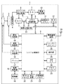
本実施の形態では、デジタルカメラとプリンタ間のアドホック接続による無線通信確立要求時の動作について説明する。図1は、本実施の形態におけるデジタルカメラのブロック構成例を示す図である。以下、本実施の形態におけるデジタルカメラの構成について説明する。 In this embodiment, an operation at the time of requesting establishment of wireless communication by ad hoc connection between a digital camera and a printer will be described. FIG. 1 is a diagram illustrating a block configuration example of a digital camera according to the present embodiment. Hereinafter, the configuration of the digital camera in this embodiment will be described.
1は本実施の形態で用いられるデジタルカメラである。2は撮影レンズ、3は絞り機能を備えるシャッター、4は光学像を電気信号に変換する撮像素子、5は撮像素子4のアナログ信号出力をデジタル信号に変換するA/D変換器である。 Reference numeral 1 denotes a digital camera used in the present embodiment. Reference numeral 2 denotes a photographing lens, 3 denotes a shutter having a diaphragm function, 4 denotes an image sensor that converts an optical image into an electric signal, and 5 denotes an A / D converter that converts an analog signal output from the image sensor 4 into a digital signal.
6は撮像素子4、A/D変換器5、D/A変換器7にクロック信号や制御信号を供給するタイミング発生回路であり、メモリ制御回路8及びシステム制御回路9により制御される。10は画像処理回路であり、A/D変換器5からのデータあるいはメモリ制御回路8からのデータに対して所定の画素補間処理や色変換処理を行う。
A
8はメモリ制御回路であり、A/D変換器5、タイミング発生回路6、画像処理回路10、画像表示メモリ11、D/A変換器7及び第1のメモリ12を制御する。A/D変換器5のデータが画像処理回路10、メモリ制御回路8を介して、あるいはA/D変換器5のデータが直接メモリ制御回路8を介して、画像表示メモリ11あるいは第1のメモリ12に書き込まれる。
A memory control circuit 8 controls the A / D converter 5, the
11は画像表示メモリであり、7はD/A変換器である。13はTFT、LCD等から成る画像表示部であり、画像表示メモリ11に書き込まれた表示用の画像データはD/A変換器7を介して画像表示部13により表示される。画像表示部13を用いて撮像した画像データを逐次表示すれば、電子ファインダー機能を実現することが可能である。
11 is an image display memory, and 7 is a D / A converter.
12は撮影した静止画像や動画像を格納するための第1のメモリであり、所定枚数の静止画像や所定時間の動画像を格納するのに十分な記憶量を備えている。14は絞り機能を備えるシャッター3を制御する露光制御部であり、フラッシュ17と連携することによりフラッシュ調光機能も有するものである。
15は撮影レンズ2のフォーカシングを制御する測距制御部であり、16は撮影レンズ2のズーミングを制御するズーム制御部である。17はフラッシュであり、AF補助光の投光機能、フラッシュ調光機能も有する。9はデジタルカメラ1全体を制御するシステム制御回路、20はシステム制御回路9の動作用の定数、変数、プログラム等を記憶する第2のメモリである。
18は電源制御部で、電池検出回路、DC−DCコンバータ、通電するブロックを切り替えるスイッチ回路等により構成されており、電池の装着の有無、電池の種類、電池残量の検出を行い、検出結果及びシステム制御回路9の指示に基づいてDC−DCコンバータを制御し、必要な電圧を必要な期間、記録媒体を含む各部へ供給する。19はアルカリ電池やリチウム電池等の一次電池やNiCd電池やNiMH電池、Li電池等の二次電池、ACアダプター等からなる電源部である。
21はシステム制御回路9でのプログラムの実行に応じて、文字、画像、音声等を用いて動作状態やメッセージ等を表示する液晶表示装置、スピーカー等の表示装置であり、デジタルカメラ1の操作部近辺の視認し易い位置に単数あるいは複数個所設置され、例えばLCDやLED、発音素子等の組み合わせにより構成されている。
22は電気的に消去・記録可能な不揮発性メモリである。ここに機器の無線設定情報を記憶することができる。23はメモリカードを接続するためのメモリカードインタフェース(メモリカードI/F)であり、24は外部機器とUSBを用いて接続するためのUSBインタフェース(USB・I/F)である。
25は、システム制御回路9の各種の動作指示を入力するための操作部であり、スイッチやダイアル、タッチパネル、視線検知によるポインティング、音声認識装置等の単数あるいは複数の組み合わせで構成される。
26はシャッタースイッチで、撮像素子4から読み出した信号をA/D変換器5、メモリ制御回路8を介して第1のメモリ12に画像データを書き込む露光処理、画像処理回路10やメモリ制御回路8での演算を用いた現像処理という一連の処理の動作開始を指示する。27は無線通信回路であり、無線信号を送受信し、無線通信を制御する。28は他の機器と無線通信を行うためのアンテナである。
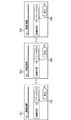
図2は、本実施の形態におけるプリンタの構成例を示す図である。以下、本発明の実施の形態におけるプリンタの構成について説明する。
図2において、201は本実施の形態で用いられるプリンタである。202は実際に用紙に画像をプリントするプリントエンジンであり、給紙部213から用紙を供給し、プリント処理部205によってデータ印刷処理を行い、排紙部214からプリントされた用紙を排紙する。
FIG. 2 is a diagram illustrating a configuration example of a printer according to the present embodiment. The configuration of the printer in the embodiment of the present invention will be described below.
In FIG. 2,
203はLCD表示、LED表示などでユーザに対する情報を表示する表示部であり、表示処理部206によって処理される。204はプリンタの操作部であり、システムコントローラ207を介してスイッチやダイアル、タッチパネル、視線検知によるポインティング、音声認識装置等の単数あるいは複数の組み合わせで構成される各種の動作指示を入力するための操作手段である。
Reference numeral 203 denotes a display unit that displays information for the user by LCD display, LED display, and the like, and is processed by the
208は電気的に消去・記録可能な不揮発性メモリである。ここに機器の無線設定情報を記憶することができる。209はプリンタの動作用の定数、変数、プログラム等を記憶するメモリである。
210は無線通信回路であり、無線信号を送受信し、無線通信を制御する。215は他の機器と無線通信を行うためのアンテナである。211は外部機器とUSBを用いて接続するためのUSBインタフェース(USB・I/F)であり、212はパーソナルコンピュータ等の外部機器とパラレル通信を用いて接続するためのパラレルインタフェース(パラレルI/F)である。
以下、これらのデジタルカメラとプリンタの構成をもとに、本実施の形態においてデジタルカメラ1とプリンタ201との間で無線接続が要求された場合の動作について説明する。
The operation when a wireless connection is requested between the digital camera 1 and the
既に前述したとおり、機器間で無線通信を行う場合の各種無線通信パラメータなどの設定は非常に煩雑な操作であるため、機器間の無線通信では、決まった通信相手機器に対してそれぞれの機器間で共通の、固有な無線設定情報を予め設定しておくのが自然であると考えられる。 As described above, setting various wireless communication parameters when performing wireless communication between devices is a very complicated operation, so in wireless communication between devices, between each device with respect to a fixed communication partner device. It is considered natural to set unique and unique wireless setting information in advance.
本実施の形態においてもデジタルカメラ1とプリンタ201との間で、予め無線設定情報が登録されており、両機器はユーザから無線通信を指示された場合にその無線設定情報に基づいて無線接続を試みる。
Also in this embodiment, wireless setting information is registered in advance between the digital camera 1 and the
図5は、本実施の形態におけるデジタルカメラ1とプリンタ201との間の無線接続が確立するまでのデジタルカメラ1の動作手順を示すフローチャートである。以下、フローチャートに基づいて説明する。
FIG. 5 is a flowchart showing an operation procedure of the digital camera 1 until the wireless connection between the digital camera 1 and the
図5において、まず、デジタルカメラ1で無線通信を行う操作がなされたことを検出した場合、デジタルカメラ1に無線通信相手との無線設定情報が登録されているか確認する(ステップS501)。この確認の結果、無線設定情報が登録されていなければ、図6に示すような警告表示画面601において「無線設定情報が登録されていません」等の警告表示602を行い(ステップS502)、本処理を終了する。また、ステップS501の確認の結果、無線設定情報が既に登録されている場合は、無線通信相手の選択画面を表示する(ステップS503)。
In FIG. 5, first, when it is detected that an operation for performing wireless communication is performed with the digital camera 1, it is confirmed whether or not wireless setting information with a wireless communication partner is registered in the digital camera 1 (step S501). If the wireless setting information is not registered as a result of the confirmation, a
図7は本実施の形態における無線通信相手を表示する一例を示す図である。
図7において、表示画面701では既に無線設定情報が登録されている「プリンタA」が無線通信相手として接続対象表示エリアに表示している接続相手702に表示されていることを示す。デジタルカメラ1が複数の無線通信相手の無線設定情報を保持している場合は、デジタルカメラ1の操作部25を使用して順送りで複数の接続候補を表示することができる。表示画面701で操作部25の十字キーを押下すると表示画面703おける接続対象表示エリアに無線通信相手704として「プリンタB」が表示される。また、さらに操作部25の十字キーを押下すると表示画面705が表示され、接続対象表示エリアには無線通信相手706として「プリンタC」が表示される。
FIG. 7 is a diagram showing an example of displaying a wireless communication partner in the present embodiment.
In FIG. 7, the display screen 701 indicates that “printer A” for which wireless setting information has already been registered is displayed on the
本実施の形態においては、デジタルカメラ1とプリンタ201の両機器に同じ無線設定情報が設定されているものとする。無線設定情報の内容としては、ネットワーク識別情報(SSID)や周波数(チャネル)が登録されており、各々の無線通信について固有のネットワーク識別情報を用いている。
In the present embodiment, it is assumed that the same wireless setting information is set in both the digital camera 1 and the
ここで、デジタルカメラ1が本実施の形態において接続しようとするプリンタ201の名称が「プリンタB」であるものとして以下説明する。
次に、ユーザはデジタルカメラ1より、表示画面703のように無線通信相手として「プリンタB」を選択する。すると、「プリンタB」が選択されたことに応じて、デジタルカメラ1で保持しているプリンタ201との無線設定情報を読み出して取得し(ステップS504)、任意の検索タイマ値を設定してから(ステップS505)、ビーコン信号のスキャニング動作を行う。
Here, the following description will be made assuming that the name of the
Next, the user selects “printer B” as the wireless communication partner from the digital camera 1 as shown in the
ここで、ビーコン信号のスキャニング動作について説明する。無線通信においては、通信に必要な情報を周辺の機器へ報知するためにビーコン信号が用いられ、通信の同期処理などを行っている。また、無線端末が無線ネットワークの検索を行う機能をスキャニングと呼び、スキャニングにはパッシブ・スキャニングとアクティブ・スキャニングの2種類がある。 Here, the scanning operation of the beacon signal will be described. In wireless communication, a beacon signal is used to notify peripheral devices of information necessary for communication, and communication synchronization processing is performed. The function of a wireless terminal searching for a wireless network is called scanning, and there are two types of scanning: passive scanning and active scanning.
本実施の形態では、ビーコン信号の受信を行う際にパッシブ・スキャニングと呼ばれている手法を用いる場合について説明する。デジタルカメラ1は予め設定されているプリンタ201との無線設定情報に従って、設定されたチャネルにおいてビーコン信号を監視しており、プリンタ201からビーコン信号が発信された場合には受信する。ここで、ビーコン信号を受信した場合は、ビーコン信号に設定されているネットワーク識別情報を調べて、プリンタ201との無線設定情報で設定されているネットワーク識別情報と一致するか判断する。このネットワーク識別情報が一致した場合、ビーコンが発見できたと判断して、「接続ボタン」を表示する。この接続ボタンは、適切なビーコンが検出されるまでは、グレーアウトして選択不可能状態に表示するようにしてもよい。
In the present embodiment, a case where a method called passive scanning is used when receiving a beacon signal will be described. The digital camera 1 monitors the beacon signal in the set channel according to the wireless setting information with the
なお、アクティブ・スキャニングと呼ばれている手法を用いる場合は、デジタルカメラ1は予め設定されているプリンタ201との無線設定情報を用いて、設定されたチャネルに対してProbe(調査)要求と呼ばれるフレームを送出する。Probe要求の中身には予め設定されたプリンタ201との無線設定情報のネットワーク識別情報が設定されている。その後、プリンタ201からProbe応答と呼ばれるフレームを受信する。このProbe応答のフレーム受信をもって、ビーコン信号が発見できたと判断する。本実施の形態において、どちらのスキャニング手法を用いても本提案の機能が実現可能であることをここに明示しておく。
When a method called active scanning is used, the digital camera 1 uses a wireless setting information with a
本実施の形態では、接続相手選択画面において接続相手を表示させたことをトリガとして、その接続相手との無線設定情報であるネットワーク識別情報やチャネルなどの情報を使ってビーコン信号の受信動作を行い、ユーザに対して無線接続の可否を迅速に知らせるようにしている。以下に、これを可能にする処理手順を説明する。 In this embodiment, triggered by the display of the connection partner on the connection partner selection screen, a beacon signal reception operation is performed using information such as network identification information and channel that is wireless setting information with the connection partner. The user is quickly informed of whether or not wireless connection is possible. In the following, a procedure for enabling this will be described.
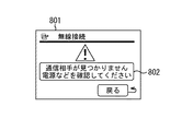
まず、検索タイマが終了したかどうかを確認する(ステップS506)。この確認の結果、終了していた場合は接続相手機器が発見されなかったため、図8に示すような警告表示画面801において「通信相手が見つかりません。電源などを確認してください。」等の警告表示802を行い(ステップS502)、ビーコン信号が発見されなかったことから接続相手機器の電源が入っていなかったり、無線通信が可能な状態になっていなかったりすることが原因であることを警告表示して、本処理を終了する。
First, it is confirmed whether the search timer has expired (step S506). As a result of the confirmation, since the connection partner device was not found when the process was completed, a
また、ステップS506の確認の結果、検索タイマが終了していなかったら、次に、接続相手選択画面において表示させている接続相手の変更があるかどうかの確認を行う(ステップS507)。この確認の結果、接続相手の変更があった場合はステップS503の処理に戻り、同様の動作を繰り返す。ステップS507の確認の結果、接続相手の変更が無かった場合には、前述のスキャニング手法を用いてビーコン信号の受信動作を行う(ステップS508)。 If the search timer has not expired as a result of the confirmation in step S506, it is next confirmed whether or not there is a change in the connection partner displayed on the connection partner selection screen (step S507). If there is a change in the connection partner as a result of this confirmation, the process returns to step S503 and the same operation is repeated. If there is no change in the connection partner as a result of the confirmation in step S507, a beacon signal reception operation is performed using the above-described scanning technique (step S508).
次に、無線設定情報に登録されたネットワーク識別情報のビーコン信号を受信したかどうかの判断を行う(ステップS509)。この判断の結果、ビーコン信号が発見されなかった場合はステップS506に戻り、検索タイマが終了するまで処理を繰り返す。また、ステップS509の判断の結果、ビーコン信号が発見された場合は、ユーザに対して、接続可能である旨の表示等の通知動作を行う(ステップS510)。 Next, it is determined whether a beacon signal of network identification information registered in the wireless setting information has been received (step S509). If no beacon signal is found as a result of this determination, the process returns to step S506, and the process is repeated until the search timer expires. If a beacon signal is found as a result of the determination in step S509, a notification operation such as a display indicating that connection is possible is performed to the user (step S510).
図9は、本実施の形態における「プリンタB」のビーコン信号が発見された時のユーザに対して表示する表示画面の一例を示す図である。ここまでの処理において、ビーコン信号を発見できたことで、アドホック接続においてデジタルカメラ1とプリンタ201との通信レイヤにおける物理層までの接続が確立されたことになる。そして、ユーザに対してプリンタ201との無線設定情報で登録されているネットワーク識別情報の無線ネットワークが存在していることを知らせ、さらに通信レイヤの上位層の接続の確立動作へ進むことが可能であることを、接続相手選択画面901に接続ボタン903を表示することでユーザに通知する。
FIG. 9 is a diagram showing an example of a display screen displayed to the user when the “printer B” beacon signal is found in the present embodiment. In the processing so far, the discovery of the beacon signal has established the connection to the physical layer in the communication layer between the digital camera 1 and the
ここで、接続相手選択画面901における接続対象表示エリアに表示している接続相手902に変更があるかどうかの確認を行う(ステップS511)。この確認の結果、選択機器が変更された場合はステップS503の処理に戻り、同様の動作を新しく選択された機器に対して繰り返す。
Here, it is confirmed whether or not there is a change in the
また、ステップS511の確認の結果、選択機器の変更がなければ、接続指示があるかどうか(図9における接続ボタン903が押下されたかどうか)を判断する。この判断の結果、接続指示があった場合(図9における接続ボタン903が押下された場合)は、プリンタ201との無線接続の確立を試み、接続が確立されると無線通信によるデータの送受信や印刷動作などが行われ(ステップS513)、処理を終了する。また、ステップS512の判断の結果、接続指示がない場合(接続ボタン903が押下されない場合)は、ステップS508の処理に戻り、ユーザに対する通知動作を繰り返す。
As a result of the confirmation in step S511, if there is no change in the selected device, it is determined whether there is a connection instruction (whether the
図10は、デジタルカメラ1とプリンタ201との間の無線接続が確立するまでのプリンタ201の動作手順の一例を示すフローチャートである。以下、フローチャートに基づいて説明する。
FIG. 10 is a flowchart illustrating an example of an operation procedure of the
図10において、プリンタ201の電源が入れられると、プリンタ201で無線設定情報が登録されているかどうかを確認する(ステップS1001)。この確認の結果、無線設定情報が登録されていない場合は、表示部203に無線設定がされていないことを示す警告表示を行い(ステップS1002)、本処理を終了する。
In FIG. 10, when the
また、ステップS1001の確認の結果、無線設定情報が登録されている場合は、その設定情報に基づいてビーコン信号の送信を開始する(ステップS1003)。具体的には、無線設定情報で登録されているチャネルに対して、同じく登録されているネットワーク識別情報をビーコン信号の中身に設定して送信する。 If wireless setting information is registered as a result of the confirmation in step S1001, transmission of a beacon signal is started based on the setting information (step S1003). More specifically, the registered network identification information is set in the contents of the beacon signal and transmitted to the channel registered in the wireless setting information.
本実施の形態では、デジタルカメラ1が前述のアクティブ・スキャニング動作を行った場合について説明する。次に、Probe要求フレームを受信したかどうかを判断する(ステップS1004)。この判断の結果、受信したならば、Probe要求フレームに設定されているネットワーク識別情報を調べて、プリンタ201に設定されているネットワーク識別情報と一致する場合はProbe応答フレームを返信する(ステップS1005)。
In the present embodiment, a case where the digital camera 1 performs the above-described active scanning operation will be described. Next, it is determined whether a Probe request frame has been received (step S1004). If it is received as a result of this determination, the network identification information set in the probe request frame is checked, and if it matches the network identification information set in the
その後、接続要求があるかどうかを判断する(ステップS1006)。この判断の結果、接続要求があれば、受信した接続要求に従って無線接続を行う(ステップS1007)。また、ステップS1006の判断の結果、接続要求がなければ、ステップS1004の処理へ戻る。 Thereafter, it is determined whether or not there is a connection request (step S1006). If there is a connection request as a result of this determination, wireless connection is performed according to the received connection request (step S1007). If the result of determination in step S1006 is that there is no connection request, processing returns to step S1004.
なお、本実施の形態において、デジタルカメラ1とプリンタ201との間の無線通信を実現する際には双方の機器ともアドホック接続で接続することが望ましい。これは、デジタルカメラ1とプリンタ201とでインフラ接続によって接続するようにした場合には、基地局となるアクセスポイントがビーコン信号を発信する。このため、通信相手となるプリンタ201が無線通信が不可の状態においても、アクセスポイントから発信されるビーコン信号をデジタルカメラ1で受信することにより、登録されたネットワーク識別情報の無線ネットワークが存在することを表示してしまうので、プリンタ201との無線接続が可能であるとユーザに対して誤解させてしまうことも考えられるからである。
In the present embodiment, when realizing wireless communication between the digital camera 1 and the
また、各線通信機器との無線設定情報についてネットワーク識別情報などを固有のものに設定することが望ましい。ビーコン信号に設定されたネットワーク識別情報が固有な情報となることで物理層より上位の通信層で接続を行う際の通信相手の存在確率を高め、また機器間の通信が1対1で行われる確率を高めて、通信の秘匿性が高まるためである。 In addition, it is desirable to set the network identification information and the like unique to the wireless setting information with each line communication device. Since the network identification information set in the beacon signal becomes unique information, the existence probability of a communication partner when connecting in a communication layer higher than the physical layer is increased, and communication between devices is performed one-to-one. This is because the probability of communication is increased and the confidentiality of communication is increased.
以上のように、相手を選択するに際し、登録機器全ての通信状態を調査するのは、時間も電力も掛かる。また、せっかく選択した相手が、周りにいなくて通信できないような操作形態だと、使いづらいし、通信可能までの時間が掛かる。 As described above, it takes time and power to investigate the communication status of all registered devices when selecting a partner. Also, if the selected partner is in an operation mode in which communication is impossible without being around, it is difficult to use and it takes time until communication is possible.
これに対して、前記の構成によれば、接続相手を選択したことに応じて、その相手からのビーコンを待ち受けるようになるので、自然な操作感で相手を選択し、その存在を確認できる。さらに、ビーコン待ち受けタイミングを限定することで、通信の電力消費を少なくできる。 On the other hand, according to the above configuration, in response to the selection of a connection partner, a beacon from that partner is awaited. Therefore, the partner can be selected with a natural feeling of operation, and its existence can be confirmed. Furthermore, the power consumption of communication can be reduced by limiting the beacon standby timing.
(第2の実施の形態)
次に、第2の実施の形態を説明する。本実施の形態では第1の実施の形態と同様に、図1及び図2に示したようなハード構成のデジタルカメラ1とプリンタ201との間のアドホック接続による無線通信確立要求時に行われる動作について説明する。本実施の形態では、ユーザに対して通信相手機器との無線通信の可否を通知する際に、無線通信における通信品質について表示する点が第1の実施の形態と異なる。
(Second Embodiment)
Next, a second embodiment will be described. In the present embodiment, as in the first embodiment, an operation performed when a wireless communication establishment request is made by ad hoc connection between the digital camera 1 having a hardware configuration as shown in FIGS. 1 and 2 and the
図11は、本実施の形態において、デジタルカメラ1とプリンタ201との間の無線接続が確立するまでのデジタルカメラ1の動作手順の一例を示すフローチャートである。以下、図11のフローチャートに基づいて説明する。
FIG. 11 is a flowchart illustrating an example of an operation procedure of the digital camera 1 until wireless connection between the digital camera 1 and the
まず、デジタルカメラ1で無線通信を行う操作がなされたことを検出した場合、デジタルカメラ1に無線通信相手との無線設定情報が登録されているかどうかを確認する(ステップS1101)。この確認の結果、無線設定情報が登録されていない場合は、図6に示すような警告表示画面601において「無線設定情報が登録されていません」等の警告表示を行い(ステップS1102)、本処理を終了する。
First, when it is detected that an operation for performing wireless communication with the digital camera 1 is detected, it is confirmed whether or not wireless setting information with a wireless communication partner is registered in the digital camera 1 (step S1101). If the wireless setting information is not registered as a result of the confirmation, a warning display such as “Wireless setting information is not registered” is displayed on the
ステップS1101の確認の結果、無線設定情報が既に登録されている場合は、無線通信相手の選択画面を表示する(ステップ1103)。図7において、表示画面701では既に無線設定情報が登録されている「プリンタA」が無線通信相手702として接続対象表示エリアに表示されていることを示す。デジタルカメラ1が複数の無線通信相手の無線設定情報を保持している場合はデジタルカメラ1の操作部を使用して順送りで複数の接続候補を表示することができる。
If the wireless setting information has already been registered as a result of the confirmation in step S1101, a wireless communication partner selection screen is displayed (step 1103). In FIG. 7, the display screen 701 indicates that “printer A” for which wireless setting information has already been registered is displayed in the connection target display area as the
表示画面701で操作部の十字キーを押下すると表示画面703が表示され、接続対象表示エリアに無線通信相手704として「プリンタB」が表示される。また、さらに操作部の十字キーを押下すると表示画面705が表示され、接続対象表示エリアに無線通信相手706として「プリンタC」が表示される。
When the cross key on the operation unit is pressed on the display screen 701, the
本実施の形態においてデジタルカメラ1およびプリンタ201では両機器に同じ無線設定情報が設定されているものとする。無線設定情報の内容としては、ネットワーク識別情報(SSID)や周波数(チャネル)が登録されており、各々の無線通信について固有のネットワーク識別情報を用いている。
In the present embodiment, it is assumed that the same wireless setting information is set in both devices in the digital camera 1 and the
ここで、デジタルカメラ1が本実施の形態において接続するプリンタ201の名称が「プリンタB」であるとして以下説明する。ユーザはデジタルカメラ1より、図7の通信相手選択画面703のように無線通信相手として「プリンタB」を選択する。すると、「プリンタB」が選択されたことに応じて、デジタルカメラ1で保持しているプリンタ201との無線設定情報を読み出し(ステップS1104)、任意のタイマ値を設定して(ステップS1105)、ビーコン信号のスキャニング動作を行う。スキャニング動作については前述したパッシブ・スキャニングまたはアクティブ・スキャニングを行う。
Here, the following description will be made assuming that the name of the
本実施の形態では、接続相手選択画面において接続相手を表示させたことをトリガとして、その接続相手との無線設定情報であるネットワーク識別情報やチャネルなどの情報を使ってビーコン信号の受信動作を行い、ユーザに対して無線接続の可否を知らせ、さらにその通信相手との通信の品質をユーザに通知する。 In this embodiment, triggered by the display of the connection partner on the connection partner selection screen, a beacon signal reception operation is performed using information such as network identification information and channel that is wireless setting information with the connection partner. The user is notified of whether or not wireless connection is possible, and the user is notified of the quality of communication with the communication partner.
次に、検索タイマが終了したかどうかを確認する(ステップS1106)。この確認の結果、終了していた場合は接続相手機器が発見されなかったため、図8に示すような警告表示画面801において「通信相手が見つかりません。電源などを確認してください。」等の警告表示802を行い(ステップS1102)、ビーコン信号が発見されなかったことが接続相手機器の電源が入っていなかったり、無線通信が可能な状態になっていなかったりすることが原因であることを警告表示して本処理を終了する。
Next, it is confirmed whether or not the search timer has expired (step S1106). As a result of the confirmation, since the connection partner device was not found when the process was completed, a
また、ステップS1106の確認の結果、検索タイマが終了していなければ、次に、接続相手選択画面において表示させている接続相手の変更があるかどうかの確認を行う(ステップS1107)。この確認の結果、接続相手の変更があった場合はステップS1103の処理に戻り、同様の動作を繰り返す。 If the search timer has not expired as a result of the confirmation in step S1106, it is next confirmed whether or not there is a change in the connection partner displayed on the connection partner selection screen (step S1107). If there is a change in the connection partner as a result of this confirmation, the process returns to step S1103 and the same operation is repeated.
また、ステップS1107の確認の結果、接続相手の変更が無かった場合には、前述のスキャニング手段を用いてビーコン信号の受信動作を行う(ステップS1108)。次に、無線設定情報に登録されたネットワーク識別情報のビーコン信号を受信したかの判断を行う(ステップS1109)。この判断の結果、ビーコン信号が発見されなかった場合はステップS1106の処理に戻り、検索タイマが終了するまで処理を繰り返す。 If there is no change in the connection partner as a result of the confirmation in step S1107, a beacon signal reception operation is performed using the above-described scanning means (step S1108). Next, it is determined whether the beacon signal of the network identification information registered in the wireless setting information has been received (step S1109). If no beacon signal is found as a result of this determination, the process returns to step S1106, and the process is repeated until the search timer expires.
また、ステップS1109の判断の結果、ビーコン信号が発見された場合は、そのビーコン信号からSN比(Signal to Noise ratio)を算出することによって前記ビーコン信号の品質測定を行い(ステップS1110)、通信相手との通信信号の品質をユーザに通知する。SN比は通信信号と雑音との比であり、数値が大きいほどその信号がノイズの少ない良好な信号であることを示す。 If a beacon signal is found as a result of the determination in step S1109, the beacon signal quality is measured by calculating an SN ratio (Signal to Noise ratio) from the beacon signal (step S1110). The communication signal quality is notified to the user. The S / N ratio is a ratio between a communication signal and noise. A larger value indicates that the signal is a better signal with less noise.
ここで算出されたSN比を用いて最低限の通信が行えると思われる閾値と比較する(ステップS1111)。この比較の結果、SN比が閾値よりも低い場合は図12に示すように警告画面1201において通信品質表示1202とともにユーザに対して良好な通信が困難である旨を通知し(ステップS1102)、通信機器同士の距離を狭めたりするなどの解決策を画面1203に表示し、本処理を終了する。また、ステップS1111の比較の結果、SN比が閾値よりも高い場合には、ユーザに対して通信品質などの表示動作を行う(ステップS1112)。
The signal-to-noise ratio calculated here is compared with a threshold that is considered to allow minimum communication (step S1111). If the S / N ratio is lower than the threshold value as a result of this comparison, a
図13は、本実施の形態における「プリンタB」のビーコン信号が発見された時のユーザに対して表示する表示画面の一例を示す図である。ここまでの処理においてビーコン信号が発見できたことで、アドホック接続においてデジタルカメラ1とプリンタ201との通信レイヤにおける物理層までの接続が確立されたことになる。そして、ユーザに対してプリンタ201との無線設定情報で登録されているネットワーク識別情報の無線ネットワークが存在していることを知らせ、さらに上位層の接続の確立が可能であることを接続ボタン1304を表示することでユーザに通知する。また、通信品質の通知をユーザに対して行う。通信品質表示1302では表示されている右側の棒の本数によって段階的に通信品質をユーザに通知している。一方、通信品質が悪く、通信相手との接続の確立が不可能である場合は、前記接続ボタン1304は表示されない。
FIG. 13 is a diagram showing an example of a display screen displayed to the user when the “printer B” beacon signal is found in the present embodiment. Since the beacon signal has been found in the process so far, the connection to the physical layer in the communication layer between the digital camera 1 and the
ユーザはこの表示により通信品質が悪いと感じる場合には、無線接続を確立する以前の段階で、通信距離を狭めたり、無線通信の障害物を取り除いたりなどして無線接続が確立する可能性を高め、信頼性のある通信を行うことができるようになる。 If the user feels that the communication quality is poor due to this display, there is a possibility that the wireless connection will be established by shortening the communication distance or removing obstacles in the wireless communication before establishing the wireless connection. It becomes possible to perform communication with higher reliability.
次に、通信している選択機器の変更があるかどうか確認を行う(ステップS1113)。この確認の結果、選択機器の変更があるならば、ステップS1103の処理に戻り、同様の動作を新しく選択された機器に対して繰り返す。 Next, it is confirmed whether there is a change in the selected device that is communicating (step S1113). If the selected device is changed as a result of the confirmation, the process returns to step S1103, and the same operation is repeated for the newly selected device.
例えば、デジタルカメラ1が複数の通信相手に対する無線設定情報を登録しているような場合は、プリンタ201との通信品質が悪いと感じたときに、選択している通信相手機器を変更し、ステップS1103の処理に戻って別の機器を選択し、一連の動作を繰り返すことでより良好な通信を行える機器を発見することができる。これにより、無線接続が行える可能性の高い通信相手機器の選択が無線接続を確立する以前の段階で迅速に行えるため、ユーザにとって接続相手を選択する際の時間の負荷を減らすことができる。
For example, when the digital camera 1 registers wireless setting information for a plurality of communication partners, when the communication quality with the
また、ステップS1113の確認の結果、選択機器の変更がなければ、接続指示があるかどうか(図13における接続ボタン1304が押下されたかどうか)を判断する(ステップS1114)。この判断の結果、接続指示があった場合(図13におけるユーザに対する通知画面1301で接続ボタン1304が押下された場合)は、プリンタ201との無線接続の確立を試み、接続が確立される(ステップS1115)。そして、無線通信によるデータの送受信や印刷動作などが行われ、処理を終了する。
If the selected device is not changed as a result of the confirmation in step S1113, it is determined whether there is a connection instruction (whether the
また、ステップS1114の判断の結果、接続指示がない場合(接続ボタン1304が押下されない場合)は、ステップS1109の処理に戻り、ユーザに対する通知動作を繰り返す。
If there is no connection instruction as a result of the determination in step S1114 (when the
また、プリンタ201の動作については第1の実施の形態と同様であるため、説明は省略する。
Since the operation of the
なお、本実施の形態においても第1の実施の形態と同様に、無線接続をアドホック接続で行い、各線通信機器との無線設定情報についてネットワーク識別情報などを固有のものに設定することが望ましい。所望のネットワーク識別情報を設定したビーコン信号を送出する機器が無線接続相手の機器である可能性を高めることで、物理層より上位の通信層で接続を行う際の通信相手の存在確率を高め、ビーコン信号から算出されるSN比による通信品質が通信相手機器との直接の通信における品質であることを示すことになるためである。 In this embodiment as well, as in the first embodiment, it is desirable to perform wireless connection by ad hoc connection and to set unique network identification information and the like for wireless setting information with each line communication device. By increasing the possibility that the device that transmits the beacon signal in which the desired network identification information is set is the device of the wireless connection partner, the existence probability of the communication partner when making a connection in the communication layer higher than the physical layer is increased, This is because the communication quality based on the S / N ratio calculated from the beacon signal indicates that the communication quality is a direct communication quality with a communication partner device.
(本発明に係る他の実施の形態)
前述した本発明の実施の形態における無線通信装置を構成する各手段、並びに無線通信方法の各ステップは、コンピュータのRAMやROMなどに記憶されたプログラムが動作することによって実現できる。このプログラム及び前記プログラムを記録したコンピュータ読み取り可能な記録媒体は本発明に含まれる。
(Another embodiment according to the present invention)
Each means constituting the wireless communication apparatus and each step of the wireless communication method in the embodiment of the present invention described above can be realized by operating a program stored in a RAM or ROM of a computer. This program and a computer-readable recording medium recording the program are included in the present invention.
また、本発明は、例えば、システム、装置、方法、プログラムもしくは記録媒体等としての実施の形態も可能であり、具体的には、複数の機器から構成されるシステムに適用してもよいし、また、一つの機器からなる装置に適用してもよい。 Further, the present invention can be implemented as, for example, a system, apparatus, method, program, or recording medium, and can be applied to a system composed of a plurality of devices. Moreover, you may apply to the apparatus which consists of one apparatus.
なお、本発明は、前述した実施の形態の機能を実現するソフトウェアのプログラム(実施の形態では図5、図10、図11に示すフローチャートに対応したプログラム)を、システムあるいは装置に直接、あるいは遠隔から供給し、そのシステムあるいは装置のコンピュータが前記供給されたプログラムコードを読み出して実行することによっても達成される場合を含む。 In the present invention, a software program (in the embodiment, a program corresponding to the flowcharts shown in FIGS. 5, 10, and 11) that realizes the functions of the above-described embodiments is directly or remotely transmitted to a system or apparatus. And the case where the computer of the system or apparatus reads out and executes the supplied program code.
したがって、本発明の機能処理をコンピュータで実現するために、前記コンピュータにインストールされるプログラムコード自体も本発明を実現するものである。つまり、本発明は、本発明の機能処理を実現するためのコンピュータプログラム自体も含まれる。 Accordingly, since the functions of the present invention are implemented by computer, the program code installed in the computer also implements the present invention. In other words, the present invention includes a computer program itself for realizing the functional processing of the present invention.
その場合、プログラムの機能を有していれば、オブジェクトコード、インタプリタにより実行されるプログラム、OSに供給するスクリプトデータ等の形態であってもよい。 In that case, as long as it has the function of a program, it may be in the form of object code, a program executed by an interpreter, script data supplied to the OS, and the like.
プログラムを供給するための記録媒体としては、例えば、フロッピー(登録商標)ディスク、ハードディスク、光ディスク、光磁気ディスク、MO、CD−ROM、CD−R、CD−RW、磁気テープ、不揮発性のメモリカード、ROM、DVD(DVD−ROM、DVD−R)などがある。 As a recording medium for supplying the program, for example, floppy (registered trademark) disk, hard disk, optical disk, magneto-optical disk, MO, CD-ROM, CD-R, CD-RW, magnetic tape, nonvolatile memory card ROM, DVD (DVD-ROM, DVD-R) and the like.
その他、プログラムの供給方法としては、クライアントコンピュータのブラウザを用いてインターネットのホームページに接続し、前記ホームページから本発明のコンピュータプログラムそのもの、もしくは圧縮され自動インストール機能を含むファイルをハードディスク等の記録媒体にダウンロードすることによっても供給できる。 As another program supply method, a client computer browser is used to connect to an Internet homepage, and the computer program itself of the present invention or a compressed file including an automatic installation function is downloaded from the homepage to a recording medium such as a hard disk. Can also be supplied.
また、本発明のプログラムを構成するプログラムコードを複数のファイルに分割し、それぞれのファイルを異なるホームページからダウンロードすることによっても実現可能である。つまり、本発明の機能処理をコンピュータで実現するためのプログラムファイルを複数のユーザに対してダウンロードさせるWWWサーバも、本発明に含まれるものである。 It can also be realized by dividing the program code constituting the program of the present invention into a plurality of files and downloading each file from a different homepage. That is, a WWW server that allows a plurality of users to download a program file for realizing the functional processing of the present invention on a computer is also included in the present invention.
また、本発明のプログラムを暗号化してCD−ROM等の記録媒体に格納してユーザに配布し、所定の条件をクリアしたユーザに対し、インターネットを介してホームページから暗号化を解く鍵情報をダウンロードさせ、その鍵情報を使用することにより暗号化されたプログラムを実行してコンピュータにインストールさせて実現することも可能である。 In addition, the program of the present invention is encrypted, stored on a recording medium such as a CD-ROM, distributed to users, and key information for decryption is downloaded from a homepage via the Internet to users who have cleared predetermined conditions. It is also possible to execute the encrypted program by using the key information and install the program on a computer.
また、コンピュータが、読み出したプログラムを実行することによって、前述した実施の形態の機能が実現される他、そのプログラムの指示に基づき、コンピュータ上で稼動しているOSなどが、実際の処理の一部または全部を行い、その処理によっても前述した実施の形態の機能が実現され得る。 In addition to the functions of the above-described embodiments being realized by the computer executing the read program, the OS running on the computer based on the instructions of the program is used for the actual processing. The functions of the above-described embodiment can be realized by performing some or all of the processes.
さらに、記録媒体から読み出されたプログラムが、コンピュータに挿入された機能拡張ボードやコンピュータに接続された機能拡張ユニットに備わるメモリに書き込まれた後、そのプログラムの指示に基づき、その機能拡張ボードや機能拡張ユニットに備わるCPUなどが実際の処理の一部または全部を行い、その処理によっても前述した実施の形態の機能が実現される。 Furthermore, after the program read from the recording medium is written in a memory provided in a function expansion board inserted into the computer or a function expansion unit connected to the computer, the function expansion board or The CPU or the like provided in the function expansion unit performs part or all of the actual processing, and the functions of the above-described embodiments are realized by the processing.
1 デジタルカメラ
2 撮影レンズ
3 シャッター
4 撮像素子
5 A/D変換器
6 タイミング発生回路
7 D/A変換器
8 メモリ制御回路
9 システム制御回路
10 画像処理回路
11 画像表示メモリ
12 第1のメモリ
13 画像表示部
14 露光制御部
15 測距制御部
16 ズーム制御部
17 フラッシュ
18 電源制御部
19 電源部
20 第2のメモリ
21 表示装置
22 不揮発性メモリ
23 メモリカードI/F
24 USB・I/F
25 操作部
26 シャッタースイッチ
27 無線通信回路
28 アンテナ
201 プリンタ
202 プリントエンジン
203 表示部
204 操作部
205 プリント処理部
206 表示処理部
207 システムコントローラ
208 不揮発性メモリ
209 メモリ
210 無線通信回路
211 USB・I/F
212 パラレルI/F
213 給紙部
214 排紙部
215 アンテナ
DESCRIPTION OF SYMBOLS 1 Digital camera 2 Shooting lens 3 Shutter 4 Image sensor 5 A /
24 USB / I / F
25
212 Parallel I / F
213 Paper feed unit 214
Claims (17)
前記他の無線通信装置を示す情報及び無線設定情報を少なくとも1つ以上記憶部に記憶する記憶手段と、
前記記憶手段により前記記憶部に記憶された他の無線通信装置を示す情報を、選択可能に表示する表示手段と、
前記無線設定情報に従ってビーコン信号を検出する検出手段と、
前記検出手段の検出結果に基づいて、前記表示手段によって表示された情報に対応する前記他の無線通信装置が無線ネットワーク上に存在するかどうかを判断する判断手段とを有することを特徴とする無線通信装置。 A wireless communication device that constitutes a wireless communication system together with other wireless communication devices,
Storage means for storing at least one or more pieces of information and wireless setting information indicating the other wireless communication device;
Display means for selectively displaying information indicating other wireless communication devices stored in the storage unit by the storage means;
Detecting means for detecting a beacon signal according to the wireless setting information;
Wireless means comprising: a determination means for determining whether or not the other wireless communication device corresponding to the information displayed by the display means exists on a wireless network based on a detection result of the detection means; Communication device.
前記受理手段によって受理された無線接続要求に応じて、前記他の無線通信装置と無線接続処理を行う無線接続手段とを有することを特徴とする請求項1または2に記載の無線通信装置。 Receiving means for receiving a wireless connection request with the other wireless communication device;
The wireless communication device according to claim 1, further comprising: a wireless connection unit that performs wireless connection processing with the other wireless communication device in response to a wireless connection request received by the reception unit.
前記計算手段による計算の結果に応じて、前記他の無線通信装置との無線通信の信号品質を段階的に表示する信号品質表示手段とを有することを特徴とする請求項1〜4の何れか1項に記載の無線通信装置。 Calculating means for calculating signal quality from the beacon signal detected by the detecting means;
5. Signal quality display means for displaying signal quality of wireless communication with the other wireless communication apparatus in a stepwise manner according to a result of calculation by the calculating means. Item 1. A wireless communication device according to item 1.
前記表示手段は、前記中断手段で前記無線接続処理を中断した場合は、無線通信が不可であることを表示することを特徴とする請求項5に記載の無線通信装置。 As a result of calculation by the calculation means, when the signal quality is lower than a predetermined standard, there is an interruption means for interrupting the wireless connection process,
The wireless communication apparatus according to claim 5, wherein the display unit displays that wireless communication is impossible when the wireless connection process is interrupted by the interrupting unit.
前記検出手段は、前記選択手段で選択したことに応じて検出動作を開始することを特徴とする請求項1〜6の何れか1項に記載の無線通信装置。 Selecting means for selecting the other wireless communication device as a partner to start communication while referring to the display of the display means;
The wireless communication apparatus according to claim 1, wherein the detection unit starts a detection operation in response to selection by the selection unit.
前記検出手段は、前記選択手段で選択された他の無線通信装置に対応するビーコン信号の検出を行うことを特徴とする請求項1〜6の何れか1項に記載の無線通信装置。 Selecting means for selecting the other wireless communication device as a partner to start communication while referring to the display of the display means;
The wireless communication apparatus according to claim 1, wherein the detection unit detects a beacon signal corresponding to another wireless communication apparatus selected by the selection unit.
前記他の無線通信装置に関する無線設定情報を少なくとも1つ以上記憶部に記憶する無線設定情報記憶手段と、
前記無線設定情報記憶手段により前記記憶部に記憶された無線設定情報に基づいて、ビーコン信号を送信する送信手段とを有することを特徴とする無線通信装置。 A wireless communication device that constitutes a wireless communication system together with other wireless communication devices,
Wireless setting information storage means for storing at least one wireless setting information related to the other wireless communication device in a storage unit;
A wireless communication apparatus comprising: a transmission unit configured to transmit a beacon signal based on the wireless setting information stored in the storage unit by the wireless setting information storage unit.
前記他の無線通信装置を示す情報及び無線設定情報を少なくとも1つ以上記憶部に記憶する記憶工程と、
前記記憶工程により前記記憶部に記憶された他の無線通信装置を示す情報を、選択可能に表示する表示工程と、
前記無線設定情報に従ってビーコン信号を検出する検出工程と、
前記検出工程の検出結果に基づいて、前記表示工程によって表示された情報に対応する前記他の無線通信装置が無線ネットワーク上に存在するかどうかを判断する判断工程とを有することを特徴とする無線通信方法。 A wireless communication method in a wireless communication device that constitutes a wireless communication system together with another wireless communication device,
A storage step of storing at least one or more information indicating the other wireless communication device and wireless setting information in a storage unit;
A display step for selectively displaying information indicating other wireless communication devices stored in the storage unit by the storage step;
A detecting step of detecting a beacon signal according to the wireless setting information;
And a determination step of determining whether or not the other wireless communication device corresponding to the information displayed by the display step exists on a wireless network based on a detection result of the detection step. Communication method.
前記他の無線通信装置に関する無線設定情報を少なくとも1つ以上記憶部に記憶する無線設定情報記憶工程と、
前記無線設定情報記憶工程により前記記憶部に記憶された無線設定情報に基づいて、ビーコン信号を送信する送信工程とを有することを特徴とする無線通信方法。 A wireless communication method in a wireless communication device that constitutes a wireless communication system together with another wireless communication device,
A wireless setting information storage step of storing at least one wireless setting information related to the other wireless communication device in a storage unit;
And a transmitting step of transmitting a beacon signal based on the wireless setting information stored in the storage unit by the wireless setting information storing step.
前記他の無線通信装置を示す情報及び無線設定情報を少なくとも1つ以上記憶部に記憶する記憶工程と、
前記記憶工程により前記記憶部に記憶された他の無線通信装置を示す情報を、選択可能に表示する表示工程と、
前記無線設定情報に従ってビーコン信号を検出する検出工程と、
前記検出工程の検出結果に基づいて、前記表示工程によって表示された情報に対応する前記他の無線通信装置が無線ネットワーク上に存在するかどうかを判断する判断工程とを有する無線通信方法をコンピュータに実行させることを特徴とするコンピュータプログラム。 A program for causing a computer to execute a wireless communication method in a wireless communication device that constitutes a wireless communication system together with another wireless communication device,
A storage step of storing at least one or more pieces of information and wireless setting information indicating the other wireless communication device;
A display step for selectively displaying information indicating other wireless communication devices stored in the storage unit by the storage step;
A detecting step of detecting a beacon signal according to the wireless setting information;
A wireless communication method comprising: a determination step of determining whether or not the other wireless communication device corresponding to the information displayed in the display step exists on a wireless network based on a detection result of the detection step; A computer program that is executed.
前記他の無線通信装置に関する無線設定情報を少なくとも1つ以上記憶部に記憶する無線設定情報記憶工程と、
前記無線設定情報記憶工程により前記記憶部に記憶された無線設定情報に基づいて、ビーコン信号を送信する送信工程とを有する無線通信方法をコンピュータに実行させることを特徴とするコンピュータプログラム。 A program for causing a computer to execute a wireless communication method in a wireless communication device that constitutes a wireless communication system together with another wireless communication device,
A wireless setting information storage step of storing at least one wireless setting information related to the other wireless communication device in a storage unit;
A computer program causing a computer to execute a wireless communication method including a transmission step of transmitting a beacon signal based on the wireless setting information stored in the storage unit by the wireless setting information storage step.
Priority Applications (1)
| Application Number | Priority Date | Filing Date | Title |
|---|---|---|---|
| JP2005207643A JP2007028219A (en) | 2005-07-15 | 2005-07-15 | Wireless communication device, wireless communication method, and wireless communication system |
Applications Claiming Priority (1)
| Application Number | Priority Date | Filing Date | Title |
|---|---|---|---|
| JP2005207643A JP2007028219A (en) | 2005-07-15 | 2005-07-15 | Wireless communication device, wireless communication method, and wireless communication system |
Related Child Applications (1)
| Application Number | Title | Priority Date | Filing Date |
|---|---|---|---|
| JP2011168225A Division JP5121988B2 (en) | 2011-08-01 | 2011-08-01 | Wireless communication device, wireless communication device control method, and program |
Publications (2)
| Publication Number | Publication Date |
|---|---|
| JP2007028219A true JP2007028219A (en) | 2007-02-01 |
| JP2007028219A5 JP2007028219A5 (en) | 2008-08-28 |
Family
ID=37788388
Family Applications (1)
| Application Number | Title | Priority Date | Filing Date |
|---|---|---|---|
| JP2005207643A Pending JP2007028219A (en) | 2005-07-15 | 2005-07-15 | Wireless communication device, wireless communication method, and wireless communication system |
Country Status (1)
| Country | Link |
|---|---|
| JP (1) | JP2007028219A (en) |
Cited By (7)
| Publication number | Priority date | Publication date | Assignee | Title |
|---|---|---|---|---|
| JP2007036979A (en) * | 2005-07-29 | 2007-02-08 | Ricoh Co Ltd | Image photographing apparatus |
| WO2008102434A1 (en) * | 2007-02-20 | 2008-08-28 | Panasonic Corporation | Communication terminal and image data transfer method |
| JP2009302649A (en) * | 2008-06-10 | 2009-12-24 | Canon Inc | Communication equipment, communication method of communication equipment, program, and storage medium |
| JP2014131225A (en) * | 2012-12-28 | 2014-07-10 | Canon Inc | Content transmission device, information processor, content transmission system, and control method for them |
| JP2014165593A (en) * | 2013-02-22 | 2014-09-08 | Canon Inc | Communication device, communication system, communication device control method and computer program |
| JP2021073776A (en) * | 2019-09-12 | 2021-05-13 | キヤノン株式会社 | Program and image forming apparatus |
| JP2021184628A (en) * | 2021-01-14 | 2021-12-02 | キヤノン株式会社 | Program and communication terminal |
Citations (3)
| Publication number | Priority date | Publication date | Assignee | Title |
|---|---|---|---|---|
| JP2004328288A (en) * | 2003-04-23 | 2004-11-18 | Canon Inc | Image pickup device, image processor, control method for them. and radio communication environment setting method |
| JP2004328269A (en) * | 2003-04-23 | 2004-11-18 | Canon Inc | Radio communication system, radio communication device, and control method therefor |
| JP2005033285A (en) * | 2003-07-08 | 2005-02-03 | Hitachi Ltd | Radio information terminal and radio communication system |
-
2005
- 2005-07-15 JP JP2005207643A patent/JP2007028219A/en active Pending
Patent Citations (3)
| Publication number | Priority date | Publication date | Assignee | Title |
|---|---|---|---|---|
| JP2004328288A (en) * | 2003-04-23 | 2004-11-18 | Canon Inc | Image pickup device, image processor, control method for them. and radio communication environment setting method |
| JP2004328269A (en) * | 2003-04-23 | 2004-11-18 | Canon Inc | Radio communication system, radio communication device, and control method therefor |
| JP2005033285A (en) * | 2003-07-08 | 2005-02-03 | Hitachi Ltd | Radio information terminal and radio communication system |
Cited By (10)
| Publication number | Priority date | Publication date | Assignee | Title |
|---|---|---|---|---|
| JP2007036979A (en) * | 2005-07-29 | 2007-02-08 | Ricoh Co Ltd | Image photographing apparatus |
| JP4570530B2 (en) * | 2005-07-29 | 2010-10-27 | 株式会社リコー | Image shooting device |
| WO2008102434A1 (en) * | 2007-02-20 | 2008-08-28 | Panasonic Corporation | Communication terminal and image data transfer method |
| JP4954272B2 (en) * | 2007-02-20 | 2012-06-13 | パナソニック株式会社 | Communication terminal device and image data transfer method |
| JP2009302649A (en) * | 2008-06-10 | 2009-12-24 | Canon Inc | Communication equipment, communication method of communication equipment, program, and storage medium |
| JP2014131225A (en) * | 2012-12-28 | 2014-07-10 | Canon Inc | Content transmission device, information processor, content transmission system, and control method for them |
| US9578202B2 (en) | 2012-12-28 | 2017-02-21 | Canon Kabushiki Kaisha | Communication apparatus and method of controlling communication apparatus |
| JP2014165593A (en) * | 2013-02-22 | 2014-09-08 | Canon Inc | Communication device, communication system, communication device control method and computer program |
| JP2021073776A (en) * | 2019-09-12 | 2021-05-13 | キヤノン株式会社 | Program and image forming apparatus |
| JP2021184628A (en) * | 2021-01-14 | 2021-12-02 | キヤノン株式会社 | Program and communication terminal |
Similar Documents
| Publication | Publication Date | Title |
|---|---|---|
| US8150449B2 (en) | Wireless communication device | |
| US11019477B2 (en) | Communication apparatus, method of controlling the same, and storage medium | |
| JP2007028219A (en) | Wireless communication device, wireless communication method, and wireless communication system | |
| JP2010011364A (en) | Image output system and method of controlling the same, image input device and method of controlling the same, and image output device and method of controlling the same | |
| JP2004048158A (en) | Radio communication apparatus and control method therefor | |
| RU2628335C2 (en) | Communication device and control method thereof | |
| JP4259553B2 (en) | Data transfer apparatus, data transfer method and program thereof | |
| CN108932423B (en) | Mobile terminal for performing near field wireless communication, control method thereof, and storage medium | |
| JP2005072864A (en) | Electronic apparatus and communication control method | |
| JP2017229031A (en) | Wireless communication device and control method of the same | |
| JP2009294798A (en) | Wireless communication system | |
| JP5121988B2 (en) | Wireless communication device, wireless communication device control method, and program | |
| JP5013982B2 (en) | Image transmitting apparatus, control method therefor, and program | |
| JP2008060948A (en) | Communication system and imaging apparatus | |
| JP2006148471A (en) | Communication system, information processor, method of identifying communication destination and communication method | |
| JP4551826B2 (en) | Imaging apparatus and method, and program | |
| JP2007142839A (en) | Communication terminal reporting wireless communication state, and its control method | |
| JP2008160426A (en) | Network control device, image processors, control method for them, and program | |
| JP3848315B2 (en) | Print processing method, print processing apparatus, and recording medium | |
| JP2007081468A (en) | Wireless communication device and communication control method | |
| JP2006217197A (en) | Radio communication system | |
| JP5031589B2 (en) | Information processing apparatus, information processing apparatus control method, and program | |
| JP5013847B2 (en) | Communication apparatus and control method | |
| JP2017200019A (en) | Terminal device, control method, program and communication system | |
| JP2017055366A (en) | Communication device, control method therefor and program |
Legal Events
| Date | Code | Title | Description |
|---|---|---|---|
| A521 | Request for written amendment filed |
Free format text: JAPANESE INTERMEDIATE CODE: A523 Effective date: 20080715 |
|
| A621 | Written request for application examination |
Free format text: JAPANESE INTERMEDIATE CODE: A621 Effective date: 20080715 |
|
| A977 | Report on retrieval |
Free format text: JAPANESE INTERMEDIATE CODE: A971007 Effective date: 20110124 |
|
| A131 | Notification of reasons for refusal |
Free format text: JAPANESE INTERMEDIATE CODE: A131 Effective date: 20110201 |
|
| A521 | Request for written amendment filed |
Free format text: JAPANESE INTERMEDIATE CODE: A523 Effective date: 20110328 |
|
| A131 | Notification of reasons for refusal |
Free format text: JAPANESE INTERMEDIATE CODE: A131 Effective date: 20110607 |
|
| A02 | Decision of refusal |
Free format text: JAPANESE INTERMEDIATE CODE: A02 Effective date: 20111025 |