JP2006505798A - Method and apparatus for security scanning test - Google Patents
Method and apparatus for security scanning test Download PDFInfo
- Publication number
- JP2006505798A JP2006505798A JP2004557093A JP2004557093A JP2006505798A JP 2006505798 A JP2006505798 A JP 2006505798A JP 2004557093 A JP2004557093 A JP 2004557093A JP 2004557093 A JP2004557093 A JP 2004557093A JP 2006505798 A JP2006505798 A JP 2006505798A
- Authority
- JP
- Japan
- Prior art keywords
- scan
- data
- signal
- processor
- test
- Prior art date
- Legal status (The legal status is an assumption and is not a legal conclusion. Google has not performed a legal analysis and makes no representation as to the accuracy of the status listed.)
- Pending
Links
Images


Classifications
-
- G—PHYSICS
- G06—COMPUTING; CALCULATING OR COUNTING
- G06F—ELECTRIC DIGITAL DATA PROCESSING
- G06F1/00—Details not covered by groups G06F3/00 - G06F13/00 and G06F21/00
-
- G—PHYSICS
- G06—COMPUTING; CALCULATING OR COUNTING
- G06F—ELECTRIC DIGITAL DATA PROCESSING
- G06F21/00—Security arrangements for protecting computers, components thereof, programs or data against unauthorised activity
- G06F21/70—Protecting specific internal or peripheral components, in which the protection of a component leads to protection of the entire computer
- G06F21/71—Protecting specific internal or peripheral components, in which the protection of a component leads to protection of the entire computer to assure secure computing or processing of information
- G06F21/75—Protecting specific internal or peripheral components, in which the protection of a component leads to protection of the entire computer to assure secure computing or processing of information by inhibiting the analysis of circuitry or operation
-
- G—PHYSICS
- G01—MEASURING; TESTING
- G01R—MEASURING ELECTRIC VARIABLES; MEASURING MAGNETIC VARIABLES
- G01R31/00—Arrangements for testing electric properties; Arrangements for locating electric faults; Arrangements for electrical testing characterised by what is being tested not provided for elsewhere
- G01R31/28—Testing of electronic circuits, e.g. by signal tracer
- G01R31/317—Testing of digital circuits
- G01R31/31719—Security aspects, e.g. preventing unauthorised access during test
-
- G—PHYSICS
- G01—MEASURING; TESTING
- G01R—MEASURING ELECTRIC VARIABLES; MEASURING MAGNETIC VARIABLES
- G01R31/00—Arrangements for testing electric properties; Arrangements for locating electric faults; Arrangements for electrical testing characterised by what is being tested not provided for elsewhere
- G01R31/28—Testing of electronic circuits, e.g. by signal tracer
- G01R31/317—Testing of digital circuits
- G01R31/3181—Functional testing
- G01R31/3185—Reconfiguring for testing, e.g. LSSD, partitioning
- G01R31/318516—Test of programmable logic devices [PLDs]
-
- G—PHYSICS
- G01—MEASURING; TESTING
- G01R—MEASURING ELECTRIC VARIABLES; MEASURING MAGNETIC VARIABLES
- G01R31/00—Arrangements for testing electric properties; Arrangements for locating electric faults; Arrangements for electrical testing characterised by what is being tested not provided for elsewhere
- G01R31/28—Testing of electronic circuits, e.g. by signal tracer
- G01R31/317—Testing of digital circuits
- G01R31/3181—Functional testing
- G01R31/3185—Reconfiguring for testing, e.g. LSSD, partitioning
- G01R31/318533—Reconfiguring for testing, e.g. LSSD, partitioning using scanning techniques, e.g. LSSD, Boundary Scan, JTAG
- G01R31/318544—Scanning methods, algorithms and patterns
Landscapes
- Engineering & Computer Science (AREA)
- Physics & Mathematics (AREA)
- General Engineering & Computer Science (AREA)
- General Physics & Mathematics (AREA)
- Theoretical Computer Science (AREA)
- Computer Security & Cryptography (AREA)
- Computer Hardware Design (AREA)
- Mathematical Physics (AREA)
- Software Systems (AREA)
- Tests Of Electronic Circuits (AREA)
- Test And Diagnosis Of Digital Computers (AREA)
- Storage Device Security (AREA)
Abstract
電子的ハッキングから感知可能情報を保護するためのプロセッサ、走査コントローラおよび方法。プロセッサ内に存在する感知可能データのセキュリティを維持するために、走査コントローラは、プロセッサの走査観察可能部分からデータが除去されるまで、走査チェーンへのアクセスを拒否し、次に試験モードから抜け出す前に走査チェーンを再びクリアし、通常動作を再開する。試験モードへおよび/またはから遷移する場合に、プロセッサの走査観察可能部分内に記憶しているデータを除去または他の方法で修正すると、許可を受けていない人が、走査チェーンから機密保護データを簡単にシフトするのが防止され、感知可能状態情報を設定しようとする際に、通常動作の前に走査チェーン内にデータが予め負荷されるのが防止される。A processor, scan controller and method for protecting sensitive information from electronic hacking. To maintain the security of sensitive data present in the processor, the scan controller will deny access to the scan chain until the data is removed from the scan observable portion of the processor, and then before exiting test mode. Clear the scan chain again and resume normal operation. When transitioning to and / or from test mode, removing or otherwise modifying data stored in the scan observable portion of the processor will allow unauthorized persons to remove security data from the scan chain. A simple shift is prevented and data is prevented from being pre-loaded into the scan chain prior to normal operation when attempting to set sensitive state information.
Description
本発明は、概して、プロセッサ走査試験に関し、特に走査試験機密保護デバイスに関する。 The present invention relates generally to processor scan testing, and more particularly to scan test security devices.
走査チェーンの最も基本的な形態の場合、走査チェーンは、1つの素子の出力が次の素子の入力に直列にリンクし、この素子の出力が次の素子の入力にリンクし、以後同様に前の素子の出力が次の素子の入力にリンクするように一緒にリンクしている一連の素子である。場合によっては、回路設計者は、そうでない場合にはアクセスすることができないプロセッサの内部素子に試験の目的でアクセスするために、走査チェーンを使用する。走査チェーンを使用することにより、試験エンジニアは、1つの入力ポートを通してデータをプロセッサ内に順次シフトすることができる。プロセッサは、データを処理して、次に、1つの出力ポートを通して、処理結果が順次読み出される。このようにして、最大量の内部回路を、複雑になるのを最小限度に留めながら試験することができる。 In the most basic form of a scan chain, the scan chain has the output of one element linked in series to the input of the next element, the output of this element linked to the input of the next element, and so on. A series of elements linked together so that the output of one element is linked to the input of the next element. In some cases, circuit designers use scan chains to access, for testing purposes, internal elements of the processor that are otherwise inaccessible. By using the scan chain, the test engineer can sequentially shift data into the processor through one input port. The processor processes the data and then sequentially reads the processing results through one output port. In this way, the maximum amount of internal circuitry can be tested with minimal complexity.
しかし、試験はこのように簡単になっても、データにアクセスする問題が起こる。この問題は、特に、ソフトウェア、電気通信、エンターテインメントおよび他の産業の暗号化および機密保護要件の観点から見て考慮に入れなければならない。例えば、電気通信産業は、携帯電話、ポケットベル(pager)等で情報を処理するために使用する半導体チップの中のあるものに機密保護コードを記憶させる必要がある。これらの機密保護コードは、機密保護状態を指定する目的でハードウェアの識別および認証を行うための、または他のいくつかの目的のための専用のデータ処理方法の一部として使用することができる。しかし、これらのコードを取り扱うための回路が、走査チェーンを介してアクセスすることができる場合には、競合相手が、チップ内に記憶している機密保護コードにアクセスするために、または機密保護状態に侵入するために走査チェーンを利用できるかもしれない。 However, even with this simple test, there are problems accessing data. This issue must be taken into account in particular in terms of software, telecommunications, entertainment and other industry encryption and security requirements. For example, the telecommunications industry needs to store security codes on some of the semiconductor chips used to process information on cell phones, pagers, and the like. These security codes can be used as part of a dedicated data processing method to identify and authenticate hardware for the purpose of specifying a security state, or for some other purpose . However, if the circuitry for handling these codes can be accessed via the scan chain, the competitor can access the security code stored in the chip or the security state A scan chain may be used to break into.
チップ内に記憶している機密保護情報にアクセスすべく走査チェーンを利用する、またはチップをだまして機密保護状態にあるように思い込ませて走査チェーンを利用する、という問題を解決するために、メーカーは、一般的に、機密保護情報を処理するために使用した回路を走査チェーンから除去しておく。走査チェーンからこの回路を除去することにより、許可を受けていないユーザが機密保護コードにアクセスするのがますます困難になる。しかし、この解決方法を使用した場合には、チップのかなりの部分を完全には試験できないという問題が残る。 To solve the problem of using the scan chain to access the security information stored in the chip, or tricking the chip into the security state and using the scan chain Generally removes the circuitry used to process the security information from the scan chain. By removing this circuit from the scan chain, it becomes increasingly difficult for unauthorized users to access the security code. However, when this solution is used, the problem remains that a significant portion of the chip cannot be fully tested.
上記説明から明らかなように、現在入手できる試験方法は、これらの試験方法を使用した場合、設計者は、データの機密保護を犠牲にして試験のためのアクセスをするか、またはデータ・プロセッサのかなりの部分に試験のためのアクセスをしないでデータの機密保護を守るか、のどちらかを選択しなければならないという点で理想的な方法であるとは言えない。現在必要なのは、機密保護情報を処理するプロセッサの一部に試験のためにアクセスすることはできるが、すべての機密保護情報の秘密をプロセッサ内に機密保持する何らかの方法である。 As is apparent from the above description, currently available test methods allow the designer to gain access to the test at the expense of data security or use the data processor's This is not an ideal method in that you have to choose between protecting the security of your data without accessing a significant portion of it for testing. What is currently needed is some way to keep all security information secrets confidential within the processor, although some of the processors that process the security information can be accessed for testing.
添付の図面を参照しながら、下記の説明および特許請求の範囲を読めば、本発明の種々
の利点、機能および特徴、および構造の関連素子の方法、動作および機能、並びに製造部材および製造の経済性の組合せを理解することができるだろう。上記図面、説明および特許請求の範囲は、すべて本明細書の一部を形成している。
The following description and claims, with reference to the accompanying drawings, illustrate the various advantages, functions and features of the present invention, the method, operation and function of the associated elements of the structure, and the manufacturing components and economy of manufacture. You will be able to understand the combination of sex. The drawings, description and claims all form part of the specification.
下記の図面の詳細な説明においては、「アサート(assert)する」および「否定する」(または「アサートを解除する」)という用語は、信号、状態ビットまたは類似の装置を、それぞれ論理的真または論理的偽の状態にする行為に言及する際に使用する。論理的真の状態が論理レベル1である場合には、論理的偽の状態は論理レベル0である。論理的真の状態が論理レベル0である場合には、論理的偽の状態は論理レベル1である。 In the detailed description of the drawings below, the terms “assert” and “deny” (or “deassert”) refer to signals, status bits or similar devices as logically true or Used to refer to the act of making a logical false state. If the logical true state is logical level 1, the logical false state is logical level 0. If the logical true state is logical level 0, the logical false state is logical level 1.
それ故、本明細書で説明する各信号は、正または負のロジックとして設計することができる。この場合、負のロジックは、信号名の上のバーにより、または信号名の後のアステリスク(*)で表すことができる。負の論理信号の場合には、信号はアクティブ・ロー・レベルにあり、論理的真の状態は論理レベル0に対応する。正の論理信号の場合には、信号はアクティブ・ハイ・レベルにあり、論理的真の状態は論理レベル1に対応する。 Therefore, each signal described herein can be designed as positive or negative logic. In this case, negative logic can be represented by a bar above the signal name or by an asterisk (*) after the signal name. In the case of a negative logic signal, the signal is at an active low level and a logical true state corresponds to a logic level of zero. In the case of a positive logic signal, the signal is at an active high level and a logical true state corresponds to a logic level one.
図1〜図7は、プロセッサ試験モードにより感知可能情報へのアクセスを防止することにより、電子ハッキングに対する保護レベルを実現するために、情報プロセッサ内で走査コントローラをどのように使用できるかを示す。機密保護が維持されるこの方法を使用すれば、感知可能情報の機密保護を犠牲にしないで、構成要素試験の範囲を広げることができる。試験範囲が広くなると、製品の試験のコストが安くなり、市場へもっと短時間で出荷できるようになる。 1-7 illustrate how a scan controller can be used in an information processor to achieve a level of protection against electronic hacking by preventing access to sensitive information through a processor test mode. Using this method, where security is maintained, the scope of component testing can be expanded without sacrificing the security of sensitive information. The wider testing range reduces the cost of product testing and allows for faster shipping to the market.
感知可能データのセキュリティを維持するために、本明細書において説明する一実施形態は、走査チェーンにアクセスできるようにする前に、プロセッサの走査を観察することができる部分から読出感知可能セキュリティ・データを除去して試験モードから外し、通常動作を再開する前に書込感知可能セキュリティ・データを除外する。これらの時点で走査チェーンの感知可能部分を除去すれば、許可を受けていない人が機密保護データを簡単に走査したり、感知可能状態情報を設定するために通常動作の前に走査チェーン上に要素を予め負荷することが防止される。 In order to maintain the security of sensitive data, one embodiment described herein reads read sensitive security data from the portion of the processor that can observe the scan before allowing access to the scan chain. Is removed from the test mode and the write-sensitive security data is excluded before normal operation resumes. By removing the sensitive part of the scan chain at these times, unauthorized persons can easily scan the security data or set sensitive state information on the scan chain before normal operation. Preloading of elements is prevented.
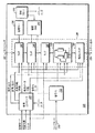
図1について説明すると、この図は、本明細書に記載する教示による走査コントローラを使用するプロセッサである。参照番号100はプロセッサ全体を示す。プロセッサ100は、一連のラッチ182〜188および走査チェーン180上に位置する状態機械150、機密保護キー130および機密保護ランダム・アクセス・メモリ(RAM)140のような感知可能情報の種々のソース、および走査チェーン180へのアクセスを制御し、リセットおよび/またはモード構成信号を供給する走査コントローラ120を含む。プロセッサ100は、またユーザのデータを暗号化するための暗号化ブロック110、および機密保護RAM140から情報をクリアするためのRAMリセット170を含む。走査チェーン180上にはいくつかの要素しか示していないが、例えば、暗号化ブロック110のような走査試験を必要とする任意の要素も走査チェーン180上に設置することができることに留意されたい。
Referring to FIG. 1, this figure is a processor that uses a scan controller in accordance with the teachings described herein.
アクセスから保護しなければならない情報は、配線識別キー(hardwired identification key)および専用ハードウェア/ファームウェアが実施したアルゴリズム、または製造後に記憶した感知可能情報のような、製造中にプロセッサ100内に記憶した情報を含むことができる。例えば、機密保護キー130は、特定の移動体通信デバイスを識別するために使用するハードウェア識別キーであってもよいし、状態機械150は、プロセッサのモードが機密保護動作モードであるかどうかを判断するた
めに、プロセッサ100が使用する一連の論理要素であってもよい。これらそれぞれの場合において、プロセッサ100内に組み込まれた情報は、偽造を防止するために、または競合者によるリバース・エンジニアリングをさらに困難にするために、機密保護状態に維持しなければならない。
Information that must be protected from access is stored in the
機密保護キー130は製造中に実施することができるが、機密保護RAM140は、製造プロセスが終了した後でプロセッサ100内で機密保護情報を記憶するための1つの方法である。例えば、プロセッサ100が無線インターネット装置で使用するグラフィックス・プロセッサであると仮定しよう。特定のサービス・プロバイダが専用のグラフィックス圧縮アルゴリズムを有している場合には、プロバイダは、暗号化したアルゴリズムをユーザ・データ入力109を通して、プロセッサ100内にロードすることができる。プロセッサ100は、次に、暗号化ブロック110によりこのアルゴリズムを解読し、解読したデータを記憶するために機密保護RAM140に転送する。当業者であれば、図1に示す方法の他に、または代わりに、プロセッサ100に情報を記憶するための適当な方法を本明細書の教示から逸脱することなしに使用することができることを理解することができるだろう。
While the
ラッチ182、184、186および188は、通常モードおよび試験モードの両方のモードで機能することができる。通常モードの場合には、ラッチ182および184および状態機械150は、プロセッサ100の他の部分が使用できるように感知可能情報を保持する。例えば、ラッチ182は、機密保護キー130にアクセスするために使用する多数のラッチのうちの1つであってもよく、機密保護キー130をプロセッサ100の認証部分(図示せず)に配信することができる。もう1つの例について説明すると、暗号化したソフトウェア・サブルーチンを、ラッチ184を通して機密保護RAM140から中央処理装置に送ることができる。ラッチ182または184が、正式な許可なしでアクセスしてはならない情報を含んでいる場合には、ラッチは読出感知可能情報を含んでいると言われる。
状態機械150は、プロセッサ100を非機密保護モードにするデータを保持することができる。状態機械150内の状態データを、走査モードから抜け出す直前に変更することができる場合には、プロセッサにモードが非機密保護モードであると思い込ませ、それにより機密保護動作が危険にさらされる恐れがある。走査モード動作の後で記憶から保護する必要があるデータを書込感知可能データと呼ぶことができる。他のラッチ(図示せず)は、読出または書込感知可能情報を含むことができる他の状態機械(図示せず)の出力を記憶するために使用することができる。これらの各例の場合、走査チェーンへのアクセスが保護されていない場合には、データのセキュリティが危険にさらされる恐れがある。
The
試験モードの場合には、ラッチ182、184、186および状態機械150に関連するラッチは、走査チェーン180を介して、プロセッサ100の外部から観察することができる。走査チェーン180へのアクセスは、スキャンイン・ポート181およびスキャンアウト・ポート189を通して行われる。データは、スキャンイン・ポート181を介して、ラッチ182、すなわち走査チェーン180上の第1の走査観察可能なラッチにクロック制御の下で送られる。データが、ラッチ182内にクロック制御の下で送られる度に、ラッチ182のところの出力データは、ラッチ184の入力に送られる。ラッチ182の出力データがラッチ184の入力に送られる度に、出力データ・ラッチ184がラッチ186の入力に送られ、データがチェーンを通してスキャンアウト・ポート189に送られるまで、同じ動作が反復して行われる。例えば、図の走査チェーン180において、論理1が第1のクロック・サイクル中にラッチ182内にクロック制御の下で送られたと仮定しよう。第2のクロック・サイクル中、ラッチ182内に記憶された論理1は、ラッチ184に配信される。第3のクロック・サイクル中、同じ論理1がラッチ186に送ら
れる。このプロセスは、最後に、論理1が読出しラッチ188に転送され、第4のクロック・サイクル中に、スキャンアウト・ポート189上での読出しのために使用できるようになるまで継続して行われる。当業者であれば、この簡単な例は単に例示としてのものに過ぎないこと、特定のラッチにシフトしたデータを走査チェーン180の残りの部分を通して送る前に、種々の方法で操作することができることを理解することができるだろう。
In the test mode, the
図の実施形態の場合には、読出しラッチ188は、ラッチ182、184および状態機械150とは対照的に、通常モード中、感知可能データを保持しない。代わりに、読出しラッチ188は、走査コントローラ120の制御の下で、ある所定の条件の場合を除いて、走査チェーンからのデータの読出しを阻止する。図示していないが、読出しラッチ188に類似の方法で制御されているラッチを、任意のデータが走査されるのを阻止するために、走査チェーン180への入力のところで使用できることを理解することができるだろう。また、以下に説明する種々の実施形態のような他の実施形態の場合には、読出しラッチ188を使用しないことも理解することができるだろう。
In the illustrated embodiment, read
走査コントローラ120は、走査チェーン180へのアクセスを制御し、それによりラッチ182、184および状態機械150に記憶することができるすべての感知可能情報へのアクセスを制御する。少なくとも1つの実施形態の場合には、走査コントローラ120は、入力としてTEST MODE信号、SCAN ENABLE信号、RESET信号、およびEVENT TRIGGER信号を受信する。これらの入力信号を使用して、走査コントローラ120は、SCAN ENABLE(INTERNAL)信号およびSCAN DATA ENABLE信号を生成し、これらの信号は走査試験を行うことができるように、ラッチ182〜188および状態機械150を構成するために使用される。例えば、アサートしたSCAN ENABLE(INTERNAL)は、各走査ラッチを走査モードにするが、アサートした走査データ・イネーブルは、データをスキャンアウト・ポート189に走査できるようにする。走査コントローラ120は、また必要に応じて走査チェーン180上の素子をリセットするために使用されるSCAN EXITおよびSCAN RESET信号を生成する。
図の実施形態の場合には、走査コントローラ120は、走査チェーン180に関連する大部分のリセット・シーケンスを制御し、各ラッチ182〜188および状態機械150が、確実に必要に応じて正しくリセットされるようにする。図の実施形態の場合には、感知可能情報を記憶するのに使用しないラッチ186および188は、感知可能情報を保護するためにリセットする必要がないことに留意されたい。しかし、「ハード」リセット中または他の時点でラッチ186および188をリセットすることが望ましい場合もあるので、走査コントローラ120へのRESET入力が、ラッチ186、188をリセットするために供給される。他の実施形態の場合には、RESET信号をSCAN RESET信号の他に、例えば、状態機械150のような機密保護走査チェーン素子に供給することができる。多くの状況の下で、走査チェーン上の各素子をリセットするのが望ましい場合があるが、非感知性要素は、本明細書の教示から逸脱することなしに、走査コントローラ120の出力によりリセットしない状態に保持することができる。
In the illustrated embodiment, the
一実施形態の場合には、RAMリセット170は、あるイベントに応じて機密保護RAM140から情報をクリアするために使用される。RAMリセット170は、別のリセット状態機械(図示せず)により、走査コントローラ120により直接、または他の方法により制御することができる。RAMリセット170は、また、機密保護RAM140内に記憶しているデータのクリアに成功したことを示すEVENT TRIGGER信号を供給することができる。この出力信号は、走査コントローラ120に対するEVENT TRIGGER入力として使用することができる。機密保護RAM140をリセットするのに必要な時間がはっきりしない場合には、EVENT TRIGGER信号を使用すると
特に有利である。図の実施形態ではRAMリセット170が使用されているが、すべての実施形態にとって必要なものではないことを理解することができるだろう。少なくとも一実施形態の場合には、SCAN DATA ENABLE信号、SCAN ENABLE(INTERNAL)信号、およびEVENT TRIGGER信号または他の類似の信号の生成が、少なくとも部分的には、走査チェーン180の素子内に含まれているデータが、リセットまたは他の方法により機密保護されているかどうかを示す信号(図1に図示せず)により制御される。このような信号の一実施形態としてはUNSECURE*信号があるが、これについては後で図5のところで説明する。
In one embodiment, RAM reset 170 is used to clear information from
図2を参照しながら、本発明のある実施形態によるプロセッサ100(図1)のようなプロセッサを走査試験するための方法について説明する。この方法はステップ210からスタートする。この場合、プロセッサ100は、通常モード、すなわち非試験モードで動作している。通常モードの場合には、走査チェーン180上の素子は、通常の処理タスクを実行するために使用される。走査チェーン180の素子が通常モードである場合には、これらの素子には、スキャンイン・ポート181またはスキャンアウト・ポート189を介してアクセスすることができない。何故なら、ラッチ182〜188および状態機械150は、その走査チェーン・ポートを介して情報を送受信するように構成されていないからである。通常モードの場合、ラッチ182、184および状態機械150は、感知可能データまたは状態情報を含むことができる。そのため、走査チェーン180上の素子が、通常動作中に走査チェーン・アクセスのために動作できるようにすることができる場合には、走査チェーンの素子内に含まれている任意の情報をスキャンアウト・ポート189から読み出すことができ、情報のセキュリティが危険にさらされる恐れがある。
With reference to FIG. 2, a method for scan testing a processor, such as processor 100 (FIG. 1), in accordance with an embodiment of the present invention will be described. The method starts at
この方法はステップ220に進む。このステップにおいては、リセットによる試験のために、または所望の入力または入力の組合せに応じて、走査チェーン・ラッチ182、184および状態機械150内の感知可能データを他の方法で修正するために走査チェーンの準備が行われる。例えば、一実施形態の場合には、アサートされたTEST MODE信号およびアサートされたSCAN ENABLE信号を受信すると、走査コントローラ120は、ラッチ182、184および状態機械150のリセット・ピンに直接供給することができるアサートされたSCAN RESET信号を生成する。別の方法としては、適当なハードウェア、ソフトウェアまたはファームウェア・コントローラは、機密保護データがラッチから決して検索されないように、ランダムにまたは他の方法でラッチ182、184および状態機械150内のデータを修正することができる。
The method proceeds to step 220. In this step, a scan is performed for testing by reset or to otherwise modify the sensitive data in scan chain latches 182, 184 and
ステップ230において、走査コントローラは、任意の感知可能データがクリアされたか、または他の方法で修正されたかをチェックする。ステップ230において、走査コントローラ120の入力のところにアサートされたEVENT TRIGGER信号が存在しているかどうかをチェックすることができ、EVENT TRIGGER信号がアサートされない場合には、SCAN ENABLE(INTERNAL)信号もアサートされない。例えば、走査チェーン180にアクセスできるようになる前に、機密保護RAM140をリセットしたい場合には、走査コントローラ120は、機密保護RAM140のリセットがすでに完了したことを示すRAMリセット170からの信号を受信するために待機することができる。他の実施形態の場合には、EVENT TRIGGER信号は必要ない。何故なら、走査チェーン素子内のデータの修正のためのタイミングが決定性であり、ステップ230が、ラッチ182〜184をリセットすることをできるようにするには十分な、多数のクロック・サイクルを単に待機するだけで行われるからである。
In
ステップ230において感知可能データが修正されると、走査コントローラ120は、ステップ240において走査チェーン180へのアクセスを許可する。ステップ240中に、当業者にとって周知の通常の走査試験手順を、走査チェーン180の走査観察可能素
子の中の任意の素子内にすでに記憶されていた感知可能情報のセキュリティを犠牲にしないで使用することができる。データをスキャンイン・ポート181内まで走査することができ、プロセッサ100の種々の内部の部分の機能を試験するために、スキャンアウト・ポート189から読出すことができる。
When the senseable data is modified at
走査試験が終了すると、図2の方法はステップ240からステップ250に進む。ステップ250において、走査試験モードから抜け出し、通常モードに再度入るための準備が行われる。一実施形態の場合には、ステップ250中は、走査チェーン180へのアクセスが阻止され、ラッチ182、184および状態機械150内の任意のデータが修正またはリセットされる。走査チェーン180は、TEST MODE信号のアサートを解除することにより、通常モードに入ることを走査コントローラ120(図1)に通知することにより阻止することができる。TEST MODE信号のアサートを解除するとそれに応じて、ラッチ182、184および状態機械150(図1)、および感知可能情報の読出しまたは書込みを含むことができる走査チェーン180の任意の他の素子をリセットするためにSCAN RESET信号をアサートすることができる。さらに、走査チェーンの観察可能部分上の素子を、データが走査により読み出されるのを防止するために再構成することができる。通常動作の目的で走査チェーンを準備するために使用した信号については、図7のところでさらに詳細に説明する。
When the scan test is complete, the method of FIG. 2 proceeds from
非試験状態に抜け出る前にプロセッサ100の走査観察可能な部分から情報をクリアすることにより、何者かが走査試験中に「シード」情報を走査するのを防止し、次に、シード情報に対してどんな動作が行われたのかを判断するために、プロセッサ100の出力を監視するのが防止される。また、この時点で情報をクリアすれば、何者かが、事実はそうでなくても、例えば、プロセッサに機密保護モードで動作していると「信じ込ませる」ことができる特定の状態に、例えば、状態機械150のような状態機械を設定するのが防止される。少なくとも1つの実施形態の場合には、ステップ250中に生成したSCAN EXIT信号を、すでに説明したように、データの修正/リセットの代わりにまたはこれに加えて、現在の状態が正確でないのかもしれないことを示すために、種々の状態機械への入力として使用することができる。状態機械は、次に、状態ビットが走査出口でクリアされてなくても、それ自身の上の既知の状態に遷移することができる。
Clearing the information from the scan observable portion of the
ステップ260において、走査コントローラ120は、ステップ230のところで説明したのと同じかまたは類似の技術により、プロセッサ100の任意の必要な走査観察可能な部分からデータがクリアされていることを確認するためにチェックを行う。例えば、一実施形態の場合には、走査コントローラ120は、データが走査チェーン180内にまたはからシフトするのを許可し、または防止するために使用することができるSCAN DATA ENABLE信号がアサートされる前に、リセットが終了したことを示すために、EVENT TRIGGER信号のアサートを待機することができる。図5のところでさらに詳細に説明する他の実施形態の場合には、UNSECURE*信号のアサートの解除を、EVENT TRIGGER信号がアサートされた場合に記述することができる。
In
図5のところで説明するUNSECURE*信号は、通常動作のための走査チェーン180上の種々の素子の構成を禁止または許可するために、走査チェーン180上の1つまたはそれ以上の素子を制御するために使用される。例えば、UNSECURE*は、データが出力されるのを防止するために、図1のSCAN DATA ENABLE信号のような制御信号の代わりに使用することができる。別の方法としては、UNSECURE*を、例えば、SCAN DATA ENABLEまたはSCAN ENABLE(INTERNAL)のような1つまたはそれ以上の信号を生成するために使用する論理回路への1つの入力として使用することができる。少なくとも1つの実施形態の場合には、UNSECURE*信号(図5)は、SCAN RESETおよびSCAN EXIT信号(図
3〜図4)両方の機能を結合する。データおよび/または状態情報がクリアされると、走査コントローラ120または他の適当なハードウェア、ソフトウェアまたはファームウェア素子は、プロセッサ100を通常モードに戻すことができる。
The UNSECURE * signal described in FIG. 5 is used to control one or more elements on the
図2の方法の種々のステップは、本発明の教示から逸脱することなしに、同時にまたは異なる順序で実施することができることを理解することができるだろう。例えば、ステップ230の場合のように、感知可能データが、走査観察可能素子からクリアされたかどうかを確認するためのチェックは、ステップ230の後でも実行することができるし、通常モード210でも実行することができる。別の方法としては、感知可能データがクリアされたかどうかのチェックは、継続的に行うこともできる。また、種々の設計、マーケティング、コスト、セキュリティまたは他の要因により、図2の方法のある部分を、他の部分を除いて実施することもできる。例えば、ステップ220の場合のように、試験モードに入る時に、いくつかのラッチ内のデータだけをクリアすることもできるし、ステップ250および260を、通常モードへ抜け出す前に、機密保護状態機械から状態情報をクリアするためだけに使用することができる。
It will be appreciated that the various steps of the method of FIG. 2 may be performed simultaneously or in a different order without departing from the teachings of the present invention. For example, as in
図3を参照しながら、走査コントローラ120の一部の特定の実施形態について説明する。この図の実施形態の場合には、走査コントローラ120の一部は、3つの入力、すなわち、TEST MODE、RESETおよびSCAN ENABLEを有する。これら3つの入力は、3つの出力、すなわち、SCAN ENABLE(INTERNAL)、SCAN RESETおよびSCAN EXITを生成するために組合わせて使用される。TEST MODEは、もっと簡単に試験できるように回路を機能的に修正するために使用する信号である。この信号は走査試験がスタートする前にアサートされる。SCAN
ENABLEは、データを走査チェーン内にシフトするために使用する信号であり、RESETは、内部データをクリアし、既知の状態に設定し、および/または他の方法で修正すべきであることを示す信号である。SCAN ENABLE(INTERNAL)は、走査チェーンを通してデータをシフトするために、SCAN ENABLEの代わりに、内部回路が使用するSCAN ENABLEをゲート制御したものである。SCAN RESETは、アサートされた場合、走査チェーンの走査観察可能素子から感知可能データをクリアするために使用することができる。SCAN EXITは、アサートされた場合、TEST MODE信号が示すように、試験モードのアサートがすでに解除されていて、既知の状態に強制的に状態遷移するために、状態機械への入力として使用することができることを示す信号である。
With reference to FIG. 3, some specific embodiments of the
ENABLE is a signal used to shift data into the scan chain, and RESET indicates that the internal data should be cleared, set to a known state, and / or otherwise modified Signal. SCAN ENABLE (INTERNAL) is a gate control of SCAN ENABLE used by the internal circuit instead of SCAN ENABLE to shift data through the scan chain. SCAN RESET, when asserted, can be used to clear sensitive data from the scan observable elements of the scan chain. SCAN EXIT, when asserted, should be used as an input to the state machine to force state transition to a known state, as the TEST MODE signal indicates that the test mode has already been deasserted It is a signal indicating that
走査コントローラ120の一部は、感知可能回路内の情報がクリアされるまで、データを決して走査チェーン内にシフトすることができないようにする。例えば、制御中の回路が試験モードであることを示すTEST MODE信号がアサートされるまで、データは走査チェーン内にシフトすることはできない。さらに、走査コントローラ120の一部は、TEST MODE信号がアサートされてから2つのクロック・サイクルまで、情報が走査チェーン内にシフトするのを遅延する。これにより、確実に、走査コントローラ120は、TEST MODE信号がアサートされた場合に自動的に生成されるSCAN RESETパルスを生成するための時間を有する。試験モードから抜け出した場合には、TEST MODE信号のアサートの解除が示すように、SCAN EXIT信号がアサートされる。信号のタイミングについては、図6および図7のところでさらに詳細に説明する。
A portion of
図4について説明すると、この図は走査コントローラ120の一部のもう1つの実施形態である。図の実施形態のロジックは、SCAN ENABLE(INTERNAL)のアサートが、この場合、EVENT TRIGGER信号のアサートの際に記述される点を除けば、図3のところで説明したロジックと本質的に同じものである。図3の走査コン
トローラは、必要な場合には、図4の走査コントローラが供給する機能を含むように修正することができることを理解することができるだろう。EVENT TRIGGER信号は、図1のところで説明したように、制御下の回路内の情報が必ず修正、リセット、クリア等されているようにするために、また走査チェーンのすべての素子または特定の素子がクリアされ、設定され、または他の方法で試験モードに入る準備ができているようにするための追加制御として使用される。EVENT TRIGGER信号を受信した場合だけ、出力信号、SCAN ENABLE(INTERNAL)が生成される。SCAN ENABLE(INTERNAL)信号は、データが走査チェーン内にまたはからシフトするのを防止する目的で、入力または出力ゲート、フリップフロップ等の制御を含んでいて、図3のところで説明したように使用することができる。
With reference to FIG. 4, this figure is another embodiment of a portion of the
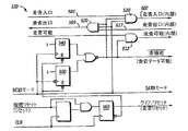
図5を参照しながら、非同期フリップフロップを使用する走査コントローラ120の一部からなるある実施形態について考察する。図5の実施形態は、図3および図4の実施形態と本質的に同じ効果を達成するために動作するが、若干異なるロジック構成を使用する。さらに、図5は、修正した走査コントローラまたは図1の他の回路の一部とすることができるゲート510および520を含むロジックも示す。
With reference to FIG. 5, consider an embodiment consisting of a portion of a
図5について説明すると、TEST MODE信号は、TEST MODE信号の立上がり縁部が、フリップフロップ540の出力を高レベルにし、TEST MODE信号の立下がり縁部がフリップフロップ550の出力を高レベルにするように、フリップフロップ540のクロック入力およびフリップフロップ550の倒置クロック入力に送られる。
Referring to FIG. 5, the TEST MODE signal is such that the rising edge of the TEST MODE signal causes the output of the flip-
それ故、TEST MODEの任意の遷移は、フロップへのRESET入力のアサートが解除されると仮定した場合、UNSECURE*をアサートさせる。UNSECURE*がアサートされると、SCAN ENABLE INTERNALのアサートが解除され、走査チェーンの動作を防止する。非同期状態にあるフリップフロップ540および550のリセット入力は、フリップフロップ560の倒置出力に接続され、そのためフリップフロップ540および550は、SECURE RESET信号に応じてリセットされる。SECURE RESETは、ユーザの動作に応じて、または他の方法で、システム・リセットの一部として生成することができる。少なくとも1つの実施形態の場合には、SECURE RESETは、図1のRESET信号の特別な例である。フリップフロップ540および550の信号入力は、高い基準電圧に接続しているので、SECURE RESET信号が少なくとも2つのクロック・サイクルの間アサートされると、アクティブ・ローの論理信号、UNSECURE*のアサートが解除され(すなわち、論理ハイ値になり)、感知可能データが機密保護されていることを示す。
Therefore, any transition in TEST MODE causes UNSECURE * to be asserted, assuming that the RESET input to the flop is deasserted. When UNSECURE * is asserted, SCAN ENABLE INTERNAL is deasserted, preventing the scan chain from operating. The reset inputs of flip-
図の実施形態の場合には、SECURE RESET信号がアサートされる前に、TEST MODEがアサートされると、アサートされたSECURE RESET信号を受信した後で、UNSECURE*信号のアサートが解除され、感知可能データが機密保護されていることを示し、SECURE RESET信号のアサートが解除された後でも、UNSECURE*はアサートされないままになる。しかし、TEST MODE信号が、SECURE RESET信号のアサートが解除された後で状態を変えると、UNSECURE*信号がアサートされ、走査チェーン内のデータは機密保護されないことを示す。UNSECURE*信号の機能の理解を容易にするために、以下の節においてその例について考察する。 In the illustrated embodiment, if TEST MODE is asserted before the SECURE RESET signal is asserted, the UNSECURE * signal is deasserted after the asserted SECURE RESET signal is received and can be sensed. UNSECURE * remains unasserted even after the SECURE RESET signal is deasserted, indicating that the data is secure. However, if the TEST MODE signal changes state after the SECURE RESET signal is deasserted, the UNSECURE * signal is asserted, indicating that the data in the scan chain is not secured. To facilitate an understanding of the function of the UNSECURE * signal, an example is considered in the following section.
下記の例について考察する場合、SCAN IN(INTERNAL)507、SCAN OUT(INTERNAL)517、およびSCAN ENABLE(INTERNAL)は、SCAN IN181、SCAN OUT189およびSCAN ENABLE(図1)をゲート制御したものであり、これらすべては走査チェーン180の外部アク
セスを制限するために使用することができることに留意されたい。SCAN IN(INTERNAL)およびSCAN OUT(INTERNAL)は、図1にははっきりと示してないが、実施した場合、図1のSCAN INおよびSCAN OUT信号をゲート制御することに留意されたい。例えば、走査チェーン180(図1)のモードが、現在走査試験モードになっていて、TEST MODE信号はアサートされ、UNSECURE*信号はアサート解除されていると仮定しよう。走査試験モードから抜け出すために、TEST MODE信号のアサートが解除される。フリップフロップ550は、TEST MODE信号の立下がり縁部によりトリガされ、それによりUNSECURE*がアサートされる。アサートされたUNSECURE*信号は、走査試験モードから抜け出していることを示し、また走査チェーン180(図1)内のデータをクリアする必要があることを示す。図の実施形態の場合には、UNSECURE*は、データSCAN IN581が、ANDゲート510を通過し、走査チェーン180(図1)内に走査することができるSCAN IN(INTERNAL)データ507になるのを阻止するための、またデータSCAN OUT(INTERNAL)517が走査チェーン180(図1)から読み出されるのを阻止するための論理ゲート510への入力として使用される。さらに、UNSECURE*は、SCAN ENABLE(INTERNAL)が、データが機密保護されていない場合、SCAN ENABLEに応じてアサートされるのを阻止するための論理ゲート512への入力として使用される。これらの方法の中の任意のものを、データがデバイス100から走査されるのを防止するために使用することができることを理解することができるだろう。
When considering the example below, SCAN IN (INTERNAL) 507, SCAN OUT (INTERNAL) 517, and SCAN ENABLE (INTERNAL) are gated SCAN IN181, SCAN OUT189 and SCAN ENABLE (FIG. 1), Note that all of these can be used to limit external access of
論理ゲート510、512および520への入力として使用されるほかに、UNSECURE*信号は、例えば、SECURE RESET信号をアサートするために、または他の方法で走査チェーン内のデータをクリアする目的で、中央プロセッサに通知するために使用することができる。UNSECURE*信号は、また、種々のファームウェアまたはソフトウェアが走査チェーンの状態を判断するために参照することができる機密保護/非機密保護レジスタ(図示せず)を設定するためにも使用することができる。別の方法としては、UNSECURE*信号を、図1の1つまたはそれ以上のラッチまたは状態機械の構成を制御するための直接入力として使用することができる。
In addition to being used as an input to
最後に、図5の実施形態は、走査チェーンの走査観察可能素子内に記憶されているデータを修正する目的で、アサートされたCLEAR/RESET信号を生成するために、SECURE RESET信号を使用する。CLEAR/RESETは、図1のSCAN RESETに類似しているものでもよいことに留意されたい。SECURE RESET信号は、走査コントローラ120を使用するプロセッサ内の他の回路により自動的に生成することができるか、またはシステムを、オペレータがリセットを物理的にスタートした後でだけ、SECURE RESET信号を生成するように構成することができる。
Finally, the embodiment of FIG. 5 uses the SECURE RESET signal to generate an asserted CLEAR / RESET signal for the purpose of modifying the data stored in the scan observable elements of the scan chain. Note that CLEAR / RESET may be similar to SCAN RESET of FIG. The SECURE RESET signal can be automatically generated by other circuitry in the processor using the
図3および図6を参照しながら、走査コントローラの一実施形態で使用する信号間のタイミングの関係について説明する。図6は、試験モードに入った場合のタイミングの関係である。以下の説明のすべてのタイミングは、クロック610を基準にしていて、特にクロック・サイクルC1の第1の立上がり縁部を基準にしている。クロック・サイクルC1がスタートする前に、すべての信号のアサートが解除され、動作モードが通常モード、すなわち、非試験モードであることを示す。クロック・サイクルC1の前の半分の間に、ユーザはSCAN ENABLE630をアサートすることにより走査ができるようにしようとする。走査コントローラ120を使用しているプロセッサは、依然として通常モードで動作しているので、SCAN ENABLE630をアサートしても、SCAN ENABLE(INTERNAL)640は高レベルにならない。
The timing relationship between signals used in one embodiment of the scan controller will be described with reference to FIGS. FIG. 6 shows the timing relationship when the test mode is entered. All timings in the following description are relative to
しかし、第2のクロック・サイクルC2の第1の立上がり縁部のところで、TEST
MODE620がアサートされる。SCAN RESET660は、TEST MODE620がアサートされると高レベルになる。SCAN RESET660は、走査チェーン上の走査観察可能素子の修正、リセットまたはクリアをトリガするパルスである(図1参照)。クロック・サイクルC4の第1の立上がり縁部のところで、TEST MODE620の後の2つの立ち上がりクロック縁部がアサートされ、SCAN ENABLE630およびTEST MODE620の両方が高レベルになっているので、SCAN ENABLE(INTERNAL)640が高レベルになる。2つのクロック・サイクル中、SCAN ENABLE(INTERNAL)640のアサートを遅らせることにより、走査チェーンへのアクセスが許可される前にリセットを行うことができる。それにより、試験モードになった場合、感知可能情報を保護する。RESET650およびSCAN
EXIT670は、試験モード中にはアサートされないことに留意されたい。サイクルC4のところでSCAN ENABLE(INTERNAL)がアサートされてから後しばらく経過した後で、サイクルC1のところでアサートされているTEST MODE620に応じて、内部プロセッサの構成要素の試験を容易にするために、走査チェーン内におよびからデータをシフトすることができるが、この時点ですべての機密保護情報はクリアされる。
However, at the first rising edge of the second clock cycle C2, TEST
Note that
図3および図7を参照しながら、走査コントローラの一実施形態の信号間のタイミングの関係、特に試験モードから抜け出した場合のタイミングの関係についてさらに詳細に説明する。図7の信号のタイミングの関係について、クロック・サイクルC1の第1の立上がり縁部を参照しながら説明する。クロック・サイクルC1のスタートのところで、TEST MODE720、SCAN ENABLE730およびSCAN ENABLE(INTERNAL)740がアサートされ、一方、すべての他の信号が取り消される。このことは、感知可能データの漏洩を心配しないで、走査チェーン内におよびからデータを自由にシフトすることができる試験モードに対応する。クロック・サイクルC1の立下がり縁部のところで、TEST MODE720が取り消され、試験サイクルの終了および通常モードへの移行が通知される。TEST MODE720が取り消されるのと同時に、最後にRESET750がアサートされて以来試験モードに入っていて、そのモードから抜け出したことを通知するためにSCAN EXIT770がアサートされる。SCAN EXIT770は、既知の状態に強制的に状態遷移するための状態機械への入力として使用することができ、ラッチの動作状態を制御するためのラッチへの入力として使用することができ、走査チェーン内のデータを通常動作で使用することができる前にリセットする必要があることを表示するためにプロセッサに結合することができ、または走査試験モードから抜け出したことを表示するために種々の他の類似の方法で使用することができる。
With reference to FIGS. 3 and 7, the timing relationship between signals in one embodiment of the scan controller, in particular, the timing relationship when exiting the test mode will be described in more detail. The timing relationship of the signals in FIG. 7 will be described with reference to the first rising edge of clock cycle C1. At the start of clock cycle C1,
第2のクロック・サイクルC2の立下がり縁部のところで、RESET750がアサートされ、それによりSCAN RESET760がアサートされる。SCAN RESET760は、少なくとも1つの実施形態の場合には、走査チェーンを形成しているデータ・ラッチおよび状態機械へのリセット入力として使用される。このように使用された場合には、SCAN RESET760は、走査試験モードから抜け出した場合に、走査チェーンから感知可能データをクリアする。SCAN ENABLE(INTERNAL)740は、SCAN EXIT770が取り消されるのと同時に低レベルになり、それにより、走査試験モードから抜け出した後で、走査チェーンからデータが走査されるのを防止する。最後に、SCAN ENABLE730のアサートが解除され、そのため追加のデータを走査チェーン内に走査することができない。現在タイミングを考察している走査コントローラ120の実施形態の場合には、SCAN RESET760は、TEST MODE720が取り消された場合、自動的にはアサートされないことに留意されたい。その代わりに、RESET750を、ユーザの動作または他の方法に応じてアサートしなければならないし、それにより、通常モードに入る前に走査チェーンをクリアするためにS
CAN RESET760がアサートされる。他の実施形態は、試験モードから抜け出した場合に、RESET750に類似のリセット・パルスを自動的に生成することができる。
At the falling edge of the second clock cycle C2,
CAN RESET 760 is asserted. Other embodiments can automatically generate a reset pulse similar to
要するに、上記説明をよく読めば、走査チェーンへのアクセスの許可の前および後で、プロセッサの走査観察可能部分内に記憶している情報を修正することにより、本明細書の教示により組立てた走査コントローラを使用するプロセッサは、試験性能を犠牲にしないでデータのセキュリティを強化することができることは明らかである。データのセキュリティが強化されると、自称模倣者がデータにアクセスするのを制限することにより感知可能データを簡単に利用できないようにすることができる。同時に、試験性能の向上により、製造コストを安くし、市場への製品の導入をスピードアップすることができる。 In short, if the above description is read carefully, scans constructed according to the teachings herein by modifying the information stored in the scan observable portion of the processor before and after granting access to the scan chain. Obviously, a processor using a controller can enhance data security without sacrificing test performance. As data security is enhanced, sensitive data can be made simply unavailable by restricting access to the data by self-imitators. At the same time, improved test performance can reduce manufacturing costs and speed up the introduction of products to the market.
図面の上記詳細な説明において、本明細書の一部を構成していて、本発明を実行することができる例示としての特定の実施形態を示す添付の図面を参照した。これらの実施形態については、当業者が本発明を実行できるようにするために十分詳細に説明してあるが、他の実施形態も使用できること、また本発明の精神および範囲から逸脱することなしに、論理的、機械的、化学的、および電気的変更を行うことができることを理解されたい。 In the foregoing detailed description of the drawings, reference has been made to the accompanying drawings that form a part hereof, and in which are shown by way of illustration specific embodiments in which the invention may be practiced. These embodiments have been described in sufficient detail to enable those skilled in the art to practice the invention, but other embodiments can be used and without departing from the spirit and scope of the invention. It should be understood that logical, mechanical, chemical, and electrical changes can be made.
当業者が本発明を実行できるようにするために必要ではない詳細な説明を避けるために、当業者であれば周知のいくつかの情報を省略することができる。さらに、当業者であれば、本発明の教示を含む多くの他の変形した実施形態を容易に組立てることができるだろう。それ故、本発明の説明は、本明細書に記載した特定の形状に限定されるものではなく、それどころかこのような代替物、変形したものおよび等価物を、当然本発明の精神および範囲内に含まれるものとしてカバーする。それ故、上記の詳細な説明は、本発明を制限するものではなく、本発明の開示の範囲は添付の特許請求の範囲によってだけ定義される。 To avoid detailed descriptions not necessary to enable those skilled in the art to practice the invention, some information known to those skilled in the art may be omitted. Moreover, those skilled in the art will readily be able to assemble many other modified embodiments that include the teachings of the present invention. Therefore, the description of the present invention is not limited to the specific shapes described herein, but rather, such alternatives, modifications and equivalents are naturally within the spirit and scope of the present invention. Cover as included. Therefore, the above detailed description does not limit the invention. The scope of the disclosure is defined only by the appended claims.
Claims (10)
前記構成信号に応じて、データ・プロセッサの走査観察可能部分の情報を修正するステップと、
前記修正ステップの後で、前記走査観察可能部分の走査試験をできるようにするステップと、を含む方法。 Receiving a configuration signal and preparing a scan chain (180) for testing;
Modifying the information of the scan observable portion of the data processor in response to the configuration signal;
Enabling a scan test of the scan-observable portion after the modifying step.
前記走査試験をできるようにするステップが、イネーブル走査信号を生成して前記走査観察可能部分内で走査ロジックを動作できるようにすること、を含む請求項1に記載の方法。 The modifying step comprises resetting the scan observable portion in response to the configuration signal;
The method of claim 1, wherein enabling the scan test comprises generating an enable scan signal to enable scanning logic within the scan observable portion.
前記走査試験をできるようにするステップの前に、前記走査観察可能部分から情報が走査されるのを防止するステップと、をさらに含む請求項1に記載の方法。 Preventing the scan-observable portion from being scanned before the step of enabling the scanning test;
The method of claim 1, further comprising preventing information from being scanned from the scan observable portion prior to enabling the scan test.
前記構成インジケータに応じて、データ・プロセッサ(100)の走査観察可能部分の情報を修正するステップと、
前記修正ステップの後で前記データ・プロセッサの通常動作を可能にするステップとを含む方法。 Receiving the configuration indicator and preparing the scan chain (180) for normal operation;
Modifying the scan observable portion information of the data processor (100) in response to the configuration indicator;
Enabling the normal operation of the data processor after the modifying step.
前記走査試験をできるようにするステップの後で、前記走査観察可能な部分から情報が走査されるのを防止するステップとをさらに含む、請求項4に記載の方法。 Preventing information from being scanned into the scan observable portion after enabling the scanning test;
5. The method of claim 4, further comprising the step of preventing information from being scanned from the scan-observable portion after the step of enabling the scan test.
前記機能部分を試験する前に、前記機能部分の情報を修正することにより、前記機密保護情報へのアクセスを防止するための試験制御部分とを備えるプロセッサ。 A functional part for processing security information during normal mode, which can be observed during test mode;
A processor comprising: a test control portion for preventing access to the security information by modifying information of the functional portion before testing the functional portion.
Applications Claiming Priority (2)
| Application Number | Priority Date | Filing Date | Title |
|---|---|---|---|
| US10/135,877 US7185249B2 (en) | 2002-04-30 | 2002-04-30 | Method and apparatus for secure scan testing |
| PCT/US2003/011399 WO2004051294A1 (en) | 2002-04-30 | 2003-04-14 | Method and apparatus for secure scan testing |
Publications (2)
| Publication Number | Publication Date |
|---|---|
| JP2006505798A true JP2006505798A (en) | 2006-02-16 |
| JP2006505798A5 JP2006505798A5 (en) | 2006-06-01 |
Family
ID=29249555
Family Applications (1)
| Application Number | Title | Priority Date | Filing Date |
|---|---|---|---|
| JP2004557093A Pending JP2006505798A (en) | 2002-04-30 | 2003-04-14 | Method and apparatus for security scanning test |
Country Status (9)
| Country | Link |
|---|---|
| US (2) | US7185249B2 (en) |
| EP (1) | EP1499906B1 (en) |
| JP (1) | JP2006505798A (en) |
| KR (1) | KR100966661B1 (en) |
| CN (1) | CN100381834C (en) |
| AU (1) | AU2003224959A1 (en) |
| DE (1) | DE60303126T2 (en) |
| TW (1) | TWI270768B (en) |
| WO (1) | WO2004051294A1 (en) |
Cited By (3)
| Publication number | Priority date | Publication date | Assignee | Title |
|---|---|---|---|---|
| JP2011525015A (en) * | 2008-06-04 | 2011-09-08 | エーティーアイ・テクノロジーズ・ユーエルシー | Method and apparatus for protecting digital information in an integrated circuit during a test mode of operation |
| JP2011528144A (en) * | 2008-07-14 | 2011-11-10 | テレフオンアクチーボラゲット エル エム エリクソン(パブル) | Integrated circuit, method and electronic apparatus |
| JP2013002848A (en) * | 2011-06-13 | 2013-01-07 | Fujitsu Semiconductor Ltd | Semiconductor device |
Families Citing this family (75)
| Publication number | Priority date | Publication date | Assignee | Title |
|---|---|---|---|---|
| US7228440B1 (en) * | 2002-02-13 | 2007-06-05 | Lsi Corporation | Scan and boundary scan disable mechanism on secure device |
| US7672452B2 (en) * | 2002-05-03 | 2010-03-02 | General Instrument Corporation | Secure scan |
| JP2007506088A (en) * | 2003-09-19 | 2007-03-15 | コニンクリユケ フィリップス エレクトロニクス エヌ.ブイ. | Electronic circuit with secret submodule |
| TWI229741B (en) * | 2004-01-16 | 2005-03-21 | Sunplus Technology Co Ltd | Device and method for accessing hidden data in boundary scan test interface |
| TWI235599B (en) * | 2004-01-16 | 2005-07-01 | Sunplus Technology Co Ltd | Device and method for transmitting hidden signal in boundary scan testing interface |
| EP1560033A1 (en) * | 2004-01-29 | 2005-08-03 | STMicroelectronics S.A. | Integrated circuit comprising a secure test mode by resetting of said test mode |
| FR2865828A1 (en) * | 2004-01-29 | 2005-08-05 | St Microelectronics Sa | METHOD FOR SECURING THE TEST MODE OF AN INTEGRATED CIRCUIT BY INTRUSION DETECTION |
| FR2865827A1 (en) * | 2004-01-29 | 2005-08-05 | St Microelectronics Sa | SECURING THE TEST MODE OF AN INTEGRATED CIRCUIT |
| US7490231B2 (en) * | 2004-07-23 | 2009-02-10 | Broadcom Corporation | Method and system for blocking data in scan registers from being shifted out of a device |
| US7290191B2 (en) * | 2004-08-20 | 2007-10-30 | International Business Machines Corporation | Functional frequency testing of integrated circuits |
| WO2006053586A1 (en) * | 2004-11-22 | 2006-05-26 | Freescale Semiconductor, Inc. | Integrated circuit and a method for secure testing |
| FR2884000A1 (en) * | 2005-04-05 | 2006-10-06 | St Microelectronics Sa | Cryptographic coprocessor control execution monitoring method for integrated circuit, involves carrying error signal if abnormal flow of execution is detected and preventing access to register as long as signal is given with active value |
| US7519883B1 (en) * | 2005-04-05 | 2009-04-14 | Advanced Micro Devices, Inc. | Method of configuring a system and system therefor |
| FR2883998A1 (en) * | 2005-04-05 | 2006-10-06 | St Microelectronics Sa | Coprocessor`s control execution securing method for e.g. microcontroller, involves placing coprocessor in default error mode from commencement of execution of control accomplished by coprocessor |
| FR2885417A1 (en) * | 2005-05-04 | 2006-11-10 | St Microelectronics Sa | INTEGRATED CIRCUIT COMPRISING A SECURED TEST MODE BY DETECTING THE CHAIN STATE OF THE CONFIGURABLE CELLS OF THE INTEGRATED CIRCUIT |
| US7334173B2 (en) * | 2005-06-28 | 2008-02-19 | Transmeta Corporation | Method and system for protecting processors from unauthorized debug access |
| US7600166B1 (en) * | 2005-06-28 | 2009-10-06 | David Dunn | Method and system for providing trusted access to a JTAG scan interface in a microprocessor |
| US7694197B2 (en) * | 2005-07-08 | 2010-04-06 | Stmicroelectronics, Sa | Integrated circuit comprising a test mode secured by detection of the state of a control signal |
| FR2888330B1 (en) * | 2005-07-08 | 2007-10-05 | St Microelectronics Sa | INTEGRATED CIRCUIT COMPRISING A SECURED TEST MODE BY DETECTING THE STATUS OF A CONTROL SIGNAL |
| US7363564B2 (en) * | 2005-07-15 | 2008-04-22 | Seagate Technology Llc | Method and apparatus for securing communications ports in an electronic device |
| DE602006014417D1 (en) | 2005-08-10 | 2010-07-01 | Nxp Bv | INSPECT AN INTEGRATED CIRCUIT CONTAINING SECRET INFORMATION |
| US7328384B1 (en) * | 2005-09-29 | 2008-02-05 | Xilinx, Inc. | Method and apparatus using device defects as an identifier |
| JP2007171060A (en) * | 2005-12-23 | 2007-07-05 | Toshiba Corp | Operating mode setting circuit, lsi having the operating mode setting circuit, and operating mode setting method |
| FR2897440A1 (en) * | 2006-02-10 | 2007-08-17 | St Microelectronics Sa | ELECTRONIC CIRCUIT COMPRISING A TESTED CHAIN BREAKING TESTING MODE AND ASSOCIATED METHOD. |
| US7779252B2 (en) * | 2006-03-21 | 2010-08-17 | Harris Corporation | Computer architecture for a handheld electronic device with a shared human-machine interface |
| US8127145B2 (en) * | 2006-03-23 | 2012-02-28 | Harris Corporation | Computer architecture for an electronic device providing a secure file system |
| US8041947B2 (en) * | 2006-03-23 | 2011-10-18 | Harris Corporation | Computer architecture for an electronic device providing SLS access to MLS file system with trusted loading and protection of program execution memory |
| US8060744B2 (en) * | 2006-03-23 | 2011-11-15 | Harris Corporation | Computer architecture for an electronic device providing single-level secure access to multi-level secure file system |
| US7979714B2 (en) * | 2006-06-02 | 2011-07-12 | Harris Corporation | Authentication and access control device |
| JP4262265B2 (en) * | 2006-06-20 | 2009-05-13 | キヤノン株式会社 | Semiconductor integrated circuit |
| FR2903497A1 (en) * | 2006-07-07 | 2008-01-11 | St Microelectronics Sa | ELECTRONIC CIRCUIT COMPRISING A SECURE TEST MODE BY INSERTING LURE DATA IN THE TEST CHAIN, AND ASSOCIATED METHOD. |
| CN100495989C (en) * | 2006-07-07 | 2009-06-03 | 中国科学院计算技术研究所 | A test shell circuit and its design method |
| US8528102B2 (en) * | 2006-10-06 | 2013-09-03 | Broadcom Corporation | Method and system for protection of customer secrets in a secure reprogrammable system |
| US7869915B2 (en) * | 2007-04-12 | 2011-01-11 | GM Global Technology Operations LLC | Method and apparatus for validating processors using seed and key tests |
| US9111122B2 (en) * | 2007-07-02 | 2015-08-18 | Freescale Semiconductor, Inc. | Asymmetric cryptographic device with local private key generation and method therefor |
| US7975307B2 (en) * | 2007-09-07 | 2011-07-05 | Freescale Semiconductor, Inc. | Securing proprietary functions from scan access |
| US7987331B2 (en) * | 2007-11-15 | 2011-07-26 | Infineon Technologies Ag | Method and circuit for protection of sensitive data in scan mode |
| US8397079B2 (en) * | 2008-06-04 | 2013-03-12 | Ati Technologies Ulc | Method and apparatus for securing digital information on an integrated circuit read only memory during test operating modes |
| CN102112889A (en) * | 2008-08-08 | 2011-06-29 | Nxp股份有限公司 | Circuit with testable circuit coupled to privileged information supply circuit |
| US8074132B2 (en) * | 2008-10-28 | 2011-12-06 | Broadcom Corporation | Protecting data on integrated circuit |
| JP2010252305A (en) * | 2009-03-25 | 2010-11-04 | Renesas Electronics Corp | Semiconductor integrated circuit and control method of the same |
| JP2010261768A (en) * | 2009-05-01 | 2010-11-18 | Sony Corp | Semiconductor integrated circuit, information processing apparatus, output data diffusion method, and program |
| JP2010266417A (en) * | 2009-05-18 | 2010-11-25 | Sony Corp | Semiconductor integrated circuit, information processing apparatus and method, and program |
| US9009552B2 (en) * | 2010-09-09 | 2015-04-14 | Advanced Micro Devices, Inc. | Scan-based reset |
| CN102565684A (en) * | 2010-12-13 | 2012-07-11 | 上海华虹集成电路有限责任公司 | Security-based scan chain control circuit, scan chain testing circuit and use method |
| US9746519B2 (en) * | 2011-03-25 | 2017-08-29 | Nxp B.V. | Circuit for securing scan chain data |
| US8495443B1 (en) | 2011-05-31 | 2013-07-23 | Apple Inc. | Secure register scan bypass |
| US20140149729A1 (en) | 2011-07-18 | 2014-05-29 | Ted A. Hadley | Reset vectors for boot instructions |
| US9373377B2 (en) | 2011-11-15 | 2016-06-21 | Micron Technology, Inc. | Apparatuses, integrated circuits, and methods for testmode security systems |
| US9224012B2 (en) * | 2013-05-20 | 2015-12-29 | Advanced Micro Devices, Inc. | Debug functionality in a secure computing environment |
| US9310436B2 (en) * | 2014-01-28 | 2016-04-12 | Omnivision Technologies, Inc. | System and method for scan-testing of idle functional units in operating systems |
| CN106556792B (en) * | 2015-09-28 | 2021-03-19 | 恩智浦美国有限公司 | Integrated circuit capable of secure scanning |
| GB2543804A (en) * | 2015-10-29 | 2017-05-03 | Nordic Semiconductor Asa | Microprocessor interfaces |
| US10185633B2 (en) * | 2015-12-15 | 2019-01-22 | Intel Corporation | Processor state integrity protection using hash verification |
| EP3430627B1 (en) * | 2016-03-16 | 2022-01-12 | Hewlett-Packard Development Company, L.P. | Controlling a transition between a functional mode and a test mode |
| CN107783030B (en) * | 2016-08-29 | 2021-04-23 | 恩智浦美国有限公司 | Integrated circuit with low power scanning system |
| CN108073832B (en) * | 2016-11-15 | 2021-06-29 | 华为技术有限公司 | Data security protection method and equipment |
| US10222417B1 (en) * | 2016-11-28 | 2019-03-05 | Cadence Design Systems, Inc. | Securing access to integrated circuit scan mode and data |
| US10223531B2 (en) | 2016-12-30 | 2019-03-05 | Google Llc | Secure device state apparatus and method and lifecycle management |
| CN106707139B (en) * | 2017-01-03 | 2019-06-04 | 大唐微电子技术有限公司 | A kind of testing scanning chain device and implementation method |
| KR102220662B1 (en) * | 2018-01-05 | 2021-03-17 | 주식회사 아이씨티케이 홀딩스 | Apparatus and method for protecting data in test mode |
| US11222098B2 (en) * | 2018-08-23 | 2022-01-11 | University Of Florida Research Foundation, Incorporated | Protecting obfuscated circuits against attacks that utilize test infrastructures |
| US10984108B2 (en) | 2018-10-05 | 2021-04-20 | International Business Machines Corporation | Trusted computing attestation of system validation state |
| US10976366B2 (en) * | 2018-10-19 | 2021-04-13 | Silicon Laboratories Inc. | Two pin scan interface for low pin count devices |
| CN110020558A (en) * | 2019-04-09 | 2019-07-16 | 长沙理工大学 | A kind of safe crypto chip Testability Design structure under boundary scan design environment |
| TWI727308B (en) * | 2019-04-17 | 2021-05-11 | 國立成功大學 | Dynamic-key defense structure for testing circuit and method thereof |
| US11144677B2 (en) * | 2019-08-08 | 2021-10-12 | Nxp Usa, Inc. | Method and apparatus for digital only secure test mode entry |
| EP3999990A4 (en) * | 2019-09-12 | 2022-08-17 | Fingerprint Cards Anacatum IP AB | Biometric device with cryptographic circuitry |
| US10955473B1 (en) | 2019-11-01 | 2021-03-23 | Nxp B.V. | System and method of scan reset upon entering scan mode |
| US11320482B2 (en) | 2020-02-26 | 2022-05-03 | Silicon Laboratories Inc. | Secure scan entry |
| EP3893008A1 (en) * | 2020-04-07 | 2021-10-13 | Commsolid GmbH | Method and apparatus for performing a secure test mode of a soc |
| EP4334730A1 (en) * | 2021-05-04 | 2024-03-13 | Texas Instruments Incorporated | Methods and apparatus for using scan operations to protect secure assets |
| US20220358230A1 (en) * | 2021-05-04 | 2022-11-10 | Texas Instruments Incorporated | Methods and apparatus for using scan operations to protect secure assets |
| US11454671B1 (en) * | 2021-06-30 | 2022-09-27 | Apple Inc. | Data gating using scan enable pin |
| US11953548B2 (en) * | 2022-01-14 | 2024-04-09 | University Of Florida Research Foundation, Incorporated | Invisible scan architecture for secure testing of digital designs |
Citations (9)
| Publication number | Priority date | Publication date | Assignee | Title |
|---|---|---|---|---|
| JPS63118951A (en) * | 1986-11-07 | 1988-05-23 | Oki Electric Ind Co Ltd | Single chip microcomputer |
| JPH01118933A (en) * | 1987-10-31 | 1989-05-11 | Nec Corp | Single-chip microcomputer |
| JPH0325688A (en) * | 1989-06-23 | 1991-02-04 | Nec Corp | Microcomputer |
| JPH04256145A (en) * | 1991-02-08 | 1992-09-10 | Sharp Corp | Integrated circuit device |
| JPH0512459A (en) * | 1991-07-05 | 1993-01-22 | Nec Corp | Single-chip microcomputer |
| JPH10503038A (en) * | 1994-07-14 | 1998-03-17 | ナショナル ウェストミンスター バンク ピーエルシー | Testing memory contents |
| JPH1126463A (en) * | 1997-07-09 | 1999-01-29 | Toshiba Corp | Semiconductor device |
| JPH11175403A (en) * | 1997-12-05 | 1999-07-02 | Tokyo Electron Ltd | Test method for storage device and memory provided with test function |
| JPH11282671A (en) * | 1998-03-31 | 1999-10-15 | Texas Instr Japan Ltd | Computer system |
Family Cites Families (24)
| Publication number | Priority date | Publication date | Assignee | Title |
|---|---|---|---|---|
| US4925353A (en) | 1987-05-28 | 1990-05-15 | Litton Systems, Inc. | Drive fastening system |
| US4947357A (en) * | 1988-02-24 | 1990-08-07 | Stellar Computer, Inc. | Scan testing a digital system using scan chains in integrated circuits |
| JPH01307815A (en) * | 1988-06-07 | 1989-12-12 | Mitsubishi Electric Corp | Reset system for information processor |
| JPH06214821A (en) * | 1992-03-02 | 1994-08-05 | Motorola Inc | Data processing system provided with sequential self-address decoding function and its operating method |
| US5627842A (en) * | 1993-01-21 | 1997-05-06 | Digital Equipment Corporation | Architecture for system-wide standardized intra-module and inter-module fault testing |
| GB2290877B (en) * | 1994-07-01 | 1997-08-20 | Advanced Risc Mach Ltd | Integrated circuit test controller |
| US5530753A (en) | 1994-08-15 | 1996-06-25 | International Business Machines Corporation | Methods and apparatus for secure hardware configuration |
| KR0147619B1 (en) * | 1995-01-27 | 1998-12-01 | 김광호 | Flip-flop controller |
| US5898776A (en) | 1996-11-21 | 1999-04-27 | Quicklogic Corporation | Security antifuse that prevents readout of some but not other information from a programmed field programmable gate array |
| US6049901A (en) | 1997-09-16 | 2000-04-11 | Stock; Mary C. | Test system for integrated circuits using a single memory for both the parallel and scan modes of testing |
| US6061010A (en) | 1997-09-25 | 2000-05-09 | Analog Devices, Inc. | Dual return-to-zero pulse encoding in a DAC output stage |
| US6425100B1 (en) * | 1998-04-24 | 2002-07-23 | Texas Instruments Incorporated | Snoopy test access port architecture for electronic circuits including embedded core with built-in test access port |
| US6304099B1 (en) * | 1998-05-21 | 2001-10-16 | Lattice Semiconductor Corporation | Method and structure for dynamic in-system programming |
| US6216251B1 (en) * | 1999-04-30 | 2001-04-10 | Motorola Inc | On-chip error detection and correction system for an embedded non-volatile memory array and method of operation |
| JP4294159B2 (en) * | 1999-05-06 | 2009-07-08 | 株式会社ルネサステクノロジ | Semiconductor integrated circuit device |
| US6499124B1 (en) * | 1999-05-06 | 2002-12-24 | Xilinx, Inc. | Intest security circuit for boundary-scan architecture |
| EP1087233A1 (en) * | 1999-09-23 | 2001-03-28 | Infineon Technologies AG | Method and device for data protecting selftest for microcontroller |
| US6754862B1 (en) * | 2000-03-09 | 2004-06-22 | Altera Corporation | Gaining access to internal nodes in a PLD |
| KR100381959B1 (en) * | 2000-08-31 | 2003-05-01 | 삼성전자주식회사 | Semiconductor integrated circuit being inserted test points |
| FR2822971A1 (en) * | 2001-04-03 | 2002-10-04 | St Microelectronics Sa | SYSTEM AND METHOD FOR CONTROLLING ACCESS TO PROTECTED DATA STORED IN A MEMORY |
| EP1248200A1 (en) * | 2001-04-06 | 2002-10-09 | Micronas GmbH | Locking circuit for preventing unauthorized access to a memory of a processor |
| US6954886B2 (en) * | 2001-12-31 | 2005-10-11 | Intel Corporation | Deterministic hardware reset for FRC machine |
| US7386774B1 (en) * | 2004-02-26 | 2008-06-10 | Integrated Device Technology, Inc. | Memory unit with controller managing memory access through JTAG and CPU interfaces |
| US7328384B1 (en) * | 2005-09-29 | 2008-02-05 | Xilinx, Inc. | Method and apparatus using device defects as an identifier |
-
2002
- 2002-04-30 US US10/135,877 patent/US7185249B2/en not_active Expired - Lifetime
-
2003
- 2003-04-14 EP EP03721656A patent/EP1499906B1/en not_active Expired - Fee Related
- 2003-04-14 KR KR1020047017475A patent/KR100966661B1/en not_active IP Right Cessation
- 2003-04-14 WO PCT/US2003/011399 patent/WO2004051294A1/en active IP Right Grant
- 2003-04-14 CN CNB038099357A patent/CN100381834C/en not_active Expired - Fee Related
- 2003-04-14 DE DE60303126T patent/DE60303126T2/en not_active Expired - Lifetime
- 2003-04-14 AU AU2003224959A patent/AU2003224959A1/en not_active Abandoned
- 2003-04-14 JP JP2004557093A patent/JP2006505798A/en active Pending
- 2003-04-29 TW TW092110016A patent/TWI270768B/en not_active IP Right Cessation
-
2007
- 2007-01-25 US US11/627,229 patent/US7725788B2/en not_active Expired - Lifetime
Patent Citations (9)
| Publication number | Priority date | Publication date | Assignee | Title |
|---|---|---|---|---|
| JPS63118951A (en) * | 1986-11-07 | 1988-05-23 | Oki Electric Ind Co Ltd | Single chip microcomputer |
| JPH01118933A (en) * | 1987-10-31 | 1989-05-11 | Nec Corp | Single-chip microcomputer |
| JPH0325688A (en) * | 1989-06-23 | 1991-02-04 | Nec Corp | Microcomputer |
| JPH04256145A (en) * | 1991-02-08 | 1992-09-10 | Sharp Corp | Integrated circuit device |
| JPH0512459A (en) * | 1991-07-05 | 1993-01-22 | Nec Corp | Single-chip microcomputer |
| JPH10503038A (en) * | 1994-07-14 | 1998-03-17 | ナショナル ウェストミンスター バンク ピーエルシー | Testing memory contents |
| JPH1126463A (en) * | 1997-07-09 | 1999-01-29 | Toshiba Corp | Semiconductor device |
| JPH11175403A (en) * | 1997-12-05 | 1999-07-02 | Tokyo Electron Ltd | Test method for storage device and memory provided with test function |
| JPH11282671A (en) * | 1998-03-31 | 1999-10-15 | Texas Instr Japan Ltd | Computer system |
Cited By (4)
| Publication number | Priority date | Publication date | Assignee | Title |
|---|---|---|---|---|
| JP2011525015A (en) * | 2008-06-04 | 2011-09-08 | エーティーアイ・テクノロジーズ・ユーエルシー | Method and apparatus for protecting digital information in an integrated circuit during a test mode of operation |
| JP2011528144A (en) * | 2008-07-14 | 2011-11-10 | テレフオンアクチーボラゲット エル エム エリクソン(パブル) | Integrated circuit, method and electronic apparatus |
| JP2013002848A (en) * | 2011-06-13 | 2013-01-07 | Fujitsu Semiconductor Ltd | Semiconductor device |
| US8683278B2 (en) | 2011-06-13 | 2014-03-25 | Fujitsu Semiconductor Limited | Semiconductor device |
Also Published As
| Publication number | Publication date |
|---|---|
| EP1499906A1 (en) | 2005-01-26 |
| TW200400431A (en) | 2004-01-01 |
| DE60303126T2 (en) | 2006-07-20 |
| US20030204801A1 (en) | 2003-10-30 |
| US7185249B2 (en) | 2007-02-27 |
| US7725788B2 (en) | 2010-05-25 |
| DE60303126D1 (en) | 2006-03-30 |
| CN1650183A (en) | 2005-08-03 |
| CN100381834C (en) | 2008-04-16 |
| KR20040104678A (en) | 2004-12-10 |
| WO2004051294A1 (en) | 2004-06-17 |
| US20070226562A1 (en) | 2007-09-27 |
| KR100966661B1 (en) | 2010-06-29 |
| AU2003224959A1 (en) | 2004-06-23 |
| TWI270768B (en) | 2007-01-11 |
| EP1499906B1 (en) | 2006-01-04 |
Similar Documents
| Publication | Publication Date | Title |
|---|---|---|
| JP2006505798A (en) | Method and apparatus for security scanning test | |
| US6622184B1 (en) | Information processing system | |
| US8255700B2 (en) | Lockstep mechanism to ensure security in hardware at power-up | |
| US8051345B2 (en) | Method and apparatus for securing digital information on an integrated circuit during test operating modes | |
| US20110145934A1 (en) | Autonomous distributed programmable logic for monitoring and securing electronic systems | |
| US8549630B2 (en) | Trojan-resistant bus architecture and methods | |
| US7810002B2 (en) | Providing trusted access to a JTAG scan interface in a microprocessor | |
| US7117352B1 (en) | Debug port disable mechanism | |
| Wang et al. | IIPS: Infrastructure IP for secure SoC design | |
| Pierce et al. | Enhanced secure architecture for joint action test group systems | |
| US10289577B2 (en) | System, method and computer-accessible medium for low-overhead security wrapper for memory access control of embedded systems | |
| US6968420B1 (en) | Use of EEPROM for storage of security objects in secure systems | |
| US8120377B2 (en) | Integrated circuit having secure access to test modes | |
| JP2007535050A (en) | Method and apparatus for resisting hardware hacking through an internal register interface | |
| US7228440B1 (en) | Scan and boundary scan disable mechanism on secure device | |
| US8397079B2 (en) | Method and apparatus for securing digital information on an integrated circuit read only memory during test operating modes | |
| TWI783531B (en) | Method performed by a system-on-chip integrated circuit device and a computer apparatus | |
| Kim et al. | Dynamic function verification for system on chip security against hardware-based attacks | |
| US7254716B1 (en) | Security supervisor governing allowed transactions on a system bus | |
| Tshagharyan et al. | Securing test infrastructure of system-on-chips | |
| Merandat et al. | A Comprehensive Approach to a Trusted Test Infrastructure | |
| US7254720B1 (en) | Precise exit logic for removal of security overlay of instruction space | |
| Alanwar et al. | Dynamic fpga detection and protection of hardware trojan: A comparative analysis | |
| Haider et al. | HaTCh: Hardware Trojan Catcher. | |
| Srivastava et al. | A novel approach of data content zeroization under memory attacks |
Legal Events
| Date | Code | Title | Description |
|---|---|---|---|
| A521 | Written amendment |
Free format text: JAPANESE INTERMEDIATE CODE: A523 Effective date: 20060329 |
|
| A621 | Written request for application examination |
Free format text: JAPANESE INTERMEDIATE CODE: A621 Effective date: 20060329 |
|
| A131 | Notification of reasons for refusal |
Free format text: JAPANESE INTERMEDIATE CODE: A131 Effective date: 20090317 |
|
| A521 | Written amendment |
Free format text: JAPANESE INTERMEDIATE CODE: A523 Effective date: 20090616 |
|
| A02 | Decision of refusal |
Free format text: JAPANESE INTERMEDIATE CODE: A02 Effective date: 20100413 |