JP2006157481A - Image coding apparatus and method thereof - Google Patents
Image coding apparatus and method thereof Download PDFInfo
- Publication number
- JP2006157481A JP2006157481A JP2004345281A JP2004345281A JP2006157481A JP 2006157481 A JP2006157481 A JP 2006157481A JP 2004345281 A JP2004345281 A JP 2004345281A JP 2004345281 A JP2004345281 A JP 2004345281A JP 2006157481 A JP2006157481 A JP 2006157481A
- Authority
- JP
- Japan
- Prior art keywords
- image
- block
- size
- input
- unit
- Prior art date
- Legal status (The legal status is an assumption and is not a legal conclusion. Google has not performed a legal analysis and makes no representation as to the accuracy of the status listed.)
- Pending
Links
Images


Classifications
-
- H—ELECTRICITY
- H04—ELECTRIC COMMUNICATION TECHNIQUE
- H04N—PICTORIAL COMMUNICATION, e.g. TELEVISION
- H04N19/00—Methods or arrangements for coding, decoding, compressing or decompressing digital video signals
- H04N19/80—Details of filtering operations specially adapted for video compression, e.g. for pixel interpolation
- H04N19/82—Details of filtering operations specially adapted for video compression, e.g. for pixel interpolation involving filtering within a prediction loop
-
- H—ELECTRICITY
- H04—ELECTRIC COMMUNICATION TECHNIQUE
- H04N—PICTORIAL COMMUNICATION, e.g. TELEVISION
- H04N19/00—Methods or arrangements for coding, decoding, compressing or decompressing digital video signals
- H04N19/10—Methods or arrangements for coding, decoding, compressing or decompressing digital video signals using adaptive coding
- H04N19/102—Methods or arrangements for coding, decoding, compressing or decompressing digital video signals using adaptive coding characterised by the element, parameter or selection affected or controlled by the adaptive coding
- H04N19/12—Selection from among a plurality of transforms or standards, e.g. selection between discrete cosine transform [DCT] and sub-band transform or selection between H.263 and H.264
- H04N19/122—Selection of transform size, e.g. 8x8 or 2x4x8 DCT; Selection of sub-band transforms of varying structure or type
-
- H—ELECTRICITY
- H04—ELECTRIC COMMUNICATION TECHNIQUE
- H04N—PICTORIAL COMMUNICATION, e.g. TELEVISION
- H04N19/00—Methods or arrangements for coding, decoding, compressing or decompressing digital video signals
- H04N19/10—Methods or arrangements for coding, decoding, compressing or decompressing digital video signals using adaptive coding
- H04N19/134—Methods or arrangements for coding, decoding, compressing or decompressing digital video signals using adaptive coding characterised by the element, parameter or criterion affecting or controlling the adaptive coding
- H04N19/136—Incoming video signal characteristics or properties
-
- H—ELECTRICITY
- H04—ELECTRIC COMMUNICATION TECHNIQUE
- H04N—PICTORIAL COMMUNICATION, e.g. TELEVISION
- H04N19/00—Methods or arrangements for coding, decoding, compressing or decompressing digital video signals
- H04N19/10—Methods or arrangements for coding, decoding, compressing or decompressing digital video signals using adaptive coding
- H04N19/169—Methods or arrangements for coding, decoding, compressing or decompressing digital video signals using adaptive coding characterised by the coding unit, i.e. the structural portion or semantic portion of the video signal being the object or the subject of the adaptive coding
- H04N19/17—Methods or arrangements for coding, decoding, compressing or decompressing digital video signals using adaptive coding characterised by the coding unit, i.e. the structural portion or semantic portion of the video signal being the object or the subject of the adaptive coding the unit being an image region, e.g. an object
- H04N19/176—Methods or arrangements for coding, decoding, compressing or decompressing digital video signals using adaptive coding characterised by the coding unit, i.e. the structural portion or semantic portion of the video signal being the object or the subject of the adaptive coding the unit being an image region, e.g. an object the region being a block, e.g. a macroblock
-
- H—ELECTRICITY
- H04—ELECTRIC COMMUNICATION TECHNIQUE
- H04N—PICTORIAL COMMUNICATION, e.g. TELEVISION
- H04N19/00—Methods or arrangements for coding, decoding, compressing or decompressing digital video signals
- H04N19/60—Methods or arrangements for coding, decoding, compressing or decompressing digital video signals using transform coding
- H04N19/61—Methods or arrangements for coding, decoding, compressing or decompressing digital video signals using transform coding in combination with predictive coding
Landscapes
- Engineering & Computer Science (AREA)
- Multimedia (AREA)
- Signal Processing (AREA)
- Physics & Mathematics (AREA)
- Discrete Mathematics (AREA)
- General Physics & Mathematics (AREA)
- Compression Or Coding Systems Of Tv Signals (AREA)
Abstract
Description
本発明は、画像符号化装置及びその方法に関し、特に、ブロック単位で符号化処理を行う画像符号化装置及びその方法において、複数の入力画像サイズに対応して符号化処理を行う為の技術に関する。 The present invention relates to an image encoding device and a method thereof, and more particularly to a technology for performing an encoding process corresponding to a plurality of input image sizes in an image encoding device and an encoding method for performing an encoding process in units of blocks. .
動画像を高能率符号化するための技術として、MotionJPEGやMPEG1,2といった符号化方式が実用化されている。各メーカーはこれらの符号化方式を利用して動画データを記録可能としたディジタルビデオカメラ等の撮像装置或いはDVDレコーダーなどを開発し、製品化しており、ユーザーはこれらの装置或いはパーソナルコンピュータやDVDプレーヤーなどを用いて簡単に動画像を視聴することが可能となっている。 As techniques for highly efficient encoding of moving images, encoding methods such as Motion JPEG and MPEG1, 2 have been put into practical use. Manufacturers have developed and commercialized imaging devices such as digital video cameras or DVD recorders that can record moving image data using these encoding methods, and users can use these devices or personal computers and DVD players. For example, it is possible to view a moving image easily.
一方、静止画像を圧縮符号化する技術としてはJPEGを用いた方式が主流である。ディジタルスチルカメラでは撮影した画像をJPEGで圧縮し、メモリカード等に記録を行っている。 On the other hand, as a technique for compressing and encoding still images, a method using JPEG is the mainstream. A digital still camera compresses a photographed image with JPEG and records it on a memory card or the like.
さらに、上記したMPEG2などよりも更なる高圧縮が望める動画像の符号化方式が研究され続けてきて、近年ITU−T(国際電気通信連合 電気通信標準化部門)とISO(国際標準化機構)によりH.264/MPEG−4 part10という符号化方式(以下、H.264と称す)が標準化された。H.264は、MPEG2等の従来の符号化方式に比べ、その符号化又は復号化により多くの演算量が要求されるが、より高い符号化効率が実現されることが知られている。H.264の演算処理の構成については、例えば特許文献1に開示されている。
In addition, research has been continued on a moving picture coding method that can achieve higher compression than MPEG2 as described above. Recently, ITU-T (International Telecommunication Union Telecommunication Standardization Sector) and ISO (International Standardization Organization) . An encoding method called H.264 / MPEG-4 part 10 (hereinafter referred to as H.264) has been standardized. H. H.264 requires a large amount of computation for encoding or decoding compared to a conventional encoding method such as MPEG2, but it is known that higher encoding efficiency is realized. H. The configuration of the H.264 arithmetic processing is disclosed in
ところで、一般的に、ディジタルスチルカメラで静止画を撮影する場合は、640×480画素や、1600×1200画素といったふうに画素数を選択することで、異なる画素数での静止画記録が可能である。さらに、ディジタルビデオカメラで動画を撮影する場合に関すると、480/60i、720/30Pや1080/60iなどで選択的に記録可能な製品もある。画素数が異なる複数の入力画像信号を記録処理する撮像装置については、例えば特許文献2に開示されている。 By the way, in general, when a still image is taken with a digital still camera, it is possible to record still images with different numbers of pixels by selecting the number of pixels such as 640 × 480 pixels or 1600 × 1200 pixels. is there. Furthermore, regarding the case of taking a moving image with a digital video camera, there are products that can be selectively recorded at 480 / 60i, 720 / 30P, 1080 / 60i, and the like. An imaging apparatus that records and processes a plurality of input image signals having different numbers of pixels is disclosed in Patent Document 2, for example.
このように、撮像装置を例にした場合だけであっても、そこに入力され記録処理される画像の種類や大きさは様々な場合が考えられる。
しかしながら、例えばH.264符号化方式による画像符号化装置を採用した撮像装置を考えた場合、以下のような課題が存在する。 However, H.I. When considering an imaging apparatus that employs an image encoding apparatus based on the H.264 encoding method, the following problems exist.
例えば、H.264の符号化時に行われる整数変換処理におけるブロックの大きさが、4×4画素ブロックに固定されているので、撮像装置で扱われる多種多様な入力画像に対応する上での柔軟性に欠けているという問題がある。 For example, H.M. Since the block size in integer conversion processing performed at the time of H.264 encoding is fixed to a 4 × 4 pixel block, it lacks flexibility in supporting various input images handled by the imaging device. There is a problem that.
さらに、前述の整数変換に関して、同一の入力画像に対して固定値である4×4画素ブロックに直交変換を行う場合と、例えば8×8画素ブロックに直交変換を行う場合とを比較したならば、4×4画素ブロックに直交変換を行う場合の方が、空間周波数分解能が低くなる傾向にあるため、複雑な絵柄の復号画像がぼけ易いという課題がある。 Furthermore, regarding the above-described integer conversion, if a case where orthogonal transformation is performed on a 4 × 4 pixel block which is a fixed value with respect to the same input image is compared with a case where orthogonal transformation is performed on an 8 × 8 pixel block, for example. When orthogonal transform is performed on a 4 × 4 pixel block, the spatial frequency resolution tends to be lower, and thus there is a problem that a decoded image with a complex picture is easily blurred.
本発明は上記の如き問題点を鑑みてなされたものであり、撮像装置等で用いて好適なMPEGやH.264符号化方式またはそれらを拡張させたような画像符号化方式による画像符号化装置及びその方法において、複雑な絵柄もぼけ難い復号画像を得ることを目的とする。 The present invention has been made in view of the above problems, and is suitable for use in an imaging apparatus or the like. It is an object of the present invention to obtain a decoded image in which a complicated picture is not easily blurred in an image encoding apparatus and method using an H.264 encoding system or an image encoding system obtained by extending them.
また、本発明の他の目的は、ブロック単位で符号化処理を行う画像符号化装置及びその方法において、入力画像に対して適応的なブロック処理を行うことにより、画質の向上及び効率的な符号化を実現することにある。 Another object of the present invention is to improve image quality and efficiently code an image coding apparatus and method for performing coding processing in units of blocks by performing adaptive block processing on an input image. It is to realize.
上記課題を解決するために、本発明の画像符号化装置は、ブロック単位で符号化処理を行う画像符号化装置において、入力画像を分割してブロックを構成するブロック構成手段と、前記ブロック構成手段に大きさが異なる画像を入力可能な入力手段と、前記入力手段により入力される画像の大きさを判定する画像サイズ判定手段と、前記画像サイズ判定手段により判定された画像の大きさに応じて、前記ブロック構成手段により構成されるブロックのサイズを決定するブロックサイズ決定手段とを備えたことを特徴とする。 In order to solve the above-described problems, an image encoding device according to the present invention includes a block configuration unit configured to divide an input image into a block in the image encoding device that performs an encoding process in units of blocks, and the block configuration unit. According to the size of the image determined by the image size determining means, the image size determining means for determining the size of the image input by the input means, And block size determining means for determining the size of the block constituted by the block constituting means.
さらに、本発明の他の画像符号化装置は、ブロック単位で符号化処理を行う画像符号化装置において、HD画像データ及びSD画像データを入力可能な入力手段と、前記入力手段により入力された画像データがHD画像であるかSD画像であるかを判定する画像サイズ判定手段と、前記画像サイズ判定手段により判定された結果がHD画像のときとSD画像のときとで、異なるブロックサイズを決定するブロックサイズ決定手段と、前記ブロックサイズ決定手段で決定されたブロックサイズに応じて、前記入力された画像データを分割してブロックを構成するブロック構成手段と、前記ブロック構成手段によって構成されたブロック単位で直交変換を行う直交変換手段と、前記直交変換されたデータを量子化する量子化手段と、前記量子化されたデータを符号化する符号化手段とを備えることを特徴とする。 Furthermore, another image coding apparatus of the present invention is an image coding apparatus that performs coding processing in units of blocks, an input unit capable of inputting HD image data and SD image data, and an image input by the input unit. An image size determination unit that determines whether the data is an HD image or an SD image, and a block size that is different depending on whether the result determined by the image size determination unit is an HD image or an SD image. A block size determination unit; a block configuration unit configured to divide the input image data into blocks according to the block size determined by the block size determination unit; and a block unit configured by the block configuration unit Orthogonal transform means for performing orthogonal transform in the data, quantization means for quantizing the orthogonally transformed data, and the quantized data The data, characterized in that it comprises an encoding means for encoding.
また、本発明の画像符号化方法は、ブロック単位で符号化処理を行う画像符号化方法において、入力画像を分割してブロックを構成するブロック構成ステップと、大きさが異なる画像を入力可能な入力ステップと、前記入力ステップにより入力される画像の大きさを判定する画像サイズ判定ステップと、前記画像サイズ判定ステップにより判定された画像の大きさに応じて、前記ブロック構成ステップにより構成されるブロックのサイズを決定するブロックサイズ決定ステップとを有することを特徴とする。 In addition, the image coding method of the present invention is an image coding method that performs coding processing in units of blocks, and is capable of inputting an image having a size different from that of a block configuration step that divides an input image to form a block. An image size determination step for determining the size of an image input in the input step, and a block configured by the block configuration step according to the image size determined in the image size determination step. And a block size determining step for determining a size.
さらに、本発明の他の画像符号化方法は、ブロック単位で符号化処理を行う画像符号化方法において、HD画像データ及びSD画像データを入力可能な入力ステップと、前記入力ステップにより入力された画像データがHD画像であるかSD画像であるかを判定する画像サイズ判定ステップと、前記画像サイズ判定ステップにより判定された結果がHD画像のときとSD画像のときとで、異なるブロックサイズを決定するブロックサイズ決定ステップと、前記ブロックサイズ決定ステップで決定されたブロックサイズに応じて、前記入力された画像データを分割してブロックを構成するブロック構成ステップと、前記ブロック構成ステップによって構成されたブロック単位で直交変換を行う直交変換ステップと、前記直交変換されたデータを量子化する量子化ステップと、前記量子化されたデータを符号化する符号化ステップとを有することを特徴とする。 Furthermore, another image encoding method of the present invention is an image encoding method for performing an encoding process in units of blocks, an input step capable of inputting HD image data and SD image data, and an image input by the input step. An image size determination step for determining whether the data is an HD image or an SD image, and different block sizes are determined depending on whether the result determined by the image size determination step is an HD image or an SD image. A block size determination step, a block configuration step for configuring the block by dividing the input image data according to the block size determined in the block size determination step, and a block unit configured by the block configuration step An orthogonal transformation step for performing orthogonal transformation at A quantization step of coca, and having a coding step for coding the quantized data.
本発明によれば、符号化時のブロックの大きさが固定されている場合に比べ、特に入力画像のサイズが大きいときであっても、複雑な絵柄の部分がぼけ難い復号画像を得ることができる。そして、ブロックの大きさを可変させて符号化処理することにより、画質の向上及び効率的な符号化を実現できる。 According to the present invention, compared with the case where the block size at the time of encoding is fixed, even when the size of the input image is particularly large, it is possible to obtain a decoded image in which a complicated pattern portion is difficult to blur. it can. Then, by performing encoding processing with variable block sizes, it is possible to improve image quality and achieve efficient encoding.
以下、図面を参照しながら本発明の好適な実施の形態を説明する。 Hereinafter, preferred embodiments of the present invention will be described with reference to the drawings.
図1は本実施例における、撮像装置等で用いて好適な画像符号化装置のブロック図である。図1において、101は入力画像をある大きさに分割しブロックを構成するブロック構成部である。102は前記ブロック構成部101に入力される入力画像の大きさ(画像サイズ)を判定する画像サイズ判定部である。103は前記画像サイズ判定部102により判定された入力画像の大きさに応じて、前記ブロック構成部101において構成するブロックの大きさを決定するブロックサイズ決定部である。
FIG. 1 is a block diagram of an image encoding apparatus suitable for use in an imaging apparatus or the like in the present embodiment. In FIG. 1,
104は4×4画素ブロックに対して離散コサイン変換を行う4×4離散コサイン変換部であり、105は8×8画素ブロックに対して離散コサイン変換を行う8×8離散コサイン変換部である。106及び107は切替スイッチであり、前記ブロックサイズ決定部103により決定されたブロックの大きさに応じてブロック分割された入力画像信号を、前記4×4離散コサイン変換部104(A側のスイッチの経路)、或いは、前記8×8離散コサイン変換部105(B側のスイッチの経路)のどちらで変換処理するか選択するための選択部である。
108は前記4×4離散コサイン変換部104もしくは前記8×8離散コサイン変換部105の出力である変換係数に対して、量子化を行う量子化部である。109は前記量子化部108で量子化された変換係数を入力し、エントロピー符号化して符号化データとして出力するエントロピー符号化部である。
以上が図1のブロック図の構成である。ここで、前述した離散コサイン変換について、以下に詳しく説明する。 The above is the configuration of the block diagram in FIG. Here, the above-described discrete cosine transform will be described in detail below.
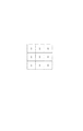
離散コサイン変換は、直交変換の一種であり、MPEG1や2などにおいて用いられている変換方法である(MPEGは8×8画素単位に固定されている)。その詳細を、図14を参照して説明する。図14(a)が4×4画素ブロックの入力画像であり、図14(b)が上記4×4画素ブロックに対して離散コサイン変換を行った後に出力される変換係数である。また、図14(c)が8×8画素ブロックの入力画像であり、図14(d)が上記8×8画素ブロックに対して離散コサイン変換を行った後に出力される変換係数である。 Discrete cosine transform is a kind of orthogonal transform and is a transform method used in MPEG1 and 2 (MPEG is fixed in units of 8 × 8 pixels). Details thereof will be described with reference to FIG. FIG. 14A shows an input image of a 4 × 4 pixel block, and FIG. 14B shows a transform coefficient output after performing a discrete cosine transform on the 4 × 4 pixel block. FIG. 14C shows an input image of an 8 × 8 pixel block, and FIG. 14D shows a transform coefficient output after performing a discrete cosine transform on the 8 × 8 pixel block.
4×4画素ブロックに対して離散コサイン変換を行った例について図14(a)及び(b)を参照して説明する。X11〜44が入力画像の画素値を示し、Y11〜44が離散コサイン変換係数を示す。ここで、A4を4×4離散コサイン変換行列、Xを入力画像信号、Yを離散コサイン変換係数の信号とすると、離散コサイン変換は、
[Y]=[A4][X][A4]T (式1)
で表わされる。
An example in which a discrete cosine transform is performed on a 4 × 4 pixel block will be described with reference to FIGS. 14 (a) and 14 (b). X 11 to 44 indicate pixel values of the input image, and Y 11 to 44 indicate discrete cosine transform coefficients. Here, when A 4 is a 4 × 4 discrete cosine transform matrix, X is an input image signal, and Y is a signal of a discrete cosine transform coefficient, the discrete cosine transform is
[Y] = [A 4 ] [X] [A 4 ] T (Formula 1)
It is represented by
ここで、 here,

とすれば、 given that,
となる。従って、式5及び図14(b)において、Y11、Y21、Y31、Y41の順で垂直方向空間周波数が高い変換係数となり、Y11、Y12、Y13、Y14の順で水平方向空間周波数が高い変換係数となる。 It becomes. Therefore, in Equation 5 and FIG. 14B, the vertical spatial frequency becomes a high conversion coefficient in the order of Y 11 , Y 21 , Y 31 , Y 41 , and in the order of Y 11 , Y 12 , Y 13 , Y 14 . The horizontal spatial frequency becomes a high conversion coefficient.
図14(c)及び図14(d)のように変換する8×8画素ブロックに対するときは、4×4画素のときに比べて変換係数の数が多いため空間周波数分解能が高いと言える。なお、式5の変換係数においてY11が入力画像のDC成分、Y11以外のY12〜Y44が入力画像のAC成分を表す離散コサイン変換係数である。 When the 8 × 8 pixel block is converted as shown in FIGS. 14C and 14D, it can be said that the spatial frequency resolution is high because the number of conversion coefficients is larger than that in the case of 4 × 4 pixels. In the transform coefficient of Expression 5, Y 11 is a DC component of the input image, and Y 12 to Y 44 other than Y 11 are discrete cosine transform coefficients representing the AC component of the input image.
以上が、離散コサイン変換についての説明である。 The above is an explanation of the discrete cosine transform.
続いて、図1の画像符号化装置の動作について説明する。本実施例における画像符号化装置は、入力画像の大きさに応じて適応的に符号化単位であるブロックの大きさを変更して、符号化処理を行うことが可能である。そして、変更可能なブロックの大きさとして4×4画素ブロックと8×8画素ブロックとがある。 Next, the operation of the image encoding device in FIG. 1 will be described. The image coding apparatus according to the present embodiment can perform coding processing by adaptively changing the size of a block that is a coding unit according to the size of an input image. Then, there are 4 × 4 pixel blocks and 8 × 8 pixel blocks as the sizes of blocks that can be changed.
また、入力画像として、大きさの異なる、1920×1080画素のHigh Definition画像(以下、HD画像と称す。)及び720×480画素のStandard Definition画像(以下、SD画像と称す)に対応する例を説明する。なお、本実施例の画像符号化装置の構成はこれに限ったものではなく、入力画像の大きさはHD画像/SD画像以外の大きさ(例えば、任意の解像度や画素数)に対応することも可能であり、ブロックの大きさは4×4画素/8×8画素以外(例えば、4×8画素や2×4画素など)にすることも可能である。また、離散コサイン変換の代わりに他の直交変換(例えば、整数変換やアダマール変換など)を用いて同様の機能を実現する変形例も考えられる。 In addition, as an input image, an example corresponding to a 1920 × 1080 pixel High Definition image (hereinafter referred to as an HD image) and a 720 × 480 pixel Standard Definition image (hereinafter referred to as an SD image) having different sizes is used. explain. Note that the configuration of the image coding apparatus according to the present embodiment is not limited to this, and the size of the input image corresponds to a size other than the HD image / SD image (for example, an arbitrary resolution and the number of pixels). The block size can be other than 4 × 4 pixels / 8 × 8 pixels (for example, 4 × 8 pixels, 2 × 4 pixels, etc.). Further, a modification in which a similar function is realized by using another orthogonal transform (for example, integer transform or Hadamard transform) instead of the discrete cosine transform is also conceivable.
図1において、まず、画像信号が入力されると、画像サイズ判定部102により入力画像の大きさが判定される。本構成例では入力画像がSD画像、HD画像のどちらであるかが判定されることになる。ブロックサイズ決定部103は、画像サイズ判定部102により判定された結果により、入力画像がSD画像のときはブロックの大きさを4×4画素に決定し、HD画像のときは8×8画素に決定する。ブロック構成部101は、ブロックサイズ決定部103により決定されたブロックの大きさに応じて、入力画像を分割してブロックを構成する。
In FIG. 1, first, when an image signal is input, the size of the input image is determined by the image size determination unit 102. In this configuration example, it is determined whether the input image is an SD image or an HD image. Based on the result of determination by the image size determination unit 102, the block
スイッチ106及び107は、前記ブロックサイズ決定部103により決定されたブロックの大きさが4×4画素の場合はAを選択、つまり、4×4離散コサイン変換部104での処理を選択し、8×8画素の場合はBを選択、つまり、8×8離散コサイン変換部105での処理を選択する。スイッチ106及び107により選択された4×4離散コサイン変換部104又は8×8離散コサイン変換部105は、それぞれ入力画像における各4×4画素ブロック又は各8×8画素ブロックに対して離散コサイン変換を行い、量子化部108に対して離散コサイン変換係数を出力する。量子化部108は入力した離散コサイン変換係数を量子化し、エントロピー符号化部109によりエントロピー符号化して、符号化データとして出力する。以上が、図1の画像符号化装置の動作説明である。
The
続いて、離散コサイン変換を行う際のブロックの大きさが圧縮後の画像に及ぼす影響について説明する。 Next, the influence of the block size when performing discrete cosine transform on the compressed image will be described.
ブロックの大きさはブロック歪みの見え方と、空間周波数分解能に影響を及ぼす。まず、ブロック歪みの見え方について、図2の原画像及び図3の復号画像を参照して説明する。 The block size affects the appearance of block distortion and the spatial frequency resolution. First, how the block distortion appears will be described with reference to the original image of FIG. 2 and the decoded image of FIG.
図2の原画像を圧縮し、伸張した復号画像の一部が図3である場合を考える。画像サイズは720×480画素のSD画像を例とする。以下、図2の太枠で囲んだ16×16画素ブロック201に対応する復号画像である16×16画素の図3(a)及び(b)を参照して説明する。図3(a)は4×4画素ブロックとして処理したときの図、図3(b)は8×8画素ブロックとして処理したときの図である。なお、図3(a)の太枠8×8画素ブロック内の4×4画素ブロックは、図3(a)のように301、302とする。
Consider a case where the original image of FIG. 2 is compressed and a part of the decompressed decoded image is FIG. As an example, the image size is an SD image of 720 × 480 pixels. Hereinafter, description will be made with reference to FIGS. 3A and 3B of 16 × 16 pixels which are decoded images corresponding to the 16 × 16
ブロック歪みは、量子化によりブロック境界の画素値が不連続になることにより発生する。つまり、ブロック歪みは離散コサイン変換を行ったブロック境界に発生する。その様子を模式的にあらわしたのが図3(a)及び(b)の復号画像である。水平、垂直の実線がブロック歪みを表している。図3(a)がブロックの大きさが4×4画素のときのブロック歪みを表し、図3(b)がブロックの大きさが8×8画素のときのブロック歪みを表している。図3(b)のブロックの大きさが8×8画素のときの方が、図3(a)の4×4画素のときに比べブロック歪みの大きさが大きいと言える。図3(a)及び(b)のような、ブロックの大きさを異ならせて圧縮処理した復号画像を、同性能の表示装置を用いて鑑賞したときには、ブロックの大きさが8×8画素のブロック歪みの方が、4×4画素のブロック歪みに比べブロック歪みが視覚的に目立ち易いということが言える。 Block distortion occurs due to discontinuous pixel values at block boundaries due to quantization. That is, block distortion occurs at the block boundary where the discrete cosine transform is performed. This is schematically shown in the decoded images of FIGS. 3 (a) and 3 (b). Horizontal and vertical solid lines represent block distortion. 3A shows block distortion when the block size is 4 × 4 pixels, and FIG. 3B shows block distortion when the block size is 8 × 8 pixels. It can be said that the block distortion is larger when the block size in FIG. 3B is 8 × 8 pixels than when it is 4 × 4 pixels in FIG. When a decoded image that has been compressed with different block sizes as shown in FIGS. 3A and 3B is viewed using a display device having the same performance, the block size is 8 × 8 pixels. It can be said that the block distortion is visually more noticeable than the block distortion of 4 × 4 pixels.
続いて、空間周波数分解能について図3(a)及び(b)を参照して説明する。 Next, the spatial frequency resolution will be described with reference to FIGS. 3 (a) and 3 (b).
図3(a)の場合では、4×4離散コサイン変換を行っているため前述のように空間周波数分解能が低い。そのため4×4画素ブロック301のような空間周波数が低い平坦な絵柄の復号画像はぼけ難いが、4×4画素ブロック302のような空間周波数が高い複雑な絵柄の復号画像はぼけ易くなってしまう。一方、図3(b)の場合では8×8離散コサイン変換を行っているので、空間周波数分解能が高く、ブロックの大きさが図3(a)のような4×4画素の場合に比べて、複雑な絵柄の復号画像はぼけ難いと言える。
In the case of FIG. 3A, since the 4 × 4 discrete cosine transform is performed, the spatial frequency resolution is low as described above. Therefore, a decoded image with a flat picture with a low spatial frequency like the 4 × 4
以上のことより、画像サイズが固定と仮定すると、離散コサイン変換を行うブロックの大きさを大きくするとブロック歪みは視覚的に目立ち易くなるが、複雑な絵柄の復号画像はぼけ難くなり、離散コサイン変換を行うブロックの大きさを小さくするとブロック歪みは視覚的に目立ち難くなるが、複雑な絵柄の復号画像はぼけ易くなるということが言える。 From the above, assuming that the image size is fixed, block distortion becomes visually noticeable when the block size for discrete cosine transform is increased, but the decoded image of a complex picture becomes difficult to blur, and discrete cosine transform It can be said that if the size of the block to be performed is reduced, the block distortion becomes visually inconspicuous, but a decoded image with a complicated pattern is easily blurred.
ここで、同一被写体であるが大きさの異なるSD画像とHD画像を圧縮伸張し、同一画像サイズで復号画像を表示する場合について図2、4及び5を参照して説明する。図2はSD原画像であり、図4はHD原画像である。なお、HD画像の方がSD画像に比べ画素密度が高いことに注意する。 Here, a case where an SD image and an HD image of the same subject but different sizes are compressed and decompressed and a decoded image is displayed with the same image size will be described with reference to FIGS. 2 is an SD original image, and FIG. 4 is an HD original image. Note that the HD image has a higher pixel density than the SD image.
図5(a)はSD画像である図2の太枠で囲んだ16×16画素ブロック201に対応する16×16画素の復号画像であり、ブロックの大きさを4×4画素として圧縮伸張を行っている。図5(b)はHD画像である図4の太枠で囲んだ32×32画素ブロック401に対応する32×32画素の復号画像であり、ブロックの大きさを8×8画素として圧縮伸張を行っている。図5(a)と(b)のブロック歪みの大きさを比較すると、圧縮伸張時のブロックの大きさは異なるが、画素密度の違いによりブロック歪みの大きさはほぼ同じであると言える。また、周波数分解能を比較するとブロックの大きさが8×8画素である図5(b)の方が、ブロックの大きさが4×4画素である図5(a)よりも高いと言える。すなわち、図5(a)の太枠で囲んだ4×4画素ブロック501と、図5(b)の太枠で囲んだ8×8画素ブロック502のような、複雑な絵柄の画像において、ブロック歪みの目立ち具合は同等であるが、ブロックの大きさが8×8画素である図5(b)の方が、ブロックの大きさが4×4画素である図5(a)よりもぼけ難いということが言える。
FIG. 5A shows a 16 × 16 pixel decoded image corresponding to the 16 × 16
以上のことより、同一被写体の画像を圧縮伸張し、同一画像サイズで復号画像を表示する場合では、HD画像を圧縮伸張する場合は、SD画像を圧縮伸張する場合よりブロックの大きさを大きくした方がぼけ難い復号画像が得られるということが言える。このような理由により、本発明の画像符号化装置におけるブロックサイズ決定部103は、画像サイズ判定部102の判定結果に応じて、入力画像がSD画像のときはブロックの大きさを4×4画素に決定し、HD画像のときは8×8画素に決定するのである。
As described above, when compressing / decompressing the same subject image and displaying the decoded image with the same image size, the block size is made larger when compressing / decompressing the HD image than when compressing / decompressing the SD image. It can be said that a decoded image that is less blurred is obtained. For this reason, the block
次に、これまで述べてきたような、入力画像の画像サイズに応じてブロックの大きさを適応的に変更した上で符号化を行う、本発明の画像符号化装置の処理手順について、図6のフローチャートを参照して説明する。 Next, the processing procedure of the image encoding apparatus according to the present invention for performing encoding after adaptively changing the block size according to the image size of the input image as described above will be described with reference to FIG. This will be described with reference to the flowchart of FIG.
まず、ステップ601において画像を入力する。次にステップ602において画像サイズ判定部102が入力した画像のサイズ(SD画像であるかHD画像であるか)を判定する。次にステップ603において、ステップ602において画像サイズ判定部102が判定した結果に応じて、ブロックサイズ決定部103は入力画像がSD画像のときはブロックの大きさを4×4画素とし、HD画像のときはブロックの大きさを8×8画素とするよう決定する。
First, in
次にステップ604において、ブロックサイズ決定部103により決定されたブロックの大きさを判断し、4×4画素のときはステップ605に移り、8×8画素のときはステップ607へ移る。
Next, in step 604, the block size determined by the block
次に、ブロックの大きさが4×4画素のときにはステップ605において、ブロック構成部101はブロックサイズ決定部103の結果に従って、入力画像を分割し4×4画素ブロックを構成する。そして、ステップ606において、4×4離散コサイン変換部104が構成された4×4画素ブロックに対して離散コサイン変換を行う。
Next, when the block size is 4 × 4 pixels, in
一方、ブロックの大きさが8×8画素のときにはステップ607において、ブロック構成部101はブロックサイズ決定部103の結果に従って、入力画像を分割し8×8画素ブロックを構成する。そして、ステップ608において、8×8離散コサイン変換部105が構成された8×8画素ブロックに対して離散コサイン変換を行う。
On the other hand, when the block size is 8 × 8 pixels, in
ステップ606またはステップ608において離散コサイン変換された変換係数は、ステップ609において量子化部108によって量子化され、ステップ610においてエントロピー符号化部109によってエントロピー符号化され、符号化データとして出力される。これで本フローは終了する。こうして出力された符号化データは不図示の記録再生装置で記録可能となり、これを再生する際に復号することで、復号画像を視聴可能となる。
The transform coefficient subjected to discrete cosine transform in
ここで、ステップ602における入力画像サイズの判定処理を、次のように変形しても良い。すなわち、画像サイズ判定部102は、ユーザーが指定した画像サイズやモード等に応じて判定するよう構成しても良い。例えば、本発明の画像符号化装置を搭載した撮像装置(ディジタルビデオカメラなど)において、撮影(記録)モード切替スイッチを「HD画像」にした場合は、これに連動して画像サイズ判定部102はHD画像と判定し、撮影モード切替スイッチを「SD画像」にした場合は、これに連動して画像サイズ判定部102はSD画像と判定するように構成しても良い。
Here, the input image size determination processing in
このように本実施例によれば、同一被写体の画像を圧縮伸張し、同一画像サイズで復号画像を表示する状況において、入力画像の大きさに応じてブロックの大きさを変更することにより、従来のブロックの大きさが固定されている場合に比べて、特に入力画像のサイズが大きいときでも複雑な絵柄の部分がぼけ難い復号画像を得ることが出来る。このことにより従来の技術に比べて画質の良い画像を得ることができる。 As described above, according to the present embodiment, in a situation where images of the same subject are compressed and expanded and a decoded image is displayed with the same image size, the block size is changed according to the size of the input image. Compared with the case where the size of the block is fixed, a decoded image in which a complicated picture portion is difficult to blur can be obtained even when the size of the input image is particularly large. As a result, it is possible to obtain an image with better image quality than the conventional technique.
次に、本発明の実施例2について説明する。実施例2における本発明の画像符号化装置は、現行のH.264符号化方式を拡張させた符号化方式で動画を圧縮符号化する構成が特徴となるものである。 Next, a second embodiment of the present invention will be described. The image encoding apparatus of the present invention in Embodiment 2 is the current H.264 standard. A feature is that a moving image is compression-encoded by an encoding method that is an extension of the H.264 encoding method.
ここで、そのH.264における画像符号化処理のブロック構成について、図12のブロック図を参照して説明する。図12の構成は、減算器1201、整数変換部1202、量子化部1203、エントロピー符号化部1204、逆量子化部1205、逆整数変換部1206、加算器1207、フレームメモリ1208及び1212、イントラ予測部1209、スイッチ1210及び1215、デブロッキングフィルタ1211、インター予測部1213、動き検出部1214から構成され、入力画像データを分割することによりブロックを構成し、ブロック単位にH.264符号化処理を行って、符号化データを出力する。
Here, the H.C. A block configuration of image encoding processing in H.264 will be described with reference to the block diagram of FIG. 12 includes a subtractor 1201, an
続いて、H.264の符号化処理について図12を参照してさらに説明する。 Subsequently, H.C. The H.264 encoding process will be further described with reference to FIG.
まず、減算器1201は、入力画像データから予測画像データを減算し、画像残差データを出力する。予測画像データの生成については後述する。 First, the subtractor 1201 subtracts the predicted image data from the input image data, and outputs image residual data. The generation of predicted image data will be described later.
整数変換部1202は、減算器1201から出力された画像残差データを直交変換処理して変換係数を出力する。そして、量子化部1203は上記変換係数を所定の量子化パラメータを用いて量子化する。
The
エントロピー符号化部1204は、量子化部1203で量子化された変換係数を入力し、これをエントロピー符号化して符号化データとして出力する。
The
一方、量子化部1203で量子化された変換係数は予測画像データの生成にも使われる。逆量子化部1205は、量子化部1203で量子化された変換係数を逆量子化する。さらに、逆整数変換部1206は逆量子化部1205で逆量子化された変換係数を逆整数変換し、復号画像残差データとして出力する。加算器1207は、復号画像残差データと予測画像データとを加算し、再構成画像データとして出力する。
On the other hand, the transform coefficient quantized by the
再構成画像データはフレームメモリ1208に記録されるとともに、デブロッキングフィルタ処理を行う場合はデブロッキングフィルタ1211を介して、デブロッキングフィルタ処理を行わない場合はデブロッキングフィルタ1211を介さずフレームメモリ1212に記録される。スイッチ1210は、デブロッキングフィルタ処理を行うか行わないか選択する選択部である。再構成画像データの中で、以降の予測で参照される可能性があるデータは、フレームメモリ1208または1212に暫くの期間保存される。また、デブロッキングフィルタ1211はノイズを除去する為に用いられる。 The reconstructed image data is recorded in the frame memory 1208, and when the deblocking filter process is performed, the deblocking filter 1211 is used. When the deblocking filter process is not performed, the deblocking filter 1211 is not stored in the frame memory 1212. To be recorded. The switch 1210 is a selection unit that selects whether to perform deblocking filter processing. Among the reconstructed image data, data that may be referred to in the subsequent prediction is stored in the frame memory 1208 or 1212 for a period of time. The deblocking filter 1211 is used to remove noise.
イントラ予測部1209は、フレームメモリ1208に記録された再構成画像データを用いてフレーム内予測処理を行い、予測画像データを生成する。また、インター予測部1213は、フレームメモリ1212に記録された再構成画像データを用いて、動き検出部1214によって検出された動きベクトル情報に基づいてフレーム間予測処理を行い、予測画像データを生成する。動き検出部1214は入力画像データにおける動きベクトルを検出し、検出した動きベクトル情報をインター予測部1213とエントロピー符号化部1204へ出力する。
The
スイッチ1215は、イントラ予測、インター予測のどちらを用いるか選択するための選択部である。イントラ予測部1209からの出力とインター予測部1213からの出力の一方を選択して、選択された予測画像データを減算器1201と加算器1207へ出力する。以上が図12に示した構成によるH.264の符号化処理に関する説明である。
The switch 1215 is a selection unit for selecting whether to use intra prediction or inter prediction. One of the output from the
ここで、H.264におけるデブロッキングフィルタについて説明する。H.264符号化方式では、図12でデブロッキングフィルタ1211として示したように、MPEG1や2とは異なり局部復号化された局部復号画像に対してフィルタ処理を行うデブロッキングフィルタを設けることが規定されている。このデブロッキングフィルタ1211は、ブロック境界に対して平滑化を行い、復号画像におけるブロック歪みを除去するとともに、動き補償処理により復号画像を参照する画像にブロック歪みが伝播するのを防ぐという目的を有する。より詳しくは、ITU−T H.264/ISO/IEC MPEG−4 Part 10のISO/IEC 14496−10の文献に記されている。
Here, H. A deblocking filter in H.264 will be described. H. In the H.264 encoding method, as shown as the deblocking filter 1211 in FIG. 12, it is specified that a deblocking filter for performing a filtering process on a locally decoded image, which is different from MPEG1 and 2, is provided. Yes. The deblocking filter 1211 has a purpose of smoothing the block boundary and removing block distortion in the decoded image, and preventing the block distortion from propagating to an image that references the decoded image by motion compensation processing. . More specifically, ITU-TH H.264 / ISO / IEC MPEG-4
次に、H.264における整数変換について説明する。MPEG1や2では、8×8画素単位の離散コサイン変換を用いた符号化を行うのに対して、H.264符号化方式では、図12で整数変換部1202として示したように、整数変換を用いた符号化を行う。
Next, H.I. The integer conversion in H.264 will be described. In MPEG1 and 2, encoding is performed using discrete cosine transform in units of 8 × 8 pixels. In the H.264 encoding method, encoding using integer conversion is performed as shown as the
以下に、H.264において用いられている整数変換について説明する。前述した離散コサイン変換の式5を変形すると、 H. The integer conversion used in H.264 will be described. By transforming Equation 5 of the discrete cosine transform described above,
のようになる。H.264の整数変換では、 become that way. H. For H.264 integer conversion,
を整数変換行列として用いており、下記の式7を整数変換と規定している。 Is used as an integer transformation matrix, and the following Equation 7 is defined as an integer transformation.
この整数変換は加算及びシフトにより演算可能となっている。また、 This integer conversion can be calculated by addition and shift. Also,
の項については、4×4画素ブロックの成分ごとに異なる量子化処理を行うことで演算を行う。すなわち、整数変換と量子化処理の組み合わせにより直交変換を実現していると言える。より詳しくは、ITU−T H.264/ISO/IEC MPEG−4 Part 10のISO/IEC 14496−10の文献に記されている。
For the term, the calculation is performed by performing different quantization processing for each component of the 4 × 4 pixel block. That is, it can be said that orthogonal transformation is realized by a combination of integer transformation and quantization processing. More specifically, ITU-TH H.264 / ISO / IEC MPEG-4
このような、H.264符号化方式を用いた画像符号化装置を構成した場合であっても、実施例1にて説明したような、入力画像サイズに応じて符号化時のブロックの大きさを変更するといった本発明の構成を適用可能となる。ただし、現行のH.264においては、整数変換を行うブロックの大きさは4×4画素ブロックに固定されているので、この点を拡張させて少なくとも8×8画素ブロックも処理可能とした場合を前提とする。 H. Even when an image encoding apparatus using the H.264 encoding method is configured, the present invention changes the block size at the time of encoding according to the input image size as described in the first embodiment. The configuration of can be applied. However, the current H.C. In H.264, since the size of a block for performing integer conversion is fixed to a 4 × 4 pixel block, it is assumed that at least an 8 × 8 pixel block can be processed by extending this point.
入力画像の画像サイズに応じてブロックの大きさを適応的に変更した上で符号化を行う、本発明の画像符号化装置の処理手順について、図13のフローチャートを参照して説明する。 A processing procedure of the image coding apparatus of the present invention that performs coding after adaptively changing the block size according to the image size of the input image will be described with reference to the flowchart of FIG.
まず、ステップ1301において画像を入力する。次にステップ1302において入力画像のサイズ(SD画像であるかHD画像であるか)を不図示のマイクロコンピュータ等の判定手段で判定する。または、ユーザーが「SD画像」又は「HD画像」を選択した指示に従って不図示のマイクロコンピュータで同様に判定しても良い。
First, in
次にステップ1303において、ステップ1302における判定結果に応じて、不図示のマイクロコンピュータ等の設定手段が入力画像がSD画像のときはブロックの大きさを4×4画素とし、HD画像のときはブロックの大きさを8×8画素とするよう決定する。
Next, in step 1303, according to the determination result in
次にステップ1304において、ステップ1303で決定されたブロックの大きさを判断し、4×4画素のときはステップ1305に移り、8×8画素のときはステップ1307へ移る。
Next, in
次に、ブロックの大きさが4×4画素のときには、ステップ1305において入力画像を分割し4×4画素ブロックを構成した上で、ステップ1306において整数変換部1202が各4×4画素ブロックに対して整数変換を行う。
Next, when the block size is 4 × 4 pixels, the input image is divided in
一方、ブロックの大きさが8×8画素のときには、ステップ1307において入力画像を分割し8×8画素ブロックを構成した上で、ステップ1308において整数変換部1202が各8×8画素ブロックに対して整数変換を行う。
On the other hand, when the block size is 8 × 8 pixels, the input image is divided in step 1307 to form an 8 × 8 pixel block, and then in step 1308, the
ステップ1306またはステップ1308において整数変換された変換係数は、ステップ1309において量子化部1203によって量子化され、ステップ1310においてエントロピー符号化部1204によってエントロピー符号化され、符号化データとして出力される。これで本フローは終了する。こうして出力された符号化データは不図示の記録再生装置で記録可能となり、これを再生する際に復号することで、復号画像を視聴可能となる。
The transform coefficient subjected to the integer transform in
このように本実施例によれば、実施例1と同様に、従来のブロックの大きさが固定されている場合に比べて、特に入力画像のサイズが大きいときでも複雑な絵柄の部分がぼけ難い復号画像を得ることが出来る。このことにより従来の技術に比べて画質の良い画像を得ることができる。そして、H.264符号化におけるブロックの大きさを可変させて符号化処理することにより、画質の向上が実現できるとともに、8×8画素に対応することによる符号化処理の効率化も期待できる。 As described above, according to the present embodiment, as in the first embodiment, compared to the conventional case where the block size is fixed, even when the size of the input image is large, it is difficult to blur a complicated pattern portion. A decoded image can be obtained. As a result, it is possible to obtain an image with better image quality than the conventional technique. And H. By performing the encoding process by changing the block size in H.264 encoding, it is possible to improve the image quality and to expect the efficiency of the encoding process by supporting 8 × 8 pixels.
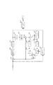
次に、本発明の実施例3について図面を参照しながら説明する。図7は本実施例における、撮像装置等で用いて好適な画像符号化装置のブロック図である。なお、図7の画像符号化装置は、実施例1で説明した図1の画像符号化装置の構成に加えて、構成したブロックの大きさに従ってデブロッキングフィルタの処理を変更する構成を備えたことを特徴としている。なお、図7のブロック図において、図1のブロック図と同じ符号を付してあるブロックに関しては、それぞれ同様の構成及び機能となるものであり、図1で行った説明と重複するのでここでの説明は省略する。 Next, Embodiment 3 of the present invention will be described with reference to the drawings. FIG. 7 is a block diagram of an image encoding apparatus suitable for use in an imaging apparatus or the like in this embodiment. In addition to the configuration of the image encoding device in FIG. 1 described in the first embodiment, the image encoding device in FIG. 7 has a configuration for changing the processing of the deblocking filter according to the size of the configured block. It is characterized by. In the block diagram of FIG. 7, blocks having the same reference numerals as those in the block diagram of FIG. 1 have the same configuration and function, and are redundant with the explanation given in FIG. 1. Description of is omitted.
まず、図7の画像符号化装置の構成について説明する。図7において、701は入力画像から予測画像を差分する減算器である。702は逆量子化部、703は4×4画素ブロックに対して逆離散コサイン変換を行う4×4逆離散コサイン変換部、704は8×8画素ブロックに対して逆離散コサイン変換を行う8×8逆離散コサイン変換部である。705及び706はスイッチであり、4×4逆離散コサイン変換部703(A側のスイッチの経路)、或いは、8×8逆離散コサイン変換部704(B側のスイッチの経路)を選択する選択部である。 First, the configuration of the image encoding device in FIG. 7 will be described. In FIG. 7, reference numeral 701 denotes a subtracter for subtracting a predicted image from an input image. 702 is an inverse quantization unit, 703 is a 4 × 4 inverse discrete cosine transform unit that performs an inverse discrete cosine transform on a 4 × 4 pixel block, and 704 is an 8 × that performs an inverse discrete cosine transform on an 8 × 8 pixel block. 8 is an inverse discrete cosine transform unit. 705 and 706 are switches, and a selection unit that selects the 4 × 4 inverse discrete cosine transform unit 703 (A-side switch path) or the 8 × 8 inverse discrete cosine transform unit 704 (B-side switch path). It is.
707は復号画像の残差データと予測画像とを加算し再構成画像を出力する加算器である。708は4×4画素ブロックに対して後述のフィルタ処理を行う4×4デブロッキングフィルタ部であり、709は8×8画素ブロックに対して後述のフィルタ処理を行う8×8デブロッキングフィルタ部である。710及び711はスイッチであり、4×4デブロッキングフィルタ部708(A側のスイッチの経路)、或いは、8×8デブロッキングフィルタ部709(B側のスイッチの経路)を選択する選択部である。 Reference numeral 707 denotes an adder that adds the residual data of the decoded image and the predicted image and outputs a reconstructed image. Reference numeral 708 denotes a 4 × 4 deblocking filter unit that performs a later-described filter process on the 4 × 4 pixel block, and reference numeral 709 denotes an 8 × 8 deblocking filter unit that performs a later-described filter process on the 8 × 8 pixel block. is there. Reference numerals 710 and 711 denote switches, which are selection units for selecting the 4 × 4 deblocking filter unit 708 (A-side switch path) or the 8 × 8 deblocking filter unit 709 (B-side switch path). .
712は再構成画像を記録するフレームメモリ、713はフレーム間予測を行うインター予測部、714はフレーム間の動きを検出する動き検出部である。以上が図7の構成である。 Reference numeral 712 denotes a frame memory that records a reconstructed image, 713 denotes an inter prediction unit that performs inter-frame prediction, and 714 denotes a motion detection unit that detects a motion between frames. The above is the configuration of FIG.
続いて、図7の画像符号化装置の動作について説明する。 Next, the operation of the image encoding device in FIG. 7 will be described.
まず、減算器701は入力画像から予測画像を減算し、画像の残差データを出力する。予測画像の生成については後述する。量子化部108で量子化された変換係数はエントロピー符号化部109でエントロピー符号化されるとともに、逆量子化部702において逆量子化される。
First, the subtractor 701 subtracts the predicted image from the input image, and outputs image residual data. The generation of the predicted image will be described later. The transform coefficient quantized by the
スイッチ705及び706はブロックサイズ決定部103により決定されたブロックの大きさに応じて、ブロックが4×4画素の場合はAを選択、つまり、4×4逆離散コサイン変換部703での処理を選択し、8×8画素の場合はBを選択、つまり、8×8逆離散コサイン変換部704での処理を選択するよう動作する。スイッチ705及び706で選択された4×4逆離散コサイン変換部703又は8×8離散コサイン変換部704は、それぞれ4×4画素ブロック又は8×8画素ブロックに対して逆離散コサイン変換を行って、復号画像の残差データを出力する。
The switches 705 and 706 select A according to the block size determined by the block
加算器707は、復号画像の残差データと予測画像とを加算し、再構成画像として出力する。 The adder 707 adds the residual data of the decoded image and the predicted image, and outputs the result as a reconstructed image.
スイッチ710及び711はブロックサイズ決定部103により決定されたブロックの大きさに応じて、ブロックが4×4画素の場合はAを選択、つまり、4×4デブロッキングフィルタ部708での処理を選択し、8×8画素の場合はBを選択、つまり、8×8デブロッキングフィルタ部709での処理を選択するよう動作する。スイッチ710及び711で選択された4×4デブロッキングフィルタ部708又は8×8デブロッキングフィルタ部709は、再構成画像データを入力してそれぞれ4×4画素ブロック又は8×8画素ブロックに対してデブロッキングフィルタ処理を行って、フィルタ処理後の再構成画像データをフレームメモリ712に記録する。
The switches 710 and 711 select A when the block is 4 × 4 pixels according to the block size determined by the block
また、インター予測部713は、フレームメモリ712に記録された再構成画像データを用いて、動き検出部714により検出された動きベクトル情報に基づいてフレーム間予測処理を行い、予測画像を生成する。以上が、図7の画像符号化装置の動作説明である。 In addition, the inter prediction unit 713 performs inter-frame prediction processing based on the motion vector information detected by the motion detection unit 714 using the reconstructed image data recorded in the frame memory 712, and generates a predicted image. The above is the description of the operation of the image encoding device in FIG.
続いて、図7の画像符号化装置におけるデブロッキングフィルタ処理について図8、図9、図10を参照して説明する。ここでは、デブロッキングフィルタ処理として3×3フィルターマスクを用いた平滑化フィルタ処理を行う例について説明する。ただし、デブロッキングフィルタ処理はこのフィルタ処理に限ったものではない。 Next, deblocking filter processing in the image encoding device in FIG. 7 will be described with reference to FIGS. 8, 9, and 10. Here, an example in which smoothing filter processing using a 3 × 3 filter mask is performed as deblocking filter processing will be described. However, the deblocking filter process is not limited to this filter process.
図8(a)のf(i,j)はフィルタ処理を行う注目画素値を示し(i及びjは整数)、フィルタ処理後の注目画素f(i,j)の新しい画素値g(i,j)(図8(b))は、フィルタ処理前の画像における注目画素を取り巻く3×3フィルターマスク上の画素値、すなわち、図8(a)のf(i−1,j−1),f(i,j−1),f(i+1,j−1),f(i−1,j),f(i,j),f(i+1,j),f(i−1,j+1),f(i,j+1),およびf(i+1,j+1)の9個の値を用いて決定される。 In FIG. 8A, f (i, j) indicates a target pixel value to be filtered (i and j are integers), and a new pixel value g (i, j) of the target pixel f (i, j) after the filter processing. j) (FIG. 8B) is a pixel value on the 3 × 3 filter mask surrounding the pixel of interest in the image before filtering, that is, f (i−1, j−1), FIG. f (i, j-1), f (i + 1, j-1), f (i-1, j), f (i, j), f (i + 1, j), f (i-1, j + 1), It is determined using nine values of f (i, j + 1) and f (i + 1, j + 1).
続いて、3×3フィルターマスクを用いたフィルタ処理について図9を参照して説明する。なお、図9に示す数字はそれぞれの位置に対応する画素値にかけるフィルタ係数を表す。 Next, filter processing using a 3 × 3 filter mask will be described with reference to FIG. Note that the numbers shown in FIG. 9 represent filter coefficients applied to pixel values corresponding to the respective positions.
図9のような3×3フィルターマスクを用いたフィルタ処理の場合のフィルタ処理後の画素値g(i,j)は、 The pixel value g (i, j) after the filter processing in the case of the filter processing using the 3 × 3 filter mask as shown in FIG.
で表される。このフィルタ処理を行うことにより注目画素と注目画素の周囲の画素値との差分が小さくなる。 It is represented by By performing this filtering process, the difference between the pixel of interest and the pixel values around the pixel of interest is reduced.
続いて、フィルタ処理を行う画素について図10を参照して説明する。図10(a)及び(b)は1フレームの画像のある部分を拡大したものであり、太線で囲まれた領域がブロックであり、そのブロック内の小さい正方形は1画素を表す。図10(a)はブロックの大きさが8×8画素の場合であり、図10(b)はブロックの大きさが4×4画素の場合である。ここではブロックの大きさが8×8画素の場合のフィルタ処理について図10(a)を参照して説明する。 Next, the pixel that performs the filtering process will be described with reference to FIG. 10A and 10B are enlarged views of a portion of an image of one frame. A region surrounded by a thick line is a block, and a small square in the block represents one pixel. FIG. 10A shows a case where the block size is 8 × 8 pixels, and FIG. 10B shows a case where the block size is 4 × 4 pixels. Here, filter processing when the block size is 8 × 8 pixels will be described with reference to FIG.
図10(a)の網線部で示したある1つの画素を注目画素f(i,j)として前述のフィルタ処理を行う。この処理をすべての網線部の画素、つまり、8×8画素ブロックのブロック境界画素に対して行う。このように8×8画素ブロックのブロック境界画素に対しフィルタ処理を行うことにより、ブロック境界画素値の差分が小さくなりブロック歪みを低減させることができる。ブロックの大きさが4×4画素の場合も同様に図10(b)の網線部で示したある1つの画素を注目画素f(i,j)として前述のフィルタ処理を行う。 The above-described filtering process is performed with one pixel indicated by the halftone line portion in FIG. 10A as the target pixel f (i, j). This process is performed on all the pixels of the net line portion, that is, the block boundary pixels of the 8 × 8 pixel block. Thus, by performing the filter processing on the block boundary pixels of the 8 × 8 pixel block, the difference between the block boundary pixel values is reduced, and the block distortion can be reduced. Similarly, when the block size is 4 × 4 pixels, the above-described filtering process is performed with one pixel indicated by the halftone line portion in FIG. 10B as the target pixel f (i, j).
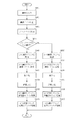
次に、これまで述べてきたような、入力画像の画像サイズに応じてブロックの大きさを適応的に変更した上で符号化し、さらに逆離散コサイン変換やデブロッキングフィルタでの処理も変更されたブロックサイズに応じて変更するといった、本発明の画像符号化装置の処理手順について、図11のフローチャートを参照して説明する。なお、図11のフローチャートのうち、図6のフローチャートの各ステップと同符号を付してあるステップに関しては、図6と同様の説明になるので、ここでの説明は省略する。 Next, as described above, encoding was performed after adaptively changing the block size according to the image size of the input image, and further, processing by inverse discrete cosine transform and deblocking filter was also changed. The processing procedure of the image coding apparatus according to the present invention, such as changing according to the block size, will be described with reference to the flowchart of FIG. In the flowchart of FIG. 11, the steps denoted by the same reference numerals as those of the flowchart of FIG. 6 are the same as those in FIG. 6, and thus the description thereof is omitted here.
まず、前述のようにステップ601〜ステップ609において、入力画像サイズに応じたブロックの大きさが決定され、ブロックの大きさに応じた離散コサイン変換が行われ、量子化が行われる。
First, in
そして、ブロックの大きさが4×4画素の場合、ステップ1101において逆量子化部702は、量子化部108によって量子化された変換係数を逆量子化する。次に、ステップ1102において、4×4逆離散コサイン変換部703によって4×4画素ブロックに対して逆離散コサイン変換が行われ、さらにステップ1103において、4×4デブロッキングフィルタ部708によって4×4画素ブロック境界に対してデブロッキングフィルタ処理が行われる。
If the block size is 4 × 4 pixels, the inverse quantization unit 702 performs inverse quantization on the transform coefficient quantized by the
また、ブロックの大きさが8×8画素の場合は、ステップ1101において逆量子化部702は、量子化部108によって量子化された変換係数を逆量子化する。次に、ステップ1104において、8×8逆離散コサイン変換部704によって8×8画素ブロックに対して逆離散コサイン変換が行われ、さらにステップ1105において、8×8デブロッキングフィルタ部709によって8×8画素ブロック境界に対してデブロッキングフィルタ処理が行われる。
If the block size is 8 × 8 pixels, the inverse quantization unit 702 dequantizes the transform coefficient quantized by the
デブロッキングフィルタ処理が行われた後は、前述したような動作手順でインター予測等が行われ、その結果符号化データが出力されることになる。以上で本フローは終了する。このような符号化処理により出力された符号化データは不図示の記録再生装置で記録可能となり、これを再生する際に復号することで、復号画像を視聴可能となる。 After the deblocking filter process is performed, inter prediction or the like is performed according to the operation procedure described above, and as a result, encoded data is output. This flow is completed. The encoded data output by such an encoding process can be recorded by a recording / reproducing apparatus (not shown), and the decoded image can be viewed by decoding it when reproducing it.
なお、実施例1と同様に、ステップ602における入力画像サイズの判定処理を、次のように変形しても良い。すなわち、画像サイズ判定部102は、ユーザーが指定した画像サイズに応じて判定するよう構成しても良い。例えば、本発明の画像符号化装置を搭載した撮像装置(ディジタルビデオカメラなど)において、撮影(記録)モード切替スイッチを「HD画像」にした場合は、これに連動して画像サイズ判定部102はHD画像と判定し、撮影モード切替スイッチを「SD画像」にした場合は、これに連動して画像サイズ判定部102はSD画像と判定するように構成しても良い。さらに本実施例では、この判定結果に応じて決定されたブロックサイズに従って、逆離散コサイン変換やデブロッキングフィルタでの処理も前述したように変更されることになる。
As in the first embodiment, the input image size determination process in
このように本実施例によれば、入力画像の大きさに応じてブロックの大きさを変更することにより、従来のブロックの大きさが固定されている場合に比べて、特に入力画像のサイズが大きいときでも複雑な絵柄の部分がぼけ難い復号画像を得ることが出来る。さらに、変更されたブロックの大きさに従って、フィルタ処理を行うブロックの大きさを変更させることにより、ブロック歪みの発生が予想される部分のみに適切なフィルタ処理を行うことができる。これにより効果的にブロック歪みを低減した画質の良い画像を得ることができる。 Thus, according to the present embodiment, by changing the block size according to the size of the input image, the size of the input image is particularly large compared to the case where the size of the conventional block is fixed. Even when it is large, it is possible to obtain a decoded image in which a complicated pattern portion is difficult to blur. Furthermore, by changing the size of the block on which the filtering process is performed according to the changed block size, it is possible to perform an appropriate filtering process only on a portion where occurrence of block distortion is expected. As a result, it is possible to effectively obtain an image with good image quality with reduced block distortion.
Claims (17)
入力画像を分割してブロックを構成するブロック構成手段と、
前記ブロック構成手段に大きさが異なる画像を入力可能な入力手段と、
前記入力手段により入力される画像の大きさを判定する画像サイズ判定手段と、
前記画像サイズ判定手段により判定された画像の大きさに応じて、前記ブロック構成手段により構成されるブロックのサイズを決定するブロックサイズ決定手段とを備えたことを特徴とする画像符号化装置。 In an image encoding device that performs encoding processing in units of blocks,
Block configuration means for dividing the input image to form blocks;
Input means capable of inputting images of different sizes into the block constituting means;
Image size determination means for determining the size of an image input by the input means;
An image encoding apparatus comprising: a block size determination unit that determines a size of a block configured by the block configuration unit according to an image size determined by the image size determination unit.
HD画像データ及びSD画像データを入力可能な入力手段と、
前記入力手段により入力された画像データがHD画像であるかSD画像であるかを判定する画像サイズ判定手段と、
前記画像サイズ判定手段により判定された結果がHD画像のときとSD画像のときとで、異なるブロックサイズを決定するブロックサイズ決定手段と、
前記ブロックサイズ決定手段で決定されたブロックサイズに応じて、前記入力された画像データを分割してブロックを構成するブロック構成手段と、
前記ブロック構成手段によって構成されたブロック単位で直交変換を行う直交変換手段と、
前記直交変換されたデータを量子化する量子化手段と、
前記量子化されたデータを符号化する符号化手段とを備えることを特徴とする画像符号化装置。 In an image encoding device that performs encoding processing in units of blocks,
Input means capable of inputting HD image data and SD image data;
Image size determination means for determining whether the image data input by the input means is an HD image or an SD image;
Block size determining means for determining different block sizes depending on whether the result determined by the image size determining means is an HD image or an SD image;
A block configuration unit configured to divide the input image data and configure a block according to the block size determined by the block size determination unit;
Orthogonal transform means for performing orthogonal transform in units of blocks configured by the block configuration means;
Quantization means for quantizing the orthogonally transformed data;
An image encoding apparatus comprising: encoding means for encoding the quantized data.
入力画像を分割してブロックを構成するブロック構成ステップと、
大きさが異なる画像を入力可能な入力ステップと、
前記入力ステップにより入力される画像の大きさを判定する画像サイズ判定ステップと、
前記画像サイズ判定ステップにより判定された画像の大きさに応じて、前記ブロック構成ステップにより構成されるブロックのサイズを決定するブロックサイズ決定ステップとを有することを特徴とする画像符号化方法。 In an image encoding method that performs an encoding process in units of blocks,
A block configuration step for dividing the input image to form a block;
An input step capable of inputting images of different sizes;
An image size determination step for determining the size of the image input in the input step;
An image encoding method comprising: a block size determination step for determining a size of a block configured by the block configuration step according to an image size determined by the image size determination step.
HD画像データ及びSD画像データを入力可能な入力ステップと、
前記入力ステップにより入力された画像データがHD画像であるかSD画像であるかを判定する画像サイズ判定ステップと、
前記画像サイズ判定ステップにより判定された結果がHD画像のときとSD画像のときとで、異なるブロックサイズを決定するブロックサイズ決定ステップと、
前記ブロックサイズ決定ステップで決定されたブロックサイズに応じて、前記入力された画像データを分割してブロックを構成するブロック構成ステップと、
前記ブロック構成ステップによって構成されたブロック単位で直交変換を行う直交変換ステップと、
前記直交変換されたデータを量子化する量子化ステップと、
前記量子化されたデータを符号化する符号化ステップとを有することを特徴とする画像符号化方法。 In an image encoding method that performs an encoding process in units of blocks,
An input step capable of inputting HD image data and SD image data;
An image size determination step for determining whether the image data input in the input step is an HD image or an SD image;
A block size determination step for determining different block sizes depending on whether the result determined in the image size determination step is an HD image or an SD image;
In accordance with the block size determined in the block size determination step, a block configuration step that divides the input image data to configure a block;
An orthogonal transform step for performing orthogonal transform in units of blocks configured by the block configuration step;
A quantization step for quantizing the orthogonally transformed data;
And a coding step for coding the quantized data.
Priority Applications (3)
| Application Number | Priority Date | Filing Date | Title |
|---|---|---|---|
| JP2004345281A JP2006157481A (en) | 2004-11-30 | 2004-11-30 | Image coding apparatus and method thereof |
| US11/286,723 US7706622B2 (en) | 2004-11-30 | 2005-11-23 | Image coding apparatus and image coding method |
| CNB2005101261391A CN100534184C (en) | 2004-11-30 | 2005-11-30 | Image coding apparatus and image coding method |
Applications Claiming Priority (1)
| Application Number | Priority Date | Filing Date | Title |
|---|---|---|---|
| JP2004345281A JP2006157481A (en) | 2004-11-30 | 2004-11-30 | Image coding apparatus and method thereof |
Publications (2)
| Publication Number | Publication Date |
|---|---|
| JP2006157481A true JP2006157481A (en) | 2006-06-15 |
| JP2006157481A5 JP2006157481A5 (en) | 2008-01-17 |
Family
ID=36567458
Family Applications (1)
| Application Number | Title | Priority Date | Filing Date |
|---|---|---|---|
| JP2004345281A Pending JP2006157481A (en) | 2004-11-30 | 2004-11-30 | Image coding apparatus and method thereof |
Country Status (3)
| Country | Link |
|---|---|
| US (1) | US7706622B2 (en) |
| JP (1) | JP2006157481A (en) |
| CN (1) | CN100534184C (en) |
Cited By (7)
| Publication number | Priority date | Publication date | Assignee | Title |
|---|---|---|---|---|
| JP2008061044A (en) * | 2006-08-31 | 2008-03-13 | Fujitsu Ltd | Image encoding apparatus and encoding method |
| JPWO2007034918A1 (en) * | 2005-09-26 | 2009-03-26 | 三菱電機株式会社 | Video encoding apparatus and video decoding apparatus |
| JP2009164915A (en) * | 2008-01-08 | 2009-07-23 | Nippon Telegr & Teleph Corp <Ntt> | Image encoding method, image decoding method, image encoder, image decoder, and image encoding program, image decoding program, and computer-readable recording medium recording the programs |
| WO2009110559A1 (en) * | 2008-03-07 | 2009-09-11 | 株式会社 東芝 | Dynamic image encoding/decoding device |
| WO2009122759A1 (en) * | 2008-04-04 | 2009-10-08 | 富士フイルム株式会社 | Image processing system, image processing method, and computer-readable medium |
| JP2015002368A (en) * | 2013-06-13 | 2015-01-05 | キヤノン株式会社 | Image encoder, image coding method and program |
| KR101760420B1 (en) | 2011-01-04 | 2017-07-21 | 엘지전자 주식회사 | Apparatus and method for processing sharpness of video signal, Broadcasting Signal Receiver |
Families Citing this family (29)
| Publication number | Priority date | Publication date | Assignee | Title |
|---|---|---|---|---|
| CN102197650A (en) * | 2008-10-27 | 2011-09-21 | 松下电器产业株式会社 | Method for coding image, image coding device and image pickup system |
| KR20170116216A (en) * | 2009-01-27 | 2017-10-18 | 톰슨 라이센싱 | Methods and apparatus for transform selection in video encoding and decoding |
| JP2010288080A (en) * | 2009-06-11 | 2010-12-24 | Sony Corp | Image processing apparatus and image processing method |
| KR101487687B1 (en) | 2010-01-14 | 2015-01-29 | 삼성전자주식회사 | Method and apparatus for encoding and decoding image using large transform unit |
| US9794556B2 (en) | 2010-02-17 | 2017-10-17 | Electronics And Telecommunications Research Institute | Method and device for simplifying encoding and decoding of ultra-high definition images |
| KR20110112168A (en) * | 2010-04-05 | 2011-10-12 | 삼성전자주식회사 | Method and apparatus for video encoding based on internal bitdepth increment, method and apparatus for video decoding based on internal bitdepth increment |
| US9369736B2 (en) | 2010-04-05 | 2016-06-14 | Samsung Electronics Co., Ltd. | Low complexity entropy-encoding/decoding method and apparatus |
| US8638863B1 (en) | 2010-05-18 | 2014-01-28 | Google Inc. | Apparatus and method for filtering video using extended edge-detection |
| MX2013003696A (en) * | 2010-09-30 | 2013-05-20 | Mitsubishi Electric Corp | Motion-video encoding apparatus, motion-video decoding apparatus, motion-video encoding method, and motion-video decoding method. |
| US9008175B2 (en) | 2010-10-01 | 2015-04-14 | Qualcomm Incorporated | Intra smoothing filter for video coding |
| US9210442B2 (en) | 2011-01-12 | 2015-12-08 | Google Technology Holdings LLC | Efficient transform unit representation |
| CN105959693B (en) * | 2011-01-13 | 2019-03-29 | 佳能株式会社 | Picture coding device and method and picture decoding apparatus and method |
| US9380319B2 (en) * | 2011-02-04 | 2016-06-28 | Google Technology Holdings LLC | Implicit transform unit representation |
| CA2833902C (en) * | 2011-06-24 | 2018-09-04 | Mitsubishi Electric Corporation | Image encoding device, image decoding device, image encoding method, image decoding method, and image prediction device |
| JP6120490B2 (en) | 2011-11-07 | 2017-04-26 | キヤノン株式会社 | Image encoding device, image encoding method and program, image decoding device, image decoding method and program |
| US9635359B2 (en) * | 2011-11-28 | 2017-04-25 | Canon Kabushiki Kaisha | Method and apparatus for determining deblocking filter intensity |
| US8675731B2 (en) * | 2012-08-13 | 2014-03-18 | Gurulogic Microsystems Oy | Encoder and method |
| US10333547B2 (en) | 2012-08-13 | 2019-06-25 | Gurologic Microsystems Oy | Encoder and method for encoding input data using a plurality of different transformations or combinations of transformations |
| US9219915B1 (en) | 2013-01-17 | 2015-12-22 | Google Inc. | Selection of transform size in video coding |
| US9967559B1 (en) | 2013-02-11 | 2018-05-08 | Google Llc | Motion vector dependent spatial transformation in video coding |
| US9544597B1 (en) | 2013-02-11 | 2017-01-10 | Google Inc. | Hybrid transform in video encoding and decoding |
| US9674530B1 (en) | 2013-04-30 | 2017-06-06 | Google Inc. | Hybrid transforms in video coding |
| JP6337380B2 (en) * | 2013-07-31 | 2018-06-06 | サン パテント トラスト | Image encoding method and image encoding apparatus |
| US9565451B1 (en) | 2014-10-31 | 2017-02-07 | Google Inc. | Prediction dependent transform coding |
| US9769499B2 (en) | 2015-08-11 | 2017-09-19 | Google Inc. | Super-transform video coding |
| US10277905B2 (en) | 2015-09-14 | 2019-04-30 | Google Llc | Transform selection for non-baseband signal coding |
| KR20180061273A (en) | 2015-09-30 | 2018-06-07 | 리얼네트웍스 인코포레이티드 | Layered deblocking filtering in video processing systems and methods |
| US9807423B1 (en) | 2015-11-24 | 2017-10-31 | Google Inc. | Hybrid transform scheme for video coding |
| US11122297B2 (en) | 2019-05-03 | 2021-09-14 | Google Llc | Using border-aligned block functions for image compression |
Citations (4)
| Publication number | Priority date | Publication date | Assignee | Title |
|---|---|---|---|---|
| JPH05207440A (en) * | 1992-01-30 | 1993-08-13 | Matsushita Electric Ind Co Ltd | Code quantity controller |
| JPH07143483A (en) * | 1993-11-15 | 1995-06-02 | Nec Eng Ltd | Adaptive post-processing filter |
| JP2003250161A (en) * | 2001-12-19 | 2003-09-05 | Matsushita Electric Ind Co Ltd | Encoder and decoder |
| JP2003319394A (en) * | 2002-04-26 | 2003-11-07 | Sony Corp | Encoding apparatus and method, decoding apparatus and method, recording medium, and program |
Family Cites Families (19)
| Publication number | Priority date | Publication date | Assignee | Title |
|---|---|---|---|---|
| US5021891A (en) * | 1990-02-27 | 1991-06-04 | Qualcomm, Inc. | Adaptive block size image compression method and system |
| JP3156447B2 (en) | 1993-06-17 | 2001-04-16 | 富士通株式会社 | Semiconductor integrated circuit |
| US5610657A (en) * | 1993-09-14 | 1997-03-11 | Envistech Inc. | Video compression using an iterative error data coding method |
| KR0139164B1 (en) * | 1994-12-19 | 1998-06-01 | 김광호 | Adapted orthogonal transform coding apparatus |
| US6018368A (en) * | 1997-07-11 | 2000-01-25 | Samsung Electro-Mechanics Co., Ltd. | Scalable encoding apparatus and method with improved function of scaling motion vector |
| US6650361B1 (en) * | 1997-12-17 | 2003-11-18 | Canon Kabushiki Kaisha | Imaging apparatus control method, and a computer program product having computer program code therefor |
| JP4378804B2 (en) * | 1999-09-10 | 2009-12-09 | ソニー株式会社 | Imaging device |
| JP2001112000A (en) * | 1999-10-07 | 2001-04-20 | Matsushita Electric Ind Co Ltd | Video signal encoding device |
| JP3269056B2 (en) * | 2000-07-04 | 2002-03-25 | 松下電器産業株式会社 | Monitoring system |
| JP2002314870A (en) | 2001-04-17 | 2002-10-25 | Canon Inc | Imaging device, method, program, and computer-readable record medium |
| WO2003026350A2 (en) * | 2001-09-14 | 2003-03-27 | The Regents Of The University Of Michigan | Audio distributor |
| EP1322121A3 (en) * | 2001-12-19 | 2003-07-16 | Matsushita Electric Industrial Co., Ltd. | Video encoder and decoder with improved motion detection precision |
| JP4724351B2 (en) * | 2002-07-15 | 2011-07-13 | 三菱電機株式会社 | Image encoding apparatus, image encoding method, image decoding apparatus, image decoding method, and communication apparatus |
| JP4806888B2 (en) | 2002-07-19 | 2011-11-02 | ソニー株式会社 | Decoding device and decoding method |
| JP2004128587A (en) * | 2002-09-30 | 2004-04-22 | Minolta Co Ltd | Digital camera |
| JP3679083B2 (en) * | 2002-10-08 | 2005-08-03 | 株式会社エヌ・ティ・ティ・ドコモ | Image encoding method, image decoding method, image encoding device, image decoding device, image encoding program, image decoding program |
| KR100503037B1 (en) * | 2002-11-01 | 2005-07-21 | 삼성테크윈 주식회사 | Digital camera and method of saving digital image of the same |
| US7860326B2 (en) * | 2003-09-22 | 2010-12-28 | Kddi Corporation | Adaptable shape image encoding apparatus and decoding apparatus |
| KR100999091B1 (en) * | 2003-11-17 | 2010-12-07 | 삼성전자주식회사 | Method and apparutus for video coding using arbitrary-size variable block |
-
2004
- 2004-11-30 JP JP2004345281A patent/JP2006157481A/en active Pending
-
2005
- 2005-11-23 US US11/286,723 patent/US7706622B2/en not_active Expired - Fee Related
- 2005-11-30 CN CNB2005101261391A patent/CN100534184C/en not_active Expired - Fee Related
Patent Citations (4)
| Publication number | Priority date | Publication date | Assignee | Title |
|---|---|---|---|---|
| JPH05207440A (en) * | 1992-01-30 | 1993-08-13 | Matsushita Electric Ind Co Ltd | Code quantity controller |
| JPH07143483A (en) * | 1993-11-15 | 1995-06-02 | Nec Eng Ltd | Adaptive post-processing filter |
| JP2003250161A (en) * | 2001-12-19 | 2003-09-05 | Matsushita Electric Ind Co Ltd | Encoder and decoder |
| JP2003319394A (en) * | 2002-04-26 | 2003-11-07 | Sony Corp | Encoding apparatus and method, decoding apparatus and method, recording medium, and program |
Cited By (20)
| Publication number | Priority date | Publication date | Assignee | Title |
|---|---|---|---|---|
| US9380306B2 (en) | 2005-09-26 | 2016-06-28 | Mitsubishi Electric Corporation | Moving image coding apparatus and moving image decoding apparatus |
| US9503735B2 (en) | 2005-09-26 | 2016-11-22 | Mitsubishi Electric Corporation | Moving image coding apparatus and moving image decoding apparatus |
| US8467450B2 (en) | 2005-09-26 | 2013-06-18 | Mitsubishi Electric Corporation | Moving image coding apparatus and moving image decoding apparatus |
| US11627317B2 (en) | 2005-09-26 | 2023-04-11 | Mitsubishi Electric Corporation | Moving image coding apparatus and moving image decoding apparatus |
| US10142632B2 (en) | 2005-09-26 | 2018-11-27 | Mitsubishi Electric Corporation | Moving image coding apparatus and moving image decoding apparatus |
| JP2011125067A (en) * | 2005-09-26 | 2011-06-23 | Mitsubishi Electric Corp | Dynamic image encoding device and dynamic image decoding device |
| US9591308B2 (en) | 2005-09-26 | 2017-03-07 | Mitsubishi Electric Corporation | Moving image coding apparatus and moving image decoding apparatus |
| JP4828543B2 (en) * | 2005-09-26 | 2011-11-30 | 三菱電機株式会社 | Video encoding apparatus and video decoding apparatus |
| US10728550B2 (en) | 2005-09-26 | 2020-07-28 | Mitsubishi Electric Corporation | Moving image coding apparatus and moving image decoding apparatus |
| JPWO2007034918A1 (en) * | 2005-09-26 | 2009-03-26 | 三菱電機株式会社 | Video encoding apparatus and video decoding apparatus |
| US11039136B2 (en) | 2005-09-26 | 2021-06-15 | Mitsubishi Electric Corporation | Moving image coding apparatus and moving image decoding apparatus |
| US9060157B2 (en) | 2005-09-26 | 2015-06-16 | Mitsubishi Electric Corporation | Moving image coding apparatus and moving image decoding apparatus |
| JP4719650B2 (en) * | 2006-08-31 | 2011-07-06 | 富士通株式会社 | Image encoding device |
| JP2008061044A (en) * | 2006-08-31 | 2008-03-13 | Fujitsu Ltd | Image encoding apparatus and encoding method |
| JP2009164915A (en) * | 2008-01-08 | 2009-07-23 | Nippon Telegr & Teleph Corp <Ntt> | Image encoding method, image decoding method, image encoder, image decoder, and image encoding program, image decoding program, and computer-readable recording medium recording the programs |
| WO2009110559A1 (en) * | 2008-03-07 | 2009-09-11 | 株式会社 東芝 | Dynamic image encoding/decoding device |
| WO2009122759A1 (en) * | 2008-04-04 | 2009-10-08 | 富士フイルム株式会社 | Image processing system, image processing method, and computer-readable medium |
| US8503810B2 (en) | 2008-04-04 | 2013-08-06 | Fujifilm Corporation | Image compression using partial region determination |
| KR101760420B1 (en) | 2011-01-04 | 2017-07-21 | 엘지전자 주식회사 | Apparatus and method for processing sharpness of video signal, Broadcasting Signal Receiver |
| JP2015002368A (en) * | 2013-06-13 | 2015-01-05 | キヤノン株式会社 | Image encoder, image coding method and program |
Also Published As
| Publication number | Publication date |
|---|---|
| US20060115168A1 (en) | 2006-06-01 |
| CN100534184C (en) | 2009-08-26 |
| CN1784011A (en) | 2006-06-07 |
| US7706622B2 (en) | 2010-04-27 |
Similar Documents
| Publication | Publication Date | Title |
|---|---|---|
| JP2006157481A (en) | Image coding apparatus and method thereof | |
| KR100231186B1 (en) | Method and device for decoding image data | |
| JP4455487B2 (en) | Decoding device, decoding method, and program | |
| JP4533081B2 (en) | Image encoding apparatus and method | |
| TWI436286B (en) | Method and apparatus for decoding image | |
| JP5542680B2 (en) | Image processing apparatus, method and program, moving picture encoding apparatus, method and program, moving picture decoding apparatus, method and program, and encoding / decoding system and method | |
| JP2006229411A (en) | Image decoder and image decoding method | |
| JP2005513968A (en) | Improving temporary consistency in improving image definition | |
| JP2011250400A (en) | Moving picture encoding apparatus and moving picture encoding method | |
| WO2006046550A1 (en) | Image encoding method and device, image decoding method, and device | |
| JP2004128941A (en) | Method and device for encoding image | |
| JP2009027693A (en) | Moving image compression coding equipment | |
| JP4559811B2 (en) | Information processing apparatus and information processing method | |
| JP2009218965A (en) | Image processor, imaging device mounted with the same and image reproduction device | |
| JP4784618B2 (en) | Moving picture encoding apparatus, moving picture decoding apparatus, moving picture encoding program, and moving picture decoding program | |
| JP4749508B2 (en) | Image decoding method | |
| JP2005020294A (en) | Block distortion reducing apparatus | |
| JP4667424B2 (en) | Image decoding device | |
| JP2009278473A (en) | Image processing device, imaging apparatus mounting the same, and image reproducing device | |
| JP4667423B2 (en) | Image decoding device | |
| JP4250553B2 (en) | Image data processing method and apparatus | |
| KR100715512B1 (en) | Apparatus for image processing and method thereof | |
| JP2005260989A (en) | Image processing apparatus and image processing method | |
| JP3416505B2 (en) | Video decoding method | |
| JP5256095B2 (en) | Compressed image noise removal device and playback device |
Legal Events
| Date | Code | Title | Description |
|---|---|---|---|
| A521 | Request for written amendment filed |
Free format text: JAPANESE INTERMEDIATE CODE: A523 Effective date: 20071121 |
|
| A621 | Written request for application examination |
Free format text: JAPANESE INTERMEDIATE CODE: A621 Effective date: 20071121 |
|
| A977 | Report on retrieval |
Free format text: JAPANESE INTERMEDIATE CODE: A971007 Effective date: 20090827 |
|
| A131 | Notification of reasons for refusal |
Free format text: JAPANESE INTERMEDIATE CODE: A131 Effective date: 20090901 |
|
| A521 | Request for written amendment filed |
Free format text: JAPANESE INTERMEDIATE CODE: A523 Effective date: 20091030 |
|
| A131 | Notification of reasons for refusal |
Free format text: JAPANESE INTERMEDIATE CODE: A131 Effective date: 20091201 |
|
| RD04 | Notification of resignation of power of attorney |
Free format text: JAPANESE INTERMEDIATE CODE: A7424 Effective date: 20100201 |
|
| A02 | Decision of refusal |
Free format text: JAPANESE INTERMEDIATE CODE: A02 Effective date: 20100413 |
|
| RD01 | Notification of change of attorney |
Free format text: JAPANESE INTERMEDIATE CODE: A7421 Effective date: 20100630 |