JP2006039868A - Writing information input device, document processing system, writing information input program and recording medium - Google Patents
Writing information input device, document processing system, writing information input program and recording medium Download PDFInfo
- Publication number
- JP2006039868A JP2006039868A JP2004217656A JP2004217656A JP2006039868A JP 2006039868 A JP2006039868 A JP 2006039868A JP 2004217656 A JP2004217656 A JP 2004217656A JP 2004217656 A JP2004217656 A JP 2004217656A JP 2006039868 A JP2006039868 A JP 2006039868A
- Authority
- JP
- Japan
- Prior art keywords
- paper
- document
- information
- processing
- writing information
- Prior art date
- Legal status (The legal status is an assumption and is not a legal conclusion. Google has not performed a legal analysis and makes no representation as to the accuracy of the status listed.)
- Pending
Links
Images


Landscapes
- Character Discrimination (AREA)
- Character Input (AREA)
Abstract
Description
本発明は、筆記情報入力装置、文書処理システム、筆記情報入力プログラム及び記録媒体に関する。 The present invention relates to a writing information input device, a document processing system, a writing information input program, and a recording medium.
業務の電子化が進展しており、電子文書の流通が増大している一方、CRT、LCDなどのディスプレイの文書表示品質はいまだ紙への印刷品質に劣る点も多いために、電子文書を紙文書として紙に印刷する機会が増大している。 While the digitization of business is progressing and the distribution of electronic documents is increasing, the document display quality of displays such as CRTs and LCDs is still inferior to the print quality on paper. Opportunities to print on paper as documents are increasing.
そのため、例えば特許文献1には、文書作成・編集にあたり、複数の著者、編集者が電子文書の印刷された形態である紙文書から、オリジナルの電子文書に容易にアクセスし、その電子文書を編集することのできる文書処理装置が開示されている。また、特許文献1には、紙文書からオリジナルの電子文書を得て電子文書と紙文書との間で情報を相互にやりとりすることが開示されている。
Therefore, for example, in
特許文献2では、電子文書と、それを印刷した紙文書との間で関連付けを行い、紙文書の元となる電子文書を同定する手段を提供し、同定された電子文書に対し加筆を挿入することが可能になり、紙文書に加えられた加筆作業を電子文書に反映させ、相互の文書の差異をなくすことのできる装置、方法が開示されている。
特許文献3では、文書ID等の識別子を付与し、フォーム(紙)を作成する手段が、「バーコード変換手段」および「第一の印刷手段」で開示されている。紙文書上の識別子と電子文書との関連は、「管理テーブル」で開示されている。紙ID、筆記情報を取得する手段は「印刷シート」の説明により示されている。更に、ストローク系の入力手段も「光学的な読取装置」で説明されている。紙IDを画像から取得する手段は、「バーコード解読手段」で示され、バーコード等の識別子は、「バーコード」として示されている。加筆された原稿を記録した画像からレイアウトを解釈し、各領域に応じた処理を行う処理手段は、「加筆読取処理手段」で説明されている。
In
In
特許文献4では、文書ID等の識別子を付与しフォーム(紙)を作成する手段が開示され、詳細に説明されている。また、紙文書上の識別子と電子文書との関連については、15図の“文書IDよりフォーマットファイルデータベースを検索”に示され、段落「0056」「0057」で詳細に説明されている。紙ID、筆記情報を取得する手段については、スキャナ、ペンタイプ、パッドタイプが図26、図2、図17に示され、紙IDの取得に関しても開示され、ストローク系の入力手段もこれらの図により説明されている。
更に、紙IDを画像から取得する手段も図19のコードリーダ15で説明されている。バーコード等の識別子についても段落「0034」〜「0036」で示されている。加筆された原稿を記録した画像からレイアウトを解釈し、各領域に応じた処理を行う処理手段は、第15図の“フォーマット情報に従い、筆記座標をクラスタリングする”、“クラスタ化した座標群をフォーマット情報の処理記述にしたがって処理する(OCR, Image処理等)”、“OCR処理されたデータは看護記録データベースへ登録”、“Image処理されたデータベースは座標データ系列として.shc, .tkiファイルに保存”の一連の処理にて明示されている。紙ID、文書IDや処理情報を取得する手段は、段落「0077」「0078」で説明されている。
Furthermore, the means for acquiring the paper ID from the image is also described by the
特許文献5は、動作識別情報や対象識別情報を含むバーコードを利用し、該バーコードを光学的読み取り装置付き通信機にて読み取りを実施し、バーコードの情報に対応した顧客サービス技術に関するものである。
特許文献6は、商品の選択や処理方法の選択を指示するためのチェックボックスと、文字記入領域と、印刷物ID及びチェックボックスの配置及び文字記入領域の位置情報を符号化したバーコードによる顧客サービス技術に関するものである。ユーザが馴染みやすい印刷物とコピーFAX複合機を利用することで、ユーザの希望するサービスを提供することが開示されている。
特許文献7は、顧客サービス技術に関するものであり、その内容は、通信先情報と用紙上の座標を示す座標情報と用紙の種別の情報を含むコードを付加した用紙を顧客に配布し、顧客は手に持って筆記動作を行うことができるというものである。特許文献7に開示された情報入力装置は、コードを読み取り、そのコードに含まれる通信先情報に含まれる通信先に発信する通信機能付きである。この情報入力装置は、読み取った情報をサーバに送信し、サーバはコードに含まれる座標情報やメディア識別情報を受信し、受信した情報に対応した所定の処理を実施する。
上記特許文献6において、顧客は筆記作業によって加筆を加えた印刷物をコピーFAX複合機で読み取る作業を必要としたが、特許文献7では、筆記具等の情報入力装置で各種情報を含むコードを読み取り且つ発信する機能を持たせたことを特徴としている。
In the above-mentioned
特許文献8は、複数の電子文書を記憶したデータベースを、文書情報を記録した文書情報部および文書情報の内容に相当する電子情報をバーコード情報に変換し記録したバーコード情報部を有する媒体用紙と、媒体用紙上から所望の単語を選択して選択マークを付与するためのマーキング手段により、選択マークおよびバーコード情報に基づいてデータベースから文書ファイルを検索および出力する文書情報管理システムに関するものである。
しかしながら、特許文献1では、内容の編集はあくまで電子文書上で行われるため、紙文書で渡された文書から、コンピュータを用いて電子文書を呼び出して、電子文書上で文書内容の校正・編集を行わなければならない。通常のオフィスで作業をするならこの形態でも特に問題はないが、外出先、交通機関での移動中等の空いた時間に文書内容の校正・編集を行おうとした場合、電子上で文書を効率的に編集するため道具が手にはいらないことが多い。つまり、外出先ではノートPC等では大きくて重い等の可搬性の悪さやバッテリの持続時間の問題など、実用的な作業をすることが難しいし、小型PDAでも表示装置の小ささ、入力デバイスの貧弱さなど同様である。
However, in
また、特許文献2は、紙文書に加えられた加筆情報を単純に電子文書に挿入するものである。このように、加筆画像を電子文書に挿入するだけでは、紙文書と電子文書との差異をなくし同一の外観を持つ電子文書を作成するだけであり、特許文献2における電子文書は単純な紙文書の置き換えにしか過ぎない。そのため、特許文献2によって作成された電子文書は単にその内容を読み取る業務に利用することしか実用的ではない。
また、例えば作成されたアンケートへの回答の記入した内容の外観を読めるだけでは、従来の紙文書と同様に、あらためて人間が集計する必要があるが、その作業は煩雑であり、自動的に集計する手段が求められている。そうした加筆情報の自動的な処理として、集計に限らず、さまざまな処理・活用が求められているが、特許文献2では実現不可能である。
また、特許文献3は、元の電子文書と加筆情報の対応付けに関する処理、処理ID等の処理情報を登録する際の処理やフォームそのものを編集する処理、更には、紙ID、文書IDや処理情報を取得する手段に関しての構成を有するものではない。
Further,
In addition, for example, just reading the appearance of the contents filled in the answers to the questionnaires created, it is necessary for humans to tabulate again like conventional paper documents, but the work is cumbersome and it is automatically tabulated There is a need for means to do this. Such automatic processing of additional information is not limited to tabulation, and various processing and utilization are required, but cannot be realized in
Further,
また、特許文献4では元の電子文書と加筆情報の対応付けに関する処理は言及されておらず、患者情報との対応付けが行われていれば良いと記述されており、元の電子文書と加筆情報の対応付けに関する処理を必要とするものではない。また、処理ID等の処理情報を登録する際の処理やフォームそのものを編集する処理を含むものではない。
Further,
特許文献5では、予め用意されたバーコードの情報に対応するサービスのみ処理を実施するものであり、ユーザ選択の範囲が限定されてしまっている。
In
特許文献6は、予め設定した定型的な処理にのみ限定した発明であり、非定型処理については対応していない。
特許文献7も予め設定した定型的な処理にのみ限定した発明であり、非定型処理については対応していない。
特許文献8は、ハイパーテキスト化されていない紙文書からでもデジタルの世界に直接アクセスできるようにした発明であるが、この発明においても、予め設定した定型的な処理にのみ限定した発明であり、それ以外の処理については対応していない。また、特許文献8はデータベースの文書ファイル検索にのみ特化した特許であり、他の応用した処理には対応していない。
また、上記特許文献においては、例えば何らかの理由で紙IDが読み取られなかった場合の対応がなされていない問題があった。例えば紙IDが読み取られず、筆記情報等が読み取られた場合、該筆記情報は、その筆記対象や、処理対処となる元の電子文書を特定することができないため、有効に活用することができない問題があった。 In addition, the above-mentioned patent document has a problem that a case where the paper ID is not read for some reason is not taken. For example, when the paper ID is not read and the writing information is read, the writing information cannot be used effectively because it cannot specify the writing target or the original electronic document to be processed. was there.
本発明は、上記の点に鑑みなされたもので、定型または非定型の紙文書に手書きされた紙文書に対して所定の処理を実行させると共に、紙IDを読み取られずに取得された筆記情報を有効に活用することを目的とする。 The present invention has been made in view of the above-described points, and performs predetermined processing on a paper document handwritten on a standard or non-standard paper document, and also obtains written information acquired without reading a paper ID. The purpose is to make effective use.
上記課題を解決するために、本発明は、紙文書への筆記情報を検出する座標入力手段と、紙文書上の該紙文書を識別する紙IDを認識して読み取る紙ID情報読み取り手段と、読み取られた紙IDを保持する記憶手段と、保持された紙IDを他の装置に送信する送信手段と、を有する筆記情報入力装置において、新規の紙IDを発行する紙ID発行手段を更に有することを特徴とする。 In order to solve the above problems, the present invention includes a coordinate input unit that detects writing information on a paper document, a paper ID information reading unit that recognizes and reads a paper ID for identifying the paper document on the paper document, A writing information input apparatus having a storage means for holding a read paper ID and a transmission means for transmitting the held paper ID to another apparatus, further comprising a paper ID issuing means for issuing a new paper ID. It is characterized by that.
本発明は、紙文書への筆記情報を検出する座標入力手段と、紙文書上の該紙文書を識別する紙IDを認識して読み取る紙ID情報読み取り手段と、読み取られた紙IDを保持する記憶手段と、保持された紙IDを他の装置に送信する送信手段と、を有する筆記情報入力装置において、新規の紙IDを発行する紙ID発行手段を更に有することによって、定型または非定型の紙文書に手書きされた紙文書に対して所定の処理を実行させると共に、紙IDを読み取られずに取得された筆記情報を有効に活用することができる。 The present invention holds coordinate input means for detecting writing information on a paper document, paper ID information reading means for recognizing and reading a paper ID for identifying the paper document on the paper document, and the read paper ID. A writing information input apparatus having a storage means and a transmission means for transmitting the held paper ID to another apparatus, further comprising a paper ID issuing means for issuing a new paper ID. It is possible to execute a predetermined process on the paper document handwritten on the paper document and to effectively use the writing information acquired without reading the paper ID.
また、上記課題を解決するための手段として、文書処理システム、筆記情報入力プログラム及び記録媒体としてもよい。 Further, as means for solving the above problems, a document processing system, a writing information input program, and a recording medium may be used.
なお、特許請求の範囲に記載の印刷手段と、処理紙ID関連手段と、文書紙ID関連手段と、は、例えば後述する要素Aに対応する。また、紙ID管理手段は、例えば後述する要素Bに対応する。また、情報取得手段は、例えば後述する要素Dに対応する。また、デコード手段は、例えば後述する要素Eに対応する。また、エンコード手段は、例えば後述する要素Fに対応する。また、符号化紙IDは、紙IDを例えば後述する要素Fでエンコードしたものに対応する。 Note that the printing means, the processing paper ID related means, and the document paper ID related means described in the claims correspond to, for example, an element A described later. The paper ID management means corresponds to, for example, an element B described later. Moreover, an information acquisition means respond | corresponds to the element D mentioned later, for example. The decoding unit corresponds to, for example, an element E described later. The encoding unit corresponds to, for example, an element F described later. The encoded paper ID corresponds to a paper ID encoded by, for example, an element F described later.
本発明によれば、定型または非定型の紙文書に手書きされた紙文書に対して所定の処理を実行させると共に、紙IDを読み取られずに取得された筆記情報を有効に活用することができる。 ADVANTAGE OF THE INVENTION According to this invention, while performing a predetermined process with respect to the paper document handwritten by the fixed form or the atypical paper document, the writing information acquired without reading paper ID can be utilized effectively.
以下、本発明の実施例を、図面に基づいて説明する。 Embodiments of the present invention will be described below with reference to the drawings.
まず、最初に本実施例の概要について説明し、その後、全体構成図の説明をする。 First, an outline of the present embodiment will be described first, and then an overall configuration diagram will be described.
本実施例における文書処理システムは、紙の世界と電子の世界を結びつけるものである。例えばWeb画面上でフォーム開き、それにキーボードで入力し、最後にSubmitボタンを押すことにより、入力データがサーバ上に送られて、その後の処理(例えばショッピング等)が行われているシステムがある。 The document processing system in this embodiment connects the paper world and the electronic world. For example, there is a system in which a form is opened on a Web screen, input is performed with a keyboard, and finally, a Submit button is pressed, input data is sent to a server and subsequent processing (for example, shopping) is performed.
これと同様に、文書処理システムは、紙文書のフォームにペンで筆記することにより、ペンで筆記された筆記情報がサーバに送られて、全く同じようにその後の処理が行われるシステムを実現するためのものである。すなわち、文書処理システムは、電子の世界では画面とキーボードで行っていた作業を、紙文書とペンとで作業を行うことにより等価的に実現するものである。 Similarly, the document processing system implements a system in which writing information written with the pen is sent to the server and the subsequent processing is performed in exactly the same way by writing on the form of the paper document with the pen. Is for. In other words, the document processing system equivalently realizes the work performed with the screen and the keyboard in the electronic world by performing the work with the paper document and the pen.
このような処理を行う文書処理システムの全体構成図を、図1を用いて説明する。図1には、帳票作成用PC101と、印刷装置102と、帳票処理用PC103と、スキャナ105と、デジタルPAD(以下、D−PADと記す)104と、画像取得装置500と、データサーバ106と、ネットワーク107とが示されている。
An overall configuration diagram of a document processing system that performs such processing will be described with reference to FIG. 1 includes a
帳票作成用PC101は、筆記される紙文書のフォームを作成するものである。印刷装置102は、紙文書である帳票を印刷するものである。帳票処理用PC103は、筆記された紙文書から、帳票のフォームに従って、筆記されたデータに関する処理を行うものである。スキャナ105は、筆記された帳票を読み込むものである。D−PAD104は、連続的に手書き座標を取得するものであり、結果的に帳票に筆記された筆記情報を取得する。データサーバ106は、帳票処理用のデータベースである。画像取得装置500は、エリアCCDを撮像デバイスとして用いて画像を取得する。
The
以下の説明において、スキャナ105で読み込んだ帳票すなわちスキャンイメージと、D−Pad104で取得した手書き座標すなわちストロークデータを総称したものを筆記情報と表現する。
In the following description, a form that is read by the
また、以下の説明において帳票作成用PC101と印刷装置102をまとめて帳票作成装置108、帳票処理用PC103とスキャナ105とD−PAD104と画像取得装置500をまとめて帳票処理装置109、データサーバ106を記憶装置100と表現することがある。
In the following description, the
次に、図1に示される各PCのハードウェア構成を、図2を用いて説明する。図2に示されるハードウェア構成は、それぞれバスBで相互に接続されている入力装置31と、表示装置32と、ドライブ装置33と、記録媒体34と、補助記憶装置35と、メモリ装置36と、演算処理装置37と、インタフェース装置38とを含むように構成される。
Next, the hardware configuration of each PC shown in FIG. 1 will be described with reference to FIG. The hardware configuration shown in FIG. 2 includes an
入力装置31は、PCのユーザが操作するキーボード及びマウスなどで構成され、PCに各種操作信号を入力するために用いられる。表示装置32は、PCを操作するのに必要な各種ウィンドウやデータ等を表示する。インタフェース装置38は、PCをネットワークに接続する為のインタフェースであり、例えばNIC(Network Interface Card)やモデム等で構成される。
The
そして、PCを動作させるためのプログラムは、CD−ROM等の記録媒体34によって提供されるか、ネットワークを通じてダウンロードされる。また、記録媒体34は、ドライブ装置33にセットされ、データやプログラムが記録媒体34からドライブ装置33を介して補助記憶装置35にインストールされる。
A program for operating the PC is provided by a
ストレージである補助記憶装置35は、データやプログラムを格納すると共に、必要なファイル等を格納する。メモリ装置36は、PCの起動時に補助記憶装置35からプログラムを読み出して格納する。演算処理装置37は、メモリ装置36に読み出され格納されたプログラムに従って処理を実行する。
The
以上説明した図1に示される全体構成は一例であって、文書処理システムは、図3で説明する要素が含まれると良いので、他の構成もあり得る。 The overall configuration shown in FIG. 1 described above is an example, and the document processing system may include the elements described in FIG. 3, so other configurations may be possible.
図3は、文書処理システムを構成する要素A〜Kとそれらの関係、並びにユーザと後述する外部処理プログラムとストレージとの関係を示す図である。 FIG. 3 is a diagram showing elements A to K constituting the document processing system and their relationship, and the relationship between the user, an external processing program described later, and storage.
図3に示されるユーザ110は、文書処理システムを使用するユーザである。また、外部処理プログラムは、筆記内容から所定の動作をするプログラムであり、このプログラムは予め用意しておく必要がある。ストレージ112は、情報を保存する記憶装置であり、例えば上記ハードディスク、MOドライブ、半導体ディスクなどが含まれる。
A
次に、各要素について説明する。要素A121は、紙に紙IDを付与・印刷し、紙IDと文書IDおよび処理IDを関連付けるものである。これら各IDについては後に説明する。要素B122は、紙IDを管理し、フォームが定まっている電子文書に対して割り当てられる文書IDと紙IDとを関連付けるものである。 Next, each element will be described. The element A121 assigns and prints a paper ID on paper, and associates the paper ID with the document ID and the processing ID. Each of these IDs will be described later. The element B122 manages the paper ID, and associates the document ID assigned to the electronic document with a fixed form with the paper ID.
要素C123は、紙IDの付与された紙文書であり、この紙文書にユーザ110は筆記する。要素D124は、紙文書からデータ並びに紙IDを取得するものである。要素E125は、紙IDをデコードするものである。要素F126は、紙IDをエンコードするものである。要素G127は、紙IDである。要素H128は、処理IDと外部処理プログラム111を関連付け、処理IDを管理するものである。要素I129は、フォームのレイアウト情報および処理方法を編集・管理するものである。要素J130は、筆記情報をフォームのレイアウト情報および処理方法から、筆記情報に分解・保存するものである。要素K131は、紙IDから文書ID及び処理方法に変換するものである。
Element C123 is a paper document to which a paper ID is assigned, and the
これらの要素は、図1の場合、要素A、B、Eが帳票作成装置108に搭載され、要素Iが記憶装置100に搭載され、要素D、F、J、Kが帳票処理用PC109に搭載されている。
In the case of FIG. 1, these elements A, B, and E are mounted on the
なお、2次元コードやコード、或いは符号化紙IDであることが図面などから明らかな場合、符号化紙IDを単に紙IDと表現することもある。 If it is clear from a drawing or the like that the code is a two-dimensional code, code, or encoded paper ID, the encoded paper ID may be simply expressed as a paper ID.
以上説明した要素は、ソフトウェアやハードウェアとして実現することが可能である。そのため、以下の説明では、それらを構成するものを説明する際にモジュールという表現を用いることがある。また、各IDであるが、紙IDとは、それぞれの紙に一意的に割り当てられるものであり、全ての紙のIDは、異なったIDとなっている。或いは、同一の文書ID、同一ページのものを複数枚印刷する際は、これらは同一の紙IDとしてもよい。 The elements described above can be realized as software or hardware. For this reason, in the following description, the expression “module” may be used to describe what constitutes them. Further, although each ID is a paper ID, it is uniquely assigned to each paper, and the IDs of all the papers are different IDs. Alternatively, when printing a plurality of the same document ID and the same page, these may be the same paper ID.
処理IDとは、文書管理システムで行われる筆記情報に対する処理に割り当てられるIDである。文書IDとは、電子文書に対して割り当てられるIDであり、原文書IDと表現することもある。 The process ID is an ID assigned to a process for writing information performed in the document management system. The document ID is an ID assigned to an electronic document and may be expressed as an original document ID.
次に、上述した要素と関連して、一連の文書処理の詳細な説明をする。 Next, a series of document processing will be described in detail in relation to the elements described above.
まず、外部処理プログラムと文書処理システムについて説明する。外部処理プログラムと文書処理システムとのインタフェースは予め定められているので、それに応じた外部処理プログラムを作成する。 First, an external processing program and a document processing system will be described. Since the interface between the external processing program and the document processing system is predetermined, an external processing program corresponding to the interface is created.
このようにして作成される外部処理プログラムは、2種類に分類することができ、1つは筆記情報そのものを処理する非定型処理を行う外部処理プログラムであり、もう1つは筆記情報を紙文書のフォームに従ってデータに分解し、そのデータに対する定型処理を行う外部処理プログラムである。 The external processing programs created in this way can be classified into two types, one is an external processing program that performs atypical processing that processes the writing information itself, and the other is the writing information that is written on a paper document. This is an external processing program that decomposes data according to the form and performs standard processing on the data.
ここで、定型処理とは、いわゆる帳票処理とよばれているもので、予め記入する欄、すなわちフォームが設けられており、どこに記入されたかで、あとの処理が定まるもののことを言う。たとえば、住所欄に記入されたものは住所として扱われる。すなわち筆記場所によって処理が定まるもののことをさす。また、ここで非定型処理とは、前述の定型処理以外のものをさす。 Here, the standard processing is called so-called form processing, which means that a field to be pre-filled, that is, a form is provided, and the subsequent processing is determined depending on where the data is entered. For example, anything entered in the address field is treated as an address. In other words, the processing is determined by the place of writing. Here, the atypical process refers to a process other than the above-described standard process.
本実施例において、非定型処理では所定のフォルダに筆記情報が記述されたデータファイルが保存される。非定型処理を行う外部処理プログラムは、このフォルダやデータベースを定期的に監視し、新しいファイルができていればそれを取得して、新しいファイルを処理するようなプログラムである。 In this embodiment, in the atypical process, a data file in which writing information is described is stored in a predetermined folder. An external processing program that performs atypical processing is a program that periodically monitors this folder or database, acquires a new file if it is created, and processes the new file.
或いはフォルダやデータベースに新たなファイルが保存されるとイベントが発生するようなOS(Operating System)を用いて、このイベントをキャッチして処理を行うプログラムである。 Alternatively, it is a program that uses an OS (Operating System) that generates an event when a new file is stored in a folder or database, and performs processing by catching this event.
このような非定型処理を行う外部処理プログラムの例としては、電子文書に筆記情報を重畳させ、それを予め定められた人に添付ファイルとしてメールを行う、というものがあげられる。 As an example of an external processing program for performing such an atypical process, there is a program in which writing information is superimposed on an electronic document and mailed as an attached file to a predetermined person.
次に、定型処理であるが、本実施例では所定のデータベースに筆記情報などのデータが保存されるため、定型処理をする外部処理プログラムは、データベースを定期的に監視し、新しいデータができていればそれを取得して処理するようなプログラムとして作成される。 Next, in the present embodiment, since data such as writing information is stored in a predetermined database in this embodiment, an external processing program that performs the routine processing periodically monitors the database to create new data. If so, it is created as a program that acquires and processes it.
或いはデータベースに新たなデータが登録されるとイベントが発生するようなデータベースを用いて、このイベントをキャッチして処理を行うプログラムとして定型処理の外部処理プログラムは作成される。このような定型処理の外部処理プログラムとしてはアンケート処理といったものをあげることができる。 Alternatively, an external processing program for routine processing is created as a program that uses a database that generates an event when new data is registered in the database and catches the event. Examples of such an external processing program for routine processing include questionnaire processing.
なお、非定型処理を行う外部処理プログラムと定型処理を行う外部処理プログラムの両方は必ずしも必要ではないが、何らかの処理をするために少なくとも一つは必要である。また、以下の説明で、非定型処理を行う外部処理プログラムを非定型処理プログラムと表現し、定型処理を行う外部処理プログラムを定型処理プログラムと表現する。 Note that both an external processing program that performs non-standard processing and an external processing program that performs standard processing are not necessarily required, but at least one is necessary to perform some processing. In the following description, an external processing program that performs atypical processing is expressed as an atypical processing program, and an external processing program that performs standard processing is expressed as a standard processing program.
以上説明した外部処理プログラムは、文書処理システムと関連付けるために、文書処理システムに登録される。 The external processing program described above is registered in the document processing system in order to associate with the document processing system.
まず、非定型処理プログラムを登録するためのモジュールの詳細は要素Hに記述されている。このモジュールを用いて、処理情報は登録される。 First, details of a module for registering an atypical processing program are described in element H. Processing information is registered using this module.
この処理情報とは本システムと非定型処理プログラムとのインタフェースの方法を表すものであり、例えばデータが保存されるフォルダ名がある。このとき、データのフォーマットは予め定められている。また、後述するように印刷時にはどの外部処理プログラムを起動するかを選択しなければならないので、そのために必要な説明文なども登録する。登録することにより、要素H内では処理IDが自動的に振られ、それは後述するように再利用される。 This processing information represents an interface method between the system and the atypical processing program, and includes, for example, a folder name in which data is stored. At this time, the data format is determined in advance. As will be described later, since it is necessary to select which external processing program is to be activated at the time of printing, an explanatory text necessary for that purpose is also registered. By registering, the process ID is automatically assigned in the element H, and is reused as described later.
次に、定型処理について説明する。定型処理を行うためにはまずフォームを設計しなければならない。そのためのモジュールの詳細は要素Iに記述されている。これはフォームの各要素のレイアウト情報と処理情報を編集し、登録するものである。なお、この実施例では定型処理は処理IDが0として予め登録されている。また、ここでのレイアウト情報は、例えば紙での入力欄の位置などを表し、処理情報は、どの要素をどのデータベースに登録するか、および文字認識を行うか、行うとすれば文字種は何であるかなどを表す。 Next, the standard processing will be described. In order to perform routine processing, the form must first be designed. Details of the module for that purpose are described in Element I. This is to edit and register the layout information and processing information of each element of the form. In this embodiment, the routine process is registered in advance with a process ID of 0. The layout information here represents, for example, the position of the input field on paper, and the processing information represents which element is registered in which database, and whether character recognition is performed. Represents such as.
文書処理システムを利用するユーザは、まず紙文書を印刷する。そのためには、まず印刷したい電子文書を、要素Aを使って印刷する。この電子文書はファイルとして保存されており、そのファイル名には、ファイルがどんな性質のファイルなのかを判断するために通常用いられる拡張子が含まれる。 A user who uses the document processing system first prints a paper document. For this purpose, first, an electronic document to be printed is printed using the element A. This electronic document is stored as a file, and the file name includes an extension normally used to determine what kind of file the file is.
定型処理用の電子文書は、ある特定の拡張子を持っているので、印刷しようとする電子文書の拡張子によって、定型処理か非定型処理かが定まる。 Since the electronic document for the standard processing has a specific extension, the standard processing or the non-standard processing is determined by the extension of the electronic document to be printed.
非定型処理の場合、上記モジュールに対して印刷を指示すると、このモジュールは要素Hに登録済みの外部処理プログラムに関する情報をユーザに提示し、筆記後に行われる処理の選択を求める。ユーザがどの処理を行うか選択することにより、処理IDが定まる。 In the case of non-standard processing, when printing is instructed to the above module, this module presents information regarding the external processing program registered in the element H to the user, and requests selection of processing to be performed after writing. The process ID is determined by selecting which process the user performs.
処理IDが定まると、モジュールは、電子文書のIDと処理IDを要素Bに登録し、紙IDを取得する。その後、紙文書にこのIDを付与し印刷を行い、紙IDが付与された紙文書、すなわち要素Cが得られる。 When the process ID is determined, the module registers the ID of the electronic document and the process ID in the element B, and acquires the paper ID. Thereafter, this paper ID is assigned to the paper document and printing is performed to obtain a paper document assigned with the paper ID, that is, the element C.
また、定型処理の場合、モジュールに対して印刷を指示すると、非定型処理の場合とは異なり、処理IDは0と定められているので、ユーザに処理の選択を求めることはなく、要素Bに電子文書のIDと処理IDを登録し、紙IDを取得する。その後は先ほどと同様、印刷が行われ、要素Cが得られる。 In the case of standard processing, when the module is instructed to print, unlike the case of non-standard processing, the processing ID is set to 0. The electronic document ID and processing ID are registered, and the paper ID is acquired. Thereafter, printing is performed in the same manner as before, and the element C is obtained.
以上の処理によって、紙文書とその電子文書および筆記に行うべき処理の関連付けが行われたことになる。つまり紙文書には紙IDが付けられ、これに文書IDと処理IDが関連付けられ、この紙に筆記したときに、どの紙に筆記したか、および筆記した後、どのような処理を行うかが、文書処理システムに登録されたことになる。なお、上記原文書とは、筆記情報がまだ記述されていない文書を表す。 With the above processing, the paper document is associated with the electronic document and the processing to be written. That is, a paper ID is assigned to a paper document, and a document ID and a processing ID are associated with the paper document. When writing on the paper, which paper was written and what processing is performed after writing. This is registered in the document processing system. The original document represents a document for which writing information is not yet described.
次に、紙に筆記後の動作について説明する。ユーザは、作成された要素Cである紙文書に筆記し、この紙文書を要素Dに対応するスキャナや、例えばMFP(Multi Function Printer)のスキャナ部を用いて画像として入力させる。これにより、要素D内の要素Eで紙IDが取得される。これらの紙IDと画像は要素Kに送られる。 Next, the operation after writing on paper will be described. The user writes on the paper document that is the created element C, and inputs the paper document as an image using a scanner corresponding to the element D, for example, a scanner unit of an MFP (Multi Function Printer). Thereby, the paper ID is acquired by the element E in the element D. These paper IDs and images are sent to element K.
或いは、ユーザは、作成された要素Cである紙文書を要素Dに対応する座標入力装置上に設置し、筆記を行う。すると要素Dで筆記情報が、要素D内の要素Eで紙IDが取得される。これらの紙IDと筆記情報は要素Kに送られる。 Alternatively, the user installs a paper document, which is the created element C, on the coordinate input device corresponding to the element D, and performs writing. Then, the writing information is acquired by the element D, and the paper ID is acquired by the element E in the element D. These paper ID and writing information are sent to the element K.
要素Kでは取得された紙IDから要素Bに問い合わせることにより文書IDと処理IDが特定される。このように特定することが可能なことは、要素Bで文書IDと処理IDを登録し、紙IDを取得しているためである。 In the element K, the document ID and the processing ID are specified by inquiring the element B from the acquired paper ID. This identification is possible because the document ID and processing ID are registered in the element B and the paper ID is acquired.
次に、要素Hに問い合わせることによって処理IDから筆記情報をどこのフォルダに保存するかが得られるので、そこに文書IDと画像があわせて保存される。 Next, by querying the element H, it is possible to obtain from which folder the writing information is stored from the processing ID, and the document ID and the image are stored together there.
次に、処理IDが0の場合について説明する。処理IDが0の場合は定型処理が行われる。まず、文書IDと画像が要素Jに渡される。要素Jでは要素Iに問い合わせて、文書IDからフォームのレイアウト情報と処理情報を得る。ここでの処理情報は、データの保存先や筆記情報の文字認識・マーク認識等である。 Next, a case where the process ID is 0 will be described. When the process ID is 0, the standard process is performed. First, the document ID and image are passed to element J. Element J makes an inquiry to element I and obtains form layout information and processing information from the document ID. The processing information here is data storage destination, character recognition / mark recognition of writing information, and the like.
そこで、まずレイアウト情報を元に、画像をフィールドである記入欄毎に分解し、要素Dとしてスキャナを用いた場合は、電子文書の画像と筆記された紙文書の画像とを比較して筆記情報のみの画像を得る。或いは、要素Dとして座標入力装置を用いた場合は、筆記された座標列がそのまま得られている。その後、処理情報に従って文字認識やマーク認識等が行われ、その結果がデータベースに保存される。 Therefore, first, based on the layout information, the image is decomposed for each entry field that is a field, and when the scanner is used as the element D, the image of the electronic document is compared with the image of the written paper document. Only get an image. Alternatively, when a coordinate input device is used as the element D, the written coordinate sequence is obtained as it is. Thereafter, character recognition, mark recognition, and the like are performed according to the processing information, and the result is stored in the database.
以上が一連の文書処理の詳細な説明である。次に、各要素の詳細について説明していく。 The above is a detailed description of a series of document processing. Next, details of each element will be described.
まず、要素Aから説明する。この要素Aの説明では5つの実施例を説明する。最初に図4を用いて第1の実施例を説明する。 First, the element A will be described. In the description of the element A, five examples will be described. First, the first embodiment will be described with reference to FIG.
図4に示されるフローチャートは、ネットワークを介さずスタンドアロンのPC上で文書を独自に印刷する場合の処理を示している。 The flowchart shown in FIG. 4 shows processing when a document is independently printed on a stand-alone PC without using a network.
まずステップS101で、レイアウトエディタを起動し作成済み電子文書を表示する。このレイアウトエディタは、処理IDの閲覧/選択と、紙IDの取得、電子文書の表示/編集/印刷が行える。具体的には要素B・F・Hや、定型文書の場合は要素I「帳票作成プログラム」が、非定型文書の場合はワープロソフトなどが連携し上記の機能を実現する。ステップS102では必要に応じて電子文書の編集を行う。 First, in step S101, the layout editor is activated to display the created electronic document. This layout editor can browse / select process IDs, obtain paper IDs, and display / edit / print electronic documents. Specifically, the above-described functions are realized by linking elements B, F, and H, element I “form creation program” in the case of a standard document, and word processor software in the case of an atypical document. In step S102, the electronic document is edited as necessary.
次のステップS103ではユーザが印刷要求を行った際に、上述のとおり電子文書の拡張子により定型文書/非定型文書の判別を行い、非定型処理の場合、要素Hに登録済みの外部処理プログラムに関する情報をユーザに提示し、筆記後に行われる処理の処理IDの決定を行う。また、定型処理の場合、印刷の指示が行われると、非定型処理の場合とは異なり、処理IDは0と定められているので、ユーザに処理の選択を求めることはない。 In the next step S103, when the user makes a print request, the standard document / atypical document is discriminated based on the extension of the electronic document as described above, and in the case of atypical processing, the external processing program registered in the element H The information regarding is presented to the user, and the process ID of the process performed after writing is determined. In the case of the standard processing, when the printing instruction is given, unlike the case of the non-standard processing, the processing ID is set to 0, so that the user is not prompted to select the processing.
次のステップS104で、紙IDが取得される。ステップS105で、紙IDが2次元コードにエンコードされ、ステップS106で、2次元コードが電子文書中の所定の位置に貼り付けられる。ステップS107で電子文書が印刷される。 In the next step S104, the paper ID is acquired. In step S105, the paper ID is encoded into a two-dimensional code, and in step S106, the two-dimensional code is pasted at a predetermined position in the electronic document. In step S107, the electronic document is printed.
この処理での紙IDの取得には、要素Bが用いられ、紙IDと電子文書の各ページ、そして処理IDとの関連付けを行うとともに、それらを管理データベースが利用される。また、紙IDを取得したのちに紙IDから2次元コードを作成するのは、要素Fにより行なわれる。 For obtaining the paper ID in this processing, the element B is used, and the paper ID is associated with each page of the electronic document and the processing ID, and the management database is used for them. The element F is used to create a two-dimensional code from the paper ID after obtaining the paper ID.
作成された2次元コードは、重畳位置の指定があった場合は電子文書内の指定位置に、重畳位置の指定がなかった場合は予め定められている電子文書内の所定の位置に重畳される。このID取得から文書に2次元コードを挿入するまでの一連の流れは、ユーザがワープロソフトで印刷を実行したときに自動的に行われる。或いはメニューに用意してユーザが明示的に任意の時点で実行させる。 The created two-dimensional code is superimposed at a designated position in the electronic document when a superimposition position is designated, and is superposed at a predetermined position in a predetermined electronic document when no superposition position is designated. . A series of flow from obtaining the ID to inserting the two-dimensional code into the document is automatically performed when the user executes printing with word processing software. Or it prepares in a menu and a user makes it execute at arbitrary time explicitly.
その為には、ワープロソフトにマクロ機能が備わっている場合、そのマクロ機能を用いれば実現することができる。この場合では要素Bと要素Gがソフトウエアモジュールであり、Windows(登録商標)のCOMという形式であれば、マクロ機能からこれらのモジュールを呼び出すことができ、さらにWordObjectLibraryというモジュールのAddPictureメソッドを用いれば画像を電子文書の任意の位置に挿入することができる。このようにして要素Cである紙文書が印刷される。 For this purpose, if the word processing software has a macro function, it can be realized by using the macro function. In this case, if the element B and the element G are software modules and are in the form of Windows (registered trademark) COM, these modules can be called from the macro function, and if the AddPicture method of the module called WordObjectLibrary is used. Images can be inserted at any position in the electronic document. In this way, the paper document as the element C is printed.
このステップS104において紙IDを取得する際、まず、要素Bが用いられる。このとき要素Bにより、紙IDの管理も行われる。さらに、処理IDと紙ID、文書IDと紙IDの関連付けも行われる。 When acquiring the paper ID in step S104, the element B is used first. At this time, the paper ID is also managed by the element B. Further, the process ID is associated with the paper ID, and the document ID is associated with the paper ID.
次に、図5を用いて第2の実施例を説明する。図5は、文書を作成・編集した後に印刷サービスによって印刷する場合の処理を示すフローチャートである。まず、ステップS201でユーザは電子文書を作成する。この電子文書内には各構成要素(オブジェクト)とその特性が記述されている。 Next, a second embodiment will be described with reference to FIG. FIG. 5 is a flowchart showing a process when printing is performed by the print service after a document is created / edited. First, in step S201, the user creates an electronic document. Each component (object) and its characteristics are described in this electronic document.
ステップS202で、ユーザは、必要に応じてレイアウトエディタを起動/表示/修正を行う。次のステップS203で、レイアウトエディタの機能を利用して処理IDの選択/紙IDの取得が行われる。この処理において、処理IDの選択には要素Hが、紙IDの取得には要素Bが用いられ、紙IDと電子文書の各ページ、そして処理IDとの関連付けを行うとともに、それらを管理するデータベースが利用される。なお処理IDの選択が行われるのは非定型文書の場合のみで、定型処理の場合には、処理IDは0と定められているので、ユーザに処理の選択を求めることはない。 In step S202, the user activates / displays / modifies the layout editor as necessary. In the next step S203, processing ID selection / paper ID acquisition is performed using the function of the layout editor. In this process, the element H is used to select the process ID, and the element B is used to acquire the paper ID. The paper ID is associated with each page of the electronic document, and the process ID, and a database for managing them. Is used. The process ID is selected only for an atypical document. In the case of a standard process, the process ID is set to 0, and the user is not prompted to select a process.
ステップS204で、要素Fにより、紙IDから2次元コードが作成される。ステップS205で、作成された2次元コードは、重畳位置の指定があった場合は電子文書内の指定位置に、重畳位置の指定がなかった場合は予め定められている電子文書内の所定の位置に重畳される。 In step S204, a two-dimensional code is created from the paper ID by the element F. In step S205, the created two-dimensional code is displayed at a designated position in the electronic document when the superimposition position is designated, or at a predetermined position in the electronic document that is predetermined when the superposition position is not designated. Is superimposed on.
次のステップS206で、作成された2次元コード重畳済みの電子文書または電子文書の保存場所をSOAP(Simple Object Access Protocol)を使用して印刷サービスに送信する。なお、電子文書の保存場所を送信する場合は、2次元コード重畳済みの電子文書を印刷サービスからアクセス可能な場所に保存する。 In the next step S206, the created two-dimensional code superimposed electronic document or the storage location of the electronic document is transmitted to the print service using SOAP (Simple Object Access Protocol). When transmitting the storage location of the electronic document, the two-dimensional code superimposed electronic document is stored in a location accessible from the print service.
ステップS207では、送信されたのが電子文書か電子文書の保存場所かで、処理が分岐する。電子文書の場合は、レイアウトエディタまたはビューワの機能によりステップS209で電子文書が印刷される。 In step S207, the process branches depending on whether the transmitted document is an electronic document or an electronic document storage location. In the case of an electronic document, the electronic document is printed in step S209 by the function of the layout editor or viewer.
電子文書の保存場所を送信した場合は、ステップS208で印刷サービス内部において受信した保存場所から電子文書が取得され、ステップS209で電子文書が印刷される。 When the storage location of the electronic document is transmitted, the electronic document is acquired from the storage location received inside the print service in step S208, and the electronic document is printed in step S209.
以上説明した第2の実施例は、レイアウトの編集を行うPCにプリンタドライバ等の印刷環境が導入されていない場合でも印刷を可能とする。 The second embodiment described above enables printing even when a printing environment such as a printer driver is not installed in a PC that performs layout editing.
なお、印刷サービスは、所定のPCで動作しており、そのPCに導入されている印刷環境はサービスとして他のPCに公開されているので、印刷サービスにアクセスできるPCであれば、その機能を使用して電子文書を印刷することができる。つまり、印刷環境がないPCでも電子文書の印刷命令を発行することができる。また、印刷サービス内部では編集する必要がないので、印刷コマンドを持ったビューワが、印刷サービスが動作するPCに導入されていればよい。 Note that the printing service operates on a predetermined PC, and the printing environment installed on the PC is open to other PCs as a service. Can be used to print electronic documents. In other words, an electronic document printing command can be issued even on a PC without a printing environment. Also, since there is no need to edit inside the print service, it is only necessary that a viewer having a print command is installed in the PC on which the print service operates.
次に、図6を用いて第3の実施例の説明をする。図6は、電子文書の編集を行わず印刷サービスを使用して印刷する処理を示すフローチャートである。 Next, the third embodiment will be described with reference to FIG. FIG. 6 is a flowchart illustrating a process for printing using a print service without editing an electronic document.
ステップS301で、ユーザが電子文書を作成した後、ステップS302で、その電子文書または電子文書の保存場所、それに加え処理IDがSOAPを使用して印刷サービスに送信される。このとき、電子文書の保存場所を送信する場合は、印刷したい電子文書を印刷サービスからアクセス可能な場所に保存する。 After the user creates an electronic document in step S301, in step S302, the electronic document, the storage location of the electronic document, and the process ID are transmitted to the print service using SOAP. At this time, when transmitting the storage location of the electronic document, the electronic document to be printed is stored in a location accessible from the print service.
送信される処理IDの決定は、電子文書が非定型文書の場合、要素Hにより処理IDの一覧を取得しユーザに処理IDの選択を促すことで行われ、電子文書が定型文書の場合、処理IDは0が用いられる。 The process ID to be transmitted is determined by obtaining a list of process IDs by element H when the electronic document is an atypical document and prompting the user to select a process ID. If the electronic document is a standard document, the process ID is determined. 0 is used as the ID.
ステップS303では、送信されたのが電子文書か電子文書の保存場所かで、処理が分岐する。電子文書が送信された場合には、ステップS303からステップS305へ処理は進む。電子文書の保存場所が送信された場合には、ステップS303からステップS304へ処理は進み、印刷サービス内部において受信した保存場所から電子文書が取得される。 In step S303, the process branches depending on whether the transmitted document is an electronic document or an electronic document storage location. When the electronic document is transmitted, the process proceeds from step S303 to step S305. When the storage location of the electronic document is transmitted, the process proceeds from step S303 to step S304, and the electronic document is acquired from the storage location received in the print service.
電子文書を取得または受信すると、ステップS305で、印刷サービスが稼動するPCが紙IDの取得を行う。この処理での紙IDの取得には、要素Bが用いられ、紙IDと電子文書の各ページ、そして処理IDとの関連付けを行うとともに、それらを管理するデータベースが利用される。 When the electronic document is acquired or received, in step S305, the PC on which the printing service operates acquires a paper ID. For obtaining the paper ID in this processing, the element B is used, and the paper ID is associated with each page of the electronic document and the processing ID, and a database for managing them is used.
次のステップS306で、要素Fにより、紙IDから2次元コードが作成される。ステップS307で、作成された2次元コードは、重畳位置の指定があった場合は電子文書内の指定位置に、重畳位置の指定がなかった場合は予め定められている電子文書内の所定の位置に重畳される。 In the next step S306, a two-dimensional code is created from the paper ID by the element F. In step S307, the created two-dimensional code is displayed at a designated position in the electronic document when the superimposition position is designated, or at a predetermined position in the electronic document that is predetermined when the superposition position is not designated. Is superimposed on.
そして、ステップS308で、2次元コードが重畳された電子文書の印刷用イメージファイルが紙に印刷される。このうち、紙ID取得、2次元コード作成、2次元コード貼り付け、印刷には、印刷サービスが稼動するPCに導入済みのレイアウトエディタの機能が使用される。 In step S308, the electronic image printing image file on which the two-dimensional code is superimposed is printed on paper. Among these, the functions of the layout editor already installed in the PC on which the printing service operates are used for paper ID acquisition, two-dimensional code creation, two-dimensional code pasting, and printing.
以上説明した第3の実施例は、レイアウトエディタをインストールしていないPCで電子文書作成を行っても印刷することを可能とする。印刷サービスは、所定のPCで動作しておりそのPCにのみレイアウトエディタをインストールしていれば、その機能を使用して電子文書を印刷することができる。つまり、レイアウトエディタがないPCでも電子文書の印刷命令を発行することができる。 The third embodiment described above enables printing even if an electronic document is created on a PC in which no layout editor is installed. If the print service operates on a predetermined PC and a layout editor is installed only on the PC, the electronic document can be printed using the function. That is, a print command for an electronic document can be issued even on a PC without a layout editor.
次に、図7を用いて第4の実施例について説明する。図7は、電子文書の編集を行わず印刷サービスを使用して印刷する処理を示すフローチャートである。 Next, a fourth embodiment will be described with reference to FIG. FIG. 7 is a flowchart illustrating processing for printing using a print service without editing an electronic document.
ステップS401で、ユーザが電子文書を作成した後、ステップS402で、その電子文書または電子文書の保存場所、それに加え処理IDがSOAPを使用して印刷サービスに送信される。このとき、電子文書の保存場所を送信する場合は、印刷したい電子文書を印刷サービスからアクセス可能な場所に保存する。また送信される処理IDの決定は、電子文書が非定型文書の場合は、要素Hにより処理IDの一覧を取得しユーザに処理IDの選択を促すことで決定し、電子文書が定型文書の場合、処理IDは0が用いられる。 In step S401, after the user creates an electronic document, in step S402, the electronic document or the storage location of the electronic document, and in addition, the processing ID is transmitted to the print service using SOAP. At this time, when transmitting the storage location of the electronic document, the electronic document to be printed is stored in a location accessible from the print service. In addition, when the electronic document is an atypical document, the process ID to be transmitted is determined by obtaining a list of process IDs by the element H and prompting the user to select a process ID. When the electronic document is a standard document The process ID is 0.
ステップS403では、送信されたのが電子文書か電子文書の保存場所かで、処理が分岐する。電子文書が送信された場合には、ステップS403からステップS405へ処理は進む。電子文書の保存場所が送信された場合は、ステップS404で、印刷サービス内部において受信した保存場所から電子文書が取得される。 In step S403, the process branches depending on whether the transmitted document is an electronic document or an electronic document storage location. When the electronic document is transmitted, the process proceeds from step S403 to step S405. If the storage location of the electronic document is transmitted, the electronic document is acquired from the storage location received in the print service in step S404.
取得または受信された電子文書は、ステップS405で、印刷サービス内部において、レイアウトエディタまたはビューワの機能により、印刷用イメージファイルに変換される。次のステップS406で、印刷サービスが稼動するPCが紙IDの取得を行う。この処理での紙IDの取得には、要素Bが用いられ、紙IDと電子文書の各ページ、そして処理IDとの関連付けを行うとともに、それらを管理するデータベースが利用される。 In step S405, the acquired or received electronic document is converted into a print image file by the layout editor or the viewer function in the print service. In the next step S406, the PC on which the print service operates acquires the paper ID. For obtaining the paper ID in this processing, the element B is used, and the paper ID is associated with each page of the electronic document and the processing ID, and a database for managing them is used.
次のステップS407で、要素Fにより、紙IDから2次元コードが作成される。ステップS408で、作成された2次元コードは、電子文書と同様に、印刷用イメージファイルに変換され、重畳位置の指定があった場合は電子文書内の指定位置に、重畳位置の指定がなかった場合は予め定められている電子文書内の所定の位置に重畳される。ステップS409で、2次元コードが重畳された電子文書の印刷用イメージファイルが紙に印刷される。 In the next step S407, a two-dimensional code is created from the paper ID by the element F. In step S408, the created two-dimensional code is converted into a print image file in the same manner as the electronic document. When the superimposition position is designated, the superposition position is not designated at the designated position in the electronic document. In such a case, the image is superimposed on a predetermined position in a predetermined electronic document. In step S409, an image file for printing an electronic document on which the two-dimensional code is superimposed is printed on paper.
以上説明した第4の実施例は、レイアウトエディタをインストールしていないPCで電子文書作成を行っても印刷することを可能とする。印刷サービスは、所定のPCで動作しておりそのPCにのみレイアウトエディタをインストールしていれば、その機能を使用して電子文書を印刷することができる。 The fourth embodiment described above enables printing even if an electronic document is created on a PC in which no layout editor is installed. If the print service operates on a predetermined PC and a layout editor is installed only on the PC, the electronic document can be printed using the function.
つまり、レイアウトエディタがないPCでもレイアウトファイルの印刷命令を発行することができる。また、印刷サービス内部では電子文書そのものに編集されるわけではなく、印刷用イメージファイルに対して画像重畳操作を行うので、印刷コマンドによるファイル出力等の機能を持ったビューワが、印刷サービスが動作するPCに導入されていればよい。 In other words, a layout file print command can be issued even on a PC without a layout editor. In addition, since the print service does not edit the electronic document itself but performs an image superimposition operation on the print image file, a viewer having functions such as file output by a print command operates the print service. What is necessary is just to be introduced into PC.
さらに印刷サービス内部での2次元コード重畳操作は印刷用イメージファイルに変換した後に変換後のファイルに対して行われるので、元の電子文書がどのような形式であろうと、統一的な操作で2次元コードデータの重畳と紙への出力を行える事も第4の実施例のメリットである。 Further, since the two-dimensional code superimposing operation in the print service is performed on the converted file after being converted into the image file for printing, it can be performed in a unified operation regardless of the format of the original electronic document. Another advantage of the fourth embodiment is that the dimension code data can be superimposed and output to paper.
次に、図8を用いて第5の実施例について説明する。図8は、印刷サービスを使用して印刷する処理を示すフローチャートである。ステップS501でユーザがレイアウトエディタを使用し電子文書を作成・編集した後、ステップS502で、その文書からプラットフォームに依存しない印刷イメージ又はページ記述言語等(以下、ページ記述言語等も含め印刷イメージと記す)を作成する。また既存の電子文書を編集せずにそのまま用いる場合は、レイアウトビューワなどの印刷命令を使用し、電子文書から印刷イメージを作成する。なお、印刷イメージとは、実際に紙に印刷された紙文書のイメージを表す。 Next, a fifth embodiment will be described with reference to FIG. FIG. 8 is a flowchart illustrating processing for printing using the print service. After the user creates and edits the electronic document using the layout editor in step S501, in step S502, a print image or page description language that does not depend on the platform from the document (hereinafter referred to as a print image including the page description language and the like). ). When an existing electronic document is used without being edited, a print image such as a layout viewer is used to create a print image from the electronic document. The print image represents an image of a paper document actually printed on paper.
このようにして作成された電子文書の印刷イメージが、ステップS503で、SOAPを使用して印刷サービスに送信される。この際、ユーザが選択した処理IDと電子文書の保存先を示す文書IDが一緒に印刷サービスに対して送信される。印刷サービスが稼動するPCでは印刷イメージと文書ID及び処理IDを受信した後に、ステップS504で紙IDの取得が行われる。この処理での紙IDの取得には、要素Bが用いられ、紙IDと電子文書との関連付けを行うとともに、それらを管理するデータベースが利用される。 In step S503, the print image of the electronic document created in this way is transmitted to the print service using SOAP. At this time, the process ID selected by the user and the document ID indicating the storage destination of the electronic document are transmitted to the print service together. In the PC running the print service, after receiving the print image, the document ID, and the process ID, the paper ID is acquired in step S504. For obtaining the paper ID in this process, the element B is used, and the paper ID and the electronic document are associated with each other and a database for managing them is used.
次のステップS505で、要素Fにより、紙IDから2次元コードが作成される。ステップS506で、作成された2次元コードは、先に受信した電子文書の印刷イメージの形式にあわせて変換され、重畳位置の指定があった場合は電子文書内の指定位置に、重畳位置の指定がなかった場合は予め定められている電子文書内の所定の位置に重畳される。 In the next step S505, a two-dimensional code is created from the paper ID by the element F. In step S506, the created two-dimensional code is converted according to the format of the print image of the electronic document received earlier, and if the superimposition position is designated, the superposition position is designated at the designated position in the electronic document. If there is no, it is superimposed at a predetermined position in a predetermined electronic document.
そして、ステップS507で、2次元コードが重畳された電子文書の印刷用イメージファイルが紙に印刷される。 In step S507, an image file for printing an electronic document on which the two-dimensional code is superimposed is printed on paper.
以上説明した第5の実施例は、元の電子文書の保存先が、印刷サービスからのアクセスが不可能な場所にある場合でも2次元コード付き印刷を可能とする。また印刷サービスは、電子文書の印刷イメージを受信した後に2次元コードと電子文書の重畳を行うが、この重畳処理にはレイアウトエディタを用いないので、レイアウトエディタがPCにインストールされている必要はない。 The fifth embodiment described above enables printing with a two-dimensional code even when the storage destination of the original electronic document is in a place where access from the printing service is not possible. The print service superimposes the two-dimensional code and the electronic document after receiving the print image of the electronic document, but the layout editor does not need to be installed in the PC because the layout editor is not used for this superimposition processing. .
さらに編集する必要の無い既存の電子文書を印刷する場合には、電子文書を作成するPCは印刷イメージを作成するために必要なレイアウトファイルの印刷命令さえ発行できればよく、そのPCに編集機能を有するレイアウトエディタがインストールされている必要は無い。 Further, when printing an existing electronic document that does not need to be edited, the PC that creates the electronic document only needs to be able to issue a print command for the layout file necessary for creating the print image, and the PC has an editing function. There is no need to have a layout editor installed.
つまり、やり取りする2つのPCともにレイアウトエディタを使用せずに電子文書に2次元コードを重畳することが可能となる。例えばPDFファイルの場合は、電子文書を作成するPCとなるコンピュータにアドビ社のAcrobat(登録商標)のような編集アプリケーションがインストールされている必要は無く、Acrobat(登録商標) Readerのような印刷命令が発行可能なアプリケーションのみがインストールされていれば良い。 That is, it becomes possible to superimpose a two-dimensional code on an electronic document without using a layout editor for both of the two PCs to exchange. For example, in the case of a PDF file, it is not necessary that an editing application such as Acrobat (registered trademark) of Adobe Corporation is installed on a computer that is a PC for creating an electronic document, and a printing command such as Acrobat (registered trademark) Reader is used. It is sufficient that only applications that can be issued are installed.
次に、紙IDを管理する要素Bについて説明する。図9、図10は、紙IDと文書とを関連づけ、それを管理する要素Bにおいて用いられる管理テーブルの各例を示している。 Next, the element B that manages the paper ID will be described. 9 and 10 show examples of management tables used in the element B that associates and manages paper IDs and documents.
要素Bは、他の要素から紙出力に対して、紙IDの登録要求をされたとき、少なくとも電子文書を一意に指定できる情報を受けとり、それに対して管理テーブル内で唯一である紙IDを割り当て、文書情報を管理テーブルに格納する。 When a paper ID registration request is made for paper output from another element, element B receives at least information that can uniquely specify an electronic document, and assigns a paper ID that is unique in the management table to it. Document information is stored in the management table.
この管理テーブルの説明をする。図9、図10において、行145に示すようなまとまりである各行が、登録された紙IDに対応する文書情報の一単位であり、各列が紙IDの登録要素となっている。
The management table will be described. In FIG. 9 and FIG. 10, each row as a group as shown in the
列141には割り当てた紙IDが格納される。列142には電子文書を一意に指定する情報が格納されている。図9では電子文書を一意に指定する情報としてパス名が指定されているが、異なるPCに格納されている電子文書までを扱う場合は、図10に示されるように、ネットワークパス名であったり、URI(Uniform Resource Identifiers)であったりしてもよい。複数ページの電子文書を扱う場合、各ページ毎に文書情報が存在し、列142にはページ数に関する情報も含まれる。また、図10に示されるように、列142にページ数に関する情報を格納しない場合、別の列146に格納する。その場合、列142と列146により電子文書が一意に指定される。
The
また、電子文書の格納先が文書管理システムである場合はその管理IDであってもよい。さらには図10のように電子文書の格納先システムが異なっているものでも格納された電子文書を識別可能であれば格納先システムが複数あってもかまわない。また、登録要求を受け付ける際に、電子文書そのものを受け取り、それを他のものと区別可能なファイル名にして保存した上で紙IDを割り当てて登録する形態であってもかまわない。 Further, when the storage destination of the electronic document is a document management system, the management ID may be used. Furthermore, even if the electronic document storage destination systems are different as shown in FIG. 10, there may be a plurality of storage destination systems as long as the stored electronic documents can be identified. Further, when accepting the registration request, the electronic document itself may be received, stored in a file name that can be distinguished from other documents, and then registered by assigning a paper ID.
管理テーブルではさらに、その紙文書や紙文書上の筆記に対してどのような処理プログラムが処理するかを示した処理IDが割り当てられている列143をもっている。処理IDについての詳細な説明は要素Hで行う。
The management table further includes a
また、文書情報は、電子文書がどのようなアプリケーションから作成されたものかを示す列144をもつ。このような電子文書、または紙文書に関する属性情報を列144以下にいくつ持っていてもかまわない。
Further, the document information has a
また、紙IDを指定され、管理情報の要求である参照要求をされたとき、要素Bでは図9における列141の紙IDから該当する紙IDを検索し、検索された紙IDに対応し、列142に示される電子文書を一意に指定する情報を要求元に渡す。要素Bは、同時に列143以降の属性情報も渡してもかまわないが、少なくとも列142の情報を渡す。図10の場合は少なくとも列142および列146の情報を渡す。
Further, when a paper ID is designated and a reference request, which is a request for management information, is made, the element B searches for the corresponding paper ID from the paper ID in the
また、図9、図10などの管理テーブルの内容は、要素Bがプログラムである場合、そのプログラムが動作するメモリ内で保持していても良いし、あるタイミングでファイルシステムのファイルとして保存していても良い。また、管理テーブルの内容をデータベースに電子的情報として格納する形態もある。この場合、紙IDとその属性情報を1レコードとして格納し、紙IDをキーとして文書などの情報を保存したり、取出したりすることにより紙IDと電子文書とを関連づけ、それを管理するものでもよい。 Further, when the element B is a program, the contents of the management table shown in FIGS. 9 and 10 may be stored in a memory in which the program operates, or are stored as a file system file at a certain timing. May be. There is also a form in which the contents of the management table are stored as electronic information in a database. In this case, the paper ID and its attribute information are stored as one record, and the paper ID is associated with the electronic document by storing or retrieving information such as a document by using the paper ID as a key. Good.
このように、要素Bが管理している管理テーブルを、プログラム動作を行っているメモリ上のみではなく、ハードディスクのファイルなどの不揮発性ストレージなどへ保存することで、要素Bが一度停止してもそれまで管理していた関連づけ情報を利用することが可能な文書処理システムとなる。 In this way, even if the element B stops once by storing the management table managed by the element B not only in the memory that performs the program operation but also in a nonvolatile storage such as a file on the hard disk. The document processing system can use the association information that has been managed until then.
また、管理している紙IDと電子文書との関連づけ情報を不揮発性ストレージ装置にネットワークアクセス可能なデータベースとして保存することで、システム上にそのデータベースへ関連づけ情報を参照する要素Bを複数存在させることが可能な文書処理システムとなる。 In addition, by storing the association information between the managed paper ID and the electronic document as a network accessible database in the nonvolatile storage device, a plurality of elements B that refer to the association information to the database exist on the system. It becomes a document processing system that can.
さらに、要素Bは他の要素とは独立した装置に存在し、他の要素の装置からアクセス可能なネットワークで接続された形態であってもかまわない。このとき特に要素BはRPC(Remote Procedure Call)やWebサービスなどの形態で存在し、ネットワーク経由で他の手段からの登録要求や参照要求を受けつけることになる。 Furthermore, the element B exists in a device independent of the other elements, and may be connected in a network accessible from the devices of the other elements. At this time, in particular, the element B exists in the form of RPC (Remote Procedure Call), Web service, and the like, and accepts registration requests and reference requests from other means via the network.
このように、要素Bが他の要素とネットワークで接続されており、要素Bがシステムで唯一に紙文書に対して識別子を発行するものであることを保障すると、さらにネットワーク的に離散した他の要素装置から登録要求、管理情報の参照要求を受けることが可能なシステムとなる。 In this way, if the element B is connected to other elements through a network and the element B is the only one that issues an identifier for a paper document in the system, it is possible to further The system can receive a registration request and a management information reference request from an element device.
さらに、電子文書の情報を受信したときに、ネットワーク上に同一の電子文書名が存在していても、その名称をネットワークパス名などの格納されるPC名を含めることで区別して管理することが可能なシステムとなる。また、登録する電子文書を受信して保存し、その保存した電子文書名を割り当てた紙IDと関連づけて管理することで、同じ電子文書名も登録毎に区別して管理することが可能なシステムとなる。 Further, even when the electronic document information is received, even if the same electronic document name exists on the network, the name can be distinguished and managed by including the stored PC name such as the network path name. It becomes a possible system. A system capable of receiving and storing an electronic document to be registered, managing the stored electronic document name in association with the assigned paper ID, and managing the same electronic document name separately for each registration; Become.
次に、紙IDが付与された紙文書である要素Cの説明をする。まず、紙文書の例を図11にて説明する。図11はサークル等の脱会・入会登録用紙40としての紙文書の例であり、この紙文書は、コンピュータ上で管理されている電子文書がプリンタによって印刷されることで生成される。なお、この脱会・入会登録用紙40は、普通紙である。
Next, element C, which is a paper document to which a paper ID is assigned, will be described. First, an example of a paper document will be described with reference to FIG. FIG. 11 shows an example of a paper document as a member registration /
脱会・入会登録用紙40には、電子文書で定義されたコンテンツ46と機械読み取り可能な2次元コード45、並びに4つのタイミングマーク41、42、43、44が印刷されている。タイミングマーク41、42、43、44は筆記情報を読み取る際に位置合わせのために利用されるが、形・数・大きさ・色などは限定されない。また、タイミングマークが存在しない場合もありうる。
On the unregistration /
ちなみに、脱会・入会登録用紙40には、脱会・入会登録用紙47に示されるように、適切な筆記具にて記入される。
Incidentally, as shown in the withdrawal /
また、図12に示される紙文書のように、コンテンツの中にデータを埋め込むような紙文書もありうる。図12には、紙文書例59と、4つのタイミングマーク48、49、50、51と、コンテンツの一部52を拡大したコンテンツの一部の拡大図53と、識別子54と、コード枠兼アライメントドット55と、データドット56とが示されている。このように、紙文書例59には、コンテンツの中にデータが埋め込まれている。
Further, there may be a paper document in which data is embedded in the content, such as the paper document shown in FIG. FIG. 12 shows a paper document example 59, four timing marks 48, 49, 50, and 51, an
なお、本実施例において、要素Cを紙文書と表現しているが、要素Cは筆記具にて筆記可能ものであればよく、紙やシート状のプラスチックフィルムなどを用いることができる。 In the present embodiment, the element C is expressed as a paper document. However, the element C may be anything that can be written with a writing tool, and paper, a sheet-like plastic film, or the like can be used.
次に、紙文書から筆記情報を取得する要素Dについて説明する。 Next, the element D for acquiring writing information from a paper document will be described.
要素Dの一例であるデジタルカメラ等のエリアCCDを撮像デバイスとして用いた画像取得装置について説明する。 An image acquisition apparatus using an area CCD such as a digital camera as an example of the element D as an imaging device will be described.
この画像取得装置の場合、例えばA4サイズの紙文書を300万画素クラスのエリアCCD(画素数2048×1536(pixels))で一度に取り込むとすると、換算実効解像度は約170(dpi)程度となる。2次元コード等の情報量の多い画像を取り込み、それをデコードする為には相応の高い解像力が必要になり、170(dpi)では不十分な場合がある。この場合、エリアCCDの集積度を上げて解像度の向上を図ることも考えられるが、半導体製造技術のプロセス上の限界がある。 In the case of this image acquisition device, for example, if an A4 size paper document is captured at once with an area CCD (number of pixels 2048 × 1536 (pixels)) of 3 million pixel class, the converted effective resolution is about 170 (dpi). . In order to capture an image with a large amount of information such as a two-dimensional code and decode it, a correspondingly high resolution is required, and 170 (dpi) may not be sufficient. In this case, it may be possible to improve the resolution by increasing the integration degree of the area CCD, but there is a limit in the process of the semiconductor manufacturing technology.
そこで、本実施例では、エリアCCDを撮像デバイスとし、撮像倍率が可変なズームレンズを有する撮像手段を有し、その撮像手段を移動させる駆動手段により被写体の部分領域をズームアップして分割領域として取り込み、画像合成することで高解像度化を実現し、2次元コード等の読取を可能とした画像取得装置について説明する。 Therefore, in this embodiment, the area CCD is used as an imaging device, and an imaging unit having a zoom lens with a variable imaging magnification is provided, and a partial region of the subject is zoomed up by a driving unit that moves the imaging unit as a divided region. An image acquisition apparatus that realizes high resolution by capturing and synthesizing images and that can read a two-dimensional code or the like will be described.
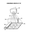
この画像取得装置の構成例を図52に示す。図52に示される画像取得装置は、撮像部201と、駆動部202と、支柱203と、制御部205と、インタフェース204と、支持台206と、2つの操作スイッチ207で構成される。
A configuration example of this image acquisition apparatus is shown in FIG. The image acquisition apparatus shown in FIG. 52 includes an
駆動部202は、撮像部201を点線で示されるように回転駆動させる。支柱203は、撮像部201と駆動部202を支持する。制御部205は、画像取得装置の制御を行うとともに、支持台206とともに支柱203を支える構造となっている。操作スイッチ207は、画像取得装置の操作をするためのものである。紙文書208のA〜Iの点線で示された部分領域は、画像取得装置が撮影する各部分領域を表している。
The driving
次に、上述した撮像部201、駆動部202、制御部205のさらに詳細な構成を図53に示す。
Next, further detailed configurations of the above-described
制御部205は、システムコントローラ211と、CPU(Central Processing Unit)210と、SDRAM(Synchronous Dynamic Random Access Memory)212と、PCI(Peripheral Component Interconnect)バス213と、PCMCIA(Personal Computer Memory Card International Association)214と、I/O(Input/Output)入出力デバイス215と、IDE217と、PCI/ISA(Industry Standard Architecture)ブリッジIDE(Integrated Drive Electronics)USB(Universal Serial Bus)変換インタフェース218と、USB219と、ハードディスク216と、ISAバス220と、I/Oコントローラ221と、シリアル222と、パラレル234と、LAN(Local Area Network)インタフェース235より構成される小型のボードコンピュータユニットである。
The
制御部205は、撮像部201の動作制御、撮像装置201から転送された画像の画像処理や編集、記録等を行い、外部機器へインタフェース204(図52参照)を介して接続され、外部機器との通信を行なう。
The
インタフェース204としては、PC用の汎用インタフェース、例えば、RS−232C、USB、IEEE1394、ネットワークアダプタ、IrDA(Infrared Data Association)を用いる。本実施例では、制御部205を用いる構成を示しているが、制御部205により行う処理や記録を、撮像部201内のMPU236で代用するような構成としても構わない。
As the
次に、駆動部202の説明をする。駆動部202は、ステッピングモータX255、ステッピングモータY256及び回転量検出用のロータリエンコーダX244、ロータリエンコーダY257と、検出回路258と、駆動回路243で構成される。
Next, the
なお、所定の回転位置で静止するような基準位置を設けてステッピングモータの回転位置をキャリブレーションすれば、各ロータリエンコーダと検出回路は設けなくてもよい。 Note that if a rotation position of the stepping motor is calibrated by providing a reference position that stops at a predetermined rotation position, the rotary encoders and the detection circuit may not be provided.
次に撮像部201を説明する。この撮像部201の説明は、撮像部201とともにレンズも図示されている図54を用いて説明する。
Next, the
図54には、CDS(Correlated Double Sampling:相関二重サンプリング)241と、A/D変換器242と、IPP(Image Pre-Processor)281と、メモリ240と、TG(Timing Generator)280と、MPU236と、I/Oコントローラ237と、I/Oデバイス261と、固定レンズ267、268と、ズームレンズ266と、絞り機構265と、シャッタ264と、フォーカスレンズ263と、撮像素子262で構成される。なお、I/Oデバイス261は、図53で説明したシリアル238とUSB239とを、まとめて表現したものである。
FIG. 54 shows a CDS (Correlated Double Sampling) 241, an A /
被写体の像は、固定レンズ267、268、ズームレンズ266、絞り機構265、フォーカスレンズ263を通して、シャッタ264により露光時間が制御され、撮像素子262上に形成される。撮像素子262からの画像信号はCDS241でサンプリングされた後、A/D変換器242でデジタル信号化される。この時のタイミングはTG280で生成される。画像信号はその後、IPP281でアパーチャ補正などの画像処理、圧縮などが行われ、メモリ240に保存される。
The image of the subject is formed on the
各ユニットの動作は、MPU236にて制御される。また、I/Oコントローラ237はI/Oデバイス261を介して、外部の機器と接続され、画像の入出力、撮影制御信号の通信等に用いられる。
The operation of each unit is controlled by the
次に、一枚の被写体を分割して撮影する場合の制御部205の動きについて、再び図53を用いて説明する。
(1)制御部205は、I/O入出力デバイス215より駆動部202の駆動回路243にパルス電圧を印加し、所定の角度になるように検出回路258の回転検出値をフィードバックする。
(2)制御部205は、USB219より撮像部201のUSB239へ撮影コントロール信号を送信する。
(3)必要に応じて(1)、(2)が繰り返される。画像転送が指示されるとUSB239を介して撮像装置201から画像が制御部205に転送され、その画像を制御部205は、LANインタフェース235を介してネットワークに送信する。
(4)紙文書208(図52参照)は、図55に示されるように、後述する2次元コード290等のデータ識別情報が印字されているものとする。この符号化紙IDである2次元コードは、要素Eによりデコードされ、デコードが成功し、紙IDが取得できたなら、デバイスタイプ、紙ID、画像等の情報は、XML形式のデータとして要素Kへ送信される。
Next, the movement of the
(1) The
(2) The
(3) (1) and (2) are repeated as necessary. When image transfer is instructed, the image is transferred from the
(4) It is assumed that the paper document 208 (see FIG. 52) is printed with data identification information such as a two-
次に、紙文書上の画像の撮影から、撮影により得られた画像へ2次元コードをデコードした結果を対応づけるまでの画像取得装置の処理を、図56のフローチャートを用いて説明する。 Next, processing of the image acquisition apparatus from shooting of an image on a paper document to associating a result of decoding a two-dimensional code with an image obtained by shooting will be described with reference to the flowchart of FIG.
ステップS1401で、画像取得装置は、ズームレンズを調整し、被写体と撮像面がほぼ正対した位置関係において、被写体となる紙文書の全体が写るように全体画像撮影を行う。ステップS1402で、画像取得装置は、撮影した画像より2次元コード等のコードの存在するコード領域を検出する。次に、画像取得装置は、ステップS1403で、コード領域の領域座標と重心位置を算出する。この場合、予めコードの存在する領域を規定しておくことで、ステップS1403の高速化を図るようにしても良い。或いは、領域はコード領域の外接矩形領域とし、外接矩形領域の重心位置を算出するようにしても良い。 In step S1401, the image acquisition apparatus adjusts the zoom lens, and captures the entire image so that the entire paper document that is the subject is captured in a positional relationship in which the subject and the imaging surface face each other. In step S1402, the image acquisition apparatus detects a code area in which a code such as a two-dimensional code exists from the captured image. Next, in step S1403, the image acquisition apparatus calculates the area coordinates and the barycentric position of the code area. In this case, the speed of step S1403 may be increased by prescribing the area where the code exists. Alternatively, the area may be a circumscribed rectangular area of the code area, and the barycentric position of the circumscribed rectangular area may be calculated.
ステップS1403で得られた領域座標とその重心位置の座標から、画像取得装置はステップS1404で、データを識別する情報をより大きい撮像画像として取得する為のズーム倍率と駆動部202の駆動量を線形演算により算出する。この駆動量は、光軸をロール軸としたパン(左右)、チルト(上下)の2方向から算出する。
From the region coordinates obtained in step S1403 and the coordinates of the barycentric position thereof, in step S1404, the image acquisition apparatus linearly sets the zoom magnification and the driving amount of the
算出された結果に基づき、画像取得装置は、ステップS1405で、駆動部202を駆動する。次のステップS1406で、画像取得装置は、駆動させた位置で撮影する。ステップS1407で、画像取得装置は、読み込んだコードを要素Eによりデコードする。そして、ステップS1408で、画像取得装置は、全体撮影画像に対してデコード結果を対応付ける。
Based on the calculated result, the image acquisition apparatus drives the
これによりコード領域のみを高解像で取得し、高速に取り込んだ全体画像に対して、信頼性の高い紙IDを付与できるようになる。 As a result, only the code area can be acquired with high resolution, and a highly reliable paper ID can be assigned to the entire image captured at high speed.
次に、実際の撮影について説明する。上述したように、画像取得装置は、撮像部を駆動することで、紙文書を分割撮影し、分割撮影した各画像を1つの画像に合成するようになっている。 Next, actual photographing will be described. As described above, the image acquisition device is configured to divide and shoot a paper document by driving the imaging unit, and to synthesize each of the divided and captured images into one image.
そこでまず分割撮影について説明する。既に説明した図52に示されるように、撮像部201が、点線で示された左右方向へ駆動をすることで、領域A、B、Cを撮影することができる。
First, split imaging will be described. As illustrated in FIG. 52 described above, the
さらに、撮像部201が、図57に示されるように、上下方向へ駆動することでA〜Iまでの全ての領域を撮影領域にすることができる。なお、図57は、撮像部201が紙文書208を撮影する様子を示すものであり、撮像部201は、紙文書208の2つの領域301、302を撮影している。
Furthermore, as shown in FIG. 57, the
上述したように、被写体を高解像に撮影する場合は、撮像系の画角をできるだけ狭くし、複数の位置で撮影する。この場合、被写体のすべての部分が分割画像のいずれかに撮影されるように撮影を行う。 As described above, when shooting a subject with high resolution, the angle of view of the imaging system is made as narrow as possible and shot at a plurality of positions. In this case, shooting is performed so that all parts of the subject are shot in one of the divided images.
このようにして撮影された分割画像と、分割画像を接合することで合成した合成画像を図58と図59を用いて説明する。分割画像は、図58に示されるように、アルファベットが描かれた画像が6分割されたものである。この図58に示されるように、図の下方向の文字ほど、小さくなっていることが分かる。これら6つの分割画像を、接合した画像が、図59に示される画像である。 A divided image shot in this way and a synthesized image synthesized by joining the divided images will be described with reference to FIGS. 58 and 59. FIG. As shown in FIG. 58, the divided image is obtained by dividing an image on which an alphabet is drawn into six parts. As shown in FIG. 58, it can be seen that the characters in the downward direction in the figure are smaller. An image obtained by joining these six divided images is an image shown in FIG.
このような方法で画像を接合する場合に限らず、分割せずに1枚で被写体を撮影する場合でも、図59のような台形上の歪(あおり歪)が生じる。従って、図60に示されるような、正対した画像にする必要がある。図60に示される画像は、図59の画像に、あおり歪の補正、ノイズ除去を行った画像である。 Not only when images are joined by such a method, but also when a subject is photographed without being divided, trapezoidal distortion (tilt distortion) as shown in FIG. 59 occurs. Therefore, it is necessary to make the image face up as shown in FIG. The image shown in FIG. 60 is an image obtained by correcting tilt distortion and removing noise from the image of FIG.
このようなあおり歪の補正は、被写体に正対した位置での正対画像を基準とし、正対画像と他の画像との間の射影変換行列を予め求め、それを用いて画像を再配置することにより得られる。 The correction of tilt distortion is based on the directly-facing image at the position facing the subject, and a projection transformation matrix between the facing image and another image is obtained in advance, and the image is rearranged using it. Can be obtained.
この撮影の説明を簡単にするため、図57に示した2つの領域301、302を分割撮影する場合について説明する。まず、領域301上の点と領域302上の点をそれぞれ、数1が示す2点とする。
In order to simplify the description of this shooting, a case will be described in which the two

数1、数2、数3を用いることにより、領域302上の各点が領域301上の位置で撮影された場合の位置を算出することができるため、領域301上を基準とし、領域301上に領域302上の画素をマッピングすることができる。分割画像が3枚以上の場合も、例えば1つの領域と他の領域との射影変換行列を予め算出しておく。そうすることで、正対された分割画像が得られ、順次接合していくことで、図60に示した正対された画像を得ることができる。
By using
以上が画像取得装置の構成や処理内容である。次に、この画像取得装置の6つの変形例について説明する。なお、以下の説明において、図52で説明した符号など、既に説明した符号についての説明は省略する。 The above is the configuration and processing content of the image acquisition apparatus. Next, six modified examples of the image acquisition device will be described. In the following description, the description of the already described symbols such as the symbols described in FIG. 52 is omitted.
第1の変形例である図61に示される画像取得装置は、図52に示した画像取得装置に、2次元コード等のコードを読み取る為の撮像部310を、紙文書を取り込む為の撮像装置201とは別に設けたものである。
The image acquisition apparatus shown in FIG. 61, which is a first modification, includes an
この図61に示した画像取得装置は、コードの存在する小領域を高解像で取り込む目的で設けた為、撮像部201よりも小型で安価な画像入力装置で構成すれば良い。また、この場合の画像取得装置は、撮像部201により取り込んだ画像に対応させて、撮像部310により取り込んだ画像上のコード311のデコード結果を記録するものとする。
The image acquisition apparatus shown in FIG. 61 is provided for the purpose of capturing a small area where a code exists with high resolution, and therefore may be configured with an image input apparatus that is smaller and less expensive than the
次の図62に示される第2の変形例は、撮像部310の代わりに紙ID情報読み取り部312を設けたものである。この紙ID情報読み取り部312は、汎用のバーコードリーダ等で使用されている撮像ユニットを用いることを想定している。
The second modified example shown in FIG. 62 includes a paper ID
次に、図63を用いて、第3の変形例について説明する。図63に示される画像取得装置は、入力する紙文書208の下敷き313上にコード311を設けた装置構成であり、支柱203は、支持台315に支持される。これによりコードの付与されていない紙に対してコードを付与できるようにできるとともに、プリンタなどと組み合わせ、再度、紙に出力することで、コードを付与することも可能である。
Next, a third modification will be described with reference to FIG. The image acquisition apparatus shown in FIG. 63 has an apparatus configuration in which a
次の図64に示される第4の変形例は、支持台315に収納可能な平面部材上にコード314を設けた装置構成となっている。
The fourth modified example shown in FIG. 64 has a device configuration in which a
また、図65に示される第5の変形例は、撮像部201上に投影部316を設けることで、点線で示された投影領域317にコード316を投影できる装置構成とする。そして、ユーザが自由に投影するコードを電子データとして編集可能なものとする。
The fifth modified example shown in FIG. 65 has an apparatus configuration in which the
この投影部316は、図65において撮像部201上に設けられているが、別な部位に固定するものであっても構わない。また、投影部316は光源、集光レンズ、ミラー、液晶パネル、投射レンズから構成される代表的な液晶プロジェクタと同様の構成のものやDMD(Digital Mirror Device)を用いたDLP(Digital Light Processing)による構成等いずれの構成のものでも良いが、小型なものとしたほうがよい。
The
図66に示される第6の変形例は、点線で示された撮像範囲に液晶ディスプレイ等の表示デバイスを有する携帯情報端末318を設け、この表示デバイス上にコードを表示させることで、取り込む紙文書208に対応させたコードを付与できるようにする。
A sixth modification shown in FIG. 66 is a paper document to be captured by providing a
以上が6つの変形例であるが、図63〜図66において駆動部を図示していないのは、駆動部を有する構成に限定されないことを示している。 The above are the six modified examples, but the fact that the drive unit is not shown in FIGS. 63 to 66 indicates that the configuration is not limited to the configuration having the drive unit.
次に、要素Dの他の実施例である筆記情報入力装置60を図13に示す。筆記情報入力装置60は、紙への筆記情報を取得するデジタイザなどの座標入力装置74と、紙に印刷されている情報と電子的な情報とを対応付け識別するための紙ID情報読取装置75と、電子的な紙IDの発行を指示する紙ID発行ボタン401と、紙IDを新規に発酵する紙ID発行装置400と、取得した情報を保持する記憶装置71と、取得・保持された情報をPCに送信する通信装置72と、これらの装置を制御する制御装置73とを有する。
Next, a writing
座標入力装置74は、手書き座標を連続的に取得するデジタイザなどを用いることができる。デジタイザを用いた場合、その方式には公知のものとして電磁誘導方式、超音波距離計の原理を用いた三角測量方式などのものがあるが、いずれもセンサと専用入力ペンによって紙に行われた筆記動作を検出し、筆記情報、この場合は筆記された軌跡の座標である筆記座標を計測する装置である。このようにして計測された筆記座標の集合が筆記情報となる。
As the coordinate
専用入力ペンのペン先には実際に紙に筆記することの可能なペン先が備わり、電子的に筆記座標を検出すると同時に紙に筆記軌跡を記入できるように構成することが望ましい。 It is desirable that the pen tip of the dedicated input pen is provided with a pen tip that can actually be written on paper so that the writing locus can be written on the paper simultaneously with electronic detection of the writing coordinates.
紙ID情報読取装置75は例えばプリンタによって紙に印刷された符号化紙IDを読み取り、解読する装置であり、公知のものとして2次元コードリーダ、1次元バーコードリーダなどを用いる。ここで、紙ID情報読取装置に2次元コードリーダを用いた場合には、たとえばコード化に公知のQRコード(登録商標)を用いた場合には、英数字で最大4296文字の情報を識別することが可能であり、一般に利用者が印刷した書類を識別するためには十分な容量を得ることができる。
The paper ID
紙ID発行ボタン401は、新規の紙IDの発行を指示するときに用いられるボタンである。紙ID発行ボタン401の押下によって新規の紙IDの発行指示が紙ID発行装置400に与えられ、紙ID発行装置400によって新規の紙IDが発行される。紙ID発行装置400によって新規に発行された紙ID(以下、装置発行紙IDという)は、文書処理システムによって発行され、紙面に印刷され、紙ID情報読取装置75によって読み取られた紙IDと同様に、筆記座標情報と共に記憶装置71に保存、処理される。
A paper
紙ID発行装置400は、新規に装置発行紙IDを生成、発行する装置である。上述したように装置発行紙IDは、文書処理システムによって発行される紙IDと同様に処理される。ここで、紙ID発行装置400は、制御装置73上のソフトウェアとして筆記情報入力装置60に実装することも可能である。
The paper
記憶装置71はハードディスクや、不揮発性メモリであり、コンパクトフラッシュ(登録商標)ディスクなどの取り外し可能なメモリなどを用いることもでき、上記紙ID情報読取装置75によって取得された筆記座標、印刷条件情報、電子文書情報を保存する。このとき、PCとのデータのやり取りは、メモリを直接に接続することで可能となり、通信装置72を省くこともできる。
通信装置72は、蓄えられた情報を送信する装置であり、イーサネット(登録商標)、無線LANなどのネットワーク技術や、USBやブルートゥース、シリアル接続技術などが用いられる。
The
The
制御装置73は、例えばマイクロコンピュータによって構成され、上記の装置を後述する動作にしたがって動作制御する。
The
これらの装置は一体に構成することも可能であるし、個々の装置に分かれて構成することも可能である。また、一体型に構成した場合、バッテリ駆動とすることで、さまざまな場所に移動して利用することが可能になる。印刷した紙への筆記作業は、オフィスの机の上だけとは限らないため、筆記情報入力装置を一体かつ可搬型に構成することが望ましい。 These devices can be configured integrally, or can be configured separately for each device. Moreover, when it is configured as an integral type, it can be moved to various places and used by being driven by a battery. Since the writing work on the printed paper is not limited to being performed on an office desk, it is desirable that the writing information input device is configured to be integrated and portable.
一体型に成形した筆記情報入力装置60の外観例を図14に示す。図示した例では、紙ID情報読取装置75(図13参照)を2次元コードリーダ62として実現しており、また設置された紙文書には印刷された文書本文65と、紙ID63が、予め印刷されている。座標入力装置74は超音波式のデジタイザによって実現しており、専用入力ペン66によって実際に筆記情報64を加えると共に、座標データを取得することが可能になっている。
FIG. 14 shows an example of the appearance of the writing
次に、可搬型のデジタイザ型の筆記情報入力装置60を用いた場合の処理について図15を用いて説明する。まず、ステップS601において、座標入力装置74は、専用入力ペン66のペン先が紙文書と接触(ペンダウン)したか否かを判定する。座標入力装置74は、ペンダウンしたと判定すると(ステップS601においてYES)、ステップS602に進み、ペンダウンしていないと判定すると(ステップS601においてNO)、ステップS601の処理を繰り返す。
Next, processing when the portable digitizer type writing
ステップS602では、座標入力装置74が、デジタイザと同様の技術を用いて、筆記情報として座標を計測する。
In step S602, the coordinate
一方、ステップS603では、紙ID情報読取装置75が、2次元コードにエンコードされた紙ID63を読み取る処理を実行する。なお、紙ID情報読取装置75が、エンコードされた紙ID63を読み取るのは、座標入力装置74が、筆記情報として座標を読み取っている間、或いは座標入力装置74が、ペンダウンを検出したときなど適宜行われる。
On the other hand, in step S603, the paper ID
次にステップS604で、紙ID情報読取装置75は、エンコードされた紙ID63をデコード(解読)可能か否かを判定する。紙ID情報読取装置75は、エンコードされた紙ID63をデコード可能であると判定すると(ステップS604においてYES)、出コードを実行し、ステップS605に進み、何らかの理由でステップS603の処理が失敗し、エンコードされた紙ID63が読み取れなかったり、読み取ったエンコードされた紙ID63のデコードが不可能であったりすると判定すると(ステップS604においてNO)、ステップS608に進む。
In step S604, the paper ID
ステップS604からステップS605に進むと、例えば制御装置73は、ステップS603において紙ID情報読取装置75が読み取り、ステップS604においてデコードした紙IDと、ステップS602において座標入力装置74が読み取った筆記情報とを、対応付けて、一旦、記憶装置71に保存する。
When the process proceeds from step S604 to step S605, for example, the
ステップS605からステップS606に進み、例えば制御装置73は、筆記情報等の取得処理を終了するか否かを判定する。制御装置73が、筆記情報等の取得処理を終了すると判定すると(ステップS606においてYES)、ステップS607に進み、筆記情報等の取得処理を終了しないと判定すると(ステップS606においてNO)、ステップS601からの処理を繰り返す。
Proceeding from step S605 to step S606, for example, the
ステップS606からステップS607に進み、例えば制御装置73は、ステップS605において記憶装置71に保存した紙IDや筆記情報等を、通信装置72を介してPCへ送信する。
Proceeding from step S606 to step S607, for example, the
一方、ステップS604からステップS608に進むと、例えば制御装置73は、装置発行紙IDが既に発行されているか否かを判定する。制御装置73は、装置発行IDが既に発行されていると判定すると(ステップS608においてYES)、ステップS609に進み、装置発行IDがまだ発行されていないと判定すると(ステップS608においてNO)、ステップS610に進む。
On the other hand, when the process proceeds from step S604 to step S608, for example, the
例えば制御装置73は、記憶装置71に記憶されている後述する図16及び図17に示されるようなテーブルを参照し、既に装置発行IDが発行されているか否かを判定する。
For example, the
ステップS608からステップS609に進むと、例えば制御装置73は、記憶装置71より既に発行されている装置発行IDを読み出し、ステップS605に進む。
When the process proceeds from step S608 to step S609, for example, the
ステップS609からステップS605に進んだ場合、例えば制御装置73は、ステップS609で読み出した装置発行紙IDと、ステップS602において座標入力装置74が読み取った筆記情報とを、対応付けて、一旦、記憶装置71に保存する。ステップS606以降の処理は、上述したのと同様である。
When the process proceeds from step S609 to step S605, for example, the
一方、ステップS608からステップS610に進むと、例えば制御装置73等からの要求に応じて、紙ID発行装置400が、装置発行紙IDを発行する。
On the other hand, when the process proceeds from step S608 to step S610, the paper
ステップS610からステップS605に進んだ場合、例えば制御装置73は、ステップS610において紙ID発行装置400が発行した装置発行紙IDと、ステップS602において座標入力装置74が読み取った筆記情報とを、対応付けて、一旦、記憶装置71に保存する。ステップS606以降の処理は、上述したのと同様である。
When the process proceeds from step S610 to step S605, for example, the
なお、紙ID発行ボタン401等がユーザによって押下された場合は、割り込み処理が実行され、ステップS610で示したように、紙ID発行装置400が、装置発行紙IDを発行し、後述する図16や図17に示されるようなテーブルの、対応する紙ID番号の場所に、装置発行紙IDが格納される。
When the paper
ここで、記憶装置に保存され、PCに送信される情報の例を、図16及び図17を用いて示す。図16は、記憶装置に保存されている情報の例(その1)である。 Here, examples of information stored in the storage device and transmitted to the PC will be described with reference to FIGS. 16 and 17. FIG. 16 is an example (part 1) of information stored in the storage device.
記憶装置71は、例えば図16に示されるようなテーブルを保持する。該テーブルは、図16に示されるように、装置識別番号と、紙ID番号と、筆記X座標と、筆記Y座標と、ペンU/Dとを項目として含む。なお、図16では、装置発行紙IDが発行されなかった場合の、テーブルの例が示されている。
The
図16に示される装置識別番号には、筆記情報入力装置60を識別する識別番号が格納されている。また、図16に示される紙ID番号には、筆記情報入力装置60が読み取った紙の紙IDが格納されている。また、図16に示される筆記X座標には、筆記情報入力装置60が読み取った筆記座標情報のX座標が格納されている。また、図16に示される筆記Y座標には、筆記情報入力装置60が読み取った筆記座標情報のY座標が格納されている。また、図16に示されるペンU/Dには、専用入力ペンのアップ/ダウンを識別する識別子(図の例ではU又はD)が格納されている。
In the apparatus identification number shown in FIG. 16, an identification number for identifying the writing
図17は、記憶装置に保存されている情報の例(その2)である。なお、図17では、装置発行紙IDが発行された場合の、テーブルの例が示されている。 FIG. 17 is an example (part 2) of information stored in the storage device. Note that FIG. 17 shows an example of a table when an apparatus issue paper ID is issued.
図17に示される紙ID番号には、筆記情報入力装置60が読み取った紙の紙ID又は筆記情報入力装置60が発行した装置発行紙IDが格納されている。
The paper ID number shown in FIG. 17 stores the paper ID of the paper read by the writing
例えば、図17の紙ID番号の1行目は、0001と、筆記情報入力装置60が読み取った紙の紙IDが格納されている。また、図17の紙ID番号の2行目から9行目には、筆記情報入力装置60が発行した装置発行紙ID(P0001)が格納されている。
For example, the first line of the paper ID number in FIG. 17
このように、装置発行紙IDは、アルファベットと数字の組み合わせとなっており、読み取った紙IDと、発行した装置発行紙IDとは、明らかに識別可能なものとなっている。 As described above, the device issuance paper ID is a combination of alphabets and numbers, and the read paper ID and the issued device issuance paper ID are clearly identifiable.
また、図17の紙ID番号の10行目と11行目とには、筆記情報入力装置60が発行した、2行目から9行目とは異なる装置発行紙IDが格納されている。これは例えば、2次元コードにエンコードされた紙ID63を読み取ることが出来ず、筆記情報入力装置60の紙ID発行装置400が既に装置紙発行IDを発行している状態で、紙ID発行ボタン401がユーザによって押下され、新たな装置紙発行IDが発行されたことを示している。例えば2次元コードにエンコードされた紙ID63を読み取ることが出来ない、読み取り不能用紙を複数枚利用する場合、ユーザは、新しい読み取り不能用紙を筆記情報入力装置60にセットした際に、紙ID発行ボタン401を押下し、新しい装置紙発行IDの発行を指示する。
In addition, the 10th and 11th lines of the paper ID number in FIG. 17 store apparatus issue paper IDs issued by the writing
なお、図13に示したように、筆記情報入力装置60は、座標入力装置74と、紙ID情報読取装置75とを備えており、これらは別個に読取り動作が可能であるため、紙から紙IDを読み取ることが出来なくても、筆記情報は取得することができる。
As shown in FIG. 13, the writing
図13から図17に示したような構成、処理によって、紙IDを読み取れなかった場合に取得された筆記情報に対して適切な紙IDを発行し、取得された加筆情報(又は加筆座標)を有効に活用することができる。 An appropriate paper ID is issued for the writing information acquired when the paper ID cannot be read by the configuration and processing shown in FIGS. 13 to 17, and the acquired writing information (or writing coordinates) is obtained. It can be used effectively.
次に、要素Dの他の実施例について説明する。この実施例は、記入が終わった紙文書から、スキャナなどを用いて紙文書の電子画像を取得し、要素Eへデータを渡す実施例である。 Next, another embodiment of the element D will be described. In this embodiment, an electronic image of a paper document is acquired from a paper document that has been filled in using a scanner or the like, and data is transferred to the element E.
最初に、図18を用いて画像入力装置について説明する。画像入力装置88は、画像入力装置88内の各装置を制御するための制御装置82と、プログラムや画像を記憶するための記憶装置83と、外部接続されたスキャナ80やMFP86と通信してそれらを制御するためのスキャナ制御装置81と、画像を処理するための画像処理装置84と、外部ネットワークとの通信を制御するネットワーク制御装置85とを有する。
First, the image input apparatus will be described with reference to FIG. The
この画像入力装置88には、直接接続されたスキャナ80や、ネットワーク87を介して通信可能なMFP86を利用して画像を入力することができる。
An image can be input to the
この画像入力装置の処理を、図19のフローチャートを用いて説明する。図19に示されるフローチャートは、画像入力装置を使って座標を取得し、要素Kへデータを渡す処理を示している。 The processing of this image input apparatus will be described using the flowchart of FIG. The flowchart shown in FIG. 19 shows a process of acquiring coordinates using an image input device and passing data to an element K.
ステップS701は、画像の読み取りである。これは、ユーザが記入を終えた文書をスキャナ80またはMFP86を用いて画像の読み取りを行う処理である。この場合の読み取り条件は、例えば600dpi、白黒2値画像である。画像の2値化は通常のスキャナが有している2値化機能を使用する。
Step S701 is image reading. This is a process of reading an image of a document that the user has completed using the
読み取られた紙文書の画像は、ステップS702で、記憶装置83の所定のフォルダに画像ファイルとして蓄えられ、次処理へのキューに入る。この読み取った画像を所定のフォルダに画像ファイルとして蓄えるように制御するのはスキャナ制御装置81の役割であり、スキャナ80やMFP86のボタンが押され、画像がそれらから転送されることを検知し、転送された画像を記憶装置83の所定のフォルダに格納する。
In step S702, the read image of the paper document is stored as an image file in a predetermined folder of the
画像処理装置84は、スキャナ80やMFP86から入力される画像が保存される記憶装置83のフォルダを監視し、キューの先頭にある画像から順番に、ステップS703で画像正立処理を行い、ステップS704で領域抽出処理を行い、ステップS705でデコード処理を行う。ステップS706で、デコードができたかどうか判断し、デコードできた場合は、紙IDの取得を行い、処理を終了する。また、デコードできなかった場合も処理を終了する。
The
この図19に示したフローチャートは、情報取得段階の処理を示すものである。また、このようにして取得された紙IDは、後述する管理テーブルにより、文書ID及び処理IDに変換することができる。 The flowchart shown in FIG. 19 shows processing in the information acquisition stage. Further, the paper ID acquired in this way can be converted into a document ID and a processing ID by a management table described later.
なお、ステップS702の処理で、キュー方式を使用するのは、ADF(Auto Document Feeder)等を使用して多数の画像が入力されたとき、同時に複数の画像が処理されると画像処理装置84の負荷が非常に高くなり動作が不安定になりかねないことと、処理の速度が遅くなることが理由として挙げられる。 Note that the cue method is used in the process of step S702 when a large number of images are input using an ADF (Auto Document Feeder) or the like and a plurality of images are processed at the same time. The reason is that the load becomes very high and the operation may become unstable, and the processing speed becomes slow.
また、ステップS703の画像正立処理は、次のステップ704の領域抽出処理が正立された画像から領域を抽出するようになっているため、スキャナから読み取られた方向の分らない画像を正立する処理である。
In the image erecting process in step S703, since the area is extracted from the image in which the area extracting process in the
この画像正立処理の詳細について図20のフローチャートを用いて説明する。まず、ステップS801では、読み取った画像についてOCR処理が行われ、その結果が保存される。次のステップS802、ステップS803、ステップS801のループでは、画像を90度ずつ回転させてOCR処理が行われ、それらの結果も保存される。 Details of the image erecting process will be described with reference to the flowchart of FIG. First, in step S801, OCR processing is performed on the read image, and the result is stored. In the next loop of step S802, step S803, and step S801, the image is rotated by 90 degrees to perform OCR processing, and the results are also saved.
90度ずつ回転させた4方向でOCR処理がなされると、ステップS804で、OCR処理結果の尺度のひとつである確信度を用いて画像の方向が判定される。この確信度とは認識した文字の確からしさであり、この画像方向判定に使用する確信度は、各文字の確信度の平均である。この平均の確信度がもっとも大きい値を持つ方向での画像が正立であると判定する。 When the OCR process is performed in the four directions rotated by 90 degrees, in step S804, the image direction is determined using the certainty factor which is one of the scales of the OCR process result. The certainty factor is the certainty of the recognized character, and the certainty factor used for the image direction determination is an average of the certainty factor of each character. It is determined that the image in the direction having the largest average certainty factor is upright.
このようにして画像正立処理を終えると、図19のステップS704の処理である紙IDを有する2次元コードの検出・デコードするための領域抽出処理が行われる。領域抽出処理は、画像中の白画素で囲まれた黒画素を含む領域を検出する。この領域抽出の詳細を図21のフローチャートを用いて説明する。 When the image erecting process is completed in this manner, an area extraction process for detecting and decoding a two-dimensional code having a paper ID, which is the process in step S704 of FIG. 19, is performed. In the area extraction process, an area including black pixels surrounded by white pixels in the image is detected. Details of this region extraction will be described with reference to the flowchart of FIG.
まず、ステップS901の連結黒画素のラベル付け処理では、画像を左上の原点から走査する。そして、左上、上、左の画素が白画素であり、現在着目している画素が黒画素である場合に、その黒画素に新たなラベルをつける。それ以外の画素の場合は左上、上、左のいずれかにある黒画素のラベルを画素につける。 First, in the connected black pixel labeling process in step S901, the image is scanned from the upper left origin. When the upper left, upper, and left pixels are white pixels, and the currently focused pixel is a black pixel, a new label is attached to the black pixel. In the case of other pixels, the pixel is labeled with a black pixel on any of the upper left, upper, or left.
具体的に、図22を用いて説明する。まず、図22に示される数字が書かれた四角形は、全て黒画素であるとする。これを踏まえ、上記処理を図22の画素90、91、92、93を用いて説明する。このとき走査される順番は、画素90、91、92、93の順である。
This will be specifically described with reference to FIG. First, it is assumed that all the squares with numbers shown in FIG. 22 are black pixels. Based on this, the above processing will be described using the
まず、画素90について着目すると、画素90の左上、上、左の画素が白画素であり、現在着目している画素90が黒画素であるため、ラベル「1」が画素90につけられる。
First, when attention is paid to the
次に走査される画素91について着目すると、左上、上の画素は白画素であるが、左が白画素ではないため、左上、上、左のいずれかにある黒画素のラベルが画素91につけられる。従って、画素91には画素90と同じラベル「1」がつけられる。
Focusing on the
次に、画素92について着目すると、画素92の左上、上、左の画素が白画素であり、現在着目している画素92が黒画素であるため、新たなラベル「2」が画素92につけられる。
Next, focusing on the
次に走査される画素93について着目すると、左上、上の画素は白画素であるが、左が白画素ではないため、左上、上、左のいずれかにある黒画素のラベルが、現在着目している画素93につけられる。従って、画素93には画素92と同じラベル「2」がつけられる。
Focusing on the
このようにして、以下の画素についても、同様の処理が行われる。 In this way, the same processing is performed for the following pixels.
次のステップS902で行なわれる連結黒画素の外接矩形座標検出処理では、同一のラベルを有する黒画素群を囲む外接矩形座標を検出する。そのことを示す図が、図23である。図23に示されるように、ラベル「1」の黒画素群の外接矩形94と、ラベル「2」の黒画素群の外接矩形95が検出される。
In the circumscribed rectangular coordinate detection process of the connected black pixels performed in the next step S902, circumscribed rectangular coordinates surrounding the black pixel group having the same label are detected. FIG. 23 shows this. As shown in FIG. 23, a circumscribed
次のステップS903は、重なり、接触のある外接矩形を統合する処理で、各外接矩形に重なり或いは接触がある外接矩形同士を統合し、新たな外接矩形が形成される処理である。それが図24の外接矩形96である。
The next step S903 is a process of integrating circumscribed rectangles that overlap and touch, and is a process of integrating circumscribed rectangles that overlap or touch each circumscribed rectangle to form a new circumscribed rectangle. This is the circumscribed
そして、ステップS904で、2次元コードの大きさとしてありえない大きさの外接矩形を排除するため、所定の範囲の大きさの外接矩形が抽出される。以上により、白に囲まれた黒画素を含む領域が検出されたので、検出された矩形領域全てに対して画像処理装置84でデコードを行うことができる。
In step S904, a circumscribed rectangle having a size within a predetermined range is extracted in order to exclude a circumscribed rectangle having a size that is impossible as the size of the two-dimensional code. As described above, since an area including black pixels surrounded by white is detected, the
予め、2次元コードの位置がわかっているならば所定の位置にある矩形領域のみにデコードを行えばよいが、紙文書のレイアウトによってどこに2次元コードが存在するかわからない場合は、検出した矩形領域すべてに対してデコードを行い、デコードできたものを紙IDとして検出するようにする。なお、デコードの詳細は、次の要素Eの説明で行う。 If the position of the two-dimensional code is known in advance, the decoding may be performed only on the rectangular area at the predetermined position. If the position of the two-dimensional code is not known depending on the layout of the paper document, the detected rectangular area Decoding is performed for all, and the decoded one is detected as a paper ID. The details of decoding will be described in the explanation of the next element E.
デコードが成功し、紙IDの取得ができたなら、デバイスタイプ、紙ID、筆記情報が要素Kへ送信される。この場合、上記情報は、XML(eXtensible Markup Language)形式のデータとして要素Kへ送信される。 If the decoding is successful and the paper ID is obtained, the device type, paper ID, and writing information are transmitted to the element K. In this case, the information is transmitted to the element K as data in XML (eXtensible Markup Language) format.
また、ここで使用したスキャナはフラットベッドスキャナ以外にも、デジタルカメラ、書画カメラ等の画像撮像装置も使用できる。 In addition to the flatbed scanner, the image pickup apparatus such as a digital camera or a document camera can be used as the scanner used here.
次に、紙IDをデコードする要素Eについて説明する。まず、要素Eの説明として、2次元コードを読み取るバーコード読取装置について説明する。バーコード読取装置は、図25に示されるように、頂点候補検出部11と、コード枠検出部12と、射影変換係数算出部13と、データサンプリング部14と、誤り訂正部15と、フォーマット変換部16とを有する。また、バーコード読取装置は、上述した図14の2次元コードリーダ62に示されるように、斜め上から2次元コードを読み取るようになっている。
Next, the element E that decodes the paper ID will be described. First, as an explanation of the element E, a barcode reader that reads a two-dimensional code will be described. As shown in FIG. 25, the barcode reader includes a vertex
頂点候補検出部11は、2次元コードの頂点候補を検出する。コード枠検出部12は、頂点候補に基づき、後述するコード枠を検出する。コード枠が検出されることで、頂点候補は真の頂点と確定される。
The vertex
射影変換係数算出部13は、コード枠検出部12で検出されたコード枠の各頂点の座標と、2次元コードを作成した時のコード枠の各頂点の規定座標とから、作成した2次元コードの各セルの規定中心座標と読み取った2次元コードの各セルの中心とをマッピングする係数である射影変換係数を求める。
The projective transformation
データサンプリング部14は、射影変換係数算出部13で求めた射影変換係数を用いて、2次元コードのデータのサンプリングを行う。誤り訂正部15は、データサンプリング部14が読み取ったデータが誤りかどうか判定し、誤りがないか、或いは誤り訂正が可能ならば、誤り訂正符号以外の整数型56ビットのデータをフォーマット変換部16へ出力する。フォーマット変換部16ではデータを数字文字列に変換して出力する。
The
次に、頂点候補検出部11の処理の詳細について説明する。図26は、入力画像の頂点候補を検出する処理を示す図である。図26に示されるように、頂点の検出は、矢印に示される方向に入力画像を走査することで検出するようになっている。具体的には、入力画像の四隅から斜め走査を行い、黒画素を検出し、検出された黒画素をA、B、C、Dとする処理が行われる。
Next, details of processing of the vertex
次に、図27を用いてA、B、C、Dが頂点候補かどうかを検出する処理について説明する。図27は、2次元コードを拡大した図である。この2次元コードに対し、頂点候補検出部11は、A、B、C、Dから矢印の方向、例えばAなら右下45度、Bなら左下45度というように、セルの一辺の画素数の1/√2の画素数だけ画素を追跡してそれらがすべて黒画素かどうかを判定する。それらがすべて黒画素であれば、頂点候補検出部11は、A、B、C、Dを頂点候補として検出し、コード枠検出部12に処理を移す。
Next, processing for detecting whether A, B, C, and D are vertex candidates will be described with reference to FIG. FIG. 27 is an enlarged view of the two-dimensional code. For this two-dimensional code, the vertex
次に、コード枠検出部12について説明する。コード枠検出部12では、図28のように、頂点候補A、B、C、Dから1/√2の画素数だけ追跡した終端どうしを結ぶ黒枠判定ライン76、77、78、79を通過する画素の黒画素の割合が全ての直線において直線毎に8割以上存在すればそれをコード枠であると判定し、頂点候補A、B、C、Dを2次元コードの頂点A、B、C、Dとして確定する。このとき、同時に頂点A、B、C、Dの座標も検出される。
Next, the code
次に、射影変換係数算出部13について説明する。射影変換係数算出部13では、コード枠検出部12で検出されたコード枠の各頂点の座標と、2次元コードを作成した時のコード枠の各頂点の規定座標とから、作成した2次元コードの各セルの規定中心座標と読み取った2次元コードの各セルの中心とをマッピングする係数である射影変換係数を求める。この射影変換係数の求め方は後に説明する。
Next, the projective transformation
次に、データサンプリング部14について説明する。データサンプリング部14には、2次元コード、2次元コードを作成した時点の各セルの規定中心座標、射影変換係数が入力される。データサンプリング部14は、射影変換係数算出部13で求めた射影変換係数を用いて、作成した2次元コードの各セルの規定中心座標を射影変換することにより、読み取った2次元コードの各セルの中心座標を求める。
Next, the
データサンプリング部14は、求めた中心座標を画像のサンプリング中心座標とし、その座標を中心とする3x3画素の黒画素数が白画素数を上回れば ‘1’、そうでなければ‘0’としてデータを読み出す。読み出された72ビットのデータは誤り訂正部15に入力、配列され、誤り訂正の判定が行われる。誤りがないか、或いは誤り訂正が可能ならば、誤り訂正部15は、誤り訂正符号以外の整数型56ビットのデータをフォーマット変換部16へ出力する。フォーマット変換部16ではデータを数字文字列に変換して出力することで、数字文字列が復元される。
The
上述した2次元コードの読取もソフトウェアでおこなってもよく、図29にその処理のフローチャートを示す。ステップS1001で斜め上から2次元コードを撮像した2次元コードが入力される。ステップS1002では、2次元コードの頂点候補が検出される。 The above-described reading of the two-dimensional code may be performed by software. FIG. 29 shows a flowchart of the processing. In step S1001, a two-dimensional code obtained by imaging the two-dimensional code is input from obliquely above. In step S1002, a vertex candidate of the two-dimensional code is detected.
このステップS1002では、図26に示すように画像の四隅から斜め走査が行われ、黒画素が検出される。検出された黒画素をA、B、C、Dとする。さらにステップS1002では、図27に示されるように、A、B、C、Dから矢印の方向、例えばAなら右下45度、Bなら左下45度というように、セルの一辺の画素数の1/√2の画素数だけ画素が追跡され、それらすべて黒画素かどうかが判定される。それらがすべて黒画素であればA、B、C、Dが頂点候補として検出され、ステップS1003に処理が移る。 In step S1002, diagonal scanning is performed from the four corners of the image as shown in FIG. 26, and black pixels are detected. Let the detected black pixels be A, B, C, and D. Further, in step S1002, as shown in FIG. 27, the direction of the arrow from A, B, C, D, for example, 45 degrees on the lower right for A and 45 degrees on the lower left for B, the number of pixels on one side of the cell is 1 Pixels are tracked by the number of pixels of / √2, and it is determined whether or not they are all black pixels. If they are all black pixels, A, B, C, and D are detected as vertex candidates, and the process proceeds to step S1003.
ステップS1003では、図28に示されるように、頂点候補A、B、C、Dから追跡した終端どうしを結ぶ黒枠判定ライン52、53、54、55を通過する画素の黒画素の割合が、全ての直線において直線毎に8割以上存在すればそれをコード枠であると判定される。そして、頂点候補A、B、C、Dが2次元コードの頂点A、B、C、Dとして確定される。このとき、同時に頂点A、B、C、Dの座標も検出される。 In step S1003, as shown in FIG. 28, all the black pixel ratios of pixels passing through the black frame determination lines 52, 53, 54, and 55 connecting the end points tracked from the vertex candidates A, B, C, and D If there is 80% or more of each straight line, it is determined as a code frame. Then, the vertex candidates A, B, C, and D are determined as the vertices A, B, C, and D of the two-dimensional code. At this time, the coordinates of the vertices A, B, C, and D are also detected.
このステップS1003で、コード枠が検出できなければ、ステップS1004の分岐処理でエンドに分岐し、読み取りは終了する。コード枠が検出された場合は、次のステップS1005へ処理は進む。 If the code frame cannot be detected in step S1003, the process branches to the end in the branch process of step S1004, and the reading ends. If a code frame is detected, the process proceeds to the next step S1005.
ステップS1005では、ステップS1003で検出されたコード枠の各頂点の座標と、2次元コードを作成した時のコード枠の各頂点の規定座標とから、作成した2次元コードの各セルの規定中心座標と読み取った2次元コードの各セルの中心とをマッピングする係数である射影変換係数が算出される。 In step S1005, the specified center coordinates of each cell of the created two-dimensional code from the coordinates of each vertex of the code frame detected in step S1003 and the specified coordinates of each vertex of the code frame when the two-dimensional code is created. Then, a projective transformation coefficient that is a coefficient for mapping the center of each cell of the read two-dimensional code is calculated.
次のステップS1006では、データサンプリングが行われる。具体的には、2次元コード、射影変換係数、作成した2次元コードの各セルの規定中心座標が入力され、ステップS1005で求まった射影変換係数を用いて、作成した2次元コードの各セルの規定中心座標を射影変換することにより、読み取った2次元コードの各セルの中心座標を求める。 In the next step S1006, data sampling is performed. Specifically, the two-dimensional code, the projective transformation coefficient, and the specified center coordinates of each cell of the created two-dimensional code are input, and each cell of the created two-dimensional code is created using the projective transformation coefficient obtained in step S1005. By performing projective transformation of the prescribed center coordinates, the center coordinates of each cell of the read two-dimensional code are obtained.
そして、求めた中心座標を画像のサンプリング中心座標とし、その座標を中心とする3x3画素の黒画素数が白画素数を上回れば‘1’、そうでなければ ‘0’としてデータが読み出される。読み出された72ビットのデータは、ステップS1007で、誤り訂正の判定が行われる。誤りがないか、或いは誤り訂正が可能ならば、誤り訂正符号以外の整数型56ビットのデータは、ステップS1008で、データを数字文字列にフォーマット変換され、ステップS1009で、数字文字列が出力される。 Then, the obtained center coordinates are set as the sampling center coordinates of the image, and data is read as ‘1’ if the number of black pixels of 3 × 3 pixels centering on the coordinates exceeds the number of white pixels, and ‘0’ otherwise. The read 72-bit data is subjected to error correction determination in step S1007. If there is no error or error correction is possible, the integer type 56-bit data other than the error correction code is converted into a numeric character string in step S1008, and a numeric character string is output in step S1009. The
次に、射影変換係数の求め方について説明する。射影変換とは3次元空間内の図形・物体を2次元平面・スクリーンへと表示したときの変換である。3次元空間内の物体の座標を2次元平面上の座標へと変換するものであり、3次元画像処理の手法として広く知られたものである。 Next, how to obtain the projective transformation coefficient will be described. Projective transformation is transformation when a figure / object in a three-dimensional space is displayed on a two-dimensional plane / screen. This is a technique for converting the coordinates of an object in a three-dimensional space into coordinates on a two-dimensional plane, and is widely known as a three-dimensional image processing technique.
このような射影変換を正確に行うためには、撮像系の位置、光学的特性などが明らかになる必要がある。しかし、さまざまな装置へ対応することを考えると、さまざまな装置すべての撮像系の位置などを特定し、正確に定めることは困難である。 In order to perform such projection conversion accurately, it is necessary to clarify the position of the imaging system, optical characteristics, and the like. However, considering the compatibility with various devices, it is difficult to specify and accurately determine the positions of the imaging systems of all the various devices.
その一方で、斜めから撮像する光学系で読み取りやすくなるという効果を発揮するためには、必ずしも正確な射影変換を施す必要はない。例えば、従来の矩形、一様密度のセルで表現される2次元コードではなく、台形や多様な密度のコードであれば、斜めからの光学系で読取が容易になるという効果を発揮することができる。 On the other hand, it is not always necessary to perform an accurate projective transformation in order to exhibit the effect of being easily read by an optical system that captures an image from an oblique direction. For example, a trapezoidal or various density code can be used to facilitate reading with an oblique optical system, instead of a conventional rectangular and two-dimensional code expressed by uniform density cells. it can.
こうした台形コードや多様なセルサイズを実現する簡単な例を図30で説明する。図30に示すような光学系において、読み取った画像は、射影変換によって、もともと長方形であった図形が台形に変形する。 A simple example for realizing such trapezoidal codes and various cell sizes will be described with reference to FIG. In the optical system as shown in FIG. 30, the read image is transformed into a trapezoidal figure by the projective transformation.
このとき、台形の長辺と短辺との比率(X1/X3)は撮像素子からコードのそれぞれの領域への距離の比率の逆数(L3/L1)と等しくなる。本実施例においては、通常は矩形で各セルの大きさが均一である2次元コードの代わりに、上記の射影変換をキャンセルできるようなセルの形状や大きさを持つ2次元コードを作成する。 At this time, the ratio (X1 / X3) between the long side and the short side of the trapezoid is equal to the reciprocal (L3 / L1) of the ratio of the distance from the image sensor to each area of the code. In this embodiment, a two-dimensional code having a cell shape and size that can cancel the above-described projective transformation is created instead of a two-dimensional code that is normally rectangular and the size of each cell is uniform.
セルの大きさの決定は、2次元コードの1行ごとに一定の倍率で行う.この変形の倍率は2次元コードの1行の間においても、撮像面からの距離が異なっているが、たとえば1行の中間の位置における倍率で、1行の上部から下部まで等しい倍率で変換する。この操作によって、図31或いは図32に示されるような階段状のセル境界を持つ形状の2次元コードが得られる。或いは、厳密に射影変換演算を行って図33のような2次元コードを作成してもよい。なお、図31、図32、図33については、要素Gの説明で詳細な説明をする。 The cell size is determined at a constant magnification for each line of the two-dimensional code. The magnification of this deformation is different in the distance from the imaging surface even in one line of the two-dimensional code. For example, the magnification at the middle position of one line is converted at the same magnification from the upper part to the lower part of one line. . By this operation, a two-dimensional code having a stepped cell boundary as shown in FIG. 31 or 32 is obtained. Alternatively, a two-dimensional code as shown in FIG. 33 may be created by strictly performing projective transformation calculation. 31, 32, and 33 will be described in detail in the description of the element G.
次に、上記射影変換について、図34を用いて説明する。図34には、読み取られた2次元コードを模式的に示した2次元コード67と、電子的に生成された2次元コードを模式的に示した2次元コード68とが示されている。また、2次元コード67のAs、Bs、Cs、Dsと、2次元コード68のAr、Br、Cr、Drは各頂点であり、括弧内のxs1やyr2は、座標を表している。また、PskとPrkは、セルの中心座標を表す。
Next, the projective transformation will be described with reference to FIG. FIG. 34 shows a two-
2次元コード67のAs、Bs、Cs、Dsと、2次元コード68のAr、Br、Cr、Drの頂点は、図35に示される数式を満たす。これらの数式(1)、(2)は、2次元コード68など2次元コードの座標を定めるための座標から、2次元コード67など2次元コードの座標を定める座標への変換式を表しており、Ar、Br、Cr、DrからAs、Bs、Cs、Dsへの座標変換を規定する。
As, Bs, Cs, and Ds of the two-
式(1)は、頂点のX座標に関する数式であり、式(2)は、頂点のY座標に関する数式であり、式(1)(2)の添え字iは、1から4まで動く。これらの数式で、b1〜b8は変換パラメータで、未知数である。これら変換パラメータは、Ar〜Dr、As〜Dsの各座標値を式に代入することで得られる八元一次連立方程式を解くことにより求められる。b1〜b8が求められると、電子的に生成された2次元コードの各セルの中心座標Prkを変換して2次元コードのサンプリング中心座標Pskを求めることができる。 Expression (1) is an expression related to the X coordinate of the vertex, Expression (2) is an expression related to the Y coordinate of the vertex, and the subscript i in Expressions (1) and (2) moves from 1 to 4. In these mathematical formulas, b1 to b8 are conversion parameters, which are unknown numbers. These conversion parameters are obtained by solving an eight-way linear simultaneous equation obtained by substituting the coordinate values of Ar to Dr and As to Ds into the equation. When b1 to b8 are obtained, the center coordinate Prk of each cell of the two-dimensional code generated electronically can be converted to obtain the sampling center coordinate Psk of the two-dimensional code.
次に、紙IDをエンコードする要素Fについて説明する。要素Gに対応する2次元コードを作成するとともに要素Fに対応する2次元コード作成装置について図36を用いて説明する。 Next, the element F that encodes the paper ID will be described. A two-dimensional code creation device corresponding to the element F while creating a two-dimensional code corresponding to the element G will be described with reference to FIG.
2次元コード作成装置は、フォーマット変換部20と、誤り訂正部21と、2次元コード作成部23とを有する。
The two-dimensional code creation device includes a
フォーマット変換部20は、入力された数字文字列をコンピュータ内で通常扱われる整数型56ビットデータに変換する。
The
誤り訂正部21は、整数型56ビットデータに変換されたデータに、誤り訂正符号16ビットを付加する。
The
この誤り訂正符号として、リードソロモン符号が用いられる。このリードソロモン符号は、バイト単位の誤りを訂正できる強力な誤り訂正方式であり、誤り訂正符号長の半分以下の誤りを訂正することができる。なお、リードソロモン誤り訂正符号の詳細については、昭晃堂「符号理論(コンピュータ基礎講座18)」宮川、岩垂、今井共著など、多数の書籍に記されている。 A Reed-Solomon code is used as this error correction code. This Reed-Solomon code is a powerful error correction method capable of correcting an error in byte units, and can correct an error of half or less of the error correction code length. The details of Reed-Solomon error correction codes are described in many books such as Shogodo “Code Theory (Computer Fundamental Course 18)” by Miyagawa, Iwabuchi, and Imai.
本実施例の場合には、誤り訂正符号長が2バイトなので1バイトの誤り訂正が可能である。 In this embodiment, since the error correction code length is 2 bytes, 1-byte error correction is possible.
2次元コード作成部23は、データおよび誤り訂正符号データを図37に示されるように2次元コードの各セルに割り当てて、2次元コードを作成する。図37の各セルに示される番号は、配置位置を割り振られた番号である。
The two-dimensional
データおよび誤り訂正符号データのセルへの割り当ては、整数型56ビットデータが1〜56までのセルに、誤り訂正符号のデータ16ビットが57〜72のセルとなっている。なお、2次元コード作成時には、規定された頂点座標、セル中心座標が用いられる。この規定座標は2次元コード読み取り時にも使用される。 Data and error correction code data are assigned to cells in which integer 56-bit data is 1 to 56 cells and error correction code data 16 bits is 57 to 72 cells. In creating a two-dimensional code, specified vertex coordinates and cell center coordinates are used. The specified coordinates are also used when reading a two-dimensional code.
2次元コードの作成はソフトウェアで行ってもよく、図38にその処理を示すフローチャートを示す。 The creation of the two-dimensional code may be performed by software, and FIG. 38 shows a flowchart showing the processing.
まず、ステップS1101で、数字文字列が入力される。ステップS1102では、数字文字列がコンピュータ内で通常扱われる整数型56ビットデータにフォーマット変換される。ステップS1103で、誤り訂正符号16ビットが作成され、整数型データに変換されたデータに付加される。この誤り訂正符号は、先ほどと同様にリードソロモン符号が用いられる。このようにして作成された整数型データおよび誤り訂正符号データは、ステップS1104で、図37や図39に示すように2次元コードの各セルに割り当てられ、2次元コードが作成される。なお、図37と図39については、要素Gの説明で詳細な説明をする。 First, in step S1101, a numeric character string is input. In step S1102, the format of the numeric character string is converted into integer 56-bit data that is normally handled in the computer. In step S1103, 16-bit error correction code is created and added to the data converted to integer type data. As this error correction code, a Reed-Solomon code is used as before. The integer type data and error correction code data created in this way are assigned to each cell of the two-dimensional code as shown in FIGS. 37 and 39 in step S1104, and a two-dimensional code is created. 37 and 39 will be described in detail in the description of the element G.
データのセルへの割り当ては、先ほどと同様に整数型56ビットデータが1〜56までのセルに、誤り訂正符号のデータ16ビットが57〜72のセルとなっている。また、2次元コード作成時には、規定された頂点座標、セル中心座標が用いられる.この規定座標は2次元コード読み取り時にも使用される。 As in the previous case, data is assigned to cells in which integer type 56-bit data is 1 to 56 cells and error correction code data 16 bits are 57 to 72 cells. The specified vertex coordinates and cell center coordinates are used when creating a two-dimensional code. The specified coordinates are also used when reading a two-dimensional code.
次に、紙IDである要素Gについて説明する。まず、図31で示した2次元コードについて説明する。2次元コードは、図31に示されるように、周囲が黒枠で囲まれ、内部に白または黒で1ビットの情報をあらわす最小単位であり情報領域であるセルが、図37に示したように72個配置されている。従って、この2次元コードは、72ビットの情報を表現することができる。 Next, the element G that is a paper ID will be described. First, the two-dimensional code shown in FIG. 31 will be described. As shown in FIG. 31, the two-dimensional code is surrounded by a black frame, and the cell which is the smallest unit and information area representing 1-bit information in white or black is as shown in FIG. 72 are arranged. Therefore, this two-dimensional code can express 72-bit information.
この2次元コードを斜め上から読み取ると、バーコード読取装置が得る2次元コードはセルが大きい下側の部分が縮小されて、台形の形状となる。2次元コードはこのようにしてゆがむが、バーコード読取装置で撮影された2次元コード内の各セルは撮像素子の複数画素を占め、その面積はセルの位置に関係なく概略等しくなる。 When this two-dimensional code is read obliquely from above, the two-dimensional code obtained by the barcode reader is reduced to a trapezoidal shape by reducing the lower part where the cells are large. Although the two-dimensional code is distorted in this way, each cell in the two-dimensional code photographed by the barcode reader occupies a plurality of pixels of the image sensor, and the area thereof is approximately equal regardless of the position of the cell.
このように上側のセルの大きさは小さく、下側のセルの大きさが大きい2次元コードにより、斜め上から2次元コードを読み取るように設けられたバーコード読取装置の撮像素子は、セルの白黒情報の安定した撮影が可能になる。 The image sensor of the barcode reader provided to read the two-dimensional code obliquely from above with the two-dimensional code in which the size of the upper cell is small and the size of the lower cell is large is Stable shooting of black and white information becomes possible.
また、2次元コードの他の例として、図32に示した台形コード(平面図)がある。この台形コードは、バーコード読取装置が斜め上から読み取る場合、撮像素子と各セルの距離に応じてセルの大きさが大きくなるようにした2次元コードである。 Another example of the two-dimensional code is a trapezoidal code (plan view) shown in FIG. This trapezoidal code is a two-dimensional code in which the size of the cell increases in accordance with the distance between the imaging element and each cell when the barcode reader reads from obliquely above.
この台形コードの場合、セルは各行に12個配置され、6行あるので、セルの総数は72個ある。このセルの総数は図31の2次元コードのセルの総数と等しいので、この台形コードで表現できるビット数は図31の2次元コードで表現できるビット数と等しい。ちなみに、72ビットのデータは、データの配置を表した図39に示したように配置される。 In the case of this trapezoidal code, 12 cells are arranged in each row and there are 6 rows, so the total number of cells is 72. Since the total number of cells is equal to the total number of cells of the two-dimensional code in FIG. 31, the number of bits that can be expressed by the trapezoid code is equal to the number of bits that can be expressed by the two-dimensional code of FIG. Incidentally, the 72-bit data is arranged as shown in FIG. 39 showing the arrangement of the data.
また、2次元コードの他の例として、図33に示したような矩形の2次元コード57を射影変換し、台形の2次元コード58に変形した2次元コードを使用することもできる.この場合に、斜め上から撮影した場合に得られる2次元コードの画像は、2次元コード57に近いものが得られる。なお、2次元コード58が表現できる情報量は、72ビットである。
As another example of the two-dimensional code, a two-dimensional code obtained by projective transformation of a rectangular two-
上述した3つの2次元コードにおいて共通していることの1つは、それらが横長となっていることである。その理由は、縦長にすると、セルの縦方向の長さが大きくなり、2次元コード全体のサイズが非常に大きくなり、小さい大きさで大容量のデータを表現できるという2次元コードのメリットがなくなるためである。 One thing common to the three two-dimensional codes described above is that they are horizontally long. The reason for this is that if the cell is vertically long, the length of the cell increases in length, the overall size of the two-dimensional code becomes very large, and the advantage of the two-dimensional code that a large amount of data can be expressed with a small size is lost. Because.
また、バーコード読取装置からみた場合、2次元コードとの距離は縦方向の変化に比べ横方向の変化の方が大きくなるため、バーコード読取装置から遠いところにあるセルは縦横比が大きい長方形にするのが適当である。したがって、図32、図33の例ではセルの横の長さの変化より縦の長さの変化のほうを大きくすることにより、バーコード読取装置で撮影した2次元コードは正方形に近い形状となる。 Further, when viewed from the bar code reader, the distance from the two-dimensional code is larger in the horizontal direction than in the vertical direction, so that the cell far from the bar code reader has a large aspect ratio. Is appropriate. Therefore, in the example of FIGS. 32 and 33, the change in the vertical length is made larger than the change in the horizontal length of the cell, so that the two-dimensional code photographed by the barcode reader has a shape close to a square. .
次に、処理IDと外部処理プログラムを関連付け、処理IDを管理する要素Hについて説明する。図40は要素Hにおいて用いる管理テーブルの一例である。 Next, the element H that associates the process ID with the external process program and manages the process ID will be described. FIG. 40 is an example of a management table used in element H.
処理IDと外部処理プログラムとを関連づけ、それを管理する要素Hは、他の要素手段からある外部処理プログラムに対して処理IDを要求してきたとき(登録要求)、少なくとも要素Hが搭載されたPCで外部処理プログラムを一意に規定できる情報を受けとり、それに対してこの管理テーブル内で唯一であるIDを割り当て、外部処理プログラム情報を管理テーブルに保存する。 The element H that associates the process ID with the external process program and manages the process ID requests a process ID from another element means to a certain external process program (registration request). At least the PC on which the element H is mounted The information that can uniquely define the external processing program is received, and an ID that is unique in the management table is assigned to the information, and the external processing program information is stored in the management table.
図40において、行155に示すようなまとまりである各行が処理IDに対応する外部処理プログラム情報の一単位であり、列151、152、153、154が登録要素となっている。
In FIG. 40, each row as a group as shown in a
このうち、列151には割り当てた処理IDが格納される。また、列152には処理を行う外部処理プログラムを一意に指定する情報が格納されている。列152の一段目では外部処理プログラムのファイルパスが示されている。これにより、処理するプログラムが一意的に定まる。また、列152の二段目では、ジョブが格納されるフォルダ名を示すパス名が指定されている。ここでは、外部処理プログラムは一つのジョブフォルダにあるファイルを処理するものとし、その対応を一対一に規定することで、列151の処理IDと外部処理プログラムを関連づけている。
Among these, the assigned processing ID is stored in the
図40の第2行の例では、処理ID0001が*.docである電子文書を印刷した紙文書からの筆記情報を、c:\JobFolder\WordPrintのフォルダにジョブとして受け取る定型文書の処理を行うプログラムが登録されているということになる。また、列152の三段目では他のコンピュータ上のプログラムがWebサービスのURLとして指定されて、それが処理IDと関連付けられている。
In the example of the second line in FIG. 40, a program for processing a standard document that receives writing information from a paper document on which an electronic document with a
その他、図40ではその外部処理プログラムがどのような電子文書の印刷からの筆記情報を扱えるかを示す属性情報である列153をもつ。また、列154は外部処理プログラムの説明が文字で記述されている。このような、列153、154のような外部処理プログラムに関する属性情報を列153、154以外にいくつ持っていてもかまわない。
In addition, in FIG. 40, there is a
また、処理IDが指定され、外部処理プログラムについての管理情報を要求されたとき(参照要求)、要素Hでは図40における列151のIDから該当するIDを検索し、少なくとも対応するID登録の要素である列152のフォルダパス名を一意に指定する情報を要求元に渡す。このとき、同時に列153以降の属性情報も渡してもかまわない。
When a process ID is specified and management information about an external process program is requested (reference request), element H searches for the corresponding ID from the ID in
また、図40の管理テーブルの内容は、要素Hがプログラムである場合、そのプログラムが動作するメモリ内で保持していても良いし、あるタイミングでファイルシステムのファイルとして保存していても良い。また、データベースシステムに電子的情報として格納するものもある。または、処理IDとそれに関する属性情報を1レコードとして格納し、処理IDをキーとして外部処理プログラム情報を保存したり、取出したりすることにより処理IDと電子プログラムとを関連づけ、それを管理するものでもよい。 Further, when the element H is a program, the contents of the management table of FIG. 40 may be held in a memory in which the program operates, or may be saved as a file system file at a certain timing. Some are stored as electronic information in a database system. Alternatively, the process ID and attribute information related to the process ID are stored as one record, the process ID is stored as a key, and the external process program information is stored or retrieved to associate the process ID with the electronic program and manage it. Good.
このように、管理している処理IDと外部処理プログラムとの関連づけ情報を、プログラム動作を行っているメモリ上のみではなく、ハードディスクのファイルなどの不揮発性ストレージ装置などへ保存することで、要素H装置が一度停止してもそれまで管理していた関連づけ情報を利用することが可能なシステムとなる。 As described above, the association information between the managed process ID and the external process program is stored not only in the memory performing the program operation but also in a non-volatile storage device such as a file on the hard disk. Even if the device is stopped once, it becomes a system that can use the association information managed until then.
また、要素Hにおいて、処理IDとそれに対応する処理プログラムが処理するディレクトリ名が保存され管理されているので、処理プログラム名や処理するプログラム自体が変更されてもそれまでの要素Hにおける管理情報を変更せずに対応可能なシステムとなる。 Further, since the process ID and the directory name processed by the corresponding processing program are stored and managed in the element H, the management information in the element H up to that time can be obtained even if the processing program name or the processing program itself is changed. It becomes a system that can be handled without change.
また、要素Hは他の要素の装置とは独立した装置に存在し、他の要素の装置とはネットワークで接続された形態であってもかまわない。このとき、特に要素Hは、RPC(Remote Procedure Call)やWebサービスなどの形態で存在し、ネットワーク経由で他の要素からの登録要求や参照要求を受けつける。 The element H exists in a device independent of the device of the other element, and may be in a form connected to the device of the other element via a network. At this time, in particular, the element H exists in the form of RPC (Remote Procedure Call), Web service, and the like, and accepts registration requests and reference requests from other elements via the network.
この場合、管理している処理IDと外部処理プログラムとの関連づけ情報を不揮発性ストレージ装置として、ネットワークアクセス可能なデータベースへ保存することで、システムで統一的に関連づけ情報を登録および参照することができる要素Hを複数存在させることが可能なシステムとなる。
さらにネットワーク上の別の装置における外部処理プログラムを指定することが可能であるので、登録する外部処理プログラムをそのプログラムの動作条件にあうホスト装置にそれぞれ実装することが可能なシステムとなる。
In this case, the association information between the managed process ID and the external processing program is stored in a network accessible database as a non-volatile storage device, so that the association information can be registered and referred to by the system in a unified manner. In this system, a plurality of elements H can be present.
Furthermore, since it is possible to designate an external processing program in another device on the network, the system can be installed with each external processing program to be registered on the host device meeting the operating conditions of the program.
また、システム上で唯一の要素Hの装置が他の要素の装置とネットワークで接続されており、他の要素の装置からネットワークを経由して処理IDと外部処理プログラムとの関連づけをおこない、管理することで、ネットワーク的に離散した他の要素の装置からシステムで統一的に関連づけ情報を登録および参照することが可能なシステムとなる。 In addition, the only element H device on the system is connected to the other element device via the network, and the process ID and the external processing program are associated with each other via the network and managed. Thus, the system can register and refer to the association information uniformly from the devices of other elements that are discrete in the network.
次に、フォームのレイアウト情報及び処理方法を編集・管理する要素Iについて説明する。要素Iは、紙文書を読み取り、紙文書で定義されたレイアウトや処理情報を元に、後述する情報テーブルに、認識された筆記情報を情報変換して保存するシステムである。 Next, the element I for editing / managing form layout information and processing methods will be described. The element I is a system that reads a paper document, converts the recognized writing information into an information table, which will be described later, based on the layout and processing information defined in the paper document, and stores the information.
具体的に、図41、図42を用いて説明する。図41は、図11で説明した脱会・入会申込書に筆記されたものを示している。図41に示されるように、脱会・入会申込書には、記入部として、記入部A170、記入部B171、記入部C172、記入部D173、記入部E174がある。また、脱会・入会申込書には、ラベルとして氏名ラベル175や、その他会員No、依頼項目、コメントが記されている。
This will be specifically described with reference to FIGS. 41 and 42. FIG. 41 shows what is written in the unsubscription / membership application form described in FIG. As shown in FIG. 41, the withdrawal / admission application form includes an entry part A170, an entry part B171, an entry part C172, an entry part D173, and an entry part E174 as entry parts. In addition, in the unsubscription / enrollment application form, a
また、図42には情報テーブルが示されている。情報テーブルは、登録情報と処理情報からなるテーブルである。登録情報は、IDと氏名と会員番号があり、処理情報は、氏名と会員番号と処理とコメントがある。 FIG. 42 shows an information table. The information table is a table composed of registration information and processing information. The registration information includes an ID, a name, and a membership number, and the processing information includes a name, a membership number, processing, and a comment.
このように情報テーブルは、脱会・入会申込書に筆記された情報が記録されるものである。 In this way, the information table records information written on the withdrawal / enrollment application form.
脱会・入会申込書の記入部A170、記入部B171、記入部E174に筆記された筆記情報は、それぞれ、図42に示される情報テーブル内の氏名、会員番号、コメントに記録され、記入部C172、記入部D173に書き込まれた筆記情報は、チェックされた記入部に従い、「削除」或いは「登録」が処理に記録される。 The written information written in the entry part A170, entry part B171, entry part E174 of the unsubscription / membership application form is recorded in the name, member number, and comment in the information table shown in FIG. In the writing information written in the entry part D173, “delete” or “registration” is recorded in the process according to the checked entry part.
次に帳票作成プログラムについて説明するが、以下の説明においては、フォームのレイアウト情報及び処理方法を定義したファイルを帳票定義体と呼び、これを編集するソフトウェアを帳票作成プログラムと呼ぶことにする。 Next, a form creation program will be described. In the following description, a file defining form layout information and a processing method is called a form definition body, and software for editing the form definition body is called a form creation program.
具体的な装置例を、再び図1に基づき説明する。帳票作成用PC101上では帳票作成プログラムが実行される。データサーバ106ではデータベースプログラムが動作する。このデータベースプログラムでは帳票作成プログラムで生成される帳票定義体の入出力管理や帳票処理で使われる情報テーブルの入出力を行っている。
A specific apparatus example will be described again with reference to FIG. A form creation program is executed on the
帳票作成プログラムは、図41に示したような帳票のレイアウトや帳票の処理方法を図43のような帳票構造体として定義され、その中身を作成・編集するプログラムである。図43に示される帳票構造体は、記入部A170を、プロパティ群を意味単位ごとにセクション化し、帳票のレイアウト情報を要素ラベル<Layout>で、認識情報を要素ラベル<Input>で、保存先情報を要素ラベル<Registration>で管理し、それらの中身をXMLのプロパティとして記述したものである。 The form creation program is a program that defines the form layout and form processing method as shown in FIG. 41 as a form structure as shown in FIG. 43, and creates and edits the contents. In the form structure shown in FIG. 43, the entry part A170 is sectioned into a property group for each semantic unit, the layout information of the form is the element label <Layout>, the recognition information is the element label <Input>, and the storage destination information Are managed by element labels <Registration>, and the contents thereof are described as XML properties.
帳票作成プログラムは、図44に示されるようなGUIを持つ。このGUIは、レイアウトエリア155と、ツールボックス156からなる。ツールボックス156には、ラベルツール151、テキストボックス152、チェックボックス153、バーコード154を有する。
The form creation program has a GUI as shown in FIG. This GUI includes a
帳票作成者は、レイアウトエリア155に、ツールボックス156を用いてラベルやテキストボックスを配置することで帳票の作成を行うことができる。
A form creator can create a form by arranging labels and text boxes in the
なお、ラベルツール151は、レイアウトエリア155にラベルを作成するものである。テキストボックス152は、レイアウトエリア155にテキストボックスを作成するものである。チェックボックス153は、レイアウトエリア155にチェックボックスを作成するものである。バーコード154は、レイアウトエリア155にバーコードを作成するものである。
The
このようにツールボックス156から配置する内容に応じた要素をレイアウトエリア155に配置し、その属性(プロパティ)を画面上で設定する。ここでいう要素とは、ラベルツール151、テキストボックス152、チェックボックス153、バーコード154など配置する目的用途に応じたものである。
In this way, elements corresponding to the contents to be arranged from the
例えば、図45に示されるように、氏名を書く欄を、テキストボックス152を利用して作成する。
For example, as shown in FIG. 45, a field for writing a name is created using a
各要素は図46に示すようなプロパティ群を持っており、これらプロパティは実際に帳票が表示している内容やその処理方法などを定義している。このプロパティ群について説明する。図46に示されるプロパティ群は、図41の氏名ラベル175と記入部A170に対応したプロパティ群の例である。プロパティ群は、レイアウト情報(コンテナ開始〜ボーダー)176・認識情報(入力〜認識結果)177・保存先情報(登録サーバ〜登録レコード)178に大別される。
Each element has a property group as shown in FIG. 46, and these properties define the contents actually displayed on the form and its processing method. This property group will be described. The property group shown in FIG. 46 is an example of the property group corresponding to the
レイアウト情報176は、要素の位置や大きさ、そこに表示する文字や枠線の状態を管理する。認識情報177は、帳票処理時の要素に手書きされた内容の情報変換作法を管理する。ここでは文字認識に用いる諸情報が管理されている。保存先情報178は、帳票処理時に用いる認識情報177で変換された結果の保存先を管理している。
The layout information 176 manages the position and size of elements, and the state of characters and frame lines displayed there. The
なお、図46に示されるIDが0001の要素は「種類」が「Label」となっていることから、氏名ラベル要素である。この氏名ラベル要素は、「氏名」と言う文字が、「ボーダー」が「なし」となっていることからボーダーなしで表示され、「入力」が「不可」となっていることから、この氏名ラベルに筆記される場合の特別な処理はなく、また、「変換」が「なし」となっていることから入力された文字に対する変換はない。また、保存先情報178が空欄であることからデータの保存もされない。
The element with
IDが0002の記入部A170の「種類」が「Textbox」となっていることから、テキストボックスであり、表示する文字は、「文字」が空欄となっていることから無く、「ボーダー」が「囲み」となっていることから、囲み(枠線)を持って表示されている。そして手書きされた場合には、「入力」が「可能」となっていることから、何らかの処理が存在し、「認識知識」1〜3で表現される文字認識「日本語」、「手書き」、「姓名」の情報変換として行う。そして、得られた認識結果は、保存先情報178に記述されている場所に保存されることを意味している。
Since the “type” of the entry A170 with
以上説明したように、帳票構造体にこのようなプロパティ群を持たせ、管理することによりフォームのレイアウトや処理方法を定義している。 As described above, a form structure and a processing method are defined by providing and managing such a property group in a form structure.
次に、フォームのレイアウト情報及び処理方法から、筆記情報をデータに分解し保存する要素Jの説明をする。要素Dとしてスキャナを用いた場合、図47に示される脱会・入会申込書を用いて説明すると、要素Jは、読み取った記入帳票イメージ180と筆記されていない未記入帳票イメージ181との差分をとり、筆記イメージ182を得て、氏名や会員番号など、それぞれの要素に分解し、保存する。
Next, the element J that decomposes the writing information into data and stores it from the layout information and processing method of the form will be described. When a scanner is used as the element D, the description will be made using the withdrawal / enrollment application form shown in FIG. 47. The element J takes the difference between the read
要素Dとして座標入力装置を用いた場合は、筆記された座標列すなわち筆記情報がそのまま得られるので、氏名や会員番号など、それぞれの要素に分解し、保存する。なお、非定型処理の場合は帳票の概念がないので各要素には分解しないで、全体を1つとして保存する。 When a coordinate input device is used as the element D, a written coordinate string, that is, written information can be obtained as it is, so that it is decomposed into each element such as a name and a membership number and stored. In the case of atypical processing, there is no concept of a form, so it is saved as a whole without being decomposed into each element.
要素Dとしてスキャナを用いた場合は前述のように未記入の紙文書のイメージと記入済みの紙文書のイメージとの差分を取って、加筆分のみを取り出す。 When the scanner is used as the element D, as described above, the difference between the image of the unfilled paper document and the image of the filled paper document is taken and only the added portion is taken out.
要素Dとして座標入力装置を用いた場合は、筆記されたデータがそのまま得られる。 When a coordinate input device is used as the element D, the written data is obtained as it is.
この処理を、図48のフローチャートを用いて説明する。なお、このフローチャートは、上述した差分をとる処理を行う手書き処理プログラムの処理を示している。 This process will be described with reference to the flowchart of FIG. In addition, this flowchart has shown the process of the handwriting process program which performs the process which takes the difference mentioned above.
ステップS1201は、帳票認識である。ステップS1202は、未記入帳票のイメージの生成である。この処理は、ステップS1201で呼び出された帳票定義体から、未記入帳票イメージを生成する処理である。 Step S1201 is form recognition. Step S1202 is generation of an image of a blank form. This process is a process for generating an unfilled form image from the form definition body called in step S1201.
ステップS1203は、未記入帳票イメージと記入帳票イメージの位置合わせである。この処理は、タイミングマークを用いて未記入帳票のイメージに記入帳票のイメージをあわせる処理である。なお、タイミングマークの位置・形状情報は帳票定義体から取得される。また、タイミングマークが存在しない場合はこのステップは行われない。 Step S1203 is the alignment of the blank form image and the filled form image. This process is a process of matching the image of the filled form with the image of the unfilled form using the timing mark. The position / shape information of the timing mark is acquired from the form definition body. If no timing mark exists, this step is not performed.
ステップS1204は、筆記イメージの生成である。この処理は、未記入帳票イメージと記入帳票イメージの差分をとる処理である。 Step S1204 is generation of a written image. This process is a process for obtaining the difference between the blank form image and the filled form image.
次のステップS1205からステップS1208までの処理は、帳票定義体に示される要素単位に行われる。まず、ステップS1205は、各要素に対応する部分画像の生成である。この処理は、要素のプロパティ(レイアウト情報)に従って行なわれ、例えば、図47の「山田太郎」、「56-381」などの部分画像を生成する処理である。 Processing from the next step S1205 to step S1208 is performed for each element indicated in the form definition body. First, step S1205 is generation of a partial image corresponding to each element. This process is performed in accordance with element properties (layout information), and is a process for generating partial images such as “Taro Yamada” and “56-381” in FIG. 47, for example.
ステップS1206は、部分画像の文字認識である。この処理は、要素のプロパティ(認識情報)に従って行なわれる。ステップS1207は、文字認識することにより部分画像から文字へ情報が変換された結果を保存する処理である。 Step S1206 is character recognition of the partial image. This processing is performed according to the element property (recognition information). Step S1207 is processing for storing the result of converting information from partial images to characters by character recognition.
次のステップS1208で、全ての要素に対して処理をしたかどうかの判断がされ、まだ処理されていない要素があれば、ステップS1205へ処理が進み、全ての要素に対して処理をした場合は、終了する。 In the next step S1208, it is determined whether or not all elements have been processed. If there is an element that has not yet been processed, the process proceeds to step S1205, and all elements have been processed. ,finish.
次に、紙IDから文書ID及び処理方法に変換する要素Kについて説明する。紙IDから文書IDおよび処理IDに変換する要素Kの処理手順の概要図を図49に示す。図49では、要素Kを中心として、矩形図形は各要素を、吹き出し部はデータやリクエストの内容を、矢印はそのデータやリクエストの方向を、矢印上のステップはその順番を示している。 Next, the element K for converting the paper ID into the document ID and the processing method will be described. FIG. 49 shows a schematic diagram of the processing procedure of the element K for converting the paper ID into the document ID and the processing ID. In FIG. 49, with the element K as the center, the rectangular figure indicates each element, the balloon indicates the contents of the data or request, the arrow indicates the direction of the data or request, and the steps on the arrow indicate the order.
まず、ステップS1301で、要素Kは、D−PADから紙IDと筆記情報を取得する。或いは、要素Kは、スキャナまたはMFPのスキャナ部で筆記した紙文書を読み込み、紙IDと画像を取得する。 First, in step S1301, the element K acquires a paper ID and writing information from the D-PAD. Alternatively, the element K reads a paper document written by the scanner or the scanner unit of the MFP, and acquires a paper ID and an image.
次のステップS1302で、紙ID照合装置は、ステップS1301で要素Kが取得した紙IDを読み出す。次に、紙ID照合装置は、ステップS1302で、ステップS1301において読み出した紙IDと、要素Bにおいて管理している既存紙IDとの照合を、要素Kを介して要素Bに要求する。 In the next step S1302, the paper ID collating apparatus reads the paper ID acquired by the element K in step S1301. Next, in step S1302, the paper ID collation apparatus requests the element B to collate the paper ID read in step S1301 with the existing paper ID managed in the element B via the element K.
ここで、ステップS1302において読み出した紙IDが既に要素Bにおいて管理されている旨の応答を要素Bより受け取ると、要素Kは、後述するステップS1306からの処理を実行する。 Here, when receiving a response from the element B that the paper ID read in step S1302 is already managed in the element B, the element K executes processing from step S1306 described later.
一方、ステップS1301において読み出した紙IDは、要素Bにおいて管理されていない旨の応答を要素Bより受け取ると、紙ID照合装置は、ステップS1301において読み出した紙IDは、要素Bにおいて管理されていないと判定し、ステップS1302において読み出した紙IDを、要素Kを介して紙ID変換装置に送信し、紙IDの変換を要求する(ステップS1304)。 On the other hand, when the response indicating that the paper ID read in step S1301 is not managed in element B is received from element B, the paper ID collating apparatus does not manage the paper ID read in step S1301 in element B. The paper ID read in step S1302 is transmitted to the paper ID conversion device via element K, and a paper ID conversion request is made (step S1304).
紙ID変換装置は、ステップS1304において受け取った紙ID(装置発行紙ID)を、自身が保持する図50に示されるような紙ID変換テーブルを参照し、要素Bにおいて管理されている紙IDに変換し、要素Kに渡す(ステップS1305)。図50に示される紙ID変換テーブルでは、装置発行紙IDの番号と、要素Bにおいて管理されている紙IDの番号と、が対応付けられている。 The paper ID conversion device refers to the paper ID (device issued paper ID) received in step S1304 with reference to the paper ID conversion table as shown in FIG. Convert and pass to element K (step S1305). In the paper ID conversion table shown in FIG. 50, the device-issued paper ID number and the paper ID number managed in element B are associated with each other.
次のステップS1306で、要素Kは、要素Bに対して紙IDを送り、対応する紙文書に関する管理情報を要求する。その結果、ステップS1307で、要素Kは、紙文書に対応するID登録の要素である電子文書を一意に指定する情報や、処理IDなどを取得する。 In the next step S1306, the element K sends a paper ID to the element B and requests management information related to the corresponding paper document. As a result, in step S1307, the element K acquires information for uniquely specifying an electronic document that is an ID registration element corresponding to the paper document, a processing ID, and the like.
次に、要素Kは、ステップS1308で要素Hに対してその処理IDを送り、その紙文書に関する処理プログラムの管理情報を要求する。その結果、ステップS1309で、要素Kは、要素Hより対応する識別子で登録されているフォルダパス名を一意に指定する情報などを取得する。 Next, the element K sends its processing ID to the element H in step S1308, and requests management information of the processing program related to the paper document. As a result, in step S1309, the element K acquires information for uniquely specifying the folder path name registered with the corresponding identifier from the element H.
そして、要素Kは、ステップS1310で、D−PAD或いはスキャナやMFPのような画像入力装置、要素B、要素Hを介して取得したすべての情報をファイルに格納し、上記処理で得たフォルダパス名にファイルとして保存する。 In step S1310, the element K stores all the information acquired through the D-PAD or the image input device such as a scanner or MFP, the element B, and the element H in a file, and the folder path obtained by the above processing. Save as a file with the name.
これにより、要素Kは、ステップS1311で、次段階の処理である、筆記情報をフォームのレイアウト表示および処理方法から、データに分解・保存する要素Jもしくは非定型処理プログラムへジョブを受け渡す。 Thereby, in step S1311, the element K delivers the job from the form layout display and processing method, which is the next stage processing, to the element J or the atypical processing program that decomposes and saves the data into data.
なお、図17に示したように、紙ID発行装置400が発行する紙ID(装置発行紙ID)は、通常の紙より読み取った紙IDとは明らかに異なるため、ステップS1302及びステップS1303の処理を行わず、ステップS1301において要素Kが取得した紙IDが、装置発行紙IDであると要素Kが判定すると、ステップS1304からの処理を行うようにしてもよい。但し、以下では説明の簡略化のため、紙IDの照合処理は行われるものとして説明を行う。 Note that, as shown in FIG. 17, the paper ID issued by the paper ID issuing device 400 (device issued paper ID) is clearly different from the paper ID read from the normal paper, so the processing in steps S1302 and S1303 is performed. If the element K determines that the paper ID acquired by the element K in step S1301 is the device-issued paper ID, the processing from step S1304 may be performed. However, for the sake of simplicity, the following description will be made assuming that the paper ID matching process is performed.
ここで、図49に示される紙ID照合装置及び紙ID変換装置は、図1に示すようなシステム構成の場合、例えば、帳票処理用PC109に搭載される。紙ID照合装置及び紙ID変換装置は、要素と同様、ソフトウェア又はハードウェアとして実現してもよい。
Here, in the case of the system configuration as shown in FIG. 1, the paper ID collating device and the paper ID converting device shown in FIG. 49 are mounted on the
以下、紙IDの照合・変換処理の一例を、図51を用いて説明する。図51は、紙ID照合・変換処理を示すフローチャートである。 An example of the paper ID collation / conversion process will be described below with reference to FIG. FIG. 51 is a flowchart showing a paper ID collation / conversion process.
ステップS1501において、紙ID照合装置は、要素Kより、紙IDを読み出す。 In step S1501, the paper ID collating device reads the paper ID from the element K.
ステップS1501に続いてステップS1502に進み、紙ID照合装置は、ステップS1501において読み出した紙IDと、要素Bにおいて管理している既存紙IDとの照合を、要素Kを介して要素Bに要求する。 Progressing to step S1502 following step S1501, the paper ID collating apparatus requests the element B to collate the paper ID read in step S1501 with the existing paper ID managed in the element B via the element K. .
ステップS1502に続いてステップS1503に進み、紙ID照合装置は、要素Bからの照合応答に基づいて、ステップS1502において照合を要求した紙IDが、要素Bにおいて管理されている紙IDか否かを判定する。紙ID照合装置は、ステップS1502において照合を要求した紙IDが、要素Bにおいて管理されている紙IDであると判定すると(ステップS1503においてYES)、ステップS1505に進み、ステップS1502において照合を要求した紙IDが、要素Bにおいて管理されている紙IDでないと判定すると(ステップS1503においてNO)、ステップS1504に進む。 Progressing to step S1503 following step S1502, the paper ID collating apparatus determines whether the paper ID requested for collation in step S1502 is a paper ID managed in element B based on the collation response from element B. judge. If the paper ID collating apparatus determines that the paper ID requested for collation in step S1502 is the paper ID managed in element B (YES in step S1503), the paper ID collating apparatus proceeds to step S1505, and requested collation in step S1502. If it is determined that the paper ID is not the paper ID managed in element B (NO in step S1503), the process advances to step S1504.
ステップS1504では、紙ID照合装置からの要求に応じて、紙ID変換装置が、図50に示した紙ID変換テーブルを用いて、装置発行紙IDを、要素Bにおいて管理されている紙IDに変換する。 In step S1504, in response to a request from the paper ID verification device, the paper ID conversion device uses the paper ID conversion table shown in FIG. 50 to change the device issued paper ID to the paper ID managed in the element B. Convert.
ステップS1505では、要素Kが、要素Bに対して紙IDを送り、対応する紙文書に関する管理情報を要求する。要素Kは、例えばステップS1501で読み出した紙ID又はステップS1504において紙ID変換装置が変換した紙IDを、要素Bに送り、対応する紙文書に関する管理情報を要求する。 In step S1505, the element K sends a paper ID to the element B, and requests management information regarding the corresponding paper document. The element K sends, for example, the paper ID read in step S1501 or the paper ID converted by the paper ID conversion device in step S1504 to the element B, and requests management information regarding the corresponding paper document.
上述したように、本発明によれば、定型または非定型の紙文書に手書きされた紙文書に対して所定の処理を実行させると共に、紙IDを読み取られずに取得された筆記情報を有効に活用することができる。 As described above, according to the present invention, predetermined processing is executed on a paper document handwritten on a standard or atypical paper document, and writing information acquired without reading a paper ID is effectively used. can do.
以上、本発明の好ましい実施例について詳述したが、本発明は係る特定の実施形態に限定されるものではなく、特許請求の範囲に記載された本発明の要旨の範囲内において、種々の変形・変更が可能である。 The preferred embodiments of the present invention have been described in detail above, but the present invention is not limited to such specific embodiments, and various modifications can be made within the scope of the gist of the present invention described in the claims.・ Change is possible.
11 頂点候補検出部
12 コード枠検出部
13 射影変換係数算出部
14 データサンプリング部
15 誤り訂正部
16、20 フォーマット変換部
21 誤り訂正部
23 2次元コード作成部
31 入力装置
32 表示装置
33 ドライブ装置
34 記録媒体
35 補助記憶装置
36 メモリ装置
37 演算処理装置
38 インタフェース装置
40、47 脱会・入会登録用紙
41、42、43、44、48、49、50、51 タイミングマーク
45、57、58、67、68、290 2次元コード
46 コンテンツ
52 コンテンツの一部
53 コンテンツの一部の拡大図
54 識別子
55 コード枠兼アライメントドット
56 データドット
59 紙文書例
60 筆記情報入力装置
63 紙ID
64 筆記情報
65 文書本文
66 専用入力ペン
71 記憶装置
72 通信装置
73 制御装置
74 座標入力装置
75 紙ID情報読取装置
76、77、78、79 黒枠判定ライン
80 スキャナ
81 スキャナ制御装置
82 制御装置
83 記憶装置
84 画像処理装置
85 ネットワーク制御装置
86 MFP
87 ネットワーク
88 画像入力装置
90、91、92、93 画素
94、95、96 外接矩形
100 記憶装置
101 帳票作成用PC
102 印刷装置
103 帳票処理用PC
104 D−PAD
105 スキャナ
106 データサーバ
107 ネットワーク
108 帳票作成装置
109 帳票処理装置
110 ユーザ
111 外部処理プログラム
112 ストレージ
121 要素A
122 要素B
123 要素C
124 要素D
125 要素E
126 要素F
127 要素G
128 要素H
129 要素I
130 要素J
131 要素K
141、142、143、144、146、151、152、153、154 列
145、155 行
170 記入部A
171 記入部B
172 記入部C
173 記入部D
174 記入部E
175 氏名ラベル
176 レイアウト情報
177 認識情報
178 保存先情報
180 記入帳票イメージ
181 未記入帳票イメージ
182 筆記イメージ
201、310 撮像部
202 駆動部
203 支柱
204 インタフェース
205 制御部
206 支持台
207 操作スイッチ
208 紙文書
210 CPU
211 システムコントローラ
212 SDRAM
213 PCIバス
214 PCMCIA
215 I/O入出力デバイス
216 ハードディスク
217 IDE
218 PCI/ISAブリッジIDEUSB変換インタフェース
219、239 USB
220 ISAバス
221、237 I/Oコントローラ
222、238 シリアル
234 パラレル
235 LANインタフェース
236 MPU
240 メモリ
241 CDS
242 A/D変換器
243 駆動回路
244 ロータリエンコーダX
255 ステッピングモータX
256 ステッピングモータY
257 ロータリエンコーダY
258 検出回路
261 I/Oデバイス
262 撮像素子
263 フォーカスレンズ
264 シャッタ
265 絞り機構
266 ズームレンズ
267、268 固定レンズ
280 TG
281 IPP
301、302 領域
310 撮像部
311、314 データ識別情報
312 紙ID情報読み取り部
313 下敷き
315 支持台
316 投影部
317 投影領域
318 携帯情報端末
400 紙ID発行装置
401 紙ID発行ボタン
DESCRIPTION OF
64
87
102
104 D-PAD
105
122 Element B
123 Element C
124 Element D
125 Element E
126 Element F
127 Element G
128 Element H
129 Element I
130 Element J
131 Element K
141, 142, 143, 144, 146, 151, 152, 153, 154
171 entry B
172 entry C
173 entry D
174 entry E
175 Name label 176
211
213 PCI bus 214 PCMCIA
215 I / O input / output device 216
218 PCI / ISA bridge IDE
220
240
242 A /
255 Stepping motor X
256 Stepping motor Y
257 Rotary encoder Y
258 Detection circuit 261 I /
281 IPP
301, 302
Claims (10)
新規の紙IDを発行する紙ID発行手段を更に有することを特徴とする筆記情報入力装置。 Coordinate input means for detecting writing information on a paper document; paper ID information reading means for recognizing and reading a paper ID for identifying the paper document on the paper document; storage means for holding the read paper ID; A writing information input device having a transmission means for transmitting the held paper ID to another device,
A writing information input device further comprising paper ID issuing means for issuing a new paper ID.
前記紙ID発行手段は、前記紙ID発行ボタンからの指示に基づいて、新規の紙IDを発行することを特徴とする請求項1記載の筆記情報入力装置。 The writing information input device has a paper ID issue button,
2. The writing information input device according to claim 1, wherein the paper ID issuing means issues a new paper ID based on an instruction from the paper ID issue button.
前記情報取得手段は、請求項1乃至3何れか一項記載の筆記情報入力装置であることを特徴とする文書処理システム。 An encoding means for creating an encoded paper ID obtained by encoding a paper ID for identifying a paper document, a decoding means for decoding the encoded paper ID, a document ID assigned to an electronic document, and the paper ID Document paper ID related means for associating; printing means for acquiring the paper ID and printing the encoded paper ID created by the encoding means on the paper document; paper ID management means for managing the paper ID; An information acquisition means for acquiring the writing information and the paper ID decoded by the decoding means from a paper document having a printed paper ID printed and handwritten writing information, and acquired by the information acquisition means A document processing system having a processing paper ID related means for associating a processing ID indicating processing performed on writing information with the paper ID,
The document processing system according to claim 1, wherein the information acquisition unit is the writing information input device according to claim 1.
紙文書への筆記情報を検出する座標入力手段と、
紙文書上の該紙文書を識別する紙IDを認識して読み取る紙ID情報読み取り手段と、
読み取られた紙IDを保持する記憶手段と、
保持された紙IDを他の装置に送信する送信手段と、
新規の紙IDを発行する紙ID発行手段と、
して実行させることを特徴とする筆記情報入力プログラム。 Computer
Coordinate input means for detecting written information on a paper document;
Paper ID information reading means for recognizing and reading a paper ID for identifying the paper document on the paper document;
Storage means for holding the read paper ID;
Transmission means for transmitting the held paper ID to another device;
A paper ID issuing means for issuing a new paper ID;
Written information input program characterized by being executed.
Priority Applications (1)
| Application Number | Priority Date | Filing Date | Title |
|---|---|---|---|
| JP2004217656A JP2006039868A (en) | 2004-07-26 | 2004-07-26 | Writing information input device, document processing system, writing information input program and recording medium |
Applications Claiming Priority (1)
| Application Number | Priority Date | Filing Date | Title |
|---|---|---|---|
| JP2004217656A JP2006039868A (en) | 2004-07-26 | 2004-07-26 | Writing information input device, document processing system, writing information input program and recording medium |
Publications (1)
| Publication Number | Publication Date |
|---|---|
| JP2006039868A true JP2006039868A (en) | 2006-02-09 |
Family
ID=35904815
Family Applications (1)
| Application Number | Title | Priority Date | Filing Date |
|---|---|---|---|
| JP2004217656A Pending JP2006039868A (en) | 2004-07-26 | 2004-07-26 | Writing information input device, document processing system, writing information input program and recording medium |
Country Status (1)
| Country | Link |
|---|---|
| JP (1) | JP2006039868A (en) |
Cited By (7)
| Publication number | Priority date | Publication date | Assignee | Title |
|---|---|---|---|---|
| JP2007264803A (en) * | 2006-03-27 | 2007-10-11 | Dainippon Printing Co Ltd | Business form manufacturing system for electronic pen and program |
| JP2008102782A (en) * | 2006-10-19 | 2008-05-01 | Ricoh Co Ltd | Handwriting input device and handwriting input method |
| JP2012074015A (en) * | 2010-09-27 | 2012-04-12 | Inst For Information Industry | Data processing system applying optical identification devices, method and operation method thereof, and computer-readable recording medium |
| CN102456122A (en) * | 2010-10-29 | 2012-05-16 | 财团法人资讯工业策进会 | Data processing system and method and operating method of applied optical reading device |
| JP2014110061A (en) * | 2014-01-09 | 2014-06-12 | Toshiba Corp | System and data providing method and electronic equipment |
| KR20170087357A (en) * | 2016-01-20 | 2017-07-28 | 엘지전자 주식회사 | Mobile terminal and the control method thereof |
| JP2020167618A (en) * | 2019-03-29 | 2020-10-08 | キヤノン株式会社 | Image processing apparatus, method for controlling the same, and program |
Citations (6)
| Publication number | Priority date | Publication date | Assignee | Title |
|---|---|---|---|---|
| JP2002288161A (en) * | 2001-03-26 | 2002-10-04 | Ricoh Co Ltd | Document management system |
| JP2002312478A (en) * | 2001-04-10 | 2002-10-25 | Ricoh Co Ltd | Record management system and method, program for executing the same and recording medium for recording the program |
| JP2003099448A (en) * | 2001-09-21 | 2003-04-04 | Ricoh Co Ltd | Document inputting and managing device and handwriting device |
| JP2003196357A (en) * | 2001-12-27 | 2003-07-11 | Hitachi Software Eng Co Ltd | Method and system of document filing |
| JP2004005387A (en) * | 1998-01-28 | 2004-01-08 | Daiwa Computer Service Kk | Document for information inputting system |
| JP2004094907A (en) * | 2002-07-10 | 2004-03-25 | Ricoh Co Ltd | Two-dimensional code pattern, pattern carrier medium bearing same, method of generating same, and method and device for reading two-dimensional code |
-
2004
- 2004-07-26 JP JP2004217656A patent/JP2006039868A/en active Pending
Patent Citations (6)
| Publication number | Priority date | Publication date | Assignee | Title |
|---|---|---|---|---|
| JP2004005387A (en) * | 1998-01-28 | 2004-01-08 | Daiwa Computer Service Kk | Document for information inputting system |
| JP2002288161A (en) * | 2001-03-26 | 2002-10-04 | Ricoh Co Ltd | Document management system |
| JP2002312478A (en) * | 2001-04-10 | 2002-10-25 | Ricoh Co Ltd | Record management system and method, program for executing the same and recording medium for recording the program |
| JP2003099448A (en) * | 2001-09-21 | 2003-04-04 | Ricoh Co Ltd | Document inputting and managing device and handwriting device |
| JP2003196357A (en) * | 2001-12-27 | 2003-07-11 | Hitachi Software Eng Co Ltd | Method and system of document filing |
| JP2004094907A (en) * | 2002-07-10 | 2004-03-25 | Ricoh Co Ltd | Two-dimensional code pattern, pattern carrier medium bearing same, method of generating same, and method and device for reading two-dimensional code |
Cited By (10)
| Publication number | Priority date | Publication date | Assignee | Title |
|---|---|---|---|---|
| JP2007264803A (en) * | 2006-03-27 | 2007-10-11 | Dainippon Printing Co Ltd | Business form manufacturing system for electronic pen and program |
| JP2008102782A (en) * | 2006-10-19 | 2008-05-01 | Ricoh Co Ltd | Handwriting input device and handwriting input method |
| JP2012074015A (en) * | 2010-09-27 | 2012-04-12 | Inst For Information Industry | Data processing system applying optical identification devices, method and operation method thereof, and computer-readable recording medium |
| JP2014081950A (en) * | 2010-09-27 | 2014-05-08 | Inst For Information Industry | Data processing system applying optical identification devices, method thereof, operation method thereof, and computer-readable recording medium |
| US8763905B2 (en) | 2010-09-27 | 2014-07-01 | Institute For Information Industry | Data processing systems applying optical identification devices and related data processing and operation methods and computer program products thereof |
| CN102456122A (en) * | 2010-10-29 | 2012-05-16 | 财团法人资讯工业策进会 | Data processing system and method and operating method of applied optical reading device |
| JP2014110061A (en) * | 2014-01-09 | 2014-06-12 | Toshiba Corp | System and data providing method and electronic equipment |
| KR20170087357A (en) * | 2016-01-20 | 2017-07-28 | 엘지전자 주식회사 | Mobile terminal and the control method thereof |
| KR102574900B1 (en) | 2016-01-20 | 2023-09-06 | 엘지전자 주식회사 | Mobile terminal and the control method thereof |
| JP2020167618A (en) * | 2019-03-29 | 2020-10-08 | キヤノン株式会社 | Image processing apparatus, method for controlling the same, and program |
Similar Documents
| Publication | Publication Date | Title |
|---|---|---|
| JP4322169B2 (en) | Document processing system, document processing method, document processing program | |
| JP2006178973A (en) | Document separator page | |
| JP2006178975A (en) | Information processing method and computer program therefor | |
| JP2008146605A (en) | Image processor and its control method | |
| JP4660537B2 (en) | Information management system and document information management method | |
| US11155102B2 (en) | Image to script converter | |
| US20130026223A1 (en) | Selecting images using machine-readable codes | |
| JP2005346459A (en) | Document processing system | |
| JP2006039868A (en) | Writing information input device, document processing system, writing information input program and recording medium | |
| US8967482B2 (en) | Image selection method using machine-readable codes | |
| JP4738978B2 (en) | WRITING INFORMATION PROCESSING SYSTEM, WRITING INFORMATION PROCESSING METHOD, AND PROGRAM | |
| JP2006031548A (en) | Document processing system, document processing method, document processing program and recording medium | |
| JP2006020144A (en) | Document processing system | |
| US8596523B2 (en) | Index print with machine-readable codes | |
| JP2007188168A (en) | Conference support system | |
| JP2006031172A (en) | Document processing system | |
| JP2006018655A (en) | Document processing system | |
| US8534542B2 (en) | Making an ordered element list | |
| CN100511267C (en) | Graph and text image processing equipment and image processing method thereof | |
| JP6682827B2 (en) | Information processing apparatus and information processing program | |
| JP2006293970A (en) | Image processor, image processing method and image processing program | |
| JP2008181223A (en) | Electronic document management system, electronic document management method, program, and recording medium | |
| JP6281739B2 (en) | Processing apparatus and program | |
| JP5223328B2 (en) | Information management apparatus, information management method, and program thereof | |
| TW423251B (en) | Portable photographing and reading device and the operation method thereof |
Legal Events
| Date | Code | Title | Description |
|---|---|---|---|
| A621 | Written request for application examination |
Free format text: JAPANESE INTERMEDIATE CODE: A621 Effective date: 20070309 |
|
| A977 | Report on retrieval |
Free format text: JAPANESE INTERMEDIATE CODE: A971007 Effective date: 20100402 |
|
| A131 | Notification of reasons for refusal |
Free format text: JAPANESE INTERMEDIATE CODE: A131 Effective date: 20100629 |
|
| A521 | Request for written amendment filed |
Free format text: JAPANESE INTERMEDIATE CODE: A523 Effective date: 20100826 |
|
| A02 | Decision of refusal |
Free format text: JAPANESE INTERMEDIATE CODE: A02 Effective date: 20110412 |