JP2005519245A - Noise reduction machine parts - Google Patents
Noise reduction machine parts Download PDFInfo
- Publication number
- JP2005519245A JP2005519245A JP2003573309A JP2003573309A JP2005519245A JP 2005519245 A JP2005519245 A JP 2005519245A JP 2003573309 A JP2003573309 A JP 2003573309A JP 2003573309 A JP2003573309 A JP 2003573309A JP 2005519245 A JP2005519245 A JP 2005519245A
- Authority
- JP
- Japan
- Prior art keywords
- race
- raceway
- bearing
- noise
- Prior art date
- Legal status (The legal status is an assumption and is not a legal conclusion. Google has not performed a legal analysis and makes no representation as to the accuracy of the status listed.)
- Pending
Links
Images


Classifications
-
- F—MECHANICAL ENGINEERING; LIGHTING; HEATING; WEAPONS; BLASTING
- F16—ENGINEERING ELEMENTS AND UNITS; GENERAL MEASURES FOR PRODUCING AND MAINTAINING EFFECTIVE FUNCTIONING OF MACHINES OR INSTALLATIONS; THERMAL INSULATION IN GENERAL
- F16C—SHAFTS; FLEXIBLE SHAFTS; ELEMENTS OR CRANKSHAFT MECHANISMS; ROTARY BODIES OTHER THAN GEARING ELEMENTS; BEARINGS
- F16C27/00—Elastic or yielding bearings or bearing supports, for exclusively rotary movement
- F16C27/04—Ball or roller bearings, e.g. with resilient rolling bodies
-
- F—MECHANICAL ENGINEERING; LIGHTING; HEATING; WEAPONS; BLASTING
- F16—ENGINEERING ELEMENTS AND UNITS; GENERAL MEASURES FOR PRODUCING AND MAINTAINING EFFECTIVE FUNCTIONING OF MACHINES OR INSTALLATIONS; THERMAL INSULATION IN GENERAL
- F16C—SHAFTS; FLEXIBLE SHAFTS; ELEMENTS OR CRANKSHAFT MECHANISMS; ROTARY BODIES OTHER THAN GEARING ELEMENTS; BEARINGS
- F16C19/00—Bearings with rolling contact, for exclusively rotary movement
- F16C19/52—Bearings with rolling contact, for exclusively rotary movement with devices affected by abnormal or undesired conditions
- F16C19/527—Bearings with rolling contact, for exclusively rotary movement with devices affected by abnormal or undesired conditions related to vibration and noise
-
- F—MECHANICAL ENGINEERING; LIGHTING; HEATING; WEAPONS; BLASTING
- F16—ENGINEERING ELEMENTS AND UNITS; GENERAL MEASURES FOR PRODUCING AND MAINTAINING EFFECTIVE FUNCTIONING OF MACHINES OR INSTALLATIONS; THERMAL INSULATION IN GENERAL
- F16C—SHAFTS; FLEXIBLE SHAFTS; ELEMENTS OR CRANKSHAFT MECHANISMS; ROTARY BODIES OTHER THAN GEARING ELEMENTS; BEARINGS
- F16C3/00—Shafts; Axles; Cranks; Eccentrics
- F16C3/02—Shafts; Axles
-
- F—MECHANICAL ENGINEERING; LIGHTING; HEATING; WEAPONS; BLASTING
- F16—ENGINEERING ELEMENTS AND UNITS; GENERAL MEASURES FOR PRODUCING AND MAINTAINING EFFECTIVE FUNCTIONING OF MACHINES OR INSTALLATIONS; THERMAL INSULATION IN GENERAL
- F16C—SHAFTS; FLEXIBLE SHAFTS; ELEMENTS OR CRANKSHAFT MECHANISMS; ROTARY BODIES OTHER THAN GEARING ELEMENTS; BEARINGS
- F16C33/00—Parts of bearings; Special methods for making bearings or parts thereof
- F16C33/30—Parts of ball or roller bearings
- F16C33/58—Raceways; Race rings
- F16C33/583—Details of specific parts of races
- F16C33/586—Details of specific parts of races outside the space between the races, e.g. end faces or bore of inner ring
-
- F—MECHANICAL ENGINEERING; LIGHTING; HEATING; WEAPONS; BLASTING
- F16—ENGINEERING ELEMENTS AND UNITS; GENERAL MEASURES FOR PRODUCING AND MAINTAINING EFFECTIVE FUNCTIONING OF MACHINES OR INSTALLATIONS; THERMAL INSULATION IN GENERAL
- F16C—SHAFTS; FLEXIBLE SHAFTS; ELEMENTS OR CRANKSHAFT MECHANISMS; ROTARY BODIES OTHER THAN GEARING ELEMENTS; BEARINGS
- F16C33/00—Parts of bearings; Special methods for making bearings or parts thereof
- F16C33/30—Parts of ball or roller bearings
- F16C33/58—Raceways; Race rings
- F16C33/60—Raceways; Race rings divided or split, e.g. comprising two juxtaposed rings
-
- F—MECHANICAL ENGINEERING; LIGHTING; HEATING; WEAPONS; BLASTING
- F16—ENGINEERING ELEMENTS AND UNITS; GENERAL MEASURES FOR PRODUCING AND MAINTAINING EFFECTIVE FUNCTIONING OF MACHINES OR INSTALLATIONS; THERMAL INSULATION IN GENERAL
- F16H—GEARING
- F16H55/00—Elements with teeth or friction surfaces for conveying motion; Worms, pulleys or sheaves for gearing mechanisms
- F16H55/02—Toothed members; Worms
- F16H55/14—Construction providing resilience or vibration-damping
-
- F—MECHANICAL ENGINEERING; LIGHTING; HEATING; WEAPONS; BLASTING
- F16—ENGINEERING ELEMENTS AND UNITS; GENERAL MEASURES FOR PRODUCING AND MAINTAINING EFFECTIVE FUNCTIONING OF MACHINES OR INSTALLATIONS; THERMAL INSULATION IN GENERAL
- F16H—GEARING
- F16H57/00—General details of gearing
- F16H57/0006—Vibration-damping or noise reducing means specially adapted for gearings
-
- F—MECHANICAL ENGINEERING; LIGHTING; HEATING; WEAPONS; BLASTING
- F16—ENGINEERING ELEMENTS AND UNITS; GENERAL MEASURES FOR PRODUCING AND MAINTAINING EFFECTIVE FUNCTIONING OF MACHINES OR INSTALLATIONS; THERMAL INSULATION IN GENERAL
- F16C—SHAFTS; FLEXIBLE SHAFTS; ELEMENTS OR CRANKSHAFT MECHANISMS; ROTARY BODIES OTHER THAN GEARING ELEMENTS; BEARINGS
- F16C19/00—Bearings with rolling contact, for exclusively rotary movement
- F16C19/22—Bearings with rolling contact, for exclusively rotary movement with bearing rollers essentially of the same size in one or more circular rows, e.g. needle bearings
- F16C19/34—Bearings with rolling contact, for exclusively rotary movement with bearing rollers essentially of the same size in one or more circular rows, e.g. needle bearings for both radial and axial load
- F16C19/36—Bearings with rolling contact, for exclusively rotary movement with bearing rollers essentially of the same size in one or more circular rows, e.g. needle bearings for both radial and axial load with a single row of rollers
- F16C19/364—Bearings with rolling contact, for exclusively rotary movement with bearing rollers essentially of the same size in one or more circular rows, e.g. needle bearings for both radial and axial load with a single row of rollers with tapered rollers, i.e. rollers having essentially the shape of a truncated cone
-
- F—MECHANICAL ENGINEERING; LIGHTING; HEATING; WEAPONS; BLASTING
- F16—ENGINEERING ELEMENTS AND UNITS; GENERAL MEASURES FOR PRODUCING AND MAINTAINING EFFECTIVE FUNCTIONING OF MACHINES OR INSTALLATIONS; THERMAL INSULATION IN GENERAL
- F16C—SHAFTS; FLEXIBLE SHAFTS; ELEMENTS OR CRANKSHAFT MECHANISMS; ROTARY BODIES OTHER THAN GEARING ELEMENTS; BEARINGS
- F16C2361/00—Apparatus or articles in engineering in general
- F16C2361/61—Toothed gear systems, e.g. support of pinion shafts
-
- Y—GENERAL TAGGING OF NEW TECHNOLOGICAL DEVELOPMENTS; GENERAL TAGGING OF CROSS-SECTIONAL TECHNOLOGIES SPANNING OVER SEVERAL SECTIONS OF THE IPC; TECHNICAL SUBJECTS COVERED BY FORMER USPC CROSS-REFERENCE ART COLLECTIONS [XRACs] AND DIGESTS
- Y10—TECHNICAL SUBJECTS COVERED BY FORMER USPC
- Y10T—TECHNICAL SUBJECTS COVERED BY FORMER US CLASSIFICATION
- Y10T74/00—Machine element or mechanism
- Y10T74/19—Gearing
- Y10T74/1987—Rotary bodies
- Y10T74/19893—Sectional
- Y10T74/19907—Sound deadening
Landscapes
- Engineering & Computer Science (AREA)
- General Engineering & Computer Science (AREA)
- Mechanical Engineering (AREA)
- Ocean & Marine Engineering (AREA)
- Rolling Contact Bearings (AREA)
Abstract
転がり軸受けの軌道輪であってもよい機械部品(A)は、その境界が、自由界面を有し交互の頂点(54)と谷(56)で交差する並んだ反射表面(52)によって画されている、ポケット(50)を有する。機械部品(A)が受けた振動や騒音は、機械部品(A)を通って伝播する力学的な縦波と横波を生み、縦波の方がより強く、減衰を受けにくい。縦波の一部はそれらを部分的に横波へと変換する反射表面(52)に衝突し、そして横波は機械部品(A)自体の中で急激に減衰する。このようにして、ポケット(50)は機械部品(A)中の騒音を低減する。The mechanical part (A), which may be a rolling bearing race, is defined by a lined reflective surface (52) whose boundary has a free interface and intersects at alternating vertices (54) and valleys (56). Has a pocket (50). The vibration and noise received by the machine part (A) generate mechanical longitudinal and transverse waves that propagate through the machine part (A), and the longitudinal wave is stronger and less susceptible to attenuation. Some of the longitudinal waves impinge on the reflective surface (52) which converts them partially into transverse waves, and the transverse waves decay rapidly in the mechanical component (A) itself. In this way, the pocket (50) reduces noise in the machine part (A).
Description
本発明は、一般的には騒音低減に関し、より詳しくは、それを通る騒音(振動)の伝播を低減させる機械部品および騒音を低減する能力を有する軸受に関する。 The present invention relates generally to noise reduction, and more particularly to mechanical components that reduce the propagation of noise (vibration) therethrough and bearings that have the ability to reduce noise.
歯車機構や車軸アセンブリは、工業や自動車用途において、騒音の主要な原因となっている。一部の業界では、高いレベルの騒音と振動が発生する機械の近くで働いた結果、労働者が肉体的損害を被ることもある。自動車産業界では、メーカーは常に自動車やトラックの客室内の騒音レベルを下げる方法を探している。実際、乗用車の室内における低騒音のデシベル測定値は、一部の高級車の重要なマーケティングイシューとなっている。 Gear mechanisms and axle assemblies are a major source of noise in industrial and automotive applications. In some industries, workers may suffer physical injury as a result of working near machines that generate high levels of noise and vibration. In the automotive industry, manufacturers are constantly looking for ways to reduce the noise level in the cabins of cars and trucks. In fact, low noise decibel measurements in passenger car cabins are an important marketing issue for some luxury cars.
自動車の変速装置と車軸においては、より低い可聴騒音レベルの実現は、既存の材料と部品に固有の減衰能によって制限される。例えば、アルミニウムやマグネシウムのような鋳鉄より軽い材料は、低い減衰能しか有しないため、トランスミッションのハウジングに鋳鉄より軽い材料を使用することによる利点が十分に生かされていない。それゆえ、これらのタイプのトランスミッションの設計者は、システムの剛性を損なうことなしに、軸に沿って軸受を通りハウジングの中へ伝わるギア騒音の影響を低減する方法を模索し続けている。 In automotive transmissions and axles, the achievement of lower audible noise levels is limited by the damping capabilities inherent in existing materials and components. For example, materials that are lighter than cast iron, such as aluminum and magnesium, have only a low damping capability, so the advantages of using a material lighter than cast iron for the transmission housing are not fully exploited. Therefore, designers of these types of transmissions continue to seek ways to reduce the effects of gear noise traveling along the shaft through the bearings and into the housing without compromising system rigidity.
騒音低減の分野における先行技術に関する一般的な総説は、実質的にすべての先行技術が振動を吸収するための弾性材料の使用に依存していることを示している。この弾性材料は、通常軸受と軸受マウンチィング装置との間に位置している。しかしながら、材料の弾性は、マウンティングの寸法安定性を損ねてしまう。トランスミッションの場合には、これはギアの最適な噛み合いにならない結果をもたらす。 General reviews on the prior art in the field of noise reduction show that virtually all prior art relies on the use of elastic materials to absorb vibrations. This elastic material is usually located between the bearing and the bearing mounting device. However, the elasticity of the material impairs the dimensional stability of the mounting. In the case of a transmission, this will result in suboptimal gear engagement.
本発明は、交互の頂点と谷で交差する反射表面で接するポケットを有する機械部品に関する。機械部品を伝播する縦の騒音波は、ポケットで反射表面と衝突すると、部品の材料中でより減衰しやすい横波に部分的に変換される。装置は転がり軸受の軌道輪の形をとっている。 The present invention relates to mechanical parts having pockets that meet at reflective surfaces that intersect at alternating vertices and valleys. Longitudinal noise waves propagating through mechanical parts are partially converted into transverse waves that are more easily attenuated in the material of the part when they collide with a reflective surface in the pocket. The device takes the form of a rolling bearing race.
基本的に、振動源と接触した機械部品、さらにはそれ自身が振動を発生する機械部品は、接触しているもう一つの部品へそれらの振動を伝える。例えば、トランスミッション中でもう一つのギアと噛み合うギアは、内部振動を誘発し、これらの振動はギアが取り付けられたシャフトへと伝えられる。振動は、シャフトに沿って、シャフトがその上で回転する軸受を通って、軸受が収まっているトランスミッションケースへと伝わる。もし振動が人間の耳で感知できる周波数帯域ならば、それらは不快な音を発生させる。しかし振動は、可聴域であろうとその外側であろうと、ケースに損害を与える共振力(resonant forces)を誘発する、ケースの固有周波数と一致あるいは非常に近い場合がある。あるいは振動が、部品が接触している表面に沿って腐食を生じさせ、腐食が表面を摩滅させる場合がある。基本的に、振動が可聴域内の音ならば振動は騒音を生じるが、しかし可聴域外の音であっても同様であり、振動は有害な影響を与える。 Basically, a mechanical part in contact with a vibration source, or even a mechanical part that itself generates vibrations, transmits the vibration to another part in contact. For example, a gear that meshes with another gear in the transmission induces internal vibrations that are transmitted to the shaft to which the gears are attached. The vibration is transmitted along the shaft, through the bearing on which the shaft rotates, to the transmission case in which the bearing is housed. If the vibrations are in a frequency band that can be sensed by the human ear, they produce an unpleasant sound. However, vibrations, whether in the audible range or outside, may coincide with or be very close to the natural frequency of the case, which induces resonant forces that damage the case. Alternatively, vibrations can cause corrosion along the surface that the part is in contact with, which can cause the surface to wear away. Basically, if the vibration is a sound within the audible range, the vibration generates a noise, but the same is true for a sound outside the audible range, and the vibration has a harmful effect.
いずれにせよ、固体の物質は、振動を受けると、その固体物質を形成する粒子の振幅をうけ、そのためその物質中に縦と横の力学的な波の伝播が存在する。縦波では、粒子の振幅方向は波の伝播方向と平行である。横波では、粒子の振幅方向は波の伝播方向と垂直である。横波は、縦波よりも固体物質中でより容易に減衰する。さらに、縦波は、物質に存在する好共振条件で増幅を受ける。力学的な波は、二つの部品が表面で接している場合、それが伝播する部品の表面に達すると、部品の表面を通り抜けて隣接する部品に入っていく。騒音伝播特性がよい鉄のような物質から作られた部品の場合、特に重大な問題である。 In any case, when a solid material is subjected to vibration, it is subjected to the amplitude of the particles that form the solid material, so that there are longitudinal and transverse mechanical wave propagation in the material. In longitudinal waves, the particle amplitude direction is parallel to the wave propagation direction. In a transverse wave, the particle amplitude direction is perpendicular to the wave propagation direction. Transverse waves decay more easily in solid materials than longitudinal waves. Furthermore, the longitudinal wave is amplified under favorable resonance conditions existing in the material. A mechanical wave passes through the surface of a part and enters an adjacent part when it reaches the surface of the part where it propagates when the two parts meet at the surface. This is a particularly serious problem for parts made of materials such as iron that have good noise propagation characteristics.
一つの部品から他の部品への騒音の伝播を減らすために、一つめの部品は、騒音源に向いて存在する縁に、波の伝播方向に傾いた反射表面を与えるV字型の溝を有するポケットを備えている。それらの表面は部品中に自由界面(free boundaries)を形成し、それら界面は入射波の伝播方向から見て外方に向いている。縦波は、溝の傾斜表面領域によって形成された自由界面に衝突すると、反射され、一部はポケットがある一つめの部品中で減衰する横波に変換され、これが騒音を減少させる。力学的な波の中の横波も同様に減衰するが、実際には、ポケットに到達する前にかなりの程度、減衰する。もちろんいくらかの縦波が、一つ目の部品の波を遮断するためのポケットがない場所を通り抜け、他の部品に入っていく場合もあるが、しかしそうであっても、トランスミッションでの大きさは著しく減少する。ポケットは、騒音を伝える一つ目の部品の周面の外側、すなわち他の部品と接触している表面の外側、に開いている。あるいは、騒音を伝える一つ目の部品の完全な内部にあってもよい。しかしポケットの反射表面の自由界面は、入射波の方向から見て外方に向いている。 In order to reduce the propagation of noise from one part to another, the first part has a V-shaped groove on the edge that faces the noise source that provides a reflective surface that is inclined in the direction of wave propagation. Has a pocket to have. Their surfaces form free boundaries in the part, which are facing outwards as seen from the direction of propagation of the incident wave. Longitudinal waves are reflected when they collide with the free interface formed by the inclined surface area of the groove, and some are converted to transverse waves that decay in the first part with pockets, which reduces noise. The transverse wave in the mechanical wave is similarly attenuated, but in practice it is attenuated to a considerable extent before it reaches the pocket. Of course, some longitudinal waves may pass through the area where there is no pocket to block the wave of the first part and enter other parts, but even so, the size of the transmission Decreases significantly. The pocket is open to the outside of the peripheral surface of the first part carrying noise, ie outside the surface in contact with the other parts. Alternatively, it may be completely inside the first part that transmits noise. However, the free interface of the reflective surface of the pocket faces outward as viewed from the direction of the incident wave.
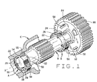
本発明は、数ある装置の中で、ハウジングC中でシャフトCを堅固に保持し、固定軸Xの周りにシャフトBを回転させる軸受A(図1)が有用であることを見出した。軸受Aは、シャフトBからハウジングCへの騒音の伝播を抑制する。ハウジングCは、トランスミッション中のギアシャフトの一つであるシャフトBを有する、トランスミッションのケーシングである。この例では、シャフトBのギアは、その周囲に沿った歯において、シャフトBに沿って伝わる騒音を生み、それは軸受Aを通ってハウジングCに伝播する。シャフトBはシート12とショルダー14を有し、ハウジングCは穴16と、穴16の一端でショルダー18を有している。軸受AはシャフトBのシート12に嵌合し、ハウジングCの穴16に収まっている。
The present invention has found that a bearing A (FIG. 1) that holds the shaft C firmly in the housing C and rotates the shaft B about the fixed axis X is useful, among other devices. The bearing A suppresses the propagation of noise from the shaft B to the housing C. The housing C is a transmission casing having a shaft B which is one of the gear shafts in the transmission. In this example, the gear of shaft B produces noise that travels along shaft B at the teeth along its circumference, which propagates through bearing A to housing C. The shaft B has a
軸受Aは、コーン22の形の内輪と、カップ24の形の外輪と、コーン22とカップ24の間に一列に並んだ円錐ころ26の形の転動体を有している(図2)。コーン22、カップ24、および、ころ26は、全て軸受鋼からできている。軸受Aは、同様にコーン22とカップ24の間に収まり、ころ6の間に適当な間隔を保つためにころ6を受けるポケットを有する、保持器28も有している。
The bearing A has an inner ring in the form of a
コーン22は、シャフトB上のシート12にぴったりと嵌まり、好ましくは締まりばめであり、また軸Xから離れて存在するテーパーされた軌道30を有している。軌道30の大端部では、コーン22は、軸Xに対して直角に切り落とされ、シャフトBのシート12の端部でショルダー14と接している背面34につながったスラストリブ32を有している。反対側の端部のコーン22は、同様にX軸に対して直角に切り落とされ、シャフトBに沿った橋台(abutment)に接触していてもいなくてもよい前面36を持つ。
The
カップ24は、ハウジングCの穴16に嵌め合っており、好ましくは締まりばめである。これは、X軸から離れて存在する外表面40を有し、穴16の表面と接している。これは、X軸とコーン22の軌道30の方へ内側に向いて存在し、さらにコーンの軌道30と同じ方向に傾斜している、テーパーされた軌道42も有する。外表面40とテーパーされた軌道42は、X軸に対して直角に切り落とされた背面44と前面46の間に広がっており、前者はハウジングCの穴の端部でショルダー18と接している。
円錐ころ26は、コーン22の軌道30とカップ24の軌道42の間に一列に並んでおり、それらのテーパーされた側面に沿って、軌道30と42に接している。大端面では、それらはスラストリブ32を支えており、スラストリブ32は、ころ26が2つの軌道30と42の間の輪状の空間から出るのを防いでいる。
The
実際には、シャフトBは、2つの軸受Aに支持されている。両者は非常に似ているが、2つの軸受は反対に取り付けられ、好ましくは予圧の状態でセットされる。軸受Aが寸法精度良く作られていると、X軸は安定する、すなわち、固定された位置にある。 In practice, the shaft B is supported by two bearings A. Both are very similar, but the two bearings are mounted oppositely and are preferably set with preload. If the bearing A is made with good dimensional accuracy, the X-axis is stable, i.e. in a fixed position.
シャフトBは機械的な振動を受け、それらは縦および横の力学的な波の形で騒音を生み出す。騒音はシャフトBに沿って伝わり、軸受のシート12でコーン22に入る。騒音はコーン22を半径方向に通り抜け、通り抜けてきたのと同様にして、軌道30でころ26に入る。騒音はカップの軌道42でカップ24に入り、カップ24を半径方向に通り抜け、外表面40へ行く。外表面40は、ハウジングCの穴16の表面ととまりばめであるので、騒音はカップ24からハウジングCへ伝わり、そしてハウジングCは騒音を受けるが、カップ24が減衰させる、すなわち騒音の多くを減衰させるので、騒音はそんなに強くはない。
Shaft B is subjected to mechanical vibrations, which produce noise in the form of longitudinal and transverse mechanical waves. The noise travels along shaft B and enters
この際、カップ24は外表面40に開口するいくつかのポケット50(図3、図4)を有しており、ポケット50はカップ24の円周に間隔を空けて、好ましくは等しい円周間隔で間隔を空けて存在している。ポケット50は、ころ26からカップ24へ通過する騒音を減衰させる役割を有し、このために、それらはできるだけ大きい円周領域を占めるようにされる。それでも、それらはシャフトBとハウジングCとの間のラジアル荷重を伝達する軸受Aの性能が損なわれないようにすべきである。すなわち、軸Xが安定に保持されるように、外表面40は、穴16にカップ24がしっかり保持される程度に十分大きくなければならない。
In this case, the
それぞれのポケット50の両端の間には、V字型の谷56を形成する並んだ溝を有する。それゆえそれぞれのポケット50に沿って、ポケット50につながっている外表面40に傾いており、また、ポケット50に向けられた力学的な波の伝播方向にも傾いている反射表面58を有する。谷56を越えて隣接している、傾斜した反射表面58の間のインクルーデッドアングルは30°〜90°の範囲である。谷56の左側の表面58は、谷56の右側表面と同じように、基本的にお互い平行である。頂点54は、外表面40によって形成される円筒枠より下方に位置しており、そのため頂点は、ハウジングCの穴16の表面に接触しない。反射表面58は、ポケット50に沿って、自由界面を形成しており、仮に何かあったとしても、それらは力学的な波をあまり伝えない媒体に沿って位置している。
Between both ends of each
軸受Aの作動中、シャフトB中の騒音はコーン22ところ26を通り抜け、カップの軌道42に沿ってカップ24に入る。この騒音は通常、縦および横の力学的な波の形で全てのラジアル方向に放射状に通り抜ける。縦波の方がはっきりとしていてより強い。一部の力学的な波は、外表面40とハウジングの穴16の表面との間の接触面で、ハウジングCに波が入る場所である外表面40まで広がる。残りの力学的な波は、ポケット50へ伝播する。ここで、縦波は傾斜表面58から反射し、部分的にモード変換を受ける。すなわち、異なる方向に伝播しカップ24自体の中で急激にエネルギーが消失する横波に変わる。
During operation of bearing A, noise in shaft B passes through
カップ24は、軌道42を保持しポケット50を有するスチールリング66および、リング66と嵌め合い、ハウジングCの穴16の表面と接している外表面40を与えるスリーブ68を有し、そのためスリーブ68が表面16とポケット50との間に介在し、頂点54がスリーブ68と接しないようにスリーブ68より内部に配されている、複合体(図5、図6)の形をとっていてもよい。スリーブ68は、エポキシ樹脂複合材料のような硬い樹脂から形成され、好ましくはリング66と接合している。実際には、これはリング66の周りに型形成され、そしてそれがポケットに入るのを防ぐために、ポケット50は発泡体のような低音響インピーダンス物質を詰められる。これはスリーブ68の硬い材料がポケット50の傾斜表面58や頂点54に接触するのを防ぎ、それによってポケット50における自由界面を維持している。
The
カップ24と一体的に形成する代わりに、傾斜表面58は、通常長方形の断面であるカップ24の空洞74に嵌合する挿入部72(図7)であってもよい。
Instead of being formed integrally with the
ポケット50中の溝52は、軸方向の代わりに環状(図8、図9)に広がっていてもよく、あるいは軸方向と環状の間のいずれかの方向のらせん状であっていてもよい。同様にして、挿入部72あるいはスリーブ68あるいはその両方が、環状あるいはらせん状の溝52と共に利用できる。
The
カップ24は、ラジアル荷重だけでなくスラスト荷重もハウジングCに伝え、これらのスラスト荷重は、ハウジングCの穴16の端部でカップ24の背面44と、ショルダー18とによって形成される接触面を越えて伝えられる。騒音もまた、特にスラスト荷重が重い場合にこの接触面を越えて伝播される。しかし、カップ24が背面44に開口したポケット50を有し、ハウジングCへの騒音の伝播を阻害してもよい。ポケット50は半径方向、環状、あるいはらせん状に広がっていてもよい溝52を有する。同様に、カップ24は、前面46に沿ってもう一つの橋台と接している場所で、前面46に開いているポケット50を有していてもよい。
The
シャフトBから発生する騒音の低減は、カップ24と一緒にコーン22の中で、あるいはコーン22の中単独でも起こってもよい(図10)。この目的のために、コーン22の穴は、コーン22の残りの部分に嵌合している鋼製スリーブ76の中に、すなわち、それに沿ってコーンの軌道30が位置しているスチールリング78の中に、位置している。好ましくは2つの間にエポキシあるいは他の一般的なポリマー組成物層80を有している。いずれにせよ、鋼製スリーブ76は、軸Xから離れているスリーブ76の外表面に開口しているポケット50を有し、ポケット50は、層80より内側に位置する頂点54と共に、軸方向、環状、あるいはらせん状に広がっている溝52を有する。
Reduction of the noise generated from the shaft B may occur in the
反対方向、すなわちハウジングCからシャフトBに騒音が軸受Aを通過する場合には、コーン22は、溝52の自由界面が軸Xの方へ向いて存在するように、その穴16に開いたポケット50を備えていてもよい。同様に、コーン22の背面34は、シャフトBのショルダー14を通る騒音の伝達を減らすためのポケット50を有していてもよい。さらに、内側への騒音の伝達は、軸Xの方へ内側に開き、V字型の溝を備えているポケット50を有するスリーブであって、カップ24の残り部分すなわち軌道42を有する部分を囲む鋼製スリーブ、を有するカップ24を備えることによってカップ24中で減らされてもよい。
In the opposite direction, i.e. when noise passes from the housing C to the shaft B through the bearing A, the
ポケット50は、他のタイプの転がり軸受にも有用である。例えば、アンギュラーコンタクト系、円筒ころ軸受、球面ころ軸受、針状軸受を含む玉軸受に使用されてもよい。それらは、スリーブ軸受、すなわち転動体を有さない軸受にさえも使用することができる。
The
騒音の低減は、騒音を実際に発生する部品の中で起こってもよく、一つの部品がもう一つの部品と接している表面に沿っている必要はない。例えば、平歯車84(図1)は、締まりばめでシャフトBと嵌め合っている。ここでギア84とシャフトBは接しており、そのため騒音は一方から他方へ伝わる。その外周に沿ってギア84は、もう一つのギアの歯と噛み合う歯86を有しており、歯86からシャフトBへ、縦および横の力学的な波の形で、内部に放射状に伝わる騒音に変わる振動を発生する。ギア84は、軸方向に広がっておりその端面で開口しているポケット50を有し、ポケット50は、軸Xに面した自由界面をもった溝を有する。ポケット50は、縦波をギア84自体の中で弱められる横波へと変換して、力学的な波の一部を遮る。
Noise reduction may occur in a part that actually generates noise, and one part need not be along a surface that is in contact with another part. For example, spur gear 84 (FIG. 1) is engaged with shaft B with an interference fit. Here, the
他方、ギア84は、シャフトBと嵌め合っている場所である穴に沿ったポケット50を備えていてもよい。これらポケット50の傾斜表面58の自由界面は、振動と騒音の発生源である歯84からみて外方に向いている。ポケット50は、シャフトBに放射状に向けられた一部の力学的な波を遮断し、シャフトBへの騒音の伝播を減らす。
On the other hand, the
軸受Aのコーン22が嵌め合っているシャフトBも、軸Xの外方に開いているポケット50を備え(図1)、そのため傾斜表面58がコーン22に向いて存在しているようにしてもよい。ポケット50は、シャフトBを通って伝播する波を遮断し、それらを部分的にシャフトB中で減衰する横波に変換する。
The shaft B in which the
一般的に言えば、ポケット50の中の傾斜表面は、ポケット50がどこに位置していようとも自由界面を有する。つまり、それらは、それに沿って空気、あるいは何かあったとしてもせいぜい低音響インピーダンスである発泡体のような物質、が存在する表面である。自由界面で表面58は、振動源から発生する入射する力学的な波の方向からみて外方を向いている。
Generally speaking, the inclined surface in the
Claims (25)
The machine part according to claim 24, wherein the machine part is made of steel.
Applications Claiming Priority (2)
| Application Number | Priority Date | Filing Date | Title |
|---|---|---|---|
| US10/086,038 US6616337B1 (en) | 2002-02-28 | 2002-02-28 | Noise-reducing machine component |
| PCT/US2002/029360 WO2003074892A1 (en) | 2002-02-28 | 2002-09-17 | Noise-reducing machine component |
Publications (2)
| Publication Number | Publication Date |
|---|---|
| JP2005519245A true JP2005519245A (en) | 2005-06-30 |
| JP2005519245A5 JP2005519245A5 (en) | 2006-01-05 |
Family
ID=27753781
Family Applications (1)
| Application Number | Title | Priority Date | Filing Date |
|---|---|---|---|
| JP2003573309A Pending JP2005519245A (en) | 2002-02-28 | 2002-09-17 | Noise reduction machine parts |
Country Status (5)
| Country | Link |
|---|---|
| US (1) | US6616337B1 (en) |
| EP (1) | EP1478864A1 (en) |
| JP (1) | JP2005519245A (en) |
| AU (1) | AU2002333665A1 (en) |
| WO (1) | WO2003074892A1 (en) |
Cited By (1)
| Publication number | Priority date | Publication date | Assignee | Title |
|---|---|---|---|---|
| JP2007218351A (en) * | 2006-02-16 | 2007-08-30 | Jtekt Corp | Rolling bearing device |
Families Citing this family (8)
| Publication number | Priority date | Publication date | Assignee | Title |
|---|---|---|---|---|
| US8311946B1 (en) | 1999-10-15 | 2012-11-13 | Ebrary | Method and apparatus for improved information transactions |
| EP1619416B1 (en) * | 2004-07-22 | 2008-11-19 | Eickhoff Maschinenfabrik GmbH | Compound ring gear |
| DE102004054974B4 (en) * | 2004-11-13 | 2015-04-02 | Schaeffler Technologies AG & Co. KG | rotary joint |
| US7857319B2 (en) * | 2006-06-08 | 2010-12-28 | John Crane Inc. | Mechanical seal with banded ring |
| AU2007319377A1 (en) * | 2006-11-10 | 2008-05-22 | Drs Rsta, Inc. | Bearing assembly having a flex pivot to limit gimbal bearing friction for use in a gimbal servo system |
| DE102011110871B4 (en) * | 2011-08-17 | 2018-12-06 | Neumayer Tekfor Engineering Gmbh | Built camshaft |
| CN106015523B (en) * | 2016-07-01 | 2018-04-17 | 东风商用车有限公司 | A kind of direct gear gear mechanism |
| DE102017100572A1 (en) | 2017-01-13 | 2018-03-01 | Schaeffler Technologies AG & Co. KG | roller bearing |
Family Cites Families (19)
| Publication number | Priority date | Publication date | Assignee | Title |
|---|---|---|---|---|
| US1579798A (en) | 1923-08-22 | 1926-04-06 | Henry A Vail | Antifriction bearing |
| US1965293A (en) * | 1931-04-22 | 1934-07-03 | Spontan Ab | Bearing |
| US2062290A (en) | 1933-09-14 | 1936-12-01 | Norma Hoffmann Bearings Corp | Journal bearing |
| US2244197A (en) | 1936-03-25 | 1941-06-03 | Hessler Christian Rudolph | Bearing |
| US2141122A (en) | 1937-12-22 | 1938-12-20 | Timken Roller Bearing Co | Cushioned roller bearing |
| US3698777A (en) | 1970-12-08 | 1972-10-17 | Timken Co | Tapered roller bearing with minimum heat generating characteristics |
| FR2144479A5 (en) | 1972-07-19 | 1973-02-09 | Timken Co | |
| DK142710B (en) | 1977-11-10 | 1980-12-29 | Elektronikcentralen | Sound absorbing structure. |
| DE3711359A1 (en) * | 1987-04-08 | 1989-01-26 | Helmut Pelzer | DAMPING AGENT FOR DAMPING SOUND RADIATION AS AIR SOUND OR BODY SOUND FOR WHEELS, IN PARTICULAR GEARS |
| GB8708772D0 (en) | 1987-04-13 | 1987-05-20 | Skf Uk Ltd | Bearing assembly |
| US5044789A (en) * | 1990-04-16 | 1991-09-03 | Eaton Corporation | Roller and ball bearing bearing isolator |
| US5044785A (en) | 1990-06-18 | 1991-09-03 | Eaton Corporation | Bearing isolator |
| US5044784A (en) | 1990-07-31 | 1991-09-03 | Eaton Corporation | Bearing isolator |
| US5078510A (en) | 1990-08-27 | 1992-01-07 | Eaton Corporation | Bearing isolator |
| US5657666A (en) * | 1994-10-25 | 1997-08-19 | Minolta Co., Ltd. | Transmission mechanism capable of suppressing vibrational noise |
| IT1289778B1 (en) | 1996-12-20 | 1998-10-16 | Skf Ind Spa | DEVICE FOR LOCKING AND UNLOCKING A GROUP OF COUPLING BETWEEN MECHANICAL PARTS USING A BISTABLE ELASTIC ELEMENT. |
| JP2000120670A (en) | 1998-10-19 | 2000-04-25 | Nsk Ltd | Rolling bearing |
| US6264370B1 (en) * | 1999-08-04 | 2001-07-24 | Meritor Heavy Vehicle Systems, Llc | Isolated bearing |
| US6536953B1 (en) * | 2000-11-08 | 2003-03-25 | E. I. Du Pont De Nemours And Company | Bearing mount system for reducing vibration |
-
2002
- 2002-02-28 US US10/086,038 patent/US6616337B1/en not_active Expired - Fee Related
- 2002-09-17 EP EP02807018A patent/EP1478864A1/en not_active Withdrawn
- 2002-09-17 JP JP2003573309A patent/JP2005519245A/en active Pending
- 2002-09-17 AU AU2002333665A patent/AU2002333665A1/en not_active Abandoned
- 2002-09-17 WO PCT/US2002/029360 patent/WO2003074892A1/en active Application Filing
Cited By (2)
| Publication number | Priority date | Publication date | Assignee | Title |
|---|---|---|---|---|
| JP2007218351A (en) * | 2006-02-16 | 2007-08-30 | Jtekt Corp | Rolling bearing device |
| JP4687494B2 (en) * | 2006-02-16 | 2011-05-25 | 株式会社ジェイテクト | Rolling bearing device |
Also Published As
| Publication number | Publication date |
|---|---|
| WO2003074892A1 (en) | 2003-09-12 |
| US20030161562A1 (en) | 2003-08-28 |
| US6616337B1 (en) | 2003-09-09 |
| EP1478864A1 (en) | 2004-11-24 |
| AU2002333665A1 (en) | 2003-09-16 |
Similar Documents
| Publication | Publication Date | Title |
|---|---|---|
| US3975894A (en) | Vibration and sound dampening means | |
| JP2005519245A (en) | Noise reduction machine parts | |
| JPS63254264A (en) | Damping means for damping propagation of sound of cycle | |
| US20150316135A1 (en) | Gearwheel for a backlash-free transmission stage and transmission stage equipped therewith | |
| US20150152940A1 (en) | Centrifugal force pendulum | |
| US20100046877A1 (en) | Rolling element bearing with reduced cage pocket clearance | |
| US3382017A (en) | Resiliently mounted axle bearing assembly | |
| US5078510A (en) | Bearing isolator | |
| JP2010090966A (en) | Damping structure | |
| WO2004051115A1 (en) | Flywheel | |
| JP2017026027A (en) | Rolling bearing | |
| JP2006170420A (en) | Outer ring for half-split bearing and half-split bearing provided therewith | |
| JP2005519245A5 (en) | ||
| JP2007177830A (en) | Dynamic damper and hollow propeller with it | |
| KR102346287B1 (en) | Dust cap for steering apparatus of vehicle | |
| JP4844095B2 (en) | Vibration transmissibility reduction device | |
| JP2005299837A (en) | Rolling bearing device | |
| JP3631902B2 (en) | Vibration reduction damper | |
| JP4468522B2 (en) | Gear transmission case | |
| JPS6311406Y2 (en) | ||
| JP4305213B2 (en) | Rolling bearing | |
| JPH0531304Y2 (en) | ||
| WO2023120222A1 (en) | Center bearing support | |
| JP2024068917A (en) | Dynamic vibration absorber | |
| KR102289833B1 (en) | Dynamic damper for hollow drive shaft |
Legal Events
| Date | Code | Title | Description |
|---|---|---|---|
| A521 | Written amendment |
Free format text: JAPANESE INTERMEDIATE CODE: A523 Effective date: 20050901 |
|
| A621 | Written request for application examination |
Free format text: JAPANESE INTERMEDIATE CODE: A621 Effective date: 20050901 |
|
| A131 | Notification of reasons for refusal |
Free format text: JAPANESE INTERMEDIATE CODE: A131 Effective date: 20080304 |
|
| A601 | Written request for extension of time |
Free format text: JAPANESE INTERMEDIATE CODE: A601 Effective date: 20080520 |
|
| A602 | Written permission of extension of time |
Free format text: JAPANESE INTERMEDIATE CODE: A602 Effective date: 20080612 |
|
| A02 | Decision of refusal |
Free format text: JAPANESE INTERMEDIATE CODE: A02 Effective date: 20090203 |