JP2005507724A - User interface and method of sedation and analgesic delivery system - Google Patents
User interface and method of sedation and analgesic delivery system Download PDFInfo
- Publication number
- JP2005507724A JP2005507724A JP2003540765A JP2003540765A JP2005507724A JP 2005507724 A JP2005507724 A JP 2005507724A JP 2003540765 A JP2003540765 A JP 2003540765A JP 2003540765 A JP2003540765 A JP 2003540765A JP 2005507724 A JP2005507724 A JP 2005507724A
- Authority
- JP
- Japan
- Prior art keywords
- user
- patient
- sedation
- analgesia
- alarm
- Prior art date
- Legal status (The legal status is an assumption and is not a legal conclusion. Google has not performed a legal analysis and makes no representation as to the accuracy of the status listed.)
- Granted
Links
Images


Classifications
-
- G—PHYSICS
- G16—INFORMATION AND COMMUNICATION TECHNOLOGY [ICT] SPECIALLY ADAPTED FOR SPECIFIC APPLICATION FIELDS
- G16H—HEALTHCARE INFORMATICS, i.e. INFORMATION AND COMMUNICATION TECHNOLOGY [ICT] SPECIALLY ADAPTED FOR THE HANDLING OR PROCESSING OF MEDICAL OR HEALTHCARE DATA
- G16H40/00—ICT specially adapted for the management or administration of healthcare resources or facilities; ICT specially adapted for the management or operation of medical equipment or devices
- G16H40/60—ICT specially adapted for the management or administration of healthcare resources or facilities; ICT specially adapted for the management or operation of medical equipment or devices for the operation of medical equipment or devices
- G16H40/63—ICT specially adapted for the management or administration of healthcare resources or facilities; ICT specially adapted for the management or operation of medical equipment or devices for the operation of medical equipment or devices for local operation
-
- G—PHYSICS
- G16—INFORMATION AND COMMUNICATION TECHNOLOGY [ICT] SPECIALLY ADAPTED FOR SPECIFIC APPLICATION FIELDS
- G16H—HEALTHCARE INFORMATICS, i.e. INFORMATION AND COMMUNICATION TECHNOLOGY [ICT] SPECIALLY ADAPTED FOR THE HANDLING OR PROCESSING OF MEDICAL OR HEALTHCARE DATA
- G16H20/00—ICT specially adapted for therapies or health-improving plans, e.g. for handling prescriptions, for steering therapy or for monitoring patient compliance
- G16H20/10—ICT specially adapted for therapies or health-improving plans, e.g. for handling prescriptions, for steering therapy or for monitoring patient compliance relating to drugs or medications, e.g. for ensuring correct administration to patients
-
- G—PHYSICS
- G16—INFORMATION AND COMMUNICATION TECHNOLOGY [ICT] SPECIALLY ADAPTED FOR SPECIFIC APPLICATION FIELDS
- G16H—HEALTHCARE INFORMATICS, i.e. INFORMATION AND COMMUNICATION TECHNOLOGY [ICT] SPECIALLY ADAPTED FOR THE HANDLING OR PROCESSING OF MEDICAL OR HEALTHCARE DATA
- G16H15/00—ICT specially adapted for medical reports, e.g. generation or transmission thereof
Landscapes
- Engineering & Computer Science (AREA)
- Health & Medical Sciences (AREA)
- Primary Health Care (AREA)
- Biomedical Technology (AREA)
- Public Health (AREA)
- Epidemiology (AREA)
- General Health & Medical Sciences (AREA)
- Medical Informatics (AREA)
- General Business, Economics & Management (AREA)
- Business, Economics & Management (AREA)
- Chemical & Material Sciences (AREA)
- Bioinformatics & Cheminformatics (AREA)
- Medicinal Chemistry (AREA)
- Measuring And Recording Apparatus For Diagnosis (AREA)
- Infusion, Injection, And Reservoir Apparatuses (AREA)
- Management, Administration, Business Operations System, And Electronic Commerce (AREA)
- Media Introduction/Drainage Providing Device (AREA)
Abstract
本発明は、鎮静および鎮痛を送出するシステムおよび方法のユーザインタフェースを含む。ユーザインタフェースは、鎮静および鎮痛送出システムのユーザから入力を受け取り、システム、鎮静および鎮痛の施行、生理学的状況に関連する情報を状況依存的にユーザに中継して伝える。中継して伝えられる情報は、タッチセンシティブスクリーンまたは多層ディスプレイ装置上でユーザに表示することができる。表示は、組織配列上で分離したり、または表示装置上で色分けすることができ、表示された情報の組織配列での場所および/または色がさらなる情報をユーザに関連させる。The present invention includes a user interface for a system and method for delivering sedation and analgesia. The user interface receives input from the user of the sedation and analgesia delivery system and relays information related to the system, sedation and analgesia enforcement, and physiological conditions to the user in a context-dependent manner. The relayed information can be displayed to the user on a touch-sensitive screen or a multi-layer display device. The display can be separated on the tissue array or color-coded on the display device, where the location and / or color of the displayed information in the tissue array correlates further information to the user.
Description
【技術分野】
【0001】
本願は、米国特許法119条(e)の下で、2001年11月1日に出願され、その全体が参照により本明細書に援用される米国特許出願第60/330,853号に対する優先権を主張するものである。
【0002】
[発明の分野]
本発明は、包括的には、医療装置制御の分野および臨床医(一人または複数)が同時に複数の作業を遂行することができる患者−臨床医−機械システム内での相互作用を向上させる分野に関する。より詳細には、本発明は、鎮静および鎮痛送出システム等の医療装置のユーザインタフェースおよび制御方法に関する。
【0003】
[発明の背景]
臨床医用にユーザインタフェース(UI)を設計することは、多くの臨床医が広範囲にわたる勤務時間中に座る時間または忍耐を有してない場合があるため、特に扱いにくい課題である。臨床医の中での一観点によれば、ある緊急の状況では、そのマニュアルがすぐに手に入らないか、臨床医がそれについて十分に訓練を受けていない、すなわち技能維持に最近その装置を使用していないときに、装置の操作が必要となる可能性があるため、医療装置の操作にマニュアルを読む必要があるならば、その装置の設計者は落第である。多くの医療装置は、この実際的な現実世界での直観性および有用性の定義を欠いている。有用性が不十分であることが臨床処置の最終的な結果に影響する可能性があるとすると、臨床医のニーズを見越した、うまく設計されたユーザインタフェースが極めて重要である。
【0004】
安価なマイクロプロセッサの出現に伴い、ソフトウェアにプログラムされたUIの柔軟性および性能により、より多くのコマンドを実装し、より多くの選択肢および動作モードをユーザに提供するUIを設計する可能性が開けた。しかしながら、既存の特定の装置のインタフェースでは、こういったコマンドはサブメニューという多くの階層レベルの下に隠れ、ユーザに対してすぐに、または直観的に明確になっていないものがある。一方で、コマンドセットがキーパッドまたは論理的なメニュー構造において臨床の観点から論理的にグループ化されていない場合があり、そのため、ユーザが複数のボタンおよびサブメニュー選択肢を移動する際に道筋に迷う恐れがある。同様に、複数の操作モードが、現在実行されている操作モードをたどることをできなくなるユーザを混乱させる恐れがある。たとえば、実際の患者に接続されているのに、不注意でシミュレーションモードで実行されている生理学的モニタはユーザを混乱させる恐れがあり、モニタに表示されているデータが、モニタに接続されている患者からのデータではなくシミュレーションデータであった場合、危険である。
【0005】
タッチスクリーン入力デバイスは、新たなハードキーまたは入力デバイスを追加する必要なく、実質的に無限数のタッチスクリーンボタンまたはデータ入力ボックス、ならびに急場しのぎのソフトウェアでの追加物を実装する能力を含め、UI設計者に柔軟性をもたらす。したがって、タッチスクリーンによって制御されるデバイスは、関連するハードキーの数が少ないという傾向を有する。ユーザインタフェース設計の技術分野では、競合する要因のバランスを慎重にとることが必要である。たとえば、タッチスクリーンキーへの依存度が増すと、サイズの限られた1つの画面上にすべてのキーを表示することは通常許されないため、サブメニューの階層レベルの数が多くなることにつながりうる。しかしながら、ハードキーの数が少ない場合には、医療装置がタッチスクリーンキーに依存してしまい、タッチスクリーンが誤作動した場合にその医療装置が作動しなくなり、ユーザがもはやシステムの動作を制御することができなくなることを意味する。
【0006】
既存の医療装置に伴うさらに別の例では、別々の生理学的モニタが、互いに通信しないスタンドアロン型ユニットである場合がある。スタンドアロン型モニタは、異なる場所にある異なる機器の異なる位置に配置される可能性があるため、手術場所に基づいて複数のオフィスで開業している臨床医が、たとえば心電図を検査するために施設ごとに異なる場所を見る必要がある場合があり、これは決して望ましい状況ではない。複数の生理学的パラメータ(たとえば、心電図、パルスオキシメトリデータ、非侵襲性血圧、およびカプノメトリの読み)を監視しなければならないことを考えると、入手可能なデータを見つける臨床医の能力ですらかなり限定される恐れがあり、ましてやリアルタイムベースで関連情報を認知的に統合して解析することなどできない。さらに、麻酔機の例を用いると、送出サブシステムの監視される機器パラメータ(たとえば、O2およびN2Oの浮子式ロタメータセッティングによって設定される吸入酸素濃度)が、これに対応する監視中の生理学的パラメータである動脈血中酸素飽和度、SpO2から物理的に切り離される恐れがある。一例として、監視されるSpO2値は、送出される吸入酸素濃度(FiO2)の状況の中で解釈されるべきである。したがって、FiO2セッティング(機器パラメータ)とSpO2の表示(関連する生理学的パラメータ)が切り離されること、およびより一般的には医療装置において治療と監視されている対応するパラメータとが切り離されることは望ましくない。
【0007】
UIは、操作の透明性を向上させるため、ならびにユーザの要求が実行されたフィードバックを提供するために、医療装置の内部機能へのウィンドウとしての重要な機能を有することができる。透明性欠如の一例として、多くの既存の患者監視装置では、モニタの電源が切られたかまたはモニタが待機モードになっているときでさえ、断続的に取り込まれた古いデータが表示され続ける。ユーザがモニタの電源を切った後で再び電源を入れるのを忘れた場合、UIに、極めて重要な診断の決定および治療の決定に関連するその時の生理学的データが表示されているとユーザが勘違いする恐れがある。
【0008】
適切に設計されたUIは、臨床医−機械−患者システム内の相互作用を高めるべきである。ユーザの認知的な作業負荷または「データ過負荷」を軽減するために、UIは、生データを提示する代わりに、すでに処理されて一見して理解することができる意味のある情報になったデータを提示し、それによって適時の決定支援をユーザに提供すべきである。
【0009】
ユーザエラーは、わかりやすく明白な制御機構および入力デバイスによって回避することができる。しかしながら、現在のUI設計には他の故障モードが存在する。たとえば、デフォルト設定が、注入ポンプによって実証されているように小事故の原因となる場合がある。ユーザが、実際には、実際の薬物濃度よりも低いデフォルト濃度を誤って受け入れてしまうと、薬物の過剰投与、そして死亡に繋がる。単位(units)間の混乱もまた、特に、重量が薬物注入流量の算出に使用されることがある状況でエラーの原因になる可能性がある。
【0010】
UIは、記憶の負荷を低減するだけではなく、ユーザの忘れっぽさ、不正確なデータ入力、および判断力のなさを補うべきである。現在のUIによっては、複数のアラームがある場合に、時にはイライラさせるアラームの不協和音の真っ直中でどのパラメータ警報を出しているかを特定する際、ならびに最も優先度の高いアラームを決定する際に、装置の環境または表示をサーチする必要がある。現在のUI設計でのアラームは時折、脈絡なくアラームを生成することがある。たとえば、患者が医療装置に接続されていないとき、または処置の終わりにおいて患者が装置から外されようとするときにアラームが鳴ることがあり、これらはアラームが、すでにわかっている何かをユーザに伝えることで迷惑になるアラームのこの上ない例である。
【0011】
[発明の概要]
本発明は、鎮静および鎮痛についての経験があったり、またはなかったりする臨床医がシステムを容易かつ安全に操作できるようにする、鎮静および鎮痛送出システムのユーザインタフェースを包含する。このユーザインタフェースは、鎮静および鎮痛処置に関わるプロセスについて、またはこのプロセスと相互作用する情報を示す、いくつかは状況依存式であることができる、いくつかの異なるウィンドウを表示可能なタッチスクリーン等の対話式装置と、タッチスクリーン上に何が表示されているかに関わりなく、システムの主要機能を起動または停止するいくつかのボタンからなる別個のキーパッドとからなる。表示は、Deep Video Imagingから入手できるもの等、高いデータ密度を実現しやすくする多層ディスプレイであってもよい。
【0012】
UIの表示は、患者モニタからのデータ(たとえば、心拍数、血圧、SpO2、ETCO2、および自動反応性試験(「ART」))および治療データ、すなわち薬物およびガスの送出に関連する情報を両方とも単一の画面上に配置し、この情報はグループ化されて、意味のある認知的な枠組みをユーザに提供する。たとえば、心臓血管/血流力学システムを理解する基礎を提供する、監視される生理学的パラメータが、単一のかたまり、まとまり、または単一のラインにグループ化される。同様に、情報は、酸素供給状態、換気状態、および薬物の作用を解析するユーザのメンタルモデルの実現に役立つように一緒にグループ化される。データは、処置全体を通して常に更新される。メンタルモデルの実現に役立つ状況では、患者パラメータの現在データは数値および図表波形の両方として表示される。ユーザによる参照および比較のため、ならびに傾向検出のために、履歴データも提示される。履歴データは、心拍数、SpO2、およびEtCO2の量および変化率についての情報を提供し、緊急時に助けに来た、または手術もしくは他の処置に専念していた臨床医が患者の状態を一見して迅速に評価することができるようにする。
【0013】
UIは、タッチスクリーンの組織配列上で、ユーザが各種ソースから報告されたデータを容易に比較することができるように患者のデータを表示する。そして、ユーザは、器具で一杯の部屋を見回して、異なるデータ間の関連付けまたは相互確認を行う必要がない。さらに、UIは、治療制御およびモニタデータを同じUI上に提示しながら、情報の組織配列ならびに色分けも利用する。たとえば、システムは、一貫したタイムラインに沿った薬物動態学的計算に基づいて、生理学的データ(たとえば、心拍数、SpO2、ECG、CO2等)の表示を薬物レベルの表示と統合し、それによってユーザがこれらパラメータを相互に関連付けられるようにする。
【0014】
UIは、患者状態アラームおよびシステム助言の容易な管理および提示を可能にする。UIの表示は、現在のアラームおよび助言のすべてがそれぞれの優先度に従って表示される専用部分を含む。ユーザは、画面上の1つの中心場所を見る必要があるだけであるため、すべてのアクティブな警告に遅れをとることがない。UIは、アラームおよび助言に、限られた時間の間ユーザが消音化することができる何重もの(redundant)音声警告をも提供する。警告を忘れないのを確実にするため、ユーザには消音化アラームに残っている残り時間が提示されるが、ユーザは、音声警告が鳴らないようにする予測的な(proactive)ステップを行わなければならない。
【0015】
鎮静および鎮痛処置の準備および施行(administration)中、ユーザが極めて重要な設定を変更するとき、入力エラーの可能性を低減するために、UIはユーザの行為を確認するプロンプトをユーザに表示する。ユーザには、要求された特定の行為の結果リストが提示され、システムが薬物を患者に投与する前に、鎮静および鎮痛の安全のための特定の必要前提条件が満たされているかチェックすることを思い出させる。
【0016】
システムは、有毒になる可能性のある薬物の用量の入力、一貫しない患者データの入力、または必要前提条件を最初に満たさずしての鎮静および鎮痛の開始等、ユーザが患者にとって危険である可能性のある特定の行為をとる場合、UIを介してユーザに警告し、鎮静および鎮痛の進行を許可しない。しかしながら、システムの設計はまた、「臨床医が一番よくわかっている」という見解に従う。換言すれば、ソフトウェアに考えられるすべての条件の組み合わせ、および条件の順列を見越させようと試みるのではなく、設計は、前もって、考えられる臨床状況をすべて見越すことができるわけではなく、適切なデータが与えられている場合、患者を引き受けている臨床医のほうが、予め定められたシステムアルゴリズムよりも良好な判断を下すということを認めている。
【0017】
鎮静および鎮痛中に薬物の滴定を行うなど時間および労力集約的な作業は、臨床上の発見的方法(heuristics)ならびにとりわけ薬物動態学モデルおよび目標制御静脈薬物注入に基づくことができる薬物状態モデルを賢く使用することによって部分的に自動化される。薬物注入の停止のような、安全な作用をもたらす可能性の高い行為のみが自動化される。目標制御注入(TCI)もまた、ユーザが時間の経過に伴う所望の注入流量プロファイルを算出する必要がある代わりに(これは、行うことが非常に難しく、また実施が面倒であり時間がかかる)、ユーザインタフェースが、TCIアルゴリズムと併せて、鎮静および鎮痛中に薬物の滴定を行うユーザフレンドリな方法および時間および労力集約度がはるかに低い方法を提供するため、ユーザインタフェースを向上させる方法の1つである。
【0018】
目標制御注入および臨床上の発見的方法は、薬物状態モデルで組み合わせられる。薬物状態モデルは、鎮静および鎮痛送出システムのUI、ARTモニタ、および薬物送出装置にも密に統合され、不注意により患者が意識不明に陥ってしまうことの回避に必要な時間および労力を低減する。
【0019】
臨床医によっては、コンピュータシステムが人間による監督なしで効力のある薬物の送出を制御することに疑いを持っている者もいる。UIは、適切な人間による監督になお対応しながら、薬物の滴定を行うなど時間および労力集約的な繰り返し作業を低減するなど、臨床上の発見的方法によってコンピュータ制御の恩恵を提供するシステム設計をサポートする。
【0020】
反対に、過度に保守的で安全偏重の臨床上の発見的方法アルゴリズムは、当面の疼痛処置を見越して、刺激を受けていない患者には意識消失を引き起こすであろう量の薬物を意図的に与えるなど、ユーザが特定の行為を実行しないようにして処置の臨床過程を妨害する場合がある。UIは、場合によっては、その前にメッセージをユーザに提供して本当にこれを行いたいのか確認し、また臨床医が安全偏重の発見的方法およびアルゴリズムをオーバーライドできるようにし、同様に提案されている行為の結果を説明することによってこのような臨床状況を見越す。
【0021】
UIは、特定のデフォルトが放棄されたことにシステムの考えられるユーザすべてが気付くことができるように、システムの設定に対して行われたあらゆる変更についての常時通知も提示する。多くの場合、システムの現在の状態またはシステムの機能の予期される達成についてのユーザの知識は、同じ情報の特性を示す何重ものアイコンおよびテキストをUIが表示することによって強化される。
【0022】
鎮静および鎮痛または麻酔薬および滴定薬を送出するという施行に時間のかかる局面の多くは、制御ソフトウェアにプログラムされた臨床上の発見的方法および薬物状態モデルを使用して自動化される。UIは、ユーザが医療装置をその潜在能力を最高まで使用することを妨げないように、ユーザが予めプログラムされた発見的方法をオーバーライドできるようにしながら、臨床上の発見的方法アルゴリズムおよび目標制御注入に対応するように設計される。
【0023】
[発明の詳細な説明]
機能的に鎮静および鎮痛送出システムに統合することができるユーザインタフェース(UI)について本明細書に述べる。このような鎮静および鎮痛送出システムの一例は、1999年6月3日に出願され、その全体が参照により本明細書に援用される米国特許出願第09/324,759号に記載されている。
【0024】
出願第09/324,759号の鎮静および鎮痛システムは、患者に接続され、患者の少なくとも1つの生理学的状況を反映した信号を生成するようになっている患者健康状態モニタデバイスと、1つまたは複数の薬物を患者に供給する薬物送出コントローラと、患者の監視される少なくとも1つの生理学的状況の安全なパラメータおよび望ましくないパラメータを反映した安全データセットを格納したメモリデバイスと、患者健康状態モニタ、薬物送出コントローラ、および安全データセットを格納したメモリデバイスの間に相互接続される電子的コントローラと、を備え、上記電子的コントローラは上記信号を受け取り、これに応答して、安全データセットに従って薬物の適用を管理する。
【0025】
図1は、UI1、電子的コントローラ4、周辺機器5、電源6、患者インタフェース7、および薬物送出器9を備えた、本発明によるこのような鎮静および鎮痛システム2の一実施形態を表すブロック図を示し、鎮静および鎮痛システム2は、鎮静および/または鎮痛を患者8に提供するためにユーザ3によって操作される。本発明のUI1と併用する鎮静および鎮痛送出システム2は、取り外し可能な、または使い捨ての薬物瓶とともに使用してもよく、また再利用可能な、または使い捨ての薬物カセットとともに使用してもよい。送出システム2には、患者8の患者インタフェース7の一例である自動化反応性試験(ART)を設けてもよい。送出システム2のART機能の例は、2001年12月28日に出願され、参照により本明細書に援用される米国特許出願第60/342,773号に記載されている。
【0026】
プロポフォール、レミフェンタニル、ケタミン、デキサメデトミジン、フェンタニル、モルヒネ、亜酸化窒素等の様々な薬物を送出システム1によって投与する、または送出システム1と併せて使用することができる。単に例示を目的として、UI1は本明細書では、プロポフォールを投与するシステムと併せて使用することができるものとして説明する。UI1は、臨床医ユーザ3に、予測される薬物の効果部位濃度を変更する注入アルゴリズムを含め、鎮静および鎮痛送出システム2の様々な特徴および能力の制御を提供する。このような特徴の例としては、2002年7月31日に出願され、参照により本明細書に援用される米国特許出願第10/208,183号に記載の薬物送出モードおよび薬物状態(state)が挙げられる。
【0027】
UI1の態様の多くは、鎮静および鎮痛の経験があったり、またはなかったりする臨床医にとって、おそらく複数の作業を行いながら、鎮静および鎮痛送出システム2を容易に操作するのに有用なように設計される。このような有用性を提供するUI1の1つの一般的な特徴は、送出システム2の安全アルゴリズムがそれぞれのデフォルト設定から変更されたときはいつでもユーザ3に一貫して常時警告することである。UI1の別の一般的な特徴は、真に意図する行為のみが送出システム2によって実施されることをチェックするさらなる機会をユーザ3に与えるように、ユーザ3が行う特定の行為を確認するようユーザ3に要求することである。UI1のこのおよび他のすべての確認画面に共通するのは、ユーザ3が先に開始したコマンドを確認するために触れる確認タッチボタンの位置が、コマンドを開始するためにユーザ3が最初に触れた開始ボタンと同じタッチスクリーンエリアに表示されないということである。この配置の相違により、ユーザ3が、単に指が開始ボタンと同じ画面上の位置に残っていただけのために、自動的に、すなわち不注意に確認ボタンに触れて承認してしまうことがないのを確実にすることができる。また、開始および確認タッチボタンの位置が異なる場所にある場合、開始および確認タッチボタンの互いの位置関係は、開始/確認タッチボタンの異なるセットを通して不変であることができる。
【0028】
UI1の別の一般的な特徴は、ユーザ3に対して表示される特定の情報が、グループ、位置、または配色から意味を引き出すことができるようにグループ化または配置されてユーザ3に表示されることである。これら一般的な特徴の例は、後述するUI1の特定の実施形態によって表される。
【0029】
図2は、他のタイプの入力デバイス(たとえば、固定式メンブレンキーパッド)では不可能でありうる、ユーザ3が直接かつ直観的に送出システム2のソフトウェアと状況依存的に相互作用するために設けることができる、タッチスクリーン入力デバイス90のエリアを示す。これらエリアはタッチセンシティブであり、3Dボタン10として、またはテキスト入力タッチボックス12としてユーザ3に提示することができる。エリアは、常に状況およびユーザ3に表示される情報のフォーマットに応じて様々である。ユーザ3によるコマンドの入力は、このようなコマンドに指定された3Dボックスに触れることによって実現することができる。データの入力は、所望のテキスト入力ボックス12に触れ、それからメンブレンキーパッドを介して、または画面上に表示されるタッチボックスキーパッドを介してデータを入力することによって実現することができる。
【0030】
図2は、送出システム2が、UI1を介して音声および/または視覚的なフィードバックを表示することにより、このテキスト入力ボックスの起動についてユーザ3に確認することができることも示す。たとえば、触れられると、3Dタッチボタン12の外観は反転画像14または他の変更版に変更することができる。テキスト入力ボックス起動に対する視覚的なフィードバックは、テキスト入力ボックス16のハイライトにより、かつ/またはカーソルの外観によって提供することができる。テキスト入力ボックスが起動されると、可聴クリック音等の音も再生して、ユーザフィードバックをさらに強化することもできる。ユーザ3が指をボタンから離すと、システムは機能を起動し、音声での合図を提供する。ユーザ3が指をボタンから滑らせて外すと、システムはボタンのハイライトを消し、それ以上行為は行われない。
【0031】
図3は、ユーザ3がデータを入力し、極めて重要な機能を起動することができるように、送出システム2のコンソール上に設けることができる固定式メンブレン(membrane)キーパッド34を示す。メンブレンキーパッド34上のキーは、それぞれの場所を触知できるように、それぞれを取り巻く隆起線を有することができる。ある特別な、または多くの場合に使用されるメンブレンキー(たとえば、特に「はい(OK)」、「キャンセル(Cancel)」、「<」、「>」および電話式番号配列の中央にある番号「5」)は、隆起したドット、ダッシュ、または他のこのような構造のような特徴的な触知可能要素を有して、ユーザ3が、実際にタッチスクリーン表示から目を離してキーパッドを見る必要なく、どのメンブレンキーに触れているかわかるようにすることができる。メンブレンキーは、触知できるクリックの前にメンブレンを物理的に動かすことを介して、起動(activation)フィードバックを有することもできる。送出システム2は、UI1のキーが起動されたときに、音声トーンを再生することも可能である。これら特徴により、キーパッド34上のボタンの押下で機能が起動されたという保証がユーザに与えられる。キーパッド34は、ユーザ3が容易に交換可能な、様々な言語でプリントされたオーバーレイを受け入れることができる。
【0032】
図3に示すように、キーパッド34は、標準的な数値キーパッド36、タブ35、前進矢印37、後進矢印39、および/またはデータ入力用のバックスペース41を備えることができる。起動されると、送出システム2を、それまで非アクティブであった場合は起動シーケンスに、それまでアクティブであった場合は待機モードおよびシャットダウンシーケンスにするシステムオン/オフ(On/Off)またはオン/待機(On/Standby)ボタン38が設けられる。送出システム2の多くの必要な機能は、それぞれを直接起動する専用ボタンをメンブレンキーパッド34上に有しうる。これらボタンにはテキストおよびアイコンの両方でラベル付けすることができ、点灯しているときは、対応する機能がアクティブであることを示す色付きLEDを関連付けることもできる。肯定40および非肯定42応答用のハードボタンは、タッチスクリーン上の「はい」、「いいえ(No)」、および「キャンセル(cancel)」タッチボタンに対応してキーパッド上に含めることができる。タッチスクリーン900のタッチセンシティブ機能が誤作動することがあっても、これらハードキーパッドボタンは、ユーザ3がそれでも、UI1の様々な表示に対してはい、いいえ、およびキャンセル要求に応答できるようにする役割を果たす。これらボタンは、システムメッセージおよび画面に応答する際に使用しやすさも提供する。
【0033】
新しい鎮静および鎮痛処置の開始に関連するシステム機能の起動用に、様々なシステムキーをキーパッド34上に設けることができる。このようなキーの例としては、患者情報(patient Info)17、システム情報(system info)43、スケール変更(change scales)302、音声ボリューム(audio volumes)301、新規ケース(new case)15、およびケース終了(end case)19が含まれる。これらのキーは、メンブレンキーパッド34の共通部分44内にグループ化される。これらのキーに関連するシステム機能については詳細に後述する。患者へのプロポフォールの投与に関連する機能の起動用に、他の様々なキーも設けることができる。このようなキーの例としては、パージIVライン(purge IV line)51、通常モード(normal mode)47、スタットモード(stat mode)49、およびプロポフォール停止(stop propofol)53が含まれる。これらのキーに関連するシステム機能については詳細に後述する。これらのキーは、メンブレンキーパッド34の共通部分46内にグループ化される。キーパッド46のプロポフォール送出セクションに隣接して一連のLED48を設けることができ、このLED48は、各LEDが点灯する時間量が、患者8に現在投与されているプロポフォールの注入流量に反比例するように、順次、たとえば米国およびテキストを左から右に読む国々では左から右に点灯する。代替として、LED配列を、薬物注入に通常関連するドリップチャンバのメンタルモデルを反映するように、上から下という順序で点灯してもよい。キーパッドのプロポフォール部分に隣接して、薬物カセットが送出システム2のハウジングの位置に適切に装填されたときに点灯する別のLED50も設けることができる。LED50は、カセットが正しく配置されているときは特定の色(たとえば、緑)で点灯し、カセットが存在するが、装填が正しくないとき、またはシステムコントローラ4により有効ではないと判定されたカセットであるときは別の色(たとえば、赤)で点灯することができる。プロポフォール瓶の位置および有効性を表す同様のLED52も設けることが可能である。
【0034】
引き続き図3を参照すると、アラームに関連するシステム機能の起動用に様々なキーを設けることができる。このようなキーの例としては、特に、アラーム消音(mute alarms)13、アラーム一時停止(suspend alarms)11、およびアラーム設定(alarm settings)45が含まれる。これらのキーに関連するシステム機能については詳細に後述する。これらのキーは、メンブレンキーパッド34の共通部分54内にグループ化される。
【0035】
ECG、SpO2、およびCO2モニタ等、患者健康状態モニタの起動用にキー56を設けることができる。各モニタのオン/オフトグルキー56等のスイッチにより、ユーザは各モニタを独立してオンまたはオフすることができる。モニタがオンのときに点灯する、LED58等、関連するインジケータを、各モニタに設けることができる。
【0036】
送出システム2のART機能用にオン/オフトグルキー56aも設けることができる。起動されると、送出システム2にARTクエリデバイスをオンにさせ、即座に反応性試験を施行させるARTスタットキー60も、オン/オフトグルボタン56aに隣接して設けることができる。ユーザの要求により、ARTスタット機能は、ユーザに、鎮静および鎮痛の開始前であっても、また単に教育目的のため、またはベースラインとなるART反応時間を設定するためだけであっても、ユーザが随時試験を開始できるようにすることによって患者が反応性試験に対する反応の仕方を学習するのに役立つ。ARTのセットアップキー62も、トグルキー56aおよびスタットキー60に隣接してキーパッド上に含めることができる。ARTセットアップについては詳細に後述する。
【0037】
同様のオン/オフ、スタット、およびセットアップキーを、システムの非侵襲性血圧(NIBP)機能用に設けることもできる。スタットNIBPおよびNIBPセットアップについては、詳細に後述する。同様のオン/オフ、スタット、およびセットアップキーを、システムのプリント機能用に設けることもできる。スタットプリントキーが起動されると、スタットプリントアウト画面(図31)がユーザに表示される。プリントセットアップについては詳細に後述する。点灯時、システム全体が故障していることを表すLED64、および/または点灯時、A/C電源が存在し、システムバッテリが充電中であることを表すLED66も、メンブレンキーパッド34に設けることができる。
【0038】
ECG、SpO2、CO2、NIBP、およびARTモニタの個々のオン/オフハードボタンにより、侵襲的血圧モニタがすでに心臓カテーテルラボに存在する場合、NIBPモニタをオフにするなど、システムを既存のモニタ機器に適合させるように独立してオフにすることができる。ケース終了時に患者から取り外されるときに個々のモニタをオフにすることができることにより、不適切かつ苛立たしいアラームの発生が低減されるとともに、処置の開始を待っている間に、不適切なアラームなしで、処置およびその後に続く個々のモニタの一時停止前にベースラインデータを取り込んでプリントすることができる。また、UI1のこの特徴により、ユーザ3は、患者の生理学的状況により不適切であると示される特定の場合に特定のモニタを使用しないことができる。誤りかつ不適切なアラームの別のコンテキストは、モニタがオンになっているが、患者が接続されていない場合である。たとえば、CO2モニタは、所与の時間量の間、特定のしきい値を越える呼気CO2がない場合に無呼吸アラームを鳴らしうる。UI1はまた、患者が鎮静および鎮痛機に接続されていない間に、ユーザがモニタをオフにする、またはアラームを一時停止できるようにして、誤ったアラームの発生を低減する。
【0039】
図3は、補充O2送出システム用に設けることができるオン/オフトグルキー56bも示す。補充O2送出システムがオンになっているときに点灯する、関連するLED58bも設けることができる。プリントオン/オフボタン56cを介して、自動プリントを選択または選択解除することができる。
【0040】
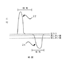
図4は、補充O2送出システムが起動されているときの、O2の固定高流量および固定低流量それぞれを示す呼吸圧曲線を示す。補充O2送出システムが特定の期間にわたり(たとえば、少なくとも30秒)、雰囲気圧以下、または正圧を記録しないとき、すなわち、患者が無呼吸であるか、あるいは自分の口で呼吸しているとき、固定中間流量のO2を患者に送り込ませる。鼻および口のカプノメータが両方とも、中間流量期間中に少なくとも2分間呼吸数を検出しない場合、補充O2送出システムは、補充O2送出をオフにしてO2を節約する。このシステムは、自動補充O2送出を提供し、O2投与アルゴリズムに従って患者の酸素供給を支援する。このアルゴリズムにより、システムは、カプノメータが最初に、0を越える呼吸数を報告した後、患者の左右の鼻孔においてサンプリングされた値(鼻圧変換器(nasal pressure transducer)によって読み取られる)の比較から決定される圧力の変動を記録し始める。システムは、概して雰囲気圧以下24であると決定するとき、すなわち患者が吸気しているときには固定高量のO2を患者に送り込ませ、概して正(雰囲気圧より上の)圧22があると決定するとき、すなわち患者が呼気しているときには、固定低量のO2を患者に送り込ませ、それによって、補充O2送出と同時にCO2を測定し、リアルタイムカプノグラムに、呼吸数および呼吸終期CO2等、導出された情報を加えた形で表示することができる。
【0041】
デフォルトにより、補充O2投与システムは、新たな患者処置を開始するときにはオフになっている。ユーザ3はイニシアティブを取り、O2投与アルゴリズムが自動補充O2送出を開始する前に、新たな鎮静および鎮痛処置の開始に先立ってO2の流入をオンにしなければならない。新たな処置が開始されるとき、ユーザ3には、O2の流入をオンにするか否かについてプロンプトを表示して明示的な決断を下すよう促す表示画面が提示される。したがって、ユーザは、補充酸素送出はいずれも有害でありうる、呼吸症候群(breathe syndrome、換気症候群)に低酸素刺激(hypoxic drive)を使用する患者について考慮する理由がある場合は、酸素補充をいずれも回避できる立場にある。ユーザが最初に、補充O2が患者に投与される前にこのような明示的な決断を確実に行わなければならないようにすることにより、補充O2投与システムは、酸素の補充が開始されていないときに、ユーザが不注意に薬物の投与を開始してしまう危険性、およびユーザが、呼吸症候群に低酸素刺激を使用する患者に対して不注意に酸素の補充を開始してしまう危険性の両方が最小化する。
【0042】
図5は、タッチスクリーン900の一例を示す。タッチスクリーン900は、メンブレンキーパッド等の構造を介して実施されるキーパッド34(図3)のわかりやすいハードキーの集まりと組み合わせて、最も適切に、ユーザが開始したいと考えうる任意特定の行為のために1レイヤよりも多く、またはサブメニューの深さまでサーチする必要が可能な限りないように、フラットなコマンド構造を提供するように構成される。薬物の流入の停止等極めて重要な行為は、プロポフォール停止ボタン53(図3)等ハードキーを介して実施され、それにより、常にすぐに見て利用することが可能である。さらに、極めて重要な行為をハードキーとして実施することにより、極めて重要な行為の開始は、タッチスクリーンまたはソフトボタンが適切に機能していることに依存しなくなる。この独自の混成タッチスクリーン/ハードキーの組み合わせは、データ入力デバイスとしてのタッチスクリーンが機能不全となった場合、患者の安全性を高めるために、データ入力の多重(redundant)手段も提供しながら、双方の入力様式の利点を提供する。
【0043】
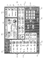
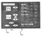
図5は、タッチスクリーン900上の主モニタ表示70を示す。主モニタ表示70は、(1)患者の極めて重要なパラメータを表す信号の表示72、(2)患者の極めて重要なパラメータそれぞれの履歴データの表示74、(3)プロポフォール注入情報および効果部位レベルの表示76、(4)ART情報の表示78、(5)あらゆるシステム助言および/またはあらゆる患者状態アラームの表示80、(6)日時、および送出システムの電力状態の表示81、ならびに(7)異なる患者呼吸状態(吸気、呼気、無呼吸、完全な口呼吸)中に送出される異なるレベルのO2流量を伝える補充酸素投与状態(図4参照)のアイコン表示83、のうちのいずれかまたはすべてを提供することができる。主モニタ表示70は、システム開始後はいつでもユーザ3への表示に利用することができる。他の表示も、主モニタ表示70に重なるポップアップウィンドウとしてタッチスクリーン900上に提示することができる。
【0044】
主モニタ表示70は、対応するパラメータデータボックスに表示される、患者の極めて重要なパラメータそれぞれの現在値のデジタル表示82を含むことが可能である。これらボックスは、そこに表示される情報が常に、各種ポップアップオーバーレイウィンドウが表示されている場合であってもユーザ3への表示に利用可能なように主モニタ表示70上に配置される。パラメータデータボックスの背景色、ならびにパラメータを表す文字の色およびサイズは、離れたところからユーザ3が容易に読み取れ、UI1から物理的に離れたユーザが監視可能なように選択される。たとえば、背景は黒であり、文字は白であることができる。パラメータボックスは、ユーザ3が、極めて重要なすべてのデータを探して2箇所以上の場所に目を向ける必要なく、すべてのパラメータを容易に参照することができるように、主モニタ表示70の一部分内にグループ化することが可能である。パラメータ値は、関連する生理学的機能に従ってグループ化することができる。
【0045】
引き続き図5を参照すると、主モニタ表示70は、生理学的システム(たとえば、血流力学/心臓血管84、酸素供給86、および呼吸換気装置88)を表す有意なデータセットに編成された情報を有し、情報の組織配列またはセマンティック(semantic)が一度意味を有すると、安全データセットに格納されている正常範囲外にあるとき、アラームパラメータがコンテキストにおいて色分けされる。たとえば、BPおよびHR(血流力学/心臓血管パラメータの両方である)が非正常すなわち警告レベルである場合、コンテキストにおいて、その背景色が、異常の度合いに応じて、たとえば深刻な場合は赤色、警告レベルの場合は黄色に色分けされる。この色分けにより、ユーザ3は、生理学的システム(血流力学/心臓血管84、酸素供給86、呼吸/換気装置88、薬物レベル76、および患者反応性78)に関連する、有意にグループ化されたデータのコンテキストにおいて、警告レベルのパラメータを評価することができる。多くの臨床医は、手術、外来、および外来患者設定で異なるオフィスで作業し、一貫しないユーザインタフェースに混乱する場合がある。UI1は、異なる場所にある同じ設計の異なる機械が、あちこち移動するユーザに同じルックアンドフィールを表す。
【0046】
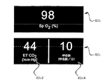
適切な装置によって感知され、プロポフォールまたは他の鎮静薬または鎮痛薬の投与、あるいは鎮静および鎮痛の送出に関連する患者の極めて重要なあらゆるパラメータは、送出システム2により使用することができ、UI1を介してユーザ3に表示することができると考えられる。以下のパラメータをユーザに表示することができる:心拍数、血圧(収縮期、平均、拡張期)、SpO2、呼吸終期CO2、および呼吸数。これらパラメータを主モニタ表示70においてどのようにグループ化することができるについての一例では、心拍数および血圧の読みは心臓血管パラメータボックス82a(図6により詳細に示す)に表示することができ、SpO2は酸素パラメータボックス82b(図7により詳細に示す)に表示され、呼吸終期CO2および呼吸数はCO2パラメータボックス82c(図7により詳細に示す)に表示される。
【0047】
また図5に示されるのは、患者モニタからの現在の信号がリアルタイムデータボックス72に表示される。これらボックスは、ECGデータ72a、SpO2モニタデータ72b、CO2モニタデータ72cを含むことができる。信号は、無彩色の背景上に有色の波形として表示することができ、周期的に更新することができる(たとえば、3Hz)。各信号は、異なる波形色を有することができる(たとえば、ECGデータ72aは赤、SpO2モニタデータ72bは緑、そしてCO2モニタデータ72cは灰色)。採用される色彩設計は、装置が使用される国に従って様々であってよい。たとえば、上記色彩設計は、米国でのガスの色の取り決めに適合している。各波形中のギャップ(すなわち、消去バー)72dが、現在ゼロ時間を示す。この消去バーは、信号が更新されると各リアルタイムデータボックス72をスクロールする。時刻マークが、リアルタイムデータボックス72のいずれかまたはすべての上または下の水平線に表示される。各信号のUI1での特定のデフォルトとして時刻スケール値が存在し、ユーザによる変更が可能である。
【0048】
各リアルタイムデータボックス72は、対応するモニタから得られた関連のパラメータ値を表示するパラメータデータボックス82に隣接して表示することができる。たとえば、ECGリアルタイム信号72aは心臓血管パラメータボックス82aに隣接して示され、SpO2リアルタイム信号72bは酸素飽和度パラメータボックス82bに隣接して表示され、CO2リアルタイム信号72cは呼吸パラメータボックス82cに隣接して表示される。CO2信号の縦のスケールは、隣接するCO2履歴グラフ74c(後述)のスケールと位置合わせすることができる。患者モニタがオフになった場合、信号波形の代わりに、そのことについてのメッセージが対応するリアルタイムデータボックス82に表示される。ガスの較正が行われるときはいつでも、そのことについてのメッセージ(たとえば、「CALIBRATION」の文字)がシステムによってCO2リアルタイム信号ボックス72cに、またはその付近に表示され、それによって、ユーザは、CO2リアルタイム信号を見て参照しようとした時に較正が行われていることに容易に気付くことができる。
【0049】
NIBP加圧帯がパルスオキシメータのプローブと同じ腕に配置されている場合、NIBP加圧帯がサイクリングしている間、「NIBP CYCLING(NIBPサイクリング)」メッセージがSpO2リアルタイムデータボックス72b上に配置され、NIBP加圧帯が膨張している間、SpO2アラームはディセーブルされる。UI1は、パルスオキシメータのプローブおよびNIBPの加圧帯が同じ腕にある場合のみ、NIBPサイクリング中にSpO2アラームのディセーブル化が行われるように、NIBP加圧帯がパルスオキシメータのプローブと同じ腕にあることをシステムに通知する手段もユーザに提供する。
【0050】
パルスオキシメータによって各パルス毎に発せられるビープの音調または頻度(frequency)は、SpO2値に対応する。SpO2が低いほど、ビープの頻度は低い。SpO2モニタがオフになった、または稼働していないがHRがECGモニタから利用可能な場合、デフォルトまたは中性的な音調が、実際には利用できないSpO2値またはSpO2モニタが機能していることに不適切に関連付けられる恐れがあるため、各心拍毎にビープはない。
【0051】
図5は、主モニタ表示70が、特定の極めて重要なパラメータそれぞれの最近の傾向を示す履歴グラフ74を含むことができることも示す。心拍数履歴グラフ74a、パルスオキシメトリ履歴ボックス74b、およびETCO2履歴ボックス74cを表示することができる。これらパラメータの履歴値は、システム内のデフォルトに設定されユーザにより変更可能な水平の時刻スケールを有する有色中実のグラフとして表示することができる。色は、リアルタイムデータボックス72の波形に使用される色に合わせて選択することができる。特定のパラメータに関連する垂直のスケールも、システム内のデフォルトに設定され、これもユーザにより変更可能である。CO2のように履歴グラフ74のいくつかの垂直スケールは、対応するリアルタイムデータボックス72のスケールと同じであってもよい。水平および/または垂直のスケール線は、各履歴グラフ74に表示することができる。
【0052】
履歴グラフ74は、対応するパラメータデータボックス82に隣接して主モニタ表示70上に配置される、対応するリアルタイムデータボックス72に隣接して配置することができ、それによって生理学的データライン74、86、および88が作成される。各生理学的データラインは、ユーザが迅速に目を通して参照することができる、主モニタ表示70の参照が容易な単一のエリアに配置された関連情報を含む。
【0053】
生理学的データライン84、86、および88は、ユーザ3が主モニタ表示70に表示されるデータの意味を解釈するのを支援するように主モニタ表示70上に配置することができる。たとえば、ユーザが一目で、2つのラインに図表化された現在データ間に対応があるか否かを評価することができるように、心臓血管ライン84をパルスオキシメトリライン86に隣接して配置することができる。対応する生理学的データラインには一貫したタイムラインが使用される。この対応性の有無は、あるラインにおけるデータに存在するアラーム状態が現実の深刻なアラームであるか、それともアーチファクトであるかを判断する際にユーザにとって有用でありうる。パルスオキシメトリデータに基づいてアラームが存在し、オキシメトリプロット72aおよびECGプロット72bに一対一の対応がある場合、アラームは本当である可能性が高いが、一対一の対応がない場合、アラームはアーチファクトである可能性が高い。
【0054】
図5は、互いに隣接して、有用に配置された生理学的データライン84、86、および88の一例を示す。図5は、監視されるパラメータ(ART)の次に配置された治療制御(プロポフォール)の一例も示し、プロポフォール表示76がART表示78の次に配置される形をとる。
【0055】
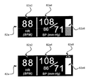
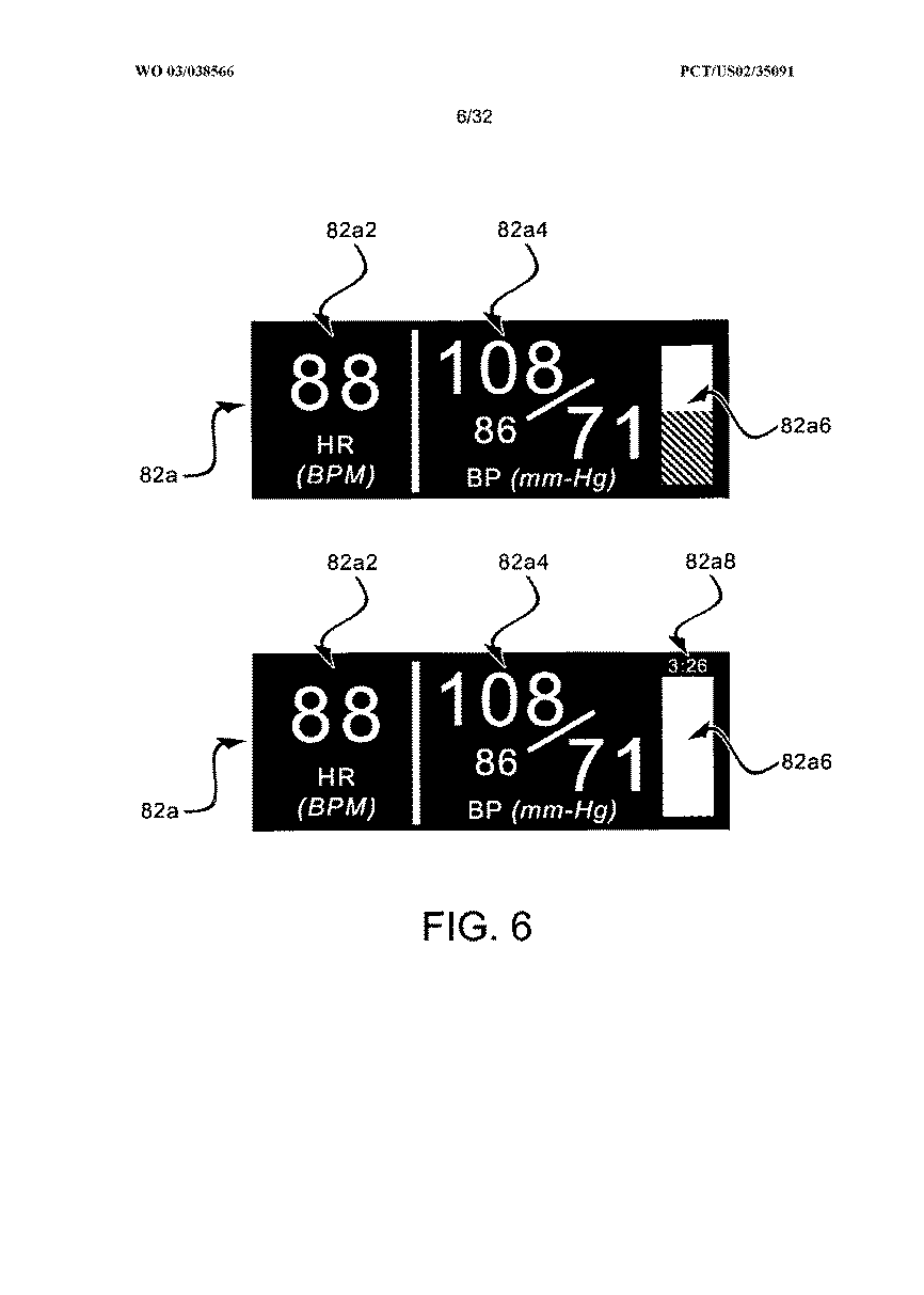
図6は、心臓血管パラメータボックス82a内の心拍数ボックス82a2に表示される心拍数を示す。心拍数は主にECGモニタから得ることができるが、ECGモニタがオフであるとき、有効なデータをECGモニタから受け取っていないとき、またはユーザがSpO2モニタを好ましい心拍数ソースとして指定したとき、SpO2モニタからも得ることができる。ECGデータがなく、SpO2モニタから入手可能な心拍数データがない場合、UI1は、心拍数ボックス82a2に心拍数パラメータの代わりに適切な指示(たとえば、「−」)を表示する。また、心臓血管パラメータボックス82aには、患者から測定された最後の収縮期血圧の読みが血圧ボックス82a4に表示される。血圧ボックスに表示しうる他のパラメータとしては、最新平均血圧、NIBP加圧帯の圧力を表示するアナログサーモメータバー82a6、および最後の加圧帯膨張から経過した時間82a8が含まれる。
【0056】
図6は、サーモメータバー82a6が表示されるUI1の実施形態では、加圧帯が血圧示度を測定しているとき、加圧帯の圧力が増すにつれてバーが上昇し、圧力が解放されるにつれて下降することを示す。血圧示度が提供されないとき(すなわち、NIBPモニタがオフになっているとき)、システムは、血圧ボックス82a4に血圧パラメータの代わりに適切な指示(たとえば、「−」)を表示する。
【0057】
図7は、酸素パラメータボックス82bのより詳細を示す。SpO2モニタがオフである、存在しない、または誤作動している場合、またはSpO2モニタから有効なデータを受け取っていない場合、システムは、酸素パラメータボックス82bにSpO2パラメータの代わりに適切な指示(たとえば、「−」)を表示する。
【0058】
図7は、CO2パラメータボックス82c内のETCO2ボックス82c2に表示される呼吸終期CO2(ETCO2)パラメータも示す。表示されるETCO2パラメータは、特定の期間(たとえば、最新の25秒)中に患者のいずれか一方のサンプリング箇所、すなわち口または鼻からのカプノメータから得られた最高値であることができる。CO2パラメータボックス内の呼吸数ボックス82c4に表示される呼吸数は、カプノメータから得られた、最新のいくつか(たとえば、4つ)の呼吸数を平均した値であることができる。カプノメータがオフである場合、またはカプノメータから有効なデータを受け取っていない場合、システムはETCO2ボックス82c2および呼吸数ボックス82c4に適切な指示(たとえば、「−」)を表示する。
【0059】
データ選択のため、カプノメータの各患者サンプリング箇所:口または鼻から集められたCO2波形値は、特定の期間(たとえば、15秒)にわたって合計することができる。このような合計後、ETCO2ボックス82c2に表示されるCO2パラメータは、特定の期間にわたってより大きな和を有する一箇所のカプノメータサンプル箇所から測定された値である。この比較は、鼻サンプルに有利なようにバイアスされる。このようなバイアスの一例では、口サンプル箇所からのデータは、鼻データの少なくとも1.5倍を超える場合にのみ表示される一方で、鼻サンプル箇所からのデータは、単に口データを越える場合に表示される。鼻カプノメータは、各鼻孔で見られる圧力信号の強度に基づいて、一方の鼻孔から他方の鼻孔にサンプリングを切り換えることができる。一方の鼻圧力センサの平均圧力値(たとえば、測定された最新の4つの値の平均)がある最小値を上回り、かつ他方のセンサの平均圧力値を少なくとも3倍上回る場合、送出システム2は、現在鼻カプノメータデータを表示している限りは、CO2波形表示用にその最初の鼻センサに切り換える。表示される(またアラームの生成に使用される)呼吸数は、波形が表示されている、口または鼻のカプノメータからの同じ入力に基づく。表示される(またアラームの生成に使用される)ETCO2値は、2つのうちの大きいほうになる。
【0060】
ガス較正が行われるときはいつでも、ユーザが、ETCO2あるいは呼吸数のいずれかのパラメータを見て参照しようとした時に較正が行われていることに容易に気付くことができるように、そのことについてのメッセージ(例えば、「CALIBRATION」という文字)が、ETCO2および/または呼吸数ボックスに、またはその付近にシステムによって表示される。したがって、メッセージは、ユーザが自然にカプノメータからの現在データを探すところに配置され、較正期間中、カプノメータからのデータがないのは、深刻な生理学的異常に起因するものではなく較正プロセスに起因するものであるという瞬間的かつ明確な指示を提供する。
【0061】
図8は、ユーザが変更した非デフォルトアラーム設定を表示するパラメータデータボックス82cの一例を示す。デフォルトアラーム設定がユーザによって変更された(後述)ときはいつでも、そのパラメータの新しいアラーム設定が、そのパラメータのデータボックス内のパラメータに隣接して表示され、それにより、ユーザは、システムの基本的なアラーム機能がそれぞれのデフォルト設定から変更されたか否かを一見して判断することができる。この特徴は、複雑な医療システムに複数人のユーザが同時に存在する場合に特に重要である。アラーム限度値はまた、ユーザがアラーム限度をアラーム設定表示から表示するように選択するときはいつでも(後述)、表示することができる。パラメータがアラーム状態にない場合、注意アラーム90の新しい非デフォルト値は注意アラーム色(たとえば、黄色)で表示することができ、警告アラーム92の新しい非デフォルト値は警告アラーム色(たとえば、赤色)で表示することができる。
【0062】
図9に示すように、パラメータがアラーム状態にあり、パラメータデータボックスの背景色がアラーム色(後述)に変更しているとき、非デフォルト値の色は、新しい背景から容易に読み取ることができる色に変更される。新しい値は、データボックスに表示されているパラメータの現在値のテキストからのオフセットであってよく、またそのテキストより小さくてもよい。
【0063】
図10は、リアルタイムデータボックス72の例をより詳細に示す。ECGリアルタイム信号72a、SpO2モニタデータ72b、およびCO2モニタデータ72cが示される。消去バー72dも示される。
【0064】
図11は、心拍数履歴グラフ74a、パルスオキシメトリ履歴ボックス74b、およびETCO2履歴ボックス74cの例を示す。
【0065】
図12はプロポフォール注入ボックス76を詳細に示す。プロポフォール注入ボックス76は、計画(projected)、現在、および履歴の計算効果部位プロポフォール濃度についての情報を示すことができる。特定期間中の履歴計算効果部位プロポフォールレベルは、現在ライン76dの一方の側にある有色グラフ76aとして示すことができ、有色計画目標効果部位グラフ76bをラインの他方の側に示すことができる。各グラフの色は同じであってもよいが、履歴データと計画データとの相違を強調するために、履歴グラフの色の輝度は異なる、たとえば、計画グラフ76bの色よりも低い。水平時間スケールはグラフ76aおよび76b両方の上あるいは下に示され、現在ライン76dの履歴側への時間は負の数として示される。効果部位レベルの履歴データおよび計画データがどの程度表示されるかについてのスケールは、システム内にデフォルトで存在するが、ユーザによる変更が可能である。効果部位における計算プロポフォール濃度の垂直スケールもデフォルトで存在するが、ユーザにより変更可能である。垂直スケールは、ユーザが新しい目標効果部位プロポフォールレベルを入力した場合に増やすこともでき、新しいレベルがグラフに確実に表示されるようにする。スケールラインは、履歴グラフおよび計画グラフの両方を横切って水平および/または垂直に表示することができる。計算効果部位プロポフォールレベルの現在値も、現在ラインの隣に、すなわち履歴グラフ76aあるいは計画グラフ76bの上にオーバーレイして表示することができる。
【0066】
プロポフォール注入ボックス76内のグラフに隣接して、プロポフォール設定ボックス76cがある。このボックスには、システムは、目標効果部位プロポフォールレベル(システムが通常モードまたはスタットモードである間)、プロポフォール設定ボックス76c内の効果部位レベルの値は単に目標レベルにすぎないことをユーザに中継して伝える「Target(目標)」という言葉または他の任意のメッセージ、プロポフォール注入の現在流量を図で示す回転流量アイコン76e、ならびに注入瓶内のプロポフォール量を示すアイコンおよび/またはグラフ76fを表示する。本発明の一実施形態では、量アイコン76fは注入瓶を模しており、瓶内に残っているプロポフォールの現在レベルの有色表現を示す。初期量の数値および現在量を決定するために、瓶アイコンの隣にスケール付きの印が示される。図12は、プロポフォール注入がアクティブであるときのプロポフォール注入ボックス76の一表示例を示している。
【0067】
図13は、プロポフォール注入ボックス76の一表示例を示す。UI1は、プロポフォール注入ボックス76を介して重要な薬物投与状態をユーザ3に明確に表示する。薬物投与の状態は、通常、減量、およびオフなどの状態を含むことができる。たとえば、減量モードの場合、適切なメッセージがプロポフォール設定ボックス76c中の目標効果部位レベルの代わりに表示され、下向きの矢印を計画グラフ76b上に表示することができる。図13は、システムが減量モードであるときのプロポフォール注入ボックス76の一表示例を示している。送出システム2がオフであり、かつプロポフォールが投与されていないときは、メッセージ「Off(オフ)」などがプロポフォール設定ボックス76cに表示されることになり、プロポフォール注入がアクティブであるときに存在する色とは異なるボックスの背景色が示される。薬物投与の履歴グラフ76aおよび現在ライン76dも示される。
【0068】
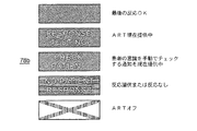
図14は、ART履歴78aセクションを含むART情報ボックス78の一表示例を示す。ART情報ボックス78は、ART状態セクション78bを含むこともできる。ART履歴セクション78a内に、UI1は、グラフのy軸に沿ったART刺激の開始と患者のARTクエリサイクルへの反応の間の時間間隔と、x軸に沿った各ART試験サイクルが開始された時間との間の関係としてプロットされる、各ARTクエリサイクルに対する患者反応のシンボルを表示することができる。自動ARTモードでは、クエリサイクルの開始から指定期間(たとえば、14秒)以内に現れた患者の反応が、ある色、たとえば緑色のシンボルとしてグラフに表示される。クエリサイクルの開始からt秒を越えて(たとえば、14.5秒または20秒)現れた、またはクエリサイクルへのまったくの反応なしを構成する患者の反応は、別の色、たとえば青色のシンボルとして表示される。t秒を越える反応時間はいずれも、または反応なしはいずれも、y軸上の時間t+1(たとえば、15秒)に表示することができる。したがって、グラフの垂直スケールに必要なのはt+1秒のみである。図14は、5つのART結果が患者クエリサイクルの開始からt秒(すなわち、14秒)越えたため、y軸に沿ってt+1秒(すなわち、15秒)に表示されている、ART履歴セクション78aの一表示例を示す。プロンプト手動ART試験に対する肯定反応は常に記録され、特定の時間tmanual(たとえば、5秒)に表示される。時間が進むにつれて、最近のART結果を表すシンボルはART履歴セクション78aの一方の側にスクロールし、所与の経過時間よりも古くなった後は表示から消えることになる。x軸スケールの範囲により、過去のART結果が表示からいつ消えることになるかが決まる。スケールは、システムにデフォルトとして存在するが、ユーザによる変更が可能である。
【0069】
図15は、ART状態セクション78bの例を示す。ART状態セクション78bは、ART試験サイクルまたは期間の持続時間中に、特定の背景色(たとえば、緑色)上に「Response Testing(反応性試験中)」または「Resposiveness Testing(反応性試験中)」という言葉を示すことができる。ART状態セクション78bは、最新のARTクエリサイクルから指定時間t秒以内であった患者反応時間に続けて、中実の特定の色(たとえば、緑色)を示す。ART状態セクション78bは、患者がクエリサイクルの開始からt秒以内に反応しない場合、または患者がクエリサイクルにまったく反応しない場合、異なる色(たとえば、青色)の背景および関連メッセージ、たとえば、「No Patient resonse(患者反応なし)」を示す。ART状態セクション78bは、クエリサイクルが現在施行されている場合もメッセージを表示し得る。ARTモードがプロンプト手動患者チェックに指定されている場合、ユーザに患者の状態を評価するよう警告するメッセージが、指定された各ART間隔で表示される。システムは、可聴トーンを再生することもでき、それによってユーザに患者を手動でチェックするよう促す。ユーザが指定時間限度、たとえば、45秒以内に患者の状態に関する情報をシステムに提供しない場合、システムは非反応患者であるものと仮定し、患者の反応を受け取らなかったことを示すメッセージを表示することができる。ユーザ3は、ARTセットアップ選好表示(後述)において手動反応性試験を促されるように選択することができる。この能力は、ユーザが適性または協力性を欠くと患者を特定した場合に使用することができる。ARTがディセーブルされている場合、適切なシンボル(たとえば、赤色の「X」)が状態セクション78b内に表示される。
【0070】
ユーザが自動反応性試験を起動すると(薬物投与を開始するとき、あるいはARTオン/オフボタン56a(図3に示す)を押下したとき)、ARTクエリサイクルが特定の間隔毎に患者に提示される。ARTクエリサイクル間の間隔は、デフォルトの期間(たとえば、3分)として存在するが、メンブレンキーパッド34上のARTセットアップボタン62を押下することによってアクセス可能なARTセットアップ選好表示(図34に示す)を介してユーザによる変更が可能である。システムは、ユーザが現在の効果部位濃度を変更した場合等の特定の状況下では、デフォルト間隔よりも短い間隔(たとえば、15秒毎)でARTクエリサイクルを自動的に提示することもできる。反応性試験は、特定の患者状態パラメータに警告または注意アラームがある(たとえば、低SpO2、低心拍数、低血圧、または低呼吸数アラーム)ときはいつでも、[いずれの間隔からも外れて]自動的に施行することもできる。ユーザ3は、ARTスタットボタン60を押下することによっていつでも自動反応性試験を手動で起動することもできる。ユーザがスタット反応性試験を要求すると、システムは、ARTクエリサイクル間の間隔に関連するタイマをリセットし、かつ/または、ユーザがスタットARTボタン60を押下したときにARTシステムがオンになっていなかった場合はARTシステムをオンにする。
【0071】
患者がn個、たとえば2つの連続した自動反応性試験サイクルに指定期間t秒以内に反応しなかったときはいつでも、システムは、特定の負のレートでのプロポフォールのゆっくりとした減量に自動的に進むことができる。次に、プロポフォール注入ボックス76に示される目標用量レベルが、減量状態の指示で置き換えられる。
【0072】
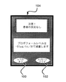
図16は、ユーザ3に短期間提示することもできる減量確認メッセージを示し、この間、ユーザは「レベルオフ(level off)」選択肢100を選択して薬物の減量を停止させ、目標効果部位レベルを現在効果部位レベルに設定させることができる。代替として、ユーザはメッセージクリア(Clear Message)選択肢102を選択して、減量確認メッセージ104を除去し、減量状態を継続させることができる。ユーザがいずれかの選択肢を選択する前に短期間が過ぎた場合、システムはメッセージを自動的にクリアする。また、患者が指定期間以内にクエリサイクルに反応しないと、患者が最初に反応しないときに、システムは可聴メッセージをユーザに向けて再生することができる。この可聴メッセージは、「Loss of Patient Response(患者反応なし)」等言葉のメッセージの形であってもよく、または患者がクエリサイクルに反応しなかったことをユーザに示唆することができる別の音であってもよい。万が一、患者が続くクエリサイクルに適時に反応するが、その後少ししてから反応しなくなった場合、可聴メッセージを再び再生することができる。ART状態セクション78b(図15)は、患者が指定期間以内にクエリサイクルに反応しないときはいつでも、反応がないことを示すメッセージを示すことができる。
【0073】
反応性試験は、患者がクエリサイクルに反応しなかった後、もう一度繰り返される。患者が2回目の試験サイクルに反応しない場合、システムは先に述べたように減量状態に入ることができる。患者反応性が回復すると、ART状態セクション78b(図15)は関連メッセージを示すことができる。ESC、レベル、または注入流量の自動減量はいずれも継続されることになるが、これは、減量確認メッセージ104においてユーザがレベルオフしない場合、またはユーザがプロポフォール用量、ESC、レベル、または注入流量を後述するように変更しない場合にである。
【0074】
ユーザがARTセットアップ選好表示においてプロンプト手動ART選択肢を選択すると、UI1は、可聴インジケータ、およびART状態セクション78bに関連メッセージを表示する反応性チェックメッセージウィンドウ106(図17)を使用して、予め定められた間隔でユーザ3を促し、ユーザ3に患者の反応性を手動で評価するように注意喚起する。ユーザ3が指定の期間以内にUIの注意喚起に応答しない場合、またはユーザ3が、患者が反応を示さないと応答する場合、UI1はメッセージを除去し、送出システム2は、上述した確認手順を用いて減量状態を起動する。失敗した手動ARTクエリの反応時間は、実際に45秒を越える場合、「15秒」における青色のシンボルとしてART履歴ボックス78a(図14)に示される。ユーザ3が、患者がまだ45秒以内で反応すると応答する場合、UI1はメッセージを除去し、送出システム2は既存の薬物体制を継続することになり、反応は、ユーザの応答時間と患者の反応時間の組み合わせが45秒未満の任意の時間でありうる場合であっても、「5」秒に対応する緑色のシンボルで示される。この方式は、合計反応時間に含められるユーザ3の応答時間が可変でありうること、および中間段階が含まれる場合、反応を得る時間がより長くかかることを考慮に入れている。図17における「はい(Yes)」ボタンの押下で示されるように、プロンプト手動クエリが指定の期間(たとえば、45秒)以内に応答されている限り、「Check patient(患者チェック)」等のテキストメッセージが、たとえば緑色の背景上に白色テキストでART状態セクション78b(図15)に表示される。
【0075】
ユーザ3は、メンブレンキーパッド34(図3)上のARTオン/オフボタン56aを押下することによってART機能をオフにすることで、反応性試験の自動施行をディセーブルすることができる。ART機能がオフであるときは、適切な指示またはメッセージがART状態セクション78b(図15)に示される。反応性試験はなお、これもまたART機能をオンにすることになるARTスタットボタン60を介して手動で開始することができる。患者が前のクエリまたはクエリサイクルに反応しないことからシステムがまだ減量状態にある間に、ユーザがART機能をオフにする場合、システムは、ユーザが薬物レベルをリセットしない限り、または薬物ESC、注入流量、またはレベルのレベルオフを選択しない限り、減量を続ける。
【0076】
図18は、ユーザ3が、鎮静および鎮痛処置中にどのアラームまたは助言が存在するかを迅速に評価する際に、目を配る必要があるのが一箇所のみであるように、患者アラームおよび/またはシステム助言を表示することができるスマートアラームボックス80の一例を示す。さらに、スマートアラームボックス80は、警告レベルのパラメータ(たとえば、SpO2)についてのラベルのみならず、完全な情報セット(たとえば、SpO2 83)も伝えるため、ユーザがアラーム状態に関連するすべての情報を導出する際に見る必要があるのは一箇所のみである。アラームまたは助言が存在しない場合、スマートアラームボックス80は特定の色(たとえば、緑色)を有する。この背景色は正常であるとみなされ、ユーザはボックスを一見してこの色を見る必要があるだけで、アラームまたは助言が存在するか否かが非常に迅速にわかる。しかし、アラームまたはシステム助言が存在する場合、スマートアラームボックス80の背景色は、正常背景色よりもコントラストが大きい、アラームおよび/または助言ブロックが目立つ異なる色(たとえば、黒色)になる。スマートアラームボックス80内のアラームおよび助言ブロックの背景は、強調のためにそれ自体色を有し(助言80cは灰色、注意80bは黄色、および警告80aは赤色)、後述する優先度でアラームボックス内に列挙される。アクティブアラームがユーザによって消音化されている場合(後述のように)、消音シンボル80dがスマートアラームボックス80の一部に現れる。アラームの消音化は、スマートアラームボックス80の残りの部分の視覚的表示、すなわちアラームおよび助言ブロックに影響しない。図18は、優先度の付いたアラームおよびシステム助言、ならびにアラーム消音シンボルを有するスマートアラームボックス80の一表示例を示す。ユーザが色盲でありうる場合に多重性を提供するために、シンボルも各種アラームの隣に提示される(助言80cには白色疑問符「?」、注意80bには黒い感嘆符を有する背景が黄色の黒い円、および警告80aには黒の感嘆符を有する白地の三角形)。
【0077】
システムは3つのレベルのアラームを提供することができる:システム助言、注意アラーム、および警告アラーム。これらアラームレベルの視覚的表示は色分けすることができる。たとえば、システム助言の表示は灰色であり、注意アラームは黄色であり、警告アラームは赤色であることができる。色分けにより、アラーム表示の意味を迅速に目で見て評価することができる。アラームまたは助言の表示は、スマートアラームボックス80の一部を占める他のアクティブアラームブロックの列内のブロックとして提示することができる。
【0078】
システム助言は、処置中の現在注意を引いている根拠となっている、送出システム2についての現在状況についてユーザ3に注意喚起させるためにユーザ3に提示される。助言は、必要でありうる(瓶の中の薬物の残量が少ない場合、またはモニタリングのリード線がほどけた場合等)が、必ずしも異常な患者状態に起因するものではないユーザの行為を示す。助言は、短く素早い音声トーンおよび/またはスマートアラームボックス80における視覚的表示によってユーザ3に提示することができる。システム助言の期間中、スマートアラームボックス80のブロックが灰色になり、特定の助言のテキスト指示がそのブロックに列挙される。アイコンまたはキャラクタ、たとえば、疑問符をテキストメッセージの隣に示すことができる。アイコンまたはキャラクタは、色色に加えて、助言とアラームとを線引きする多重手段をユーザに提供し、これは色盲のユーザに望ましいであろう。アイコンまたはキャラクタは明滅することができる。さらなる強調のため、「明滅」は「ズーム」的にシンボルのサイズを変更することができる。助言の開始後、音声トーンが規則正しい間隔で鳴り、助言の原因である問題が終わるまで、またはユーザがアラームを一時停止するまで同じ頻度で継続する。音声トーンは、周囲の状況を通して聞こえるようなボリュームで提示される。トーンの音量は調整することが可能である。
【0079】
助言の根拠となる送出システム状況は、スタートアップ診断プロセス中にユーザ3に示すことができる。助言メッセージは、特に、表5.1に列挙した状況について提示することができる。
【0080】
【表1】
注意アラームまたは警告アラームは、患者状態パラメータが注意状態あるいは警告状態に指定されたアラーム限度または範囲を超えたときにいつでもユーザ3に提示することができる。注意アラームおよび警告アラームは、連続した音声トーンまたは一連のトーンによりユーザ3に示すことができる。音声トーンは、周囲条件にわたって聞こえるような音量で提示される。トーンの音量は調整することが可能である。注意アラームまたは警告アラームの期間中、スマートアラームボックス80の背景のブロックは特定の色(たとえば、注意の場合は黄色、または警告の場合は赤色)になり、アラームに関するテキストメッセージが、背景色上で容易に見ることができるような色を有する文字(たとえば、注意アラームの場合は黄色の背景上に黒色のテキスト、または警告アラームの場合は赤色の背景上に白色のテキスト)で、そのブロックに列挙される。アイコンまたはキャラクタをテキストメッセージの隣に示すことができる。アイコンまたはキャラクタは、色以外で助言とアラームとを線引きする多重手段をユーザに提供し、これは、色盲のユーザに望ましい。アイコンまたはキャラクタは明滅することができる。さらなる強調のため、「明滅」は「ズーム」的にシンボルのサイズを変更することができる。
【0082】
注意アラームまたは警告アラームの期間中、警告レベルのパラメータを、そのパラメータの現在値とともに、主モニタ表示70(図5)上の対応するパラメータデータボックス82に表示することができる。データボックスの背景色もまたアラームの色に変わり(たとえば、注意の場合は黄色、または警告の場合は赤色)、警告レベルのパラメータの現在値が、アラーム背景色から容易に読み取ることができる色で表示される。警告レベルのパラメータの現在値は、アラーム状況が存在する限り常に更新し表示することができる。上述した図9は、注意アラームおよび警告アラームが2つのパラメータに対してアクティブであるパラメータボックス300の一例を示す。
【0083】
アラームは、警告レベルの状況が終わるまで、ユーザがいくつかのアラームについてメンブレンキーパッド34(図3)上のアラーム消音ボタン13またはアラーム一時停止11ボタンを押下することで行動するまで、またはアラーム設定がリセットされるまで連続して鳴り、表示される。消音化されたアラームは、アラームの原因となった問題が終わっていない場合、指定された消音期間後に元の状態に戻される。アラームの視覚的表示は、音声の消音化による影響を受けない。アラームがクリアされた後、アラームクリア用の音声トーンが鳴り、そのアラームメッセージの視覚的表示が、正常の色彩設計(たとえば、黒色の背景上に白色の文字)に変わる。視覚的表示は、シンボルをズーム明滅することなく短期間残る。パラメータ値は、限られた期間、アラームがクリアされたことを示す(たとえば、「OK」)メッセージで置き換えられる。アラームが表示されていないとき、スマートアラームボックス80は正常背景色(たとえば、緑色)に戻る。
【0084】
低SpO2、低心拍数、低血圧、または低呼吸の注意アラームまたは警告アラームは、新しいアラームそれぞれについて、反応性試験がイネーブルされている場合、プロンプトを表示して送出システム2に新しいARTクエリを施行するように促すことができる。低または高血圧(収縮期、拡張期、または平均動脈血圧)の注意アラームまたは警告アラームは、新しいアラームそれぞれについて、送出システム2に新しい血圧示度をもう一度測定するように促すことができる。低SpO2、あるいは低または高心拍数の注意アラームまたは警告アラームは、NIBPモニタが起動されている場合、新しいアラームそれぞれについて、送出システム2に新しい血圧示度をもう一度測定するように促すことができる。
【0085】
低SpO2または呼吸数の注意アラームは、送出システム2に、プロポフォール薬物投与またはESCを現在レベルの何分の一かに即座に低減するように促すことができる。自動薬物低減では、送出システム2は、限られた期間、薬物低減オーバーライド画面を提示し、この期間中に、ユーザ3は、適切なボタンに触れることによって送出システムの自動薬物低減行為をオーバーライドすることができる。ユーザ3がオーバーライドボタンを選択する場合、オーバーライド確認画面が表示される。確認画面からユーザ3に、以下の選択肢を起動するボタンが提示される:アラーム前のレベルでのプロポフォールの投与を再開する、またはシステムの自動プロポフォール低減を継続させるようにオーバーライドをキャンセルする。ユーザ3が投与の再開を選択する場合、送出システム2は効果部位濃度、注入流量、またはレベルをアラーム前のレベルに戻すことになり、自動低減はアラームからユーザが再開機能を選択するときまでの合間に実施されることになる。
【0086】
低SpO2注意アラームまたは低呼吸数注意アラームが、最初の自動プロポフォール低減後に特定の期間(たとえば、4分)が過ぎた後でも存在し続ける場合、システムは、上述した同じこの手順を用いてプロポフォールを再び自動的に低減することになる。システムの自動プロポフォール低減のユーザオーバーライドは、影響を受けたアラームの持続期間中、実施されたままである。すなわち、送出システム2は、同じアラーム状態に応答して、2回目はプロポフォールを低減しようとしない。
【0087】
低SpO2または呼吸数の警告アラームは、送出システム2に、薬物投与を即座に停止するように促すことができる。薬物投与の停止と同時に、送出システム2は、限られた期間、薬物停止のオーバーライド画面を提示し、この期間中に、ユーザ3は、送出システムの自動薬物停止をオーバーライドすることができる。ユーザ3がオーバーライドボタンを選択する場合、オーバーライド確認画面が表示される。確認画面からユーザ3に、以下の選択肢を起動するボタンが提示される:アラーム前のレベルでのプロポフォールの投与を再開する、またはシステムの自動プロポフォール停止処置を継続させるようにオーバーライドをキャンセルする。ユーザ3が投与の再開を選択する場合、送出システム2は効果部位濃度、注入流量、またはレベルをアラーム前のレベルに戻すことになり、自動停止はアラームからユーザ3が再開機能を選択するときまでの合間に実施されることになる。
【0088】
システムの自動プロポフォール停止のユーザオーバーライドは、影響を受けたアラームの持続期間中、実施されたままである。すなわち、送出システム2は、同じアラーム状態に応答して、2回目はプロポフォール投与を停止しようとしない。
【0089】
引き続き図18を参照すると、複数のアラームおよび/またはシステム助言が提示されるとき、送出システム2は、最高優先度の音声アラームを示す音声トーンをユーザ3に提示する。アラームおよび/または助言の視覚的表示は、それぞれの優先度順に最高から最低に、主モニタ表示70上のスマートアラームボックス80に列挙される。本発明の一実施形態では、アラームおよび助言は、以下のように優先度が付けられる:警告、注意、助言、そしてそれからクリアされたアラーム。これら各カテゴリ内では、アラームまたは助言は、それぞれの発生順によって優先度が付けられ、最も新しいものに最高の優先度が与えられる。UI1は、スマートアラームボックス80のブロック内の列中の上から下にアラームおよび助言を表示し、最高優先度のメッセージが列の最上部に表示される。多くのメッセージを表示するために、スマートアラームボックス80内に2列以上が必要な場合、最高優先度のメッセージが最も左側の列に表示される。各アラームメッセージおよび助言のシンボルまたはアイコンは、上述したように適切な色で、適切な背景色に対して提示され、アラームメッセージを含まないスマートアラームボックス80の残りの部分は、正常とは異なる色、またアラーム背景色とは異なる色(たとえば、黒)で表示される。図18は、優先度の付いたアラームおよび助言ブロックを含むスマートアラームボックス80の一表示例を示す。
【0090】
メンブレンキーパッド(図3)に設けられるアラーム消音ボタン13は、触れられると、現在アラームの音声信号を消音化させる。消音化は特定の期間行われ、アラーム消音ボタン13に続けて触れると、特定の最長消音時間限度まで延長することができる。一例として、ボタンを一度押下すると、アラームが60秒間消音化され、最初の60秒が経過する前に再び押下すると、消音時間秒読みにさらに60秒が追加され、押下する毎に、最長で合計消音時間秒読み180秒までさらに60秒が追加される。消音期間に残っている時間は表示され、それによってユーザ3はアラーム音の再発生を予想することができ、再びボタンを押下して消音期間を適時に延長することによってこのような再発生を防止することが可能である。最長消音時間限度は、ユーザ3が可聴アラームなしで作業を続けるようにするには、少なくとも時折、たとえば180秒毎に、ユーザ3に予測的な対応ステップを強制的にとらせるようにすることによってアラームの現在性を確実に認めさせる。
【0091】
消音期間中に新しいアラームが発生すると、現在の消音期間が終了し、それによって新しいアラームの音声信号および視覚信号を提示させる。このような新しいアラーム後にアラーム消音ボタン13を押下すると、新しい消音期間が開始される。現在の消音期間およびそこに表示される残り時間は、すべての現在アラームに適用される。
【0092】
図19は、日時および電力状態情報を含むバー83の一表示例を示す。日付および時刻81は、表示バー83の別の部分の中に表示してもよく、両方とも後述するシステム情報表示からユーザ3により設定することが可能である。システムのバッテリの現在充電レベルを示すアイコン81bも表示することができる。充電レベルのパーセント値81cも示すことができる。代替または追加として、残りのバッテリ充電でどれくらいシステムを実行することができるかを示す時間値を表示してもよい。これらバッテリ指示は、システムがバッテリ電力で動作しているときと、システムが外部電源で動作しているときとで別の色を有することができる。
【0093】
患者に提供されている補充O2の現在レベル(たとえば、ゼロ、低、中間、または高)も状態ボックス83に示すことができる。この情報は、水平のサーモメータバーとして図表で示すことも、またはO2流量を表す値としてテキストで示すこともできる。図19は、中間速度のO2流量(O2 flow)を示すサーモメータバーの一表示例も示している。
【0094】
図20は、患者情報表示110の一表示例を示す。患者情報表示110は、患者の体重、身長、年齢、および性別を入力するデータ入力ボックスを提供することができる。患者の氏名およびIDも入力データの一部であってもよい。体重、身長、年齢、および性別情報は、プロポフォール効果部位濃度情報を算出するためにシステムの目標制御注入アルゴリズムによって使用される。データは、適切なテキスト入力ボックスに触れ、メンブレンキーパッドまたはタッチスクリーンキーパッドを介して関連情報を入力することによってこの画面に入力することができる。体重および身長情報はkgあるいはlb単位で入力することができ、身長情報はcm、またはフィートおよびインチで入力することができる。kgボックスに情報を入力すると、計算された変換値がlbボックスに現れ、またその逆も同様である。cmボックスに情報を入力すると、計算された変換値がフィートボックスおびインチボックスに現れ、またその逆も同様である。男性/女性ボックスはトグルし、デフォルトではいずれも選択されていない。これら入力変換の利便性により、ユーザにどの値が入力されているか考えるよう求めることから、ユーザが患者情報について入力した値が一層確実になる。パラメータフィールドに表示されるデフォルトがないため、誤った値が、単にユーザが変更を怠ったデフォルト値であるというだけでシステムに使用されることが確実にないようされる。
【0095】
ユーザ3は、メンブレンキーパッド34(図3)上の患者情報(Patient Info)ボタンに触れることによって患者情報表示110にアクセスすることができ、患者情報表示110は、ポップアップウィンドウとして主モニタ表示70の上に提示することができる。所与の患者に対して鎮静および鎮痛が開始されると、患者情報表示110は変更できず、その代わりに、ユーザが鎮静および鎮痛処置中に患者情報ボタン17(図3)に触れると、現在患者のデータを報告するポップアップウィンドウ120(図21)が提示される。
【0096】
データのひどい誤入力に対するさらなるセキュリティの層として、送出システム2は、入力された体重を入力された身長、年齢、および性別と関連付けて誤入力を捕らえる体重計算図表を使用する。これは、薬物注入は入力された体重に基づいて計算される場合が多く、ユーザが患者の体重を誤入力すると深刻な結果になりうることから特に重要である。送出システム2は、これら計算図表を参照して、ユーザが入力した患者情報に対して特定のチェックを行い、入力の明らかな誤りを捕らえるために、計算図法チェックに一致しないあらゆる入力の確認をプロンプトを表示してユーザに促す。たとえば、ユーザが患者の年齢の値に2歳と入力し、同じ患者の体重の値に300パウンドを入力した場合、システムソフトウェアは、先に進む前に、入力をさらに確認するようプロンプトを表示してユーザに促す。しかし、ユーザの入力がソフトウェアによって確認されると、システムは、新しい処置の開始にあたり次のステップに進む。さらなるセキュリティ対策として、単位間の混乱による誤入力を防止するために、身長および体重の単位が、一般に使用される単位のうちの少なくとも2つの組で表示される。体重はkgあるいはパウンドで入力することができ、いずれの体重単位入力フィールドが使用されるかに関わりなく両方の単位で表示される。身長は、cmあるいはフィートおよびインチで入力することができ、いずれの身長単位入力フィールドが使用されるに関わりなく両方の単位で表示される。
【0097】
ユーザが心臓蘇生キットの不正開封防止シール(tamper-proof seal)をチェックしたことを示すチェックボックス、心臓蘇生細動除去器の存在および適切に機能することをチェックしたことを示すチェックボックス、およびユーザが追加のプロポフォール瓶を得たことを示すチェックボックスを含む特定のチェックボックスを、ユーザはシステムにより患者情報の入力が完了したとみなされる前にチェックしなければならない。細動除去器のチェックボックスは、細動除去器が心臓蘇生キットに収容されている場合、UI1から省くことができる。心臓蘇生キットのシールが破れていないことは、その心臓蘇生キットが最後に在庫補充、または証明されてから使用されていないことをユーザに示し、必要な救急用品が手元にあり、必要な場合に作動可能であるという保証をユーザおよび患者に与える。この使用前チェックシーケンスは、システムが鎮静薬または効力のある薬物を患者に投与し始める前に、前提条件が満たされているか確認するようユーザに求める。ユーザにこれらおよび他の行動をとることを思い出させることは、鎮静および鎮痛の送出の経験が少ない、または鎮静および鎮痛の送出を最近行っていなくても、患者の安全を危険に曝すことがないことを確実にする多重手段としての役割を果たす。
【0098】
再び図20を参照すると、患者データ入力中にキャンセルボタン112に触れると、トランザクションを取り消し、患者情報をそれまで格納されていたあらゆる値に戻す。OKボタン114に触れると、システムが、入力データが完全であり有効であることをチェックして確認する。患者情報が完全ではない場合、患者データエラーメッセージが表示され、完全な情報の入力をプロンプトを表示してユーザに促すことができる。身長、年齢、および体重それぞれに特定の推奨限度がシステムに提供される。ユーザにより入力された患者情報がこれら推奨限度を超える場合、患者データ警告メッセージが表示され、ユーザが患者情報表示110に戻ることによって入力を変更できるようにする。
【0099】
図21は、患者データ入力確認表示120の一表示例を示す。入力データが完全であり、送出システム2によって有効性についてチェックされると、ユーザの意図を確認するために、患者データ入力確認表示120がユーザに提示される。ユーザ3に一度入力されたデータを確認するよう求めることで、どうにかしてユーザ3に入力の誤りを見つけさせ、それによってユーザ入力ミスにより患者が被害を受ける危険性を低減する。また、患者データ入力確認表示120上、または別個の画面上で、鎮静および鎮痛の開始前に患者について考慮すべき特定の要素をユーザ3に思い出させることができる。薬物の投与を開始する前に、鎮静および鎮痛に関連するリスクに直接関係する完全な履歴および身体の検査の極めて重要な要素をユーザ3に思い出させることで、ユーザは、プロポフォールの投与を開始する前に、現在のセットアップを使用して患者を鎮静させることに問題を生じさせうる状況を捕らえることができる。
【0100】
図22は、プロポフォールパージIVセット確認表示130の一例を示す。ユーザ3がメンブレンキーパッド34(図3)上のパージIVセット(purge IV set)ボタン51を押下すると、また特定の前提条件が満たされると、プロポフォールパージIVセット確認表示130がユーザ3に提示される。これら前提条件としては、送出システム2のハウジングの所定位置に適切に装填された有効な薬物カセットがあること、およびカセットの所定位置に適切に装填された有効なプロポフォール瓶があることを含むことができる。ユーザ3がパージIVセット機能を起動しようとするときにこれら前提条件がみたされていない場合、UI1は適切なエラーメッセージを表示する。プロポフォールパージIVセット確認表示130は、パージプロセス中、患者を注入システムに接続してはならないことをユーザ3に思い出させる。送出システム2は、ユーザ3にこの注意を提示し、その後、ユーザ3がパージシーケンスを進めたいことを示した場合にのみ、パージシーケンスを進める。パージIVセットボタン51を押下すると、ユーザ3は、ただ2つの簡単な行動をとるだけでパージシーケンスを開始することができる:ハードキーを押下した後に、タッチボタンを介して確認する。次に、送出システム2は、ユーザ3によるその1つの行動後、予め選択され、経験的に決定された薬物量でIVセットを自動的にパージする。プライミングまたはパージのために薬物容器から抜き取られる薬物の量は、薬物制御モデルによって計算される、患者に投与された薬物量には加えられず、薬物残量を計算し、薬物容器の枯渇を予測するアルゴリズムの一貫として、容器から抜き出された総量に加えられる。
【0101】
送出システム2は、注入システムに接続された患者にプロポフォールを投与する前に特定の前提条件を確実に満たすようにさせる。ユーザ1が通常またはスタットプロポフォール投与機能を起動しようとすると、送出システム2は、これら前提条件が確実に満たされるようにチェックする。3つの薬物送出モードのいずれの初期起動の必要前提条件も、必要な患者データの入力および確認、心臓蘇生キットのシールが存在し、完全な状態にあることの確認、所定位置に適切に装填された有効なカセットの存在、所定位置に適切に装填された有効な瓶の存在、メインA/C電源の存在、少なくとも80%のシステムバッテリ充電の存在、機能する細動除去器の存在の確認、処置前に注入管の少なくとも一回のパージが行われたこと、管中に空気があるという指示がIVポンプによって検出されていないこと、および以下の信号:呼吸数、SpO2、および心拍数の少なくとも1つの存在、を含むことができる。前提条件のいずれかが満たされていない場合、送出システム2は投与を開始せず、満たされていない特定の条件の説明を含むプロポフォール投与エラーメッセージをユーザ3に表示する。エラートーンも再生することができる。
【0102】
図23は、通常モード投与量表示140の一例を示す。ユーザ3は、メンブレンキーパッド34(図3)のプロポフォール部分中の通常モードキー47を起動することにより、プロポフォールの目標効果部位濃度(ESC)、注入流量、またはレベルまでの一定の流量での増量を開始することができる。このキーを起動すると、通常モード投与量表示140がユーザ3に提示される。たとえば、この表示内で、選択された、または現在投与されているプロポフォールの現在ESCがタッチ入力データボックスに示される。デフォルトのESC、注入流量、または投与量0をタッチ入力データボックスに示すことができる。ユーザは、キーパッドを介して、またはいくつかの通常選択されるESCS、注入流量、または投与量を表す通常モード投与量表示上のボタンを通して新しいESC、注入流量、または投与量レベルを入力することができる。通常モード投与量表示は、計画ESCまたは投与量の図的表現142も含むことができる。薬物注入モードのアイコン表現142は、その薬物注入モードが何を実現しようと意図しているか、およびそれをどのように実現するかをユーザが容易に認識することができるように、モニタ表示70内のプロポフォール注入ボックス76に表示されるESCの計画グラフまたは投与量に類似しうる。画面上に与えられるプロポフォールの値が効果部位濃度に関連することをユーザ3に思い出せるため、またはそのことについてのユーザの認識を強化するため、効果部位を示すアイコン144(たとえば、効果部位が患者の脳にある場合、人の頭部の輪郭内に示された有色シンボル)も通常モード投与量表示140上に含めることができる。SpO2または呼吸数(後述)のパラメータ値が低い場合、あるいはARTに対する反応が遅い、またはない(上述)場合、システムがESC、注入流量、または投与量を低減する自動プロポフォール低減機能をユーザがオン/オフすることができるボックス146も投与量表示に含めることができる。ボックス146は、機能がアクティブである場合、自動低減が作動した理由をユーザに通知するのに十分なメッセージ148も含む。
【0103】
図24は、スタットモード投与量表示150の一表示例を示す。ユーザ3は、メンブレンキーパッド34のプロポフォール部分46におけるスタットモードキー49を起動することにより、可能な限りはやく目標ESCまたは投与量に到達できる速度でのプロポフォールの供給も開始することができる(この投与モードでは、目標ESCの過渡的過剰も起こり得る)。このキーが起動されると、スタットモード投与量表示150がユーザ3に提示される。この表示内で、選択された、または現在投与されている現在ESC、注入流量、またはプロポフォール投与量がタッチ入力データボックスに示される。デフォルトのESCまたは投与量0をタッチ入力データボックスに示すことができる。ユーザは、キーパッドを介して、またはいくつかの通常選択されるESCまたは投与量を表すスタットモード投与量表示150上のボタンを通して新しい濃度を入力することができる。スタットモード投与量表示150は、計画効果部位レベルの図的表現152も含むことができる。この表現152は、スタットモード薬物状態が何を実現しようと意図しているか、およびそれをどのように実現するかをユーザ3が容易に認識することができるように、プロポフォール注入ボックス76(図5)に表示される効果部位レベルの計画グラフに類似しうる。この図的表現152は、目標ESCの起こりうる過渡的過剰を表すこぶも含むことができる。さらに、ユーザ3に起こりうる過渡的過剰について注意喚起させるため、テキストメッセージボックス154もスタットモード投与量表示150に含めることができる。このような表現を使用して、スタットモードにより過渡的過剰が生じる恐れのあることをユーザ3に思い出させる。画面上に与えられるプロポフォールの値が効果部位濃度に関連することをユーザ3に思い出せるため、またはそのことについてのユーザの認識を強化するため、効果部位を示すアイコン156(たとえば、効果部位位置が患者の脳にある場合、人の頭部の輪郭内に示された有色シンボル)もスタットモード投与量表示150に含めることができる。SpO2または呼吸数(後述)のパラメータ値が低い場合、またはARTに対する反応が遅い、またはない(上述)場合、送出システム2がESCまたは投与量を低減する自動プロポフォール低減機能をユーザ3がオン/オフすることができるボックス158も投与量表示に含めることができる。このボックスは、機能がアクティブである場合、自動低減が作動した理由をユーザ3に通知するのに十分なメッセージ159も含む。しかし、スタットモードが目標ESCまたは投与量に到達しようとしている間、自動プロポフォールESCまたは投与量低減機能は送出システム2によってオフに切り換えられる。この行為が行われる前、かつこの行為が行われている間に、ユーザ3に送出システム2によるこの行為について注意喚起させるのに適したテキストメッセージボックス157が、スタットモード投与量表示150に含められる。
【0104】
図25は、自動プロポフォール低減オフ確認画面160の一表示例を示す。ユーザ3がいずれかの投与量表示から自動低減機能をディセーブルする場合、UI1は、投与量画面上にオーバーレイされる自動プロポフォール低減オフ確認画面160をユーザに提示する。ユーザ3が確認画面上のOKボタン162に触れると、送出システム2は自動プロポフォール低減のディセーブル化に進む。ディセーブルされると、自動プロポフォール低減は、ユーザ3が上述した同じ画面を移動することによって再度イネーブルするまでディセーブルされたままである。自動プロポフォール低減がディセーブルされている期間中、そのことについてのメッセージをスマートアラームボックス80(図5)の一部に表示することができ、それによって、ユーザ3は、デフォルトの自動プロポフォール低減機能が非アクティブであることに常に注意喚起される。UI1は常に、送出システムの安全アルゴリズムおよびデータセットへの有意な変更が行われたとき、ユーザ3に警告するとともに、このような変更が行われる前にユーザの確認を求める。自動低減機能がアクティブである場合であっても、送出システム2がスタット送出モードで薬物を投与しているとき、プロポフォールESCまたはレベルが上がる期間中にも同様のメッセージをユーザ3に表示することができ、これは、このようなESCまたはレベルの増大が続けられている間、送出システム2は一時的にこの機能を使用しなくなるためである。スタットモードおよび通常モードの両方において、ユーザ3がプロポフォールの新しい目標効果部位濃度を選択し、それから新しいESC目標を確認すると、UI1はESCのそれ以降の計画を更新し、それをプロポフォール注入ボックス76の計画目標効果部位グラフ76b(図12に関連して上述)に表示する。送出システム2が患者に投与するプロポフォールESCの実際の変更は、ユーザ3が各投与量モード表示上のOKボタンに触れる場合にのみ開始される。送出システム2は、ユーザが各投与量モード表示上のキャンセルボタンに触れた場合、患者に投与される現在のプロポフォールESCを変更しない。
【0105】
図26は、通常モード170およびスタットモード178の確認画面の表示例を示す。変更に先立って、入力されたプロポフォールESCは目標効果部位レベルのみであることを理解しているかユーザ3に確認させるため、中間表示170をユーザ3に提示することができる。このような実施形態が実施される場合、送出システム2は、ユーザ3が通常モード確認画面170上のOKボタン172に触れた後でのみ、現在のプロポフォールESCを変更する。これら確認画面は、通常送出モードおよびスタット送出モードそれぞれに固有であることができ、触れられると、プロポフォールレベルの効果部位制御の背後にある理論および前提をユーザ3に思い出させる別の表示を起動するボタン174を含むことができる。確認画面は、入力した値が誤りであったと認識した場合、その変更をキャンセルする機会をユーザに与えるように、ユーザが選択したESCを再表示することもできる。
【0106】
図27は、薬物注意画面180および警告画面184の表示例を示す。送出システム2は、目標にする前に、ユーザによるさらなる確認を要求しうる、特定の範囲のユーザ入力レベル、投与量、注入流量、または効果部位濃度を認識する。これら値は、システムのメモリ内に格納される安全データセットに表すことができる。たとえば、ユーザが入力したESCが、患者の年齢に釣り合った安全データセット中の特定の値(たとえば、70歳未満の患者の場合は4.0□g/cc、または70歳以上の患者の場合は3.0□g/cc)未満である場合、送出システム2はプロポフォール投与の開始プロセスに進む、すなわち、現在の投与レベルを変更するか、またはシステム開始画面(後述)を新しい処置の開始時に表示することになる。たとえば、ユーザが入力したESCがその特定の値を越えるが、第2の値(例えば、15□g/cc)未満である場合、UI1は、ユーザが入力した値が鎮静および鎮痛の場合のプロポフォール推奨値最大限度を超えるとユーザ3に注意を促す鎮静および鎮痛の薬物警告画面180をユーザ3に表示する。この画面は、入力されたESCを実現するユーザの意図を確認またはキャンセルするようユーザ3に促す。これは、注意を表すテキストに色(たとえば、黄色)の付いた背景を含むことができる。例えば、ユーザが入力したESCが第2の値を超えるが、まだ第3の値(たとえば、20□g/cc)未満である場合、システムは、ユーザが入力した値が全身麻酔のプロポフォール推奨値最大限度を越えるとユーザに警告する全身麻酔の場合の薬物警告画面184をユーザ3に表示する。この画面は、入力されたESCを実現するユーザの意図を確認またはキャンセルするようユーザ3に促す。これは、警告を表すテキストに色(たとえば、赤)の付いた背景を含むことができる。ユーザ3がこれら警告画面の1つで、ユーザが入力したレベル値を確認すると、送出システム2は、現在投与レベルを変更するか、またはUI1が新しい処置の開始時にシステム開始画面(後述)を表示する。ユーザ3が入力したESCが第3の値さえも超える場合、UI1は、プロポフォール超過エラーメッセージをユーザ3に表示し、投与量モード画面の表示に戻り、送出システム2は、ユーザ3が新しい、より低いESC値を入力するまでプロポフォールの投与の開始を許可しない。システムのこういった値のチェックおよび多重確認機能により、ユーザ3による不注意な入力が、送出システム2が患者への過量投与を引き起こすのに十分なプロポフォールレベルを投与するポイントまで気付かれずに進んでしまうリスクを大幅に低減することができる。
【0107】
適切なユーザ確認が行われると、UI1は主モニタ表示70に戻り、プロポフォール目標レベルボックス中の流量インジケータ76eおよびキーパッド34(図3)上のプロポフォールLED48が、定められたシーケンスおよび速度で動き始める、または発光し始める。ユーザ3は、上記画面を移動し、0の効果部位レベルを入力することにより、またはメンブレンキーパッド34(図3)のプロポフォール部分46内にあるプロポフォール停止ボタン53を押下することにより、いつでもプロポフォールの投与を打ち切ることができる。
【0108】
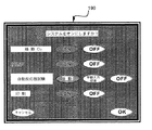
図28は、システム開始確認画面190の一例を示す。新たな患者にプロポフォールの最初の投与を開始するとき、UI1は、システムスタートアップシーケンス中の都合のよい時点でモニタおよびサブシステムをオンにすることをユーザ3に思い出させ、それによって、気を散らせる偽陽性アラームを発生させうるサブシステムの早まった起動(たとえば、加圧帯が患者に取り付けられる前のNIBP起動、または患者がハンドピースを握る前のART起動)、サブシステムの危険な起動(たとえば、呼吸に低酸素刺激を用いる患者に対する補充酸素の投与)、およびサブシステムの都合の悪い起動(たとえば、適切なときよりも先のプリント開始)を防止する。これら注意は、送出システム2が、開始中に、関連するモニタまたはサブシステムの1つが非アクティブであることを感知する場合、システム開始確認画面190の形でユーザ3に提示することができる。関連するモニタまたはサブシステムそれぞれのデフォルト設定は、ユーザがプロポフォールを患者に投与する前に、予測的に、または意識してこれらモニタまたはサブシステムをオフにすると決めなければならないように、アクティブであることができる。
【0109】
ユーザ3が、まずNIBPモニタを起動することなく、プロポフォール等の鎮静薬を投与しようとする場合、送出システム2は、プロポフォール投与の確認画面上でのユーザ3による確認後、NIBPモニタリングを自動的に開始する。
【0110】
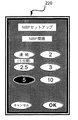
図29は、ARTセットアップ選好表示200の一例を示す。ユーザ3は、メンブレンキーパッド34(図3)上の適切なボタンを押下してポップアップウィンドウを出すことによって、特定のモニタおよびサブシステムの選好を変更することができる。たとえば、ユーザ3がARTセットアップボタン62を押下すると、ポップアップARTセットアップ選好表示200が現れ、ユーザ3がART送出モード、間隔、および言語に関連する選好を変更できるようにする。ユーザ3は、送出システム2に反応性試験を自動的に施行させるか、それとも患者の反応性を手動で評価するようユーザ3に促すかを選択することができる。ユーザ3は、間隔選好の下で、反応性クエリサイクル間に過ぎる時間量を選択することができ、言語選好の下で、送出システム2が促す、または患者に問い合わせる言語を選択することができる。
【0111】
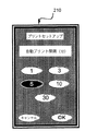
図30は、重要な患者パラメータの自動プリントアウトを送出システム2が生成する頻度をユーザ3が選択することができる、UI1によって提示可能なプリントセットアップ選好表示210の一例を示す。自動プリントは、プリントオン/オフボタン56c(図3)を介して、またはシステム開始確認画面を介して選択または選択解除することができる。
【0112】
図31は、スタットプリントアウト画面の一表示例を示す。この画面から、ユーザ3は、ボタン30を選択してテキストおよび/または数値データをプリントすることもでき、またはボタン32を選択して図表波形をプリントすることもできる。UI1のプリント機能は、さらなる時間および労力集約的な局面、すなわち、患者の生理学的パラメータ、または薬物注入ならびにこれらイベントが行われた時間等、臨床的介入の書面記録を保持することを低減することを目的としている。スタンドアロン型モニタに表示されているパラメータを読み取り、医療記録に手動で書き写すのには時間および労力がかかる。時には、介入が行われているとき、特に、正確な記録保持が最も重要である緊急時に、臨床医が忙しすぎて記録を保持することができず、事後に、誤りがちでありうる記憶に頼って何が行われたかを再構成しようと試みる必要がある。UI1は、生理学的モニタ、薬物送出システム2、およびプリンタと密に統合されているため、半自動化を介して、正確な医療記録の保持に必要な時間および労力の多くが低減される。
【0113】
図32は、NIBP測定が送出システム2によって行われる頻度をユーザ3が選択することができる、送出システム2によって提示されうるNIBPセットアップ選好表示220の一例を示す。測定の間隔は、連続(continuous)に設定して送出システム2に前の測定直後に新しい測定を自動的に行わせることができる。送出システム2は、設定された時間量後にUI表示から古くなったNIBPデータを消去することもできる。
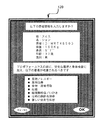
【0114】
図33は、他の表示のチャートおよびグラフ上の変更可能な各スケールのスケール範囲をユーザ3が選択することができる、送出システム2によって提示されうるスケールセットアップ選好表示230の一例を示す。スケールおよび現在データへの対応する変更を主モニタ表示70(図5)に示すことができる。各スケールは、システムソフトウェアに提供される限度内の値に変更することが可能である。ユーザ3がこれら限度外の値を選択する場合、スケール限度エラーメッセージが表示される。適正な表示データ分解能を確保するため、スケール最大値は、少なくとも、スケール最小値よりも特定数の単位分大きい必要がありうる。送出システム2は、変更を実現するようにスケールを自動的に調整することができる。この単位数は患者パラメータに応じて様々であり、システムソフトウェアに含められる。ユーザが予め設定された各パラメータの範囲を越えるスケール最小値および最大値を選択する場合、適切なエラーメッセージをユーザに表示することができる。
【0115】
図34は、可聴出力のボリューム、たとえば、患者への各ART音声提供、アラームおよび助言を表すトーンのボリューム、ならびにパルス/SpO2トーンのボリューム等をユーザ3が選択することができる、またUI1によって提供されうる音声ボリュームセットアップ表示240の一例を示す。パルス/SpO2トーンのボリュームのみ、この選好画面でゼロに設定することが可能である。
【0116】
メンブレンキーパッド34(図3)上のシステム情報(system info)ボタン43を押下すると、UI1はシステム情報表示も提供することができ、ユーザ3が、日付、時刻、システムコンソール上に提示される言語、およびコンソール表示画面の輝度制御のいずれか1つまたは複数を変更できるようにする。送出システム2は、コンソール言語に対する変更が、患者へのART提示に使用される言語と同時に行うことができるようにセットアップすることができる。
【0117】
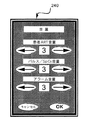
図35は、ユーザ3がメンブレンキーパッド34(図3)上のアラーム設定(alarm settings)ボタン45を押下すると、主モニタ表示70(図5)の上にポップアップウィンドウとして提示することができるアラーム設定表示250の一例を示す。ソフトウェアは各アラームにデフォルト限度を含むが、ユーザは、システム内で限度を変更するいくらかの自由を有する。ユーザ3は、対応するテキスト入力ボックスに触れ、キーパッド36図3)を使用して新しい値を入力することにより、各アラーム限度(たとえば、警告上限、注意上限、注意下限、警告下限)に新しい値を入力することができる。入力された値は、キャンセルボタン252に触れることによって取り消すことが可能であり、これにより、アラーム設定表示250が除去され、変更が行われていない主モニタ表示70を前面に戻す。デフォルトリセット(reset defaults)ボタン254に触れると、すべてのアラーム限度値がそれぞれのデフォルト値に変更される。
【0118】
図36は、アラーム限度エラーメッセージ260の一例を示す。重要な生理学的パラメータそれぞれの注意アラームおよび警告アラームの限度は、安全データセットに格納される。ユーザ3が、そのパラメータの安全データセットに格納されている範囲限度外のアラーム限度を入力する場合、アラーム限度エラーメッセージ260がユーザ3に表示され、新しいアラーム限度の入力をユーザ3に促す。
【0119】
ユーザ3が特定の生理学的パラメータのアラーム上限のテキスト入力ボックスに入力した値が、アラーム下限(警告または注意)の値未満の場合、UI1は適切なエラーメッセージをユーザ3に提示する。ユーザ3が特定の生理学的パラメータのアラーム下限のテキスト入力ボックスに入力した値が、アラーム上限(警告または注意)の値よりも大きい場合、適切なエラーメッセージがユーザ3に提示される。
【0120】
ユーザ3が警告アラーム上限に入力した値が注意アラーム上限の値未満の場合、注意アラーム上限はあるレベル、たとえば、警告アラーム上限よりも1単位分低いレベルにリセットされる。ユーザ3が注意アラーム上限に入力した値が警告アラーム上限の値よりも大きい場合、警告アラーム上限はあるレベル、たとえば、注意アラーム上限よりも1単位分上のレベルにリセットされる。
【0121】
ユーザ3が警告アラーム下限に入力した値が、対応する黄色注意アラーム下限に入力した値よりも大きい場合、黄色注意アラーム下限はあるレベル、たとえば、赤色警告アラーム下限の1単位分上のレベルにリセットされる。黄色注意アラーム下限に入力された値が、赤色警告アラーム下限の値未満である場合、赤色警告アラーム下限はあるレベル、たとえば、黄色注意アラーム下限の1単位分下のレベルにリセットされる。
【0122】
現在のアラーム限度を主モニタ表示70上に表示するか否かの選択肢をユーザ3に与えることができる。アラーム限度を表示するボタンをアラーム設定表示250(図35)に表示することができる。このボタンがオンに切り換えられているとき、最も警告レベルのパラメータのアラーム限度が、図5に関連して上述した主モニタ表示70上のそれぞれのパラメータデータボックス82に表示される。
【0123】
可聴アラーム信号のボリュームも、アップおよびダウンのボリューム調整ボタンを介してアラーム設定表示250から制御することが可能である。アラームボリュームは、ダウンボリューム調整ボタンを使用することでゼロまで下がらないようにすることができる。ユーザ3がアラームボリューム調整を変更すると、新しいボリュームで短い音を再生することによって新しいボリュームレベルがユーザ3に提示される。
【0124】
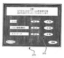
図37は、メンブレンキーパッド34(図3)上のアラーム一時停止ボタン11を押下することによって、主モニタ表示70(図5)の上に持ってくることができるポップアップウィンドウであることができるアラーム一時停止確認表示270の一例を示す。特定の患者モニタに関連するパラメータアラームおよび助言は、患者信号が検出されない期間中、システムにより一時停止するよう設定することができる。ユーザ3は、アラーム一時停止確認表示270上の対応するタッチボタンにより、またはアラーム一時停止ボタン11を押下した後に、一時停止可能な各アラーム毎にこの選択肢を選択することができる。モニタが一時停止機能によってディセーブルされた後、患者信号が関連するパラメータセンタで検出された場合、そのパラメータのアラームを鳴らすことができ、またそのモニタに関連する助言を自動的に再起動することができる。ユーザ3は、アラーム一時停止確認表示270上の対応するアクティブボタン272に触れることによってアラームおよび助言を手動で再起動することもできる。
【0125】
ECG信号が利用可能ではない場合、ユーザに表示される心拍数示度(ひいては心拍数アラームアルゴリズムへの入力)のソースは、ECGモニタから、利用可能であればパルスオキシメータに切り換えられる。同様に、パルスオキシメータ信号が利用可能ではない場合、心拍数示度(およびアラーム入力)のソースは、利用可能であればECGモニタに切り替えられる。モニタ、たとえばNIBPモニタ、CO2モニタ、SpO2モニタ、およびECGモニタが一時停止中である、機能していない、オフになっている、または存在しないことにより利用することができないいずれのパラメータにも、示度なしの指示(たとえば、「−−−」)が、主モニタ表示70(図5)上の関連するパラメータボックス82に示される。一時停止である、機能していない、オフになっている、または存在しないモニタから導き出されるパラメータの表示を除去することで、もし表示されているならば、古いパラメータを、患者の現在の生理学的状態を示す最近のデータとして誤って解釈してしまい、ユーザが、対応するモニタがオンになっており、NIBPモニタに関して先に述べたように機能していると思い込んでしまうことを防止する。しかし、一時停止中のモニタからのデータがないことを履歴ボックスに引き続き表示して、ユーザにいつモニタが一時停止またはオフになっていたかを知らせることができる。また、装置が一時停止している場合、ラベル「SUSPENDED(一時停止)」が、主モニタ表示70上に関連するリアルタイムデータボックス72があればそこに表示される。
【0126】
送出システム2のスタートアッププロセスの一貫として、ユーザ3に案内画面、次に患者情報表示、次に患者情報確認表示、そして最後に主モニタ表示70(図5)を提示することができる。システムスタートアップシーケンス後、表示画面の選択はユーザの自由である。
【0127】
ユーザ3は、メンブレンキーパッド34(図3)上の新規ケースボタン15を押下することによって新しい処置を開始することができる。送出システム2が、処置においてプロポフォールを開始した後いつでも、新しいカセットを検出した場合、UI1は、カセットの使用が6時間未満であれば、新しいケースを開始する前に、(ケース終了キー19を押下することにより)前回の処置を適切に終了することをユーザ3に思い出させる。カセットが6時間使用されている場合、UI1は、カセットを交換し、患者がなお同じ患者であるかどうか、またケースが終了してないことを確認するようユーザ3に促す。ユーザ3が処置の終了を選択したことを受けて、送出システム2は、ケース情報の最終的なプリントアウト(プリントがイネーブルされている場合)した後に、前回の患者のデータをすべてメモリからクリアさせ、変更可能なシステム設定をそれぞれのデフォルト値にリセットする。次に、送出システム2は、患者情報表示110(図20に関連して上述)を提示することによってシステムスタートアッププロセスを繰り返す。
【0128】
送出システム2は、送出システム2がアクティブである間、ユーザがケース終了ボタン19またはメンブレンキーパッド34(図3)上のオン/オフボタン38を押下するときはいつでもケース終了を記録する。ケース終了が記録されると、送出システム2は、ユーザにシャットダウン確認表示を提示することによってシャットダウンするユーザの意図を確認する。次に、ユーザ3は、送出システム2がプロポフォールの投与をやめ、ARTおよびNIBPの施行をやめ、患者データの最終報告書をプリントする(プリントがイネーブルされている場合)ことになるケース終了をボタンに触れて承認しなければならない。
【0129】
送出システム2は、すべてのアクティブな健康状態モニタ(ECG、パルスオキシメータ、およびカプノメータ)からデータが検出されないときもケース終了を記録する。このような場合、ユーザ3に送出システム2をシャットダウンするか、すべてのアラームをある期間一時停止し、その後、送出システム2がカセットを無効とみなす前に固定数(たとえば、5)の追加アラーム一時停止のみを許可するという選択肢をユーザ3に与えるケース終了確認表示がユーザ3に提示される。一時停止期間後もなおデータが検出されない場合、送出システム2は自動的にシャットダウンモードになる。
【0130】
瓶の合計最長使用時間量(たとえば、6時間)が、任意特定の処置において、送出システム2によって許される。この時間量が過ぎると、瓶の時間限度を越えたことを示す助言アラームが生成される。カセットの最長使用時間量が過ぎた場合も、同様の助言アラームが生成される。
【0131】
AC電力が失われた場合、システム助言(上述)がユーザ3に提供される。UI1は、残りのバッテリ電力が特定のレベル(たとえば、残りの動作6分)よりも下に下がった場合、適切なメッセージでユーザ3に注意喚起することもできる。送出システム2は、残りのバッテリ電力が特定のレベル(たとえば、残りの動作5分)よりも下に下がった場合はいつでも、患者へのプロポフォールの投与を停止し、ユーザ3に適切なメッセージを提供するようにセットアップすることも可能である。したがって、送出システム2は、回復を通して患者を安全に見るのに十分な時間量、動作し続ける。送出システム2の電子的コントローラが故障した場合、可聴アラームが鳴り、システム故障LED64が発光する(図3)。送出システム2は、故障するときには安全な状態となるようにする。すなわち、プロポフォール流量はオフであり、新しいNIBP測定は開始されず、進行中のNIBP測定はいずれも中止されてNIBP加圧帯が減圧され、補充酸素は定常流量(酸素が故障時に投与されていた場合)となる。その際、補充O2を限られた時間量、投与して、それからやめることができる。
【0132】
所与のパラメータモニタがまず患者に接続された後、そのモニタからデータなしの状態が2分を越える場合(上述したようにユーザがそのモニタを一時停止していない場合)、UI1はモニタエラー表示をユーザ3に表示するであろう。この表示から、ユーザ3は、アラームまたは助言がそれ以上そのパラメータに関して提示しないことを選択する、すなわち、患者データがモニタから検出されない限り、そのパラメータのアラームを一時停止するという選択肢を有する。そして、適切なメッセージ(たとえば、ダッシュのセット「−−−」)が、主モニタ表示70上の対応するパラメータボックスに表示され、パラメータがシステムによって監視されていないことを示すとともに、メッセージも関連するリアルタイムデータボックス72に表示される。
【図面の簡単な説明】
【0133】
【図1】本発明によるユーザインタフェースと併用する鎮静および鎮痛システムの一実施形態を表すブロック図を示す。
【図2】本発明の表示と併用可能なタッチセンシティブボタンおよびテキスト入力タッチボックスの例を示す。
【図3】本発明の一実施形態によるキーパッドの一例を示す。
【図4】本発明の一実施形態による患者の呼吸圧曲線の一例を示す。
【図5】本発明の一実施形態によるユーザインタフェースのモニタ表示の一例を示す。
【図6】本発明の一実施形態による心臓血管パラメータボックスの表示例を示す。
【図7】本発明の一実施形態による酸素パラメータボックスおよびCO2パラメータボックスの表示例を示す。
【図8】本発明の一実施形態による、ユーザが変更した非デフォルトのアラーム設定を表示するパラメータデータボックスの一表示例を示す。
【図9】本発明の一実施形態による、2つのパラメータに対する注意および警告アラームがアクティブになっているパラメータボックスの一表示例を示す。
【図10】本発明の一実施形態によるリアルタイムデータボックスの表示例を示す。
【図11】本発明の一実施形態によるパラメータ履歴ボックスの表示例を示す。
【図12】本発明の一実施形態によるプロポフォール注入ボックスの一表示例を示す。
【図13】本発明の一実施形態によるプロポフォール注入ボックスの別の表示例を示す。
【図14】本発明の一実施形態によるモニタ表示のART履歴セクションの一表示例を示す。
【図15】本発明の一実施形態によるモニタ表示のART状態セクションの表示例を示す。
【図16】本発明の一実施形態による減量確認メッセージの一表示例を示す。
【図17】本発明の一実施形態による反応性チェックメッセージの一表示例を示す。
【図18】本発明の一実施形態によるアクティブアラームおよび助言を示すスマートアラームボックスの一表示例を示す。
【図19】時刻、日付、および電力状態情報、ならびにO2流量を表すサーモメータバーを含む、モニタ表示のセクションの一表示例を示す。
【図20】本発明の一実施形態による患者情報表示の一例を示す。
【図21】本発明の一実施形態による患者データ入力確認表示の一例を示す。
【図22】本発明の一実施形態によるパージIV設定確認表示の一例を示す。
【図23】本発明の一実施形態による通常モード投与量表示の一例を示す。
【図24】本発明の一実施形態によるスタットモード投与量表示の一例を示す。
【図25】本発明の一実施形態による薬物警告画面の表示例を示す。
【図26】本発明の一実施形態による通常モード確認画面およびスタットモード確認画面の表示例を示す。
【図27】本発明の一実施形態による自動プロポフォール減量停止確認画面の一表示例を示す。
【図28】本発明の一実施形態によるシステム開始確認画面の一表示例を示す。
【図29】本発明の一実施形態によるARTセットアップ選好表示の一例を示す。
【図30】本発明の一実施形態によるプリントセットアップ選好表示の一例を示す。
【図31】本発明の一実施形態によるスタットプリントアウト画面の一表示例を示す。
【図32】本発明の一実施形態によるNIBPセットアップ選好表示の一例を示す。
【図33】本発明の一実施形態によるスケールセットアップ選好表示の一例を示す。
【図34】本発明の一実施形態による音声ボリュームセットアップ表示の一例を示す。
【図35】本発明の一実施形態によるアラーム設定表示の一例を示す。
【図36】本発明の一実施形態によるアラーム限度エラーメッセージの一表示例を示す。
【図37】本発明の一実施形態による保留アラーム確認表示の一例を示す。【Technical field】
[0001]
This application is a priority to US Patent Application No. 60 / 330,853 filed on November 1, 2001 under US Patent Act 119 (e), which is incorporated herein by reference in its entirety. Is an insistence.
[0002]
[Field of the Invention]
The present invention relates generally to the field of medical device control and the field of improving interaction within a patient-clinician-mechanical system that allows a clinician (s) to perform multiple tasks simultaneously. . More particularly, the present invention relates to user interfaces and control methods for medical devices such as sedation and analgesic delivery systems.
[0003]
[Background of the invention]
Designing a user interface (UI) for a clinician is a particularly cumbersome task because many clinicians may not have the time or patience to sit during extensive working hours. One aspect among clinicians is that in certain emergency situations the manual is not readily available or the clinician is not well trained about it, i.e. the device has recently been used to maintain skills. Since it may be necessary to operate the device when not in use, the designer of the device is unsatisfactory if it is necessary to read a manual to operate the medical device. Many medical devices lack this definition of intuition and usefulness in the real world. Well-designed user interfaces that anticipate the needs of clinicians are crucial, given the lack of usefulness can affect the final outcome of clinical procedures.
[0004]
With the advent of inexpensive microprocessors, the flexibility and performance of software-programmed UIs opens up the possibility of designing UIs that implement more commands and provide users with more choices and modes of operation. It was. However, in certain existing device interfaces, these commands are hidden under many hierarchical levels of sub-menus and are not immediately or intuitively clear to the user. On the other hand, command sets may not be logically grouped from a clinical point of view in the keypad or logical menu structure, so the user gets lost when moving between multiple buttons and submenu options There is a fear. Similarly, multiple operation modes can be confusing for users who are unable to follow the currently executed operation mode. For example, a physiological monitor that is connected to an actual patient but inadvertently running in simulation mode can be confusing to the user, and the data displayed on the monitor is connected to the monitor If it is simulation data, not patient data, it is dangerous.
[0005]
Touch screen input devices include a UI that includes a virtually unlimited number of touch screen buttons or data entry boxes, as well as the ability to implement add-ons in rush software, without the need to add new hard keys or input devices. Give designers flexibility. Thus, devices controlled by touch screens tend to have a small number of associated hard keys. In the technical field of user interface design, it is necessary to carefully balance competing factors. For example, increasing reliance on touch screen keys can lead to an increased number of submenu hierarchy levels, as it is usually not allowed to display all keys on a single screen of limited size. . However, if the number of hard keys is small, the medical device will rely on touch screen keys, and if the touch screen malfunctions, the medical device will not work and the user will no longer control the operation of the system. Means that it will not be possible.
[0006]
In yet another example with existing medical devices, the separate physiological monitors may be stand-alone units that do not communicate with each other. Stand-alone monitors can be placed at different locations on different devices at different locations, so clinicians operating in multiple offices based on the surgical location can be per facility, for example, to examine the ECG You may need to see different places, and this is never a desirable situation. Given the fact that multiple physiological parameters (eg, ECG, pulse oximetry data, non-invasive blood pressure, and capnometry readings) must be monitored, even the clinician's ability to find available data is quite limited Moreover, it is impossible to analyze related information by cognitive integration on a real-time basis. In addition, using the anesthesia machine example, monitored instrument parameters (eg, O 2 And N 2 Oxygen concentration set by the floater rotameter setting of O) is the corresponding physiological parameter being monitored, arterial oxygen saturation, SpO 2 There is a risk of physical separation from As an example, monitored SpO 2 The value is the inhaled oxygen concentration delivered (FiO 2 ) Should be interpreted in the context of Therefore, FiO 2 Settings (equipment parameters) and SpO 2 It is undesirable for the display (related physiological parameters) to be separated and, more generally, the treatment and the corresponding parameter being monitored in the medical device.
[0007]
The UI can have an important function as a window to the internal functions of the medical device in order to improve the transparency of the operation as well as provide feedback as the user's request is executed. As an example of lack of transparency, many existing patient monitoring devices continue to display intermittently acquired old data even when the monitor is turned off or the monitor is in standby mode. If the user forgets to turn on the monitor after turning it off, the user misunderstands that the UI displays current physiological data related to critical diagnostic and treatment decisions. There is a fear.
[0008]
A properly designed UI should enhance interaction within the clinician-machine-patient system. In order to reduce the user's cognitive workload or “data overload”, instead of presenting raw data, the UI is already processed and becomes meaningful information that can be understood at first glance. Should be presented, thereby providing the user with timely decision support.
[0009]
User errors can be avoided by clear and obvious control mechanisms and input devices. However, there are other failure modes in the current UI design. For example, default settings may cause minor accidents as demonstrated by infusion pumps. If the user actually mistakenly accepts a default concentration that is lower than the actual drug concentration, it leads to drug overdose and death. Confusion between units can also cause errors, particularly in situations where weight may be used to calculate drug infusion flow.
[0010]
The UI should not only reduce memory load, but also compensate for user forgetfulness, inaccurate data entry, and lack of judgment. Depending on the current UI, when there are multiple alarms, it may be necessary to identify which parameter alarm is being issued in the straight line of alarm dissonance that is sometimes frustrating, as well as in determining the highest priority alarm. Need to search environment or display. Alarms in current UI designs sometimes generate alarms without context. For example, an alarm may sound when the patient is not connected to a medical device, or when the patient is about to be removed from the device at the end of the procedure, and the alarm tells the user something that is already known. This is an excellent example of an alarm that can be a nuisance to tell.
[0011]
[Summary of Invention]
The present invention encompasses a sedation and analgesic delivery system user interface that allows clinicians with or without sedation and analgesia experience to operate the system easily and safely. This user interface shows information about the processes involved in sedation and analgesia, or information that interacts with this process, some can be context sensitive, such as a touch screen capable of displaying several different windows, etc. It consists of an interactive device and a separate keypad consisting of a number of buttons that activate or deactivate the main functions of the system, regardless of what is displayed on the touch screen. The display may be a multilayer display that facilitates achieving high data density, such as that available from Deep Video Imaging.
[0012]
The UI display is based on data from the patient monitor (eg, heart rate, blood pressure, SpO 2 , ETCO 2 And automatic responsiveness testing ("ART")) and treatment data, i.e. information related to drug and gas delivery, are both placed on a single screen and this information is grouped into meaningful cognition A user-friendly framework. For example, monitored physiological parameters that provide the basis for understanding the cardiovascular / hemodynamic system are grouped into a single chunk, group, or single line. Similarly, information is grouped together to help implement a user mental model that analyzes oxygen supply status, ventilation status, and drug effects. Data is constantly updated throughout the procedure. In situations that are useful for the realization of a mental model, current data of patient parameters is displayed as both numerical and graphical waveforms. Historical data is also presented for reference and comparison by the user and for trend detection. History data includes heart rate, SpO 2 , And EtCO 2 Provide information about the amount and rate of change so that clinicians who have come to help in an emergency or who are devoted to surgery or other procedures can quickly assess the patient's condition at a glance .
[0013]
The UI displays patient data on the touchscreen tissue array so that the user can easily compare data reported from various sources. And the user does not have to look around the room full of equipment to associate or cross-check different data. In addition, the UI also utilizes tissue arrangement and color coding of information while presenting treatment control and monitor data on the same UI. For example, the system may be based on pharmacokinetic calculations along a consistent timeline (eg, heart rate, SpO 2 , ECG, CO 2 Etc.) is integrated with the drug level display so that the user can correlate these parameters.
[0014]
The UI allows for easy management and presentation of patient status alarms and system advice. The UI display includes a dedicated portion where all current alarms and advice are displayed according to their priorities. Because the user only needs to see one central location on the screen, he does not lag behind all active alerts. The UI also provides redundant audio warnings for alarms and advice that can be muted by the user for a limited time. To ensure that the warning is not forgotten, the user is presented with the remaining time in the mute alarm, but the user must take a proactive step to prevent the audio warning from sounding. I must.
[0015]
During preparation and administration of sedation and analgesia, when the user changes a critical setting, the UI prompts the user to confirm the user's action to reduce the possibility of input errors. The user will be presented with a list of the results of the specific action requested, and the system will check that certain prerequisites for sedation and analgesia safety are met before the drug is administered to the patient. Made to remember.
[0016]
The system can be dangerous for the patient, such as entering doses of potentially toxic drugs, entering inconsistent patient data, or starting sedation and analgesia without first meeting the prerequisites When taking certain sexual actions, the user is warned via the UI and sedation and analgesia are not allowed to proceed. However, the design of the system also follows the view that “the clinician knows best”. In other words, rather than trying to anticipate all possible combinations of conditions and permutations of conditions in the software, the design cannot anticipate all possible clinical situations in advance and Given the data, we acknowledge that the clinician undertaking the patient makes better decisions than the pre-determined system algorithm.
[0017]
Time and labor intensive tasks such as performing drug titration during sedation and analgesia include clinical heuristics and drug state models that can be based on pharmacokinetic models and target controlled intravenous drug infusion, among others. Partially automated by using wisely. Only actions that are likely to have a safe effect, such as stopping drug infusion, are automated. Targeted control injection (TCI) also replaces the need for the user to calculate the desired injection flow profile over time (which is very difficult to do and cumbersome and time consuming to implement). One of the ways to improve the user interface because the user interface, in conjunction with the TCI algorithm, provides a user-friendly way of titrating drugs during sedation and analgesia and a much less time and labor intensive method It is.
[0018]
Target controlled infusion and clinical heuristics are combined in a drug state model. The drug state model is also tightly integrated into the UI of the sedation and analgesic delivery system, ART monitor, and drug delivery device, reducing the time and effort required to avoid inadvertent patient unconsciousness. .
[0019]
Some clinicians are suspicious that computer systems control the delivery of effective drugs without human supervision. The UI will develop a system design that provides the benefits of computer control through clinical heuristics, such as reducing time and labor intensive repetitive tasks such as drug titration while still responding to appropriate human supervision. to support.
[0020]
In contrast, overly conservative and safety-focused clinical heuristic algorithms have anticipated immediate pain treatment and deliberately delivered an amount of drug that would cause unconsciousness to cause unconsciousness. In some cases, it may interfere with the clinical process of treatment by preventing the user from performing certain actions. The UI has been proposed as well, possibly providing a message to the user before confirming that he really wants to do this, and allowing the clinician to override heuristics and algorithms for safety bias. Anticipate this clinical situation by explaining the outcome of the action.
[0021]
The UI also provides a constant notification of any changes made to the system settings so that all possible users of the system can be aware that certain defaults have been abandoned. In many cases, the user's knowledge about the current state of the system or the expected achievement of the system's functions is enhanced by the UI displaying multiple icons and text that indicate the same information characteristics.
[0022]
Many of the time-consuming implementations of sedation and analgesia or delivery of anesthetics and titrants are automated using clinical heuristics and drug status models programmed into the control software. The UI allows clinical heuristic algorithm and target control injection while allowing the user to override preprogrammed heuristics so as not to prevent the user from using the medical device to its full potential. Designed to support
[0023]
Detailed Description of the Invention
A user interface (UI) that can be functionally integrated into a sedation and analgesic delivery system is described herein. An example of such a sedation and analgesic delivery system is described in US patent application Ser. No. 09 / 324,759, filed Jun. 3, 1999, which is incorporated herein by reference in its entirety.
[0024]
Application 09 / 324,759 sedation and analgesia system is connected to a patient and is adapted to generate a signal reflecting at least one physiological condition of the patient and one or A drug delivery controller for delivering a plurality of drugs to a patient, a memory device storing a safety data set reflecting safe and undesirable parameters of at least one physiological condition monitored by the patient, a patient health monitor, An electronic controller interconnected between a drug delivery controller and a memory device storing a safety data set, wherein the electronic controller receives the signal and is responsive to the drug according to the safety data set. Manage application.
[0025]
FIG. 1 is a block diagram illustrating one embodiment of such a sedation and
[0026]
Various drugs, such as propofol, remifentanil, ketamine, dexamedetomidine, fentanyl, morphine, nitrous oxide, can be administered by or used in conjunction with
[0027]
Many aspects of UI1 are designed to be useful for a clinician with or without sedation and analgesia experience to easily operate the sedation and
[0028]
Another common feature of UI1 is that it is displayed to
[0029]
FIG. 2 is provided for the
[0030]
FIG. 2 also shows that the
[0031]
FIG. 3 shows a fixed
[0032]
As shown in FIG. 3, the
[0033]
Various system keys may be provided on the
[0034]
With continued reference to FIG. 3, various keys may be provided for activation of system functions associated with the alarm. Examples of such keys include, among others, alarm mute 13, alarm suspend 11, and
[0035]
ECG, SpO 2 And CO 2 A key 56 can be provided for activation of a patient health monitor, such as a monitor. A switch, such as an on / off
[0036]
An on / off toggle key 56a may also be provided for the ART function of the
[0037]
Similar on / off, stat, and setup keys may be provided for the non-invasive blood pressure (NIBP) function of the system. The stat NIBP and NIBP setup will be described in detail later. Similar on / off, stat, and setup keys can also be provided for the print function of the system. When the stat print key is activated, a stat print out screen (FIG. 31) is displayed to the user. The print setup will be described later in detail. An
[0038]
ECG, SpO 2 , CO 2 Individual on / off hard buttons for the NIBP and ART monitors, independent of the system to adapt to existing monitoring equipment, such as turning off the NIBP monitor if an invasive blood pressure monitor is already present in the cardiac catheter lab And can be turned off. The ability to turn off individual monitors when removed from the patient at the end of the case reduces the occurrence of inappropriate and frustrating alarms and eliminates inappropriate alarms while waiting for treatment to begin The baseline data can then be captured and printed before the procedure and subsequent individual monitor pauses. This feature of
[0039]
FIG. 3 shows replenishment O 2 Also shown is an on / off toggle key 56b that can be provided for the delivery system. Replenishment O 2 There can also be an associated
[0040]
FIG. 4 shows replenishment O 2 O when the sending system is activated 2 The respiratory pressure curve which shows each fixed high flow rate and fixed low flow rate is shown. Replenishment O 2 Fixed intermediate when the delivery system does not record subatmospheric pressure or positive pressure over a specified period of time (eg at least 30 seconds), ie when the patient is apnea or is breathing in his mouth O of flow rate 2 To the patient. If both the nasal and mouth capometers do not detect respiratory rate for at least 2 minutes during the intermediate flow period, replenishment 2 The delivery system is refilled O 2 Turn off sending O 2 To save money. This system is automatic refill 2 Provide delivery, O 2 Support patient oxygenation according to dosing algorithm. With this algorithm, the system determines from a comparison of values sampled in the patient's left and right nostrils (read by a nasal pressure transducer) after the capnometer first reports a respiratory rate greater than zero. Start recording the pressure fluctuations that will be made. When the system determines that it is generally below the
[0041]
By default, replenishment O 2 The dosing system is off when starting a new patient treatment.
[0042]
FIG. 5 shows an example of the
[0043]
FIG. 5 shows the
[0044]
The
[0045]
With continued reference to FIG. 5, the
[0046]
Any patient critical parameters sensed by the appropriate device and related to the administration of propofol or other sedation or analgesics, or sedation and delivery of analgesia, can be used by the
[0047]
Also shown in FIG. 5 is a real
[0048]
Each real-
[0049]
If the NIBP pressurization zone is placed on the same arm as the pulse oximeter probe, the NIBP CYCLING message will be displayed while the NIBP pressurization zone is cycling. 2 SpO is placed on the real-
[0050]
The tone or frequency of the beep emitted for each pulse by the pulse oximeter is the SpO. 2 Corresponds to the value. SpO 2 The lower the value, the lower the frequency of beeps. SpO 2 If the monitor is turned off or not running but HR is available from the ECG monitor, the default or neutral tone is not actually available SpO 2 Value or SpO 2 There is no beep for each heartbeat because it can be inappropriately associated with the functioning of the monitor.
[0051]
FIG. 5 also shows that the
[0052]
The
[0053]
Physiological data lines 84, 86, and 88 can be located on the
[0054]
FIG. 5 shows an example of physiological data lines 84, 86, and 88 that are usefully positioned adjacent to each other. FIG. 5 also shows an example of treatment control (propofol) placed next to the monitored parameter (ART), which takes the form that the
[0055]
FIG. 6 shows the heart rate displayed in the heart rate box 82a2 in the
[0056]
FIG. 6 shows that in the UI1 embodiment where the thermometer bar 82a6 is displayed, when the pressurization band is measuring the blood pressure reading, the bar rises and the pressure is released as the pressure in the pressurization band increases. It shows that it goes down. When no blood pressure reading is provided (ie, when the NIBP monitor is off), the system displays an appropriate indication (eg, “-”) in place of the blood pressure parameter in the blood pressure box 82a4.
[0057]
FIG. 7 shows more details of the
[0058]
Figure 7 shows CO 2 ETCO in
[0059]
Capnometer patient sampling points for data selection: CO collected from mouth or nose 2 The waveform values can be summed over a specific period (eg, 15 seconds). After such a total, ETCO 2 CO displayed in box 82c2 2 The parameter is a value measured from a single capnometer sample location that has a greater sum over a specified time period. This comparison is biased in favor of a nasal sample. In one example of such a bias, data from the mouth sample location is only displayed if it exceeds at least 1.5 times the nasal data, while data from the nasal sample location is simply over the mouth data. Is displayed. The nasal capnometer can switch sampling from one nostril to the other based on the strength of the pressure signal seen at each nostril. If the average pressure value of one nasal pressure sensor (eg, the average of the latest four measured values) exceeds a certain minimum value and exceeds the average pressure value of the other sensor by at least 3 times, the
[0060]
Whenever a gas calibration is performed, the user 2 Alternatively, a message about that (eg, the letter “CALIBRATION”) will be sent to the ETCO so that you can easily notice that the calibration is taking place when you try to look at any parameter of the breath rate. 2 And / or displayed by the system at or near the respiratory rate box. Thus, the message is placed where the user naturally looks for current data from the capnometer, and the absence of data from the capnometer during the calibration period is due to the calibration process, not due to serious physiological abnormalities. Provide an instant and clear indication that it is a thing.
[0061]
FIG. 8 shows an example of a
[0062]
As shown in FIG. 9, when the parameter is in the alarm state and the background color of the parameter data box is changed to an alarm color (described later), the color of the non-default value is a color that can be easily read from the new background. Changed to The new value may be an offset from the text of the current value of the parameter displayed in the data box, or may be smaller than that text.
[0063]
FIG. 10 shows an example of the real-
[0064]
FIG. 11 shows a heart
[0065]
FIG. 12 shows the
[0066]
Adjacent to the graph in the
[0067]
FIG. 13 shows a display example of the
[0068]
FIG. 14 shows a display example of an
[0069]
FIG. 15 shows an example of an
[0070]
When the user activates the auto-reactivity test (when starting drug administration or pressing the ART on / off
[0071]
Whenever a patient does not respond to n, for example, two consecutive auto-reactive test cycles, within a specified period of time t seconds, the system automatically responds to a slow loss of propofol at a specific negative rate. You can go forward. The target dose level shown in the
[0072]
FIG. 16 shows a weight loss confirmation message that can also be presented to the
[0073]
The responsiveness test is repeated once after the patient does not respond to the query cycle. If the patient does not respond to the second test cycle, the system can enter a weight loss state as described above. When patient responsiveness is restored, the
[0074]
When the user selects the Prompt Manual ART option in the ART Setup Preferences display, UI1 is pre-defined using an audible indicator and a responsiveness check message window 106 (FIG. 17) that displays related messages in the
[0075]
[0076]
FIG. 18 shows that patient alarm and / or so that
[0077]
The system can provide three levels of alarms: system advice, attention alarm, and warning alarm. These visual indications of alarm levels can be color coded. For example, the system advisory display can be gray, the caution alarm can be yellow, and the warning alarm can be red. By color coding, the meaning of the alarm display can be quickly and visually evaluated. The alarm or advisory display can be presented as a block in a row of other active alarm blocks that occupy part of the
[0078]
System advice is presented to the
[0079]
The delivery system status on which the advice is based can be shown to
[0080]
[Table 1]
An attention alarm or warning alarm can be presented to the
[0082]
During a caution alarm or warning alarm, a warning level parameter, along with the current value of that parameter, can be displayed in a corresponding
[0083]
The alarm will continue until the warning level situation is over, until the user acts by pressing the alarm
[0084]
Low SpO 2 Low heart rate, low blood pressure, or hypopnea attention or warning alarms, for each new alarm, will prompt and enforce a new ART query on
[0085]
Low SpO 2 Or a respiration rate caution alarm can prompt the
[0086]
Low SpO 2 If a caution alarm or hypopnea caution alarm continues to exist after a certain period of time (eg, 4 minutes) after the initial automatic propofol reduction, the system will automatically re-enable propofol using this same procedure described above. Will be reduced. The user override of the system's automatic propofol reduction remains in effect for the duration of the affected alarm. That is, the
[0087]
Low SpO 2 Alternatively, a breath rate warning alarm can prompt the
[0088]
The user override of the system's automatic propofol stop remains in effect for the duration of the affected alarm. That is, the
[0089]
With continued reference to FIG. 18, when multiple alarms and / or system advisories are presented, the
[0090]
When touched, the alarm
[0091]
If a new alarm occurs during the mute period, the current mute period ends, thereby causing a new alarm audio and visual signal to be presented. When the alarm
[0092]
FIG. 19 shows a display example of the
[0093]
Replenishment provided to patient O 2 The current level (eg, zero, low, middle, or high) can also be shown in the
[0094]
FIG. 20 shows a display example of the
[0095]
The
[0096]
As an additional layer of security against terrible false entry of data, the
[0097]
A check box indicating that the user has checked the tamper-proof seal of the resuscitation kit, a check box indicating that the presence of the resuscitation defibrillator has been checked and functioning properly, and the user The user must check certain checkboxes, including a checkbox indicating that they have obtained additional propofol bottles, before the system considers the patient information entry complete. The defibrillator check box can be omitted from UI1 if the defibrillator is housed in a cardiac resuscitation kit. An unbroken heart resuscitation kit seal indicates to the user that the heart resuscitation kit has not been used since it was last restocked or certified, and the necessary first aid is at hand and if necessary Guarantees that it is operational for users and patients. This pre-use check sequence asks the user to check that the prerequisites are met before the system begins to administer sedative or effective medication to the patient. Reminding users to take these and other actions does not jeopardize patient safety, even if they have little experience in sedation and analgesia delivery or have not recently performed sedation and analgesia delivery It serves as a multiplex means to ensure that.
[0098]
Referring back to FIG. 20, touching the cancel
[0099]
FIG. 21 shows a display example of the patient data
[0100]
FIG. 22 shows an example of the propofol purge IV set
[0101]
The
[0102]
FIG. 23 shows an example of the normal
[0103]
FIG. 24 shows a display example of the stat
[0104]
FIG. 25 shows a display example of the automatic propofol reduction off
[0105]
FIG. 26 shows display examples of confirmation screens in the
[0106]
FIG. 27 shows a display example of the
[0107]
Once the proper user confirmation is made, UI1 returns to the
[0108]
FIG. 28 shows an example of the system start
[0109]
When the
[0110]
FIG. 29 shows an example of an ART
[0111]
FIG. 30 shows an example of a print
[0112]
FIG. 31 shows a display example of the stat printout screen. From this screen, the
[0113]
FIG. 32 shows an example of an NIBP
[0114]
FIG. 33 illustrates an example of a scale
[0115]
FIG. 34 shows the volume of audible output, eg, the volume of tones representing each ART audio presentation to the patient, alarms and advice, and the pulse / SpO. 2 An example of an audio
[0116]
When the
[0117]
FIG. 35 shows the alarm settings that can be presented as a pop-up window on the main monitor display 70 (FIG. 5) when the
[0118]
FIG. 36 shows an example of the alarm
[0119]
If the value entered by the
[0120]
When the value input by the
[0121]
If the value entered by
[0122]
The
[0123]
The volume of the audible alarm signal can also be controlled from the
[0124]
FIG. 37 shows an alarm that can be a pop-up window that can be brought over the main monitor display 70 (FIG. 5) by pressing the
[0125]
If an ECG signal is not available, the source of the heart rate reading displayed to the user (and thus the input to the heart rate alarm algorithm) is switched from the ECG monitor to the pulse oximeter if available. Similarly, if a pulse oximeter signal is not available, the source of heart rate readings (and alarm input) is switched to an ECG monitor if available. Any parameters that are not available due to the monitor being suspended, not functioning, being turned off, or not present, such as the NIBP monitor, CO2 monitor, SpO2 monitor, and ECG monitor are indicated. A degree indication (eg, “---”) is shown in the associated
[0126]
As part of the startup process of the
[0127]
The
[0128]
The
[0129]
The
[0130]
A total maximum usage time of the bottle (eg, 6 hours) is allowed by the
[0131]
If AC power is lost, system advice (described above) is provided to
[0132]
If a given parameter monitor is first connected to the patient and there is no data from that monitor for more than 2 minutes (if the user has not paused the monitor as described above), UI1 will display a monitor error Will be displayed to the
[Brief description of the drawings]
[0133]
FIG. 1 shows a block diagram representing one embodiment of a sedation and analgesia system for use with a user interface according to the present invention.
FIG. 2 shows examples of touch sensitive buttons and text input touch boxes that can be used with the display of the present invention.
FIG. 3 shows an example of a keypad according to an embodiment of the present invention.
FIG. 4 shows an example of a patient respiratory pressure curve according to one embodiment of the present invention.
FIG. 5 shows an example of a monitor display of a user interface according to an embodiment of the present invention.
FIG. 6 shows a display example of a cardiovascular parameter box according to an embodiment of the present invention.
FIG. 7 shows an oxygen parameter box and CO according to an embodiment of the invention. 2 A display example of the parameter box is shown.
FIG. 8 shows an example display of a parameter data box displaying non-default alarm settings changed by a user according to an embodiment of the present invention.
FIG. 9 illustrates an example display of a parameter box with caution and warning alarms active for two parameters according to one embodiment of the present invention.
FIG. 10 shows a display example of a real-time data box according to an embodiment of the present invention.
FIG. 11 shows a display example of a parameter history box according to an embodiment of the present invention.
FIG. 12 shows an example display of a propofol infusion box according to one embodiment of the present invention.
FIG. 13 illustrates another display example of a propofol infusion box according to one embodiment of the present invention.
FIG. 14 shows a display example of an ART history section of a monitor display according to an embodiment of the present invention.
FIG. 15 shows a display example of an ART status section of a monitor display according to an embodiment of the present invention.
FIG. 16 shows a display example of a weight reduction confirmation message according to an embodiment of the present invention.
FIG. 17 shows a display example of a reactivity check message according to an embodiment of the present invention.
FIG. 18 illustrates an example display of a smart alarm box showing active alarms and advice according to one embodiment of the present invention.
FIG. 19: Time, date, and power status information, and O 2 Fig. 4 shows an example display of a section of the monitor display including a thermometer bar representing the flow rate.
FIG. 20 shows an example of patient information display according to an embodiment of the present invention.
FIG. 21 shows an example of a patient data input confirmation display according to an embodiment of the present invention.
FIG. 22 shows an example of a purge IV setting confirmation display according to an embodiment of the present invention.
FIG. 23 shows an example of a normal mode dose display according to one embodiment of the present invention.
FIG. 24 shows an example of a stat mode dose display according to one embodiment of the present invention.
FIG. 25 shows a display example of a drug warning screen according to an embodiment of the present invention.
FIG. 26 shows a display example of a normal mode confirmation screen and a stat mode confirmation screen according to an embodiment of the present invention.
FIG. 27 shows a display example of an automatic propofol weight loss stop confirmation screen according to an embodiment of the present invention.
FIG. 28 shows a display example of a system start confirmation screen according to an embodiment of the present invention.
FIG. 29 shows an example of an ART setup preference display according to one embodiment of the present invention.
FIG. 30 shows an example of a print setup preference display according to one embodiment of the present invention.
FIG. 31 shows a display example of a stat printout screen according to an embodiment of the present invention.
FIG. 32 shows an example of an NIBP setup preference display according to one embodiment of the present invention.
FIG. 33 shows an example of a scale setup preference display according to one embodiment of the present invention.
FIG. 34 shows an example of an audio volume setup display according to one embodiment of the present invention.
FIG. 35 shows an example of an alarm setting display according to an embodiment of the present invention.
FIG. 36 shows an example display of an alarm limit error message according to one embodiment of the present invention.
FIG. 37 shows an example of a pending alarm confirmation display according to an embodiment of the present invention.
Claims (37)
少なくとも1つの生理学的状況を反映した信号を受け取るようになっている1つまたは複数の患者健康状態モニタデバイスと、
1つまたは複数の薬物を供給する薬物送出コントローラと、
患者の監視されている少なくとも1つの生理学的状況の安全なパラメータおよび望ましくないパラメータを反映した安全データセットを格納したメモリデバイスと、
ユーザ入力を受け取り、システム情報、前記鎮静および鎮痛の施行、および前記少なくとも1つの生理学的状況を中継して伝えるユーザインタフェースサブシステムと、
前記患者健康状態モニタ、前記薬物送出コントローラ、前記安全データセットを格納したメモリデバイス、および前記ユーザインタフェースサブシステムの間に相互接続された電子的コントローラであって、少なくとも1つの生理学的状況を反映した前記信号および前記ユーザ入力を受け取り、これに応答して、前記安全データセットに従って前記薬物の適用を管理する電子的コントローラと、
を備える鎮静および鎮痛を施行するシステム。A system for sedation and analgesia,
One or more patient health monitoring devices adapted to receive a signal reflecting at least one physiological condition;
A drug delivery controller for supplying one or more drugs;
A memory device storing a safety data set reflecting safe and undesired parameters of at least one physiological condition being monitored by the patient;
A user interface subsystem that receives user input and relays system information, enforcement of the sedation and analgesia, and the at least one physiological condition;
An electronic controller interconnected between the patient health monitor, the drug delivery controller, a memory device storing the safety data set, and the user interface subsystem, reflecting at least one physiological situation An electronic controller that receives the signal and the user input and in response manages the application of the drug according to the safety data set;
A system that enforces sedation and analgesia.
表示用であり、かつ前記システム、前記鎮静および鎮痛の施行、および前記少なくとも1つの生理学的状況に関連するユーザ入力を受け取るタッチスクリーンまたは多層ディスプレイの少なくとも一方と、
前記タッチスクリーンまたは多層ディスプレイとは無関係に、前記システムと相互作用する別個のハードボタンセットと、
を備える、請求項1記載の鎮静および鎮痛を施行するシステム。The user interface subsystem is
At least one of a touch screen or a multi-layer display that is for display and receives user input related to the system, the sedation and analgesia, and the at least one physiological condition;
A separate set of hard buttons that interact with the system independently of the touchscreen or multi-layer display;
A system for performing sedation and analgesia according to claim 1.
a)1つまたは複数の薬物を供給する薬物送出コントローラを有する薬物送出装置を患者に接続するステップであって、
前記薬物送出コントローラは、前記患者への前記薬物の送出を制御する電子的コントローラに接続される、前記薬物送出装置を患者に接続するステップと、
b)1つまたは複数の患者健康状態モニタデバイスを患者に取り付けるステップであって、
前記健康状態モニタデバイスはそれぞれ、患者の少なくとも1つの生理学的状況を反映した値を生成し、前記電子的コントローラに接続される、患者健康状態モニタデバイスを患者に取り付けるステップと、
c)少なくとも1つの患者生理学的状況のパラメータを反映した安全データセットを格納したメモリデバイスにアクセスするステップと、
d)前記薬物送出装置、前記メモリデバイス、または前記電子的コントローラのユーザから入力を受け取るステップと、
e)前記安全データセットおよび前記ユーザ入力に従って前記薬物を前記患者に送出するステップと、
f)患者の前記少なくとも1つの生理学的状況に関する情報、および前記安全データセットおよび前記ユーザ入力に従って前記患者に薬物を送出するステップに関する情報を前記ユーザに中継して伝えるステップと、
を含む鎮静および鎮痛を施行する方法。A method of performing sedation and analgesia in connection with medical and surgical procedures,
a) connecting a drug delivery device having a drug delivery controller for supplying one or more drugs to a patient,
Connecting the drug delivery device to a patient, wherein the drug delivery controller is connected to an electronic controller that controls delivery of the drug to the patient;
b) attaching one or more patient health monitoring devices to the patient,
Each of said health monitoring devices generating a value reflecting at least one physiological condition of the patient and attaching to the patient a patient health monitoring device connected to said electronic controller;
c) accessing a memory device storing a safety data set reflecting at least one patient physiological condition parameter;
d) receiving input from a user of the drug delivery device, the memory device, or the electronic controller;
e) delivering the drug to the patient according to the safety data set and the user input;
f) relaying to the user information regarding the at least one physiological condition of the patient and information regarding delivering a drug to the patient according to the safety data set and the user input;
To perform sedation and analgesia.
患者の反応性、呼吸努力、および酸素供給を反映した値を生成する患者健康状態モニタデバイスを取り付けることを含む、請求項23記載の鎮静および鎮痛を施行する方法。Attaching the one or more patient health monitoring devices to a patient comprises:
24. A method of performing sedation and analgesia according to claim 23, comprising attaching a patient health monitoring device that generates values reflecting patient responsiveness, respiratory effort, and oxygen supply.
前記情報を単一スクリーンまたは多層ディスプレイに表示することを含む、請求項23記載の鎮静および鎮痛を施行する方法。Relaying to the user information regarding the at least one physiological condition of the patient, and information regarding delivering a drug to the patient according to the safety data set and the user input,
24. A method for performing sedation and analgesia according to claim 23, comprising displaying the information on a single screen or a multi-layer display.
前記ユーザが前記情報の異なる局面を関係付けるのを容易にするように前記情報を組織配列上でグループ化するステップを含む、請求項25記載の鎮静および鎮痛を施行する方法。Displaying the information on a single screen or multi-layer display comprises:
26. A method of performing sedation and analgesia according to claim 25, comprising grouping the information on a tissue array to facilitate the user to relate different aspects of the information.
前記ユーザが前記鎮静および鎮痛の安全な施行に対する前記情報の関連性を迅速に評価することができるように前記情報をグラフィカルに色分けするステップを含む、請求項25記載の鎮静および鎮痛を施行する方法。Displaying the information on a single screen or multi-layer display comprises:
26. A method for performing sedation and analgesia according to claim 25, comprising the step of graphically color-coding the information so that the user can quickly assess the relevance of the information to the sedation and safe enforcement of analgesia. .
システム状態アラームおよび助言ならびに患者状態アラームおよび助言の専用表示用に、前記スクリーンまたは多層ディスプレイの一部を分離するステップを含む、請求項25記載の鎮静および鎮痛を施行する方法。Displaying the information on a single screen or multi-layer display comprises:
26. A method for performing sedation and analgesia according to claim 25, comprising separating a portion of the screen or multi-layer display for system status alarms and advice and dedicated display of patient status alarms and advice.
前記ユーザが前記システム状態アラームおよび助言ならびに患者状態アラームおよび助言の優先度および重要度を迅速に評価することができるように、前記分離された部分と、前記システム状態アラームおよび助言ならびに患者状態アラームおよび助言との表示をグラフィカルに色分けするステップを含む、請求項28記載の鎮静および鎮痛を施行する方法。Separating a portion of the screen or multilayer display for dedicated display of the system status alarm and advice and patient status alarm and advice comprises:
So that the user can quickly evaluate the priority and importance of the system status alarm and advice and patient status alarm and advice and the system status alarm and advice and patient status alarm and 29. The method of performing sedation and analgesia according to claim 28, comprising the step of graphically color-coding the display with advice.
可聴インジケータを前記ユーザに対して再生することを含む、請求項23記載の鎮静および鎮痛を施行する方法。Relaying to the user information regarding the at least one physiological condition of the patient, and information regarding delivering a drug to the patient according to the safety data set and the user input,
24. A method for performing sedation and analgesia according to claim 23, comprising playing an audible indicator to the user.
前記ユーザ入力が、前記患者に対して有害となる可能性のある状況をもたらす、前記薬物送出装置、前記メモリデバイス、または前記電子的コントローラへの命令を構成している場合、前記ユーザに警告するステップと、
をさらに含む、請求項23記載の鎮静および鎮痛を施行する方法。Determining whether the user input constitutes an instruction to the drug delivery device, the memory device, or the electronic controller that results in a situation that may be harmful to the patient; ,
Alert the user if the user input constitutes an instruction to the drug delivery device, the memory device, or the electronic controller that results in a situation that may be harmful to the patient Steps,
The method of performing sedation and analgesia according to claim 23, further comprising:
タッチスクリーンまたは多層ディスプレイを介して前記ユーザから入力を受け取るステップと、
別個のハードキーセットを介して前記ユーザから前記薬物送出装置、前記メモリデバイス、または前記電子的コントローラの機能の起動に関する入力を受け取るステップとを含む、請求項23記載の鎮静および鎮痛を施行する方法。Receiving input from a user of the drug delivery device, the memory device, or the electronic controller;
Receiving input from the user via a touch screen or multilayer display;
24. A method of performing sedation and analgesia according to claim 23, comprising receiving input from said user regarding activation of a function of said drug delivery device, said memory device, or said electronic controller via a separate hard key set. .
前記ユーザ入力を既知のデータおよび/または体重計算図表と照らし合わせてチェックするステップをさらに含む、請求項23記載の鎮静および鎮痛を施行する方法。Receiving input from a user of the drug delivery device, the memory device, or the electronic controller;
24. The method of performing sedation and analgesia according to claim 23, further comprising the step of checking the user input against known data and / or weight calculation charts.
Applications Claiming Priority (2)
| Application Number | Priority Date | Filing Date | Title |
|---|---|---|---|
| US33085301P | 2001-11-01 | 2001-11-01 | |
| PCT/US2002/035091 WO2003038566A2 (en) | 2001-11-01 | 2002-11-01 | User interface for sedation and analgesia delivery systems and methods |
Related Child Applications (1)
| Application Number | Title | Priority Date | Filing Date |
|---|---|---|---|
| JP2010085410A Division JP5123348B2 (en) | 2001-11-01 | 2010-04-01 | System for performing sedation and analgesia and method of using the system |
Publications (2)
| Publication Number | Publication Date |
|---|---|
| JP2005507724A true JP2005507724A (en) | 2005-03-24 |
| JP4593108B2 JP4593108B2 (en) | 2010-12-08 |
Family
ID=23291586
Family Applications (2)
| Application Number | Title | Priority Date | Filing Date |
|---|---|---|---|
| JP2003540765A Expired - Fee Related JP4593108B2 (en) | 2001-11-01 | 2002-11-01 | User interface for sedation and analgesia delivery system |
| JP2010085410A Expired - Fee Related JP5123348B2 (en) | 2001-11-01 | 2010-04-01 | System for performing sedation and analgesia and method of using the system |
Family Applications After (1)
| Application Number | Title | Priority Date | Filing Date |
|---|---|---|---|
| JP2010085410A Expired - Fee Related JP5123348B2 (en) | 2001-11-01 | 2010-04-01 | System for performing sedation and analgesia and method of using the system |
Country Status (8)
| Country | Link |
|---|---|
| US (1) | US8567393B2 (en) |
| EP (1) | EP1448090A4 (en) |
| JP (2) | JP4593108B2 (en) |
| CN (1) | CN100563547C (en) |
| AU (1) | AU2002350108B2 (en) |
| CA (1) | CA2465625C (en) |
| MX (1) | MXPA04004246A (en) |
| WO (1) | WO2003038566A2 (en) |
Cited By (17)
| Publication number | Priority date | Publication date | Assignee | Title |
|---|---|---|---|---|
| JP2005535389A (en) * | 2002-08-08 | 2005-11-24 | スコット・ラボラトリーズ・インコーポレイテッド | Resuscitation kit system and method for sedation and analgesia system and pre-use protocol |
| JP2007503968A (en) * | 2003-06-11 | 2007-03-01 | カーリン テクノロジー リミテッド ライアビリティー カンパニー | Clinical evaluation and diagnostic tools for peristaltic pumps |
| JP2008099977A (en) * | 2006-10-20 | 2008-05-01 | Fukuda Denshi Co Ltd | Transfusion pump monitoring device |
| JP2008540004A (en) * | 2005-05-14 | 2008-11-20 | ベー・ブラウン・メルズンゲン・アクチエンゲゼルシャフト | Method and apparatus for controlling a plurality of infusion pumps |
| JP2010510033A (en) * | 2006-11-21 | 2010-04-02 | バクスター・インターナショナル・インコーポレイテッド | System and method for remote monitoring and / or management of infusion therapy |
| JP2010071837A (en) * | 2008-09-19 | 2010-04-02 | Yokogawa Electric Corp | Paperless recorder |
| JP2011500121A (en) * | 2007-10-11 | 2011-01-06 | リドコ グループ ピーエルシー | Improved patient monitoring |
| JP2011504119A (en) * | 2007-11-13 | 2011-02-03 | アイエムティ インフォメーション マネージメント テクノロジー アーゲー | Ventilator and / or anesthesia device |
| JP2011024678A (en) * | 2009-07-22 | 2011-02-10 | Terumo Corp | Oxygen enricher and warning method of oxygen enricher |
| JP2013039374A (en) * | 2011-08-16 | 2013-02-28 | Ethicon Endo Surgery Inc | Drug delivery system with open architectural framework |
| JP2015003262A (en) * | 2005-10-25 | 2015-01-08 | マリンクロッド エルエルシー | Power head control in power injection system |
| JP2015051227A (en) * | 2013-09-09 | 2015-03-19 | 日本光電工業株式会社 | Display device, display method, and control program for display device |
| JP2015181841A (en) * | 2014-03-25 | 2015-10-22 | フクダ電子株式会社 | Biological signal processing device and control method thereof |
| JP2017512588A (en) * | 2014-03-31 | 2017-05-25 | ガンブロ・ルンディア・エービーGambro Lundia Ab | Alarm docking for extracorporeal blood treatment |
| JP2017521147A (en) * | 2014-06-18 | 2017-08-03 | マケット・クリティカル・ケア・アーベー | Additive gas supply device |
| JP2019136127A (en) * | 2018-02-06 | 2019-08-22 | オリンパス株式会社 | Pneumoperitoneum device |
| JP2021119989A (en) * | 2019-04-12 | 2021-08-19 | パラマウントベッド株式会社 | Display device |
Families Citing this family (326)
| Publication number | Priority date | Publication date | Assignee | Title |
|---|---|---|---|---|
| CZ20023818A3 (en) | 2000-05-18 | 2003-06-18 | Alaris Meidical Systems, Inc. | System and method for management of information concerning provision of medical care |
| US9069887B2 (en) | 2000-05-18 | 2015-06-30 | Carefusion 303, Inc. | Patient-specific medication management system |
| US11087873B2 (en) | 2000-05-18 | 2021-08-10 | Carefusion 303, Inc. | Context-aware healthcare notification system |
| US7860583B2 (en) * | 2004-08-25 | 2010-12-28 | Carefusion 303, Inc. | System and method for dynamically adjusting patient therapy |
| US9427520B2 (en) | 2005-02-11 | 2016-08-30 | Carefusion 303, Inc. | Management of pending medication orders |
| US10353856B2 (en) | 2011-03-17 | 2019-07-16 | Carefusion 303, Inc. | Scalable communication system |
| US10062457B2 (en) | 2012-07-26 | 2018-08-28 | Carefusion 303, Inc. | Predictive notifications for adverse patient events |
| US20050171815A1 (en) * | 2003-12-31 | 2005-08-04 | Vanderveen Timothy W. | Centralized medication management system |
| US9741001B2 (en) | 2000-05-18 | 2017-08-22 | Carefusion 303, Inc. | Predictive medication safety |
| MXPA04008048A (en) * | 2002-02-20 | 2004-11-26 | Scott Lab Inc | Apparatuses and methods for outputting data from a sedation and analgesia system. |
| US7983759B2 (en) * | 2002-12-18 | 2011-07-19 | Cardiac Pacemakers, Inc. | Advanced patient management for reporting multiple health-related parameters |
| US6850788B2 (en) | 2002-03-25 | 2005-02-01 | Masimo Corporation | Physiological measurement communications adapter |
| FR2839170B1 (en) * | 2002-04-30 | 2004-12-17 | Patient On Line | INFORMATION MANAGEMENT SYSTEM INTEGRATED IN A PROTOCOL |
| WO2003097137A2 (en) | 2002-05-16 | 2003-11-27 | Scott Laboratories, Inc. | Drug container entry mechanisms and method |
| WO2004030723A2 (en) * | 2002-10-03 | 2004-04-15 | Scott Laboratories, Inc. | Bite block apparatus and method for use with a sedation an analgesia system |
| US7251683B1 (en) * | 2002-10-25 | 2007-07-31 | Sandeep Shah | Information handling system including arrangements for initiating an application in response to usage of cross reference between information and for initiating usage of a workflow flow chart associated with and information work |
| US7519541B2 (en) * | 2003-01-29 | 2009-04-14 | Cerner Innovation, Inc. | System and method in a computer system for managing a number of attachments associated with a patient |
| US20040150626A1 (en) * | 2003-01-30 | 2004-08-05 | Raymond Husman | Operator interface panel with control for visibility of desplayed objects |
| JP4818906B2 (en) | 2003-03-04 | 2011-11-16 | エシコン・エンド−サージェリィ・インコーポレイテッド | Patient monitoring and drug administration system and method of use thereof |
| US20040236188A1 (en) * | 2003-05-19 | 2004-11-25 | Ge Medical Systems Information | Method and apparatus for monitoring using a mathematical model |
| US8065161B2 (en) | 2003-11-13 | 2011-11-22 | Hospira, Inc. | System for maintaining drug information and communicating with medication delivery devices |
| US9123077B2 (en) | 2003-10-07 | 2015-09-01 | Hospira, Inc. | Medication management system |
| CN100401976C (en) * | 2003-10-28 | 2008-07-16 | 株式会社爱安德 | Electronic blood pressure meter |
| WO2005056087A1 (en) * | 2003-12-05 | 2005-06-23 | Cardinal Health 303, Inc. | Patient-controlled analgesia with patient monitoring system |
| WO2005057466A2 (en) * | 2003-12-05 | 2005-06-23 | Cardinal Health 303, Inc. | System and method fot network monitoring of multiple medical devices |
| US20050180583A1 (en) * | 2004-02-17 | 2005-08-18 | Bayon Paul W. | Advanced mute function |
| US8961461B2 (en) | 2004-05-27 | 2015-02-24 | Baxter International Inc. | Multi-state alarm system for a medical pump |
| US20060009734A1 (en) * | 2004-07-07 | 2006-01-12 | Martin James F | Dosage control for drug delivery system |
| US20060009733A1 (en) * | 2004-07-07 | 2006-01-12 | Martin James F | Bis closed loop anesthetic delivery |
| US20060042637A1 (en) * | 2004-08-31 | 2006-03-02 | Martin James F | Bite block assembly |
| US20060079842A1 (en) * | 2004-10-13 | 2006-04-13 | Liebel-Flarsheim Company | Powerhead control in a power injection system |
| US20060116639A1 (en) * | 2004-11-29 | 2006-06-01 | Russell Claudia J | Total patient input monitoring |
| US8069420B2 (en) * | 2004-12-29 | 2011-11-29 | Karl Storz Endoscopy-America, Inc. | System for controlling the communication of medical imaging data |
| US7836882B1 (en) | 2005-01-07 | 2010-11-23 | Vetland Medical Sales And Services Llc | Electronic anesthesia delivery apparatus |
| US7945452B2 (en) * | 2005-04-11 | 2011-05-17 | Hospira, Inc. | User interface improvements for medical devices |
| US20060258985A1 (en) * | 2005-05-11 | 2006-11-16 | Russell Claudia J | Graphical display of medication limits and delivery program |
| CN100415311C (en) * | 2005-06-30 | 2008-09-03 | 朱涛 | Intelligent pain-relieving and tranquilizing system |
| US9089713B2 (en) * | 2005-08-31 | 2015-07-28 | Michael Sasha John | Methods and systems for semi-automatic adjustment of medical monitoring and treatment |
| US8965509B2 (en) | 2005-08-31 | 2015-02-24 | Michael Sasha John | Methods and systems for semi-automatic adjustment of medical monitoring and treatment |
| US20080288023A1 (en) * | 2005-08-31 | 2008-11-20 | Michael Sasha John | Medical treatment using patient states, patient alerts, and hierarchical algorithms |
| US20070055460A1 (en) * | 2005-09-08 | 2007-03-08 | Searete Llc, A Limited Liability Corporation Of The State Of Delaware | Filtering predictive data |
| US10460080B2 (en) | 2005-09-08 | 2019-10-29 | Gearbox, Llc | Accessing predictive data |
| US10016249B2 (en) | 2005-09-08 | 2018-07-10 | Gearbox Llc | Accessing predictive data |
| US20070111789A1 (en) * | 2005-11-14 | 2007-05-17 | Van Deursen Marc | Interactive online Internet game and method of determining winning players |
| EP2468350B1 (en) | 2005-11-21 | 2015-09-09 | ACIST Medical Systems, Inc. | Medical fluid injection system |
| US8761851B2 (en) * | 2005-12-06 | 2014-06-24 | Cas Medical Systems, Inc. | Indicators for a spectrophotometric system |
| US7966678B2 (en) * | 2005-12-07 | 2011-06-28 | General Electric Company | Infant care bed with evaluation capabilities |
| US7451002B2 (en) * | 2006-01-06 | 2008-11-11 | Ge Medical Systems Global Technology Company, Llc | Automated generation of transfer functions based upon machine data |
| EP2026058A4 (en) * | 2006-06-08 | 2009-12-30 | Omron Healthcare Co Ltd | Biological component measurement device capable of accurately noninvasively measuring biological component |
| US20080010608A1 (en) * | 2006-07-05 | 2008-01-10 | Honeywell International, Inc. | Apparatus and methods for ensuring visibility of display window |
| EP2037999B1 (en) | 2006-07-07 | 2016-12-28 | Proteus Digital Health, Inc. | Smart parenteral administration system |
| JP2010507176A (en) | 2006-10-16 | 2010-03-04 | ホスピラ・インコーポレイテツド | System and method for comparing and utilizing dynamic information and configuration information from multiple device management systems |
| US11234650B2 (en) | 2006-11-20 | 2022-02-01 | St. Jude Medical Coordination Center Bvba | Measurement system |
| US20080188795A1 (en) * | 2007-02-02 | 2008-08-07 | Katz Hal H | Patient monitoring and drug delivery system and method of use |
| US20080221930A1 (en) | 2007-03-09 | 2008-09-11 | Spacelabs Medical, Inc. | Health data collection tool |
| CA2684807A1 (en) * | 2007-04-05 | 2008-10-16 | Velomedix, Inc. | Automated therapy system and method |
| US10702174B2 (en) * | 2007-06-27 | 2020-07-07 | Integra Lifesciences Corporation | Medical monitor user interface |
| WO2009009540A1 (en) | 2007-07-09 | 2009-01-15 | Velomedix, Inc. | Hypothermia devices and methods |
| EP2211974A4 (en) | 2007-10-25 | 2013-02-27 | Proteus Digital Health Inc | Fluid transfer port information system |
| US8517990B2 (en) * | 2007-12-18 | 2013-08-27 | Hospira, Inc. | User interface improvements for medical devices |
| US8317752B2 (en) * | 2007-12-18 | 2012-11-27 | Hospira, Inc. | Touch screen system and navigation and programming methods for an infusion pump |
| US20090183104A1 (en) * | 2008-01-03 | 2009-07-16 | Dotson Gerald A | Multi-mode viewer control for viewing and managing groups of statistics |
| US20090292179A1 (en) * | 2008-05-21 | 2009-11-26 | Ethicon Endo-Surgery, Inc. | Medical system having a medical unit and a display monitor |
| CN101590298B (en) * | 2008-05-27 | 2013-07-10 | 北京谊安医疗系统股份有限公司 | System and method used for respirator for real-time display of keyboard operation |
| DE102009013396B3 (en) | 2009-03-16 | 2010-08-05 | Dräger Medical AG & Co. KG | Apparatus and method for controlling the oxygen dosage of a ventilator |
| US8771204B2 (en) | 2008-12-30 | 2014-07-08 | Masimo Corporation | Acoustic sensor assembly |
| US8777895B2 (en) * | 2009-01-06 | 2014-07-15 | Hospira, Inc. | System and method for authorized medication delivery |
| KR101647048B1 (en) * | 2009-01-14 | 2016-08-09 | 삼성전자주식회사 | Method and apparatus for displaying information of living body |
| US10441710B2 (en) * | 2009-02-09 | 2019-10-15 | Baxter International Inc. | Infusion pump and method to prevent titration errors in infusion therapies |
| US10032002B2 (en) | 2009-03-04 | 2018-07-24 | Masimo Corporation | Medical monitoring system |
| JP5749658B2 (en) | 2009-03-04 | 2015-07-15 | マシモ・コーポレイション | Medical monitoring system |
| US10007758B2 (en) | 2009-03-04 | 2018-06-26 | Masimo Corporation | Medical monitoring system |
| US8211030B2 (en) * | 2009-03-26 | 2012-07-03 | The General Electric Company | NIBP target inflation pressure automation using derived SPO2 signals |
| US8271106B2 (en) | 2009-04-17 | 2012-09-18 | Hospira, Inc. | System and method for configuring a rule set for medical event management and responses |
| US20110022981A1 (en) * | 2009-07-23 | 2011-01-27 | Deepa Mahajan | Presentation of device utilization and outcome from a patient management system |
| WO2011026053A1 (en) | 2009-08-31 | 2011-03-03 | Abbott Diabetes Care Inc. | Displays for a medical device |
| US9265429B2 (en) * | 2009-09-18 | 2016-02-23 | Welch Allyn, Inc. | Physiological parameter measuring platform device supporting multiple workflows |
| CN102725015B (en) * | 2009-09-28 | 2015-02-04 | 凯利公司 | Controlling and communicatng with respiratory care devices |
| US8790268B2 (en) | 2009-10-15 | 2014-07-29 | Masimo Corporation | Bidirectional physiological information display |
| US8690799B2 (en) | 2009-10-15 | 2014-04-08 | Masimo Corporation | Acoustic respiratory monitoring sensor having multiple sensing elements |
| EP2488978B1 (en) * | 2009-10-15 | 2019-12-11 | Masimo Corporation | Physiological information display |
| US8821415B2 (en) | 2009-10-15 | 2014-09-02 | Masimo Corporation | Physiological acoustic monitoring system |
| US9604020B2 (en) | 2009-10-16 | 2017-03-28 | Spacelabs Healthcare Llc | Integrated, extendable anesthesia system |
| EP2488241A4 (en) * | 2009-10-16 | 2017-11-22 | Spacelabs Healthcare LLC | Integrated, extendable anesthesia system |
| EP2488837A4 (en) | 2009-10-16 | 2017-11-15 | Spacelabs Healthcare LLC | Light enhanced flow tube |
| US8552880B2 (en) * | 2009-12-04 | 2013-10-08 | Smiths Medical Asd, Inc. | Guided user help system for an ambulatory infusion system |
| JP5818806B2 (en) * | 2009-12-09 | 2015-11-18 | ナイキ イノベイト シーブイ | Exercise performance monitoring system using heart rate information |
| US11881307B2 (en) | 2012-05-24 | 2024-01-23 | Deka Products Limited Partnership | System, method, and apparatus for electronic patient care |
| US10453157B2 (en) | 2010-01-22 | 2019-10-22 | Deka Products Limited Partnership | System, method, and apparatus for electronic patient care |
| US11210611B2 (en) | 2011-12-21 | 2021-12-28 | Deka Products Limited Partnership | System, method, and apparatus for electronic patient care |
| US11244745B2 (en) | 2010-01-22 | 2022-02-08 | Deka Products Limited Partnership | Computer-implemented method, system, and apparatus for electronic patient care |
| US10911515B2 (en) | 2012-05-24 | 2021-02-02 | Deka Products Limited Partnership | System, method, and apparatus for electronic patient care |
| US20110313789A1 (en) | 2010-01-22 | 2011-12-22 | Deka Products Limited Partnership | Electronic patient monitoring system |
| US11164672B2 (en) | 2010-01-22 | 2021-11-02 | Deka Products Limited Partnership | System and apparatus for electronic patient care |
| CN102905612A (en) | 2010-02-01 | 2013-01-30 | 普罗秋斯数字健康公司 | Two-wrist data gathering system |
| MX2012008922A (en) | 2010-02-01 | 2012-10-05 | Proteus Digital Health Inc | Data gathering system. |
| JP2013521054A (en) | 2010-03-01 | 2013-06-10 | マシモ コーポレイション | Adaptive alarm system |
| US20110218406A1 (en) * | 2010-03-04 | 2011-09-08 | Nellcor Puritan Bennett Llc | Visual Display For Medical Monitor |
| CN102905616B (en) | 2010-03-21 | 2017-02-08 | 太空实验室健康护理有限公司 | Multi-Display Bedside Monitoring System |
| US8695591B2 (en) | 2010-05-26 | 2014-04-15 | Lloyd Verner Olson | Apparatus and method of monitoring and responding to respiratory depression |
| US20110298621A1 (en) * | 2010-06-02 | 2011-12-08 | Lokesh Shanbhag | System and method for generating alerts |
| WO2012006625A2 (en) | 2010-07-09 | 2012-01-12 | Velomedix, Inc. | Method and apparatus for pressure measurement |
| JP2013534338A (en) * | 2010-08-02 | 2013-09-02 | コーニンクレッカ フィリップス エヌ ヴェ | Method for semantic communication of device data between a source and a receiving client |
| US9047747B2 (en) | 2010-11-19 | 2015-06-02 | Spacelabs Healthcare Llc | Dual serial bus interface |
| WO2012083281A1 (en) | 2010-12-17 | 2012-06-21 | Spacelabs Heal Thcare. Llc | Sliding track and pivot mounting system for displays on anesthesia machines |
| US9629566B2 (en) | 2011-03-11 | 2017-04-25 | Spacelabs Healthcare Llc | Methods and systems to determine multi-parameter managed alarm hierarchy during patient monitoring |
| ITTO20110223A1 (en) | 2011-03-11 | 2012-09-12 | Cane Spa | ARCHITECTURE AND METHOD OF CONTROL AND PROGRAMMING OF AN ELECTROMEDICAL UNIT. |
| CN103501840B (en) * | 2011-03-24 | 2016-08-17 | 新加坡保健服务集团有限公司 | Control the method and system of non-comfort |
| US9384116B2 (en) * | 2011-05-16 | 2016-07-05 | Vmware, Inc. | Graphically representing load balance in a computing cluster |
| CA2844807C (en) | 2011-08-19 | 2022-07-26 | Hospira, Inc. | Systems and methods for a graphical interface including a graphical representation of medical data |
| GB2510513B (en) * | 2011-10-13 | 2017-12-27 | Spacelabs Healthcare Llc | Integrated, extendable anesthesia system |
| CN104066469B (en) * | 2011-10-13 | 2017-03-22 | 太空实验室健康护理有限公司 | Integrated, extendable anesthesia system |
| CA2852271A1 (en) | 2011-10-21 | 2013-04-25 | Hospira, Inc. | Medical device update system |
| US10022498B2 (en) | 2011-12-16 | 2018-07-17 | Icu Medical, Inc. | System for monitoring and delivering medication to a patient and method of using the same to minimize the risks associated with automated therapy |
| US8856668B2 (en) | 2011-12-22 | 2014-10-07 | Fresenius Medical Care Holdings, Inc. | Drug delivery devices and related systems and methods |
| JP5897928B2 (en) * | 2012-02-23 | 2016-04-06 | 日本光電工業株式会社 | Monitor device |
| AU2013239778B2 (en) | 2012-03-30 | 2017-09-28 | Icu Medical, Inc. | Air detection system and method for detecting air in a pump of an infusion system |
| JP6013002B2 (en) * | 2012-03-30 | 2016-10-25 | フクダ電子株式会社 | Biological signal display device and control method thereof |
| US9055870B2 (en) | 2012-04-05 | 2015-06-16 | Welch Allyn, Inc. | Physiological parameter measuring platform device supporting multiple workflows |
| US9235682B2 (en) | 2012-04-05 | 2016-01-12 | Welch Allyn, Inc. | Combined episodic and continuous parameter monitoring |
| USD772252S1 (en) | 2012-04-05 | 2016-11-22 | Welch Allyn, Inc. | Patient monitoring device with a graphical user interface |
| USD916713S1 (en) | 2012-04-05 | 2021-04-20 | Welch Allyn, Inc. | Display screen with graphical user interface for patient central monitoring station |
| US10226200B2 (en) | 2012-04-05 | 2019-03-12 | Welch Allyn, Inc. | User interface enhancements for physiological parameter monitoring platform devices |
| JP5927013B2 (en) | 2012-04-16 | 2016-05-25 | 日本光電工業株式会社 | Biological information monitor device |
| US11871901B2 (en) | 2012-05-20 | 2024-01-16 | Cilag Gmbh International | Method for situational awareness for surgical network or surgical network connected device capable of adjusting function based on a sensed situation or usage |
| EP3639733B1 (en) | 2012-05-30 | 2022-10-26 | ResMed Sensor Technologies Limited | Apparatus for monitoring cardio-pulmonary health |
| US10525219B2 (en) | 2012-06-26 | 2020-01-07 | Resmed Sensor Technologies Limited | Methods and apparatus for monitoring and treating respiratory insufficiency |
| USD741879S1 (en) * | 2012-07-30 | 2015-10-27 | General Electric Company | Display screen or portion thereof with graphical user interface |
| EP2879733B1 (en) | 2012-07-31 | 2019-06-05 | ICU Medical, Inc. | Patient care system for critical medications |
| JP6109507B2 (en) * | 2012-08-22 | 2017-04-05 | 国立大学法人鳥取大学 | Oxygen supply equipment |
| US10426904B2 (en) * | 2012-09-12 | 2019-10-01 | Maquet Critical Care Ab | Volume reflector status indicator for anesthesia system |
| US9955937B2 (en) | 2012-09-20 | 2018-05-01 | Masimo Corporation | Acoustic patient sensor coupler |
| US10133704B2 (en) * | 2012-11-07 | 2018-11-20 | Microsoft Technology Licensing, Llc | Dynamic layout of content in a grid based application |
| JP5677400B2 (en) * | 2012-11-08 | 2015-02-25 | 日本光電工業株式会社 | Biological information display device and biological information display system |
| EP2925404B1 (en) | 2012-11-29 | 2023-10-25 | Abbott Diabetes Care, Inc. | Devices and systems related to analyte monitoring |
| CA3190143A1 (en) * | 2012-12-21 | 2014-06-26 | Deka Products Limited Partnership | Computer-implemented method, system, and apparatus for electronic patient care |
| CN117558430A (en) * | 2012-12-21 | 2024-02-13 | 德卡产品有限公司 | System, method and apparatus for transmitting data |
| US10430554B2 (en) | 2013-05-23 | 2019-10-01 | Carefusion 303, Inc. | Medication preparation queue |
| US11182728B2 (en) | 2013-01-30 | 2021-11-23 | Carefusion 303, Inc. | Medication workflow management |
| AU2014225658B2 (en) | 2013-03-06 | 2018-05-31 | Icu Medical, Inc. | Medical device communication method |
| US9977413B2 (en) | 2013-03-11 | 2018-05-22 | Honeywell International Inc. | Apparatus and method for managing open windows in a graphical display for a representation of a process system |
| BR112015019758B1 (en) | 2013-03-13 | 2022-07-05 | Carefusion 303, Inc | SYSTEM AND METHOD FOR USE WITH MEDICAL DEVICE TO REDUCE MEDICATION ERRORS AND MACHINE-READABLE STORAGE MEDIA |
| EP4195119A1 (en) | 2013-03-13 | 2023-06-14 | Carefusion 303 Inc. | Predictive medication safety |
| CN104069576A (en) * | 2013-03-29 | 2014-10-01 | 北京谊安医疗系统股份有限公司 | Implementation method and device of anesthesia machine electronic flowmeter display module |
| CN105074768A (en) * | 2013-04-01 | 2015-11-18 | 泰尔茂株式会社 | Medical-information management device, medical-information management system, and medical-information management method |
| WO2014178730A2 (en) * | 2013-04-30 | 2014-11-06 | Iac Ip Limited | Anaesthetic machine |
| AU2014268355B2 (en) | 2013-05-24 | 2018-06-14 | Icu Medical, Inc. | Multi-sensor infusion system for detecting air or an occlusion in the infusion system |
| ES2838450T3 (en) | 2013-05-29 | 2021-07-02 | Icu Medical Inc | Infusion set that uses one or more sensors and additional information to make an air determination relative to the infusion set |
| EP3003442B1 (en) | 2013-05-29 | 2020-12-30 | ICU Medical, Inc. | Infusion system and method of use which prevents over-saturation of an analog-to-digital converter |
| US10987026B2 (en) | 2013-05-30 | 2021-04-27 | Spacelabs Healthcare Llc | Capnography module with automatic switching between mainstream and sidestream monitoring |
| US10777313B2 (en) | 2013-06-13 | 2020-09-15 | Carefusion 303, Inc. | Analytics regarding ventilated patients |
| US11183287B2 (en) | 2013-06-13 | 2021-11-23 | Carefusion 303, Inc. | Analytics regarding patient care |
| WO2015002550A1 (en) * | 2013-07-03 | 2015-01-08 | Fisher & Paykel Healthcare Limited | Breathing assistance apparatus user interface |
| WO2015000979A1 (en) * | 2013-07-05 | 2015-01-08 | Koninklijke Philips N.V. | Patient user interface for controlling a patient display |
| JP6242106B2 (en) * | 2013-07-31 | 2017-12-06 | フクダ電子株式会社 | Biological information monitor and display method in biological information monitor |
| US20150066531A1 (en) | 2013-08-30 | 2015-03-05 | James D. Jacobson | System and method of monitoring and managing a remote infusion regimen |
| US9662436B2 (en) | 2013-09-20 | 2017-05-30 | Icu Medical, Inc. | Fail-safe drug infusion therapy system |
| EP3047865A4 (en) * | 2013-09-20 | 2017-03-22 | Terumo Kabushiki Kaisha | Display device and display method |
| US10828007B1 (en) | 2013-10-11 | 2020-11-10 | Masimo Corporation | Acoustic sensor with attachment portion |
| JP6189713B2 (en) * | 2013-10-29 | 2017-08-30 | 日本光電工業株式会社 | Biological information monitoring device and central monitor |
| US10311972B2 (en) | 2013-11-11 | 2019-06-04 | Icu Medical, Inc. | Medical device system performance index |
| TR201908852T4 (en) | 2013-11-19 | 2019-07-22 | Icu Medical Inc | Infusion pump automation system and method. |
| USD738930S1 (en) * | 2013-12-02 | 2015-09-15 | Medtronic, Inc. | Display screen with icon |
| USD738929S1 (en) * | 2013-12-02 | 2015-09-15 | Medtronic, Inc. | Display screen with icon |
| US10342917B2 (en) | 2014-02-28 | 2019-07-09 | Icu Medical, Inc. | Infusion system and method which utilizes dual wavelength optical air-in-line detection |
| WO2015168427A1 (en) | 2014-04-30 | 2015-11-05 | Hospira, Inc. | Patient care system with conditional alarm forwarding |
| WO2015175279A1 (en) * | 2014-05-15 | 2015-11-19 | Carrier Corporation | Alarm monitoring system and method |
| CA2947045C (en) | 2014-05-29 | 2022-10-18 | Hospira, Inc. | Infusion system and pump with configurable closed loop delivery rate catch-up |
| JP6306216B2 (en) * | 2014-06-06 | 2018-04-04 | コーニンクレッカ フィリップス エヌ ヴェKoninklijke Philips N.V. | An unobtrusive advisor for patient monitors |
| US9724470B2 (en) | 2014-06-16 | 2017-08-08 | Icu Medical, Inc. | System for monitoring and delivering medication to a patient and method of using the same to minimize the risks associated with automated therapy |
| WO2017031695A1 (en) * | 2015-08-25 | 2017-03-02 | 深圳迈瑞生物医疗电子股份有限公司 | Patient monitoring system and patient parameter information display method |
| US9539383B2 (en) | 2014-09-15 | 2017-01-10 | Hospira, Inc. | System and method that matches delayed infusion auto-programs with manually entered infusion programs and analyzes differences therein |
| US20160078189A1 (en) * | 2014-09-16 | 2016-03-17 | Scott Laboratories, Inc. | Sedation system and method providing enhanced safety |
| JP6295910B2 (en) * | 2014-09-30 | 2018-03-20 | 株式会社島津製作所 | Mass spectrometry data processor |
| US11504192B2 (en) | 2014-10-30 | 2022-11-22 | Cilag Gmbh International | Method of hub communication with surgical instrument systems |
| US11344668B2 (en) | 2014-12-19 | 2022-05-31 | Icu Medical, Inc. | Infusion system with concurrent TPN/insulin infusion |
| US10850024B2 (en) | 2015-03-02 | 2020-12-01 | Icu Medical, Inc. | Infusion system, device, and method having advanced infusion features |
| EP3277351B1 (en) | 2015-04-02 | 2019-06-05 | Hill-Rom Services PTE. LTD. | Manifold for respiratory device |
| JP6465726B2 (en) * | 2015-04-17 | 2019-02-06 | 日本光電工業株式会社 | Biological information monitor |
| AU2016267761B2 (en) | 2015-05-26 | 2021-02-11 | Icu Medical, Inc. | Infusion pump system and method with multiple drug library editor source capability |
| CN106289384A (en) * | 2015-06-10 | 2017-01-04 | 致茂电子(苏州)有限公司 | Heat dissipation channel detector |
| CN105204380B (en) * | 2015-08-06 | 2018-01-30 | 深圳迈瑞科技有限公司 | The operation control system of target control pump |
| USD816682S1 (en) * | 2015-09-09 | 2018-05-01 | General Electric Company | Display screen with graphical user interface of an incubator |
| USD819042S1 (en) | 2015-10-07 | 2018-05-29 | MAQUET CARDIOPULMONARY GmbH | Display screen or portion thereof with graphical user interface for a medical device |
| US11797158B2 (en) | 2015-10-07 | 2023-10-24 | MAQUET CARDIOPULMONARY GmbH | User interface system for a medical device |
| CN106581803A (en) * | 2015-10-14 | 2017-04-26 | 南京金同润医疗科技有限公司 | Infusion monitoring system and method |
| US11246985B2 (en) | 2016-05-13 | 2022-02-15 | Icu Medical, Inc. | Infusion pump system and method with common line auto flush |
| US10416865B2 (en) * | 2016-05-19 | 2019-09-17 | Welch Allyn, Inc. | Medical device with enhanced user interface controls |
| AU2017277804B2 (en) | 2016-06-10 | 2022-05-26 | Icu Medical, Inc. | Acoustic flow sensor for continuous medication flow measurements and feedback control of infusion |
| WO2017218579A1 (en) * | 2016-06-13 | 2017-12-21 | Medical Informatics Corporation | User interface for displaying patient historical data |
| AU2017295722B2 (en) | 2016-07-14 | 2022-08-11 | Icu Medical, Inc. | Multi-communication path selection and security system for a medical device |
| EP3518739B1 (en) * | 2016-09-28 | 2023-09-13 | Koninklijke Philips N.V. | Patient monitoring apparatus |
| WO2018060503A1 (en) | 2016-09-29 | 2018-04-05 | Koninklijke Philips N.V. | System and method for infusion pump for use in an mr environment with lighting of user interface keys to give clinician guidance |
| CN106494462A (en) * | 2016-11-17 | 2017-03-15 | 交控科技股份有限公司 | Track traffic monitoring road network graphic display method and device |
| US10936180B2 (en) * | 2017-03-16 | 2021-03-02 | Q Bio, Inc. | User interface for medical information |
| DE102017108547A1 (en) * | 2017-04-21 | 2018-10-25 | Sig Technology Ag | Providing a user interface for monitoring and / or controlling a packaging installation |
| DE102017108546A1 (en) * | 2017-04-21 | 2018-10-25 | Sig Technology Ag | Production parameter history view as part of a user interface to monitor and / or control a packaging plant |
| USD842869S1 (en) | 2017-04-27 | 2019-03-12 | MAQUET CARDIOPULMONARY GmbH | Display screen or portion thereof with graphical user interface for a medical device |
| JP7032868B2 (en) * | 2017-04-28 | 2022-03-09 | パラマウントベッド株式会社 | Bed system |
| WO2019075744A1 (en) * | 2017-10-20 | 2019-04-25 | 深圳迈瑞生物医疗电子股份有限公司 | Anesthesia machine and ventilation state indication system thereof |
| US20190125320A1 (en) | 2017-10-30 | 2019-05-02 | Ethicon Llc | Control system arrangements for a modular surgical instrument |
| US11413042B2 (en) | 2017-10-30 | 2022-08-16 | Cilag Gmbh International | Clip applier comprising a reciprocating clip advancing member |
| US11911045B2 (en) | 2017-10-30 | 2024-02-27 | Cllag GmbH International | Method for operating a powered articulating multi-clip applier |
| US11311342B2 (en) | 2017-10-30 | 2022-04-26 | Cilag Gmbh International | Method for communicating with surgical instrument systems |
| US11801098B2 (en) | 2017-10-30 | 2023-10-31 | Cilag Gmbh International | Method of hub communication with surgical instrument systems |
| US11317919B2 (en) | 2017-10-30 | 2022-05-03 | Cilag Gmbh International | Clip applier comprising a clip crimping system |
| US11564756B2 (en) | 2017-10-30 | 2023-01-31 | Cilag Gmbh International | Method of hub communication with surgical instrument systems |
| US11291510B2 (en) | 2017-10-30 | 2022-04-05 | Cilag Gmbh International | Method of hub communication with surgical instrument systems |
| US11510741B2 (en) | 2017-10-30 | 2022-11-29 | Cilag Gmbh International | Method for producing a surgical instrument comprising a smart electrical system |
| EP3483896A1 (en) * | 2017-11-10 | 2019-05-15 | Siemens Healthcare GmbH | Human-machine interface for controlling a medical device, method for controlling a medical imaging device, computer program product and computer-readable medium |
| USD879122S1 (en) | 2017-11-30 | 2020-03-24 | MAQUET CARDIOPULMONARY GmbH | Display screen or portion thereof with graphical user interface for a clamp display of a cardiopulmonary bypass machine system |
| WO2019112447A1 (en) * | 2017-12-08 | 2019-06-13 | Fisher & Paykel Healthcare Limited | Graphical user interface for a flow therapy apparatus |
| US10089055B1 (en) | 2017-12-27 | 2018-10-02 | Icu Medical, Inc. | Synchronized display of screen content on networked devices |
| US10892995B2 (en) | 2017-12-28 | 2021-01-12 | Ethicon Llc | Surgical network determination of prioritization of communication, interaction, or processing based on system or device needs |
| US11559308B2 (en) | 2017-12-28 | 2023-01-24 | Cilag Gmbh International | Method for smart energy device infrastructure |
| US20190201042A1 (en) | 2017-12-28 | 2019-07-04 | Ethicon Llc | Determining the state of an ultrasonic electromechanical system according to frequency shift |
| US11132462B2 (en) | 2017-12-28 | 2021-09-28 | Cilag Gmbh International | Data stripping method to interrogate patient records and create anonymized record |
| US11786245B2 (en) | 2017-12-28 | 2023-10-17 | Cilag Gmbh International | Surgical systems with prioritized data transmission capabilities |
| US11864728B2 (en) | 2017-12-28 | 2024-01-09 | Cilag Gmbh International | Characterization of tissue irregularities through the use of mono-chromatic light refractivity |
| US11529187B2 (en) | 2017-12-28 | 2022-12-20 | Cilag Gmbh International | Surgical evacuation sensor arrangements |
| US11832840B2 (en) | 2017-12-28 | 2023-12-05 | Cilag Gmbh International | Surgical instrument having a flexible circuit |
| US11857152B2 (en) | 2017-12-28 | 2024-01-02 | Cilag Gmbh International | Surgical hub spatial awareness to determine devices in operating theater |
| US11969216B2 (en) | 2017-12-28 | 2024-04-30 | Cilag Gmbh International | Surgical network recommendations from real time analysis of procedure variables against a baseline highlighting differences from the optimal solution |
| US11266468B2 (en) | 2017-12-28 | 2022-03-08 | Cilag Gmbh International | Cooperative utilization of data derived from secondary sources by intelligent surgical hubs |
| US11896443B2 (en) | 2017-12-28 | 2024-02-13 | Cilag Gmbh International | Control of a surgical system through a surgical barrier |
| US20190201113A1 (en) | 2017-12-28 | 2019-07-04 | Ethicon Llc | Controls for robot-assisted surgical platforms |
| US11234756B2 (en) | 2017-12-28 | 2022-02-01 | Cilag Gmbh International | Powered surgical tool with predefined adjustable control algorithm for controlling end effector parameter |
| US11364075B2 (en) | 2017-12-28 | 2022-06-21 | Cilag Gmbh International | Radio frequency energy device for delivering combined electrical signals |
| US11818052B2 (en) | 2017-12-28 | 2023-11-14 | Cilag Gmbh International | Surgical network determination of prioritization of communication, interaction, or processing based on system or device needs |
| US11666331B2 (en) | 2017-12-28 | 2023-06-06 | Cilag Gmbh International | Systems for detecting proximity of surgical end effector to cancerous tissue |
| US11432885B2 (en) | 2017-12-28 | 2022-09-06 | Cilag Gmbh International | Sensing arrangements for robot-assisted surgical platforms |
| US11424027B2 (en) | 2017-12-28 | 2022-08-23 | Cilag Gmbh International | Method for operating surgical instrument systems |
| US11308075B2 (en) | 2017-12-28 | 2022-04-19 | Cilag Gmbh International | Surgical network, instrument, and cloud responses based on validation of received dataset and authentication of its source and integrity |
| US11284936B2 (en) | 2017-12-28 | 2022-03-29 | Cilag Gmbh International | Surgical instrument having a flexible electrode |
| US11464535B2 (en) | 2017-12-28 | 2022-10-11 | Cilag Gmbh International | Detection of end effector emersion in liquid |
| US11589888B2 (en) | 2017-12-28 | 2023-02-28 | Cilag Gmbh International | Method for controlling smart energy devices |
| US11744604B2 (en) | 2017-12-28 | 2023-09-05 | Cilag Gmbh International | Surgical instrument with a hardware-only control circuit |
| US11304720B2 (en) | 2017-12-28 | 2022-04-19 | Cilag Gmbh International | Activation of energy devices |
| US11291495B2 (en) | 2017-12-28 | 2022-04-05 | Cilag Gmbh International | Interruption of energy due to inadvertent capacitive coupling |
| US11969142B2 (en) | 2017-12-28 | 2024-04-30 | Cilag Gmbh International | Method of compressing tissue within a stapling device and simultaneously displaying the location of the tissue within the jaws |
| US11786251B2 (en) | 2017-12-28 | 2023-10-17 | Cilag Gmbh International | Method for adaptive control schemes for surgical network control and interaction |
| US11678881B2 (en) | 2017-12-28 | 2023-06-20 | Cilag Gmbh International | Spatial awareness of surgical hubs in operating rooms |
| US11423007B2 (en) | 2017-12-28 | 2022-08-23 | Cilag Gmbh International | Adjustment of device control programs based on stratified contextual data in addition to the data |
| US11696760B2 (en) | 2017-12-28 | 2023-07-11 | Cilag Gmbh International | Safety systems for smart powered surgical stapling |
| US11324557B2 (en) | 2017-12-28 | 2022-05-10 | Cilag Gmbh International | Surgical instrument with a sensing array |
| US11389164B2 (en) | 2017-12-28 | 2022-07-19 | Cilag Gmbh International | Method of using reinforced flexible circuits with multiple sensors to optimize performance of radio frequency devices |
| US11576677B2 (en) | 2017-12-28 | 2023-02-14 | Cilag Gmbh International | Method of hub communication, processing, display, and cloud analytics |
| US11633237B2 (en) | 2017-12-28 | 2023-04-25 | Cilag Gmbh International | Usage and technique analysis of surgeon / staff performance against a baseline to optimize device utilization and performance for both current and future procedures |
| US11304763B2 (en) | 2017-12-28 | 2022-04-19 | Cilag Gmbh International | Image capturing of the areas outside the abdomen to improve placement and control of a surgical device in use |
| US11109866B2 (en) | 2017-12-28 | 2021-09-07 | Cilag Gmbh International | Method for circular stapler control algorithm adjustment based on situational awareness |
| US11166772B2 (en) | 2017-12-28 | 2021-11-09 | Cilag Gmbh International | Surgical hub coordination of control and communication of operating room devices |
| US11937769B2 (en) | 2017-12-28 | 2024-03-26 | Cilag Gmbh International | Method of hub communication, processing, storage and display |
| US11311306B2 (en) | 2017-12-28 | 2022-04-26 | Cilag Gmbh International | Surgical systems for detecting end effector tissue distribution irregularities |
| US11602393B2 (en) | 2017-12-28 | 2023-03-14 | Cilag Gmbh International | Surgical evacuation sensing and generator control |
| US11410259B2 (en) | 2017-12-28 | 2022-08-09 | Cilag Gmbh International | Adaptive control program updates for surgical devices |
| US11419630B2 (en) | 2017-12-28 | 2022-08-23 | Cilag Gmbh International | Surgical system distributed processing |
| US11202570B2 (en) | 2017-12-28 | 2021-12-21 | Cilag Gmbh International | Communication hub and storage device for storing parameters and status of a surgical device to be shared with cloud based analytics systems |
| US11771487B2 (en) | 2017-12-28 | 2023-10-03 | Cilag Gmbh International | Mechanisms for controlling different electromechanical systems of an electrosurgical instrument |
| US11304699B2 (en) | 2017-12-28 | 2022-04-19 | Cilag Gmbh International | Method for adaptive control schemes for surgical network control and interaction |
| US11659023B2 (en) | 2017-12-28 | 2023-05-23 | Cilag Gmbh International | Method of hub communication |
| US11571234B2 (en) | 2017-12-28 | 2023-02-07 | Cilag Gmbh International | Temperature control of ultrasonic end effector and control system therefor |
| US11832899B2 (en) | 2017-12-28 | 2023-12-05 | Cilag Gmbh International | Surgical systems with autonomously adjustable control programs |
| US11896322B2 (en) | 2017-12-28 | 2024-02-13 | Cilag Gmbh International | Sensing the patient position and contact utilizing the mono-polar return pad electrode to provide situational awareness to the hub |
| US11419667B2 (en) | 2017-12-28 | 2022-08-23 | Cilag Gmbh International | Ultrasonic energy device which varies pressure applied by clamp arm to provide threshold control pressure at a cut progression location |
| US11446052B2 (en) | 2017-12-28 | 2022-09-20 | Cilag Gmbh International | Variation of radio frequency and ultrasonic power level in cooperation with varying clamp arm pressure to achieve predefined heat flux or power applied to tissue |
| US11559307B2 (en) | 2017-12-28 | 2023-01-24 | Cilag Gmbh International | Method of robotic hub communication, detection, and control |
| US11304745B2 (en) | 2017-12-28 | 2022-04-19 | Cilag Gmbh International | Surgical evacuation sensing and display |
| US11540855B2 (en) | 2017-12-28 | 2023-01-03 | Cilag Gmbh International | Controlling activation of an ultrasonic surgical instrument according to the presence of tissue |
| US11317937B2 (en) | 2018-03-08 | 2022-05-03 | Cilag Gmbh International | Determining the state of an ultrasonic end effector |
| US10758310B2 (en) | 2017-12-28 | 2020-09-01 | Ethicon Llc | Wireless pairing of a surgical device with another device within a sterile surgical field based on the usage and situational awareness of devices |
| US11844579B2 (en) | 2017-12-28 | 2023-12-19 | Cilag Gmbh International | Adjustments based on airborne particle properties |
| US11026751B2 (en) | 2017-12-28 | 2021-06-08 | Cilag Gmbh International | Display of alignment of staple cartridge to prior linear staple line |
| US11253315B2 (en) | 2017-12-28 | 2022-02-22 | Cilag Gmbh International | Increasing radio frequency to create pad-less monopolar loop |
| US11464559B2 (en) | 2017-12-28 | 2022-10-11 | Cilag Gmbh International | Estimating state of ultrasonic end effector and control system therefor |
| US11903601B2 (en) | 2017-12-28 | 2024-02-20 | Cilag Gmbh International | Surgical instrument comprising a plurality of drive systems |
| US11278281B2 (en) | 2017-12-28 | 2022-03-22 | Cilag Gmbh International | Interactive surgical system |
| EP3742959A1 (en) * | 2018-01-26 | 2020-12-02 | Universite d'Aix-Marseille (AMU) | A method for measuring a sedation state of a patient |
| US11259830B2 (en) | 2018-03-08 | 2022-03-01 | Cilag Gmbh International | Methods for controlling temperature in ultrasonic device |
| US11298148B2 (en) | 2018-03-08 | 2022-04-12 | Cilag Gmbh International | Live time tissue classification using electrical parameters |
| US11986233B2 (en) | 2018-03-08 | 2024-05-21 | Cilag Gmbh International | Adjustment of complex impedance to compensate for lost power in an articulating ultrasonic device |
| CN108310569A (en) * | 2018-03-13 | 2018-07-24 | 冯秉健 | Novel anesthesia machine |
| US11090047B2 (en) | 2018-03-28 | 2021-08-17 | Cilag Gmbh International | Surgical instrument comprising an adaptive control system |
| US11278280B2 (en) | 2018-03-28 | 2022-03-22 | Cilag Gmbh International | Surgical instrument comprising a jaw closure lockout |
| US11471156B2 (en) | 2018-03-28 | 2022-10-18 | Cilag Gmbh International | Surgical stapling devices with improved rotary driven closure systems |
| US11406382B2 (en) | 2018-03-28 | 2022-08-09 | Cilag Gmbh International | Staple cartridge comprising a lockout key configured to lift a firing member |
| US11589865B2 (en) | 2018-03-28 | 2023-02-28 | Cilag Gmbh International | Methods for controlling a powered surgical stapler that has separate rotary closure and firing systems |
| JP7102203B2 (en) * | 2018-04-20 | 2022-07-19 | 株式会社メテク | Infusion circuit |
| US11139058B2 (en) | 2018-07-17 | 2021-10-05 | Icu Medical, Inc. | Reducing file transfer between cloud environment and infusion pumps |
| AU2019306492A1 (en) | 2018-07-17 | 2021-02-11 | Icu Medical, Inc. | Systems and methods for facilitating clinical messaging in a network environment |
| US10964428B2 (en) | 2018-07-17 | 2021-03-30 | Icu Medical, Inc. | Merging messages into cache and generating user interface using the cache |
| AU2019306490A1 (en) | 2018-07-17 | 2021-02-04 | Icu Medical, Inc. | Updating infusion pump drug libraries and operational software in a networked environment |
| US10692595B2 (en) | 2018-07-26 | 2020-06-23 | Icu Medical, Inc. | Drug library dynamic version management |
| WO2020023231A1 (en) | 2018-07-26 | 2020-01-30 | Icu Medical, Inc. | Drug library management system |
| US11923084B2 (en) | 2018-09-07 | 2024-03-05 | Cilag Gmbh International | First and second communication protocol arrangement for driving primary and secondary devices through a single port |
| US20200078113A1 (en) | 2018-09-07 | 2020-03-12 | Ethicon Llc | Port presence detection system for modular energy system |
| US11804679B2 (en) | 2018-09-07 | 2023-10-31 | Cilag Gmbh International | Flexible hand-switch circuit |
| US20200078117A1 (en) | 2018-09-07 | 2020-03-12 | Ethicon Llc | Energy module for drivig multiple energy modalities through a port |
| US10691428B2 (en) * | 2018-10-24 | 2020-06-23 | Sap Se | Digital compliance platform |
| US11357503B2 (en) | 2019-02-19 | 2022-06-14 | Cilag Gmbh International | Staple cartridge retainers with frangible retention features and methods of using same |
| US11464511B2 (en) | 2019-02-19 | 2022-10-11 | Cilag Gmbh International | Surgical staple cartridges with movable authentication key arrangements |
| US11291445B2 (en) | 2019-02-19 | 2022-04-05 | Cilag Gmbh International | Surgical staple cartridges with integral authentication keys |
| US11317915B2 (en) | 2019-02-19 | 2022-05-03 | Cilag Gmbh International | Universal cartridge based key feature that unlocks multiple lockout arrangements in different surgical staplers |
| US11369377B2 (en) | 2019-02-19 | 2022-06-28 | Cilag Gmbh International | Surgical stapling assembly with cartridge based retainer configured to unlock a firing lockout |
| CN111612491B (en) * | 2019-02-25 | 2024-01-26 | 北京嘀嘀无限科技发展有限公司 | State analysis model construction method, analysis method and device |
| US11218822B2 (en) | 2019-03-29 | 2022-01-04 | Cilag Gmbh International | Audio tone construction for an energy module of a modular energy system |
| USD952144S1 (en) | 2019-06-25 | 2022-05-17 | Cilag Gmbh International | Surgical staple cartridge retainer with firing system authentication key |
| USD964564S1 (en) | 2019-06-25 | 2022-09-20 | Cilag Gmbh International | Surgical staple cartridge retainer with a closure system authentication key |
| USD950728S1 (en) | 2019-06-25 | 2022-05-03 | Cilag Gmbh International | Surgical staple cartridge |
| CN112295048B (en) * | 2019-07-26 | 2024-05-14 | 深圳迈瑞科技有限公司 | Suspension control method of infusion pump and infusion pump |
| GB2586250B (en) * | 2019-08-14 | 2022-02-09 | Univ Cape Town | System and method for infusion of drugs |
| USD938961S1 (en) * | 2019-08-14 | 2021-12-21 | GE Precision Healthcare LLC | Display screen with graphical user interface |
| USD939545S1 (en) * | 2019-09-05 | 2021-12-28 | Cilag Gmbh International | Display panel or portion thereof with graphical user interface for energy module |
| AU2020348304A1 (en) * | 2019-09-17 | 2022-03-31 | Carefusion 303, Inc. | Automatic safety adjustment system |
| US11278671B2 (en) | 2019-12-04 | 2022-03-22 | Icu Medical, Inc. | Infusion pump with safety sequence keypad |
| US20210350897A1 (en) * | 2020-05-06 | 2021-11-11 | Janssen Pharmaceuticals, Inc. | Aggregating and analyzing drug administration data |
| CN113877080B (en) * | 2020-07-03 | 2023-06-02 | 中硼(厦门)医疗器械有限公司 | Neutron dose detection device and neutron capture treatment equipment |
| US11915570B2 (en) | 2020-07-16 | 2024-02-27 | Ventec Life Systems, Inc. | System and method for concentrating gas |
| EP4182054A1 (en) | 2020-07-16 | 2023-05-24 | Invacare Corporation | System and method for concentrating gas |
| CA3189781A1 (en) | 2020-07-21 | 2022-01-27 | Icu Medical, Inc. | Fluid transfer devices and methods of use |
| US11135360B1 (en) | 2020-12-07 | 2021-10-05 | Icu Medical, Inc. | Concurrent infusion with common line auto flush |
| US11963727B2 (en) | 2021-03-30 | 2024-04-23 | Cilag Gmbh International | Method for system architecture for modular energy system |
| US11980411B2 (en) | 2021-03-30 | 2024-05-14 | Cilag Gmbh International | Header for modular energy system |
| US11968776B2 (en) | 2021-03-30 | 2024-04-23 | Cilag Gmbh International | Method for mechanical packaging for modular energy system |
| US11978554B2 (en) | 2021-03-30 | 2024-05-07 | Cilag Gmbh International | Radio frequency identification token for wireless surgical instruments |
| US11857252B2 (en) | 2021-03-30 | 2024-01-02 | Cilag Gmbh International | Bezel with light blocking features for modular energy system |
| US11950860B2 (en) | 2021-03-30 | 2024-04-09 | Cilag Gmbh International | User interface mitigation techniques for modular energy systems |
Citations (3)
| Publication number | Priority date | Publication date | Assignee | Title |
|---|---|---|---|---|
| JPH07163527A (en) * | 1992-05-15 | 1995-06-27 | Hewlett Packard Co <Hp> | Method for using color or selective emphasis for indicating critical condition of patient in intensive patient monitoring device |
| JPH11502132A (en) * | 1995-03-13 | 1999-02-23 | イメド コーポレーション | Module patient care system |
| WO1999062403A1 (en) * | 1998-06-03 | 1999-12-09 | Scott Laboratories, Inc. | Apparatus and method for providing a conscious patient relief from pain and anxiety associated with medical or surgical procedures |
Family Cites Families (36)
| Publication number | Priority date | Publication date | Assignee | Title |
|---|---|---|---|---|
| US4308866A (en) * | 1978-11-02 | 1982-01-05 | University Of Southern California | Infusion controlling apparatus and method |
| CH644246B (en) | 1981-05-15 | 1900-01-01 | Asulab Sa | SPEECH-COMMANDED WORDS INTRODUCTION DEVICE. |
| US4509113A (en) * | 1982-02-02 | 1985-04-02 | International Business Machines Corporation | Peripheral interface adapter circuit for use in I/O controller card having multiple modes of operation |
| GB2140177B (en) | 1983-05-19 | 1986-09-17 | Elwyn Rees | Data entry interface assembly |
| US4551133A (en) * | 1984-04-16 | 1985-11-05 | American Hospital Supply Corporation | Patient controlled medication infusion system |
| US4741732A (en) * | 1984-05-10 | 1988-05-03 | The University Of Melbourne | Open-loop control of drug infusion |
| US4635422A (en) * | 1984-07-16 | 1987-01-13 | Knaack Manufacturing Company | Interlocking seal for insulated panels |
| US4634426A (en) * | 1984-12-11 | 1987-01-06 | Baxter Travenol Laboratories | Medical infusion controller and user interface |
| US5108363A (en) * | 1988-02-19 | 1992-04-28 | Gensia Pharmaceuticals, Inc. | Diagnosis, evaluation and treatment of coronary artery disease by exercise simulation using closed loop drug delivery of an exercise simulating agent beta agonist |
| US5258906A (en) * | 1988-07-13 | 1993-11-02 | Vital Heart Systems, Inc. | System for remotely authorizing operation of a device and for automatically generating an invoice based on device usage |
| US5231981A (en) * | 1991-03-20 | 1993-08-03 | N.A.D., Inc. | Display panel with pistol grip for use with anesthesia apparatus |
| FR2681490B1 (en) * | 1991-09-12 | 1998-09-18 | Gemplus Card Int | PROCEDURE AND DEVICE FOR CERTIFICATION OF MESSAGES TRANSMITTED BY FAX |
| US5183038A (en) * | 1991-11-04 | 1993-02-02 | The Trustees Of The University Of Pennsylvania | Gated programmable ventilator |
| IL104365A0 (en) * | 1992-01-31 | 1993-05-13 | Gensia Pharma | Method and apparatus for closed loop drug delivery |
| US5331549A (en) * | 1992-07-30 | 1994-07-19 | Crawford Jr John M | Medical monitor system |
| US7081095B2 (en) * | 2001-05-17 | 2006-07-25 | Lynn Lawrence A | Centralized hospital monitoring system for automatically detecting upper airway instability and for preventing and aborting adverse drug reactions |
| JP3205760B2 (en) * | 1992-12-14 | 2001-09-04 | シャープ株式会社 | Infusion device |
| US5845255A (en) * | 1994-10-28 | 1998-12-01 | Advanced Health Med-E-Systems Corporation | Prescription management system |
| US5788851A (en) * | 1995-02-13 | 1998-08-04 | Aksys, Ltd. | User interface and method for control of medical instruments, such as dialysis machines |
| US5795327A (en) * | 1995-03-06 | 1998-08-18 | Sabratek Corporation | Infusion pump with historical data recording |
| US5598838A (en) * | 1995-04-07 | 1997-02-04 | Healthdyne Technologies, Inc. | Pressure support ventilatory assist system |
| US5730140A (en) * | 1995-04-28 | 1998-03-24 | Fitch; William Tecumseh S. | Sonification system using synthesized realistic body sounds modified by other medically-important variables for physiological monitoring |
| US5718223A (en) * | 1995-05-16 | 1998-02-17 | Protas; Kenneth S. | Anesthesia delivery system |
| US5795301A (en) * | 1995-08-31 | 1998-08-18 | Seiko Epson Corporation | Display method used in portable pulse measuring device |
| GB9618998D0 (en) | 1996-09-11 | 1996-10-23 | Univ Glasgow | Anaesthesia control |
| US5957885A (en) * | 1996-11-06 | 1999-09-28 | Alaris Medical Systems, Inc. | Oximetry monitored, patient controlled analgesia system |
| US5858239A (en) * | 1997-02-14 | 1999-01-12 | Aksys, Ltd. | Methods and apparatus for adjustment of blood drip chamber of dialysis machines using touchscreen interface |
| DE19709704C2 (en) * | 1997-03-10 | 1999-11-04 | Michael Georgieff | Use of a liquid preparation of xenon for intravenous administration when inducing and / or maintaining anesthesia |
| US5915379A (en) * | 1997-03-14 | 1999-06-29 | Nellcor Puritan Bennett Incorporated | Graphic user interface for a patient ventilator |
| US6216690B1 (en) * | 1997-10-15 | 2001-04-17 | Datex-Ohmeda, Inc. | Method and apparatus for rapid control of set inspired gas concentration in anesthesia delivery systems |
| US6302844B1 (en) * | 1999-03-31 | 2001-10-16 | Walker Digital, Llc | Patient care delivery system |
| US6796956B2 (en) * | 1999-04-30 | 2004-09-28 | Medtronic, Inc. | Method and apparatus to control drug therapy dosages in an implantable pump |
| WO2001026021A1 (en) | 1999-10-01 | 2001-04-12 | Glaxo Group Limited | Remote patient assessment system |
| US6757558B2 (en) * | 2000-07-06 | 2004-06-29 | Algodyne, Ltd. | Objective pain measurement system and method |
| US6638218B2 (en) * | 2001-05-14 | 2003-10-28 | American Doctors On-Line, Inc. | System and method for delivering medical examination, diagnosis, and treatment over a network |
| US7089927B2 (en) * | 2002-10-23 | 2006-08-15 | New York University | System and method for guidance of anesthesia, analgesia and amnesia |
-
2002
- 2002-11-01 CN CNB028266242A patent/CN100563547C/en not_active Expired - Fee Related
- 2002-11-01 CA CA002465625A patent/CA2465625C/en not_active Expired - Fee Related
- 2002-11-01 WO PCT/US2002/035091 patent/WO2003038566A2/en active Application Filing
- 2002-11-01 MX MXPA04004246A patent/MXPA04004246A/en active IP Right Grant
- 2002-11-01 US US10/285,689 patent/US8567393B2/en active Active
- 2002-11-01 AU AU2002350108A patent/AU2002350108B2/en not_active Ceased
- 2002-11-01 EP EP02786636A patent/EP1448090A4/en not_active Withdrawn
- 2002-11-01 JP JP2003540765A patent/JP4593108B2/en not_active Expired - Fee Related
-
2010
- 2010-04-01 JP JP2010085410A patent/JP5123348B2/en not_active Expired - Fee Related
Patent Citations (3)
| Publication number | Priority date | Publication date | Assignee | Title |
|---|---|---|---|---|
| JPH07163527A (en) * | 1992-05-15 | 1995-06-27 | Hewlett Packard Co <Hp> | Method for using color or selective emphasis for indicating critical condition of patient in intensive patient monitoring device |
| JPH11502132A (en) * | 1995-03-13 | 1999-02-23 | イメド コーポレーション | Module patient care system |
| WO1999062403A1 (en) * | 1998-06-03 | 1999-12-09 | Scott Laboratories, Inc. | Apparatus and method for providing a conscious patient relief from pain and anxiety associated with medical or surgical procedures |
Cited By (20)
| Publication number | Priority date | Publication date | Assignee | Title |
|---|---|---|---|---|
| JP2005535389A (en) * | 2002-08-08 | 2005-11-24 | スコット・ラボラトリーズ・インコーポレイテッド | Resuscitation kit system and method for sedation and analgesia system and pre-use protocol |
| JP2007503968A (en) * | 2003-06-11 | 2007-03-01 | カーリン テクノロジー リミテッド ライアビリティー カンパニー | Clinical evaluation and diagnostic tools for peristaltic pumps |
| JP2008540004A (en) * | 2005-05-14 | 2008-11-20 | ベー・ブラウン・メルズンゲン・アクチエンゲゼルシャフト | Method and apparatus for controlling a plurality of infusion pumps |
| JP2015003262A (en) * | 2005-10-25 | 2015-01-08 | マリンクロッド エルエルシー | Power head control in power injection system |
| JP2008099977A (en) * | 2006-10-20 | 2008-05-01 | Fukuda Denshi Co Ltd | Transfusion pump monitoring device |
| JP2010510033A (en) * | 2006-11-21 | 2010-04-02 | バクスター・インターナショナル・インコーポレイテッド | System and method for remote monitoring and / or management of infusion therapy |
| JP2011500121A (en) * | 2007-10-11 | 2011-01-06 | リドコ グループ ピーエルシー | Improved patient monitoring |
| US9307913B2 (en) | 2007-10-11 | 2016-04-12 | Lidco Group Plc | Patient monitoring |
| JP2011504119A (en) * | 2007-11-13 | 2011-02-03 | アイエムティ インフォメーション マネージメント テクノロジー アーゲー | Ventilator and / or anesthesia device |
| JP2010071837A (en) * | 2008-09-19 | 2010-04-02 | Yokogawa Electric Corp | Paperless recorder |
| JP2011024678A (en) * | 2009-07-22 | 2011-02-10 | Terumo Corp | Oxygen enricher and warning method of oxygen enricher |
| JP2013039374A (en) * | 2011-08-16 | 2013-02-28 | Ethicon Endo Surgery Inc | Drug delivery system with open architectural framework |
| JP2015051227A (en) * | 2013-09-09 | 2015-03-19 | 日本光電工業株式会社 | Display device, display method, and control program for display device |
| JP2015181841A (en) * | 2014-03-25 | 2015-10-22 | フクダ電子株式会社 | Biological signal processing device and control method thereof |
| JP2017512588A (en) * | 2014-03-31 | 2017-05-25 | ガンブロ・ルンディア・エービーGambro Lundia Ab | Alarm docking for extracorporeal blood treatment |
| JP2017521147A (en) * | 2014-06-18 | 2017-08-03 | マケット・クリティカル・ケア・アーベー | Additive gas supply device |
| JP2019136127A (en) * | 2018-02-06 | 2019-08-22 | オリンパス株式会社 | Pneumoperitoneum device |
| JP7017427B2 (en) | 2018-02-06 | 2022-02-08 | オリンパス株式会社 | Pneumoperitoneum device |
| JP2021119989A (en) * | 2019-04-12 | 2021-08-19 | パラマウントベッド株式会社 | Display device |
| JP7253585B2 (en) | 2019-04-12 | 2023-04-06 | パラマウントベッド株式会社 | Display device |
Also Published As
| Publication number | Publication date |
|---|---|
| MXPA04004246A (en) | 2004-09-10 |
| US20030135087A1 (en) | 2003-07-17 |
| CA2465625A1 (en) | 2003-05-08 |
| AU2002350108B2 (en) | 2008-09-11 |
| CN100563547C (en) | 2009-12-02 |
| WO2003038566A2 (en) | 2003-05-08 |
| WO2003038566A3 (en) | 2003-10-02 |
| JP2010148964A (en) | 2010-07-08 |
| CA2465625C (en) | 2007-07-10 |
| CN1610516A (en) | 2005-04-27 |
| JP5123348B2 (en) | 2013-01-23 |
| EP1448090A4 (en) | 2010-07-14 |
| JP4593108B2 (en) | 2010-12-08 |
| US8567393B2 (en) | 2013-10-29 |
| EP1448090A2 (en) | 2004-08-25 |
Similar Documents
| Publication | Publication Date | Title |
|---|---|---|
| JP5123348B2 (en) | System for performing sedation and analgesia and method of using the system | |
| AU2002350108A1 (en) | User interface for sedation and analgesia delivery systems and methods | |
| AU2002364046B2 (en) | Apparatuses and methods for automatically assessing and monitoring a patient's responsiveness | |
| EP1694386B1 (en) | Patient-controlled analgesia with patient monitoring system | |
| CA2334408C (en) | Apparatus and method for providing a conscious patient relief from pain and anxiety associated with medical or surgical procedures | |
| RU2444281C2 (en) | System and method of pca and epca system optimisation | |
| RU2295361C2 (en) | System for performing medical product infusion and carbon dioxide monitoring | |
| JP5961626B2 (en) | Device for controlling alarm limit of alarm device | |
| US20080072902A1 (en) | Preset breath delivery therapies for a breathing assistance system | |
| CN109310345A (en) | Medical monitoring device, patient monitoring information display method and system | |
| WO2004060443A2 (en) | Apparatuses and methods for automatically assessing and monitoring a patient’s responsiveness | |
| US20100022849A1 (en) | Medical workstation with integrated support of process steps | |
| JP2011005262A (en) | Apparatus and method for automatically assessing and monitoring patient's responsiveness | |
| US20030209242A1 (en) | Apparatuses and methods for outputting data from a sedation and analgesia system |
Legal Events
| Date | Code | Title | Description |
|---|---|---|---|
| A621 | Written request for application examination |
Free format text: JAPANESE INTERMEDIATE CODE: A621 Effective date: 20051020 |
|
| A621 | Written request for application examination |
Free format text: JAPANESE INTERMEDIATE CODE: A621 Effective date: 20051020 |
|
| A131 | Notification of reasons for refusal |
Free format text: JAPANESE INTERMEDIATE CODE: A131 Effective date: 20081111 |
|
| A601 | Written request for extension of time |
Free format text: JAPANESE INTERMEDIATE CODE: A601 Effective date: 20090212 |
|
| A602 | Written permission of extension of time |
Free format text: JAPANESE INTERMEDIATE CODE: A602 Effective date: 20090219 |
|
| A601 | Written request for extension of time |
Free format text: JAPANESE INTERMEDIATE CODE: A601 Effective date: 20090311 |
|
| A602 | Written permission of extension of time |
Free format text: JAPANESE INTERMEDIATE CODE: A602 Effective date: 20090318 |
|
| A521 | Written amendment |
Free format text: JAPANESE INTERMEDIATE CODE: A523 Effective date: 20090409 |
|
| A02 | Decision of refusal |
Free format text: JAPANESE INTERMEDIATE CODE: A02 Effective date: 20091201 |
|
| A521 | Written amendment |
Free format text: JAPANESE INTERMEDIATE CODE: A523 Effective date: 20100401 |
|
| A911 | Transfer to examiner for re-examination before appeal (zenchi) |
Free format text: JAPANESE INTERMEDIATE CODE: A911 Effective date: 20100407 |
|
| A131 | Notification of reasons for refusal |
Free format text: JAPANESE INTERMEDIATE CODE: A131 Effective date: 20100629 |
|
| A521 | Written amendment |
Free format text: JAPANESE INTERMEDIATE CODE: A523 Effective date: 20100721 |
|
| TRDD | Decision of grant or rejection written | ||
| A01 | Written decision to grant a patent or to grant a registration (utility model) |
Free format text: JAPANESE INTERMEDIATE CODE: A01 Effective date: 20100817 |
|
| A01 | Written decision to grant a patent or to grant a registration (utility model) |
Free format text: JAPANESE INTERMEDIATE CODE: A01 |
|
| A61 | First payment of annual fees (during grant procedure) |
Free format text: JAPANESE INTERMEDIATE CODE: A61 Effective date: 20100915 |
|
| FPAY | Renewal fee payment (event date is renewal date of database) |
Free format text: PAYMENT UNTIL: 20130924 Year of fee payment: 3 |
|
| R150 | Certificate of patent or registration of utility model |
Ref document number: 4593108 Country of ref document: JP Free format text: JAPANESE INTERMEDIATE CODE: R150 Free format text: JAPANESE INTERMEDIATE CODE: R150 |
|
| R250 | Receipt of annual fees |
Free format text: JAPANESE INTERMEDIATE CODE: R250 |
|
| R250 | Receipt of annual fees |
Free format text: JAPANESE INTERMEDIATE CODE: R250 |
|
| R250 | Receipt of annual fees |
Free format text: JAPANESE INTERMEDIATE CODE: R250 |
|
| R250 | Receipt of annual fees |
Free format text: JAPANESE INTERMEDIATE CODE: R250 |
|
| R250 | Receipt of annual fees |
Free format text: JAPANESE INTERMEDIATE CODE: R250 |
|
| R250 | Receipt of annual fees |
Free format text: JAPANESE INTERMEDIATE CODE: R250 |
|
| LAPS | Cancellation because of no payment of annual fees |