JP2005243046A - Usb storage device and program - Google Patents
Usb storage device and program Download PDFInfo
- Publication number
- JP2005243046A JP2005243046A JP2005092148A JP2005092148A JP2005243046A JP 2005243046 A JP2005243046 A JP 2005243046A JP 2005092148 A JP2005092148 A JP 2005092148A JP 2005092148 A JP2005092148 A JP 2005092148A JP 2005243046 A JP2005243046 A JP 2005243046A
- Authority
- JP
- Japan
- Prior art keywords
- usb
- storage device
- usb storage
- information
- area
- Prior art date
- Legal status (The legal status is an assumption and is not a legal conclusion. Google has not performed a legal analysis and makes no representation as to the accuracy of the status listed.)
- Withdrawn
Links
Images

Landscapes
- Information Transfer Systems (AREA)
Abstract
Description
本発明は、半導体メモリを用いて情報を記憶するUSBストレージデバイスに関する。 The present invention relates to a USB storage device that stores information using a semiconductor memory.
近年、フラッシュメモリ等を内蔵し、USB(Universal Serial Bus)規格に基づいたインターフェースを備え、USBコネクタ部分を本体に一体化することによってコンパクトな形状を実現した着脱式のUSBストレージデバイスが広く知られている(例えば特許文献1)。このようなUSBストレージデバイスはコンパクトな形状であるため安価に製造でき、内部にコマーシャル等のソフトウェアを書き込んで企業の販促品として利用されている。 In recent years, detachable USB storage devices that incorporate a flash memory, etc., have an interface based on the USB (Universal Serial Bus) standard, and realize a compact shape by integrating the USB connector part into the main body are widely known. (For example, Patent Document 1). Since such a USB storage device has a compact shape, it can be manufactured at low cost, and software such as commercials is written therein and used as a promotional product for companies.
このようなUSBストレージデバイスの多くは、ソフトウェアが誤って消去されないようにするため、ライトプロテクトスイッチのような物理的なスイッチを設け、そのスイッチを切り替えることにより、読み込み、書き込み及び消去が可能な状態と読み込みのみが可能な状態とを切り替えられるようにしている。また、ROM等の元々書き換え不可能なメモリを使用して完全に書き込み及び消去をできないようにする場合もある。 Many USB storage devices are equipped with a physical switch such as a write protect switch to prevent software from being erased accidentally, and can be read, written, and erased by switching the switch. And can only be read. In some cases, a memory such as a ROM that cannot be rewritten is used so that writing and erasing cannot be performed completely.
しかし、このようにROM等を用いて使用者が情報を書き込めないようにしてしまうと、使用目的が限られてしまい使い勝手が悪かった。また、ソフトウェアの実行時に一時ファイルやデータ等が書き込めずに、ソフトウェア自体の機能が制限される場合もあった。一方、上述したライトプロテクトスイッチを用いる場合は、使用者が意識しない物理的要因によってライトプロテクトスイッチが解除されてしまい、意図しない書き込みや消去が実行される場合もあり得た。 However, if the user cannot write information using a ROM or the like in this way, the purpose of use is limited and the usability is poor. In some cases, temporary functions and data cannot be written when the software is executed, and the function of the software itself is limited. On the other hand, when the above-described write protect switch is used, the write protect switch may be released due to a physical factor that the user is not aware of, and unintended writing or erasure may be performed.
そこで、このような問題を解決するために特許文献2に記載のような技術が考えられている。これは、書き換え可能型の可搬型メディアに対して、仮想的に書き換え禁止領域や読み込み禁止領域を設けてハイブリッドな構成にするものである。
ところが、特許文献2に記載の技術をUSBストレージデバイスに適用することを考えた場合、具体的な実現方法としては次のような方法が考えられる。
一つは、USBストレージデバイスに、内部的に2つのUSBストレージデバイス(うち一方のUSBストレージデバイスは削除及び書き込みを制限)とそれらを接続したハブとを備えることにより実現する方法である。しかし、このようなUSBストレージデバイスは、内部に実質的に2つのUSBストレージデバイスを備えるため、構成が複雑になるといった問題があった。また、ホストでは、USBストレージデバイスが接続された際に、まずHUBデバイスとして認識し、その後、内蔵されたUSBストレージデバイスの数だけ、マスストレージクラスドライバの初期化が必要になるため、接続時の処理に時間がかかるといった問題もあった。
However, considering the application of the technology described in Patent Document 2 to a USB storage device, the following method can be considered as a specific implementation method.
One is a method realized by providing a USB storage device internally with two USB storage devices (of which one USB storage device restricts deletion and writing) and a hub connected to them. However, such a USB storage device has a problem that the configuration is complicated because it has substantially two USB storage devices inside. In addition, when a USB storage device is connected, the host first recognizes it as a HUB device, and after that, it is necessary to initialize mass storage class drivers for the number of built-in USB storage devices. There was also a problem that processing took time.
また一つは、USB規格におけるエンドポイントの数を増やすことによって実現する方法も考えられる。しかし、このような方法を用いた場合は、USBストレージデバイスが備えるコントローラにエンドポイントの数分だけFIFOバッファが必要になる。また、最近では、FIFOバッファを多数実装しない仮想エンドポイントなる技法を用いたコン
トローラもあるが、何れの場合もコントローラが複雑になり、コスト増を招く要因となっていた。
One method is also conceivable by increasing the number of endpoints in the USB standard. However, when such a method is used, as many FIFO buffers as the number of endpoints are required for the controller provided in the USB storage device. Recently, there is also a controller that uses a technique called a virtual endpoint that does not implement many FIFO buffers. However, in any case, the controller becomes complicated and causes an increase in cost.
本発明は、このような問題に鑑みなされたものであり、記憶済みのソフトウェアが誤って消去されることを防止するという機能ができるだけ単純な構成で実現されたUSBストレージデバイスを提供することを目的とする。 The present invention has been made in view of such problems, and an object of the present invention is to provide a USB storage device in which the function of preventing stored software from being accidentally erased is realized with a configuration as simple as possible. And
上記課題を解決するためになされた請求項1に記載のUSBストレージデバイスは、外部装置への着脱が可能であり、半導体メモリを用いて情報を記憶する記憶手段と、外部装置とUSBプロトコルに基づいた通信を行う通信手段と、通信手段を介して外部装置から受け取った指令に基づいて、記憶手段に対して情報の読み出し、書き込み及び削除を実行する制御手段とを備える。そして、この制御手段は、記憶手段を第1の領域と第2の領域とに分け、第1の領域に対しては前記指令に基づいて情報の読み出し、書き込み及び削除を実行し、第2の領域に対しては前記指令に基づいて情報の読み出しのみを実行し、更に、外部装置が有するUSBマスストレージクラスドライバのSCSIコマンドセットに定義された論理ユニット番号に対応する領域として第1及び第2の領域をUSBマスストレージクラスドライバに認識させるための情報を保持し、USBマスストレージクラスドライバに本USBストレージデバイスを2つの論理ユニットを有する一つのSCSIデバイスとして認識させるように構成されている。 The USB storage device according to claim 1, which has been made to solve the above-described problem, is detachable from an external device, and is based on a storage unit that stores information using a semiconductor memory, an external device, and a USB protocol. Communication means for performing communication, and control means for executing reading, writing, and deletion of information with respect to the storage means based on a command received from an external device via the communication means. The control means divides the storage means into a first area and a second area, and reads, writes, and deletes information on the first area based on the command, For the area, only reading of information is executed based on the command, and the first and second areas correspond to the logical unit numbers defined in the SCSI command set of the USB mass storage class driver of the external device. Information for causing the USB mass storage class driver to recognize this area, and causing the USB mass storage class driver to recognize this USB storage device as one SCSI device having two logical units.
このため、例えば販促品として本発明のUSBストレージデバイスを利用した場合に、誤って消去されると問題のあるソフトウェアを第2の領域に記憶させておけば、外部装置(例えばパーソナルコンピュータ)から削除指令を受け取った場合でも制御手段がその指令を実行しないため、ソフトウェアが消去されることや改変されることを防止できる。 For this reason, for example, when the USB storage device of the present invention is used as a sales promotion product, if software that has a problem if deleted accidentally is stored in the second area, it is deleted from the external device (for example, a personal computer). Even when the command is received, the control means does not execute the command, so that the software can be prevented from being deleted or altered.
一方、第1の領域に対してはプロテクトスイッチ等を切り替えることなく利用者等が任意に情報を書き込むことができるため使い勝手もよい。
なお、第1の領域を例えばFAT(File Allocation Table)フォーマット、第2の領
域を例えばISO9660フォーマットで構成しておくとよい。このように構成しておけば、外部装置のオペレーションシステムがそのフォーマットを認識し、第1の領域への読み出し、書き込み及び削除指令は発行するが、第2の領域への書き込み指令や削除指令の発行を制限する。その上、何らかの理由で外部装置が第2の領域への書き込み指令や削除指令を発行したとしても、本発明のUSBストレージデバイスであれば制御手段がその指令を実行しないため、確実に第2の領域に記憶されたソフトウェアを保護することができる。
On the other hand, the user and the like can arbitrarily write information without switching the protect switch or the like for the first area, which is convenient.
The first area may be configured in, for example, FAT (File Allocation Table) format, and the second area may be configured in, for example, ISO 9660 format. With this configuration, the operation system of the external device recognizes the format and issues read, write and delete commands to the first area, but issues write commands and delete commands to the second area. Restrict issuance. In addition, even if the external device issues a write command or delete command to the second area for some reason, the control unit does not execute the command if the USB storage device of the present invention is used. Software stored in the area can be protected.
また、本発明のUSBストレージデバイスは、USBマスストレージクラスドライバのSCSIコマンドセットに定義された論理ユニット番号に対応する領域として第1及び第2の領域をUSBマスストレージクラスドライバに認識させるための情報を保持している。このため、USBマスストレージクラスドライバは、本USBストレージデバイスを2つの論理ユニットを有する一つのSCSIデバイスとして認識する。 The USB storage device of the present invention also has information for causing the USB mass storage class driver to recognize the first and second areas as areas corresponding to the logical unit numbers defined in the SCSI command set of the USB mass storage class driver. Holding. For this reason, the USB mass storage class driver recognizes this USB storage device as one SCSI device having two logical units.
したがって、このような領域の管理を、USB規格におけるエンドポイントの数を増やすことによって実現する場合と比べてUSBストレージデバイスのコントローラを単純化することができる。なぜならエンドポイントの数分だけコントローラはFIFOバッファを備えることが必要だからである。 Therefore, the controller of the USB storage device can be simplified as compared with the case where such management of the area is realized by increasing the number of endpoints in the USB standard. This is because the controller needs to have FIFO buffers for the number of endpoints.
また、USBストレージデバイスに、内部的に2種類のUSBストレージデバイスとそれらを接続したハブとを備えることにより実現させる方法と比べても、本発明のUSBス
トレージデバイスは構成が単純である。また、本発明のUSBストレージデバイスであれば、ホストのオペレーションシステムが行うUSBマスストレージクラスドライバのイニシャライズ処理も1度で済むため、ホストのオペレーションシステムがUSBストレージデバイスを認識するまでの時間も短い。
Also, the USB storage device of the present invention has a simple configuration as compared with a method that is realized by providing two types of USB storage devices and a hub to which the USB storage devices are internally connected in the USB storage device. In addition, with the USB storage device of the present invention, the USB mass storage class driver initialization process performed by the host operation system only needs to be performed once, so the time required for the host operation system to recognize the USB storage device is short.
また、ホストのオペレーションシステムは、2領域を有する1つのSCSIデバイスとしてUSBストレージデバイスを管理できるため、複数のデバイスを管理する場合と比べて様々な処理を単純化して実行でき、動作も安定する。 In addition, since the host operation system can manage the USB storage device as one SCSI device having two areas, various processes can be simplified and executed compared to the case of managing a plurality of devices, and the operation can be stabilized.
ところで、請求項2に記載のように、USBストレージデバイスは、更に、通信手段を介して外部装置から送られる指令に基づいて印刷を行う印刷手段を備えるようになっていてもよい。また、請求項3に記載のように、USBストレージデバイスは、更に、通信手段を介して外部装置から送られる指令に基づいて任意の対象物を画像データとして読み取るスキャナ手段を備えるようになっていてもよい。 By the way, as described in claim 2, the USB storage device may further include a printing unit that performs printing based on a command sent from an external device via the communication unit. According to a third aspect of the present invention, the USB storage device further includes a scanner unit that reads an arbitrary object as image data based on a command sent from an external device via the communication unit. Also good.
このようなUSBストレージデバイスであれば、USBコネクタを1つだけ備えながら、情報記憶機能と共に、印刷機能あるいはスキャナ機能を備えUSBストレージデバイスを実現することができる。 With such a USB storage device, it is possible to realize a USB storage device having a printing function or a scanner function as well as an information storage function while having only one USB connector.
なお、何らかのデータに基づいて出力を行う出力手段の一例として印刷手段を挙げ、何らかのデータの入力を行う入力手段の一例としてスキャナ手段を挙げたが、出力手段や入力手段としてはこれらに限らない。出力手段としては、例えば表示データに基づいて表示を行う表示手段や音声データに基づいて音声出力を行う音声出力手段でもよいし、入力手段としては、例えば利用者が操作した操作情報を入力する操作情報入力手段や音声データの入力を行う音声入力手段でもよい。また、入力手段と出力手段を両方備えるようになっていてもよい。 Note that the printing unit is exemplified as an example of an output unit that performs output based on some data, and the scanner unit is illustrated as an example of an input unit that inputs some data. However, the output unit and the input unit are not limited thereto. The output means may be, for example, a display means for performing display based on display data or a sound output means for performing sound output based on sound data. For example, an operation for inputting operation information operated by a user may be used as the input means. Information input means or voice input means for inputting voice data may be used. Moreover, both an input means and an output means may be provided.
ところで、このようにUSBストレージデバイスを構成した際には、請求項4に記載のように、印刷手段又はスキャナ手段は、記憶手段に対する情報の読み出し、書き込み及び削除の少なくとも何れか1つを制御手段に指令するようになっているとよい。
By the way, when the USB storage device is configured in this way, as described in
このようになっていると、例えば記憶手段の第2の領域に印刷手段を制御するためのプログラムを記憶させておき印刷手段が印刷を行う際にそのプログラムに基づいて印刷手段を動作させたり、外部装置が記憶手段の第1の領域に印刷データを書き込み、その書き込まれた印刷データに基づいて印刷手段に印刷を行わせるといったことが可能になる。また、スキャナ手段が読み取った画像データを記憶手段の第1の領域に記憶させ、外部装置が第1の領域に記憶された画像データを読み取って加工等をするといったことが可能になる。 In this case, for example, a program for controlling the printing unit is stored in the second area of the storage unit, and when the printing unit performs printing, the printing unit is operated based on the program, It becomes possible for the external device to write the print data in the first area of the storage means and cause the printing means to perform printing based on the written print data. Further, the image data read by the scanner unit can be stored in the first area of the storage unit, and the external apparatus can read the image data stored in the first area and perform processing or the like.
他にも、請求項5に記載のように、記憶手段は、第2の領域に、外部装置が当該USBストレージデバイスの印刷手段又はスキャナ手段の少なくとも一方を制御するためのアプリケーションソフトウェアを記憶しているとよい。ここで言うアプリケーションソフトウェアというのは、ドライバプログラムや管理プログラム等を意味する。 In addition, as described in claim 5, the storage means stores application software for the external device to control at least one of the printing means or the scanner means of the USB storage device in the second area. It is good to be. The application software here means a driver program, a management program, and the like.
従来、はじめてパーソナルコンピュータでプリンタ装置やスキャナ装置を利用する場合には、CD−ROM等をパーソナルコンピュータにセットしてドライバプログラムを読み込んで設定する必要があった。つまり、CD−ROM等の媒体が必要であり、利用者は常にプリンタ装置やスキャナ装置と一緒にCD−ROM等の媒体も管理する必要があり、手間がかかっていた。しかし、請求項5に記載のUSBストレージデバイスであれば、それらのドライバプログラムをはじめとするアプリケーションソフトウェアが予め内部に記憶
されているため、それらを読み込んで設定すればよくなる。つまり、ドライバプログラムが記憶されたCD−ROM等の媒体が不要となり、利用者は媒体管理の煩雑さから解放される。
Conventionally, when a printer device or scanner device is used for the first time in a personal computer, it has been necessary to set a CD-ROM or the like in the personal computer and read and set a driver program. That is, a medium such as a CD-ROM is necessary, and the user must always manage the medium such as the CD-ROM together with the printer device and the scanner device, which is troublesome. However, in the case of the USB storage device according to the fifth aspect, since application software including the driver program is stored in advance inside, it is only necessary to read and set them. That is, a medium such as a CD-ROM in which the driver program is stored becomes unnecessary, and the user is freed from complicated medium management.
また、請求項6に記載のような、請求項1〜請求項5の何れかに記載のUSBストレージデバイスの制御手段として機能させるプログラムを、USBストレージデバイスが内蔵するコンピュータに実行させるようになっていてもよい。このようになっていれば、必用に応じてそのコンピュータにロードして起動することによりUSBストレージデバイスとして機能させることができる。また、プログラムはネットワークを用いて流通させることも可能であるため、機能アップ等も容易である。 Further, a program that functions as the USB storage device control unit according to any one of claims 1 to 5 as described in claim 6 is caused to be executed by a computer built in the USB storage device. May be. If it becomes like this, it can be made to function as a USB storage device by loading in the computer and starting it as needed. In addition, since the program can be distributed using a network, the function can be easily improved.
以下、本発明が適用された実施例について図面を用いて説明する。尚、本発明の実施の形態は、下記の実施例に何ら限定されることはなく、本発明の技術的範囲に属する限り種々の形態を採りうる。 Embodiments to which the present invention is applied will be described below with reference to the drawings. The embodiments of the present invention are not limited to the following examples, and can take various forms as long as they belong to the technical scope of the present invention.
[実施例1]
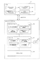
図1は、実施例1のUSBストレージデバイス17(特許請求の範囲に記載のUSBストレージデバイスに相当する)とホスト11(特許請求の範囲に記載の外部装置に相当する)の概略構成を示すブロック図である。
[Example 1]
FIG. 1 is a block diagram illustrating a schematic configuration of a USB storage device 17 (corresponding to a USB storage device described in claims) and a host 11 (corresponding to an external device described in claims) according to the first embodiment. FIG.
(1)ホスト11
ホスト11は、一般に広く知られたパーソナルコンピュータであり、ソフトウェアとして、オペレーションシステム12、ディスクドライブドライバ13及びUSBマスストレージクラスドライバ14を備え、ハードウェアとしてUSBホストコントローラ15を少なくとも備える。
(1)
The
オペレーションシステム12は、ホスト11を統括的に制御するソフトウェアであり、例えばWindows(登録商標)やMac OS X(登録商標)等ある。ディスクドライブドライバ13は、オペレーションシステム12から受け取った記憶装置へのアクセス指令等をSCSIコマンド変換してUSBマスストレージクラスドライバ14に渡すとともに、USBマスストレージクラスドライバ14から指令等を受け取りオペレーションシステム12に渡す。USBマスストレージクラスドライバ14は、USBホストコントローラ15を制御する。USBホストコントローラ15は、図示しないUSBコネクタを備え、他の装置のUSBコネクタとケーブルによって接続されることによって、USB規格に基づいた通信を行うことができるようになっている。なお、ホスト11は、USB規格に基づいた通信を行うことができる機器であれば、パーソナルコンピュータに限らずPDAや携帯電話等であってもよい。
The
(2)USBストレージデバイス17
USBストレージデバイス17は、USBインターフェース19とコントローラ21とLED23とフラッシュメモリ25とを備える。
(2)
The
(2−1)USBインターフェース19
USBインターフェース19は、特許請求の範囲に記載の通信手段に相当し、USBバス16を介してホスト11と通信を行う機能を担う。USBインターフェース19は、パケット送受信部19aとシリアルパラレル変換部19bとパケット生成分解部19cとUSBバスパワー制御部19dとを備える。パケット送受信部19aは、図示しないUSBコネクタと接続され、USB規格に基づいたパケットを送受信する。シリアルパラレル変換部19bは、シリアルデータとパラレルデータとを相互に変換する。パケット生成分解
部19cは、ホスト11と通信を行うためのパケットの生成及びパケットを分解してデータの取り出しを行う。USBバスパワー制御部19dは、ホスト11から供給される電力の管理及びUSBストレージデバイス17の各部位への電力の配分を行う。
(2-1)
The
(2−2)コントローラ21
コントローラ21は、特許請求の範囲に記載の制御手段に相当し、メモリ制御部21aとUSBインターフェース制御部21bとメモリ情報記憶部21cとLED制御部21dとを備える。メモリ制御部21aは、フラッシュメモリ25に対してデータの読み出し、書き込み及び削除を実行する。USBインターフェース制御部21bは、前述したUSBインターフェース19の各部を制御する。メモリ情報記憶部21cは、フラッシュメモリ25の領域に関する情報を記憶する。この情報は、特許請求の範囲に記載の「USBマスストレージクラスドライバのSCSIコマンドセットに定義された論理ユニット番号に対応する領域として前記第1及び第2の領域を前記USBマスストレージクラスドライバに認識させるための情報」に相当する。図2のデータ例を用いてこの情報について説明する。
(2-2)
The
図2に示すように、メモリ情報記憶部21cは、論理ユニット番号31とフォーマット33と書き込み削除可否フラグ35と論理ブロック番号37と物理ブロック番号39とを備える。論理ユニット番号31は論理ユニットを識別するための番号であり、「0」と「1」とが存在する。フォーマット33は、論理ユニット番号31に対応し、その論理ユニットのフォーマットを表す。データ例では、論理ユニット番号「0」は「FAT」フォーマットであり、論理ユニット番号「1」は「ISO9660」フォーマットである。書き込み削除可否フラグ35は、論理ユニット番号31に対応し、その論理ユニットに対して情報の書き込み及び削除の実行可否を表すフラグである。データ例では、論理ユニット番号「0」は「可」であり、論理ユニット番号「1」は「不可」である。論理ブロック番号37は、ホスト11によって指定されるブロック番号であり、論理ユニット毎に定義されている。
As shown in FIG. 2, the memory
このように、フラッシュメモリ25の実ブロック番号である物理ブロック番号39と論理ブロック番号37との対応づけは、メモリ制御部21aによって管理されている。このため、物理ブロック番号39と論理ブロック番号37とは自由に対応付けを行うことができる。また、論理ユニット番号「0」のフォーマットをISO9660にし、論理ユニット番号「1」のフォーマットをFATにしてもよい。また、更に論理ユニットを増やし、ユーザーやアプリケーションによって使い分けられるようになっていてもよい。
As described above, the correspondence between the
(2−3)LED23
図1に戻り、LED23は、フラッシュメモリ25に対して情報の読み出し、書き込み及び削除が実行されている際に点灯する発光体である。フラッシュメモリ25に対して情報の読み出し、書き込み及び削除が実行中であることを利用者に示し、これらの実行中にホスト11からUSBストレージデバイス17が抜かれないようにするためのものである。
(2-3) LED23
Returning to FIG. 1, the
(2−4)フラッシュメモリ25
フラッシュメモリ25は、記憶保持動作が不要な半導体メモリであり、データを記憶することができる。記憶したデータは、メモリ制御部21aによって読み出すことが可能である。また、メモリ制御部21aによって書き込み及び削除をすることもできる。フラッシュメモリ25は、特許請求の範囲に記載の記憶手段に相当する。
(2-4)
The
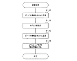
(a)起動処理
USBストレージデバイス17がホスト11に接続された際に、USBストレージデバ
イス17のコントローラ21でプログラムに基づいて実行される起動処理について図3のフローチャートを用いて説明する。この起動処理は、USBストレージデバイス17がホスト11に接続されることにより、USBバスパワー制御部19dに電力が供給され、さらにホスト11側でエニュメレーション処理が実行されると開始される。
(A) Activation Process The activation process executed based on the program by the
起動処理を開始すると、ホスト11からの指令に応じて、ディスクリプタと呼ばれるデバイス情報(デフォルトパイプの最大パケットサイズ等)をホスト11に送信する(S110)。
When the activation process is started, device information called a descriptor (such as the maximum packet size of the default pipe) is transmitted to the
次に、ホスト11から指令に応じて、USBストレージデバイス17のアドレスを設定する(S115)。以降、このアドレス宛のフレームのみを当該USBストレージデバイス17は取得する。
Next, the address of the
次に、より詳細なデバイス情報をホスト11に送信する(S120)。このデバイス情報としては、エンドポイントに関する情報、クラス、サブクラス、プロトコル等である。
その結果、ホスト11ではUSBマスストレージクラスドライバ14が起動され、図示しないアプリケーションソフトウェアからディスクドライブドライバ13とUSBマスストレージクラスドライバ14とを介してUSBホストコントローラ15を制御するアクセスパスができる。なお、このディスクドライブドライバ13は、MS−DOS(登録商標)時代から、受け継がれているドライバであるため永年の技術が積み重ねられており、安定的な動作が得られるドライバである。
Next, more detailed device information is transmitted to the host 11 (S120). The device information includes information regarding end points, classes, subclasses, protocols, and the like.
As a result, the USB mass
続いて、USBマスストレージクラスドライバ14が、Get Max Logical
Unit Numberコマンドによって論理ユニット番号数を要求するため、USBストレージデバイス17は、メモリ情報記憶部21cから論理ユニット番号数が2であるという情報を読み出して、ホスト11に送信する。そしてさらに、ディスクドライブドライバ13がINQUIRYコマンドを発行するため、USBストレージデバイス17は、メモリ情報記憶部21cから論理ユニットのフォーマットに関する情報を読み出して、ホスト11に送信する。これらの結果ホスト11は、USBストレージデバイス17を、FATフォーマットから構成される論理ユニット番号「0」の領域とISO9660フォーマットから構成される論理ユニット番号「1」の領域とを有するデバイスと認識する。
Subsequently, the USB mass
In order to request the number of logical unit numbers by the Unit Number command, the
ホスト11との通信が確立されると、フラッシュメモリ25を動作可能にし(S125)、起動処理を終了する。
なお、Windows(登録商標)には、記憶媒体挿入時や記憶媒体接続時にその記憶媒体のルートディレクトリに記憶されたautorun.infという名称のファイル内で指定されたアプリケーションソフトウェアを実行する機能を有しているため、フラッシュメモリ25の論理ユニット番号「1」の領域にそのファイルを記憶させておけば、本USBストレージデバイス17がホスト11に装着された際に特定のソフトウェアを自動実行させることができる。
When communication with the
In Windows (registered trademark), autorun.com stored in the root directory of a storage medium when the storage medium is inserted or when the storage medium is connected. Since it has a function of executing the application software designated in the file named “inf”, if the file is stored in the area of the logical unit number “1” of the
このようになっていれば、利用者がホスト11の操作に不慣れであっても本USBストレージデバイス17を装着するだけで特定のアプリケーションソフトウェアが自動実行されるため、例えば販促品として広く一般に配布した場合に販促を担うアプリケーションソフトウェアを確実に実行させることができ、販促効果が高まる。
If this is the case, even if the user is unfamiliar with the operation of the
(b)アクセス処理
ホスト11において動作する種々のソフトウェアが、USBストレージデバイス17に対してデータの書き込み、読み出し、削除の実行指令を送ったときに、USBストレージデバイスのコントローラ21でプログラムに基づいて実行されるアクセス処理について図
4のフローチャートを用いて説明する。
(B) Access processing When various software operating in the
まず、S210では、ホスト11から受信した指令の種類によって分岐する。書き込み又は削除の指令であった場合はS215に進み、そうでない場合、すなわち読み出しの指令であった場合はS250に進む。
First, in S210, the process branches depending on the type of command received from the
S215では、書き込み又は削除の指令が論理ユニット番号「1」に対する指令であるか否かによって分岐する。つまり、書き込み及び削除が実行可能な論理ユニットに対するものであるか否かによって分岐する。論理ユニット番号「1」に対するものであればS245に進み、そうでない場合すなわち論理ユニット番号「0」に対する指令であればS220に進む。 In S215, the process branches depending on whether the write or delete command is for the logical unit number “1”. That is, the process branches depending on whether or not the logical unit can be written and deleted. If it is for the logical unit number “1”, the process proceeds to S245; otherwise, that is, if it is a command for the logical unit number “0”, the process proceeds to S220.
S220では、LED23を点灯させる。続くS225では、ホスト11から指定されたフラッシュメモリ25のブロックにデータを書き込む。またはホスト11から指定されたフラッシュメモリ25のブロックのデータを削除する。なお書き込み又は削除を実行する際は、メモリ情報記憶部21cに記憶されているフラッシュメモリ25の領域に関する情報(図2参照)を用い、ホスト11から指定されたブロック番号を論理ブロック番号37としてその論理ブロック番号37に該当する物理ブロック番号39によって特定されたフラッシュメモリ25のブロックに対してデータの書き込み及び削除を実行する。
In S220, the
続くS230では、LED23を消灯させる。そして、S235ではS225の処理が正常に完了したか否かによって分岐する。正常に完了していればアクセス処理を終了し、正常に完了していなかったらS240に進む。
In subsequent S230, the
S240では、S225の処理が正常に完了しなかった旨をホスト11に通知してアクセス処理を終了する。
一方、S215で、書き込み又は削除の指令が論理ユニット番号「1」に対する指令であると判定された際に進むS245では、許可されていない指令としてホスト11にエラー発生の旨を通知する。
In S240, the
On the other hand, in
また、S210で読み込みの指令であったと判定されて進むS250では、LED23を点灯させ、続くS255ではホスト11から指定されたフラッシュメモリ25のブロックのデータを読み込み、読み込んだデータをホスト11に送る。なお、データを読み込む際は、メモリ情報記憶部21cに記憶されているフラッシュメモリ25の領域に関する情報(図2参照)を用い、ホスト11から指定されたブロック番号を論理ブロック番号37としてその論理ブロック番号37に該当する物理ブロック番号39によって特定されたフラッシュメモリ25のブロックからデータを読み込む。
In S250, which is determined to have been a read command in S210, the
続くS260では、LED23を消灯させる。そして、S265ではS255の処理が正常に完了したか否かによって分岐する。正常に完了していればアクセス処理を終了し、正常に完了していなかったらS270に進む。
In subsequent S260, the
S270では、S255の処理が正常に完了しなかった旨をホスト11に通知して通知してアクセス処理を終了する。
このようにアクセス処理が実行されるため、例えば販促品としてUSBストレージデバイス17を利用した場合、誤って消去されると問題のあるソフトウェアを論理ユニット番号「1」の領域に記憶させておけば、そのソフトウェアが消去されることを防止できる。
In S270, the
Since the access process is executed in this way, for example, when the
また、USBストレージデバイス17は、USBマスストレージクラスドライバ14のSCSIコマンドセットに定義された論理ユニット番号に対応する領域として論理ユニッ
ト番号「0」の領域と論理ユニット番号「1」の領域とをUSBマスストレージクラスドライバに認識させるための情報をメモリ情報記憶部21cに保持している。このため、USBマスストレージクラスドライバ14は、USBストレージデバイス17を2つの論理ユニットを有する一つのSCSIデバイスとして認識する。
Further, the
したがって、このような領域の管理を、USB規格におけるエンドポイントの数を増やすことによって実現する場合と比べてコントローラ21を単純化することができる。なぜならエンドポイントの数分だけコントローラ21はFIFOバッファを備えることが必要だからである。また、USBストレージデバイス17に、2種類のUSBストレージデバイスとそれらを接続したハブとを内蔵させて実現させる方法と比べても、USBストレージデバイス17は構成が単純である。また、USBストレージデバイス17であれば、ホスト11が行うUSBマスストレージクラスドライバ14のイニシャライズ処理も1度で済むため、ホスト11がUSBストレージデバイス17を認識するまでの時間も短い。また、ホスト11のオペレーションシステムは、2領域を有する1つのSCSIデバイスとしてUSBストレージデバイス17を管理できるため、複数のデバイスを管理する場合と比べて様々な処理を単純化して実行でき、動作も安定する。
Therefore, the
(c)初期化処理
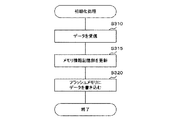
初期化処理は、USBストレージデバイス17の製造者や販売者等(以下「特定ユーザー」と言う)が初期化を行うことを目的として、ホスト11上で初期化ソフトウェアを実行して後述する書き込みボタン66を押下した際に、USBストレージデバイス17のコントローラ21でプログラムに基づいて実行される。
(C) Initialization process The initialization process is performed by the initialization software executed on the
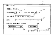
初期化処理を説明する前に、ホスト11で実行される初期化ソフトウェアについて図5の操作画面51を用いて説明する。操作画面51では、特定ユーザーがUSBストレージデバイス17に関する様々なパラメータを設定することができる。
Before describing the initialization process, initialization software executed on the
テキストボックス53は、論理ユニット番号「0」に対応するものであり、情報の読み出し、書き込み及び削除を実行することができる領域(ディスク領域)の容量を入力するためのテキストボックスである。テキストボックス55は、論理ユニット番号「1」に対応するものであり、情報の読み出しのみを実行することができる領域(CD−ROM領域)の容量を入力するためのテキストボックスである。このテキストボックス53とテキストボックス55とに入力した値の合計が全容量である16以下になるよう特定ユーザーは入力しなければならない。
The
テキストボックス57は、USB規格で定義されたシリアル番号を入力するためのテキストボックスである。ホスト11はこのシリアル番号によってデバイスを見分けることができる。
The
テキストボックス59は、固有IDを入力するためのテキストボックスである。固有IDというのは、USB規格で定義されたものではなく、本実施例のUSBストレージデバイス17に独自のものであり、この固有IDをライセンスキーとすることで、不正コピーなどによるコンテンツの不正起動を防止に用いたり、固有IDを認証キーや会員向けサービスに利用したりすることもできる。固有IDは、16バイト以上612バイト以下の16進データである。なお、テキストボックス59の右端の上下ボタンが押下されることにより、表示しきれないデータを順次表示するように操作画面51は構成されている。
The
テキストボックス61は、CD−ROM領域に書き込むファイル名を入力するためのテキストボックスである。複数ファイルのファイル名を入力できるようになっていてもよい。
The
参照ボタン63は、テキストボックス61へのファイル名入力を支援するダイアログボックスを表示させるためのボタンである。表示されたダイアログボックスの中から特定ユーザーがファイル名を選択すると、その選択したファイルがテキストボックス61に表示されるようになっている。
The
フォーマット選択ボタン64は、CDイメージデータのフォーマットを選択するためのダイアログボックスを表示させるためのボタンである。表示されたダイアログボックスの中からISO9660又はHFSの何れかの形式が選択できるようになっている。
The
書き込みボタン66は、特定ユーザーが操作画面51で設定した設定情報をUSBストレージデバイス17に書き込む処理を開始させるためのボタンである。
キャンセルボタン67は、特定ユーザーが操作画面51で設定した設定情報をUSBストレージデバイス17に書き込むことをせずに操作画面51を閉じるためのボタンである。
The
The cancel
次に、USBストレージデバイス17のコントローラ21で実行される初期化処理について図6のフローチャートを用いて説明する。実行が開始されるとまず、ホスト11から送られる設定情報を受信する(S310)。この設定情報は、上述した操作画面51で設定された設定情報である。そして次に、受信した設定情報に基づいてメモリ情報記憶部21cのデータを更新する(S315)。
Next, initialization processing executed by the
続いて、受信した設定情報に基づいてフラッシュメモリ25の論理ユニット番号「1」の領域にデータを書き込み(S320)、初期化処理は終了する。本来は、論理ユニット番号「1」の領域にはデータを書き込むことはできないが、初期化処理の際のみ、書き込むことができるように構成されている。なお、書き込むデータは、上述したテキストボックス61で設定したファイルである(図5参照)。
Subsequently, based on the received setting information, data is written in the area of the logical unit number “1” of the flash memory 25 (S320), and the initialization process ends. Originally, data cannot be written in the area of the logical unit number “1”, but it can be written only in the initialization process. The data to be written is a file set in the
このような初期化処理によって特定ユーザーの事情に合わせて、領域の容量の変更や、シリアル番号の設定や、固有IDの設定や、CD−ROM領域に予めファイルを記憶させておくことが実行できる。 By such initialization processing, it is possible to change the capacity of the area, set the serial number, set the unique ID, or store the file in the CD-ROM area in advance according to the circumstances of the specific user. .
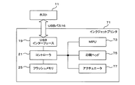
[実施例2]
図7は、実施例2のインクジェットプリンタ71(特許請求の範囲に記載のUSBストレージデバイスに相当する)とホスト11(特許請求の範囲に記載の外部装置に相当する)との概略構成を示すブロック図である。なお、実施例1と同様の部分は、実施例1を説明する際に使用した符号と同一の符号を付すことにより説明を省略する。
[Example 2]
FIG. 7 is a block diagram illustrating a schematic configuration of the inkjet printer 71 (corresponding to the USB storage device described in claims) and the host 11 (corresponding to the external device described in claims) according to the second embodiment. FIG. The same parts as those in the first embodiment are denoted by the same reference numerals as those used in the description of the first embodiment, and the description thereof is omitted.
インクジェットプリンタ71は、USBインターフェース19とコントローラ21とフラッシュメモリ25とMPU73と印字ヘッド75とアクチュエータ77とを備える。このうちUSBインターフェース19が特許請求の範囲に記載の通信手段に相当し、コントローラ21が制御手段に相当し、フラッシュメモリ25が記憶手段に相当する。また、MPU73と印字ヘッド75とアクチュエータ77とが特許請求の範囲に記載の印刷手段に相当する。
The
MPU73は、USBインターフェース19及びコントローラ21を介してホスト11と通信を行うと共に、図示しない各種センサからの情報に基づいて印字ヘッド75及びアクチュエータ77の動作を制御する。なお、実施例2では、コントローラ21とMPU73とは別構成としているが、それらの機能の一部及び全部をMPU73に移行させてもよい。
The
印字ヘッド75は、インクノズルを有し、インクノズルから所定の色のインクを吐出させ、印刷用紙にインクを定着させることができる。
アクチュエータ77は、図示しないフィードローラモータ、紙送りローラモータ、印字ヘッド駆動モータ等から構成され、これらを適切に動作させることにより、印刷用紙の位置及び印字ヘッド75の位置関係を調整して所望の印刷結果が得られるようにする。
The
The
フラッシュメモリ25の論理ユニット番号「1」の領域(CD−ROM領域)には、印刷するデータをホスト11で扱うためのアプリケーションソフトウェアが予め格納されており、ホスト11はそのようなアプリケーションソフトウェアを有していなくても、フラッシュメモリ25のCD−ROM領域から読み込むことにより使用することができる。
Application software for handling data to be printed by the
これに対して、従来は、印刷機能を提供するドライバプログラム、印刷管理ソフトウェアなどをホスト11が有していない場合には、別途CD−ROMやフレキシブルディスクなどの媒体から取り込むか、インターネット等からダウンロードしてインストールする必要があった。そのため、CD−ROMやフレキシブルディスクのドライブを通常有していないPDAなどは、それらの媒体から取り込むことは困難であった。このような点で、実施例2のインクジェットプリンタ71は、従来と比べて優位な効果を有する。
On the other hand, conventionally, when the
また、アプリケーションソフトウェアはフラッシュメモリ25のCD−ROM領域に格納されるため、エンドユーザーによって誤って消去されてしまうおそれがない。また、ディスク領域(論理ユニット番号「0」の領域)には、印刷するための印刷データを格納することにより、ディスク領域を介して複数のホスト11で印刷データを共有することも可能になる。このような点でも、実施例2のインクジェットプリンタ71は、従来と比べて優位な効果を有する。
In addition, since the application software is stored in the CD-ROM area of the
また、実施例1で述べたような固有IDを実装してその固有IDを認証キーとして用いるようにすれば、特定のユーザーのみがインクジェットプリンタ71を使用できるようにしたり、特定のユーザーのみがCD−ROM領域に格納されたアプリケーションソフトウェア利用できるようにしたりすることができる。
Further, if the unique ID as described in the first embodiment is implemented and the unique ID is used as an authentication key, only a specific user can use the
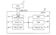
[実施例3]
図8は、実施例3のスキャナ81(特許請求の範囲に記載のUSBストレージデバイスに相当する)とホスト11(特許請求の範囲に記載の外部装置に相当する)との概略構成を示すブロック図である。なお、実施例1と同様の部分は、実施例1を説明する際に使用した符号と同一の符号を付すことにより説明を省略する。
[Example 3]
FIG. 8 is a block diagram showing a schematic configuration of the scanner 81 (corresponding to the USB storage device described in the claims) and the host 11 (corresponding to the external device described in the claims) of the third embodiment. It is. The same parts as those in the first embodiment are denoted by the same reference numerals as those used in the description of the first embodiment, and the description thereof is omitted.
スキャナ81は、USBインターフェース19とコントローラ21とフラッシュメモリ25とMPU83とCCD85とアクチュエータ97とを備える。このうちUSBインターフェース19が特許請求の範囲に記載の通信手段に相当し、コントローラ21が制御手段に相当し、フラッシュメモリ25が記憶手段に相当する。また、MPU73とCCD85とアクチュエータ87とが特許請求の範囲に記載のスキャナ手段に相当する。
The
MPU83は、USBインターフェース19及びコントローラ21を介してホスト11と通信を行うと共に、CCD85及びアクチュエータ87の動作を制御する。なお、実施例3では、コントローラ21とMPU83とは別構成としているが、それらの機能の一部及び全部をMPU83に分担させてもよい。
The
CCD85は、光情報を電気信号に変換する半導体素子であり、任意の対象物を画像データとして読み取って出力することができる。
アクチュエータ87は、図示しない光源駆動モータやCCD駆動モータ等から構成され、これらが適切に動作することにより、任意の対象物の所望の範囲の画像データを得ることができる。
The
The
フラッシュメモリ25の論理ユニット番号「1」の領域(CD−ROM領域)には、するデータをホスト11で扱うためのアプリケーションソフトウェアが予め格納されており、ホスト11はそのようなアプリケーションソフトウェアを有していなくても、フラッシュメモリ25のCD−ROM領域から読み込むことにより使用することができる。
In the area (CD-ROM area) of the logical unit number “1” of the
これに対して、従来は、スキャナ81の制御機能を提供するドライバプログラム、画像データの加工ソフトウェアなどをホスト11が有していない場合には、別途CD−ROMやフレキシブルディスクなどの媒体から取り込むか、インターネット等からダウンロードしてインストールする必要があった。そのため、CD−ROMやフレキシブルディスクのドライブを通常有していないPDAなどにおいては、それらの媒体から取り込むのは困難であった。このような点で、実施例3のスキャナ81は、従来と比べて優位な効果を有す
る。
On the other hand, conventionally, if the
また、アプリケーションソフトウェアはフラッシュメモリ25のCD−ROM領域に格納されるため、エンドユーザーによって誤って消去されてしまうおそれがないとともに、ディスク領域(論理ユニット番号「0」の領域)には、画像データを格納することにより、ディスク領域を介して複数のホスト11で画像データを共有することも可能になる。このような点でも、実施例3のスキャナ81は、従来と比べて優位な効果を有する。
In addition, since the application software is stored in the CD-ROM area of the
以上、実施例を3つ説明したが、他の実施例について説明する。
実施例2のインクジェットプリンタ71や実施例3のスキャナ81の技術思想をUSBインターフェースを有する他の装置に適用してもよい。具体的には、デジタルカメラ、携帯端末、スピーカー、キーボード、マウス、モデム装置、ハンドセット、カードアダプタ等に適用してもよい。これらに適用しても上記実施例と同様の効果が得られる。
Although three embodiments have been described above, other embodiments will be described.
The technical ideas of the
また、実施例1の操作画面51(図5参照)は、CDイメージデータのフォーマットとしてISO9660又はHFSの何れかの形式が選択できるようになっていたが、さらに、Audio CD、CD TEXT、Mixed CD、Enhanced CD、ビデオCD、ブータブルCD等フォーマットが選択できるようになっていてもよい。また、記録方式も、ディスクアットワンス、トラックアットワンス、セッションアットワンス、パケットライトなどの方式が指定できるようになっていてもよい。 In addition, the operation screen 51 (see FIG. 5) of the first embodiment can select either ISO9660 or HFS as the format of the CD image data, but further, Audio CD, CD TEXT, Mixed CD. , Enhanced CD, video CD, bootable CD, and other formats can be selected. As the recording method, a method such as disk-at-once, track-at-once, session-at-once, or packet write may be designated.
11…ホスト、12…オペレーションシステム、13…ディスクドライブドライバ、14…USBマスストレージクラスドライバ、15…USBホストコントローラ、16…USBバス、17…USBストレージデバイス、19a…USBインターフェース、19b
…シリアルパラレル変換部、19c…パケット生成分解部、19d…USBバスパワー制御部、21…コントローラ、21a…メモリ制御部、21b…USBインターフェース制御部、21c…メモリ情報記憶部、21d…LED制御部、23…LED、25…フラッシュメモリ、71…インクジェットプリンタ、73…MPU、75…印字ヘッド、77…アクチュエータ、81…スキャナ、83…MPU、85…CCD、87…アクチュエータ
DESCRIPTION OF
... Serial / parallel converter, 19c ... Packet generation / disassembly part, 19d ... USB bus power control part, 21 ... Controller, 21a ... Memory control part, 21b ... USB interface control part, 21c ... Memory information storage part, 21d ... LED control part , 23 ... LED, 25 ... flash memory, 71 ... inkjet printer, 73 ... MPU, 75 ... print head, 77 ... actuator, 81 ... scanner, 83 ... MPU, 85 ... CCD, 87 ... actuator
Claims (6)
半導体メモリを用いて情報を記憶する記憶手段と、
前記外部装置とUSBプロトコルに基づいた通信を行う通信手段と、
前記通信手段を介して前記外部装置から受け取った指令に基づいて、前記記憶手段に対して情報の読み出し、書き込み及び削除を実行する制御手段と、
を備え、
前記制御手段は、前記記憶手段を第1の領域と第2の領域とに分け、前記第1の領域に対しては前記指令に基づいて情報の読み出し、書き込み及び削除を実行し、前記第2の領域に対しては前記指令に基づいて情報の読み出しのみを実行し、更に、前記外部装置が有するUSBマスストレージクラスドライバのSCSIコマンドセットに定義された論理ユニット番号に対応する領域として前記第1及び第2の領域を前記USBマスストレージクラスドライバに認識させるための情報を保持し、前記USBマスストレージクラスドライバに本USBストレージデバイスを2つの論理ユニットを有する一つのSCSIデバイスとして認識させることを特徴とするUSBストレージデバイス。 A USB storage device that can be attached to and detached from an external device,
Storage means for storing information using a semiconductor memory;
A communication means for performing communication based on the USB protocol with the external device;
Control means for executing reading, writing and deletion of information with respect to the storage means based on a command received from the external device via the communication means;
With
The control unit divides the storage unit into a first region and a second region, and reads, writes, and deletes information on the first region based on the command. Only the reading of information is executed based on the command, and the first area is the area corresponding to the logical unit number defined in the SCSI command set of the USB mass storage class driver of the external device. And holding information for causing the USB mass storage class driver to recognize the second area, and causing the USB mass storage class driver to recognize the USB storage device as one SCSI device having two logical units. USB storage device.
更に、前記通信手段を介して前記外部装置から送られる指令に基づいて印刷を行う印刷手段を備えることを特徴とするUSBストレージデバイス。 The USB storage device of claim 1,
The USB storage device further comprises printing means for performing printing based on a command sent from the external device via the communication means.
更に、前記通信手段を介して前記外部装置から送られる指令に基づいて任意の対象物を画像データとして読み取るスキャナ手段を備えることを特徴とするUSBストレージデバイス。 The USB storage device according to claim 1 or 2,
The USB storage device further comprises scanner means for reading an arbitrary object as image data based on a command sent from the external device via the communication means.
前記印刷手段又は前記スキャナ手段は、前記記憶手段に対する情報の読み出し、書き込み及び削除の少なくとも何れか1つを前記制御手段に指令することを特徴とするUSBストレージデバイス。 The USB storage device according to claim 2 or claim 3,
The USB storage device, wherein the printing unit or the scanner unit instructs the control unit to read, write, and delete information from the storage unit.
前記記憶手段は、前記第2の領域に、前記外部装置が当該USBストレージデバイスの前記印刷手段又は前記スキャナ手段の少なくとも一方を制御するためのアプリケーションソフトウェアを記憶していることを特徴とするUSBストレージデバイス。 The USB storage device according to any one of claims 2 to 4,
The storage means stores, in the second area, application software for the external device to control at least one of the printing means or the scanner means of the USB storage device. device.
Priority Applications (1)
| Application Number | Priority Date | Filing Date | Title |
|---|---|---|---|
| JP2005092148A JP2005243046A (en) | 2002-05-29 | 2005-03-28 | Usb storage device and program |
Applications Claiming Priority (2)
| Application Number | Priority Date | Filing Date | Title |
|---|---|---|---|
| JP2002155684 | 2002-05-29 | ||
| JP2005092148A JP2005243046A (en) | 2002-05-29 | 2005-03-28 | Usb storage device and program |
Related Parent Applications (1)
| Application Number | Title | Priority Date | Filing Date |
|---|---|---|---|
| JP2003365044A Division JP3699717B2 (en) | 2002-05-29 | 2003-10-24 | USB storage device and control device thereof |
Related Child Applications (1)
| Application Number | Title | Priority Date | Filing Date |
|---|---|---|---|
| JP2005285284A Division JP3914949B2 (en) | 2002-05-29 | 2005-09-29 | USB storage device, control device thereof, and program for causing control device to execute |
Publications (2)
| Publication Number | Publication Date |
|---|---|
| JP2005243046A true JP2005243046A (en) | 2005-09-08 |
| JP2005243046A5 JP2005243046A5 (en) | 2005-11-17 |
Family
ID=35024645
Family Applications (1)
| Application Number | Title | Priority Date | Filing Date |
|---|---|---|---|
| JP2005092148A Withdrawn JP2005243046A (en) | 2002-05-29 | 2005-03-28 | Usb storage device and program |
Country Status (1)
| Country | Link |
|---|---|
| JP (1) | JP2005243046A (en) |
-
2005
- 2005-03-28 JP JP2005092148A patent/JP2005243046A/en not_active Withdrawn
Similar Documents
| Publication | Publication Date | Title |
|---|---|---|
| KR100954933B1 (en) | Usb storage device and control device | |
| JP3513147B2 (en) | USB storage device and its control device | |
| US7068386B2 (en) | Image processing system, image data processing method, and storage medium | |
| JP3914949B2 (en) | USB storage device, control device thereof, and program for causing control device to execute | |
| WO2005086002A1 (en) | Method for data processing device exchanging data with computer | |
| JP2010044579A (en) | Peripheral device, program, and driver installation system | |
| JP2006079634A5 (en) | ||
| US20050102441A1 (en) | System with application program and method for automatically installing the application program | |
| JP2008139916A (en) | Information processing apparatus, control method for information processing apparatus, and control program for information processing apparatus | |
| JP3699717B2 (en) | USB storage device and control device thereof | |
| JP2004171536A5 (en) | ||
| JP4551643B2 (en) | USB printer and USB scanner | |
| JP4242798B2 (en) | USB storage device and control device thereof | |
| JP2001326766A (en) | Image processing system, image data processing method and storage medium | |
| JP4087788B2 (en) | Information processing apparatus, control method therefor, and program | |
| JP2006293638A (en) | Information processor and peripheral equipment | |
| JP2005243046A (en) | Usb storage device and program | |
| JP2005243046A5 (en) | ||
| JP4276219B2 (en) | USB storage device internal state setting method | |
| JP3814461B2 (en) | Printer, printer control method, and storage medium | |
| US8675223B2 (en) | Image forming device, image forming system and computer readable medium for installing related software to another device | |
| JP2006181735A (en) | Data outputting apparatus and information processing apparatus | |
| JP2005038297A (en) | Installation method of device driver, and system used for it | |
| Meyers et al. | Printing, Peripherals, and Bluetooth in Snow Leopard | |
| JP2001322335A (en) | Image processing system, image data processing method and storage medium |
Legal Events
| Date | Code | Title | Description |
|---|---|---|---|
| A521 | Written amendment |
Effective date: 20050929 Free format text: JAPANESE INTERMEDIATE CODE: A523 |
|
| A621 | Written request for application examination |
Effective date: 20050929 Free format text: JAPANESE INTERMEDIATE CODE: A621 |
|
| A871 | Explanation of circumstances concerning accelerated examination |
Free format text: JAPANESE INTERMEDIATE CODE: A871 Effective date: 20050929 |
|
| A975 | Report on accelerated examination |
Free format text: JAPANESE INTERMEDIATE CODE: A971005 Effective date: 20051024 |
|
| A131 | Notification of reasons for refusal |
Free format text: JAPANESE INTERMEDIATE CODE: A131 Effective date: 20051108 |
|
| A521 | Written amendment |
Free format text: JAPANESE INTERMEDIATE CODE: A523 Effective date: 20051221 |
|
| A02 | Decision of refusal |
Free format text: JAPANESE INTERMEDIATE CODE: A02 Effective date: 20060117 |
|
| A521 | Written amendment |
Effective date: 20060320 Free format text: JAPANESE INTERMEDIATE CODE: A523 |
|
| A911 | Transfer of reconsideration by examiner before appeal (zenchi) |
Effective date: 20060501 Free format text: JAPANESE INTERMEDIATE CODE: A911 |
|
| A912 | Removal of reconsideration by examiner before appeal (zenchi) |
Effective date: 20060519 Free format text: JAPANESE INTERMEDIATE CODE: A912 |
|
| A761 | Written withdrawal of application |
Free format text: JAPANESE INTERMEDIATE CODE: A761 Effective date: 20090407 |