JP2008139916A - Information processing apparatus, control method for information processing apparatus, and control program for information processing apparatus - Google Patents
Information processing apparatus, control method for information processing apparatus, and control program for information processing apparatus Download PDFInfo
- Publication number
- JP2008139916A JP2008139916A JP2006322720A JP2006322720A JP2008139916A JP 2008139916 A JP2008139916 A JP 2008139916A JP 2006322720 A JP2006322720 A JP 2006322720A JP 2006322720 A JP2006322720 A JP 2006322720A JP 2008139916 A JP2008139916 A JP 2008139916A
- Authority
- JP
- Japan
- Prior art keywords
- information processing
- processing apparatus
- unit
- usb
- installation
- Prior art date
- Legal status (The legal status is an assumption and is not a legal conclusion. Google has not performed a legal analysis and makes no representation as to the accuracy of the status listed.)
- Pending
Links
Images


Classifications
-
- G—PHYSICS
- G06—COMPUTING; CALCULATING OR COUNTING
- G06F—ELECTRIC DIGITAL DATA PROCESSING
- G06F9/00—Arrangements for program control, e.g. control units
- G06F9/06—Arrangements for program control, e.g. control units using stored programs, i.e. using an internal store of processing equipment to receive or retain programs
- G06F9/44—Arrangements for executing specific programs
- G06F9/4401—Bootstrapping
- G06F9/4411—Configuring for operating with peripheral devices; Loading of device drivers
Landscapes
- Engineering & Computer Science (AREA)
- Software Systems (AREA)
- Theoretical Computer Science (AREA)
- Computer Security & Cryptography (AREA)
- Physics & Mathematics (AREA)
- General Engineering & Computer Science (AREA)
- General Physics & Mathematics (AREA)
- Stored Programmes (AREA)
- Accessory Devices And Overall Control Thereof (AREA)
- Information Transfer Systems (AREA)
Abstract
Description
本発明は、ホスト装置に接続され周辺機器として所定の情報処理を行なう情報処理手段を有する情報処理装置、情報処理装置の制御方法、および情報処理装置の制御プログラムに関するものである。 The present invention relates to an information processing apparatus having information processing means connected to a host apparatus and performing predetermined information processing as a peripheral device, a method for controlling the information processing apparatus, and a control program for the information processing apparatus.
近年、パーソナルコンピュータ(以下PC)のようなホスト装置に接続して用いられる周辺機器として複合機化された装置が現われている。たとえば、プリンタでは、印刷出力機器としてPCに接続するために、USB(ユニバーサル・シリアル・バス)などのインターフェースが設けられている。さらに、このようなプリンタでは、メモリカードリーダを有し、デジタルカメラなどで撮影されたメモリカード内の画像をPCレスでプリンタへ直接印刷できるようになっているものがある。 2. Description of the Related Art In recent years, a multi-function device has appeared as a peripheral device used by connecting to a host device such as a personal computer (hereinafter referred to as a PC). For example, in a printer, an interface such as a USB (Universal Serial Bus) is provided to connect to a PC as a print output device. Further, some of such printers have a memory card reader so that images in a memory card taken by a digital camera or the like can be directly printed on the printer without a PC.
上記のようにメモリカードリーダを設けたプリンタでは、USBのようなインターフェースを介して、メモリカードもPCから認識させることにより、PCカードリーダとしての機能も持たせる構成が知られている(たとえば下記の特許文献1参照)。 A printer having a memory card reader as described above is known to have a function as a PC card reader by recognizing a memory card from a PC via an interface such as a USB (for example, the following). Patent Document 1).
このように、複数の機能を持つPC周辺機器は、その複数の機能をPCに認識させることにより、PC側から見るとあたかも複数の機器が繋がっているように動作させることができる。 Thus, a PC peripheral device having a plurality of functions can be operated as if a plurality of devices are connected when viewed from the PC side by causing the PC to recognize the plurality of functions.
これらの複数の機能を別々の機器としてPCに認識させるためには周辺機器側のインターフェース制御だけでなく、PC側のOSにドライバをインストールする必要がある。最新のOSではキーボード、マウスなどの一般的な機器のドライバは既にOSに持っている。先に例を挙げたメモリカードリーダやハードディスクなど、USB規格ではストレージクラスと呼ばれるクラスの機器も同様である。したがって、キーボード、マウス、ストレージクラスのメモリカードリーダやハードディスクなどのデバイスは、USBを介して接続するだけで、自動でドライバがロードされ、直ちにメモリカードやハードディスクの内容にアクセスできるようになる。
一方、プリンタやイメージスキャナなど、制御が機種毎に大きく違う周辺機器のドライバを共通化することは非常に難しい。そこで、プリンタやイメージスキャナなどの周辺機器については、各メーカがそれぞれの専用ドライバを記録したCDなどのメディアを周辺機器の製品パッケージに同梱することが必要であった。 On the other hand, it is very difficult to share drivers for peripheral devices such as printers and image scanners whose control differs greatly depending on the model. Therefore, for peripheral devices such as printers and image scanners, it has been necessary for each manufacturer to bundle media such as a CD on which the dedicated driver is recorded in the product package of the peripheral device.
通常、ドライバをインストールした後に周辺機器をUSBで接続すれば、その周辺機器がOSに認識され、使用できるようになる。しかし、もしユーザがその手順を知らずにドライバをインストールしないで、周辺機器を先に接続するとOSでダミーのドライバを割り当ててしまうことがあり、この場合は後からドライバをインストールしても機器を正常に動作させることができない、という問題があった。また、OSによってはこの状態から復帰するには、インストールされたダミードライバを特別な手順により削除する必要があった。 Normally, if a peripheral device is connected by USB after installing the driver, the peripheral device is recognized by the OS and can be used. However, if the user does not install the driver without knowing the procedure and the peripheral device is connected first, a dummy driver may be assigned by the OS. In this case, even if the driver is installed later, the device is operating normally. There was a problem that it could not be operated. Further, in order to recover from this state depending on the OS, it is necessary to delete the installed dummy driver by a special procedure.
専用ドライバを記録したCDなどのメディアを同梱しなくても良いような構成として、周辺機器を複合機能化し、周辺機器にストレージクラスを搭載し、このストレージ内にドライバを格納しておく構成が知られている(たとえば上記の特許文献2)。 As a configuration that does not require the inclusion of a CD or other media that records the dedicated driver, the peripheral device has a multi-function, a storage class is installed in the peripheral device, and the driver is stored in this storage. Known (for example, Patent Document 2 above).
このような構成によれば、ドライバCDを同梱する必要はなくなるが、ダミードライバによって動作しなくなる問題と、ダミードライバの削除の必要がある問題は解決できない。 According to such a configuration, it is not necessary to bundle the driver CD, but the problem that the dummy driver does not operate and the problem that the dummy driver needs to be deleted cannot be solved.
また、ドライバをインストールする前にユーザが誤って機器をPCに接続してしまわないように、周辺機器によってはUSBポートに手順を記した保護シールを貼っている例もあるが、これはユーザの注意を促して問題を回避しようするだけのものであり、根本解決ではない。また、このような配慮のために、シールの印刷費や、シール貼付工数の負担増となる問題があった。 In addition, some peripheral devices have a protective seal with instructions on the USB port to prevent the user from accidentally connecting the device to the PC before installing the driver. It's just a way to call attention and avoid problems, not a fundamental solution. In addition, due to such considerations, there has been a problem that the printing cost of the seal and the burden of sticker man-hours increase.
本発明の課題は、上述の問題を解決し、初めて周辺機器をホスト装置に接続する時に、容易かつ確実に周辺機器のドライバソフトウェアをホスト装置にインストールでき、周辺機器を正常に動作させることができるようにすることにある。 An object of the present invention is to solve the above-mentioned problems, and when connecting a peripheral device to a host device for the first time, driver software for the peripheral device can be easily and reliably installed in the host device, and the peripheral device can be operated normally. There is in doing so.
本発明は、ホスト装置に接続され周辺機器として所定の情報処理を行なう情報処理手段と、前記ホスト装置が前記情報処理手段を用いるためにホスト装置上で動作するドライバソフトウェアおよび該ドライバソフトウェアのインストーラを格納したストレージ手段と、前記情報処理手段、および前記ストレージ手段を前記ホスト装置と接続可能なインターフェース手段とを有する情報処理装置、その制御方法、およびその制御プログラムにおいて、前記ドライバソフトウェアが前記ホスト装置に対して未インストールであるか、またはインストール済みであるかのいずれかの値を記録するインストールフラグを用い、前記インターフェース手段にホスト装置が接続された時、前記インストールフラグが前記未インストールを示す値となっていれば前記インストーラを読み出して実行すべく前記ホスト装置が前記ストレージ手段のみにアクセスできるよう前記インターフェース手段を制御し、一方、前記インストールフラグが前記インストール済みを示す値となっていれば前記ホスト装置が前記ストレージ手段および前記情報処理手段にアクセスできるよう前記インターフェース手段を制御する構成を採用した。 The present invention includes an information processing unit that is connected to a host device and performs predetermined information processing as a peripheral device, driver software that operates on the host device so that the host device uses the information processing unit, and an installer of the driver software In an information processing apparatus having a stored storage means, the information processing means, and an interface means capable of connecting the storage means to the host device, a control method thereof, and a control program thereof, the driver software is stored in the host device. When the host device is connected to the interface means using an install flag that records either a value that is not installed or has been installed, the install flag is a value indicating the non-installed state. Has become For example, the host device controls the interface unit so that the host device can access only the storage unit to read and execute the installer. On the other hand, if the installation flag is a value indicating the installed, the host device A configuration is adopted in which the interface means is controlled so that the storage means and the information processing means can be accessed.
上記構成によれば、ホスト装置に情報処理手段のドライバソフトウェアが未インストールである状態では、ホスト装置がストレージ手段のみにアクセスできるようインターフェース手段が制御される。このため、従来のように誤まったドライバやダミードライバがインストールされてしまうことにより発生する問題を回避することができる。情報処理手段のドライバソフトウェアは、ユーザ操作や、デバイス接続時の自動処理によりストレージ手段に用意されているインストーラを実行することにより、容易かつ確実にインストールすることができる。このように、本発明によれば、初めて周辺機器をホスト装置に接続する時に、容易かつ確実に周辺機器のドライバソフトウェアをホスト装置にインストールでき、周辺機器を正常に動作させることができる。 According to the above configuration, when the driver software of the information processing means is not installed in the host device, the interface means is controlled so that the host device can access only the storage means. For this reason, it is possible to avoid a problem that occurs when an erroneous driver or dummy driver is installed as in the prior art. The driver software of the information processing means can be easily and reliably installed by executing an installer prepared in the storage means by user operation or automatic processing at the time of device connection. As described above, according to the present invention, when the peripheral device is connected to the host device for the first time, the driver software of the peripheral device can be easily and surely installed in the host device, and the peripheral device can be operated normally.
以下、図面を参照して、発明を実施するための最良の形態の例として2つの実施例を示す。以下の各実施例では、周辺機器としてプリンタを例示し、そのドライバソフトウェアをホスト装置であるPCに確実にインストールさせるための構成を例示する。なお、以下の周辺機器としてのプリンタはあくまでも一例であり、本発明はイメージスキャナにストレージという構成、その両方、プリンタとイメージスキャナの複合機にストレージを搭載した構成などとして実施でき、本発明における周辺機器の主機能はプリンタである必要はない。 Hereinafter, with reference to the drawings, two examples will be shown as examples of the best mode for carrying out the invention. In each of the following embodiments, a printer is exemplified as a peripheral device, and a configuration for reliably installing the driver software on a PC that is a host device is illustrated. Note that the following printer as a peripheral device is merely an example, and the present invention can be implemented as a configuration in which an image scanner has storage, a configuration in which both a printer and an image scanner are equipped with storage, and the like in the present invention. The main function of the device need not be a printer.
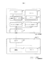
図1と図3は本発明で周辺機器をコンパウンドデバイスとした構成を示している。一般にUSB機器において、コンパウンド構成とは複数の機能部と、USBハブを内蔵した構成をいう。 1 and 3 show a configuration in which the peripheral device is a compound device according to the present invention. In general, in a USB device, a compound configuration refers to a configuration in which a plurality of functional units and a USB hub are incorporated.
図において、周辺機器100は、制御部(制御手段)101、本周辺機器の主な情報処理を行なう情報処理手段としてのプリンタ(画像記録手段)102、およびストレージ(ストレージ手段)103を含む。ストレージ103には、ホスト装置としてのPC200のOS上でプリンタ102を動作させるためのドライバ104が格納されている。
In the figure, a peripheral device 100 includes a control unit (control means) 101, a printer (image recording means) 102 as information processing means for performing main information processing of the peripheral device, and a storage (storage means) 103. The
周辺機器100は、PC200と接続するインターフェース手段としてUSBハブ110を有する。USBハブ110には、プリンタ102をUSBプリンタとして動作させるプリンタクラスのUSBデバイス111、およびストレージ103をUSBストレージとして動作させるストレージクラスのUSBデバイス112が接続されている。
The peripheral device 100 includes a
制御部101は、CPUおよびRAM、後述のプログラムを記録したROM、あるいはさらに不揮発ROMなどのメモリデバイスから構成される。後述する制御プログラムは、たとえばこのROM部に記録しておくことができる。周辺機器100の各ブロックは、制御部101に対してバス、制御線などで接続され、制御部101の制御を受ける。
The
制御部101のメモリ部の適当なアドレスにはインストールフラグ105が割り付けられている。インストールフラグ105は、後述のようにそのフラグの状態によって、USBハブ110とプリンタクラスUSBデバイス111との接続状態を変化させるために用いられる。
An installation flag 105 is assigned to an appropriate address in the memory unit of the
インストールフラグ105は、好ましくは不揮発性のROMやバッテリーバックアップメモリ、あるいは場合によってはハードディスクなど、AC電源オフ/オンによってメモリ内容が消えないメモリデバイス上に配置する。 The installation flag 105 is preferably arranged on a memory device such as a nonvolatile ROM, a battery backup memory, or a hard disk in some cases where the memory contents are not erased by AC power off / on.
インストールフラグ105は、”未インストール”と”インストール済み”の2つの状態を記憶でき、工場出荷時は”未インストール”となっている。もちろん、ストレージ103にインストールフラグの状態を記録しておいてもよい。
The installation flag 105 can store two states of “not installed” and “installed”, and is “not installed” at the time of shipment from the factory. Of course, the status of the installation flag may be recorded in the
インストールフラグ105は、制御部101により”未インストール”と”インストール済み”の2つの状態に切り替えられる。この状態に応じて後述のように周辺機器100内部のUSB接続を変化させる制御が行なわれる。なお、図1、図3ではインストールフラグ105は制御部101に内蔵されているが、ストレージ103は制御部の他の記憶装置と兼用してもかまわないので、たとえばストレージ103に記録されていてもよい。
The installation flag 105 is switched between two states of “not installed” and “installed” by the
プリンタ102は、インクジェット方式など適当な記録方式で記録媒体に印刷する能力を有するとともに、その他給紙、排紙等の機能を有するプリンタエンジンから構成され、制御部101によって制御される。
The
ストレージ103は、ROM、RAM、HDDなどから構成された記憶装置で、PC200のOS上でプリンタ102を動作させるためのドライバ104を記録している。これは読み書き可能であっても読み込み専用であってもかまわないし、先述の制御部101のROM、RAMなどと共用してもかまわない。
The
ドライバ104は、PC200のOSで動作するデバイスドライバである。ドライバ104は、PC200にプリンタクラスUSBデバイス111を制御する機能と、後述するがPC200から周辺機器100に対してドライバのインストールが完了したことを伝える機能を提供する。また、ドライバ104には、ドライバ104自身をインストールするインストーラ、インストーラをPC200で自動実行する設定ファイルが含まれている。
The
USBハブ110とプリンタクラスUSBデバイス111とストレージクラスUSBデバイス112は全てUSBの規格を満たす。これらとPC200はそれぞれ図のようにUSBで接続されている。図中[H]をホスト側、[D]がデバイス側の接続を表す。本実施例ではホスト/デバイスの区別は図示の通りとするが、USBOnTheGoなど別の規格を用いる場合、ホスト/デバイスの組合せはこの通りでなくてもよい。
The
USBハブ110は図示の通りに接続され、インストールフラグの状態により制御部101の制御によってストレージクラスUSBデバイス112との接続をオン/オフできるものとする。
The
プリンタクラスUSBデバイス111はUSBデバイス機能を持ち、ディスクリプタ、エンドポイントの構成は図8に示すようになっている。図8に示すように、プリンタクラスUSBデバイス111はディスクリプタをホストに返したりデータ送受信できる。また、本実施例の周辺機器100はプリンタ102を有しているため、プリンタクラスを実装するものとする。もし、周辺機器100が情報処理手段としてイメージスキャナなどを持つ場合は、さらに別にスチルイメージクラスをコンポジット/コンパウンド構成で持つ必要がある。
The printer
また、ストレージクラスUSBデバイス112はUSBデバイス機能を持ち、ディスクリプタ、エンドポイントの構成は図7に示すようになっている。USBデバイス112は図7のように、該当クラスのディスクリプタをホストに返したりデータ送受信でき、ストレージ103をホストからアクセスできるものとする。
The storage
PC200は制御部201、ストレージ202、USBホスト203などから構成される。PC200は一般的なPCでもいいし、PDAやシンクライアントであってもかまわない。特に、本発明ではメモリ・ハードディスク容量が小さくOS付属ドライバを持たないPDAやシンクライアントにおいて効果を発揮するものである。
The
制御部201はCPU、ストレージ202と、それ以外のROM、RAM等のストレージ、USBホスト203とそれ以外のインターフェースなど、PCを構成するのに必要な全てを含み、それぞれバスおよび制御線で接続されている。本実施例と直接関係のないストレージ202とUSBホスト203以外の構成については図示を省略してある。
The
PC200のストレージ202は、一般的なPCではHDDやメモリ、PDAやシンクライアントではROM、RAMなどのメモリから構成され、上述のドライバ104はこのストレージ202上にインストールされる。
The
また、PC200のUSBホスト203はUSB規格のホスト機能を有し、USBデバイス機器を接続、制御でき、USBプロトコルに沿ってデータの送受信を行なうことができる。
The
次に上記構成における動作につき説明する。ここでは、まず周辺機器100をPC200に接続して動作可能になるまでの流れを説明する。
Next, the operation in the above configuration will be described. Here, the flow until the peripheral device 100 is connected to the
図4は、周辺機器100の内部処理の流れを、また、図5はドライバ104のインストーラの動作を示している。特に図4、図5のそれぞれのフローと全体の動作は並行しているので、以下では適宜、各図のステップ番号を引用する。
4 shows the flow of internal processing of the peripheral device 100, and FIG. 5 shows the operation of the installer of the
また、図1、図3は、PC200と周辺機器100が既にUSBケーブルで接続された状態を示している。以下では、周辺機器100が出荷され、ユーザが購入した直後の状態、すなわちPC200と周辺機器100がまだ接続されていない状態から説明する。以下では、まずユーザが周辺機器100をPC200と接続した時のおおまかな流れ、および図5のドライバ104のインストーラの制御を説明し、続いて図4の周辺機器100側の制御の流れを詳細に説明する。
1 and 3 show a state where the
周辺機器100の出荷直後の初期状態ではインストールフラグ105の値は”未インストール”である。制御部101によりインストールフラグ105の値が”未インストール”であることが確認されると(後述のステップS402)、内部のUSBの接続は、図3のようになる。すなわち、USBハブ110にプリンタクラスUSBデバイス111が未接続の状態となる(後述のステップS403)。
In the initial state immediately after the peripheral device 100 is shipped, the value of the installation flag 105 is “not installed”. When the
一方、この状態においても、前述の通り、制御部101によってストレージ103がストレージクラスUSBデバイス112に接続されており、ストレージ103に対してSCSIコマンドによってアクセスできるようになっている。
On the other hand, even in this state, as described above, the
近年のOSでは、メモリカードリーダ、デジタルカメラなどの普及により、USBマス・ストレージクラスのドライバが同梱されているのが一般的である。また、USBハブのドライバについても同様である。本実施例のPC200のOSにおいても、このように一般的なストレージクラスドライバ、USBハブドライバがはじめからインストールされているものとする。
In recent OSs, a USB mass storage class driver is generally included with the spread of memory card readers, digital cameras, and the like. The same applies to the USB hub driver. Also in the OS of the
ここで、ユーザが、周辺機器100とPC200をUSB接続すると、PC200のOSには既にUSBハブドライバ、マス・ストレージクラスのドライバがインストールされているので、まず、USBハブ110がPC200から認識される。これによりUSBハブ110がUSBデバイスとしてPC200にマウントされる。その後、USBハブ110に接続されたストレージクラスUSBデバイス112も認識され、マウントされる。
Here, when the user makes a USB connection between the peripheral device 100 and the
ここで、PC200のOSでは、周辺機器100のストレージ103がドライブの一つとしてマウントされるものとする。なお、ファイルにアクセスするパス名に「ドライブ」の概念を用いないOSも存在するが、そのようなOSのファイルシステムでは、ストレージ103はルートディレクトリから始まるディレクトリツリーの一部としてマウントされる。
Here, in the OS of the
このようにしてストレージ103内のドライバ104に含まれるインストーラが実行できるようになる。該インストーラを実行する手法の1つとしては、ユーザが取扱説明書などの記載に基づき、手動でストレージ103内のドライバ104に含まれるインストーラを起動する方法が考えられる。また、OSによっては、ドライブやメディアをファイルシステムにマウントした時に自動的に特定の名前の実行ファイルを起動できるものがあるが、このような機構を利用してインストーラを起動してもよい。これらのいずれかの方法によりインストーラが起動され、ドライバ104がPC200のストレージ202上にインストールされる。
In this way, the installer included in the
インストーラは、図5に示すような流れでドライバのインストールを行なう。ステップS501でユーザにインストールの確認、ファイルのインストール場所などインストールに必要な情報があればユーザの入力を促す。ステップS502でドライバのインストールを行なう。実施例1の場合、ドライバ104はプリンタクラスUSBデバイス111のドライバである。
The installer installs the driver according to the flow shown in FIG. In step S501, the user is prompted for input if there is information necessary for installation, such as installation confirmation or file installation location. In step S502, the driver is installed. In the first embodiment, the
ステップS503でドライバのインストールが完了したことをPC200から周辺機器100へ通知する。この通知の方法としては、既にマウントされているストレージクラスUSBデバイス112を用いる場合、特定のベンダリクエストを送る、特定のSCSIコマンドを送る、デバイス112の特定のセクタに特定の値を書き込む、等が考えられる。また、USBハブ110に対してベンダリクエストを送る方法も考えられる。
In step S503, the
上記いずれかの方法でドライバのインストール完了がPC200から通知される(後述のステップS405)と、周辺機器100ではインストールフラグ105をインストール済み状態とする(後述のステップS406)。さらに、プリンタクラスUSBデバイス111をUSBハブ110に内部でUSB接続する(後述のステップS410)。これにより、PC200では、USBハブ110を介してUSBプリンタデバイスが接続されたと認識し、既にインストール済みとなっているプリンタクラスドライバをマウントする。
When the driver installation completion is notified from the
以上のようにして、ユーザが周辺機器100をPC200に接続するだけで、プリンタのドライバをPC200にインストールすることができる。
As described above, the printer driver can be installed in the
次に、図4の周辺機器100側の制御の流れをより詳細に説明する。 Next, the control flow on the peripheral device 100 side in FIG. 4 will be described in more detail.
図4の処理は周辺機器100のAC電源、ソフトスイッチ、ともにオン状態で開始され、まず、ステップS401で周辺機器内の初期化が行われる。 The processing in FIG. 4 is started when both the AC power supply and the soft switch of the peripheral device 100 are turned on. First, in the step S401, initialization in the peripheral device is performed.
ステップS402でインストールフラグをチェックする。先述の通り工場出荷時フラグは”未インストール”である。”未インストール”ならステップS403へ、”インストール済み”ではステップS410へ処理を進める。 In step S402, the installation flag is checked. As described above, the factory default flag is “not installed”. If “not installed”, the process proceeds to step S403. If “installed”, the process proceeds to step S410.
ステップS403で内部USBの接続をストレージクラスのみの構成とする。具体的には、USBハブ110を制御部101から制御することにより、ストレージクラスUSBデバイス112はUSBハブ110と接続されるが、プリンタクラスUSBデバイス111はUSBハブ110と非接続状態になり、図3の状態になる。
In step S403, the internal USB connection is configured only for the storage class. Specifically, by controlling the
ステップS404では通常の周辺機器の待機状態となり、通常の周辺機器の動作はここで行なう。USBの各リクエストなどあれば応答し、ストレージクラスUSBデバイス112に対して、各リクエストがあれば応答し、SCSIコマンドが来たら必要に応じてストレージ103をアクセスし応答する。
In step S404, the normal peripheral device enters a standby state, and the normal peripheral device operates here. If there is any request for USB, it responds. If there is each request to the storage
同時にステップS405でインストール完了通知を待ち、PC200から通知が来たらステップS406へ処理を移す。
At the same time, an installation completion notification is waited in step S405, and when a notification is received from the
ステップS406においてインストールフラグを”インストール済み”にしてステップS410の処理へ進む。ステップS410でプリンタクラスUSBデバイス111もUSBハブ110に接続する。ストレージクラスUSBデバイス112もUSBハブ110へ接続されたままである。
In step S406, the installation flag is set to “installed”, and the process proceeds to step S410. In step S410, the printer
ステップS411で通常の周辺機器の待機状態となる。ステップS404と同様の処理に加えて、プリンタクラスUSBデバイス111に対するUSBの各リクエストに応答する。またPC200からのプリントデータなども受け取りプリンタ102を制御してプリントしたり、PC200から要求があれば各ステータスを送ったりする。
In step S411, a normal peripheral device enters a standby state. In addition to the same processing as in step S404, it responds to each USB request to the printer
ステップS412では、ユーザのインストールフラグ解除操作が周辺機器100の外部入力手段で行なわれていないかをチェックする。この解除操作は、たとえば液晶パネルとスイッチなどによって行なうものとする。あるいは、PC200側での適当なユーザ操作に応じて特定のUSBベンダリクエストを発生して解除操作を行なうようにしてもよい。
In step S <b> 412, it is checked whether or not the user's installation flag cancellation operation is performed by the external input unit of the peripheral device 100. This release operation is performed by, for example, a liquid crystal panel and a switch. Alternatively, the release operation may be performed by generating a specific USB vendor request in accordance with an appropriate user operation on the
通常、ユーザが周辺機器を購入してPC200に接続するだけであればこのようなインストールフラグ解除操作手順は必要ない。しかし、他のPCに接続する場合や、周辺機器100を他人に譲る場合などには、この解除操作を行なうことによってインストールフラグを工場出荷状態と同じ”未インストール”状態に戻すことができる。もしインストールフラグ105の解除操作が行われたらステップS413へ、そうでなければステップS411で待機状態を続行する。ステップS413ではインストールフラグを”未インストール”状態としステップS403へ処理を移す。
Normally, if the user only purchases a peripheral device and connects it to the
以上のようにして、本実施例によれば、PC200にドライバソフトウェアが未インストールである状態では、PC200がストレージ103のみにアクセスできるようUSBインターフェースが制御される。このため、従来のように誤まったドライバやダミードライバがインストールされてしまうことにより発生する問題を回避することができる。ドライバソフトウェアは、ユーザ操作や、デバイス接続時の自動処理によりストレージ手段に用意されているインストーラを実行することにより、容易かつ確実にインストールすることができる。すなわち、ユーザが周辺機器100をPC200に接続するだけで、ユーザの手をほとんど煩わせることなくプリンタのドライバをPC200にインストールすることができる。
As described above, according to this embodiment, the USB interface is controlled so that the
以上では、周辺機器100をハブ内蔵のいわゆるコンパウンド構成とした実施例を示したが、もちろん、周辺機器100はハブを内蔵しないコンポジット構成とする場合でも同様の制御を行うことができる。以下では、上述の構成部材と同等の部材については、説明を簡略化するか、あるいは省略するものとする。 In the above, an example in which the peripheral device 100 has a so-called compound configuration with a built-in hub has been described. Of course, the peripheral device 100 can perform the same control even when the peripheral device 100 has a composite configuration without a built-in hub. In the following, description of members equivalent to the above-described constituent members will be simplified or omitted.
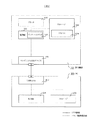
図2は、本発明で周辺機器100をコンポジットデバイスとしたシステムの構成を示している。一般にUSB機器において、コンポジット構成とは複数の機能部を内蔵するが、USBハブは内蔵しない構成をいう。 FIG. 2 shows a system configuration in which the peripheral device 100 is a composite device in the present invention. In general, in a USB device, a composite configuration refers to a configuration in which a plurality of functional units are incorporated, but a USB hub is not incorporated.
図2ではプリンタとストレージのコンポジット構成を示しているが、実施例1の場合と同様、イメージスキャナにストレージという構成、あるいはその両方、プリンタとイメージスキャナ、ストレージを搭載した複合機でも同様に本発明は実施できる。 FIG. 2 shows a composite configuration of a printer and a storage. Similarly to the case of the first embodiment, the present invention is similarly applied to a configuration in which an image scanner is configured to store, or both, or to a multi-function device having a printer, an image scanner, and a storage. Can be implemented.
本実施例の周辺機器100は、制御部101、プリンタ102、ストレージ103、ドライバ104、USBデバイス120からなり、制御部101以外の各部は制御部101にバス、制御線などで接続され、制御部101の制御を受ける。
The peripheral device 100 according to the present exemplary embodiment includes a
本実施例でも、制御部101のメモリ部の適当なアドレスにはインストールフラグ105が割り付けられている。インストールフラグ105は、後述のようにそのフラグの状態によって、USBハブ110とプリンタクラスUSBデバイス111との接続状態を変化させるために用いられる。
Also in this embodiment, the installation flag 105 is assigned to an appropriate address in the memory unit of the
インストールフラグ105は、”未インストール”と”インストール済み”の2つの状態を記憶し、工場出荷時は”未インストール”となっている。もちろん、ストレージ103にインストールフラグの状態を記録しておいてもよい。また、後述する制御プログラムは、たとえば制御部101のROM部に記録しておく。
The installation flag 105 stores two states of “not installed” and “installed”, and is “not installed” at the time of shipment from the factory. Of course, the status of the installation flag may be recorded in the
プリンタ102は、インクジェット方式など適当な記録方式のプリンタエンジンから構成される。
The
ストレージ103は、ROM、RAM、HDDなどから構成された記憶装置で、PC200のOS上でプリンタ102を動作させるためのドライバ104を記憶している。これは読み書き可能であっても読み込み専用であってもかまわないし、先述の制御部101のROM、RAMなどと共用してもかまわない。
The
ドライバ104は、PC200のOSで動作するデバイスドライバである。ドライバ104は、PC200にプリンタクラスUSBデバイス111を制御する機能と、後述するがPC200から周辺機器100に対してドライバのインストールが完了したことを伝える機能を提供する。また、ドライバ104には、ドライバ104自身をインストールするインストーラ、インストーラをPC200で自動実行する設定ファイルが含まれている。
The
USBデバイス120はUSBの規格を満たす。これとPC200はそれぞれ図のようにUSBで接続されている。本実施例でも、図中[H]をホスト側、[D]がデバイス側の接続を示す。本実施例ではホスト/デバイスの区別は図示の通りとするが、USBOnTheGoなど別の規格を用いる場合、ホスト/デバイスの組合せはこの通りでなくてもよい。
The
本実施例では、USBデバイス120は、ストレージクラスと、2つのデバイスとしての機能を切り替える形で有するコンポジットデバイスとして構成する。
In this embodiment, the
USBデバイス120の1つ目のデバイスクラスはストレージクラスで、図7のようなディスクリプタ、エンドポイントの構成で、ストレージクラスのディスクリプタをPC200に返したりデータ送受信でき、ストレージ103をホストからアクセスできる。
The first device class of the
USBデバイス120の2つ目のデバイスクラスは、周辺機器がプリンタであれば、図9のようにストレージクラスとプリンタクラスの複数のディスクリプタとインターフェースを持ったコンポジット構成のUSBデバイスとしての機能を有する。
If the peripheral device is a printer, the second device class of the
図7および図9に示したディスクリプタは後述のように切り換えて用いられる。すなわち、図7および図9に示したディスクリプタのうち、たとえばデバイスディスクリプタのベンダーID、プロダクトID、シリアルナンバーと、ストリングディスクリプタのプロダクト名などはUSBデバイスの構成により異なるものを用いる。たとえば、図7の構成と、図9の構成では、上記のディスクリプタにはそれぞれ違う文字列を用いる。また、当然ながら、図7の構成から図9の構成へUSBデバイスが切り替わった際には、PC200から見て全く別のデバイスとして認識されなければならない。
The descriptors shown in FIGS. 7 and 9 are switched and used as will be described later. That is, among the descriptors shown in FIGS. 7 and 9, for example, the vendor ID, product ID, serial number of the device descriptor, and the product name of the string descriptor are different depending on the configuration of the USB device. For example, in the configuration of FIG. 7 and the configuration of FIG. 9, different character strings are used for the descriptors. Of course, when the USB device is switched from the configuration of FIG. 7 to the configuration of FIG. 9, it must be recognized as a completely different device when viewed from the
もし、周辺機器100がさらにイメージスキャナをもつ複合機であれば、このイメージスキャナは、スチルイメージクラス、またはベンダークラスのインターフェースと各エンドポイントを持つデバイスクラスとして図9のコンポジット構成に追加することができる。 If the peripheral device 100 is a multifunction peripheral having an image scanner, the image scanner can be added to the composite configuration of FIG. 9 as a device class having a still image class or vendor class interface and each endpoint. it can.
本実施例では、PC200は、実施例1と同様に構成されているものとし、ここでは詳細な説明は省略するが、PC200は、USBホスト203を介して周辺機器100のUSBデバイス120と接続される。
In the present embodiment, the
次に上記構成における動作につき説明する。ここでは、まず周辺機器100をPC200に接続して動作可能になるまでの流れを説明する。
Next, the operation in the above configuration will be described. Here, the flow until the peripheral device 100 is connected to the
図6は、実施例1の図4に相当し、周辺機器100の内部処理の流れを示している。インストーラの動作は実施例1と同じで図5の通りとする。 FIG. 6 corresponds to FIG. 4 of the first embodiment and shows the flow of internal processing of the peripheral device 100. The operation of the installer is the same as that of the first embodiment and is as shown in FIG.
また図2ではPC200と周辺機器100は既にUSBケーブルで接続された状態を示しているが、以下では、周辺機器100が出荷され、ユーザが購入した直後の状態、すなわちPC200と周辺機器100がまだ接続されていない状態から説明する。以下では、まずユーザが周辺機器100をPC200と接続した時のおおまかな流れ、および図5のドライバ104のインストーラの制御を説明し、続いて図6の周辺機器100側の制御の流れを詳細に説明する。
2 shows a state in which the
周辺機器100の出荷直後の初期状態ではインストールフラグは”未インストール”である。制御部101によりインストールフラグ105の値が”未インストール”であることが確認されると(後述のステップS602)、USBデバイス120をストレージクラスのみの構成とする(後述のステップS603)。すなわち、制御部101の制御によりストレージ103(のみ)がUSBデバイス120のストレージクラスUSBデバイスとなっており、USBデバイス120に対するSCSIコマンドによってストレージ103にアクセスできるようになっている。
In the initial state immediately after the peripheral device 100 is shipped, the installation flag is “not installed”. When the
近年のOSでは、メモリカードリーダ、デジタルカメラなどの普及により、USBマス・ストレージクラスのドライバが同梱されているのが一般的である。また、USBハブのドライバについても同様である。本実施例のPC200のOSにおいても、このように一般的な(非コンポジットの)ストレージクラスドライバ、USBハブドライバがはじめからインストールされているものとする。ただし、コンポジット対応のストレージクラスドライバはまだ最新のOSにしか同梱されていないことが考えられるが、この点を考慮してコンポジット対応のストレージクラスドライバはドライバ104に含めておけばよい。
In recent OSs, a USB mass storage class driver is generally included with the spread of memory card readers, digital cameras, and the like. The same applies to the USB hub driver. Also in the OS of the
PC200のOSが非コンポジットのストレージクラスドライバのみしか有していない場合でも、上記のように初期状態ではUSBデバイス120をストレージクラスのみのUSBデバイスとして動作させれば問題なく後述の動作が可能となる。
Even when the OS of the
ここで周辺機器100とPC200がユーザによって接続すると、PC200のOSに既にインストール済みのマス・ストレージクラスのドライバが動作し、ストレージクラスUSBデバイスとなっているUSBデバイス120が認識され、マウントされる。
Here, when the peripheral device 100 and the
ここで、PC200のOSでは、周辺機器100のストレージ103がドライブの一つとしてマウントされるものとする。なお、ファイルにアクセスするパス名に「ドライブ」の概念を用いないOSも存在するが、そのようなOSのファイルシステムでは、ストレージ103はルートディレクトリから始まるディレクトリツリーの一部としてマウントされる。
Here, in the OS of the
このようにしてストレージ103内のドライバ104に含まれるインストーラが実行できるようになる。該インストーラを実行する手法の1つとしては、ユーザが取扱説明書などの記載に基づき、手動でストレージ103内のドライバ104に含まれるインストーラを起動する方法が考えられる。また、OSによっては、ドライブやメディアをファイルシステムにマウントした時に自動的に特定の名前の実行ファイルを起動できるものがあるが、このような機構を利用してインストーラを起動してもよい。これらのいずれかの方法によりインストーラが起動され、ドライバ104がPC200のストレージ202上にインストールされる。
In this way, the installer included in the
インストーラの動作フローは図5に示した通りである。すなわち、ステップS501でユーザにインストールの確認、ファイルのインストール場所などインストールに必要な情報があればユーザの入力を促す。ステップS502でドライバのインストールを行なう。本実施例の場合、ドライバ104は図9のコンポジット構成の定義ファイルと、コンポジット対応のプリンタクラスドライバ(あるいはさらにコンポジット対応のストレージドライバ)である。
The operation flow of the installer is as shown in FIG. That is, in step S501, if there is information necessary for installation, such as confirmation of installation and file installation location, the user is prompted to input. In step S502, the driver is installed. In this embodiment, the
ステップS503でドライバのインストールが完了したことをPC200から周辺機器100へ通知する。この通知の方法としては、既にマウントされているストレージクラスデバイスを用いる場合、特定のベンダリクエストを送る、特定のSCSIコマンドを送る、ストレージデバイスの特定のセクタに特定の値を書き込む、等が考えられる。また、USBデバイス120に対してベンダリクエストを送る方法も考えられる。
In step S503, the
上記いずれかの方法でドライバのインストール完了がPC200から通知される(後述のステップS605)と、周辺機器100ではインストールフラグ105をインストール済み状態とする(後述のステップS606)。さらに、PC200と周辺機器100とのUSB接続を、制御部101がUSBデバイス120を制御することによって、切断する(後述のステップS607)。なお、このとき、PC200と周辺機器100との物理的なUSBケーブルはつながったままである。
When the driver installation completion is notified from the
そして、コンポジットUSBデバイスの、ディスクリプタ、エンドポイント、インターフェースの構成を図7のものから図9のものに切り替える。その後、接続を切断し、ある程度の間隔を置いた後、PC200と周辺機器100との電気的な接続を再開する。
Then, the configuration of the descriptor, the endpoint, and the interface of the composite USB device is switched from that in FIG. 7 to that in FIG. Thereafter, the connection is disconnected and after a certain interval, the electrical connection between the
PC200では、先程まで接続されていたものとは別のストレージクラスとプリンタクラスの両方をそなえたコンポジットUSB機器が接続されたと認識する。すなわち、PC200は既にインストール済みのコンポジット対応のストレージクラスドライバと、プリンタクラスドライバをマウントする。
The
以上のようにして、ユーザが周辺機器100をPC200に接続するだけで、プリンタのドライバをPC200にインストールすることができる。
As described above, the printer driver can be installed in the
次に、図6の周辺機器100側の制御の流れをより詳細に説明する。 Next, the control flow on the peripheral device 100 side in FIG. 6 will be described in more detail.
図6の処理は周辺機器100のAC電源、ソフトスイッチ、ともにオン状態で開始され、まず、ステップS601で周辺機器内の初期化が行われる。 The processing in FIG. 6 is started when both the AC power supply and the soft switch of the peripheral device 100 are turned on. First, in the step S601, initialization in the peripheral device is performed.
ステップS602でインストールフラグをチェックする。先述の通り工場出荷時フラグは”未インストール”である。”未インストール”ならステップS603へ、”インストール済み”ではステップS610へ処理を進める。 In step S602, the installation flag is checked. As described above, the factory default flag is “not installed”. If “not installed”, the process proceeds to step S603. If “installed”, the process proceeds to step S610.
ステップS603では、USBデバイス120を図7のストレージクラスのみの構成とする。ステップS604では通常の周辺機器の待機状態となり、通常の周辺機器の動作はここで行なう。USBの各リクエストなどあれば応答し、ストレージクラスとなっているUSBデバイス120に対して各リクエストがあれば応答し、SCSIコマンドが来たら必要に応じてストレージ103をアクセスし応答する。
In step S603, the
同時にステップS605でインストール完了通知を待ち、PC200から通知が来たらステップS606へ処理を移す。
At the same time, an installation completion notification is waited in step S605, and when a notification is received from the
ステップS606においてインストールフラグ105を”インストール済み”にしてステップS607の処理へ進む。ステップS607では、制御部101がUSBデバイス120を制御することによって、PC200と周辺機器100とのUSB接続を電気的に切断する。このとき、PC200と周辺機器100との物理的なUSBケーブルはつながったままである。
In step S606, the installation flag 105 is set to “installed”, and the process proceeds to step S607. In step S <b> 607, the
さらに、コンポジットUSBデバイスの、ディスクリプタ、エンドポイント、インターフェースの構成を、図7のものから図9のものに切り替えた後、PC200と周辺機器100との電気的な接続を再接続してステップS611へ進む。ステップS610ではUSBデバイス120を図9のコンポジット構成とする。
Furthermore, after the configuration of the descriptor, the endpoint, and the interface of the composite USB device is switched from the one in FIG. 7 to the one in FIG. 9, the electrical connection between the
ステップS611では通常の周辺機器の待機状態となる。ステップS604と同様の処理に加えて、USBデバイス120の、プリンタクラスUSBインターフェースに対するUSBの各リクエストを返す。また、PC200からのプリントデータなども受け取りプリンタ102を制御してプリントしたり、PC200から要求があれば各ステータスを送ったりする。
In step S611, a normal peripheral device is in a standby state. In addition to the same processing as in step S604, each USB request for the printer class USB interface of the
ステップS612では、ユーザのインストールフラグ解除操作が周辺機器100の外部入力手段で行なわれていないかをチェックする。この解除操作は、たとえば液晶パネルとスイッチなどによって行なうものとする。あるいは、PC200側での適当なユーザ操作に応じて特定のUSBベンダリクエストを発生して解除操作を行なうようにしてもよい。
In step S612, it is checked whether or not the user's installation flag cancellation operation has been performed by the external input means of the peripheral device 100. This release operation is performed by, for example, a liquid crystal panel and a switch. Alternatively, the release operation may be performed by generating a specific USB vendor request in accordance with an appropriate user operation on the
通常、ユーザが周辺機器を購入してPC200に接続するだけであればこのようなインストールフラグ解除操作手順は必要ない。しかし、他のPCに接続する場合や、周辺機器100を他人に譲る場合などには、この解除操作を行なうことによってインストールフラグを工場出荷状態と同じ”未インストール”状態に戻すことができる。もし、インストールフラグ105の解除操作が行われたらステップS613へ、そうでなければステップS611で待機状態を続行する。ステップS613ではインストールフラグを”未インストール”状態に変更し、ステップS603へ処理を移す。
Normally, if the user only purchases a peripheral device and connects it to the
以上のようにして、本実施例によれば、PC200にドライバソフトウェアが未インストールである状態では、PC200がストレージ103のみにアクセスできるようUSBインターフェースが制御される。このため、従来のように誤まったドライバやダミードライバがインストールされてしまうことにより発生する問題を回避することができる。ドライバソフトウェアは、ユーザ操作や、デバイス接続時の自動処理によりストレージ手段に用意されているインストーラを実行することにより、容易かつ確実にインストールすることができる。すなわち、ユーザが周辺機器100をPC200に接続するだけで、ユーザの手をほとんど煩わせることなくプリンタのドライバをPC200にインストールすることができる。
As described above, according to this embodiment, the USB interface is controlled so that the
本発明は、ホスト装置にドライバソフトウェアをインストールして用いる必要がある種々の周辺装置、あるいはさらにこの周辺装置とホスト装置から成るシステムにおいて実施することができる。本発明を実施するためのソフトウェアは、周辺装置のROMなどのメモリ、本発明で用いるストレージ内に格納しておく他、ネットワークや、外部記憶媒体経由で周辺装置に供給、あるいはアップデートすることができる。 The present invention can be implemented in various peripheral devices that need to install and use driver software in the host device, or in a system that further includes the peripheral device and the host device. The software for carrying out the present invention can be stored in a memory such as a ROM of a peripheral device or a storage used in the present invention, and can be supplied or updated to the peripheral device via a network or an external storage medium. .
100 周辺機器
101 制御部
102 プリンタ
103 ストレージ
104 ドライバ
105 インストールフラグ
110 USBハブ
111 プリンタクラスUSBデバイス
112 ストレージクラスUSBデバイス
120 USBデバイス
200 PC
201 制御部
202 ストレージ
203 USBホスト
DESCRIPTION OF SYMBOLS 100
Claims (15)
前記ホスト装置が前記情報処理手段を用いるためにホスト装置上で動作するドライバソフトウェアおよび該ドライバソフトウェアのインストーラを格納したストレージ手段と、
前記情報処理手段、および前記ストレージ手段を前記ホスト装置と接続可能なインターフェース手段と、
前記ドライバソフトウェアが前記ホスト装置に対して未インストールであるか、またはインストール済みであるかのいずれかの値を記録するインストールフラグと、
前記インターフェース手段にホスト装置が接続された時、前記インストールフラグが前記未インストールを示す値となっていれば前記インストーラを読み出して実行すべく前記ホスト装置が前記ストレージ手段のみにアクセスできるよう前記インターフェース手段を制御し、一方、前記インストールフラグが前記インストール済みを示す値となっていれば前記ホスト装置が前記ストレージ手段および前記情報処理手段にアクセスできるよう前記インターフェース手段を制御する制御手段を有することを特徴とする情報処理装置。 Information processing means connected to the host device and performing predetermined information processing as a peripheral device;
Storage means for storing driver software operating on the host device in order for the host device to use the information processing means, and an installer of the driver software;
Interface means capable of connecting the information processing means and the storage means to the host device;
An installation flag for recording a value of whether the driver software is not installed or installed in the host device;
When the host device is connected to the interface unit, the interface unit is configured so that the host device can access only the storage unit to read and execute the installer if the installation flag is a value indicating the non-installation. On the other hand, if the installation flag is a value indicating that the installation has been completed, the host device has control means for controlling the interface means so that the storage means and the information processing means can be accessed. Information processing apparatus.
前記ドライバソフトウェアが前記ホスト装置に対して未インストールであるか、またはインストール済みであるかのいずれかの値を記録するインストールフラグを用い、
前記インターフェース手段にホスト装置が接続された時、前記インストールフラグが前記未インストールを示す値となっていれば前記インストーラを読み出して実行すべく前記ホスト装置が前記ストレージ手段のみにアクセスできるよう前記インターフェース手段を制御し、一方、前記インストールフラグが前記インストール済みを示す値となっていれば前記ホスト装置が前記ストレージ手段および前記情報処理手段にアクセスできるよう前記インターフェース手段を制御する制御過程を含むことを特徴とする情報処理装置の制御方法。 Information processing means connected to the host device for performing predetermined information processing as peripheral equipment, storage means for storing driver software operating on the host device so that the host device uses the information processing means, and an installer of the driver software And an information processing apparatus control method comprising: interface means capable of connecting the information processing means and the storage means to the host device;
Using an installation flag that records the value of whether the driver software is not installed or installed on the host device,
When the host device is connected to the interface unit, the interface unit is configured so that the host device can access only the storage unit to read and execute the installer if the installation flag is a value indicating the non-installation. On the other hand, if the installation flag is a value indicating the installation, the host device includes a control process for controlling the interface unit so that the storage unit and the information processing unit can be accessed. A method for controlling the information processing apparatus.
Priority Applications (3)
| Application Number | Priority Date | Filing Date | Title |
|---|---|---|---|
| JP2006322720A JP2008139916A (en) | 2006-11-30 | 2006-11-30 | Information processing apparatus, control method for information processing apparatus, and control program for information processing apparatus |
| US12/443,208 US8332843B2 (en) | 2006-11-30 | 2007-11-07 | Information processing apparatus and control method for installing driver software |
| PCT/JP2007/072046 WO2008065886A1 (en) | 2006-11-30 | 2007-11-07 | Information processing apparatus and control method for information processing apparatus |
Applications Claiming Priority (1)
| Application Number | Priority Date | Filing Date | Title |
|---|---|---|---|
| JP2006322720A JP2008139916A (en) | 2006-11-30 | 2006-11-30 | Information processing apparatus, control method for information processing apparatus, and control program for information processing apparatus |
Publications (2)
| Publication Number | Publication Date |
|---|---|
| JP2008139916A true JP2008139916A (en) | 2008-06-19 |
| JP2008139916A5 JP2008139916A5 (en) | 2010-01-21 |
Family
ID=39467680
Family Applications (1)
| Application Number | Title | Priority Date | Filing Date |
|---|---|---|---|
| JP2006322720A Pending JP2008139916A (en) | 2006-11-30 | 2006-11-30 | Information processing apparatus, control method for information processing apparatus, and control program for information processing apparatus |
Country Status (3)
| Country | Link |
|---|---|
| US (1) | US8332843B2 (en) |
| JP (1) | JP2008139916A (en) |
| WO (1) | WO2008065886A1 (en) |
Cited By (2)
| Publication number | Priority date | Publication date | Assignee | Title |
|---|---|---|---|---|
| JP2010117949A (en) * | 2008-11-13 | 2010-05-27 | Canon Inc | Information processor, method for controlling the same, and program |
| JP2014222507A (en) * | 2009-11-19 | 2014-11-27 | クアルコム,インコーポレイテッド | Virtual peripheral hub device and system |
Families Citing this family (11)
| Publication number | Priority date | Publication date | Assignee | Title |
|---|---|---|---|---|
| US8836960B1 (en) | 2007-01-03 | 2014-09-16 | Marvell International Ltd. | Storing device drivers in imaging devices |
| US8341306B1 (en) * | 2008-07-21 | 2012-12-25 | Marvell International Ltd. | Installation of a device driver and a filter driver |
| DE112008003970T5 (en) * | 2008-08-05 | 2011-05-26 | Hewlett-Packard Development Co., L.P., Houston | Method and device for custom software installation |
| JP2010152815A (en) * | 2008-12-26 | 2010-07-08 | Seiko Epson Corp | Information processor, information processing system, and control method of information processor |
| CN101887374B (en) * | 2010-06-12 | 2015-08-12 | 中兴通讯股份有限公司 | The method and system of installing terminal equipment |
| US8862787B2 (en) * | 2010-12-20 | 2014-10-14 | Intel Incorporation | Method and apparatus for integrating driver(s) of a portable device into the portable device |
| JP2014085857A (en) * | 2012-10-24 | 2014-05-12 | Alpine Electronics Inc | Electronic device, electronic device communication control method, electronic device communication control program, information terminal device and electronic system |
| TWI544337B (en) * | 2012-10-25 | 2016-08-01 | 緯創資通股份有限公司 | Dual-operating-system architecture for sharing usb devices, and method for sharing usb devices in a dual-operating-system architecture |
| JP6395380B2 (en) * | 2014-01-07 | 2018-09-26 | キヤノン株式会社 | Information processing apparatus, information processing method, and program |
| WO2018067139A1 (en) | 2016-10-05 | 2018-04-12 | Hewlett-Packard Development Company, L.P. | Usb device filtering |
| US20190034361A1 (en) * | 2017-07-28 | 2019-01-31 | Action Star Technology Co., Ltd. | Peripheral device controlling method by using storage device and storage device capable of controlling peripheral devices |
Citations (2)
| Publication number | Priority date | Publication date | Assignee | Title |
|---|---|---|---|---|
| JP2001256170A (en) * | 2000-03-13 | 2001-09-21 | Hitachi Ltd | Peripheral device and printer |
| JP2003114859A (en) * | 2001-10-05 | 2003-04-18 | Matsushita Electric Ind Co Ltd | Usb connector |
Family Cites Families (20)
| Publication number | Priority date | Publication date | Assignee | Title |
|---|---|---|---|---|
| US5367698A (en) * | 1991-10-31 | 1994-11-22 | Epoch Systems, Inc. | Network file migration system |
| US5963743A (en) * | 1997-08-29 | 1999-10-05 | Dell Usa, L.P. | Database for facilitating software installation and testing for a build-to-order computer system |
| US6167567A (en) * | 1998-05-05 | 2000-12-26 | 3Com Corporation | Technique for automatically updating software stored on a client computer in a networked client-server environment |
| US6775829B1 (en) * | 1998-06-04 | 2004-08-10 | Gateway, Inc. | Method for configuring software for a build to order system |
| US6493871B1 (en) * | 1999-09-16 | 2002-12-10 | Microsoft Corporation | Method and system for downloading updates for software installation |
| US6947171B1 (en) * | 1999-10-01 | 2005-09-20 | Seiko Epson Corporation | Multifunction printer, computer, printing system and recording medium |
| JP2001096868A (en) | 1999-10-01 | 2001-04-10 | Seiko Epson Corp | Compound printing machine, computer, printing system and recording medium |
| US6598223B1 (en) * | 1999-10-06 | 2003-07-22 | Dell Usa, L.P. | Method and system for installing and testing build-to-order components in a defined configuration computer system |
| US6823508B1 (en) * | 2000-04-27 | 2004-11-23 | Microsoft Corporation | Automatic computer program customization based on a user information store |
| US6671749B2 (en) * | 2001-03-07 | 2003-12-30 | Hewlett-Packard Development Company, L.P. | Peripheral driver installation method and system |
| US7150025B2 (en) * | 2001-08-31 | 2006-12-12 | Hewlett-Packard Development Company, L.P. | System and method for providing hardware driver installation |
| JP2003150530A (en) | 2001-11-16 | 2003-05-23 | Naltec Inc | Peripheral equipment and its control method |
| US6976252B2 (en) * | 2002-05-17 | 2005-12-13 | Hewlett-Packard Development Company, L.P. | Systems and methods for driver installation |
| US7886291B1 (en) * | 2003-06-11 | 2011-02-08 | Symantec Corporation | Layer typed prioritizing application layered systems |
| US8010961B1 (en) * | 2003-06-11 | 2011-08-30 | Symantec Corporation | Data layer prioritization in an application layered system |
| US7945897B1 (en) * | 2002-06-12 | 2011-05-17 | Symantec Corporation | Method and system for running an application in a clean operating environment using a layered computing system |
| US7228541B2 (en) * | 2003-01-17 | 2007-06-05 | National Instruments Corporation | Creation of application system installer |
| US7478385B2 (en) * | 2003-01-17 | 2009-01-13 | National Instruments Corporation | Installing software using programmatic component dependency analysis |
| US7503041B2 (en) * | 2004-07-01 | 2009-03-10 | International Business Machines Corporation | Apparatus, system, and method for delivery of software |
| KR101309784B1 (en) * | 2006-12-28 | 2013-09-23 | 삼성전자주식회사 | Host device for installing driver and driver install method thereof |
-
2006
- 2006-11-30 JP JP2006322720A patent/JP2008139916A/en active Pending
-
2007
- 2007-11-07 US US12/443,208 patent/US8332843B2/en active Active
- 2007-11-07 WO PCT/JP2007/072046 patent/WO2008065886A1/en active Application Filing
Patent Citations (2)
| Publication number | Priority date | Publication date | Assignee | Title |
|---|---|---|---|---|
| JP2001256170A (en) * | 2000-03-13 | 2001-09-21 | Hitachi Ltd | Peripheral device and printer |
| JP2003114859A (en) * | 2001-10-05 | 2003-04-18 | Matsushita Electric Ind Co Ltd | Usb connector |
Cited By (3)
| Publication number | Priority date | Publication date | Assignee | Title |
|---|---|---|---|---|
| JP2010117949A (en) * | 2008-11-13 | 2010-05-27 | Canon Inc | Information processor, method for controlling the same, and program |
| US8427659B2 (en) | 2008-11-13 | 2013-04-23 | Canon Kabushiki Kaisha | Information processing apparatus which can selectively operate as storage device or printer device, method of controlling same, recording medium and printer which can selectively operate as storage device or printer device |
| JP2014222507A (en) * | 2009-11-19 | 2014-11-27 | クアルコム,インコーポレイテッド | Virtual peripheral hub device and system |
Also Published As
| Publication number | Publication date |
|---|---|
| US8332843B2 (en) | 2012-12-11 |
| US20100031250A1 (en) | 2010-02-04 |
| WO2008065886A1 (en) | 2008-06-05 |
Similar Documents
| Publication | Publication Date | Title |
|---|---|---|
| JP2008139916A (en) | Information processing apparatus, control method for information processing apparatus, and control program for information processing apparatus | |
| JP5163408B2 (en) | Information processing device | |
| JP2004054896A (en) | Usb storage device and controller therefor | |
| KR100589521B1 (en) | Usb storage device and control device | |
| JP5314976B2 (en) | Printing apparatus and control method thereof | |
| JP5039331B2 (en) | Information processing apparatus, deletion method, and program | |
| US8179554B2 (en) | Printer, control method of a printer and computer-readable recording medium | |
| JP2006079634A (en) | Usb storage device and program | |
| JP2006079634A5 (en) | ||
| US20070150072A1 (en) | Method for controlling electronic apparatus, program for controlling electronic apparatus, electronic apparatus, and recording apparatus | |
| JP5596376B2 (en) | Peripheral device | |
| JP5241439B2 (en) | Information processing apparatus, control method thereof, and program | |
| JP2004171536A (en) | Usb storage device and program | |
| US7827332B2 (en) | Portable storage medium | |
| JP2005115427A (en) | Peripheral device locally connected to computer | |
| JP2006293638A (en) | Information processor and peripheral equipment | |
| JP4551643B2 (en) | USB printer and USB scanner | |
| JP2004362593A (en) | Printer memory | |
| JP2004302870A (en) | Write-protect method for media reader/writer | |
| JP2011107944A (en) | Storage equipment | |
| JP2009100103A (en) | Printing device | |
| JP2005038297A (en) | Installation method of device driver, and system used for it | |
| US20100033747A1 (en) | Image forming device, image forming system and computer readable medium for install | |
| JP2004017624A (en) | Printer, printing system, and record medium | |
| JP4242798B2 (en) | USB storage device and control device thereof |
Legal Events
| Date | Code | Title | Description |
|---|---|---|---|
| A521 | Request for written amendment filed |
Free format text: JAPANESE INTERMEDIATE CODE: A523 Effective date: 20091130 |
|
| A621 | Written request for application examination |
Free format text: JAPANESE INTERMEDIATE CODE: A621 Effective date: 20091130 |
|
| RD04 | Notification of resignation of power of attorney |
Free format text: JAPANESE INTERMEDIATE CODE: A7424 Effective date: 20100201 |
|
| RD01 | Notification of change of attorney |
Free format text: JAPANESE INTERMEDIATE CODE: A7421 Effective date: 20100630 |
|
| A131 | Notification of reasons for refusal |
Free format text: JAPANESE INTERMEDIATE CODE: A131 Effective date: 20110920 |
|
| A02 | Decision of refusal |
Free format text: JAPANESE INTERMEDIATE CODE: A02 Effective date: 20120207 |