JP2004321608A - Endoscope system - Google Patents
Endoscope system Download PDFInfo
- Publication number
- JP2004321608A JP2004321608A JP2003122824A JP2003122824A JP2004321608A JP 2004321608 A JP2004321608 A JP 2004321608A JP 2003122824 A JP2003122824 A JP 2003122824A JP 2003122824 A JP2003122824 A JP 2003122824A JP 2004321608 A JP2004321608 A JP 2004321608A
- Authority
- JP
- Japan
- Prior art keywords
- connector
- light source
- circuit
- signal
- endoscope
- Prior art date
- Legal status (The legal status is an assumption and is not a legal conclusion. Google has not performed a legal analysis and makes no representation as to the accuracy of the status listed.)
- Pending
Links
Images


Landscapes
- Endoscopes (AREA)
- Instruments For Viewing The Inside Of Hollow Bodies (AREA)
Abstract
Description
【0001】
【発明の属する技術分野】
本発明は既存のコネクタ本体を有する内視鏡とも互換性を確保した内視鏡システムに関する。
【0002】
【従来の技術】
近年、細長の挿入部を体腔内に挿入することによって、切開を必要とすることなく体腔内深部の被写体を観察したり、必要に応じて処置具を用いて治療処置のできる内視鏡が広く用いられている。
【0003】
最近では、前記挿入部先端あるいは後端にCCD等の撮像素子を備え、この撮像素子により体腔内被写体の撮像観察を行う電子内視鏡を採用した内視鏡システムは、画像の記録等が容易に行えるため、広く普及している。
このような内視鏡システムの従来例として、例えば特開2002−34912号公報に開示されたものがある。
【0004】
この従来例は、光源装置と、撮像素子に対する信号処理を行う信号処理装置としてのプロセッサとが別体となっている。
そして、電子内視鏡及び光学式内視鏡にテレビカメラを装着したものを光源装置のコネクタ受けに接続可能とするコネクタを採用することにより、電子内視鏡及び光学式内視鏡にテレビカメラを装着した(テレビカメラ装着方式の内視鏡)のいずれでも使用できるようにしている。
【0005】
【特許文献1】
特開2002−34912号公報
【0006】
【発明が解決しようとする課題】
しかし、上記従来例では、光源装置に接続可能なコネクタを備えた内視鏡にのみしか対応できない。このため、例えばコネクタ本体から光源コネクタと電気コネクタとが異なる方向に設けられた既存の電子内視鏡の場合には使用できない欠点がある。
つまり、電気コネクタが光源装置に接続される場合の内視鏡の場合での使用に制約される欠点がある。
【0007】
(発明の目的)
本発明は、上述した点に鑑みてなされたもので、電気コネクタが光源コネクタと同じ方向に設けられ、光源装置に接続可能な内視鏡と、電気コネクタが光源コネクタと異なる方向に設けられてプロセッサ等の外部装置に接続可能な内視鏡とのいずれにおいても使用可能とする内視鏡システムを提供することを目的とする。
【0008】
【課題を解決するための手段】
被写体へ照射する照明光を発光する光源を備えた光源装置と、
前記光源が発光した前記照明光が入射される所定の形状を有する第1の光源コネクタと、
前記第1の光源コネクタを所定の方向へ延出させた第1のコネクタ本体を備えた第1の内視鏡と、
前記第1の光源コネクタと同様の形状を有し、前記光源が発光した前記照明光が入射される第2の光源コネクタと、
前記第2の光源コネクタを所定の方向へ延出させた第2のコネクタ本体を備えた第2の内視鏡と、
前記第1及び第2の光源コネクタを前記光源装置に選択的に接続することで、接続された光源コネクタを前記光源装置と光学的に接続する前記光源装置に設けた光源コネクタ受けと、
前記第1の内視鏡が有する所定の機能を実行するための動作をする前記第1の内視鏡に設けられた第1の電気部品と、
前記第1の内視鏡と同じ所定の機能を実行するための動作をする前記第2の内視鏡に設けられた第2の電気部品と、
前記第1のコネクタ本体から前記第1の光源コネクタと異なる方向へ延出させて設けられ、前記第1の電気部品と電気的に接続された第1の電気コネクタと、
前記第1の電気コネクタを前記光源装置と別体の外部装置に接続するための前記外部装置に設けられた第1の電気コネクタ受けと、
前記第2のコネクタ本体から前記第2の光源コネクタと同一方向へ延出させて設けられ、前記第2の電気部品と電気的に接続された第2の電気コネクタと、
前記第2の光源コネクタの前記光源コネクタ受けとの接続に伴って前記第2の電気コネクタを前記光源装置に接続するための前記光源装置に設けられた第2の電気コネクタ受けと、
前記第1の電気コネクタ受けに接続された前記第1の電気コネクタを介して前記第1の電気部品との間で前記第1の電気部品の機能に関する信号を送信又は受信する前記外部装置に設けられた第1の電気回路と、
前記第2の光源コネクタの前記光源コネクタ受けとの接続に応じて、前記第2の電気コネクタ受けに接続された前記第2の電気コネクタを介して前記第2の電気部品との間で前記第2の電気部品の機能に関する信号を送信又は受信する前記光源装置に設けられた第2の電気回路と、
を具備することによって、電気コネクタが光源コネクタと異なる方向に設けられた第2のコネクタ本体を有する第1の内視鏡と、電気コネクタが光源コネクタと同じ方向に設けられた第2の内視鏡とのいずれにおいても使用可能にしている。
【0009】
【発明の実施の形態】
以下、図面を参照して本発明の実施の形態を説明する。
(第1の実施の形態)
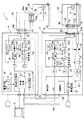
図1及び図2は本発明の第1の実施の形態に係り、図1は第1の実施の形態の内視鏡システムの全体構成を示し、図2は光源装置及びプロセッサのコネクタ受けに第1タイプのコネクタ及び第2タイプのコネクタを接続する場合の接続部周辺部を示す。
【0010】
図1に示すように本発明の第1の実施の形態の内視鏡システム1は、形状が異なる第1及び第2のコネクタ本体11A及び11B(図2参照)をそれぞれ有する第1の内視鏡2A及び第2の内視鏡2Bと、接続される第1の内視鏡2A及び第2の内視鏡2Bに照明光を供給する光源装置3と、この光源装置3と別体の外部装置であり、画像処理を行うプロセッサ4と、このプロセッサ4から出力される映像信号が入力されることにより、映像信号に対応する画像を表示するモニタ5とから構成される。
【0011】
第1及び第2の内視鏡2A及び2Bは、基本的には、コネクタ本体形状が異なっているのみである。
第1の内視鏡2A及び第2の内視鏡2Bとも、体腔内に挿入される細長の挿入部と、この挿入部の後端に設けられた操作部と、この操作部の側部から延出されたユニバーサルコード8(図2参照)とからなり、このユニバーサルコード8の端部には図2に示すように第1及び第2のコネクタ本体11A及び11Bがそれぞれ設けられている。
【0012】
第1の内視鏡2Aは図2(A)にも示すように、この第1のコネクタ本体11Aにはその前端面に光源用コネクタ12と、電気コネクタ部13Aとが隣接して設けてある。つまり、第1のコネクタ本体11Aにはその前端面に光源用コネクタ12と、電気コネクタ13Aとが同じ前方向に突出(延出)するように設けられている。
【0013】
これに対して第2の内視鏡2Bでは、図2(B)にも示すように、この第2のコネクタ本体11Bにはその前端面に光源用コネクタ12が設けてあり、その側方に電気コネクタ13Bが設けてある。つまり、第2のコネクタ本体11Bには光源用コネクタ12が突出(延出)される方向と異なる方向に電気コネクタ13Bが突出されるように設けられている。
【0014】
なお、第1の内視鏡2A及び第2の内視鏡2Bともに、光源用コネクタ12は同じ構造で、ライトガイドコネクタ14及び流体用コネクタ15とからなる。 図1に示すように第1の内視鏡2A及び第2の内視鏡2Bとも、内部にライトガイド16が挿通されており、コネクタ本体11A或いは11B(の光源用コネクタ12)を光源装置3に接続することにより、光源装置3からライトガイドコネクタ14のライトガイド16の端面に照明光が供給され、このライトガイド16により伝送されて挿入部の先端部の照明窓に固定されたライトガイド先端面から照明光を出射し、体腔内の患部等の被写体を照明する。
【0015】
照明窓に隣接して設けられた観察窓には図示しない対物レンズが取り付けられており、照明された被写体の光学像を結ぶ。この結像位置には内視鏡2A及び2Bが有する所定の機能、具体的には撮像機能を持つ電気部品として固体撮像素子として、例えば電荷結合素子(CCDと略記)17が配置されており、光学像を光電変換する。
【0016】
光源装置3は商用電源から直流の電源を生成する電源回路21と、この電源回路21で生成された直流電源により照明光を生成する光源回路22と、第1の内視鏡2Aに内蔵された(第1の電気部品としての)CCD17を駆動すると共に、このCCD17で撮像された撮像信号に対する信号処理の前処理機能を有する患者基板23とを内蔵している。
【0017】
また、この光源装置3の前面には図2に示すように光源用コネクタ12が着脱可能に接続される光源用コネクタ受け25と、電気コネクタ13Aが着脱可能に接続される電気コネクタ受け26とが設けてある。つまり、第1の内視鏡2Aのコネクタ本体11Aが着脱可能に接続されるコネクタ本体受け27Aが設けてある。
【0018】
光源装置3における電源回路21は絶縁トランス等のアイソレーション回路(図1では「F」と略記)を有し、商用電源に接続されるプラグを設けた商用電源ケーブルを介して供給される商用電源と絶縁された2次回路用の直流電源を光源回路22に供給する。
【0019】
そして、光源回路22を駆動してキセノンランプ等のランプ31を点灯する。このランプ31の光は集光レンズ32により集光され、絞り33を経て光源用コネクタ受け25(のライトガイドコネクタ受け)に装着されるライトガイドコネクタ14に照明光を供給する。
また、電源回路21は、2次回路とも絶縁された絶縁トランス等のアイソレーション回路(図1では「F」と略記)を経て生成された患者回路用の直流電源を患者基板(或いは患者回路)23に供給する。
【0020】
この患者基板23は基準となるクロックCLKを生成するクロック発生回路41と、このクロックCLKにより各種のタイミング信号を発生するタイミング発生回路42と、このタイミング発生回路42からのタイミング信号に同期してCCD17を駆動するCCDドライブ信号(駆動信号)を生成するCCDドライブ回路43と、このCCDドライブ信号が印加された(第1の内視鏡2Aに内蔵された)CCD17から出力される撮像信号を低雑音で増幅するプリアンプ44と、このプリアンプ44で増幅された信号から信号成分を抽出してベースバンドの信号を出力する相関二重サンプリング(CDSと略記)回路45と、CDS回路45でベースバンド変換された信号をA/D変換するA/D変換回路46と、CDS回路45を適切な位相で動作させるための位相制御(PLLと略記)回路47と、上記絞り33の開口を調整することにより、モニタ5に表示される内視鏡画像の明るさを適切なレベルに自動調光する調光信号を生成する調光回路48とを有する。
【0021】
クロック発生回路41は水晶発振器等を用いて生成した発振出力をN分周(図1では1/Nで略記)等して基準のクロックCLKを生成し、タイミング発生回路42に供給すると共に、フォトカプラ等のアイソレーション回路(図1ではこれも「F」で略記)を介して光源装置3のリアパネルに設けた通信ケーブル接続コネクタ49に接続される通信ケーブル50を介してプロセッサ4側にも供給する。
【0022】
タイミング発生回路42はCCDドライブ回路43、CDS回路45、A/D変換回路46及び調光回路48にその動作に必要なタイミング信号を供給する。
CCDドライブ回路43は電気コネクタ受け26のCCDドライブ信号出力端子(駆動信号出力端子)T1に接続され、この電気コネクタ受け26に接続される第1の内視鏡2Aの電気コネクタ13AのCCDドライブ信号入力端子(駆動信号入力端子)T1aを経て(この端子T1aに接続された信号線を介して)CCD17にCCDドライブ信号が印加される。
【0023】
また、プリアンプ44の信号入力端は電気コネクタ受け26の撮像信号入力端子T2に接続されている。そして、この電気コネクタ受け26に第1の内視鏡2Aの電気コネクタ13Aが接続されると、CCD17の出力端子と電気的に接続され、電気コネクタ13Aに設けた撮像信号出力端子T2a及びこの撮像信号出力端子T2aに接続される撮像信号入力端子T2を経て(CCD17の)撮像信号がプリアンプ44に入力される。
【0024】
このプリアンプ44で増幅された出力信号はCDS回路45の他に、PLL回路47にも供給される。このPLL回路47はCCD17のドライブ信号線及び出力信号線により、実際に位相ずれが発生した撮像信号中のドライブ信号成分をプリアンプ44からの出力信号により受け、CDS回路45による信号成分抽出のサンプリングパルスのタイミング(位相)調整を行う。
【0025】
また、このCDS回路45の出力信号は調光回路48にも供給され、調光回路48は例えば数フレーム分の周期等で信号成分を積分するなどして、基準の明るさレベルと比較し、その場合の誤差信号を調光信号として絞り33の開口量を調整する。そして、常時適切な明るさの画像が得られるように照明光量を自動調整する。
【0026】
一方、(光源装置3と別体の外部装置としての)プロセッサ4は、商用電源から直流の電源を生成する電源回路51と、この電源回路51で生成された直流電源により画像として表示するための映像信号を生成する処理を行う映像処理基板52と、第2の内視鏡2BのCCD17を駆動すると共に、そのCCD17で撮像された撮像信号に対する前処理を行う患者基板(或いは患者回路)53とを内蔵している。
【0027】
また、このプロセッサ4の前面には図2(B)に示すように電気コネクタ13Bにその一端の電気コネクタ54aが着脱自在に接続される電気ケーブル54の他端の電気コネクタ54bが着脱可能に接続される電気コネクタ受け55が設けてある。
【0028】
また、このプロセッサ4のリアパネルには光源装置3のコネクタ49に一端が接続される通信ケーブル50の他端が接続されるコネクタ56が設けてあり、光源装置3側からクロックCLK、デジタルの映像信号が入力されると共に、プロセッサ4側で生成した調光信号を光源装置3側に送ることができるようにしている。
【0029】
電源回路51は絶縁トランス等のアイソレーション回路(図1では「F」と略記)を有し、商用電源に接続されるプラグを設けた商用電源ケーブルを介して供給される商用電源と絶縁された2次回路用の直流電源を映像処理基板52に供給する。
【0030】
また、電源回路51は、2次回路とも絶縁された絶縁トランス等のアイソレーション回路(図1では「F」と略記)を経て生成された患者回路用の直流電源を患者基板53に供給する。
【0031】
この患者基板53は光源装置3内に設けた患者基板23におけるクロック発生回路41を除けば同じ回路を備えている。つまりこの患者基板53は、タイミング発生回路42、CCDドライブ回路43、プリアンプ44、CDS回路45、A/D変換回路46、PLL回路47及び調光回路48とから構成される。
【0032】
この患者基板53のタイミング発生回路42には、光源装置3から通信ケーブル50が接続されるコネクタ56を経て入力されるクロックCLKがアイソレーション回路を介して入力される。そして、このタイミング発生回路42は、このクロックCLKに同期して各種のタイミング信号を発生する。
また、このタイミング発生回路42はCCDドライブ回路43、CDS回路45、A/D変換回路46及び調光回路48にその動作に必要なタイミング信号を供給する。
【0033】
CCDドライブ回路43は電気コネクタ受け55のCCDドライブ信号出力端子T1′に接続されており、図2(B)に示すように第2の内視鏡2Bの電気コネクタ13Bが電気ケーブル54を介して接続されると、この電気ケーブル54を介して第2の内視鏡2Bの電気コネクタ13Bに設けたCCDドライブ信号入力端子T1b(図1参照)を経てCCD17にはCCDドライブ信号が供給印加される。
【0034】
また、プリアンプ44の信号入力端も電気コネクタ受け55に設けた撮像信号入力端子T2′に接続されている。そして、第2の内視鏡2Bに内蔵されたCCD17からの撮像信号が撮像信号出力端子T2bから電気ケーブル54を経て、さらに撮像信号入力端子T2′を経てプリアンプ44に入力される。
【0035】
この患者基板53においても、光源装置3の場合で説明したのと同様にCCD17の駆動を行うと共に、CCD17の出力信号に対して同様の信号処理を行う。そして、A/D変換回路46を経てデジタルの映像信号が生成され、このデジタルの映像信号はアイソレーション回路を経て映像処理基板52に形成された映像処理回路57に入力される。
【0036】
この映像処理回路57には通信ケーブル50を経て光源装置3側で生成された場合のデジタルの映像信号も入力されるようになっている。この映像処理回路57は色分離、γ補正、輪郭強調等の処理を行った後、エンコーダにより各種方式の映像信号を生成し、モニタ5に出力する。
【0037】
また、この映像処理基板52には、映像処理回路57における各種動作を行う際のタイミング信号を生成するタイミング発生回路58が設けてあり、このタイミング発生回路58で生成したタイミング信号(より具体的には映像処理制御信号を)映像処理回路57に供給する。
このタイミング発生回路58には光源装置3側で生成したクロックCLKが通信ケーブル50を介して供給される。
【0038】
このような構成による本実施の形態の内視鏡システム1では、光源装置3とプロセッサ4との両方に、CCD駆動を行うCCDドライブ回路43と、CCD出力信号に対する前処理を行うプリアンプ44、CDS回路45、A/D変換回路46とを設けることにより、第1の内視鏡2Aでも第2の内視鏡2Bとのいずれの内視鏡でも使用できるようにしている。
【0039】
つまり、既存のコネクタ本体11Bを有する第2の内視鏡2Bを使用する場合には図2(B)に示すように光源用コネクタ12は光源装置3に接続するが、電気コネクタ13Bは電気ケーブル54を経てプロセッサ4の電気コネクタ受け55に接続することにより、プロセッサ4内部に設けた患者基板53のCCDドライブ回路43からのCCDドライブ信号で第2の内視鏡2Bに内蔵されたCCD17を駆動する。
【0040】
また、そのCCD17で撮像された撮像信号はプロセッサ4内部に設けた患者基板53のプリアンプ44で増幅し、CDS回路45で信号成分を抽出してベースバンドの信号に変換し、さらにA/D変換回路46でデジタルの映像信号に変換した後、アイソレーション回路を経て映像処理回路57に出力し、映像処理回路57により標準的な映像信号に変換された後、モニタ5に出力される。このモニタ5の表示面にはCCD17で撮像された体腔内の患部等の被写体の画像が内視鏡画像として表示され、術者はモニタ5に表示される内視鏡画像を観察して内視鏡検査、診断等を行うことができる。
【0041】
一方、既存のコネクタ本体11Bとは異なり、光源用コネクタ12と同じ前端に電気コネクタ13Aが設けられたコネクタ本体11Aを設けた第1の内視鏡2Aの場合には、このコネクタ本体11Aが着脱自在となるコネクタ受け27Aを設けた光源装置3の内部に設けた患者基板23に形成されたCCDドライブ回路43からのCCDドライブ信号により、上記プロセッサ4の患者基板53の場合と同様にCCD駆動を行う(但し、この場合には第1の内視鏡2Aに内蔵されたCCD17であるが)。
【0042】
また、CCD17から出力された撮像信号は患者基板23に形成されたプリアンプ44等を経てさらにA/D変換回路46でデジタルの映像信号に変換される。
【0043】
そして、アイソレーション回路、通信ケーブル50を経てプロセッサ4内の映像処理回路57に入力され、この映像処理回路57により標準的な映像信号に変換された後、モニタ5に出力される。
【0044】
このように本実施の形態によれば、既存のコネクタ本体11Bを備えた内視鏡2Bの場合でも、既存のコネクタ本体11Bとは異なるコネクタ本体11Aを備えた第1の内視鏡2Aでも同様に内視鏡検査、診断を行うことができる内視鏡システムを実現できる。
【0045】
換言すると、本実施の形態によれば、既存のコネクタ本体11Bを備えた内視鏡2Bで使用できると共に、既存のコネクタ本体11Bとは形状が異なるコネクタ本体11Aを備えた内視鏡2Aの場合のいずれでも使用できる内視鏡システム1を実現できる。
【0046】
従って、既存の内視鏡2Bでも引き続いて内視鏡検査に有効に利用できる互換性を確保でき、しかも既存のコネクタ本体11Bとは形状が異なる新しいコネクタ本体11Aを備えた内視鏡2Aでも内視鏡検査に有効に利用できるシステムを実現できる。
【0047】
(第2の実施の形態)
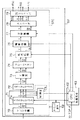
次に本発明の第2の実施の形態を図3を参照して説明する。図3は本発明の第2の実施の形態の内視鏡システム1Bの構成を示す。
この内視鏡システム1Bは、図1の内視鏡システム1において、光源装置3側のタイミング発生回路42の機能の他に、さらに映像処理回路57を制御するタイミング信号(より具体的には映像処理制御信号)も生成するタイミング発生回路42Bにしている。
【0048】
そして、この映像処理制御信号をアイソレーション回路を介して通信ケーブル50を経てプロセッサ4の映像処理回路57に供給するようにしている。このため、本実施形態におけるプロセッサ4では、図1の映像処理基板52に設けていたタイミング発生回路58を設けない構成の映像処理基板52Bにしている。
その他の構成は第1の実施の形態と同様の構成である。
【0049】
本実施の形態は第1の実施の形態における映像処理基板52に設けていたタイミング発生回路58で映像処理制御信号を光源装置3のタイミング発生回路42で発生するようにしたことを除けば同様の作用となる。
本実施の形態は、第1の実施の形態と同様の効果を有すると共に、プロセッサ4側のタイミング発生回路58を不用にでき、その回路規模を低減化できる効果がある。
【0050】
(第3の実施の形態)
次に本発明の第2の実施の形態を図4及び図5を参照して説明する。図4は本発明の第3の実施の形態の内視鏡システム1Cの構成を示す。本実施の形態は、さらに異なる画素数等を備えた内視鏡に対応できるようにしたものである。
第1及び第2の実施の形態では、内視鏡2A及び2Bは同じ画素数のCCD17を採用していたが、本実施の形態では異なる画素数等のCCD17a、17bを備えた内視鏡2A及び2Bに対応できるようにしたものである。
【0051】
このため、図4に示す内視鏡システム1Cでは、内視鏡2A及び2Bには、各内視鏡2I(I=A,B)に内蔵されたCCD17i(i=a、b)の他に、そのCCD17iを駆動する情報と適切に信号処理する場合の情報としてのスコープIDデータを格納したリードオンリメモリ(ROM)等で形成されたスコープID回路61iを内蔵している。
【0052】
そして、スコープID回路61aは信号線によりコネクタ本体11A(の電気コネクタ26)の端子T3aに接続されている。また、スコープID回路61bは信号線により(コネクタ本体11Bの)電気コネクタ13Bの端子T3bに接続されている。
【0053】
また、本実施の形態におけるプロセッサ4Cは、図1のプロセッサ4において、さらにスコープID回路61iからスコープIDデータを読み取り、対応する制御を行う制御回路として、CPU62を備えた制御基板63を設けている。
【0054】
このCPU62は、通信ケーブル50のスコープIDデータの伝送線を介して光源装置3CのスコープIDデータ端子と接続され、このスコープIDデータ端子は光源装置3C内に設けたアイソレーション回路を介してコネクタ受け27A(の電気コネクタ受け26)の端子T3に接続されている。
【0055】
そして、このコネクタ受け27Aに着脱自在のコネクタ本体11Aを設けた内視鏡2Aが接続されると、CPU62はその内視鏡2Aに内蔵したスコープID回路61aと電気的に接続され、それに書き込まれたスコープIDデータを読み取ることができる。
【0056】
また、このCPU62は、プロセッサ4C内に設けたアイソレーション回路を介してコネクタ受け55の端子T3′に接続されている。
そして、このコネクタ受け55に着脱自在の電気コネクタ54bを設けた電気ケーブル54を介して内視鏡2Bが接続されると、CPU62はその内視鏡2Bに内蔵したスコープID回路61bと電気的に接続され、それに書き込まれたスコープIDデータを読み取ることができる。
【0057】
また、このCPU62は、このプロセッサ4C内に設けたアイソレーション回路を介してタイミング発生回路42、CCDドライブ回路43及びプリアンプ44と接続され、CPU62はスコープID回路61bから読み取たスコープIDデータによりCCD17bを駆動する場合のタイミング制御等や増幅等の制御を行う。
【0058】
同様に、このCPU62は、通信ケーブル50の制御信号の伝送線を介して光源装置3Cと接続され、この光源装置3C内でさらにアイソレーション回路を介して患者基板23のタイミング発生回路42、CCDドライブ回路43及びプリアンプ44と接続され、CPU62はスコープID回路61aから読み取たスコープIDデータによりCCD17aを駆動する場合のタイミング制御等や増幅等の制御を行う。
【0059】
また、このCPU62は、プロセッサ4C内のタイミング発生回路58にも、スコープID回路61a或いは61bから読み取ったスコープIDデータを送り、タイミング発生回路58はこのIDデータにより、映像処理回路57Cで映像処理する映像処理制御信号をCCD17a或いは17bに適したものを生成する。
【0060】
つまり、第1及び第2の実施の形態では、内視鏡2A及び2Bには同じ画素数のCCD17であったので、タイミング発生回路58はそのCCD17に対応した映像制御信号を映像処理回路57に送っていたが、本実施の形態では例えば画素数が異なるCCD17a、17bであるので、信号処理するタイミングやパラメータを画素数等に応じて適切な設定状態で行えるようにしている。
また、本実施の形態における図4では、内視鏡2A及び2Bに内蔵されたCCD17a及び17bとスコープID回路61a及び61bに動作用電源を供給する給電線及び端子等を示している。
【0061】
図5は映像処理回路57Cの回路構成を示す。
図5に示すように(患者基板23或いは53から)出力されるデジタルの映像信号はY/C分離回路70に入力され、輝度信号Yと色差信号CB/CRに分離された後、RGBマトリックス回路71を構成するRGBマトリックス71aによりRGB信号に変換される。
【0062】
このRGB信号はカラーマトリックス回路72に入力されると共に、ホワイトバランス検波回路(図5中ではWB検波と略記)71bに入力される。ホワイトバランス検波回路71bでは、ホワイトバランスさせるために、RGB信号の輝度レベルを検波し、検波した信号をCPU62に出力する。
【0063】
そして、CPU62はその検波された信号により、RGBマトリックス71aでRGB信号に変換する係数等を調整して、ホワイトバランスするように調整(制御)する。
【0064】
また、このCPU62には、スコープIDデータが入力され、このスコープIDデータにより例えばスコープIDデータを読み出した内視鏡2Iに内蔵されている実際のCCD17iに対応したものでRGBマトリックス71aによるRGB信号の変換を制御する。また、タイミング発生回路58の制御を行う。
タイミング発生回路58は、入力されたスコープIDデータにより、対応する内視鏡2Iに搭載されているCCD17iの画素数等に応じた適切な信号処理タイミング信号を映像処理回路57Cの各プロセスに供給する。
【0065】
カラーマトリックス回路72では、RGB信号から再び輝度信号Yと色差信号CB/CRに変換し、γ補正回路73に出力する。このγ補正回路73でγ補正された信号はフレームメモリ(或いはフィールドメモリ)74により、例えば1フレーム分の信号データが格納される。
【0066】
フレームメモリ74から所定のタイミングで読み出された信号は拡大処理回路75に入力され、拡大処理がされる。この場合、CPU62はスコープIDデータにより、実際のCCD17iに対応した拡大処理を行うように制御する。つまり、画素数が異なる場合にも同じ拡大率で拡大処理すると、表示サイズが画素数等により変化してしまうので、画素数等に応じて適宜の拡大率で拡大処理を行う。
【0067】
また、この拡大処理された信号における輝度信号は輪郭強調回路76で輪郭強調された後、文字重畳回路77に入力され、また色差信号CB/CRは輪郭強調回路76を通さないで文字重畳回路77に入力される。
CPU62は輪郭強調回路76で輪郭強調する場合、やはりスコープIDデータにより、実際のCCD17iに対応して輪郭強調量を制御する。
【0068】
文字重畳回路77により、CCD17iの内視鏡画像に相当する映像信号に文字情報が重畳される。この場合にも、CPU62はやはりスコープIDデータにより、実際のCCD17iの画素数等に対応して適切な位置に文字情報が重畳されるように制御する。
【0069】
この文字重畳回路77から出力される信号はエンコーダ78に入力され、D/A変換と共に、各種の信号形態の映像信号が生成される。例えばNTSC方式、RGB方式、Y/C分離の映像信号が生成され、75Ωドライバ79を経てモニタ5に出力されるようになっている。
その他は第1の実施の形態と同様である。
【0070】
本実施の形態によれば、第1の実施の形態の作用効果の他に、内視鏡2A或いは2Bに実際に内蔵されているCCD17iの画素数や特性等が異なるようような場合においても、その内視鏡2Iに内蔵されたスコープID回路61iからスコープIDデータを読み出すことにより、そのCCD17iに適した駆動や信号処理を行うことができる。
つまり、本実施の形態によれば、第1の実施の形態の効果の他に、さらに画素数や特性等が異なる撮像素子を内蔵した種類が異なる内視鏡の場合にも対応ができる効果がある。
【0071】
次に図6を参照して変形例の内視鏡システム1Dを説明する。この内視鏡システム1Dは、図4の内視鏡システム1Cにおいて、内視鏡2A及び2BにはスコープID回路61a、61bの代わりに、例えばディップスイッチ81a、81bを設けて、ほぼ同様の機能を行えるようにしている。
【0072】
つまり、以下に説明するようにディップスイッチ81a、81bのスイッチ設定により、CCD識別信号を発生し、そのCCD識別信号でCCD17iの駆動や信号処理を制御するようにしている。そして、図4のプロセッサ4CにおけるCPU基板63を不用にしたプロセッサ4Dで済む構成にしている。
【0073】
ディップスイッチ81iは複数のスイッチS(図6では符号Sは1つのみに付けている)からなり、複数のスイッチSの一端は電源端子にそれぞれ接続された抵抗R(図6では符号Rは1つのみに付けている)と直列に接続され、他端はグランドに接続されている。そして、抵抗Rと接続されたスイッチSの一端がコネクタ本体11A(の電気コネクタ13A)の端子にそれぞれ接続されている。
【0074】
そして、スイッチSのオンオフの設定により、その内視鏡2Aに内蔵されたCCD17aに対応した識別信号を発生させるようにしている。
【0075】
例えば図6の場合には3つのスイッチSはオン、オフ、オフに設定されており、3つのスイッチSの一端の電位は2値化した信号としては011となり、この011がCCD17aの識別信号となるようにディプスイッチ81aはCCD17aの画素数や特性等に応じて設定される。
【0076】
また、このコネクタ本体11A(の電気コネクタ13A)が着脱自在に接続される光源装置3Dのコネクタ受け27A(のコネクタ受け26)には、前記複数の端子が接続される端子受けに接続された複数の信号線はCCD識別信号となり、図5の場合と同様にタイミング発生回路42,CCDドライブ回路43プリアンプ44に供給され、その動作を制御する。
【0077】
また、このCCD識別信号はアイソレーション回路を通した後、通信ケーブル50のCCD識別信号の伝送線を介してプロセッサ4D側に送られる。そして、タイミング発生回路58を制御すると共に、映像処理回路57Cの処理動作も制御する。
また、同様に内視鏡2Bに設けたディップスイッチ81bも同様に複数のスイッチSからなり、複数の抵抗Rと接続してCCD17bの識別信号を発生できるようにしてある。
【0078】
そして、この内視鏡2Bが電気コネクタ13Bに接続される電気ケーブル54を介してプロセッサ4Dに接続すると、このプロセッサ4Dのコネクタ受け55からCCD識別信号がプロセッサ4D内の患者基板53のタイミング発生回路42,CCDドライブ回路43プリアンプ44に供給され、その動作を制御する。
また、このCCD識別信号はプロセッサ4D内のアイソレーション回路を通した後、タイミング発生回路58に供給され、タイミング発生回路58を制御すると共に、映像処理回路57Cの処理動作も制御するようにしている。
【0079】
本実施の形態においても、画素数等が異なるCCD17iを内蔵した内視鏡2Iの場合でも、ディップスイッチ81iによりそのCCD17iに対応した識別信号を発生できるようにしているので、図4の場合とほぼ同様の作用をすることができる。
【0080】
この場合には、プロセッサ4D側にCPU62を設けた制御基板63が不用となるので、回路規模を小さくできる。その他、第3の実施の形態と同様の効果を有する。
【0081】
なお、上述した各実施の形態等を部分的に組み合わせる等して構成される実施の形態も本発明に属する。例えば、第1の実施の形態の内視鏡を第3の実施の形態でも使用できる。
【0082】
つまり、第1の実施の形態の内視鏡ではスコープID回路61a、61bを有しない構成であり、この場合にはCPU62はそのスコープID回路61a、61bを有しないCCD17に対応した制御を行う。
【0083】
また、上述した各実施の形態等を変形した構成も本発明に属する。例えば、第1の実施の形態における図1において、光源装置3側の患者基板23にはプリアンプ44,CDS回路45,A/D変換回路46を設けているが、プリアンプ44及びCDS回路45としたり、プリアンプ44のみにしたり、プリアンプ44を設けないでスルーして通信ケーブル50の信号線を介してプロセッサ4側に伝送する等の構成にしたものも本発明に属する。
【0084】
【発明の効果】
以上説明したように本発明によれば、コネクタ本体の形状が異なる内視鏡の場合、より具体的には既存のコネクタ本体形状の内視鏡と、既存のコネクタ本体形状とは異なるコネクタ本体を備えた内視鏡とのいずれでも、互換性を確保して内視鏡検査等を行える内視鏡システムを提供できる。
【図面の簡単な説明】
【図1】本発明の第1の実施の形態の内視鏡システムの全体構成図。
【図2】光源装置及びプロセッサのコネクタ受けに第1のコネクタ本体及び第2のコネクタ本体をそれぞれ接続する場合の接続部周辺部を示す斜視図。
【図3】本発明の第2の実施の形態の内視鏡システムの全体構成図。
【図4】本発明の第3の実施の形態の内視鏡システムの全体構成図。
【図5】映像処理回路の構成を示すブロック図。
【図6】第3の実施の形態の変形例の内視鏡システムの全体構成図。
【符号の説明】
1…内視鏡システム
2A…第1の内視鏡
2B…第2の内視鏡
3…光源装置
4…プロセッサ
5…モニタ
8…ユニバーサルコード
11A…コネクタ本体
11B…コネクタ本体
12…光源用コネクタ
13A…電気コネクタ
13B…電気コネクタ
14…ライトガイドコネクタ
15…流体用コネクタ
16…ライトガイド
17…CCD
21…電源回路
22…光源回路
23…患者基板
25…光源用コネクタ受け
26…電気コネクタ受け
27A…コネクタ本体受け
31…ランプ
41…クロック発生回路
42…タイミング発生回路
43…CCDドライブ回路
44…プリアンプ
48…調光回路
50…通信ケーブル
51…電源回路
52…映像処理基板
53…患者基板
54…電気ケーブル
55…電気コネクタ受け
57…映像処理回路
58…タイミング発生回路
T1…ドライブ信号出力端子
T1a…ドライブ信号入力端子
T1b…ドライブ信号入力端子
T2a…撮像信号出力端子
T2b…撮像信号出力端子
T2…撮像信号入力端子[0001]
TECHNICAL FIELD OF THE INVENTION
The present invention relates to an endoscope system that is compatible with an endoscope having an existing connector body.
[0002]
[Prior art]
In recent years, by inserting an elongated insertion portion into a body cavity, endoscopes that can observe a subject deep in the body cavity without requiring an incision and can perform therapeutic treatment using a treatment tool as necessary are widely used. Used.
[0003]
Recently, an endoscope system equipped with an image pickup device such as a CCD at the front end or the rear end of the insertion section and employing an electronic endoscope for taking and observing a subject in a body cavity with the use of the image pickup device makes it easy to record images and the like. Because it can be done, it is widely spread.
As a conventional example of such an endoscope system, there is one disclosed in, for example, JP-A-2002-34912.
[0004]
In this conventional example, a light source device and a processor as a signal processing device for performing signal processing on an image sensor are separate bodies.
The electronic endoscope and the optical endoscope employ a connector that allows a television camera mounted on the electronic endoscope and the optical endoscope to be connected to a connector receiver of the light source device. (Endoscope mounted with TV camera).
[0005]
[Patent Document 1]
JP-A-2002-34912
[0006]
[Problems to be solved by the invention]
However, the conventional example described above can only deal with an endoscope provided with a connector connectable to a light source device. For this reason, for example, there is a disadvantage that it cannot be used in the case of an existing electronic endoscope in which the light source connector and the electric connector are provided in different directions from the connector body.
That is, there is a disadvantage that the use of the endoscope when the electric connector is connected to the light source device is restricted.
[0007]
(Object of the invention)
The present invention has been made in view of the above points, and an electric connector is provided in the same direction as a light source connector, an endoscope connectable to a light source device, and an electric connector is provided in a different direction from the light source connector. It is an object of the present invention to provide an endoscope system that can be used with any endoscope that can be connected to an external device such as a processor.
[0008]
[Means for Solving the Problems]
A light source device having a light source that emits illumination light for irradiating a subject,
A first light source connector having a predetermined shape into which the illumination light emitted by the light source is incident;
A first endoscope including a first connector main body in which the first light source connector is extended in a predetermined direction;
A second light source connector having a shape similar to that of the first light source connector, and receiving the illumination light emitted by the light source;
A second endoscope including a second connector main body in which the second light source connector extends in a predetermined direction;
A light source connector receiver provided on the light source device for optically connecting the connected light source connector to the light source device by selectively connecting the first and second light source connectors to the light source device;
A first electric component provided in the first endoscope that performs an operation for executing a predetermined function of the first endoscope;
A second electrical component provided in the second endoscope that performs an operation for performing the same predetermined function as the first endoscope;
A first electrical connector that is provided to extend from the first connector body in a direction different from the first light source connector, and is electrically connected to the first electrical component;
A first electrical connector receiver provided on the external device for connecting the first electrical connector to an external device separate from the light source device;
A second electrical connector provided to extend from the second connector body in the same direction as the second light source connector, and electrically connected to the second electrical component;
A second electrical connector receiver provided on the light source device for connecting the second electrical connector to the light source device with connection of the second light source connector to the light source connector receiver;
Provided in the external device for transmitting or receiving a signal relating to the function of the first electric component with the first electric component via the first electric connector connected to the first electric connector receiver; A first electrical circuit,
According to the connection of the second light source connector with the light source connector receiver, the second light source connector is connected to the second electric component via the second electric connector connected to the second electric connector receiver. A second electric circuit provided in the light source device for transmitting or receiving a signal related to the function of the second electric component,
A first endoscope having a second connector body in which the electrical connector is provided in a direction different from that of the light source connector, and a second endoscope in which the electrical connector is provided in the same direction as the light source connector. It can be used with any of the mirrors.
[0009]
BEST MODE FOR CARRYING OUT THE INVENTION
Hereinafter, embodiments of the present invention will be described with reference to the drawings.
(First Embodiment)
1 and 2 relate to a first embodiment of the present invention. FIG. 1 shows an entire configuration of an endoscope system according to the first embodiment. FIG. 2 shows a light source device and a connector receiver of a processor. FIG. 2 shows a peripheral portion of a connection portion when a
[0010]
As shown in FIG. 1, an
[0011]
The first and
Each of the
[0012]
As shown in FIG. 2 (A), the
[0013]
On the other hand, in the
[0014]
Note that both the
[0015]
An objective lens (not shown) is attached to an observation window provided adjacent to the illumination window, and forms an optical image of the illuminated subject. At this image forming position, for example, a charge-coupled device (abbreviated as CCD) 17 is disposed as a solid-state image sensor as an electric component having a predetermined function that the
[0016]
The
[0017]
2, a light
[0018]
The
[0019]
Then, the
Further, the
[0020]
The
[0021]
The
[0022]
The
The
[0023]
The signal input terminal of the
[0024]
The output signal amplified by the
[0025]
The output signal of the
[0026]
On the other hand, the processor 4 (as an external device separate from the light source device 3) includes a
[0027]
As shown in FIG. 2B, an
[0028]
The rear panel of the processor 4 is provided with a
[0029]
The
[0030]
The
[0031]
This
[0032]
The clock CLK input from the
The
[0033]
The
[0034]
The signal input terminal of the
[0035]
Also in this
[0036]
A digital video signal generated on the
[0037]
The
The clock CLK generated on the
[0038]
In the
[0039]
That is, when the
[0040]
An image signal picked up by the
[0041]
On the other hand, unlike the existing connector
[0042]
The imaging signal output from the
[0043]
Then, the video signal is input to the
[0044]
As described above, according to the present embodiment, even in the case of the
[0045]
In other words, according to the present embodiment, the
[0046]
Therefore, compatibility can be ensured so that the existing
[0047]
(Second embodiment)
Next, a second embodiment of the present invention will be described with reference to FIG. FIG. 3 shows a configuration of an endoscope system 1B according to a second embodiment of the present invention.
The endoscope system 1B differs from the
[0048]
Then, the video processing control signal is supplied to the
Other configurations are the same as those of the first embodiment.
[0049]
This embodiment is similar to the first embodiment except that the
This embodiment has the same effects as the first embodiment, and also has the effect that the
[0050]
(Third embodiment)
Next, a second embodiment of the present invention will be described with reference to FIGS. FIG. 4 shows a configuration of an endoscope system 1C according to a third embodiment of the present invention. The present embodiment is adapted to an endoscope having a different number of pixels and the like.
In the first and second embodiments, the
[0051]
For this reason, in the endoscope system 1C shown in FIG. 4, the
[0052]
The
[0053]
The
[0054]
The
[0055]
When the
[0056]
The
When the
[0057]
The
[0058]
Similarly, the
[0059]
The
[0060]
That is, in the first and second embodiments, since the
FIG. 4 in the present embodiment shows power supply lines and terminals for supplying operation power to the
[0061]
FIG. 5 shows a circuit configuration of the
As shown in FIG. 5, a digital video signal output from the
[0062]
The RGB signals are input to a
[0063]
Then, the
[0064]
Also, the
The
[0065]
The
[0066]
The signal read from the
[0067]
The luminance signal in the signal subjected to the enlargement processing is input to the
When the contour is emphasized by the
[0068]
The character information is superimposed on the video signal corresponding to the endoscope image of the CCD 17i by the
[0069]
The signal output from the
Others are the same as in the first embodiment.
[0070]
According to the present embodiment, in addition to the functions and effects of the first embodiment, even in the case where the number of pixels and the characteristics of the CCD 17i actually built in the
That is, according to the present embodiment, in addition to the effects of the first embodiment, there is an effect that it is possible to cope with endoscopes of different types incorporating image pickup devices having different numbers of pixels and characteristics. is there.
[0071]
Next, an endoscope system 1D of a modified example will be described with reference to FIG. This endoscope system 1D has substantially the same functions as the endoscope system 1C of FIG. 4 except that the
[0072]
That is, as described below, by setting the
[0073]
The dip switch 81i includes a plurality of switches S (in FIG. 6, only one symbol S is attached), and one ends of the plurality of switches S are connected to a power source terminal with a resistor R (in FIG. 6, the symbol R is 1). And the other end is connected to the ground. One end of the switch S connected to the resistor R is connected to a terminal of (the
[0074]
Then, an on / off setting of the switch S generates an identification signal corresponding to the CCD 17a incorporated in the
[0075]
For example, in the case of FIG. 6, the three switches S are set to ON, OFF, and OFF, and the potential at one end of the three switches S is 011 as a binarized signal, and the 011 is used as the identification signal of the CCD 17a. The dip switch 81a is set according to the number of pixels, characteristics, and the like of the CCD 17a.
[0076]
The
[0077]
After passing through the isolation circuit, the CCD identification signal is sent to the processor 4D via the CCD identification signal transmission line of the
Similarly, a
[0078]
When the
The CCD identification signal is supplied to a
[0079]
Also in the present embodiment, the identification signal corresponding to the CCD 17i can be generated by the dip switch 81i even in the case of the endoscope 2I incorporating the CCD 17i having a different number of pixels or the like. A similar function can be performed.
[0080]
In this case, the
[0081]
Embodiments configured by partially combining the above-described embodiments and the like also belong to the present invention. For example, the endoscope of the first embodiment can be used in the third embodiment.
[0082]
That is, the endoscope according to the first embodiment does not have the
[0083]
Further, configurations obtained by modifying the above-described embodiments and the like also belong to the present invention. For example, in FIG. 1 according to the first embodiment, the
[0084]
【The invention's effect】
As described above, according to the present invention, in the case of an endoscope having a different connector body shape, more specifically, an endoscope having an existing connector body shape and a connector body having a different shape from the existing connector body shape With any of the endoscopes provided, it is possible to provide an endoscope system capable of performing endoscopy and the like while ensuring compatibility.
[Brief description of the drawings]
FIG. 1 is an overall configuration diagram of an endoscope system according to a first embodiment of the present invention.
FIG. 2 is a perspective view showing a peripheral portion of a connection portion when a first connector main body and a second connector main body are respectively connected to a connector receiver of a light source device and a processor.
FIG. 3 is an overall configuration diagram of an endoscope system according to a second embodiment of the present invention.
FIG. 4 is an overall configuration diagram of an endoscope system according to a third embodiment of the present invention.
FIG. 5 is a block diagram illustrating a configuration of a video processing circuit.
FIG. 6 is an overall configuration diagram of an endoscope system according to a modification of the third embodiment.
[Explanation of symbols]
1. Endoscope system
2A: First endoscope
2B: Second endoscope
3. Light source device
4. Processor
5. Monitor
8… Universal code
11A: Connector body
11B: Connector body
12. Connector for light source
13A ... electrical connector
13B ... electrical connector
14 ... Light guide connector
15 ... Fluid connector
16 ... Light guide
17 ... CCD
21 Power supply circuit
22 ... Light source circuit
23 ... Patient board
25 ... Light source connector receiver
26 ... Electric connector receiver
27A: Connector body receiver
31 ... Lamp
41 ... Clock generation circuit
42 ... timing generation circuit
43… CCD drive circuit
44 ... Preamplifier
48 dimming circuit
50 ... Communication cable
51 Power supply circuit
52 ... Video processing board
53 ... patient board
54 ... Electrical cable
55 ... electrical connector receiver
57 ... Video processing circuit
58 timing generator
T1 ... Drive signal output terminal
T1a: drive signal input terminal
T1b: Drive signal input terminal
T2a: imaging signal output terminal
T2b: imaging signal output terminal
T2: imaging signal input terminal
Claims (6)
前記光源が発光した前記照明光が入射される所定の形状を有する第1の光源コネクタと、
前記第1の光源コネクタを所定の方向へ延出させた第1のコネクタ本体を備えた第1の内視鏡と、
前記第1の光源コネクタと同様の形状を有し、前記光源が発光した前記照明光が入射される第2の光源コネクタと、
前記第2の光源コネクタを所定の方向へ延出させた第2のコネクタ本体を備えた第2の内視鏡と、
前記第1及び第2の光源コネクタを前記光源装置に選択的に接続することで、接続された光源コネクタを前記光源装置と光学的に接続する前記光源装置に設けた光源コネクタ受けと、
前記第1の内視鏡が有する所定の機能を実行するための動作をする前記第1の内視鏡に設けられた第1の電気部品と、
前記第1の内視鏡と同じ所定の機能を実行するための動作をする前記第2の内視鏡に設けられた第2の電気部品と、
前記第1のコネクタ本体から前記第1の光源コネクタと異なる方向へ延出させて設けられ、前記第1の電気部品と電気的に接続された第1の電気コネクタと、
前記第1の電気コネクタを前記光源装置と別体の外部装置に接続するための前記外部装置に設けられた第1の電気コネクタ受けと、
前記第2のコネクタ本体から前記第2の光源コネクタと同一方向へ延出させて設けられ、前記第2の電気部品と電気的に接続された第2の電気コネクタと、
前記第2の光源コネクタの前記光源コネクタ受けとの接続に伴って前記第2の電気コネクタを前記光源装置に接続するための前記光源装置に設けられた第2の電気コネクタ受けと、
前記第1の電気コネクタ受けに接続された前記第1の電気コネクタを介して前記第1の電気部品との間で前記第1の電気部品の機能に関する信号を送信又は受信する前記外部装置に設けられた第1の電気回路と、
前記第2の光源コネクタの前記光源コネクタ受けとの接続に応じて、前記第2の電気コネクタ受けに接続された前記第2の電気コネクタを介して前記第2の電気部品との間で前記第2の電気部品の機能に関する信号を送信又は受信する前記光源装置に設けられた第2の電気回路と、
を具備したことを特徴とする内視鏡システム。A light source device having a light source that emits illumination light for irradiating a subject,
A first light source connector having a predetermined shape into which the illumination light emitted by the light source is incident;
A first endoscope including a first connector main body in which the first light source connector is extended in a predetermined direction;
A second light source connector having a shape similar to that of the first light source connector, and receiving the illumination light emitted by the light source;
A second endoscope including a second connector main body in which the second light source connector extends in a predetermined direction;
A light source connector receiver provided on the light source device for optically connecting the connected light source connector to the light source device by selectively connecting the first and second light source connectors to the light source device;
A first electric component provided in the first endoscope that performs an operation for executing a predetermined function of the first endoscope;
A second electrical component provided in the second endoscope that performs an operation for performing the same predetermined function as the first endoscope;
A first electrical connector that is provided to extend from the first connector body in a direction different from the first light source connector, and is electrically connected to the first electrical component;
A first electrical connector receiver provided on the external device for connecting the first electrical connector to an external device separate from the light source device;
A second electrical connector provided to extend from the second connector body in the same direction as the second light source connector, and electrically connected to the second electrical component;
A second electrical connector receiver provided on the light source device for connecting the second electrical connector to the light source device with connection of the second light source connector to the light source connector receiver;
Provided in the external device for transmitting or receiving a signal relating to the function of the first electric component with the first electric component via the first electric connector connected to the first electric connector receiver; A first electrical circuit,
According to the connection of the second light source connector with the light source connector receiver, the second light source connector is connected to the second electric component via the second electric connector connected to the second electric connector receiver. A second electric circuit provided in the light source device for transmitting or receiving a signal related to the function of the second electric component,
An endoscope system comprising:
前記被写体像を撮像して撮像信号を生成する前記第2の電気部品に設けられた第2の撮像素子と、
前記第1の撮像素子の駆動を制御する駆動信号を送出する前記外部装置の前記第1の電気回路に設けられた第1の駆動回路と、
前記第2の撮像素子の駆動を制御する駆動信号を送出する前記光源装置の前記第2の電気回路に設けられた第2の駆動回路と、
をさらに具備したことを特徴とする請求項1に記載の内視鏡システム。A first imaging element provided on the first electrical component that captures the subject image and generates an imaging signal;
A second imaging element provided on the second electrical component that captures the subject image and generates an imaging signal;
A first drive circuit provided in the first electric circuit of the external device that sends a drive signal for controlling the drive of the first image sensor;
A second driving circuit provided in the second electric circuit of the light source device for transmitting a driving signal for controlling driving of the second imaging element;
The endoscope system according to claim 1, further comprising:
前記第2の駆動回路からの駆動信号が入力可能な前記第2の電気コネクタに設けられた第2の駆動信号入力端子と、
前記第1の電気コネクタの前記第1の電気コネクタ受けとの接続に応じて、前記第1の駆動回路からの駆動信号が前記第1の駆動信号入力端子へ出力される前記第1の電気コネクタ受けに設けられた第1の駆動信号出力端子と、
前記第2の光源コネクタの前記光源コネクタ受けとの接続に応じて、前記第2の駆動回路からの駆動信号が前記第2の駆動信号入力端子へ出力される前記第2の電気コネクタ受けに設けられた第2の駆動信号出力端子と、
をさらに具備したことを特徴とする請求項2に記載の内視鏡システム。A first drive signal input terminal provided on the first electrical connector to which a drive signal from the first drive circuit can be input;
A second drive signal input terminal provided on the second electrical connector to which a drive signal from the second drive circuit can be input;
The first electrical connector, wherein a drive signal from the first drive circuit is output to the first drive signal input terminal in accordance with the connection of the first electrical connector with the first electrical connector receiver. A first drive signal output terminal provided on the receiver,
A drive signal from the second drive circuit is provided in the second electrical connector receiver, wherein a drive signal from the second drive circuit is output to the second drive signal input terminal in accordance with the connection of the second light source connector to the light source connector receiver. A second driving signal output terminal,
The endoscope system according to claim 2, further comprising:
前記第2の撮像素子からの撮像信号を出力する前記第2の電気コネクタに設けられた第2の撮像信号出力端子と、
前記第1の電気コネクタの前記第1の電気コネクタ受けとの接続に応じて、前記第1の撮像素子からの撮像信号が前記第1の撮像信号出力端子から入力される前記第1の電気コネクタ受けに設けられた第1の撮像信号入力端子と、
前記第2の光源コネクタの前記光源コネクタ受けとの接続に応じて、前記第2の撮像素子からの撮像信号が前記第2の撮像信号出力端子から入力される前記第2の電気コネクタ受けに設けられた第2の撮像信号入力端子と、
前記第1又は第2の撮像素子にて生成された撮像信号に前記被検体の画像を表示するための所定の信号処理を施す前記外部装置に設けられた画像処理回路と、
前記画像処理回路を制御する制御信号を生成する制御回路と、
前記第2の電気コネクタと前記第2の電気コネクタ受けとの接続に応じて、前記第2の撮像素子からの撮像信号と前記制御回路からの制御信号とを前記画像処理回路に入力させるための前記光源装置と前記外部装置とを接続した通信ケーブルと、
をさらに具備したことを特徴とする請求項2に記載の内視鏡システム。A first imaging signal output terminal provided on the first electrical connector for outputting an imaging signal from the first imaging element;
A second imaging signal output terminal provided on the second electrical connector for outputting an imaging signal from the second imaging element;
The first electrical connector, to which an imaging signal from the first imaging device is input from the first imaging signal output terminal in accordance with connection of the first electrical connector to the first electrical connector receiver. A first imaging signal input terminal provided on the receiver,
An imaging signal from the second imaging element is provided in the second electrical connector receiving input from the second imaging signal output terminal in accordance with connection of the second light source connector to the light source connector receiver. A second imaging signal input terminal provided;
An image processing circuit provided in the external device that performs predetermined signal processing for displaying an image of the subject on an imaging signal generated by the first or second imaging element;
A control circuit for generating a control signal for controlling the image processing circuit;
For inputting an image signal from the second image sensor and a control signal from the control circuit to the image processing circuit in accordance with the connection between the second electric connector and the second electric connector receiver. A communication cable connecting the light source device and the external device,
The endoscope system according to claim 2, further comprising:
前記制御回路として、前記第2の電気コネクタと前記第2の電気コネクタ受けとの接続に応じて、前記第2の駆動手段と前記画像処理回路とを所定のタイミングで駆動させるためのタイミング信号を発生する前記第2の電気回路に設けられた第2のタイミング回路を有することを特徴とする請求項4に記載の内視鏡システム。A first electric signal generating a timing signal for driving the first driving means and the image processing circuit at a predetermined timing in accordance with the connection between the first electric connector and the first electric connector receiver; A first timing circuit provided in the circuit,
As the control circuit, a timing signal for driving the second driving unit and the image processing circuit at a predetermined timing according to the connection between the second electric connector and the second electric connector receiver. The endoscope system according to claim 4, further comprising a second timing circuit provided in the generated second electric circuit.
Priority Applications (1)
| Application Number | Priority Date | Filing Date | Title |
|---|---|---|---|
| JP2003122824A JP2004321608A (en) | 2003-04-25 | 2003-04-25 | Endoscope system |
Applications Claiming Priority (1)
| Application Number | Priority Date | Filing Date | Title |
|---|---|---|---|
| JP2003122824A JP2004321608A (en) | 2003-04-25 | 2003-04-25 | Endoscope system |
Publications (1)
| Publication Number | Publication Date |
|---|---|
| JP2004321608A true JP2004321608A (en) | 2004-11-18 |
Family
ID=33500916
Family Applications (1)
| Application Number | Title | Priority Date | Filing Date |
|---|---|---|---|
| JP2003122824A Pending JP2004321608A (en) | 2003-04-25 | 2003-04-25 | Endoscope system |
Country Status (1)
| Country | Link |
|---|---|
| JP (1) | JP2004321608A (en) |
Cited By (3)
| Publication number | Priority date | Publication date | Assignee | Title |
|---|---|---|---|---|
| WO2011162099A1 (en) * | 2010-06-24 | 2011-12-29 | オリンパスメディカルシステムズ株式会社 | Endoscopic device |
| WO2017047321A1 (en) * | 2015-09-18 | 2017-03-23 | オリンパス株式会社 | Signal processor |
| EP2591714A4 (en) * | 2010-07-07 | 2017-10-18 | Olympus Corporation | Endoscope device |
-
2003
- 2003-04-25 JP JP2003122824A patent/JP2004321608A/en active Pending
Cited By (8)
| Publication number | Priority date | Publication date | Assignee | Title |
|---|---|---|---|---|
| WO2011162099A1 (en) * | 2010-06-24 | 2011-12-29 | オリンパスメディカルシステムズ株式会社 | Endoscopic device |
| CN102917633A (en) * | 2010-06-24 | 2013-02-06 | 奥林巴斯医疗株式会社 | Endoscopic device |
| JP5143293B2 (en) * | 2010-06-24 | 2013-02-13 | オリンパスメディカルシステムズ株式会社 | Endoscope device |
| US8659648B2 (en) | 2010-06-24 | 2014-02-25 | Olympus Medical Systems Corp. | Endoscope apparatus |
| CN102917633B (en) * | 2010-06-24 | 2015-03-11 | 奥林巴斯医疗株式会社 | Endoscopic device |
| EP2591714A4 (en) * | 2010-07-07 | 2017-10-18 | Olympus Corporation | Endoscope device |
| WO2017047321A1 (en) * | 2015-09-18 | 2017-03-23 | オリンパス株式会社 | Signal processor |
| JPWO2017047321A1 (en) * | 2015-09-18 | 2017-09-14 | オリンパス株式会社 | Endoscope signal processing system |
Similar Documents
| Publication | Publication Date | Title |
|---|---|---|
| JP3884226B2 (en) | Imaging system | |
| US20190306479A1 (en) | Endoscope and endoscopic system | |
| JP6329715B1 (en) | Endoscope system and endoscope | |
| JP3706326B2 (en) | Endoscope device | |
| JP4757019B2 (en) | Endoscope device | |
| JP2006181021A (en) | Electronic endoscope apparatus | |
| JP5132419B2 (en) | Endoscope system and option board | |
| WO2020178962A1 (en) | Endoscope system and image processing device | |
| JP3396190B2 (en) | Image processing device | |
| WO2018073959A1 (en) | Endoscope scope, endoscope processor, and endoscope adaptor | |
| JP5885617B2 (en) | Imaging system | |
| JP2004321608A (en) | Endoscope system | |
| JP2001070240A (en) | Endoscope instrument | |
| JP5932191B1 (en) | Transmission system and processing device | |
| JP2015104616A (en) | Endoscope system | |
| JP4025749B2 (en) | Transmitting apparatus and in-subject introduction system | |
| JP4339625B2 (en) | Endoscope system | |
| JP2006000276A (en) | Camera head for endoscope, camera system for endoscope and endoscope system | |
| JP2001314369A (en) | Image processor for endoscope | |
| JP5455543B2 (en) | Electronic endoscope system and processor for electronic endoscope | |
| JP4422474B2 (en) | Video signal processing apparatus and endoscope imaging system | |
| JPH06142038A (en) | Electro-endoscope apparatus | |
| JP4652681B2 (en) | Endoscopic imaging system | |
| JP3820156B2 (en) | Endoscope system | |
| JP3709120B2 (en) | Endoscope device and wireless video camera for endoscope |
Legal Events
| Date | Code | Title | Description |
|---|---|---|---|
| A621 | Written request for application examination |
Free format text: JAPANESE INTERMEDIATE CODE: A621 Effective date: 20060217 |
|
| A977 | Report on retrieval |
Free format text: JAPANESE INTERMEDIATE CODE: A971007 Effective date: 20090319 |
|
| A131 | Notification of reasons for refusal |
Free format text: JAPANESE INTERMEDIATE CODE: A131 Effective date: 20090428 |
|
| A02 | Decision of refusal |
Free format text: JAPANESE INTERMEDIATE CODE: A02 Effective date: 20090908 |