EP3716919B1 - Adjustable seal systemand a seal component between a residual limb and a prosthetic socket - Google Patents
Adjustable seal systemand a seal component between a residual limb and a prosthetic socket Download PDFInfo
- Publication number
- EP3716919B1 EP3716919B1 EP18815911.5A EP18815911A EP3716919B1 EP 3716919 B1 EP3716919 B1 EP 3716919B1 EP 18815911 A EP18815911 A EP 18815911A EP 3716919 B1 EP3716919 B1 EP 3716919B1
- Authority
- EP
- European Patent Office
- Prior art keywords
- seal
- sealing portion
- socket
- liner
- seal component
- Prior art date
- Legal status (The legal status is an assumption and is not a legal conclusion. Google has not performed a legal analysis and makes no representation as to the accuracy of the status listed.)
- Active
Links
- 238000007789 sealing Methods 0.000 claims description 305
- 239000000725 suspension Substances 0.000 description 17
- 239000000463 material Substances 0.000 description 12
- 230000005012 migration Effects 0.000 description 8
- 238000013508 migration Methods 0.000 description 8
- 230000007423 decrease Effects 0.000 description 7
- 229920001296 polysiloxane Polymers 0.000 description 5
- 239000004753 textile Substances 0.000 description 5
- 239000011159 matrix material Substances 0.000 description 3
- 230000000694 effects Effects 0.000 description 2
- 239000004744 fabric Substances 0.000 description 2
- 238000000034 method Methods 0.000 description 2
- 238000000926 separation method Methods 0.000 description 2
- 235000002961 Aloe barbadensis Nutrition 0.000 description 1
- 244000186892 Aloe vera Species 0.000 description 1
- 206010040880 Skin irritation Diseases 0.000 description 1
- 238000005299 abrasion Methods 0.000 description 1
- 239000000853 adhesive Substances 0.000 description 1
- 230000001070 adhesive effect Effects 0.000 description 1
- 235000011399 aloe vera Nutrition 0.000 description 1
- 239000011248 coating agent Substances 0.000 description 1
- 238000000576 coating method Methods 0.000 description 1
- 230000006835 compression Effects 0.000 description 1
- 238000007906 compression Methods 0.000 description 1
- 230000001010 compromised effect Effects 0.000 description 1
- 230000006378 damage Effects 0.000 description 1
- 238000003780 insertion Methods 0.000 description 1
- 230000037431 insertion Effects 0.000 description 1
- 230000014759 maintenance of location Effects 0.000 description 1
- 239000012528 membrane Substances 0.000 description 1
- 238000012986 modification Methods 0.000 description 1
- 230000004048 modification Effects 0.000 description 1
- 238000000465 moulding Methods 0.000 description 1
- 230000000399 orthopedic effect Effects 0.000 description 1
- 235000019271 petrolatum Nutrition 0.000 description 1
- 229920002379 silicone rubber Polymers 0.000 description 1
- 230000036556 skin irritation Effects 0.000 description 1
- 231100000475 skin irritation Toxicity 0.000 description 1
- 239000013589 supplement Substances 0.000 description 1
- 238000004381 surface treatment Methods 0.000 description 1
Images


Classifications
-
- A—HUMAN NECESSITIES
- A61—MEDICAL OR VETERINARY SCIENCE; HYGIENE
- A61F—FILTERS IMPLANTABLE INTO BLOOD VESSELS; PROSTHESES; DEVICES PROVIDING PATENCY TO, OR PREVENTING COLLAPSING OF, TUBULAR STRUCTURES OF THE BODY, e.g. STENTS; ORTHOPAEDIC, NURSING OR CONTRACEPTIVE DEVICES; FOMENTATION; TREATMENT OR PROTECTION OF EYES OR EARS; BANDAGES, DRESSINGS OR ABSORBENT PADS; FIRST-AID KITS
- A61F2/00—Filters implantable into blood vessels; Prostheses, i.e. artificial substitutes or replacements for parts of the body; Appliances for connecting them with the body; Devices providing patency to, or preventing collapsing of, tubular structures of the body, e.g. stents
- A61F2/50—Prostheses not implantable in the body
- A61F2/78—Means for protecting prostheses or for attaching them to the body, e.g. bandages, harnesses, straps, or stockings for the limb stump
- A61F2/7812—Interface cushioning members placed between the limb stump and the socket, e.g. bandages or stockings for the limb stump
-
- A—HUMAN NECESSITIES
- A61—MEDICAL OR VETERINARY SCIENCE; HYGIENE
- A61F—FILTERS IMPLANTABLE INTO BLOOD VESSELS; PROSTHESES; DEVICES PROVIDING PATENCY TO, OR PREVENTING COLLAPSING OF, TUBULAR STRUCTURES OF THE BODY, e.g. STENTS; ORTHOPAEDIC, NURSING OR CONTRACEPTIVE DEVICES; FOMENTATION; TREATMENT OR PROTECTION OF EYES OR EARS; BANDAGES, DRESSINGS OR ABSORBENT PADS; FIRST-AID KITS
- A61F2/00—Filters implantable into blood vessels; Prostheses, i.e. artificial substitutes or replacements for parts of the body; Appliances for connecting them with the body; Devices providing patency to, or preventing collapsing of, tubular structures of the body, e.g. stents
- A61F2/50—Prostheses not implantable in the body
- A61F2/78—Means for protecting prostheses or for attaching them to the body, e.g. bandages, harnesses, straps, or stockings for the limb stump
- A61F2/80—Sockets, e.g. of suction type
-
- A—HUMAN NECESSITIES
- A61—MEDICAL OR VETERINARY SCIENCE; HYGIENE
- A61F—FILTERS IMPLANTABLE INTO BLOOD VESSELS; PROSTHESES; DEVICES PROVIDING PATENCY TO, OR PREVENTING COLLAPSING OF, TUBULAR STRUCTURES OF THE BODY, e.g. STENTS; ORTHOPAEDIC, NURSING OR CONTRACEPTIVE DEVICES; FOMENTATION; TREATMENT OR PROTECTION OF EYES OR EARS; BANDAGES, DRESSINGS OR ABSORBENT PADS; FIRST-AID KITS
- A61F2/00—Filters implantable into blood vessels; Prostheses, i.e. artificial substitutes or replacements for parts of the body; Appliances for connecting them with the body; Devices providing patency to, or preventing collapsing of, tubular structures of the body, e.g. stents
- A61F2/50—Prostheses not implantable in the body
- A61F2/78—Means for protecting prostheses or for attaching them to the body, e.g. bandages, harnesses, straps, or stockings for the limb stump
- A61F2/7812—Interface cushioning members placed between the limb stump and the socket, e.g. bandages or stockings for the limb stump
- A61F2002/7837—Sleeves for attaching or protecting, i.e. open ended hoses
-
- A—HUMAN NECESSITIES
- A61—MEDICAL OR VETERINARY SCIENCE; HYGIENE
- A61F—FILTERS IMPLANTABLE INTO BLOOD VESSELS; PROSTHESES; DEVICES PROVIDING PATENCY TO, OR PREVENTING COLLAPSING OF, TUBULAR STRUCTURES OF THE BODY, e.g. STENTS; ORTHOPAEDIC, NURSING OR CONTRACEPTIVE DEVICES; FOMENTATION; TREATMENT OR PROTECTION OF EYES OR EARS; BANDAGES, DRESSINGS OR ABSORBENT PADS; FIRST-AID KITS
- A61F2/00—Filters implantable into blood vessels; Prostheses, i.e. artificial substitutes or replacements for parts of the body; Appliances for connecting them with the body; Devices providing patency to, or preventing collapsing of, tubular structures of the body, e.g. stents
- A61F2/50—Prostheses not implantable in the body
- A61F2/78—Means for protecting prostheses or for attaching them to the body, e.g. bandages, harnesses, straps, or stockings for the limb stump
- A61F2/7812—Interface cushioning members placed between the limb stump and the socket, e.g. bandages or stockings for the limb stump
- A61F2002/785—Pads, e.g. relief pads
-
- A—HUMAN NECESSITIES
- A61—MEDICAL OR VETERINARY SCIENCE; HYGIENE
- A61F—FILTERS IMPLANTABLE INTO BLOOD VESSELS; PROSTHESES; DEVICES PROVIDING PATENCY TO, OR PREVENTING COLLAPSING OF, TUBULAR STRUCTURES OF THE BODY, e.g. STENTS; ORTHOPAEDIC, NURSING OR CONTRACEPTIVE DEVICES; FOMENTATION; TREATMENT OR PROTECTION OF EYES OR EARS; BANDAGES, DRESSINGS OR ABSORBENT PADS; FIRST-AID KITS
- A61F2/00—Filters implantable into blood vessels; Prostheses, i.e. artificial substitutes or replacements for parts of the body; Appliances for connecting them with the body; Devices providing patency to, or preventing collapsing of, tubular structures of the body, e.g. stents
- A61F2/50—Prostheses not implantable in the body
- A61F2/78—Means for protecting prostheses or for attaching them to the body, e.g. bandages, harnesses, straps, or stockings for the limb stump
- A61F2/80—Sockets, e.g. of suction type
- A61F2002/802—Suction sockets, i.e. utilizing differential air pressure to retain the prosthesis on the stump
- A61F2002/805—Suction sockets, i.e. utilizing differential air pressure to retain the prosthesis on the stump having an air valve
Definitions
- This disclosure relates to suspension liners adapted to provide an interface between a residual limb and a prosthetic socket.
- the disclosure provides various embodiments of an adjustable seal system, seal components for use in the adjustable seal system, and methods for providing a sealing interface between a residual limb and a prosthetic socket.
- prosthetic liners may function to secure a residual limb within a prosthetic socket as the residual limb and the prosthetic liner are inserted into the socket in a close-fitting relationship, by isolating the distal end area of the hard socket from the atmosphere.
- suction is created in the isolated distal end of the socket, the section tending to retain the prosthetic liner within the socket.
- Appropriate devices are usually provided to enable expulsion of air between the distal end of the liner and the hard socket, and to isolate the distal end of the hard socket member from the atmosphere after the prosthetic liner with a residual limb has been fully inserted within the socket.
- hypobaric vacuum
- the hypobaric pressure may be maintained at the distal end of the hard socket and the interior of the socket at its distal end will be isolated from atmosphere during normal retention of the sleeve liner within the socket. Opening the distal end of the socket to atmosphere releases the vacuum or hypobaric pressure within the socket to enable simple and easy withdrawal of a residual limb with a prosthetic liner thereon from the socket.
- a pump or other device may be utilized to evacuate the distal end of the socket between the distal end of a prosthetic liner and the distal end of a socket.
- a valve or other appropriate device typically is used to open and close the distal end of a socket to surrounding atmosphere.
- these movable seals are also prone to undesirably migrate or move circumferentially or longitudinally between the prosthetic liner and the hard socket during use. This can create the potential for 15failure of the suspension of the residual limb. It also can result in relative movement between the liner and the hard socket, which, in turn, reduces user comfort and increases the likelihood of friction-related injuries such as friction blisters and skin irritation. Additionally, movable seals often overcompensate for unwanted movement by being so large and/or difficult to move that a user cannot effectively don and doff 20the moveable seal. Such overcompensated seals often create pressure points on the residual limb, reducing comfort.
- Embodiments of the present disclosure can include an adjustable seal component having a body having an outer surface defining a socket sealing portion arranged to engage with and form an airtight seal with an interior surface of a 30prosthetic socket.
- the inner surface of the body defines a liner sealing portion arranged to frictionally engage and seal with an outer surface of a prosthetic liner.
- the liner sealing portion defines a sealing length extending in a proximal direction from an end of the socket sealing portion and terminating at a proximal edge on the body.
- the sealing length of the liner sealing portion is between about 25 mm and 35 about 35 mm and is selected in relation to the socket sealing portion to vary tractions at the inner and outer surfaces of the seal component.
- This sealing length of the liner sealing portion can provide an amount of traction along the inner surface of the adjustable seal component that can substantially maintain the position of the adjustable seal component on the prosthetic liner when a typical amount of traction for suspending the residual limb within the prosthetic socket is present along the socket sealing portion, reducing the likelihood of undesirable migration of the adjustable seal component and thereby improving the reliability of the attachment formed by the adjustable seal component between the prosthetic liner and the prosthetic socket.
- This sealing length of the liner sealing portion is also not too concentrated such as would form pressure points on a residual limb, improving user comfort. It is also not too great or extensive in length, reducing the likelihood of the traction along the liner sealing portion overcoming the amount of traction along the socket sealing portion, improving the reliability of the attachment formed by the adjustable seal component between the prosthetic liner and the socket. Additionally, this sealing length is not too great or extensive such as would make manual movement of the seal component on the prosthetic liner by a user too difficult, facilitating donning and doffing of the adjustable seal component.
- the socket sealing portion is defined by a plurality of seal elements and a plurality of grip rings formed on the body and extending circumferentially about the outer surface of the body between the seal elements.
- the grip rings can be configured to enhance traction between the seal components and the interior of the socket.
- the socket sealing portion is defined by at least one seal element spaced by a clearance from the outer surface of the body.
- One or more raised portions are radially positioned between the at least one seal element and a body profile of the outer surface of the body.
- the one or more raised portions are configured such when the seal element is compressed against the body (closing the variable space toward the body profile) the seal element engages with the one or more raised portions before reaching the body profile, maintaining at least a portion of the seal element a distance from the body profile.
- This distancing or spacing of the seal element from the body profile provided by the raised portions can create channels between the body and the seal element for permitting airflow therebetween. This advantageously reduces the risk of the seal element sticking or becoming struck on the body profile, which can undesirably restrict movement of the seal element relative to the body and can compromise the seal formed by the seal element against the interior surface of the socket, especially during use.
- the one or more raised portions can thus help increase the amount of traction along the socket sealing portion and/or improve the reliability of the seal formed by the seal element against the interior surface of the socket.
- the suspension or prosthetic liner is intended for use between a residual limb and a prosthesis, such as a hard socket, and to be air-tight when donned over a residual limb.
- the inner surface of the prosthetic liner may be formed of a layer of silicone elastomer, thereby serving as a skin surface.
- Silicone is advantageous and exemplary in that it allows for different levels and softness and strength to be incorporated into the liners of the present application. Moreover, silicone permits the addition of selected supplements, such as petroleum jelly and/or Aloe vera, which improve skin care and comfort.
- the suspension liner can be constructed from a variety of other materials other than from silicone, and the embodiments herein are not limited to suspension liners formed from silicone.
- An elasticity-controlling matrix material may be provided on the exterior of the prosthetic liner, the elasticity-controlling matrix material preferably being relatively compliant in a radial direction and substantially rigid or inelastic in an axial direction.
- the matrix material may extend over the distal or external side of the prosthetic liner and is advantageous in that it prevents movement of the prosthetic liner when a prosthesis, such as a socket, is worn thereover.
- a prosthetic liner in accordance with this disclosure may be fabricated in enough sizes to accommodate various sizes of residual limbs.
- a liner of the type described herein is rolled up from the proximal to the distal end, placed over the distal end of the residual stump and rolled back up or "donned" over the stump like a stocking.
- a prosthetic liner carrying a seal component is worn on a residual limb and stepped into a prosthetic socket.
- the seal component forms an airtight seal with an interior surface of the socket and urges air out of the distal end of the socket through a distally positioned expulsion valve.
- the valve is released to allow a return to atmospheric or ambient pressure, and the residual limb and prosthetic liner can be removed from the socket.
- the vacuum is formed between the seal component and the distal end of the socket; generally, no vacuum is created proximal of the seal between the prosthetic liner and the socket.
- the seal component may not completely press against the socket wall, but rather only portions of the seal component press against the socket wall.
- seal rings of the seal component may press against the socket wall, but portions, such as regions coaxial with and between the seal rings may not touch the socket wall.
- the seal component preferably forms a hypobaric sealing membrane that conforms to the shape of the internal socket wall, providing an airtight seal between the prosthetic liner and the socket.
- the lower the pressure (or in other words, the greater the vacuum) between the seal component and the socket wall the greater the suspension that is generated. It is often desirable that even pressure exists around the seal component in the connection between the socket and prosthetic liner.
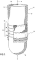
- a prosthetic liner 10 includes a liner body 12 defining an internal cavity 14 for receiving a residual limb.
- the liner body 12 preferably has an elongate, generally conical shape, and defines a longitudinal axis A which extends between proximal and distal portions 16, 20.
- the proximal and distal portions 16, 20 are spaced apart by a middle portion 18.
- the liner body 12 may be formed from at least one material segment that is at least radially elastically extensible from a relaxed non-extended condition.
- a seal component 22 is securable to an outer surface of the liner body 12 among an at least one seal band 26 formed along the outer surface of the liner body. 12
- the at least one seal band 26 defines at least three seal bands 28, 30 and 32 located about a circumference of the middle portion 18.
- the seal bands 28, 30, 32 may be formed from a frictional material to maintain the seal component 22 on the prosthetic liner 10.
- An example of a frictional material is silicone, however other suitable materials may be used.
- the seal component 22 frictionally fits against at least one of the seal bands 28, 30, 32 along a length of the liner body 12 and can be installed among any one of the seal bands 28, 30, 32.
- the seal component 22 can likewise be removed from the liner body 12 and readjusted as considered necessary at a new location.
- the seal component 22 can be arranged to frictionally fit against a liner body 12 without any of the seal bands 28, 30, 32.
- the seal component 22 can be arranged to frictionally fit against a prosthetic liner comprising a textile-free prosthetic liner then for example the length of a liner sealing portion described below can be much shorter.
- the seal component 22 is considered detachable in that it can be removed from the liner body 12, and adjustable to be repositioned on the liner body 12 without any adhesive or permanency. According to a desired height of the seal component 22 along the axis A of the liner body 12, the seal component 22 can be installed among any one or more of the seal bands 28, 30, 32.
- the seal component 22 includes a body having an outer surface defining a socket sealing portion arrange to engage with and form an airtight seal with an interior surface of the socket.
- An inner surface of the body defines a liner sealing portion extending in a proximal direction from an end of the socket sealing portion on the outer surface of the body.
- the liner sealing portion is arranged to frictionally engage and seal with the outer surface of the liner body 12, including at least one of the seal bands 28, 30, 32 to secure the seal component 22 on the liner body 12.
- the liner sealing portion and the socket sealing portion are defined on different parts of the seal component 22.
- the liner sealing portion can extend between the end of the socket sealing portion and a proximal end of the body. It has been found that one source of undesirable migration of movable seal components between the socket and the prosthetic liner is that a sealing length of the liner sealing portion along the inside of the seal component in relation to a sealing length of the socket sealing portion along the outside of the seal component is typically too short, and thus the amount of traction between the socket and seal component tends to overcome the amount of traction between the seal component and the prosthetic liner, causing the seal component to migrate or undesirably move between the socket and the prosthetic liner.
- traction generally refers to the amount of force a body can apply to a surface or another body before it slips.
- the sealing length and/or position of the liner sealing portion is selectively configured in relation to the socket sealing portion to vary the traction at the inner and outer surfaces of the seal component 22.
- the liner sealing portion can comprise a sealing length of between about 25 mm and about 3 5 mm.
- Such a sealing length can provide an amount of traction along the inner surface of the seal component 22 that is neither too low nor too concentrated, accomplishing a secure suspension of the prosthetic liner 10 and residual limb within the socket that avoids unwanted migration of the seal component 22 without making the seal component 22 uncomfortable to use or difficult to don/doff.
- Such a sealing length along the liner sealing portion also can facilitate donning and doffing of the seal component 22 and limit unwanted bunching of the seal component 22. If the amount of traction at the outer surface of the seal component 22 substantially exceeds the amount of traction at the inner surface, movement of the seal component 22 with the socket may generate shear forces that cause the liner sealing portion to slip relative to the prosthetic liner 10, which, in turn, can cause unwanted bunching or movement of the seal component 22 on a liner body 12.
- seal component 22 thus allows for more reliable suspension of a residual limb within a socket and reduces the likelihood of the seal component 22 undesirably migrating between the prosthetic liner 10 and the socket during use.
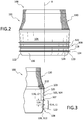
- Figs. 2 and 3 show an adjustable seal system 100 comprising seal component 101 according to an embodiment of the present disclosure.
- the seal component 101 defines a body 102 having open upper and lower ends defining an opening therethrough and an inner surface 103 extending about an axis B and arranged to abut a surface of a liner body (e.g., the liner body 12). While the body 102 is shown and described including an open lower end, it will be appreciated that the open lower end can be omitted from any seal component of the present disclosure.
- the body 102 can include an open upper end and a closed lower end.
- the body 102 can include an upper section 104 and a lower section 106.
- the upper portion 104 is arranged to be generally concentric with a liner body and can have a substantially uniform diameter along its length or height.
- the lower portion 106 defines a curvature 112 toward its lower end that decreases an inner diameter of the seal component 101. This allows the lower end 106 to compress against a liner body when the seal component 101 is donned thereon, advantageously helping to minimize unwanted relative movement between the seal component 101 and the liner body.
- a plurality of seal elements 108 are located along an outer surface 105 of the seal component 101.
- the seal elements 108 protrude radially outward from a body profile 122 and are arranged for engagement with an interior surface of a socket.
- the seal elements 108 collectively define a socket sealing portion 114 arranged to form a seal or attachment between the seal component 101 and the interior surface of the socket, providing resistance to axial and/or rotational movement between the seal component 101 and the socket during use.
- the socket sealing portion 114 defines a sealing length L1 that at least in part defines the amount of traction between the outer surface 105 of the seal component 101 and the interior surface of the socket. For instance, a decrease in the sealing length L1 can decrease the traction between the seal component 101 and the interior surface of the socket, and an increase in the sealing length L1 can increase the traction between the seal component 101 and the interior surface of the socket.
- the inner surface 103 of the seal component 101 defines a liner sealing portion 116 extending in a proximal direction from an end 107 of the socket sealing portion 114 on the body 102.
- the liner sealing portion 116 is configured to provide a sealing interface between the inner surface 103 of the body 102 and the outer surface of the prosthetic liner.
- the liner sealing portion 116 can define a sealing length L2 generally extending between a proximal edge on the body 102 and the end 107 of the socket sealing portion 114.
- the proximal edge on the body 102 can comprise an upper end 110 of the body 102.
- the sealing length L2 at least in part defines the amount of traction between the outer surface of the prosthetic liner and the inner surface 103 of the seal component 101.
- a decrease in the sealing length L2 can decrease the amount of traction between the seal component 101 and the outer surface of the prosthetic liner, and an increase in the sealing length L2 can increase the amount of traction between the seal component 101 and the outer surface of the prosthetic liner.
- the sealing length L2 of the liner sealing portion 116 can be arranged to span a distance between at least two seal bands on the prosthetic liner and to engage therewith. As such, the sealing length L2 of the liner sealing portion 116 can be selectively configured in relation to a distance between at least two seal bands on the prosthetic liner to vary the traction at the inner surface 103 of the seal component 101.
- the sealing length L2 of the liner sealing portion 116 can be between about 1 and about 1.4 times (e.g., about 1.2 times) greater than a distance between at least two seal bands on the prosthetic liner, ensuring sufficient traction and sealing between the seal component 101 and the prosthetic liner.
- the sealing length of the liner sealing portion 116 can be between about 28 mm and about 32 mm (e.g., about 30 mm) and the distance between at least two seal bands on the prosthetic liner that the liner sealing portion 116 is arranged to span and engage with can be about 25 mm.
- the sealing length of the liner sealing portion 116 can be between about 24 mm and about 26 mm (e.g., about 25 mm) and the distance between at least two seal bands on the prosthetic liner that the liner sealing portion 116 is arranged to span and engage with can be about 20 mm. In other embodiments, the sealing length L2 of the liner sealing portion 116 can be arranged to span across at least one seal band and to engage therewith.
- the liner sealing portion 116 and the socket sealing portion 114 are formed on different parts of the seal component 101.
- the liner sealing portion 116 and the socket sealing portion 114 can be offset along the axis B of the seal component 101. It has been found that the traction along the socket sealing portion 114 between the seal elements 108 and the interior surface of the socket can cause a region of the inner surface 103 opposite the socket sealing portion 114 to tend to move away from the outer surface of the prosthetic liner, reducing the amount of traction and increasing the among of air leaking or escaping between the inner surface 103 of the seal component 101 and the prosthetic liner, and accordingly increasing the likelihood of slippage between the seal component 101 and the prosthetic liner.
- the operation of the socket sealing portion 114 is less likely to directly influence the operation of the liner sealing portion 116. This advantageously allows for sufficient traction to be generated along the socket sealing portion 114, without directly affecting the strength or operation of the traction generated along the liner sealing portion 116.
- the sealing length L2 and/or position of the liner sealing portion 116 is selectively configured in relation to the socket sealing portion 114 to vary the traction at the inner and outer surfaces 103, 105 of the seal component 101.
- the sealing length L2 of the liner sealing portion 116 can be selected based on the sealing length L1 of the socket sealing portion 114.
- the sealing length L2 of the liner sealing portion 116 can be between about 1.2 and about 1.3 times greater than the sealing length L1 of the socket sealing portion 114.
- the sealing length L2 of the liner sealing portion 116 can be between about 0.9 and 1.6, between about 1 and 1.5, or between about 1.1 and 1.4 times greater than the sealing length L1 of the socket sealing portion 114.
- the sealing length L1 of the socket sealing portion 114 can be between about 22 mm and 27 mm (e.g., about 25 mm) and the sealing length L2 of the liner sealing portion 116 can be between about 28 mm and 32 mm (e.g., about 30 mm). It will be appreciated that in other embodiments the relationship between the sealing lengths of the liner sealing portion 116 and the socket sealing portion 114 can be greater or lower.
- the sealing length L2 of the liner sealing portion 116 can be shorter if there is less distance between adjacent seal bands on a prosthetic liner.
- a sealing length L2 of the liner sealing portion 116 for use with a prosthetic liner including seal bands spaced apart by about 20 mm can be shorter than a sealing length L2 of the linear sealing portion 116 for use with a prosthetic liner including seal bands spaced about by about 25 mm.
- the sealing length L2 of the liner sealing portion 116 is preferably between about 25 mm and about 35 mm (e.g., about 30 mm). This provides an amount of traction along the inner surface 103 of the seal component 101 that can substantially maintain the position of the seal component 101 on a prosthetic liner when a typical amount of traction for suspending the socket is present along the socket sealing portion 114, reducing the likelihood of undesirable migration of the seal component 101 and improving reliability of the attachment formed by the seal component 101 between the prosthetic liner and the socket.
- This sealing length L2 is also not too concentrated such as would form pressure points on a residual limb, thereby improving user comfort. It is also not too great or extensive, thereby reducing the likelihood of the traction along the liner sealing portion 116 overcoming the amount of traction along the socket sealing portion 114, and improving the reliability of the attachment formed by the seal component 101 between the prosthetic liner and the socket. Additionally, a sealing length L2 of between about 25 mm and about 30 mm along the liner sealing portion 116 is not too great to make manual movement of the seal component 101 on the prosthetic liner by a user too difficult, facilitating donning and doffing of the seal component 101. In other embodiments, the sealing length L2 can be between about 26 mm and 34 mm, about 27 mm and 33 mm, or about 29 mm and 31 mm. It will be appreciated that the sealing length L2 can be greater or smaller in other embodiments.
- the amount of traction generated along the socket sealing portion 114 can be at least in part defined by the configuration of the seal elements 108.
- the socket sealing portion 114 can define a greater traction with a shorter sealing length L1 based on the form of the seal elements 108.
- the sealing length L2 of the liner sealing portion 116 can thus be configured in relation to the configuration of the seal elements 108. This has the effect of reducing the likelihood of problems that can result when the traction generated by the structure of the seal elements 108 overrides the traction generated along the liner sealing portion 116, as previously discussed; for example, the unwanted bunching or migration of the seal component 101 along the prosthetic liner can be avoided.
- the seal elements 108 can have a resilient configuration extending in a distal direction from the end 107 and protruding radially from a body profile 122 of the seal component 101.
- Each of the seal elements 108 includes proximal and distal sections 118, 120 extending from the body profile 122 to a peak 124 defined as the outermost extending portion of the seal element 108.
- the proximal and distal sections 118, 120 can be generally parallel to one another and the peak 124 can be rounded.
- the seal elements 108 are spaced apart from one another a gap 126 and are arranged to resiliently deflect toward the body profile 122 when the seal component 101 is donned on a liner body and placed within a socket.
- the seal elements 108 could be formed of the same material as the body 102 and created integrally in one piece with the body 102 during molding or forming of the body 102, or alternatively, could be formed of a softer or stiffer material or a material more suitable for a seal than the material forming the body, and then secured to the body 102.
- the seal elements 108 are shown comprising three seal elements 108 but can include any suitable number of seal elements.
- At least one grip ring 128 is formed on the body profile 122 in the socket sealing portion 114.
- the grip rings 128 can extend circumferentially about the body 102 and can comprise a plurality of grip rings 128 located between adjacent ones of the seal elements 108.
- the grip rings 128 are configured to grab the interior surface of the socket in the gaps 126 located between the seal elements 108. This advantageously can increase the amount of traction in the socket sealing portion 114 and reduce the likelihood of slippage in the gaps 126 between the seal elements 108.
- the placement of the grip rings 128 in the gaps 126 between the seal elements 108 can help reduce interference from the grip rings 128 with the sealing function of the sealing elements 108.
- the grip rings 128 can be formed of a frictional material and can have a rounded cross-sectional shape. In other embodiments, the grip rings 128 can have a rectangular, trapezoidal, wave, or other cross-sectional shape.
- the grip rings 128 can be formed of a same or different material as the seal component 101.
- the grip rings 128 have a radially short configuration in relation to the seal elements 108 such that the seal elements 108 significantly extend beyond the grip rings 128 in a radial direction relative to the axis B. More particularly, the seal elements 108 can have a height defined between the body profile 122 and the peak 124, and the grip rings 128 can have a height defined between the body profile 122 and an outer radial limit of the grip ring 128. In an embodiment, the height of at least one of the seal elements 108 can be more than about 4 or about 5 times the height of at least one of the grip rings 128.
- the grip rings 128 can also be configured to maintain the position of the peaks 124 of the seal elements 108 away from the body profile 122 when the seal elements 108 deflect toward the body profile 122.
- the grip rings 128 can be positioned in the gaps 126 such that as the peak 124 of a seal element 108 resiliently deflects toward the body profile 122, the proximal section 118 or distal section 120 of the seal element 108 engages with at least one of the grip rings 128 before reaching the body profile 122, maintaining the peak 124 a distance radially from the body profile 122.
- This advantageously can decrease the likelihood of the seal elements 108 sticking to or flattening out against the body profile 122 when the seal component 101 is inserted into a socket, which can undesirably restrict movement of the seal element 108 relative to the body 102 and can compromise the seal formed by the seal element 108 against the interior surface of the socket.
- the grip rings 128 can thus help increase the amount of traction along the socket sealing portion 114 and/or improve the reliability of the seal formed by the seal element 108 against the interior surface of the socket.
- the amount of traction at the socket sealing portion 114 and/or the liner sealing portion 116 can be controlled by varying materials, surface treatments, and/or texturing of the body 102 and/or seal elements 108.
- the socket sealing portion 114 can be treated with a low friction coating.
- the socket sealing portion 114 can be treated with Easy Glide®.
- a textile sleeve 130 can be secured to the upper portion 104 of the seal component 101 and arranged to radially compress against the outer surface of the liner body.
- the textile sleeve 130 is preferably an anatomically conforming fabric.
- the textile provides an interface for griping, and thereby minimizing fine hand movement needed to don and adjust the seal component 101 over the prosthetic liner.
- the sleeve 130 is preferably more flexible and elastic than the seal component 101 such that the sleeve 130 retracts to an original size upon release of tension of the sleeve 130, further minimizing the risk of unwanted migration while not impeding donning/doffing of the seal component 101.
- the sleeve 130 has a diameter less than a diameter of the liner body at the distal portion of the sleeve 130 such that the sleeve 130 stretches over and is tensioned when selectively placed over the outer surface of the liner body.
- the sleeve 130 can include a main portion having a first elasticity, and a top band located at an upper end of the main portion and having a second elasticity. It will be appreciated that any of the seal components of the present disclosure may optionally include a textile sleeve 130 as described herein.
- Fig. 4 shows an adjustable seal system 200 according to another embodiment comprising a seal component 201 with a plurality of seal elements 208 and a liner sealing portion 216.
- the seal component 201 defines a body 202 having open upper and lower ends defining an opening therethrough and an inner surface 203 arranged to abut an outer surface of a liner body.
- the profile of the seal elements 208 includes curvilinear proximal and distal sections 218, 220 extending from a body profile 222 toward a rounded peak 224.
- the seal elements 208 form a socket sealing portion 214 for sealing the sealing component 201 to a socket and the inner surface 203 defines the liner sealing portion 216 extending in a proximal direction from an end 207, which may be a proximal end, of the socket sealing portion 214 on the body 202.
- the liner sealing portion 216 is configured to provide a sealing interface between the seal component 201 and the liner body beyond the seal elements 208.
- the socket sealing portion 214 defines a sealing length L3 that at least in part defines the amount of traction between an outer surface 205 of the seal component 201 and the interior surface of the socket.
- the liner sealing portion 216 defines a sealing length L4 that at least in part defines the amount of traction between the outer surface of the prosthetic liner and the inner surface 203 of the seal component 201.
- the sealing length L4 can be defined between a proximal edge on the body 202 and the end 207 of the socket sealing portion 216.
- the proximal edge of the body 202 can define an upper end 210 of the body 202.
- the sealing length L4 and/or position of the liner sealing portion 216 can be selectively configured in relation to the socket sealing portion 214 to vary the traction at the inner and outer surfaces 203, 205 of the seal component 201.
- the liner sealing portion 216 and the socket sealing portion 214 can be axially offset from one another on the body 202, reducing the likelihood of undesirable interface between the socket sealing portion 214 and the liner sealing portion 216.
- the sealing length L4 of the liner sealing portion 216 can be between 25 mm and about 35 mm (e.g., about 30 mm).
- this configuration of the liner sealing portion 216 can provide an amount of traction along the inner surface 203 of the seal component 201 that is sufficient to substantially maintain the position of the seal component 201 on a prosthetic liner when a typical amount of traction for suspending the socket is generated along the socket sealing portion 214, without being so concentrated or extensive that the seal component 201 creates discomfort from, e.g., pressure points, or difficulty in donning/doffing the seal component 201.
- Fig. 5 shows an adjustable seal system 300 according to yet another embodiment comprising a seal component 301 with a plurality of seal elements 308 and a liner sealing portion 316.
- the seal component 301 defines a body 302 having open upper and lower ends defining an opening therethrough and an inner surface 303 arranged to abut a surface of a liner body.
- the seal elements 308 form a socket sealing portion 314 for sealing the sealing component 301 to a socket and the inner surface 303 defines the liner sealing portion 316 extending a proximal direction from an end 307 of the socket sealing portion 314 on the body 302.
- the liner sealing portion 316 is configured to provide a sealing interface between the seal component 301 and the liner body beyond the seal elements 308.
- the socket sealing portion 314 defines a sealing length L5 that at least in part defines the amount of traction between an outer surface 305 of the seal component 301 and the interior surface of the socket.
- the liner sealing portion 316 defines a sealing length L6 that at least in part defines the amount of traction between the outer surface of the prosthetic liner and the inner surface 303 of the seal component 301.
- the liner sealing portion 316 generally extends between the end 307 of the socket sealing portion 314 and a proximal edge on the body 302. The proximal edge on the body 302 can define an upper end 310 of the body 302.
- the sealing length L6 and/or position of the liner sealing portion 316 can be selectively configured in relation to the socket sealing portion 314 to vary the traction at the inner and outer surfaces 30, 305 of the seal component 301.
- the liner sealing portion 316 and the socket sealing portion 314 may be axially offset from one another on the body 302, reducing the likelihood of undesirable interference between the socket sealing portion 314 and the liner sealing portion 316.
- the sealing length L6 of a liner sealing portion 316 be between about 25 mm and about 35 mm to create and optimize a more reliable connection between a residual limb and the socket.
- the profile of the seal elements 308 may be tapered from a distal end toward a proximal end to facilitate insertion of the seal component 301 into the socket and tends to resist outward movement of the seal component 301 from the socket.
- the tapered form of the seal elements 308 can provide an increased sealing force between the seal component 301 and the socket when the seal component 301 is moved in a direction tending to withdraw it from the socket, or in other words the seal elements 308 seal more effectively when subjected to a pressure differential where a lower pressure exists towards the distal side of the seal element as compared to the proximal side thereof.
- Fig. 6 shows an adjustable seal system 400 according to another embodiment comprising a seal component 401.
- the seal component 401 includes a single seal element 408 and a grip ring 428 positioned proximal of the seal element 408.
- the seal element 408 and the grip ring 428 define a socket sealing portion 414 arranged to form a seal or attachment between the seal component 401 and the interior surface of the socket.
- the inner surface 403 of the seal component 401 defines a liner sealing portion 416 extending a proximal direction from an end 407 of the socket sealing portion 414 on the body 402.
- the liner sealing portion 416 is configured to provide a sealing interface between the inner surface 403 of the body 402 and the outer surface of the prosthetic liner beyond or proximal to the socket sealing portion 414.
- the socket sealing portion 414 defines a sealing length L7 that at least in part defines the amount of traction between an outer surface 405 of the seal component 401 and the interior surface of the socket.
- the liner sealing portion 416 defines a sealing length L8 that at least in part defines the amount of traction between the outer surface of the prosthetic liner and the inner surface 403 of the seal component 401.
- the liner sealing portion 416 generally extends between the end 407 of the socket sealing portion 414 and a proximal edge on the body 402.
- the sealing length L8 and/or the position of the liner sealing portion 416 can be selectively configured in relation to the socket sealing portion 414 to vary the traction at the inner and outer surfaces 403, 405 of the seal component 401.
- the sealing length L8 is substantially greater than the sealing length L7 but also not too long to make manual movement of the seal component 401 on the prosthetic liner by a user too difficult, facilitating donning and doffing of the seal component 401 for a user.
- the profile of the seal element 408 is shown defining an elongate rectangular shape but can define any suitable shape.
- the grip ring 428 can be arranged to provide additional traction between the seal component 401 and a prosthetic socket.
- the grip ring 428 can also be arranged to reduce the likelihood of the seal element 408 undesirably sticking to the body profile 422 during use, such as when the prosthetic liner is inserted into the socket.
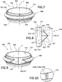
- Figs. 7-9 show an adjustable seal system 500 according to another embodiment comprising a seal component 501.
- the seal component 501 defines a body 502 forming an inner surface 503 arranged to engage with a liner body.
- the body 502 includes an upper section 504 and a lower section 506.
- a seal element 508 is attached to the outer surface 505 of the seal component 501 and arranged for engagement with an interior surface of a socket.
- the seal element 508 defines a socket sealing portion 514 arranged to create a seal or attachment between the seal component 501 and the interior surface of the socket that provides resistance to axial and/or rotational movement between the seal component 501 and the socket during use.
- the inner surface 503 of the body 502 defines a liner sealing portion 516 extending in a proximal direction from an end 507 of the socket sealing portion 514 on the body 502 comprising a connection point 513 between the body 502 and the seal element 508.
- the liner sealing portion 516 is configured to provide a sealing interface between the inner surface 503 of the body 502 and the outer surface of the prosthetic liner.
- the socket sealing portion 514 defines a sealing length L9 that at least in part defines the amount of traction between the seal component 501 and the interior surface of the socket.
- the liner sealing portion 516 defines a sealing length L10 that at least in part defines the amount of traction between the outer surface of the prosthetic liner and the inner surface 503 of the seal component 501.
- the sealing length L10 can be defined between a proximal edge on the body 502 and the connection point 513.
- the proximal edge can define an upper end 510 of the body 502.
- the liner sealing portion 516 and the socket sealing portion 514 are defined on different parts of the seal component 501.
- the liner sealing portion 516 is defined along the body 502 proximal to the connection point 513
- socket sealing portion 514 is defined on a member other than the body 502.
- the seal element 508 can comprise a member cantilevered from the connection point 513 on the body and separated from the body 502 by a variable space 530. The seal element 508 can thus freely flex relative to the body 502, and the liner sealing portion 516 and the socket sealing portion 514 are separated by the variable space 530.
- the sealing length L10 and/or position of the liner sealing portion 516 is selectively configured in relation to the socket sealing portion 514 to vary the traction at the inner and outer surfaces 503, 505 of the seal component 501.
- the sealing length L10 of the liner sealing portion 516 can be between 25 mm and about 35 mm (e.g., about 30 mm). This provides an amount of traction along the inner surface 503 of the seal component 501 that can substantially maintain the position of the seal component 501 on a prosthetic liner when a typical amount of traction for suspending the socket is present along the socket sealing portion 514, reducing the likelihood of undesirable movement or migration of the seal component 501 between the prosthetic liner and the socket, and improving reliability of the seal component 501.
- the sealing length of the liner sealing portion 516 is also not too short to generate pressure points on a residual limb, improving comfort of the seal component 501.
- the sealing length L10 of the liner sealing portion 516 can be between about 30 mm and 45 mm, between about 33 mm and 42 mm, or between about 35 mm and about 40 mm (e.g., about 39 mm).
- the sealing length L9 can be between about 20 mm and about 34 mm, about 22 mm and about 30 mm, or about 25 mm and about 28 mm (e.g., about 27 mm). It will be appreciated that the sealing lengths L9, L10 can be greater or smaller.
- the seal element 508 can be configured to vary the amount of traction along the socket sealing portion 514.
- the seal element 508 has a radially outermost portion, peak, or seal lip 524 arranged generally concentric with the upper portion 504.
- a lower segment 520 extends outwardly and in some embodiments conically from the connection point 513 to the seal lip 524.
- An upper segment 518 extends inwardly from the seal lip 524 toward the upper portion 504 of the body 502.
- a variable space 530 is defined between the body 502 and the upper segment 518 such that the seal element 508 is arranged to be compressed against a body profile 522 of the upper portion 504 when the seal component 501 is inserted in a socket.
- a flap 532 extends from the upper segment 518 and may be oriented generally parallel with the upper portion 504 and is spaced from the upper portion 504 by the variable space 530. It will be appreciated that socket sealing portion 514 can move relative to the liner sealing portion 516 to compensate for volume changes in the residual limb.
- the lower segment 520 defines at least one radial seal 532, 534 that, in combination with the seal lip 524, are arranged to maintain connection with an interior socket wall, thereby creating a seal between the seal component 501 and the socket.
- the body profile 522 defines one or more raised portions 540 radially positioned between the seal element 508 and the body 502.
- the one or more raised portions 540 are radially positioned between the seal element 508 and the upper portion 504 and are sized and configured to create channels for airflow between the upper portion 504 and the seal element 508 during use.
- the one or more raised portions 540 can be configured such that when the seal element 508 is compressed against the body 502 during donning or loading of the prosthetic liner within the socket, closing the variable space 530 toward the body profile 522, the seal element 508 engages with the one or more raised portions 540 before reaching the body profile 522, maintaining at least a portion of the seal element 508 a distance from the body profile 522.
- This distancing or spacing of the seal element 508 from the body profile 522 provided by the raised portions 540 can create channels between the body 502 and the seal element 508 for permitting airflow therebetween. This advantageously reduces the risk of the seal element 508 sticking or becoming stuck on the body profile 522, which can undesirably restrict movement of the seal element 508 relative to the body 502 and can compromise the seal formed by the seal element 508 against the interior surface of the socket, especially during use of the prosthesis, such as a leg or foot.
- the one or more raised portions 540 can thus help increase the amount of traction along the socket sealing portion 514 and/or improve the reliability of the seal formed by the seal element 508 against the interior surface of the socket. It will be appreciated that the channels formed by the raised portions 540 between the body profile 522 and the seal element 508 can be around and/or between the one or more raised portions 540.
- the one or more raised portions 540 can also provide rotation control between the seal element 508 and the body 502, reducing the likelihood of undesirable rotational issues.
- the one or more raised portions 540 can be configured to frictionally or mechanically grip the inner side of the seal element 508 to limit relative rotation between the seal element 508 and the body 502.
- the one or more raised portions 540 can define a variety of shapes such as bubble, dome, arcuate, semi-hemispherical, square, and other available shapes that may be molded on the body 502.
- the one or more raised portions 540 comprise a single protrusion on the body profile 522.
- the one or more raised portions 540 can comprise three linear protrusions 540A, 540B, and 540C as shown in Fig. 10 or any other suitable number or shape of raised portions.
- the one or more raised portions 540 can extend generally parallel to an axis C and/or obliquely relative to the axis C.
- the raised portions 540 can be comprise linear protrusions, curved protrusions, or both.
- the raised portions 540 can comprise coil protrusions or can extend in a cross-hatch or mesh pattern between the seal element 508 and the body 502.
- the raised portions 540 can extend along the entirety or part of the height of the body 502. For instance, the raised portions 540 can define a length generally corresponding to the flap 532. The raised portions 540 can extend downwardly from the top or proximal edge 510 of the body 502. It will be appreciated that any suitable seal component of the present disclosure may optionally include one or more raised portions 540 as described herein.
- Figs. 11 - 13 show yet another embodiment of an adjustable seal system 700 comprising a seal component 701 including a body 702 forming an inner surface 703 extending about an axis E and arranged to abut an outer surface of a liner body (e.g., liner body 12).
- the body 702 includes an upper section 704 and a lower section 706.
- the upper portion 704 is arranged to be generally concentric with the liner body and can have a substantially uniform diameter along its length of height.
- the lower section 706 defines a curvature 712 toward its lower end that decreases an inner diameter of the seal component 701. This curvature 712 allows the lower end to compress against the liner body when the seal component 701 is donned thereon, advantageously helping to minimize unwanted relative movement between the seal component 701 and the liner body.
- a plurality of seal elements 708 are formed along an outer surface 705 of the body 702.
- the seal elements 708 protrude radially outward from a body profile 722 and are arranged for engagement with a socket wall.
- the seal elements 708 are shown comprising five seal rings arranged for deflection and are axially spaced along the body profile 722 but can include any suitable number and/or structure of seal elements.
- the seal elements 708 form a socket sealing portion 714 for sealing the sealing component 701 to a socket and the inner surface 703 defines a liner sealing portion 716 that provides a sealing interface between the seal component 701 and the liner body.
- the liner sealing portion 716 and the socket sealing portion 714 are defined on different parts of the seal component 701.
- the socket sealing portion 714 is defined along the body profile 722 and the liner sealing portion 716 is defined on a separate interior wall 740 having an upper free end 745 and a lower end 747 connected to the lower section 706 on the inner surface 703 of the body 702.
- the liner sealing portion 716 is defined along the radial inner surface of the interior wall 740.
- the lower end 747 of the interior wall 740 can comprise an end 707 of the socket sealing portion 714.
- a variable space 742 is defined between the body 702 and the interior wall 740 such that the interior wall 740 is arranged to be compressed against the body 702 when the seal component 701 is donned on a prosthetic liner filling, reducing, or eliminating variable space 742.
- the interior wall 740 can thus freely move or pivot relative to the body 702, and the liner sealing portion 716 and the socket sealing portion 714 are separated by the variable space 742. This reduces the likelihood of undesirable interference between the socket sealing portion 714 and the liner sealing portion 716 and allows for traction to be generated along the socket sealing portion 714, without directly affecting the strength or operation of the traction generated along the liner sealing portion 716.
- the socket sealing portion 714 defines a sealing length L11 that at least in part defines the amount of traction between the seal component 701 and the interior surface of the socket.
- the liner sealing portion 716 defines a sealing length L12 that at least in part defines the amount of traction between the seal component 701 and the outer surface of the prosthetic liner.
- the sealing length L12 can be defined between an end 707 of the socket sealing portion 714 and a proximal edge on the body 702.
- the proximal edge on the body 702 can comprise the upper free end 745 of the interior wall 740.
- the sealing length L11 of the socket sealing portion 714 can be between about 60 mm and 80 mm, about 65 mm and 75 mm, or about 67 mm and 72 mm (e.g., 70 mm). This greater distance increases the area of the sealing interface between the seal component 701 and the socket, which, in turn, can more evenly distribute traction and is less likely to strangle, cut off circulation in, or otherwise create discomfort in a residual limb.
- the sealing length L12 and/or the position of the liner sealing portion 716 is selectively configured in relation to the socket sealing portion 714 to vary the traction at the inner and outer surfaces 703, 705 of the seal component 701.
- the sealing length of the liner sealing portion 716 can be between about 25 mm and about 35 mm.
- This configuration of the liner sealing portion 716 can provide an amount of traction along the inner surface 703 of the seal component 701 that is sufficient to substantially maintain the position of the seal component 701 on a prosthetic liner when a typical amount of traction for suspending the socket is generated along the socket sealing portion 714, reducing the likelihood of movement of the seal component 701 between the prosthetic liner and the socket, and improving reliability of the seal component 201.
- the seal component 701 can better compensate for volume changes in the residual limb to improve suspension of the adjustable seal component 701 over known adjustable seal components.
- an open-ended prosthetic sock 750 or fabric sleeve having a distal portion can be positioned within the variable space 742 between the interior wall 740 and the inner surface 702 as shown in Fig. 13 .
- This beneficially can provide cushioning and help locate the seal component 701 on the prosthetic liner to improve ease of use over known adjustable seal components.
- the compression of the interior wall 740 against the inner surface 702 can secure the prosthetic sock 750 within the variable space 742, helping to maintain the prosthetic sock 750 in a proper position during use.
- any seal component of the present disclosure may optionally include an interior wall and/or open-ended prosthetic sock as described herein.
- the socket sealing portion and/or liner sealing portion may be decided according to the needs of the user, and sensitive areas may be avoided.
- the adjustable seal components can be arranged to engage a liner body without any seal bands.
- the adjustable seal components can be arranged to engage with and secure on a liner comprising a textile free liner.
- the adjustable seal embodiments may enable improved durability by having better abrasion resistance due to the versatility in placement of the seal component and its separate yet non-permanent attachment to the liner.
- an adjustable seal is provided that can be removably mounted on a prosthetic liner and has a liner sealing portion configured to cooperate with a socket sealing portion to securely mount the adjustable seal on the prosthetic liner and to securely suspend the prosthetic liner and residual limb within the socket.
- the liner sealing portion is further advantageously configured to have a length sufficient to avoid unwanted migration of the adjustable seal without creation pressure points, discomfort, or difficulty in donning and doffing the adjustable seal component.
Landscapes
- Health & Medical Sciences (AREA)
- Cardiology (AREA)
- Oral & Maxillofacial Surgery (AREA)
- Transplantation (AREA)
- Engineering & Computer Science (AREA)
- Biomedical Technology (AREA)
- Heart & Thoracic Surgery (AREA)
- Vascular Medicine (AREA)
- Life Sciences & Earth Sciences (AREA)
- Animal Behavior & Ethology (AREA)
- General Health & Medical Sciences (AREA)
- Public Health (AREA)
- Veterinary Medicine (AREA)
- Prostheses (AREA)
Description
- This disclosure relates to suspension liners adapted to provide an interface between a residual limb and a prosthetic socket. The disclosure provides various embodiments of an adjustable seal system, seal components for use in the adjustable seal system, and methods for providing a sealing interface between a residual limb and a prosthetic socket.
- In certain existing prosthetic systems, including vacuum-type suspension systems, prosthetic liners may function to secure a residual limb within a prosthetic socket as the residual limb and the prosthetic liner are inserted into the socket in a close-fitting relationship, by isolating the distal end area of the hard socket from the atmosphere. Upon application of a pulling force on the prosthetic liner relative to the socket, suction is created in the isolated distal end of the socket, the section tending to retain the prosthetic liner within the socket. Appropriate devices are usually provided to enable expulsion of air between the distal end of the liner and the hard socket, and to isolate the distal end of the hard socket member from the atmosphere after the prosthetic liner with a residual limb has been fully inserted within the socket.
- In other applications, it may be desired to more positively secure the prosthetic liner within the socket by creating a hypobaric (vacuum) pressure within the distal end of the hard socket in a space defined between such distal end and the distal end of a prosthetic liner inserted into the socket with a residual limb contained within the prosthetic liner. The hypobaric pressure may be maintained at the distal end of the hard socket and the interior of the socket at its distal end will be isolated from atmosphere during normal retention of the sleeve liner within the socket. Opening the distal end of the socket to atmosphere releases the vacuum or hypobaric pressure within the socket to enable simple and easy withdrawal of a residual limb with a prosthetic liner thereon from the socket. A pump or other device may be utilized to evacuate the distal end of the socket between the distal end of a prosthetic liner and the distal end of a socket. A valve or other appropriate device typically is used to open and close the distal end of a socket to surrounding atmosphere.
- Various arrangements are known in certain existing prosthetic systems for providing a seal between the exterior of the prosthetic liner and the interior of the hard socket, the seal functioning to define a suspension chamber within the socket which is separated from atmospheric pressure, including a separate and movable seal 5positionable on the exterior of the prosthetic liner. These movable seals allow users to selectively position the movable seal on the exterior of the liner to a desired longitudinal position to avoid sensitive or compromised tissue and may also help users who experience volume changes during the day to maintain suspension.
- It is known for example from
US 2015/0142131 to provide an adjustable seal 10system including a seal component removably securing to an outer surface of a prosthetic liner. - Disadvantageously, however, these movable seals are also prone to undesirably migrate or move circumferentially or longitudinally between the prosthetic liner and the hard socket during use. This can create the potential for 15failure of the suspension of the residual limb. It also can result in relative movement between the liner and the hard socket, which, in turn, reduces user comfort and increases the likelihood of friction-related injuries such as friction blisters and skin irritation. Additionally, movable seals often overcompensate for unwanted movement by being so large and/or difficult to move that a user cannot effectively don and doff 20the moveable seal. Such overcompensated seals often create pressure points on the residual limb, reducing comfort.
- Accordingly, there is a need for an adjustable seal system with an improved seal component that allows for stable placement of the seal component on the liner, effective suspension of a residual limb within a socket, and flexibility in placement of 25the seal component.
- Embodiments of the present disclosure can include an adjustable seal component having a body having an outer surface defining a socket sealing portion arranged to engage with and form an airtight seal with an interior surface of a 30prosthetic socket. The inner surface of the body defines a liner sealing portion arranged to frictionally engage and seal with an outer surface of a prosthetic liner. The liner sealing portion defines a sealing length extending in a proximal direction from an end of the socket sealing portion and terminating at a proximal edge on the body. The sealing length of the liner sealing portion is between about 25 mm and 35 about 35 mm and is selected in relation to the socket sealing portion to vary tractions at the inner and outer surfaces of the seal component.
- This sealing length of the liner sealing portion can provide an amount of traction along the inner surface of the adjustable seal component that can substantially maintain the position of the adjustable seal component on the prosthetic liner when a typical amount of traction for suspending the residual limb within the prosthetic socket is present along the socket sealing portion, reducing the likelihood of undesirable migration of the adjustable seal component and thereby improving the reliability of the attachment formed by the adjustable seal component between the prosthetic liner and the prosthetic socket.
- This sealing length of the liner sealing portion is also not too concentrated such as would form pressure points on a residual limb, improving user comfort. It is also not too great or extensive in length, reducing the likelihood of the traction along the liner sealing portion overcoming the amount of traction along the socket sealing portion, improving the reliability of the attachment formed by the adjustable seal component between the prosthetic liner and the socket. Additionally, this sealing length is not too great or extensive such as would make manual movement of the seal component on the prosthetic liner by a user too difficult, facilitating donning and doffing of the adjustable seal component.
- According to a variation, the socket sealing portion is defined by a plurality of seal elements and a plurality of grip rings formed on the body and extending circumferentially about the outer surface of the body between the seal elements. The grip rings can be configured to enhance traction between the seal components and the interior of the socket.
- According to a variation, the socket sealing portion is defined by at least one seal element spaced by a clearance from the outer surface of the body. One or more raised portions are radially positioned between the at least one seal element and a body profile of the outer surface of the body.
- The one or more raised portions are configured such when the seal element is compressed against the body (closing the variable space toward the body profile) the seal element engages with the one or more raised portions before reaching the body profile, maintaining at least a portion of the seal element a distance from the body profile.
- This distancing or spacing of the seal element from the body profile provided by the raised portions can create channels between the body and the seal element for permitting airflow therebetween. This advantageously reduces the risk of the seal element sticking or becoming struck on the body profile, which can undesirably restrict movement of the seal element relative to the body and can compromise the seal formed by the seal element against the interior surface of the socket, especially during use. The one or more raised portions can thus help increase the amount of traction along the socket sealing portion and/or improve the reliability of the seal formed by the seal element against the interior surface of the socket.
- The numerous other advantages, features and functions of embodiments of an adjustable seal system will become clear and better understood in view of the following description, appended claims, and accompanying drawings. The following description is not intended to limit the scope of the adjustable seal system, but instead merely provides exemplary embodiments for ease of understanding.
-
Fig. 1 is a perspective view showing an embodiment of a prosthetic liner having a movable adjustable seal system according to the disclosure. -
Fig. 2 is an elevational view of a seal component according to an embodiment. -
Fig. 3 is a partial cross section of the seal component shown inFig. 2 in an elevational view. -
Fig. 4 is a partial cross section of a seal component in an elevational view according to another embodiment. -
Fig. 5 is a partial cross section of a seal component in an elevational view according to another embodiment. -
Fig. 6 is a partial cross section of a seal component in an elevational view according to another embodiment. -
Fig. 7 is a perspective view of a seal component according to another embodiment. -
Fig. 8 is a partial cross section of the seal component shown inFig. 7 in an elevational view. -
Fig. 9 is a partial cutaway of the seal component shown inFig. 7 in a perspective view. -
Fig. 10 is a detailed perspective view of the seal component according to another embodiment. -
Fig. 11 is a perspective view of a seal component according to another embodiment. -
Fig. 12 is a cross section of the seal component shown inFig. 11 in a perspective view. -
Fig. 13 is another cross section of the seal component shownFig. 11 in a perspective view including a prosthetic sock. - The drawing figures are not necessarily drawn to scale, but instead are drawn to provide a better understanding of the components, and are not intended to be limiting in scope, but to provide exemplary illustrations. The figures illustrate exemplary configurations of an adjustable seal system, and in no way limit the structures or configurations of an adjustable seal system and components according to the disclosure.
- A better understanding of different embodiments of the invention may be had from the following description read in conjunction with the accompanying drawings in which like reference characters refer to like elements.
- In each of the embodiments discussed herein, the suspension or prosthetic liner is intended for use between a residual limb and a prosthesis, such as a hard socket, and to be air-tight when donned over a residual limb. The inner surface of the prosthetic liner may be formed of a layer of silicone elastomer, thereby serving as a skin surface.
- Silicone is advantageous and exemplary in that it allows for different levels and softness and strength to be incorporated into the liners of the present application. Moreover, silicone permits the addition of selected supplements, such as petroleum jelly and/or Aloe vera, which improve skin care and comfort. The suspension liner, however, can be constructed from a variety of other materials other than from silicone, and the embodiments herein are not limited to suspension liners formed from silicone.
- An elasticity-controlling matrix material may be provided on the exterior of the prosthetic liner, the elasticity-controlling matrix material preferably being relatively compliant in a radial direction and substantially rigid or inelastic in an axial direction. The matrix material may extend over the distal or external side of the prosthetic liner and is advantageous in that it prevents movement of the prosthetic liner when a prosthesis, such as a socket, is worn thereover.
- A prosthetic liner in accordance with this disclosure may be fabricated in enough sizes to accommodate various sizes of residual limbs. In use, a liner of the type described herein is rolled up from the proximal to the distal end, placed over the distal end of the residual stump and rolled back up or "donned" over the stump like a stocking.
- In use, a prosthetic liner carrying a seal component is worn on a residual limb and stepped into a prosthetic socket. As the residual limb is placed into the socket, the seal component forms an airtight seal with an interior surface of the socket and urges air out of the distal end of the socket through a distally positioned expulsion valve. When it is desired to release the connection between the prosthetic liner and the socket, the valve is released to allow a return to atmospheric or ambient pressure, and the residual limb and prosthetic liner can be removed from the socket.
- When sealing against a socket, it should be kept in mind that the vacuum is formed between the seal component and the distal end of the socket; generally, no vacuum is created proximal of the seal between the prosthetic liner and the socket. Depending on configurations of the seal component, the seal component may not completely press against the socket wall, but rather only portions of the seal component press against the socket wall. For example, seal rings of the seal component may press against the socket wall, but portions, such as regions coaxial with and between the seal rings may not touch the socket wall.
- Pressure is inversely proportional to the suspension force needed or provided to ensure stability and rotational control. The seal component preferably forms a hypobaric sealing membrane that conforms to the shape of the internal socket wall, providing an airtight seal between the prosthetic liner and the socket. Thus, the lower the pressure (or in other words, the greater the vacuum) between the seal component and the socket wall, the greater the suspension that is generated. It is often desirable that even pressure exists around the seal component in the connection between the socket and prosthetic liner. There is preferably firm suspension among the prosthetic liner, socket, and residual limb.
- In observing
Fig. 1 , aprosthetic liner 10 includes aliner body 12 defining aninternal cavity 14 for receiving a residual limb. Theliner body 12 preferably has an elongate, generally conical shape, and defines a longitudinal axis A which extends between proximal anddistal portions distal portions middle portion 18. Theliner body 12 may be formed from at least one material segment that is at least radially elastically extensible from a relaxed non-extended condition. - A
seal component 22 is securable to an outer surface of theliner body 12 among an at least oneseal band 26 formed along the outer surface of the liner body. 12 In this embodiment, the at least oneseal band 26 defines at least threeseal bands middle portion 18. Theseal bands seal component 22 on theprosthetic liner 10. An example of a frictional material is silicone, however other suitable materials may be used. Theseal component 22 frictionally fits against at least one of theseal bands liner body 12 and can be installed among any one of theseal bands seal component 22 can likewise be removed from theliner body 12 and readjusted as considered necessary at a new location. In other embodiments, theseal component 22 can be arranged to frictionally fit against aliner body 12 without any of theseal bands seal component 22 can be arranged to frictionally fit against a prosthetic liner comprising a textile-free prosthetic liner then for example the length of a liner sealing portion described below can be much shorter. - The
seal component 22 is considered detachable in that it can be removed from theliner body 12, and adjustable to be repositioned on theliner body 12 without any adhesive or permanency. According to a desired height of theseal component 22 along the axis A of theliner body 12, theseal component 22 can be installed among any one or more of theseal bands - According to the present disclosure, the
seal component 22 includes a body having an outer surface defining a socket sealing portion arrange to engage with and form an airtight seal with an interior surface of the socket. An inner surface of the body defines a liner sealing portion extending in a proximal direction from an end of the socket sealing portion on the outer surface of the body. The liner sealing portion is arranged to frictionally engage and seal with the outer surface of theliner body 12, including at least one of theseal bands seal component 22 on theliner body 12. - The liner sealing portion and the socket sealing portion are defined on different parts of the
seal component 22. For instance, the liner sealing portion can extend between the end of the socket sealing portion and a proximal end of the body. It has been found that one source of undesirable migration of movable seal components between the socket and the prosthetic liner is that a sealing length of the liner sealing portion along the inside of the seal component in relation to a sealing length of the socket sealing portion along the outside of the seal component is typically too short, and thus the amount of traction between the socket and seal component tends to overcome the amount of traction between the seal component and the prosthetic liner, causing the seal component to migrate or undesirably move between the socket and the prosthetic liner. As used herein, traction generally refers to the amount of force a body can apply to a surface or another body before it slips. - In accordance with the present disclosure, then, the sealing length and/or position of the liner sealing portion is selectively configured in relation to the socket sealing portion to vary the traction at the inner and outer surfaces of the
seal component 22. For instance, the liner sealing portion can comprise a sealing length of between about 25 mm and about 3 5 mm. Such a sealing length can provide an amount of traction along the inner surface of theseal component 22 that is neither too low nor too concentrated, accomplishing a secure suspension of theprosthetic liner 10 and residual limb within the socket that avoids unwanted migration of theseal component 22 without making theseal component 22 uncomfortable to use or difficult to don/doff. - This has the effect of reducing the likelihood of pressure points and/or unwanted movement between the
liner body 12 and theseal component 22, making prosthetic suspension more comfortable and reliable. Such a sealing length along the liner sealing portion also can facilitate donning and doffing of theseal component 22 and limit unwanted bunching of theseal component 22. If the amount of traction at the outer surface of theseal component 22 substantially exceeds the amount of traction at the inner surface, movement of theseal component 22 with the socket may generate shear forces that cause the liner sealing portion to slip relative to theprosthetic liner 10, which, in turn, can cause unwanted bunching or movement of theseal component 22 on aliner body 12. Conversely, if the amount of traction between theseal component 22 and theprosthetic liner 10 is too great, it can make donning and doffing of theseal component 22 too strenuous and inconvenient. Theseal component 22 thus allows for more reliable suspension of a residual limb within a socket and reduces the likelihood of theseal component 22 undesirably migrating between theprosthetic liner 10 and the socket during use. -
Figs. 2 and 3 show anadjustable seal system 100 comprisingseal component 101 according to an embodiment of the present disclosure. Theseal component 101 defines a body 102 having open upper and lower ends defining an opening therethrough and aninner surface 103 extending about an axis B and arranged to abut a surface of a liner body (e.g., the liner body 12). While the body 102 is shown and described including an open lower end, it will be appreciated that the open lower end can be omitted from any seal component of the present disclosure. For instance, the body 102 can include an open upper end and a closed lower end. - The body 102 can include an
upper section 104 and alower section 106. Theupper portion 104 is arranged to be generally concentric with a liner body and can have a substantially uniform diameter along its length or height. Thelower portion 106 defines acurvature 112 toward its lower end that decreases an inner diameter of theseal component 101. This allows thelower end 106 to compress against a liner body when theseal component 101 is donned thereon, advantageously helping to minimize unwanted relative movement between theseal component 101 and the liner body. - A plurality of
seal elements 108 are located along anouter surface 105 of theseal component 101. Theseal elements 108 protrude radially outward from abody profile 122 and are arranged for engagement with an interior surface of a socket. - As seen in the illustrated embodiment, the
seal elements 108 collectively define asocket sealing portion 114 arranged to form a seal or attachment between theseal component 101 and the interior surface of the socket, providing resistance to axial and/or rotational movement between theseal component 101 and the socket during use. Thesocket sealing portion 114 defines a sealing length L1 that at least in part defines the amount of traction between theouter surface 105 of theseal component 101 and the interior surface of the socket. For instance, a decrease in the sealing length L1 can decrease the traction between theseal component 101 and the interior surface of the socket, and an increase in the sealing length L1 can increase the traction between theseal component 101 and the interior surface of the socket. - The
inner surface 103 of theseal component 101 defines aliner sealing portion 116 extending in a proximal direction from anend 107 of thesocket sealing portion 114 on the body 102. Theliner sealing portion 116 is configured to provide a sealing interface between theinner surface 103 of the body 102 and the outer surface of the prosthetic liner. - The
liner sealing portion 116 can define a sealing length L2 generally extending between a proximal edge on the body 102 and theend 107 of thesocket sealing portion 114. The proximal edge on the body 102 can comprise anupper end 110 of the body 102. The sealing length L2 at least in part defines the amount of traction between the outer surface of the prosthetic liner and theinner surface 103 of theseal component 101. - For example, a decrease in the sealing length L2 can decrease the amount of traction between the
seal component 101 and the outer surface of the prosthetic liner, and an increase in the sealing length L2 can increase the amount of traction between theseal component 101 and the outer surface of the prosthetic liner. In an embodiment, the sealing length L2 of theliner sealing portion 116 can be arranged to span a distance between at least two seal bands on the prosthetic liner and to engage therewith. As such, the sealing length L2 of theliner sealing portion 116 can be selectively configured in relation to a distance between at least two seal bands on the prosthetic liner to vary the traction at theinner surface 103 of theseal component 101. For instance, the sealing length L2 of theliner sealing portion 116 can be between about 1 and about 1.4 times (e.g., about 1.2 times) greater than a distance between at least two seal bands on the prosthetic liner, ensuring sufficient traction and sealing between theseal component 101 and the prosthetic liner. In an embodiment, the sealing length of theliner sealing portion 116 can be between about 28 mm and about 32 mm (e.g., about 30 mm) and the distance between at least two seal bands on the prosthetic liner that theliner sealing portion 116 is arranged to span and engage with can be about 25 mm. In other embodiments, the sealing length of theliner sealing portion 116 can be between about 24 mm and about 26 mm (e.g., about 25 mm) and the distance between at least two seal bands on the prosthetic liner that theliner sealing portion 116 is arranged to span and engage with can be about 20 mm. In other embodiments, the sealing length L2 of theliner sealing portion 116 can be arranged to span across at least one seal band and to engage therewith. - As seen, the
liner sealing portion 116 and thesocket sealing portion 114 are formed on different parts of theseal component 101. For example, theliner sealing portion 116 and thesocket sealing portion 114 can be offset along the axis B of theseal component 101. It has been found that the traction along thesocket sealing portion 114 between theseal elements 108 and the interior surface of the socket can cause a region of theinner surface 103 opposite thesocket sealing portion 114 to tend to move away from the outer surface of the prosthetic liner, reducing the amount of traction and increasing the among of air leaking or escaping between theinner surface 103 of theseal component 101 and the prosthetic liner, and accordingly increasing the likelihood of slippage between theseal component 101 and the prosthetic liner. Due to the separation of theliner sealing portion 116 from thesocket sealing portion 114 on theseal component 101 in embodiments of the present disclosure, the operation of thesocket sealing portion 114 is less likely to directly influence the operation of theliner sealing portion 116. This advantageously allows for sufficient traction to be generated along thesocket sealing portion 114, without directly affecting the strength or operation of the traction generated along theliner sealing portion 116. - According to the present disclosure, the sealing length L2 and/or position of the
liner sealing portion 116 is selectively configured in relation to thesocket sealing portion 114 to vary the traction at the inner andouter surfaces seal component 101. For instance, the sealing length L2 of theliner sealing portion 116 can be selected based on the sealing length L1 of thesocket sealing portion 114. In an embodiment, the sealing length L2 of theliner sealing portion 116 can be between about 1.2 and about 1.3 times greater than the sealing length L1 of thesocket sealing portion 114. - This is advantageous because if the amount of traction at the
outer surface 105 of theseal component 101 substantially exceeds the amount of traction at theinner surface 103, movement of theseal component 101 with the socket may generate shear forces that cause the seal component to slip, which, in turn, can cause unwanted bunching or movement of theseal component 101 on a liner body. Conversely, if the amount of traction along theinner surface 103 is too great it can make donning and doffing of theseal component 101 too strenuous and inconvenient. Further, if the amount of traction along theinner surface 103 of theseal component 101 is too low or too concentrated, pressure points and/or unwanted movement between the liner body and theseal component 101 may develop, making prosthetic suspension uncomfortable and/or unreliable. - In other embodiments, the sealing length L2 of the
liner sealing portion 116 can be between about 0.9 and 1.6, between about 1 and 1.5, or between about 1.1 and 1.4 times greater than the sealing length L1 of thesocket sealing portion 114. In other embodiments, the sealing length L1 of thesocket sealing portion 114 can be between about 22 mm and 27 mm (e.g., about 25 mm) and the sealing length L2 of theliner sealing portion 116 can be between about 28 mm and 32 mm (e.g., about 30 mm). It will be appreciated that in other embodiments the relationship between the sealing lengths of theliner sealing portion 116 and thesocket sealing portion 114 can be greater or lower. For instance, the sealing length L2 of theliner sealing portion 116 can be shorter if there is less distance between adjacent seal bands on a prosthetic liner. In an embodiment, a sealing length L2 of theliner sealing portion 116 for use with a prosthetic liner including seal bands spaced apart by about 20 mm can be shorter than a sealing length L2 of thelinear sealing portion 116 for use with a prosthetic liner including seal bands spaced about by about 25 mm. - In an embodiment, the sealing length L2 of the
liner sealing portion 116 is preferably between about 25 mm and about 35 mm (e.g., about 30 mm). This provides an amount of traction along theinner surface 103 of theseal component 101 that can substantially maintain the position of theseal component 101 on a prosthetic liner when a typical amount of traction for suspending the socket is present along thesocket sealing portion 114, reducing the likelihood of undesirable migration of theseal component 101 and improving reliability of the attachment formed by theseal component 101 between the prosthetic liner and the socket. - This sealing length L2 is also not too concentrated such as would form pressure points on a residual limb, thereby improving user comfort. It is also not too great or extensive, thereby reducing the likelihood of the traction along the
liner sealing portion 116 overcoming the amount of traction along thesocket sealing portion 114, and improving the reliability of the attachment formed by theseal component 101 between the prosthetic liner and the socket. Additionally, a sealing length L2 of between about 25 mm and about 30 mm along theliner sealing portion 116 is not too great to make manual movement of theseal component 101 on the prosthetic liner by a user too difficult, facilitating donning and doffing of theseal component 101. In other embodiments, the sealing length L2 can be between about 26 mm and 34 mm, about 27 mm and 33 mm, or about 29 mm and 31 mm. It will be appreciated that the sealing length L2 can be greater or smaller in other embodiments. - It will be appreciated that the amount of traction generated along the
socket sealing portion 114 can be at least in part defined by the configuration of theseal elements 108. As such, thesocket sealing portion 114 can define a greater traction with a shorter sealing length L1 based on the form of theseal elements 108. The sealing length L2 of theliner sealing portion 116 can thus be configured in relation to the configuration of theseal elements 108. This has the effect of reducing the likelihood of problems that can result when the traction generated by the structure of theseal elements 108 overrides the traction generated along theliner sealing portion 116, as previously discussed; for example, the unwanted bunching or migration of theseal component 101 along the prosthetic liner can be avoided. - The structure of the
seal elements 108 will now be described in greater detail according to an embodiment. Theseal elements 108 can have a resilient configuration extending in a distal direction from theend 107 and protruding radially from abody profile 122 of theseal component 101. Each of theseal elements 108 includes proximal anddistal sections body profile 122 to apeak 124 defined as the outermost extending portion of theseal element 108. The proximal anddistal sections peak 124 can be rounded. - The
seal elements 108 are spaced apart from one another agap 126 and are arranged to resiliently deflect toward thebody profile 122 when theseal component 101 is donned on a liner body and placed within a socket. Theseal elements 108 could be formed of the same material as the body 102 and created integrally in one piece with the body 102 during molding or forming of the body 102, or alternatively, could be formed of a softer or stiffer material or a material more suitable for a seal than the material forming the body, and then secured to the body 102. Theseal elements 108 are shown comprising threeseal elements 108 but can include any suitable number of seal elements. - In the illustrated embodiment, at least one
grip ring 128 is formed on thebody profile 122 in thesocket sealing portion 114. The grip rings 128 can extend circumferentially about the body 102 and can comprise a plurality of grip rings 128 located between adjacent ones of theseal elements 108. The grip rings 128 are configured to grab the interior surface of the socket in thegaps 126 located between theseal elements 108. This advantageously can increase the amount of traction in thesocket sealing portion 114 and reduce the likelihood of slippage in thegaps 126 between theseal elements 108. - The placement of the grip rings 128 in the
gaps 126 between theseal elements 108 can help reduce interference from the grip rings 128 with the sealing function of the sealingelements 108. The grip rings 128 can be formed of a frictional material and can have a rounded cross-sectional shape. In other embodiments, the grip rings 128 can have a rectangular, trapezoidal, wave, or other cross-sectional shape. The grip rings 128 can be formed of a same or different material as theseal component 101. - The grip rings 128 have a radially short configuration in relation to the
seal elements 108 such that theseal elements 108 significantly extend beyond the grip rings 128 in a radial direction relative to the axis B. More particularly, theseal elements 108 can have a height defined between thebody profile 122 and thepeak 124, and the grip rings 128 can have a height defined between thebody profile 122 and an outer radial limit of thegrip ring 128. In an embodiment, the height of at least one of theseal elements 108 can be more than about 4 or about 5 times the height of at least one of the grip rings 128. - The grip rings 128 can also be configured to maintain the position of the
peaks 124 of theseal elements 108 away from thebody profile 122 when theseal elements 108 deflect toward thebody profile 122. For instance, the grip rings 128 can be positioned in thegaps 126 such that as thepeak 124 of aseal element 108 resiliently deflects toward thebody profile 122, theproximal section 118 ordistal section 120 of theseal element 108 engages with at least one of the grip rings 128 before reaching thebody profile 122, maintaining the peak 124 a distance radially from thebody profile 122. - This advantageously can decrease the likelihood of the
seal elements 108 sticking to or flattening out against thebody profile 122 when theseal component 101 is inserted into a socket, which can undesirably restrict movement of theseal element 108 relative to the body 102 and can compromise the seal formed by theseal element 108 against the interior surface of the socket. The grip rings 128 can thus help increase the amount of traction along thesocket sealing portion 114 and/or improve the reliability of the seal formed by theseal element 108 against the interior surface of the socket. - It will be appreciated that in other embodiments the amount of traction at the
socket sealing portion 114 and/or theliner sealing portion 116 can be controlled by varying materials, surface treatments, and/or texturing of the body 102 and/or sealelements 108. For instance, thesocket sealing portion 114 can be treated with a low friction coating. In other embodiments, thesocket sealing portion 114 can be treated with Easy Glide®. - Optionally, a
textile sleeve 130 can be secured to theupper portion 104 of theseal component 101 and arranged to radially compress against the outer surface of the liner body. Thetextile sleeve 130 is preferably an anatomically conforming fabric. The textile provides an interface for griping, and thereby minimizing fine hand movement needed to don and adjust theseal component 101 over the prosthetic liner. Thesleeve 130 is preferably more flexible and elastic than theseal component 101 such that thesleeve 130 retracts to an original size upon release of tension of thesleeve 130, further minimizing the risk of unwanted migration while not impeding donning/doffing of theseal component 101. - The
sleeve 130 has a diameter less than a diameter of the liner body at the distal portion of thesleeve 130 such that thesleeve 130 stretches over and is tensioned when selectively placed over the outer surface of the liner body. Thesleeve 130 can include a main portion having a first elasticity, and a top band located at an upper end of the main portion and having a second elasticity. It will be appreciated that any of the seal components of the present disclosure may optionally include atextile sleeve 130 as described herein. -
Fig. 4 shows anadjustable seal system 200 according to another embodiment comprising aseal component 201 with a plurality ofseal elements 208 and aliner sealing portion 216. Theseal component 201 defines abody 202 having open upper and lower ends defining an opening therethrough and aninner surface 203 arranged to abut an outer surface of a liner body. The profile of theseal elements 208 includes curvilinear proximal anddistal sections body profile 222 toward arounded peak 224. - The
seal elements 208 form asocket sealing portion 214 for sealing thesealing component 201 to a socket and theinner surface 203 defines theliner sealing portion 216 extending in a proximal direction from anend 207, which may be a proximal end, of thesocket sealing portion 214 on thebody 202. Theliner sealing portion 216 is configured to provide a sealing interface between theseal component 201 and the liner body beyond theseal elements 208. - The
socket sealing portion 214 defines a sealing length L3 that at least in part defines the amount of traction between anouter surface 205 of theseal component 201 and the interior surface of the socket. Theliner sealing portion 216 defines a sealing length L4 that at least in part defines the amount of traction between the outer surface of the prosthetic liner and theinner surface 203 of theseal component 201. The sealing length L4 can be defined between a proximal edge on thebody 202 and theend 207 of thesocket sealing portion 216. The proximal edge of thebody 202 can define anupper end 210 of thebody 202. - Like in other embodiments, the sealing length L4 and/or position of the
liner sealing portion 216 can be selectively configured in relation to thesocket sealing portion 214 to vary the traction at the inner andouter surfaces seal component 201. For instance, theliner sealing portion 216 and thesocket sealing portion 214 can be axially offset from one another on thebody 202, reducing the likelihood of undesirable interface between thesocket sealing portion 214 and theliner sealing portion 216. - In an embodiment, the sealing length L4 of the
liner sealing portion 216 can be between 25 mm and about 35 mm (e.g., about 30 mm). - As in previous embodiments, this configuration of the
liner sealing portion 216 can provide an amount of traction along theinner surface 203 of theseal component 201 that is sufficient to substantially maintain the position of theseal component 201 on a prosthetic liner when a typical amount of traction for suspending the socket is generated along thesocket sealing portion 214, without being so concentrated or extensive that theseal component 201 creates discomfort from, e.g., pressure points, or difficulty in donning/doffing theseal component 201. -
Fig. 5 shows anadjustable seal system 300 according to yet another embodiment comprising aseal component 301 with a plurality ofseal elements 308 and aliner sealing portion 316. Theseal component 301 defines abody 302 having open upper and lower ends defining an opening therethrough and aninner surface 303 arranged to abut a surface of a liner body. Theseal elements 308 form asocket sealing portion 314 for sealing thesealing component 301 to a socket and theinner surface 303 defines theliner sealing portion 316 extending a proximal direction from anend 307 of thesocket sealing portion 314 on thebody 302. Theliner sealing portion 316 is configured to provide a sealing interface between theseal component 301 and the liner body beyond theseal elements 308. - The
socket sealing portion 314 defines a sealing length L5 that at least in part defines the amount of traction between anouter surface 305 of theseal component 301 and the interior surface of the socket. Theliner sealing portion 316 defines a sealing length L6 that at least in part defines the amount of traction between the outer surface of the prosthetic liner and theinner surface 303 of theseal component 301. Theliner sealing portion 316 generally extends between theend 307 of thesocket sealing portion 314 and a proximal edge on thebody 302. The proximal edge on thebody 302 can define anupper end 310 of thebody 302. - The sealing length L6 and/or position of the
liner sealing portion 316 can be selectively configured in relation to thesocket sealing portion 314 to vary the traction at the inner andouter surfaces seal component 301. For instance, theliner sealing portion 316 and thesocket sealing portion 314 may be axially offset from one another on thebody 302, reducing the likelihood of undesirable interference between thesocket sealing portion 314 and theliner sealing portion 316. In an embodiment, the sealing length L6 of aliner sealing portion 316 be between about 25 mm and about 35 mm to create and optimize a more reliable connection between a residual limb and the socket. - As seen in the illustrated embodiment, the profile of the
seal elements 308 may be tapered from a distal end toward a proximal end to facilitate insertion of theseal component 301 into the socket and tends to resist outward movement of theseal component 301 from the socket. Also, the tapered form of theseal elements 308 can provide an increased sealing force between theseal component 301 and the socket when theseal component 301 is moved in a direction tending to withdraw it from the socket, or in other words theseal elements 308 seal more effectively when subjected to a pressure differential where a lower pressure exists towards the distal side of the seal element as compared to the proximal side thereof. -
Fig. 6 shows anadjustable seal system 400 according to another embodiment comprising aseal component 401. Theseal component 401 includes asingle seal element 408 and agrip ring 428 positioned proximal of theseal element 408. - The
seal element 408 and thegrip ring 428 define asocket sealing portion 414 arranged to form a seal or attachment between theseal component 401 and the interior surface of the socket. Theinner surface 403 of theseal component 401 defines aliner sealing portion 416 extending a proximal direction from anend 407 of thesocket sealing portion 414 on thebody 402. Theliner sealing portion 416 is configured to provide a sealing interface between theinner surface 403 of thebody 402 and the outer surface of the prosthetic liner beyond or proximal to thesocket sealing portion 414. - The
socket sealing portion 414 defines a sealing length L7 that at least in part defines the amount of traction between anouter surface 405 of theseal component 401 and the interior surface of the socket. Theliner sealing portion 416 defines a sealing length L8 that at least in part defines the amount of traction between the outer surface of the prosthetic liner and theinner surface 403 of theseal component 401. Theliner sealing portion 416 generally extends between theend 407 of thesocket sealing portion 414 and a proximal edge on thebody 402. - The sealing length L8 and/or the position of the
liner sealing portion 416 can be selectively configured in relation to thesocket sealing portion 414 to vary the traction at the inner andouter surfaces seal component 401. For example, in the embodiment ofFig. 6 the sealing length L8 is substantially greater than the sealing length L7 but also not too long to make manual movement of theseal component 401 on the prosthetic liner by a user too difficult, facilitating donning and doffing of theseal component 401 for a user. - The profile of the
seal element 408 is shown defining an elongate rectangular shape but can define any suitable shape. Thegrip ring 428 can be arranged to provide additional traction between theseal component 401 and a prosthetic socket. Thegrip ring 428 can also be arranged to reduce the likelihood of theseal element 408 undesirably sticking to thebody profile 422 during use, such as when the prosthetic liner is inserted into the socket. -
Figs. 7-9 show anadjustable seal system 500 according to another embodiment comprising aseal component 501. Theseal component 501 defines abody 502 forming aninner surface 503 arranged to engage with a liner body. Thebody 502 includes an upper section 504 and alower section 506. - A
seal element 508 is attached to theouter surface 505 of theseal component 501 and arranged for engagement with an interior surface of a socket. Theseal element 508 defines asocket sealing portion 514 arranged to create a seal or attachment between theseal component 501 and the interior surface of the socket that provides resistance to axial and/or rotational movement between theseal component 501 and the socket during use. - The
inner surface 503 of thebody 502 defines aliner sealing portion 516 extending in a proximal direction from an end 507 of thesocket sealing portion 514 on thebody 502 comprising a connection point 513 between thebody 502 and theseal element 508. Theliner sealing portion 516 is configured to provide a sealing interface between theinner surface 503 of thebody 502 and the outer surface of the prosthetic liner. - The
socket sealing portion 514 defines a sealing length L9 that at least in part defines the amount of traction between theseal component 501 and the interior surface of the socket. Theliner sealing portion 516 defines a sealing length L10 that at least in part defines the amount of traction between the outer surface of the prosthetic liner and theinner surface 503 of theseal component 501. The sealing length L10 can be defined between a proximal edge on thebody 502 and the connection point 513. The proximal edge can define anupper end 510 of thebody 502. - The
liner sealing portion 516 and thesocket sealing portion 514 are defined on different parts of theseal component 501. In an embodiment, theliner sealing portion 516 is defined along thebody 502 proximal to the connection point 513, andsocket sealing portion 514 is defined on a member other than thebody 502. For instance, theseal element 508 can comprise a member cantilevered from the connection point 513 on the body and separated from thebody 502 by avariable space 530. Theseal element 508 can thus freely flex relative to thebody 502, and theliner sealing portion 516 and thesocket sealing portion 514 are separated by thevariable space 530. This physical separation of theliner sealing portion 516 from thesocket sealing portion 514 on theseal component 501 reduces the likelihood of the undesirable interference between thesocket sealing portion 514 and theliner sealing portion 516. This advantageously allows for traction to be generated along thesocket sealing portion 514, without directly affecting the strength or operation of the traction generated along theliner sealing portion 516. - The sealing length L10 and/or position of the
liner sealing portion 516 is selectively configured in relation to thesocket sealing portion 514 to vary the traction at the inner andouter surfaces seal component 501. For instance, the sealing length L10 of theliner sealing portion 516 can be between 25 mm and about 35 mm (e.g., about 30 mm). This provides an amount of traction along theinner surface 503 of theseal component 501 that can substantially maintain the position of theseal component 501 on a prosthetic liner when a typical amount of traction for suspending the socket is present along thesocket sealing portion 514, reducing the likelihood of undesirable movement or migration of theseal component 501 between the prosthetic liner and the socket, and improving reliability of theseal component 501. The sealing length of theliner sealing portion 516 is also not too short to generate pressure points on a residual limb, improving comfort of theseal component 501. In other embodiments, the sealing length L10 of theliner sealing portion 516 can be between about 30 mm and 45 mm, between about 33 mm and 42 mm, or between about 35 mm and about 40 mm (e.g., about 39 mm). The sealing length L9 can be between about 20 mm and about 34 mm, about 22 mm and about 30 mm, or about 25 mm and about 28 mm (e.g., about 27 mm). It will be appreciated that the sealing lengths L9, L10 can be greater or smaller. - The
seal element 508 can be configured to vary the amount of traction along thesocket sealing portion 514. For instance, theseal element 508 has a radially outermost portion, peak, or seallip 524 arranged generally concentric with the upper portion 504. Alower segment 520 extends outwardly and in some embodiments conically from the connection point 513 to theseal lip 524. - An
upper segment 518 extends inwardly from theseal lip 524 toward the upper portion 504 of thebody 502. Avariable space 530 is defined between thebody 502 and theupper segment 518 such that theseal element 508 is arranged to be compressed against abody profile 522 of the upper portion 504 when theseal component 501 is inserted in a socket. Aflap 532 extends from theupper segment 518 and may be oriented generally parallel with the upper portion 504 and is spaced from the upper portion 504 by thevariable space 530. It will be appreciated thatsocket sealing portion 514 can move relative to theliner sealing portion 516 to compensate for volume changes in the residual limb. Thelower segment 520 defines at least oneradial seal seal lip 524, are arranged to maintain connection with an interior socket wall, thereby creating a seal between theseal component 501 and the socket. - The
body profile 522 defines one or more raisedportions 540 radially positioned between theseal element 508 and thebody 502. In an embodiment, the one or more raisedportions 540 are radially positioned between theseal element 508 and the upper portion 504 and are sized and configured to create channels for airflow between the upper portion 504 and theseal element 508 during use. More particularly, the one or more raisedportions 540 can be configured such that when theseal element 508 is compressed against thebody 502 during donning or loading of the prosthetic liner within the socket, closing thevariable space 530 toward thebody profile 522, theseal element 508 engages with the one or more raisedportions 540 before reaching thebody profile 522, maintaining at least a portion of the seal element 508 a distance from thebody profile 522. - This distancing or spacing of the
seal element 508 from thebody profile 522 provided by the raisedportions 540 can create channels between thebody 502 and theseal element 508 for permitting airflow therebetween. This advantageously reduces the risk of theseal element 508 sticking or becoming stuck on thebody profile 522, which can undesirably restrict movement of theseal element 508 relative to thebody 502 and can compromise the seal formed by theseal element 508 against the interior surface of the socket, especially during use of the prosthesis, such as a leg or foot. The one or more raisedportions 540 can thus help increase the amount of traction along thesocket sealing portion 514 and/or improve the reliability of the seal formed by theseal element 508 against the interior surface of the socket. It will be appreciated that the channels formed by the raisedportions 540 between thebody profile 522 and theseal element 508 can be around and/or between the one or more raisedportions 540. - The one or more raised
portions 540 can also provide rotation control between theseal element 508 and thebody 502, reducing the likelihood of undesirable rotational issues. For instance, the one or more raisedportions 540 can be configured to frictionally or mechanically grip the inner side of theseal element 508 to limit relative rotation between theseal element 508 and thebody 502. - The one or more raised
portions 540 can define a variety of shapes such as bubble, dome, arcuate, semi-hemispherical, square, and other available shapes that may be molded on thebody 502. In the illustrated embodiment, the one or more raisedportions 540 comprise a single protrusion on thebody profile 522. In other embodiments, the one or more raisedportions 540 can comprise threelinear protrusions Fig. 10 or any other suitable number or shape of raised portions. For instance, it will be appreciated that the one or more raisedportions 540 can extend generally parallel to an axis C and/or obliquely relative to the axis C. The raisedportions 540 can be comprise linear protrusions, curved protrusions, or both. The raisedportions 540 can comprise coil protrusions or can extend in a cross-hatch or mesh pattern between theseal element 508 and thebody 502. - The raised
portions 540 can extend along the entirety or part of the height of thebody 502. For instance, the raisedportions 540 can define a length generally corresponding to theflap 532. The raisedportions 540 can extend downwardly from the top orproximal edge 510 of thebody 502. It will be appreciated that any suitable seal component of the present disclosure may optionally include one or more raisedportions 540 as described herein. -
Figs. 11 - 13 show yet another embodiment of anadjustable seal system 700 comprising aseal component 701 including abody 702 forming aninner surface 703 extending about an axis E and arranged to abut an outer surface of a liner body (e.g., liner body 12). Thebody 702 includes anupper section 704 and a lower section 706. Theupper portion 704 is arranged to be generally concentric with the liner body and can have a substantially uniform diameter along its length of height. The lower section 706 defines a curvature 712 toward its lower end that decreases an inner diameter of theseal component 701. This curvature 712 allows the lower end to compress against the liner body when theseal component 701 is donned thereon, advantageously helping to minimize unwanted relative movement between theseal component 701 and the liner body. - A plurality of
seal elements 708 are formed along an outer surface 705 of thebody 702. Theseal elements 708 protrude radially outward from a body profile 722 and are arranged for engagement with a socket wall. Theseal elements 708 are shown comprising five seal rings arranged for deflection and are axially spaced along the body profile 722 but can include any suitable number and/or structure of seal elements. - The
seal elements 708 form asocket sealing portion 714 for sealing thesealing component 701 to a socket and theinner surface 703 defines aliner sealing portion 716 that provides a sealing interface between theseal component 701 and the liner body. - The
liner sealing portion 716 and thesocket sealing portion 714 are defined on different parts of theseal component 701. For instance, thesocket sealing portion 714 is defined along the body profile 722 and theliner sealing portion 716 is defined on a separateinterior wall 740 having an upperfree end 745 and alower end 747 connected to the lower section 706 on theinner surface 703 of thebody 702. More particularly, theliner sealing portion 716 is defined along the radial inner surface of theinterior wall 740. Thelower end 747 of theinterior wall 740 can comprise an end 707 of thesocket sealing portion 714. - A
variable space 742 is defined between thebody 702 and theinterior wall 740 such that theinterior wall 740 is arranged to be compressed against thebody 702 when theseal component 701 is donned on a prosthetic liner filling, reducing, or eliminatingvariable space 742. Theinterior wall 740 can thus freely move or pivot relative to thebody 702, and theliner sealing portion 716 and thesocket sealing portion 714 are separated by thevariable space 742. This reduces the likelihood of undesirable interference between thesocket sealing portion 714 and theliner sealing portion 716 and allows for traction to be generated along thesocket sealing portion 714, without directly affecting the strength or operation of the traction generated along theliner sealing portion 716. - The
socket sealing portion 714 defines a sealing length L11 that at least in part defines the amount of traction between theseal component 701 and the interior surface of the socket. Theliner sealing portion 716 defines a sealing length L12 that at least in part defines the amount of traction between theseal component 701 and the outer surface of the prosthetic liner. The sealing length L12 can be defined between an end 707 of thesocket sealing portion 714 and a proximal edge on thebody 702. For instance, the proximal edge on thebody 702 can comprise the upperfree end 745 of theinterior wall 740. - The sealing length L11 of the
socket sealing portion 714 can be between about 60 mm and 80 mm, about 65 mm and 75 mm, or about 67 mm and 72 mm (e.g., 70 mm). This greater distance increases the area of the sealing interface between theseal component 701 and the socket, which, in turn, can more evenly distribute traction and is less likely to strangle, cut off circulation in, or otherwise create discomfort in a residual limb. - Like in other embodiments, the sealing length L12 and/or the position of the
liner sealing portion 716 is selectively configured in relation to thesocket sealing portion 714 to vary the traction at the inner andouter surfaces 703, 705 of theseal component 701. For instance, the sealing length of theliner sealing portion 716 can be between about 25 mm and about 35 mm. This configuration of theliner sealing portion 716 can provide an amount of traction along theinner surface 703 of theseal component 701 that is sufficient to substantially maintain the position of theseal component 701 on a prosthetic liner when a typical amount of traction for suspending the socket is generated along thesocket sealing portion 714, reducing the likelihood of movement of theseal component 701 between the prosthetic liner and the socket, and improving reliability of theseal component 201. Further, because theliner sealing portion 716 is on a different member that can move relative to thesocket sealing portion 714, theseal component 701 can better compensate for volume changes in the residual limb to improve suspension of theadjustable seal component 701 over known adjustable seal components. - According to a variation, an open-ended
prosthetic sock 750 or fabric sleeve having a distal portion can be positioned within thevariable space 742 between theinterior wall 740 and theinner surface 702 as shown inFig. 13 . This beneficially can provide cushioning and help locate theseal component 701 on the prosthetic liner to improve ease of use over known adjustable seal components. Moreover, the compression of theinterior wall 740 against theinner surface 702 can secure theprosthetic sock 750 within thevariable space 742, helping to maintain theprosthetic sock 750 in a proper position during use. It will be appreciated that any seal component of the present disclosure may optionally include an interior wall and/or open-ended prosthetic sock as described herein. - It will be appreciated that the socket sealing portion and/or liner sealing portion may be decided according to the needs of the user, and sensitive areas may be avoided. Moreover, in other embodiments, the adjustable seal components can be arranged to engage a liner body without any seal bands. For instance, the adjustable seal components can be arranged to engage with and secure on a liner comprising a textile free liner. The adjustable seal embodiments may enable improved durability by having better abrasion resistance due to the versatility in placement of the seal component and its separate yet non-permanent attachment to the liner.
- The adjustable seal system, seal component, and method for using the same according to the present disclosure addresses problems in existing seal systems in that an adjustable seal is provided that can be removably mounted on a prosthetic liner and has a liner sealing portion configured to cooperate with a socket sealing portion to securely mount the adjustable seal on the prosthetic liner and to securely suspend the prosthetic liner and residual limb within the socket. The liner sealing portion is further advantageously configured to have a length sufficient to avoid unwanted migration of the adjustable seal without creation pressure points, discomfort, or difficulty in donning and doffing the adjustable seal component.
- The skilled artisan will recognize the interchangeability of various disclosed features. In addition to the variations described herein, other known equivalents for each feature can be mixed and matched by one of skill in this art to construct an adjustable seal system in accordance with principles of the present disclosure. It will be understood by the skilled artisan that the features described herein may apply to other types of orthopedic, prosthetic, or medical devices. Although this disclosure describes certain exemplary embodiments and examples of an adjustable seal system, it nevertheless will be understood by those skilled in the art that the present disclosure extends beyond the specifically disclosed prosthetic socket embodiments to other alternative embodiments and/or users of the disclosure and obvious modifications and equivalents thereof. It is intended that the scope of the present disclosure should not be limited by the particular disclosed embodiments described above, and may be extended to prosthetic devices and supports, and other applications that may employ the features described herein.
Claims (15)
- An adjustable seal system (100) for providing an interface between a residual limb and a prosthetic socket, the adjustable seal system (100) comprising:a seal component (101) arranged for removably securing to an outer surface of a prosthetic liner (10), the seal component (101) including:a body (102) having open upper and lower ends and an inner surface (103) defining an opening therethrough, and an outer surface (105) opposite the inner surface (103);a socket sealing portion (114) on the outer surface (105) of the body (102) is arranged to engage and form an airtight seal with an interior surface of the prosthetic socket; and a liner sealing portion (116) on the inner surface (103) of the body (102) is arranged to frictionally engage and seal with the outer surface of the prosthetic liner (10), the liner sealing portion (116) defining a sealing length (L2) extending in a proximal direction from an end (107) of the socket sealing portion (114) and terminating at a proximal edge (110) on the body (102), characterised in thatthe sealing length (L2) of the liner sealing portion (116) is between about 25 mm and about 35 mm and selected in relation to the socket sealing portion (114) to vary tractions at the inner and outer surfaces (103, 105) of the body (102) of the seal component (101).
- The adjustable seal system (100) of claim 1, characterized in that the sealing length (L2) of the liner sealing portion (116) is about 30 mm.
- The adjustable seal system (100) of any one of the preceding claims, characterized in that the sealing length (L2) of the liner sealing portion (116) is between about 1.2 and 1.3 times greater than a sealing length (L1) of the socket sealing portion (114) defined between the end (107) of the socket sealing portion (114) comprising a proximal end and a distal end of the socket sealing portion (114).
- The adjustable seal system (100) of any one of the preceding claims, characterized in that the socket sealing portion (114) comprising a plurality of seal elements (108) formed on the outer surface (105) of the body (102).
- The adjustable seal system (100) of claim 4, characterized in comprising a plurality of grips rings (128) formed on the body (102) and extending circumferentially about the outer surface (105) of the body (102) between the seal elements (128), the plurality of grip rings (128) configured to enhance traction between the seal component (101) and the interior surface of the prosthetic socket.
- The adjustable seal system (100) of claim 1, characterized in that the socket sealing portion (114) comprises at least one seal element (508) cantilevered from a connection point (513) connecting the at least one seal element (508) to the outer surface (505) of the body (502).
- The adjustable seal system (100) of claim 6, characterized in that the connection point (513) comprises the end (507) of the socket sealing portion (514) on the outer surface (505) of the body (502) such that the liner sealing portion (516) on the inner surface (503) of the body (502) extends between the proximal edge (510) of the body (502) and the connection point (513).
- The adjustable seal system (100) of claim 1, characterized in that the liner sealing portion (716) comprises an interior wall (740) forming at least part of the inner surface (703) of the body (702), and the proximal edge on the body comprises an upper free end (745) of the interior wall (740).
- The adjustable seal system (100) of claim 1, characterized in that the socket sealing portion (514) comprises at least one seal element (508) spaced by a clearance from the outer surface (505) of the body (502) of the seal component (501).
- The adjustable seal system (100) of claim 9, characterized in that the body (502) defines one or more raised portions (540) radially positioned between the at least one seal element (508) and a body profile (522) of the outer surface (505) of the body (502), the one or more raised portions (540) being configured to create channels for airflow between the at least one seal element (508) and the body profile (522).
- The adjustable seal system (100) of claim 10, characterized in that the one or more raised portions (540) comprise a linear protrusion extending in a direction between the open upper and lower ends of the body (502).
- The adjustable seal system (100) of claim 10, characterized in that the one or more raised portions (540) comprise a plurality of linear protrusions extending in a direction between the open upper and lower ends of the body (502).
- The adjustable seal system (100) of claim 10, characterized in that the one or more raised portions (540) comprise a plurality of linear protrusions extending in an oblique direction between the open upper and lower ends of the body (502).
- The adjustable seal system (100) of claim 1, characterized in that the inner surface (703) of the body (702) includes an interior wall (740) connected to a lower section of the body (702) and defining a variable space (742) between the interior wall (740) and the body (702).
- The adjustable seal system (100) of claim 14, characterized in that a distal portion of a prosthetic sock (750) is positionable and securable in the variable space (742) between the body (702) and the interior wall (740).
Applications Claiming Priority (2)
| Application Number | Priority Date | Filing Date | Title |
|---|---|---|---|
| US201762591502P | 2017-11-28 | 2017-11-28 | |
| PCT/US2018/062267 WO2019108460A1 (en) | 2017-11-28 | 2018-11-21 | Adjustable seal system, seal component and method for using the same |
Publications (2)
| Publication Number | Publication Date |
|---|---|
| EP3716919A1 EP3716919A1 (en) | 2020-10-07 |
| EP3716919B1 true EP3716919B1 (en) | 2021-11-03 |
Family
ID=64661515
Family Applications (1)
| Application Number | Title | Priority Date | Filing Date |
|---|---|---|---|
| EP18815911.5A Active EP3716919B1 (en) | 2017-11-28 | 2018-11-21 | Adjustable seal systemand a seal component between a residual limb and a prosthetic socket |
Country Status (3)
| Country | Link |
|---|---|
| US (2) | US11510793B2 (en) |
| EP (1) | EP3716919B1 (en) |
| WO (1) | WO2019108460A1 (en) |
Families Citing this family (1)
| Publication number | Priority date | Publication date | Assignee | Title |
|---|---|---|---|---|
| US8956422B2 (en) * | 2011-08-22 | 2015-02-17 | Ossur Hf | Suspension liner with seal component |
Family Cites Families (180)
| Publication number | Priority date | Publication date | Assignee | Title |
|---|---|---|---|---|
| US980457A (en) | 1910-01-13 | 1911-01-03 | Justin Kay Toles | Artificial limb. |
| US1398824A (en) | 1921-03-01 | 1921-11-29 | Abrams Joseph | Artificial-limb socket |
| GB267988A (en) | 1925-09-18 | 1927-03-18 | Charles Albert Blatchford | Improvements in or connected with artificial limbs |
| GB269606A (en) | 1925-11-13 | 1927-04-13 | Charles Albert Blatchford | Improvements in or connected with artificial limbs |
| GB263377A (en) | 1926-04-21 | 1926-12-30 | Thomas Bryant Smith | Improvements in or relating to artificial limb sockets |
| DE484363C (en) | 1928-05-22 | 1929-10-14 | Eisenwerk | Application and removal device for platen printing presses |
| US1893853A (en) | 1931-12-15 | 1933-01-10 | Amos E Tullis | Artificial limb |
| US2244871A (en) | 1939-03-09 | 1941-06-10 | Kleinert I B Rubber Co | Waterproof protective device |
| DE745981C (en) | 1940-09-21 | 1944-05-22 | Alois Geisen | Artificial leg with a sleeve to be attached to the leg stump by suction |
| US2325656A (en) | 1940-11-28 | 1943-08-03 | United Shoe Machinery Corp | Reinforcing shoe parts |
| US2464443A (en) | 1947-11-17 | 1949-03-15 | Charles V Ganoe | Prosthetic limb socket for amputees |
| US2530285A (en) | 1947-12-11 | 1950-11-14 | John G Catranis | Artificial leg |
| US2533404A (en) | 1948-08-13 | 1950-12-12 | Sharp Oscar | Artificial limb and valve therefor |
| DE813190C (en) | 1948-10-02 | 1951-09-10 | Franz Clouth | Suction prosthesis |
| BE505683A (en) | 1950-09-19 | |||
| US2689351A (en) | 1951-10-06 | 1954-09-21 | Frank A Schindler | Method of forming stump sockets |
| US2671225A (en) | 1951-11-05 | 1954-03-09 | Bardach Schoene Company Inc | Artificial limb stump socket |
| BE551068A (en) | 1955-09-16 | |||
| US2808593A (en) | 1956-02-07 | 1957-10-08 | Andersen Algot | Artificial limbs |
| DE1795809U (en) | 1958-08-23 | 1959-09-17 | Hildegard Seitz | ORTHOPEDIC LEG OR ARM PROTHESIS. |
| US3393407A (en) | 1965-12-16 | 1968-07-23 | Edward J. Kandel | Artificial limb with end-bearing socket and method of making |
| US3587572A (en) | 1968-07-17 | 1971-06-28 | Michael Evans | Knee brace |
| DE2060239C3 (en) | 1970-12-08 | 1974-05-09 | Surerus, Walter, Dr.Med., 7016 Gerlingen | Prosthesis socket with a ring-shaped support insert, especially for leg prostheses |
| US3671980A (en) | 1971-02-19 | 1972-06-27 | Lincoln F Baird | Fluid pressure clamp for prosthetic appliance |
| DE2127269A1 (en) | 1971-06-02 | 1972-12-14 | Helfrecht, Manfred, 8591 Poppenreuth | Inlay for artificial leather |
| US3947897A (en) | 1975-03-17 | 1976-04-06 | Owens Lester J | Apparatus for connecting a prosthesis to a bone |
| DE2540138C3 (en) | 1975-09-09 | 1978-03-02 | Walter Dr.Med. 7016 Gerlingen Surerus | Annular support insert for a prosthesis socket |
| DE2544446C3 (en) | 1975-10-04 | 1979-12-20 | Willy Dipl.-Ing. 6602 Dudweiler Meyer | Prosthesis for a lower leg or forearm |
| SE410271B (en) | 1976-04-28 | 1979-10-08 | Landstingens Inkopscentral | PROTESTS FOR AMPUTED LOWER LEGS WITH INSPIRED INSERT |
| FR2420335A1 (en) | 1978-03-21 | 1979-10-19 | Proteor Sa | Orthopaedic prosthesis fitting moulded in reinforced plastic - which can be locally adjusted by fluid injection deformation of spaced pockets |
| US4215679A (en) | 1978-09-06 | 1980-08-05 | Rustin Jesse L | Circulation assist device for body extremities |
| US4347204A (en) | 1978-12-19 | 1982-08-31 | Olympus Optical Co., Ltd. | Flexible tube and method of manufacturing same |
| US4311317A (en) | 1979-08-20 | 1982-01-19 | Bartels Harold U | Lip and radial seal |
| AT369978B (en) | 1980-02-19 | 1983-02-25 | Ipos Gmbh & Co Kg | METHOD FOR THE PRODUCTION OF PROSTHESIS SHAFTS AND PROSTHESIS STEM PRODUCED THEREFORE |
| GB2069847B (en) | 1980-02-22 | 1985-01-23 | Blatchford & Sons Ltd | Artificial limb |
| US4319413A (en) | 1980-04-11 | 1982-03-16 | Pruf-und Forschungsinstitut fur die Schuhherstellung | Seam construction, particularly for heel portions of shoes and method of effecting the same |
| GB2087727B (en) | 1980-10-14 | 1984-01-25 | Steeper Hugh Ltd | Manufacture of a prosthetics socket |
| US4474573A (en) | 1982-02-24 | 1984-10-02 | Detty Garnett E | Knee sleeve |
| DE3221920A1 (en) | 1982-06-11 | 1983-04-07 | Surerus, Walter, Dr., 7016 Gerlingen | Prosthesis stem |
| FR2539616A1 (en) | 1983-01-25 | 1984-07-27 | Renaissance Sanitaire | Flexible fitment used in prosthetics for a subject with a femoral amputation |
| US4635626A (en) | 1984-11-16 | 1987-01-13 | Max Lerman | Prosthetic stockings |
| US4738249A (en) | 1985-03-01 | 1988-04-19 | The Procter & Gamble Company | Method and apparatus for augmenting blood circulation |
| DE3508919A1 (en) | 1985-03-13 | 1986-09-18 | Surerus, Walter, Dr.Med., 7016 Gerlingen | Prosthetic shaft |
| SE454943B (en) | 1986-06-26 | 1988-06-13 | Ossur Hf | ACCESSORIES, SPECIAL FOR AMPUTATION STUMP |
| JP2637076B2 (en) | 1986-07-21 | 1997-08-06 | 三井石油化学工業 株式会社 | Method for producing propylene block copolymer |
| ATE201216T1 (en) | 1987-02-02 | 2001-06-15 | Fina Technology | METHOD FOR IMPROVING THE EFFECTIVENESS OF A PREPOLYMERIZED CATALYST |
| US5122583A (en) | 1987-02-02 | 1992-06-16 | Fina Technology, Inc. | Efficiency of a pre-polymerized catalyst |
| US4767735A (en) | 1987-02-02 | 1988-08-30 | Cosden Technology, Inc. | Catalyst pretreatment process |
| GB8802933D0 (en) | 1988-02-09 | 1988-03-09 | Porvair Ltd | Porelle/stretchable fabric composite & socks therefrom |
| US5007937A (en) | 1988-03-31 | 1991-04-16 | New York University Medical Center | Structure for enhanced retention of artificial limbs and method of fabrication |
| US4908037A (en) | 1988-09-16 | 1990-03-13 | Ross Michael R | Suspension prosthetic sleeve for rigorous activity |
| US4885828A (en) | 1988-11-14 | 1989-12-12 | Lear Siegler Seating Corp. | Method and apparatus for positioning fabric covers on a foam cushion |
| US5571208A (en) | 1990-07-13 | 1996-11-05 | Caspers; Carl A. | Reinforced prosthetic polyurethane hypobaric sleeve |
| US5376129A (en) | 1990-12-04 | 1994-12-27 | Board Of Regents, The University Of Texas System | Method and apparatus for making prosthetic socket preforms, prosthetic sockets, and socket attachment component |
| US5108456A (en) | 1991-01-28 | 1992-04-28 | Coonan Iii Thomas J | Prosthetic appliance |
| US5139523A (en) | 1991-07-12 | 1992-08-18 | Paton Matthew T | Artificial limb socket apparatus |
| US5163965A (en) | 1991-07-29 | 1992-11-17 | Becker Orthopedic Appliance Company | Prosthetic attachment device and method |
| US5169161A (en) | 1991-09-19 | 1992-12-08 | Hail Mary Rubber Co., Inc. | Symmetrical gasket for pipe joints |
| US5387245A (en) | 1991-12-23 | 1995-02-07 | Fay; John N. | Inflatable prosthesis liner |
| JPH0623406A (en) | 1992-07-08 | 1994-02-01 | Kawasaki Steel Corp | Continuous hot rolling method for slabs |
| US5226918A (en) | 1992-07-13 | 1993-07-13 | Howard Silagy | Prosthesis with adjustable fitting clearance |
| US5314496A (en) | 1992-12-31 | 1994-05-24 | Harris Bertram H | Stump sock arrangement |
| US5376131A (en) | 1993-07-01 | 1994-12-27 | Manhasset Orthotics And Prosthetics, Ltd. | Suction socket for artificial limb |
| JP3984304B2 (en) | 1993-08-18 | 2007-10-03 | 三井化学株式会社 | Olefin polymerization catalyst and method for producing propylene polymer using the same |
| JPH0822295B2 (en) | 1993-12-03 | 1996-03-06 | 株式会社奈良義肢 | Mounting structure for artificial legs or hands |
| KR0150433B1 (en) | 1994-03-18 | 1998-10-15 | 발레 메이커즈, 인코포레이티드 | Shoe with split sole and midsection reinforcement |
| DE9419208U1 (en) | 1994-11-30 | 1995-01-26 | Carstens Felix | Artificial link |
| US5728167A (en) | 1995-01-11 | 1998-03-17 | Lohmann; Klaus H. | Prosthetic sock for reducing movement between residual limb and prosthesis |
| US5593454A (en) | 1995-01-12 | 1997-01-14 | Helmy; Nashat N. | Artificial limb mounting apparatus |
| US5571209A (en) | 1995-01-27 | 1996-11-05 | Flo-Tech Orthotic & Prosthetic Systems, Inc. | Post-operative protective prosthesis |
| US5830237A (en) | 1996-03-05 | 1998-11-03 | Ohio Willow Wood Company | Gel and cushioning devices |
| US5549709A (en) | 1995-07-26 | 1996-08-27 | Caspers; Carl A. | Hypobarically-Controlled artificial limb for amputees |
| US5735906A (en) | 1995-07-26 | 1998-04-07 | Caspers; Carl A. | Hypobarically-controlled artificial limb with detents for amputees |
| US5702489A (en) | 1995-08-18 | 1997-12-30 | Materials Engineering And Development, Inc. | Valve assembly for a prosthetic limb |
| US6287345B1 (en) | 1995-08-18 | 2001-09-11 | The Ohio Willow Wood Company | Valve assembly for a prosthetic limb |
| DE59508894D1 (en) | 1995-09-08 | 2001-01-11 | Bock Orthopaed Ind | Lower leg prosthesis |
| US5658353A (en) | 1995-10-31 | 1997-08-19 | Layton; Harry W. | Method for donning or doffing an artificial limb |
| DE69534432T2 (en) | 1995-11-09 | 2006-01-19 | Ashimori Industry Co. Ltd. | CLADDING OF CABLES AND METHOD FOR THE PRODUCTION THEREOF |
| US5718925A (en) | 1995-11-15 | 1998-02-17 | Ossur Hf. | Apparatus for making a prosthesis socket |
| US5888216A (en) | 1996-03-18 | 1999-03-30 | Haberman; Louis J. | Prosthesis liner for below-knee amputees |
| US6964688B1 (en) | 1996-07-31 | 2005-11-15 | Ohio Willow Wood Company | Tube sock-shaped covering |
| EP1736122B1 (en) | 1996-07-31 | 2009-09-16 | Ohio Willow Wood Company | Gel and cushioning devices |
| US6171431B1 (en) | 1996-08-27 | 2001-01-09 | Joseph E. Gallagher, Jr. | Welded fabric seams with inner and outer tabs |
| JP2740503B2 (en) | 1996-08-28 | 1998-04-15 | 三井化学株式会社 | Method for polymerizing α-olefin |
| US5728168A (en) | 1996-10-29 | 1998-03-17 | Alps South Corporation | Elastomer reinforcement of an elastomer interface membr for residual limb of an amputee |
| US5888230A (en) | 1997-04-01 | 1999-03-30 | Helmy; Nashat N. | Modular liner for limb stump prosthesis |
| US6918936B2 (en) | 1997-04-29 | 2005-07-19 | Kennet Hellberg | Thermoplastic liner blank |
| US5980577A (en) | 1997-05-01 | 1999-11-09 | Radis; Vasilis | Protective item supporting an appendage |
| US6136039A (en) | 1997-05-06 | 2000-10-24 | Ossur Hf | Dual durometer silicone liner for prosthesis |
| WO1999048929A1 (en) | 1998-03-23 | 1999-09-30 | Montell Technology Company B.V. | Prepolymerized catalyst components for the polymerization of olefins |
| US6149691A (en) | 1998-06-26 | 2000-11-21 | Fay; John N. | Self-inflating socket having encased gel |
| US6368357B1 (en) | 1998-10-16 | 2002-04-09 | Aircast, Inc. | Therapeutic device for amputees |
| US6361568B1 (en) | 1999-02-09 | 2002-03-26 | Alps South Corporation | Prosthetic sleeve with air outlet valve |
| DE60012937T2 (en) | 1999-03-01 | 2005-09-01 | Ossur Hf | Multi-part prosthetic or orthopedic cuff with different elasticity |
| US6645253B2 (en) | 1999-06-03 | 2003-11-11 | Carl A. Caspers | Vacuum pump and shock absorber for artificial limb |
| WO2000074611A2 (en) | 1999-06-03 | 2000-12-14 | Caspers-Schneider Technologies,Inc. | Hypobarically-controlled socket for artificial limb |
| US6726726B2 (en) | 1999-06-03 | 2004-04-27 | Otto Bock Healthcare Lp | Vacuum apparatus and method for managing residual limb volume in an artificial limb |
| US7922775B2 (en) | 1999-06-03 | 2011-04-12 | Otto Bock Healthcare Lp | Pulsating pressure chamber and method for fluid management |
| US20010016781A1 (en) | 1999-06-03 | 2001-08-23 | Caspers Carl A. | Osmotic membrane and vacuum system for artificial limb |
| US6554868B1 (en) | 1999-06-03 | 2003-04-29 | Carl A. Caspers | Vacuum pump and shock absorber for artificial limb |
| US20040098136A1 (en) | 1999-06-03 | 2004-05-20 | Caspers Carl A. | Socket liner for artificial limb with permanent attachment to socket |
| US6508842B1 (en) | 1999-06-03 | 2003-01-21 | Barbara J. Caspers | Socket liner for artificial limb |
| US6926742B2 (en) | 1999-06-03 | 2005-08-09 | Otto Bock Healthcare Lp | Plate/socket attachment for artificial limb vacuum pump |
| US6231617B1 (en) | 1999-07-14 | 2001-05-15 | John N. Fay | Prosthetic liner having longitudinal inelasticity |
| JP4177937B2 (en) | 1999-08-18 | 2008-11-05 | 日本ポリプロ株式会社 | α-Olefin Polymerization Catalyst and Polymerization Method |
| US6273918B1 (en) | 1999-08-26 | 2001-08-14 | Jason R. Yuhasz | Magnetic detachment system for prosthetics |
| WO2001067842A1 (en) | 2000-03-14 | 2001-09-20 | Ossur Hf | Apparatus and process for making prosthetic suction sleeve |
| AU2001249066B2 (en) | 2000-03-14 | 2005-04-28 | Ossur Hf | Composite elastic material |
| US6485776B2 (en) | 2000-03-15 | 2002-11-26 | Ossur Hf | Apparatus and process for making prosthetic suction sleeve |
| US6585774B2 (en) | 2000-04-25 | 2003-07-01 | Simbex, Llc | Dynamic variable geometry fitting system for use with a body appliance |
| WO2002026158A2 (en) | 2000-09-27 | 2002-04-04 | Caspers Schneider Technologies | Socket liner for artificial limb |
| WO2002028324A1 (en) | 2000-10-04 | 2002-04-11 | Ossur Hf | Prosthetic socket and socket component assembly |
| NO313119B1 (en) | 2000-10-18 | 2002-08-12 | Dag Vilnes | Frame construction for planar structures |
| US20020183859A1 (en) | 2001-06-04 | 2002-12-05 | Houser Guy M. | Socket interface sleeve for a prosthetic device |
| FR2828093B1 (en) | 2001-08-06 | 2004-06-25 | Renaissance Sanitaire | FLEXIBLE SOCKET FOR THE PROTHETISATION OF A PERSON WITH AMPUTE OF THE TOP MEMBER |
| DE10142492A1 (en) | 2001-08-30 | 2003-04-03 | Carstens Orthopaedie Und Mediz | Prosthetic socket with seal |
| DE10142491B4 (en) | 2001-08-30 | 2004-10-07 | össur h.f. | Sealing arrangement with lips for a prosthetic socket |
| US6797008B1 (en) | 2001-10-22 | 2004-09-28 | Ohio Willow Wood | System and method for securing a prosthetic limb |
| DE10164892B4 (en) | 2001-11-05 | 2009-08-27 | össur h.f. | Stocking liner for use with a cup-shaped prosthesis stem |
| US20030181989A1 (en) | 2002-03-19 | 2003-09-25 | Ssl Americas, Inc. | Cushioned liner and use with prosthetic devices |
| US6852269B2 (en) | 2002-03-19 | 2005-02-08 | Silipos, Inc. | Process for applying a cushion material to an article |
| US6544292B1 (en) | 2002-04-08 | 2003-04-08 | Aldo A. Laghi | Prosthetic liner with integral air expulsion valve |
| DE10221100C1 (en) | 2002-05-03 | 2003-06-05 | Neuhaus Elektronik Gmbh | Electrically conducting seal, consists of an elastically hardenable material that contains magnetic particles, which is extruded onto a surface and then subjected to a magnetic field |
| CA2486602A1 (en) | 2002-05-23 | 2003-12-04 | Otto Bock Healthcare Lp | Pulsating pressure chamber and method for enhanced blood flow |
| US6929125B1 (en) | 2002-07-25 | 2005-08-16 | Foam Technologies, Inc. | Watertight protective carrying case |
| KR100739672B1 (en) | 2002-09-10 | 2007-07-13 | 삼성전자주식회사 | Optical information storage medium and method for reproducing data from the same |
| MXPA05004653A (en) | 2002-11-01 | 2005-09-20 | Bock Healthcare Lp | Pressure/temperature monitoring device for prosthetics. |
| US7025793B2 (en) | 2002-12-20 | 2006-04-11 | Ossur Hf | Suspension liner with seal |
| US9877851B2 (en) | 2002-12-20 | 2018-01-30 | Ossur Hf | Adjustable seal system, seal component and method for using the same |
| US8034120B2 (en) | 2002-12-20 | 2011-10-11 | Ossur Hf | Suspension liner system with seal |
| US7909884B2 (en) | 2002-12-20 | 2011-03-22 | Ossur Hf | Suspension liner system with seal |
| RU2380380C2 (en) | 2003-05-29 | 2010-01-27 | Базелль Полиолефин Италия С.Р.Л. | Method of making catalyst component and components made therefrom |
| CN1838928B (en) | 2003-06-20 | 2011-05-18 | 奥苏尔公司 | Prosthetic socket with self-contained vacuum reservoir |
| NL1023926C2 (en) | 2003-07-15 | 2005-01-18 | Univ Groningen | Prosthesis based on a fiber-reinforced hydrogel and method for manufacturing the prosthesis and its application. |
| US20050101693A1 (en) | 2003-11-06 | 2005-05-12 | Ohio Willow Wood Company | Gel and cushioning devices |
| WO2005105000A1 (en) | 2004-04-22 | 2005-11-10 | Otto Bock Healtchcare Lp | Vacuum pump with shock absorption and controlled rotation for prosthetic devices |
| WO2005117771A1 (en) | 2004-05-28 | 2005-12-15 | Ossur Hf | Prosthetic or orthotic sleeve having external surface peripheral profiles |
| JP5138151B2 (en) | 2004-12-21 | 2013-02-06 | 住友化学株式会社 | Prepolymerized addition polymerization catalyst component, addition polymerization catalyst and method for producing addition polymer |
| US20060212128A1 (en) | 2005-03-16 | 2006-09-21 | Jaems E. And Joyce E. Smith | Artificial limb assembly having microprocessor-controlled vacuum pump |
| US20090069171A1 (en) | 2005-05-12 | 2009-03-12 | Japan Polypropylene Corporation | Catalysts for olefin polymerization, process for production of the catalysts, and method for preservation thereof |
| JP2006316160A (en) | 2005-05-12 | 2006-11-24 | Japan Polypropylene Corp | Method for preservation of olefin polymerization catalyst |
| US7967869B2 (en) | 2005-06-25 | 2011-06-28 | Alfred E. Mann Foundation For Scientific Research | Method of attaching a strapless prosthetic arm |
| US7351264B2 (en) | 2005-07-27 | 2008-04-01 | Wilson Michael T | Liner for prosthesis |
| US7771487B2 (en) | 2005-08-01 | 2010-08-10 | Mantelmacher H Lee | Anti-slip attachment and drainage system for prosthetics |
| US7363778B2 (en) | 2005-08-16 | 2008-04-29 | Knit-Rite, Inc. | Seamless three-dimensional toe section for prosthetic socks and prosthetic shrinkers |
| US20070061017A1 (en) | 2005-09-09 | 2007-03-15 | Wilson Michael T | Liner for use with prosthetic devices |
| US7993413B2 (en) | 2005-09-24 | 2011-08-09 | Matt Perkins | Valve system for prosthetics |
| DE102006054891A1 (en) | 2006-11-20 | 2008-06-05 | Felix Carstens | Denture stem with active air ejection |
| US9259332B2 (en) | 2006-12-14 | 2016-02-16 | Lincolnshire Manufacturing, Llc | Prosthetic vacuum system |
| US9814606B2 (en) | 2006-12-14 | 2017-11-14 | Morris J. Danzig | Prosthetic vacuum system |
| US20080188949A1 (en) | 2007-02-01 | 2008-08-07 | Mackenzie Craig | Prosthetic and orthotic liners/sleeves with surfaces having a roughness or reduced coefficient of friction, and related methods |
| US8080065B2 (en) | 2007-03-05 | 2011-12-20 | Scussel Sbj Systems, Llc | Vacuum assisted prosthetic sleeve and socket utilizing a double membrane liner |
| US7927378B2 (en) | 2007-03-05 | 2011-04-19 | Scussel Sbj Systems, Llc | Vacuum assisted prosthetic sleeve and socket |
| WO2008116025A2 (en) | 2007-03-19 | 2008-09-25 | Qfix Systems, Llc | Direct contact moldable low temperature thermoplastic prosthetic devices and method of making same |
| US8308817B2 (en) | 2007-08-02 | 2012-11-13 | Ossur Hf | Liner for prosthetic and orthopedic systems |
| GB0718863D0 (en) | 2007-09-28 | 2007-11-07 | Watts Robert J | Prosthesis & residual limb cover |
| DE202007015828U1 (en) | 2007-11-13 | 2008-02-07 | Bielefeld, Thilo-Mathias | Liner for vacuum shafts |
| US20090182435A1 (en) | 2008-01-15 | 2009-07-16 | Engineered Silicone Products, Llc | Limb prosthesis |
| GB0801065D0 (en) | 2008-01-21 | 2008-02-27 | Blatchford & Sons Ltd | System for use with a prosthetic device |
| US20090240344A1 (en) | 2008-03-19 | 2009-09-24 | The Ohio Willow Wood Company | Multi-layer polymeric prosthetic liner |
| US7927377B2 (en) | 2008-06-09 | 2011-04-19 | Prosthetic Design, Inc. | Elevated vacuum locking system |
| US8808394B2 (en) | 2008-06-10 | 2014-08-19 | Alps South, LLC | Prosthetic liner with perspiration elimination mechanism |
| WO2010085336A1 (en) | 2009-01-21 | 2010-07-29 | Craig Mackenzie | Sealing sheath for prosthetic liner and related methods |
| US8679194B2 (en) | 2009-01-21 | 2014-03-25 | Evolution Industries, Inc. | Expulsion liner for prosthetic or orthotic devices and associated methods |
| US8206459B1 (en) | 2009-03-18 | 2012-06-26 | Rehabilitation Institute Of Chicago | Prosthetic-to-liner attachment mechanism |
| JP2012525226A (en) | 2009-04-28 | 2012-10-22 | エンパワーリング エンジニアリング テクノロジーズ コーポレイション | Adjustable prosthesis |
| US8535389B2 (en) | 2009-09-18 | 2013-09-17 | McKinney Prosthetics | Prosthetic socket liner |
| US9028558B2 (en) | 2009-11-17 | 2015-05-12 | Ossur Hf | Suspension liner having multiple component system |
| CN102686188B (en) | 2009-11-17 | 2015-01-07 | 奥索有限责任公司 | Suspension liner having multiple component system |
| EP2353550A1 (en) | 2010-02-05 | 2011-08-10 | Nakamura Brace Co.,Ltd. | A member for an artificial limb |
| JP5348593B2 (en) | 2010-03-29 | 2013-11-20 | 株式会社啓愛義肢材料販売所 | Mounting structure of liner attached to stump to prosthetic socket |
| US9248032B2 (en) | 2010-10-14 | 2016-02-02 | Ossur Hf | Suspension liner system with distensible seal |
| EP2697918B1 (en) * | 2011-04-14 | 2016-09-14 | The Ohio Willow Wood Company | Prosthetic socket sealing system |
| JP5918486B2 (en) | 2011-07-06 | 2016-05-18 | サンアロマー株式会社 | α-olefin polymerization method |
| US8956422B2 (en) * | 2011-08-22 | 2015-02-17 | Ossur Hf | Suspension liner with seal component |
| DE102012017214A1 (en) | 2012-08-31 | 2014-05-15 | Otto Bock Healthcare Gmbh | Prosthesis liner and prosthetic socket system with prosthetic liner and prosthetic socket |
| DE102013010371B4 (en) | 2013-06-21 | 2015-02-05 | Medi Gmbh & Co. Kg | Arrangement for coating over a limb stump for fixing a prosthesis shaft |
| AU2014348447B2 (en) | 2013-11-15 | 2019-03-14 | Ossur Iceland Ehf | Adjustable seal system, seal component |
| EP3824851A1 (en) | 2015-10-15 | 2021-05-26 | Össur Iceland EHF | Adjustable seal system |
| EP3238667B1 (en) | 2016-04-25 | 2018-10-10 | Össur Iceland EHF | Liner for coating over a limb stump |
-
2018
- 2018-11-21 US US16/198,427 patent/US11510793B2/en active Active
- 2018-11-21 EP EP18815911.5A patent/EP3716919B1/en active Active
- 2018-11-21 WO PCT/US2018/062267 patent/WO2019108460A1/en unknown
-
2022
- 2022-10-20 US US17/969,901 patent/US20230042794A1/en active Pending
Also Published As
| Publication number | Publication date |
|---|---|
| EP3716919A1 (en) | 2020-10-07 |
| US11510793B2 (en) | 2022-11-29 |
| WO2019108460A1 (en) | 2019-06-06 |
| US20190159911A1 (en) | 2019-05-30 |
| US20230042794A1 (en) | 2023-02-09 |
Similar Documents
| Publication | Publication Date | Title |
|---|---|---|
| US11399968B2 (en) | Suspension liner with seal component | |
| AU2014348447B2 (en) | Adjustable seal system, seal component | |
| US20240065863A1 (en) | Adjustable seal system | |
| US9877851B2 (en) | Adjustable seal system, seal component and method for using the same | |
| US11918492B2 (en) | Adjustable seal system, seal component and method for using the same | |
| US9248032B2 (en) | Suspension liner system with distensible seal | |
| US20230042794A1 (en) | Adjustable seal system, seal component and method for using the same | |
| US20240156621A1 (en) | Adjustable seal system, seal component and method for using the same | |
| US11523917B2 (en) | Suspension liner system with seal | |
| EP3606478B1 (en) | Adjustable seal system, seal component and method for using the same |
Legal Events
| Date | Code | Title | Description |
|---|---|---|---|
| STAA | Information on the status of an ep patent application or granted ep patent |
Free format text: STATUS: UNKNOWN |
|
| STAA | Information on the status of an ep patent application or granted ep patent |
Free format text: STATUS: THE INTERNATIONAL PUBLICATION HAS BEEN MADE |
|
| PUAI | Public reference made under article 153(3) epc to a published international application that has entered the european phase |
Free format text: ORIGINAL CODE: 0009012 |
|
| STAA | Information on the status of an ep patent application or granted ep patent |
Free format text: STATUS: REQUEST FOR EXAMINATION WAS MADE |
|
| 17P | Request for examination filed |
Effective date: 20200313 |
|
| AK | Designated contracting states |
Kind code of ref document: A1 Designated state(s): AL AT BE BG CH CY CZ DE DK EE ES FI FR GB GR HR HU IE IS IT LI LT LU LV MC MK MT NL NO PL PT RO RS SE SI SK SM TR |
|
| AX | Request for extension of the european patent |
Extension state: BA ME |
|
| DAV | Request for validation of the european patent (deleted) | ||
| DAX | Request for extension of the european patent (deleted) | ||
| GRAP | Despatch of communication of intention to grant a patent |
Free format text: ORIGINAL CODE: EPIDOSNIGR1 |
|
| STAA | Information on the status of an ep patent application or granted ep patent |
Free format text: STATUS: GRANT OF PATENT IS INTENDED |
|
| INTG | Intention to grant announced |
Effective date: 20210820 |
|
| GRAS | Grant fee paid |
Free format text: ORIGINAL CODE: EPIDOSNIGR3 |
|
| GRAA | (expected) grant |
Free format text: ORIGINAL CODE: 0009210 |
|
| STAA | Information on the status of an ep patent application or granted ep patent |
Free format text: STATUS: THE PATENT HAS BEEN GRANTED |
|
| AK | Designated contracting states |
Kind code of ref document: B1 Designated state(s): AL AT BE BG CH CY CZ DE DK EE ES FI FR GB GR HR HU IE IS IT LI LT LU LV MC MK MT NL NO PL PT RO RS SE SI SK SM TR |
|
| REG | Reference to a national code |
Ref country code: GB Ref legal event code: FG4D |
|
| REG | Reference to a national code |
Ref country code: AT Ref legal event code: REF Ref document number: 1443321 Country of ref document: AT Kind code of ref document: T Effective date: 20211115 Ref country code: CH Ref legal event code: EP |
|
| REG | Reference to a national code |
Ref country code: IE Ref legal event code: FG4D |
|
| REG | Reference to a national code |
Ref country code: DE Ref legal event code: R096 Ref document number: 602018026220 Country of ref document: DE |
|
| REG | Reference to a national code |
Ref country code: LT Ref legal event code: MG9D |
|
| REG | Reference to a national code |
Ref country code: NL Ref legal event code: MP Effective date: 20211103 |
|
| REG | Reference to a national code |
Ref country code: AT Ref legal event code: MK05 Ref document number: 1443321 Country of ref document: AT Kind code of ref document: T Effective date: 20211103 |
|
| PG25 | Lapsed in a contracting state [announced via postgrant information from national office to epo] |
Ref country code: RS Free format text: LAPSE BECAUSE OF FAILURE TO SUBMIT A TRANSLATION OF THE DESCRIPTION OR TO PAY THE FEE WITHIN THE PRESCRIBED TIME-LIMIT Effective date: 20211103 Ref country code: LT Free format text: LAPSE BECAUSE OF FAILURE TO SUBMIT A TRANSLATION OF THE DESCRIPTION OR TO PAY THE FEE WITHIN THE PRESCRIBED TIME-LIMIT Effective date: 20211103 Ref country code: FI Free format text: LAPSE BECAUSE OF FAILURE TO SUBMIT A TRANSLATION OF THE DESCRIPTION OR TO PAY THE FEE WITHIN THE PRESCRIBED TIME-LIMIT Effective date: 20211103 Ref country code: BG Free format text: LAPSE BECAUSE OF FAILURE TO SUBMIT A TRANSLATION OF THE DESCRIPTION OR TO PAY THE FEE WITHIN THE PRESCRIBED TIME-LIMIT Effective date: 20220203 Ref country code: AT Free format text: LAPSE BECAUSE OF FAILURE TO SUBMIT A TRANSLATION OF THE DESCRIPTION OR TO PAY THE FEE WITHIN THE PRESCRIBED TIME-LIMIT Effective date: 20211103 |
|
| PG25 | Lapsed in a contracting state [announced via postgrant information from national office to epo] |
Ref country code: SE Free format text: LAPSE BECAUSE OF FAILURE TO SUBMIT A TRANSLATION OF THE DESCRIPTION OR TO PAY THE FEE WITHIN THE PRESCRIBED TIME-LIMIT Effective date: 20211103 Ref country code: PT Free format text: LAPSE BECAUSE OF FAILURE TO SUBMIT A TRANSLATION OF THE DESCRIPTION OR TO PAY THE FEE WITHIN THE PRESCRIBED TIME-LIMIT Effective date: 20220303 Ref country code: PL Free format text: LAPSE BECAUSE OF FAILURE TO SUBMIT A TRANSLATION OF THE DESCRIPTION OR TO PAY THE FEE WITHIN THE PRESCRIBED TIME-LIMIT Effective date: 20211103 Ref country code: NO Free format text: LAPSE BECAUSE OF FAILURE TO SUBMIT A TRANSLATION OF THE DESCRIPTION OR TO PAY THE FEE WITHIN THE PRESCRIBED TIME-LIMIT Effective date: 20220203 Ref country code: NL Free format text: LAPSE BECAUSE OF FAILURE TO SUBMIT A TRANSLATION OF THE DESCRIPTION OR TO PAY THE FEE WITHIN THE PRESCRIBED TIME-LIMIT Effective date: 20211103 Ref country code: LV Free format text: LAPSE BECAUSE OF FAILURE TO SUBMIT A TRANSLATION OF THE DESCRIPTION OR TO PAY THE FEE WITHIN THE PRESCRIBED TIME-LIMIT Effective date: 20211103 Ref country code: HR Free format text: LAPSE BECAUSE OF FAILURE TO SUBMIT A TRANSLATION OF THE DESCRIPTION OR TO PAY THE FEE WITHIN THE PRESCRIBED TIME-LIMIT Effective date: 20211103 Ref country code: GR Free format text: LAPSE BECAUSE OF FAILURE TO SUBMIT A TRANSLATION OF THE DESCRIPTION OR TO PAY THE FEE WITHIN THE PRESCRIBED TIME-LIMIT Effective date: 20220204 Ref country code: ES Free format text: LAPSE BECAUSE OF FAILURE TO SUBMIT A TRANSLATION OF THE DESCRIPTION OR TO PAY THE FEE WITHIN THE PRESCRIBED TIME-LIMIT Effective date: 20211103 |
|
| REG | Reference to a national code |
Ref country code: CH Ref legal event code: PL |
|
| PG25 | Lapsed in a contracting state [announced via postgrant information from national office to epo] |
Ref country code: SM Free format text: LAPSE BECAUSE OF FAILURE TO SUBMIT A TRANSLATION OF THE DESCRIPTION OR TO PAY THE FEE WITHIN THE PRESCRIBED TIME-LIMIT Effective date: 20211103 Ref country code: SK Free format text: LAPSE BECAUSE OF FAILURE TO SUBMIT A TRANSLATION OF THE DESCRIPTION OR TO PAY THE FEE WITHIN THE PRESCRIBED TIME-LIMIT Effective date: 20211103 Ref country code: RO Free format text: LAPSE BECAUSE OF FAILURE TO SUBMIT A TRANSLATION OF THE DESCRIPTION OR TO PAY THE FEE WITHIN THE PRESCRIBED TIME-LIMIT Effective date: 20211103 Ref country code: LU Free format text: LAPSE BECAUSE OF NON-PAYMENT OF DUE FEES Effective date: 20211121 Ref country code: EE Free format text: LAPSE BECAUSE OF FAILURE TO SUBMIT A TRANSLATION OF THE DESCRIPTION OR TO PAY THE FEE WITHIN THE PRESCRIBED TIME-LIMIT Effective date: 20211103 Ref country code: DK Free format text: LAPSE BECAUSE OF FAILURE TO SUBMIT A TRANSLATION OF THE DESCRIPTION OR TO PAY THE FEE WITHIN THE PRESCRIBED TIME-LIMIT Effective date: 20211103 Ref country code: CZ Free format text: LAPSE BECAUSE OF FAILURE TO SUBMIT A TRANSLATION OF THE DESCRIPTION OR TO PAY THE FEE WITHIN THE PRESCRIBED TIME-LIMIT Effective date: 20211103 Ref country code: BE Free format text: LAPSE BECAUSE OF NON-PAYMENT OF DUE FEES Effective date: 20211130 |
|
| REG | Reference to a national code |
Ref country code: BE Ref legal event code: MM Effective date: 20211130 |
|
| REG | Reference to a national code |
Ref country code: DE Ref legal event code: R097 Ref document number: 602018026220 Country of ref document: DE |
|
| PG25 | Lapsed in a contracting state [announced via postgrant information from national office to epo] |
Ref country code: MC Free format text: LAPSE BECAUSE OF FAILURE TO SUBMIT A TRANSLATION OF THE DESCRIPTION OR TO PAY THE FEE WITHIN THE PRESCRIBED TIME-LIMIT Effective date: 20211103 |
|
| PLBE | No opposition filed within time limit |
Free format text: ORIGINAL CODE: 0009261 |
|
| STAA | Information on the status of an ep patent application or granted ep patent |
Free format text: STATUS: NO OPPOSITION FILED WITHIN TIME LIMIT |
|
| 26N | No opposition filed |
Effective date: 20220804 |
|
| PG25 | Lapsed in a contracting state [announced via postgrant information from national office to epo] |
Ref country code: IE Free format text: LAPSE BECAUSE OF NON-PAYMENT OF DUE FEES Effective date: 20211121 Ref country code: AL Free format text: LAPSE BECAUSE OF FAILURE TO SUBMIT A TRANSLATION OF THE DESCRIPTION OR TO PAY THE FEE WITHIN THE PRESCRIBED TIME-LIMIT Effective date: 20211103 |
|
| PG25 | Lapsed in a contracting state [announced via postgrant information from national office to epo] |
Ref country code: SI Free format text: LAPSE BECAUSE OF FAILURE TO SUBMIT A TRANSLATION OF THE DESCRIPTION OR TO PAY THE FEE WITHIN THE PRESCRIBED TIME-LIMIT Effective date: 20211103 |
|
| P01 | Opt-out of the competence of the unified patent court (upc) registered |
Effective date: 20230505 |
|
| PG25 | Lapsed in a contracting state [announced via postgrant information from national office to epo] |
Ref country code: CY Free format text: LAPSE BECAUSE OF FAILURE TO SUBMIT A TRANSLATION OF THE DESCRIPTION OR TO PAY THE FEE WITHIN THE PRESCRIBED TIME-LIMIT Effective date: 20211103 |
|
| PG25 | Lapsed in a contracting state [announced via postgrant information from national office to epo] |
Ref country code: LI Free format text: LAPSE BECAUSE OF NON-PAYMENT OF DUE FEES Effective date: 20220630 Ref country code: HU Free format text: LAPSE BECAUSE OF FAILURE TO SUBMIT A TRANSLATION OF THE DESCRIPTION OR TO PAY THE FEE WITHIN THE PRESCRIBED TIME-LIMIT; INVALID AB INITIO Effective date: 20181121 Ref country code: CH Free format text: LAPSE BECAUSE OF NON-PAYMENT OF DUE FEES Effective date: 20220630 |
|
| PGFP | Annual fee paid to national office [announced via postgrant information from national office to epo] |
Ref country code: GB Payment date: 20231120 Year of fee payment: 6 |
|
| PGFP | Annual fee paid to national office [announced via postgrant information from national office to epo] |
Ref country code: IS Payment date: 20231120 Year of fee payment: 6 |
|
| PGFP | Annual fee paid to national office [announced via postgrant information from national office to epo] |
Ref country code: TR Payment date: 20231103 Year of fee payment: 6 Ref country code: IT Payment date: 20231120 Year of fee payment: 6 Ref country code: FR Payment date: 20231115 Year of fee payment: 6 Ref country code: DE Payment date: 20231121 Year of fee payment: 6 |
|
| PG25 | Lapsed in a contracting state [announced via postgrant information from national office to epo] |
Ref country code: MK Free format text: LAPSE BECAUSE OF FAILURE TO SUBMIT A TRANSLATION OF THE DESCRIPTION OR TO PAY THE FEE WITHIN THE PRESCRIBED TIME-LIMIT Effective date: 20211103 |