EP3664028B1 - Dispositif d'étalonnage et de traitement d'image, procédé et système associés - Google Patents
Dispositif d'étalonnage et de traitement d'image, procédé et système associés Download PDFInfo
- Publication number
- EP3664028B1 EP3664028B1 EP19213488.0A EP19213488A EP3664028B1 EP 3664028 B1 EP3664028 B1 EP 3664028B1 EP 19213488 A EP19213488 A EP 19213488A EP 3664028 B1 EP3664028 B1 EP 3664028B1
- Authority
- EP
- European Patent Office
- Prior art keywords
- frames
- probe
- calibration
- sheath
- calibration feature
- Prior art date
- Legal status (The legal status is an assumption and is not a legal conclusion. Google has not performed a legal analysis and makes no representation as to the accuracy of the status listed.)
- Active
Links
- 238000000034 method Methods 0.000 title claims description 88
- 238000012545 processing Methods 0.000 title claims description 76
- 239000000523 sample Substances 0.000 claims description 201
- 238000012014 optical coherence tomography Methods 0.000 claims description 79
- 230000003287 optical effect Effects 0.000 claims description 55
- 244000208734 Pisonia aculeata Species 0.000 claims description 51
- 238000003384 imaging method Methods 0.000 claims description 44
- 210000004204 blood vessel Anatomy 0.000 claims description 42
- 230000015654 memory Effects 0.000 claims description 22
- 238000004891 communication Methods 0.000 claims description 14
- 238000005259 measurement Methods 0.000 claims description 5
- 230000004044 response Effects 0.000 claims description 5
- 239000008186 active pharmaceutical agent Substances 0.000 claims description 4
- 238000013480 data collection Methods 0.000 description 62
- 239000013307 optical fiber Substances 0.000 description 53
- 238000001514 detection method Methods 0.000 description 31
- 230000008569 process Effects 0.000 description 27
- 239000000835 fiber Substances 0.000 description 20
- 239000000463 material Substances 0.000 description 20
- 239000002245 particle Substances 0.000 description 18
- 229920000642 polymer Polymers 0.000 description 17
- 238000005516 engineering process Methods 0.000 description 15
- 230000008859 change Effects 0.000 description 14
- 238000000149 argon plasma sintering Methods 0.000 description 13
- 238000010586 diagram Methods 0.000 description 11
- 239000008280 blood Substances 0.000 description 9
- 210000004369 blood Anatomy 0.000 description 9
- 238000004590 computer program Methods 0.000 description 8
- 238000012935 Averaging Methods 0.000 description 7
- 238000003860 storage Methods 0.000 description 7
- GWEVSGVZZGPLCZ-UHFFFAOYSA-N Titan oxide Chemical compound O=[Ti]=O GWEVSGVZZGPLCZ-UHFFFAOYSA-N 0.000 description 6
- 210000001367 artery Anatomy 0.000 description 6
- 238000013461 design Methods 0.000 description 6
- 238000001914 filtration Methods 0.000 description 6
- 230000033001 locomotion Effects 0.000 description 6
- 238000004382 potting Methods 0.000 description 6
- 238000010926 purge Methods 0.000 description 6
- 238000001727 in vivo Methods 0.000 description 5
- 230000001788 irregular Effects 0.000 description 5
- 239000002019 doping agent Substances 0.000 description 4
- 239000011521 glass Substances 0.000 description 4
- 230000009471 action Effects 0.000 description 3
- 238000012937 correction Methods 0.000 description 3
- 239000012530 fluid Substances 0.000 description 3
- 230000006870 function Effects 0.000 description 3
- 238000003780 insertion Methods 0.000 description 3
- 230000037431 insertion Effects 0.000 description 3
- 238000004519 manufacturing process Methods 0.000 description 3
- 239000011159 matrix material Substances 0.000 description 3
- 239000000203 mixture Substances 0.000 description 3
- 238000012986 modification Methods 0.000 description 3
- 230000004048 modification Effects 0.000 description 3
- 239000004065 semiconductor Substances 0.000 description 3
- 230000001960 triggered effect Effects 0.000 description 3
- 238000004458 analytical method Methods 0.000 description 2
- 230000008901 benefit Effects 0.000 description 2
- 230000005540 biological transmission Effects 0.000 description 2
- 238000011960 computer-aided design Methods 0.000 description 2
- 230000000694 effects Effects 0.000 description 2
- 230000005670 electromagnetic radiation Effects 0.000 description 2
- 238000002608 intravascular ultrasound Methods 0.000 description 2
- 230000006855 networking Effects 0.000 description 2
- 238000012634 optical imaging Methods 0.000 description 2
- 230000037361 pathway Effects 0.000 description 2
- 238000003909 pattern recognition Methods 0.000 description 2
- 238000003672 processing method Methods 0.000 description 2
- 238000006467 substitution reaction Methods 0.000 description 2
- -1 systems Substances 0.000 description 2
- 210000001519 tissue Anatomy 0.000 description 2
- 230000001131 transforming effect Effects 0.000 description 2
- 208000033990 Stent malfunction Diseases 0.000 description 1
- 238000013459 approach Methods 0.000 description 1
- 230000009286 beneficial effect Effects 0.000 description 1
- 230000022900 cardiac muscle contraction Effects 0.000 description 1
- 238000012512 characterization method Methods 0.000 description 1
- 238000010276 construction Methods 0.000 description 1
- 239000002872 contrast media Substances 0.000 description 1
- 229920006147 copolyamide elastomer Polymers 0.000 description 1
- 230000001419 dependent effect Effects 0.000 description 1
- 230000004927 fusion Effects 0.000 description 1
- 230000003993 interaction Effects 0.000 description 1
- 230000007246 mechanism Effects 0.000 description 1
- 230000005055 memory storage Effects 0.000 description 1
- 230000003278 mimic effect Effects 0.000 description 1
- 238000012544 monitoring process Methods 0.000 description 1
- 230000000737 periodic effect Effects 0.000 description 1
- 230000035479 physiological effects, processes and functions Effects 0.000 description 1
- 239000004033 plastic Substances 0.000 description 1
- 238000007781 pre-processing Methods 0.000 description 1
- 230000005855 radiation Effects 0.000 description 1
- 230000009467 reduction Effects 0.000 description 1
- 238000012552 review Methods 0.000 description 1
- 238000005070 sampling Methods 0.000 description 1
- 230000011218 segmentation Effects 0.000 description 1
- 238000001228 spectrum Methods 0.000 description 1
- 230000002269 spontaneous effect Effects 0.000 description 1
- 230000002277 temperature effect Effects 0.000 description 1
- 238000012360 testing method Methods 0.000 description 1
- 239000012815 thermoplastic material Substances 0.000 description 1
- 239000004408 titanium dioxide Substances 0.000 description 1
- 238000012795 verification Methods 0.000 description 1
Images


Classifications
-
- G—PHYSICS
- G01—MEASURING; TESTING
- G01J—MEASUREMENT OF INTENSITY, VELOCITY, SPECTRAL CONTENT, POLARISATION, PHASE OR PULSE CHARACTERISTICS OF INFRARED, VISIBLE OR ULTRAVIOLET LIGHT; COLORIMETRY; RADIATION PYROMETRY
- G01J9/00—Measuring optical phase difference; Determining degree of coherence; Measuring optical wavelength
- G01J9/02—Measuring optical phase difference; Determining degree of coherence; Measuring optical wavelength by interferometric methods
-
- G—PHYSICS
- G06—COMPUTING; CALCULATING OR COUNTING
- G06T—IMAGE DATA PROCESSING OR GENERATION, IN GENERAL
- G06T7/00—Image analysis
- G06T7/10—Segmentation; Edge detection
- G06T7/12—Edge-based segmentation
-
- A—HUMAN NECESSITIES
- A61—MEDICAL OR VETERINARY SCIENCE; HYGIENE
- A61B—DIAGNOSIS; SURGERY; IDENTIFICATION
- A61B5/00—Measuring for diagnostic purposes; Identification of persons
- A61B5/0059—Measuring for diagnostic purposes; Identification of persons using light, e.g. diagnosis by transillumination, diascopy, fluorescence
- A61B5/0062—Arrangements for scanning
- A61B5/0066—Optical coherence imaging
-
- A—HUMAN NECESSITIES
- A61—MEDICAL OR VETERINARY SCIENCE; HYGIENE
- A61B—DIAGNOSIS; SURGERY; IDENTIFICATION
- A61B5/00—Measuring for diagnostic purposes; Identification of persons
- A61B5/0059—Measuring for diagnostic purposes; Identification of persons using light, e.g. diagnosis by transillumination, diascopy, fluorescence
- A61B5/0073—Measuring for diagnostic purposes; Identification of persons using light, e.g. diagnosis by transillumination, diascopy, fluorescence by tomography, i.e. reconstruction of 3D images from 2D projections
-
- A—HUMAN NECESSITIES
- A61—MEDICAL OR VETERINARY SCIENCE; HYGIENE
- A61B—DIAGNOSIS; SURGERY; IDENTIFICATION
- A61B5/00—Measuring for diagnostic purposes; Identification of persons
- A61B5/0059—Measuring for diagnostic purposes; Identification of persons using light, e.g. diagnosis by transillumination, diascopy, fluorescence
- A61B5/0082—Measuring for diagnostic purposes; Identification of persons using light, e.g. diagnosis by transillumination, diascopy, fluorescence adapted for particular medical purposes
- A61B5/0084—Measuring for diagnostic purposes; Identification of persons using light, e.g. diagnosis by transillumination, diascopy, fluorescence adapted for particular medical purposes for introduction into the body, e.g. by catheters
-
- A—HUMAN NECESSITIES
- A61—MEDICAL OR VETERINARY SCIENCE; HYGIENE
- A61B—DIAGNOSIS; SURGERY; IDENTIFICATION
- A61B8/00—Diagnosis using ultrasonic, sonic or infrasonic waves
- A61B8/12—Diagnosis using ultrasonic, sonic or infrasonic waves in body cavities or body tracts, e.g. by using catheters
-
- G—PHYSICS
- G06—COMPUTING; CALCULATING OR COUNTING
- G06T—IMAGE DATA PROCESSING OR GENERATION, IN GENERAL
- G06T7/00—Image analysis
- G06T7/0002—Inspection of images, e.g. flaw detection
- G06T7/0012—Biomedical image inspection
-
- G—PHYSICS
- G06—COMPUTING; CALCULATING OR COUNTING
- G06T—IMAGE DATA PROCESSING OR GENERATION, IN GENERAL
- G06T2207/00—Indexing scheme for image analysis or image enhancement
- G06T2207/10—Image acquisition modality
- G06T2207/10072—Tomographic images
- G06T2207/10101—Optical tomography; Optical coherence tomography [OCT]
-
- G—PHYSICS
- G06—COMPUTING; CALCULATING OR COUNTING
- G06T—IMAGE DATA PROCESSING OR GENERATION, IN GENERAL
- G06T2207/00—Indexing scheme for image analysis or image enhancement
- G06T2207/20—Special algorithmic details
- G06T2207/20112—Image segmentation details
- G06T2207/20168—Radial search
Definitions
- this disclosure relates to imaging systems, and more specifically to image data collection probes, data collection systems, optical coherence tomography and related methods.
- OCT optical coherence tomography
- Optical coherence tomography is an interferometric imaging technique with widespread applications in ophthalmology, cardiology, gastroenterology and other fields.
- OCT optical coherence tomography
- light from a known and controlled optical path (the 'reference path') is caused to interfere with light returned from an unknown path such that information about this unknown path (the 'sample path') may be determined by an analysis of the resulting interferogram.
- the interferogram contains the depth location information of structures within the sample being analyzed.
- a particular advantage of OCT is its inherent compatibility with fiber optics making it a nearly ideal imaging modality for non-invasive or minimally invasive medical procedures.
- the lengths of the sample and reference paths are matched to ensure the interference effect being recorded corresponds to a desired scan region within the sample.
- the optical fibers used in these catheters can easily stretch or contract several millimeters during use.
- the optical 'zero-point' is critical. This defines where, in the image space, the so-called reference plane exists.
- reference planes are in the x-y plane, and the depth occurs along the z-axis.
- the most useful reference plane is the outer surface of the catheter tip itself, and all distances are measured outward from this location.
- OCT systems typically use an adjustable reference path within the optical imaging equipment to adjust to each catheter as it is used. This is generally handled using a reference motor which can move a reflector such as a reference mirror back and forth to adjust the reference path.
- a given medical application may use many disposable catheters per day; all interfaced to the same imaging equipment.
- the primary path length adjustment can work quite effectively, it usually requires an initial adjustment by a skilled operator who understands the optical reflection pattern or 'signature' of the catheters that will be recorded by OCT to determine how to adjust the reference path to coincide with the outer surface of the catheter tip.
- the adjustment of the image zero-point, or reference plane location is performed by adjusting the primary path-length of the reference arm.
- This adjustment is often termed 'z-offset' of the reference arm and is controlled via a motor, called simply the z-offset motor, and a movable reference mirror.
- the instrument z-offset is zero when the sample arm length (catheter) is manufactured exactly as designed; is negative when the catheter is too short; and positive when the catheter is too long. Motor movements can be used to adjust the reference path in a consistent manner for different catheters.
- OCT catheter-based probes typically include a beam directing structure such as lens or reflector placed at their distal tip to focus and direct light for scanning purposes.
- the light typically propagates through one or more transparent sheaths that comprise the catheter outer structure with an optical fiber disposed therein and in optical communication with the lens or reflector.
- Each of the optical interfaces can cause a reflection that will be detected by OCT. Hence, it may be challenging to determine which of those reflections corresponds to the desired optical reference point ('zero-point') of the system.
- US2013/0010303 A1 discloses an imaging catheter with an integrated reference reflector.
- the invention provides a method of processing a plurality of frames as set out in claim 1, and an intravascular imaging system as set out in claim 13.
- Embodiments of the invention include methods and systems that are configured to perform continuous calibration using image processing techniques after a pullback is complete that do not rely on motor related offset changes.
- the placement or properties of a given calibration feature can be used to identify different types of data collection probes.
- the specific calibration steps that can be performed for a given catheter type can be specified upon identifying the type of catheter being used with an OCT system.
- OCT data frames can be prefetched from a database or other data store or memory for use by a first software module, such as a continuous calibration module, and subsequently prefetched for a second software module, such as side branch detection. This prefetching is extendable to a plurality of software modules such as imaging processing and filtering modules.
- intravascular imaging probe structural components and their optical properties such as associated intensity patterns in a frame of OCT image data can be used to identify calibration features of interest or instances where features are misidentified as a calibration feature of interest.
- a dark or low intensity region in an OCT image that maps to a particular structural component and its optical signature regions can be used as part of a filtering or pattern recognition algorithm to screen out erroneous optical interface signals when searching for a calibration feature of interest.
- splices having reflections, glass components that are substantially transmissive, and light scattering calibration features can be identified with greater accuracy.
- calibration features which move relative to the data collection probe during a pullback are searched to perform continuous calibration after the pullback is complete using imaging processing methods and software modules.
- the method includes the steps of: storing image data obtained during a pullback through the vessel in a memory device, the image data comprising a plurality of frames, each frame comprising scan lines; averaging scan lines for a first frame of the plurality of frames to obtain a speckle reduced first frame; identifying a region in the speckle reduced first frame in which the calibration feature is estimated to appear; identifying candidate samples of the calibration feature; identifying a region defined by the candidate samples using a thickness of at least a portion of the calibration feature; and fitting a curve to the candidate samples to define a boundary of the calibration feature in the speckle reduced first frame.
- the method includes the steps of: storing image data obtained during a pullback through the vessel in a memory device, the image data comprising a plurality of frames, each frame comprising a plurality of scan lines; averaging the plurality of scan lines for a first frame of the plurality of frames to obtain a speckle reduced first frame; identifying a region in the speckle reduced first frame in which the calibration feature is expected to appear; identifying candidate pixels of the calibration feature using a first spatial filter; identifying a region defined by the candidate pixels using a second spatial filter having a thickness of at least a portion of the calibration feature; and fitting a curve to the candidate pixels to define a boundary of the calibration feature in the speckle reduced first frame.
- the intravascular imaging probe comprises an optical fiber and a beam director in optical communication with the optical fiber.
- the calibration feature can be a substantially elliptical cross-section of a substantially transparent curved cover comprising a polymer.
- the elliptical cross section has a first annular region and a second annular region, and the second annular region is doped with a light scattering material.
- the thickness can be an annular thickness of the second annular region and wherein the second annular region is disposed concentrically within the first annular region.
- the method can include the step of receiving the thickness from a device attached to the intravascular imaging probe.
- the method can include the step of searching for the second annular region using the thickness.
- the method can include the steps of rotating the optical fiber and the beam director within the calibration feature and generating an image of a cross-section of the blood vessel.
- the image can include a first annular region having a first optical intensity and a second annular region having a second optical intensity, and the second optical intensity brighter than the first optical intensity.
- the method can include the steps of: averaging scan lines for a second frame of the plurality of frames to obtain a speckle reduced second frame; identifying a region in the speckle reduced second frame in which the calibration feature is estimated to appear; identifying candidate samples of the calibration feature using a first spatial filter; identifying a region defined by the candidate samples using a second spatial filter having a thickness of at least a portion of the calibration feature; and fitting a curve to the candidate samples to define a boundary of the calibration feature in the speckle reduced second frame.
- the method can include the steps of: averaging the plurality of scan lines for a second frame of the plurality of frames to obtain a speckle reduced second frame; identifying a region in the speckle reduced second frame in which the calibration feature is expected to appear; identifying candidate pixels of the calibration feature using a first spatial filter; identifying a region defined by the candidate pixels using a second spatial filter having a thickness of at least a portion of the calibration feature; and fitting a curve to the candidate pixels to define a boundary of the calibration feature in the speckle reduced second frame.
- the method can include the steps of: identifying a dark region having a first intensity in one or more of the scan lines of a frame; and excluding optical signals having a second intensity appearing in the dark region if the second intensity is greater than the first intensity.
- the method can include the steps of: identifying a dark region having a first intensity in a plurality of the frames; and excluding optical signals having a second intensity appearing in the dark region if the second intensity is greater than the first intensity.
- One or more of the identifying steps may be performed using one or more filters.
- the method can include the step of rejecting image data associated with the boundary of the calibration feature, when a shape of the boundary is irregular or exceeds a shape threshold.
- the system can include a memory and a processor in communication with the memory.
- the memory includes instructions executable by the processor to cause the processor to: continuously calibrate a plurality of frames comprising cross-sectional images using an elliptical calibration feature that changes between two or more frames of the plurality of frames, the plurality of frames comprising data collected during a pullback of a probe through a blood vessel; detect a guidewire in the plurality of frames; and display a plurality of continuously calibrated frames.
- the continuously calibrating can include identifying the elliptical calibration feature in at least a majority of the plurality of the frames.
- Identifying the elliptical calibration feature may be performed using one or more constraints selected from the group consisting of non-concentric positioning of calibration feature, a circular profile of calibration feature, a perimeter measure of calibration feature, an area measure of calibration feature, a thickness of a brighter annular subset of the calibration feature, a thickness of a brighter annular subset of the calibration feature and thickness of a doped region of the calibration feature.
- the system can include instructions executable by the processor to cause the processor to divide the plurality of frames into a plurality of windows and fit a curve relative to a measurement of the elliptical calibration feature across the plurality of windows.
- the system can include instructions executable by the processor to cause the processor to detect one or more side branches in the continuously calibrated frames and display a side branch on one or more of the continuously calibrated frames.
- the system can include instructions executable by the processor to cause the processor to detect a lumen of a blood vessel on a per frame basis for the continuously calibrated frames and to display the lumen of the blood vessel in the continuously calibrated frames.
- the system can include instructions executable by the processor to cause the processor to detect a guide catheter on a per frame basis for the continuously calibrated frames.
- the system can include instructions executable by the processor to cause the processor to detect a stent strut and to display a stent strut on one or more of the continuously calibrated frames.
- the system can include instructions executable by the processor to cause the processor to: detect one or more side branches on a per frame basis in the continuously calibrated frames; detect one or more stent struts in the continuously calibrated frames on a per frame basis; detect a lumen of a blood vessel on a per frame basis for the continuously calibrated; and display a side branch, one or more stents struts, and the lumen on one or more of the continuously calibrated frames.
- the elliptical calibration feature can include a first border, and the border can change between the two or more frames.
- the elliptical calibration feature can include a second border disposed within the first border, and the second border can change between the two or more frames.
- Continuously calibrating a plurality of frames can include calibrating each scan line prior to generating a frame of calibrated scan lines.
- the system can include instructions executable by the processor to cause the processor to: generate an alert in response to a shape of the first border or a loss of calibration feature tracking.
- One or more filter kernels can be configured to identify one or more intensity patterns or data collection probe features including without limitation: a calibration feature such as an intensity pattern from an annular doped region of a sheath, a region of low intensity such as a dark ring or band associated with a glass or other substantially non-reflective structure a reflection from a splice between a first section of an optical fiber and a second section of an optical fiber, a reflection from a potting layer, and a calibration feature disposed in the imaging field which is imaged at different locations as a probe rotates.
- a calibration feature such as an intensity pattern from an annular doped region of a sheath, a region of low intensity such as a dark ring or band associated with a glass or other substantially non-reflective structure a reflection from a splice between a first section of an optical fiber and a second section of an optical fiber, a reflection from a potting layer, and a calibration feature disposed in the imaging field which is imaged at different locations as
- a filter kernel can be applied on a per scan line basis.
- a filter kernel can be configured to match a high or a low region of a ring along a given scan line.
- the first section and the second section can be sections of a sample arm of an interferometer.
- the selection of a particular filter kernel can be triggered based upon a thickness of a doped annular calibration feature.
- a thickness of a doped annular calibration feature, a scattering particle concentration of a doped annular calibration feature, or other probe-specific calibration features can be encoded using a tag which can be read by a scanner and transmitted to a calibration software module for selecting a particular filter kernel in response to the encoded thickness.
- the tag can be a near field tag or an RFID tag.
- the scanner can be part of a probe interface unit in one embodiment.
- a filter kernel such as a convolution matrix can be implemented as a matrix including rows and columns and elements configured to perform image processing for performing intensifying, sharpening, pattern identification, detection, tracking and other image processing tasks.
- the filter kernel can be used in various preprocessing and other processing stages to perform image processing on OCT image data or other image data.
- prefetch may mean to obtain data from one source in advance of such data being requested or processed by another system or process.
- Calibration of frames of image data can be performed after a pullback is complete using image processing techniques rather than using motor position to affect a calibration.
- Different optical fiber changes following a motor-based calibration can be handled in software and performed on a per frame basis. For example, error associated with optical fiber stretching or blood vessel movement, such as due to a heart muscle contraction, can be corrected for on a per frame basis using a continuous calibration processes such as an image processing module. Tracking of moving or otherwise deforming calibration features on a per frame basis and accounting for false signals that can mimic calibration features can be carried out.
- an elongate sheath having a substantially circular or elliptical cross-section is doped with a plurality of scattering elements in a pattern such as a ring, a band, or other annular region or multiple annular regions.
- An optical probe is pulled back with respect to the doped sheath such that image frames of data are generated in which the appearance of the pattern of the doped region changes, moves, or deforms in one or more frames along the pullback.
- the elongate sheath may be configured to transmit light suitable for generating an image of a blood vessel or a component thereof.
- the substantially circular or elliptical cross-section includes a first substantially annular region that includes scattering elements and a second substantially annular region that is substantially free of scattering particles.
- a calibration feature may include a ring that defines a first annular subset and a second annular subset.
- the scattering particles may be TiO2 particles.
- a calibration feature can include one or more filters use to track a one-dimensional or a two-dimensional feature that appears across a plurality of frames of image data.
- Optical signatures of catheters can be identified based on the back scattering signals received from calibration features or other sheaths used in a probe.
- a frame of OCT data or image data can include a cross-sectional image generated from a plurality of scan lines obtained using a rotatable intravascular probe.
- the cross-sectional images or other images are generated using interference-based depth measurements obtained with respect to a sample such as a blood vessel using a data collection probe.
- Described aspects relate to methods of calibrating a data collection system such as an OCT system used in conjunction with a data collection probe.
- Various types of calibration can be used such as manual calibration or user triggered automatic calibration using a mirror and motor initiated changes.
- continuous calibration methods can be used, that calibrate frames of OCT data from a pullback in conjunction with an image processing module rather than motor adjustments.
- Data collection probes such as OCT probes, IVUS probes, pressure wire-based probes, fractional flow reserve probes, probe combining the foregoing technologies, are inserted into a subject and then used to image a particular blood vessel or otherwise collect data with respect to such a vessel.
- the data collection probes are disposable in nature.
- the feature set and method for calibrating such probes can change over time. Some of these probes may be backwards compatible and forwards compatible with existing imaging systems and systems that will be developed in the future. In contrast, some of the probes may only be compatible with certain types of OCT systems or only certain features of a given probe can be used with a given system.
- aspects of this disclosure relate to recognizing and calibrating different types of data collection probes. Different calibration routines may be selected from a plurality of software modules or data processing stages based upon the type of data collection probe that is coupled to a particular data collection and processing system.
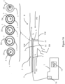
- FIG 1A an image data collection and processing system 1 is shown that is configured to interface with an optical fiber 3 that is part of a data collection probe 5.
- Figure 1B shows additional details relating to the image data collection and processing system 1 for an arrangement in which it is an OCT data collection and processing system.
- the probe 5 is shown in an in-vivo environment with respect to a blood vessel B having a vessel wall VW that defines a lumen L.
- the blood vessel B also includes a side branch SB.
- the probe 5 includes a probe tip which includes or is in optical communication with an optical fiber 3.
- the optical fiber 3 and the tip of the probe 5 are disposed within one or more sheaths such as catheter sheath 7.
- the probe tip can include various elements such as an angled beam director or a lens cap as well as transducers for other imaging modalities.
- the optical fiber 3 of the probe 5 can also include a torque wire disposed around the fiber 3.
- the probe transmits light, shown as ⁇ , in the lumen L and receives light scattered from the vessel wall VW.
- the optical fiber 3 can be a portion of a sample arm of an interferometer.
- a data collection probe 5 such as an OCT probe, can be used to collect depth information suitable for imaging a sample such as a blood vessel.
- a set of frames of image data such as frame F1 and frame F2 are generated based upon optical signals sent and received by such a probe 5.
- a cross-sectional image of blood vessel is formed by a collection of scan lines as the probe rotates.
- the probe 5 is pulled back through the blood vessel B as the fiber 3 and probe tip within sheath 7 rotates such that the beam of light ⁇ sent to the vessel wall from the probe tip traces a spiral as it moves along the section of the blood vessel B being imaged.
- This section has a specified pullback distance.
- a set of frames may be obtained with regard to the pullback distance.
- the probe 5 slides within the sheath 7 as it is pulled back through the blood vessel.
- different frames are obtained with regard to different sections of the blood vessel and through different sections of the sheath 7.
- frame F1 and frame F2 represent in Figure 3B and Figure 3C correspond to imaging through the sheath 7 at different locations and showing images generated with regard to different calibration features as a result of the different sections of sheath 7 being imaged.
- the sheath 7 may move and compress along the blood vessel B and have different elliptical cross-section that varies or move along the frames as shown in frames F1 and F2.
- Aspects of the disclosure relate to performing calibration of a plurality of frames of OCT data using a calibration feature 10 that changes across frames as well as calibration features that do not move across frames.
- a fiber fixed calibration feature 10a that is directly attached to the optical fiber 3 such as probe embodiment D1 of Figure 2A is different from a calibration feature in the imaging field that moves and changes as the probe 5 is pulled back such as calibration feature 10c in Figures 2C and 2D .
- the probe D1 includes a calibration feature that is attached to the optical fiber 3 as a concentric layer and thus moves with and is consistently imaged the same way by the probe D1.
- An image data collection probe 5 such as an OCT probe can include a calibration feature 10 that can be identified by one or more modules 12 of system 1 in frames of image data obtained during a pullback.
- the software modules 12 can include various calibration software modules, image processing software modules, graphic user interface, cross-sectional area display, longitudinal or L-mode display, a spline or interpolation software module, prefetch software module or architecture, and other software modules as described herein.
- the calibration feature 10 can include a geometric structure or pattern or controlled arrangement of backscattering particles to distinguish probe types and calibrate a data collection system when using a given type of data collection probe.
- the placement or properties of a given calibration feature can be used to identify different types of data collection probes.
- the specific calibration steps, such as steps 1-4 shown in Figure 4 that can be performed for a given catheter type can be specified upon identifying the type of catheter being used with an OCT system.
- the different calibration features 10a, 10b, 10c, and combinations thereof can be used as signatures to differentiate probe types and trigger probe specific calibration software routes.
- Different calibration modules can be stored in memory as part of software modules 12 used by the system 1.
- the optical fiber 3 interfaces with a patient interface unit 14 that includes a dock or coupler configured to receive an end face of optical fiber 3 or an optical fiber coupled to optical fiber 3.
- the PIU can include a tag reader such as an RFID reader to read tags attached to the probe 5.
- Information relating to calibration features such as the thickness or concentration of doped sheaths or layers of the probe can be encoded thereon.
- a data collection probe 5 can include a plurality of elongate nested layers or sheaths and an optical fiber 3 disposed therein.
- the data collection probe can include a calibration feature such as the calibration feature 10 and other specific examples of calibration features such as features 10a, 10b, 10c and others shown and discussed in more detail herein.
- the data collection probe 5 can include a plurality of surfaces that provide reflections that can be used to identify one or more components of a given type of data collection probe.
- the layers shown are typically elongate cylindrical objects such as sheaths that are disposed one inside of the other.
- a support material such as a potting material may surround an optical fiber 3 disposed along the longitudinal axis of the probe in various embodiments.
- An example of a fiber 3 having potting material 20 surrounding the fiber 3 and one or more sheaths is shown in Figure 1A with regard to cross-section option D1 of the probe 5.
- the data collection probe 5 may be an OCT probe.
- the probe 5 is generalized as shown because various different exemplary cross-sections for OCT probe configurations are possible.
- probe configurations having cross-sections such as the optional probe cross-sections D1, D2, D3, D4, D5, D6 are provided as examples of various sheath configurations and the associated variations in calibration techniques associated therewith. Additional details relating to the various probe configurations D1, D2, D3, D4, and D5 are discussed with regard to Figures 2A-2D and Figure 3A-3D .
- this disclosure relates to devices, probes, systems, components thereof and methods suitable for collecting data with respect to a sample such as a blood vessel such that a suitable image can be generated with respect to the sample.
- a sample such as a blood vessel
- components of the data collection system need to be identified and calibrated.
- identifying different types of data collection probes is of interest because as imaging systems such as OCT systems change over time and as probe designs changes, it is desirable know if the relevant features of a given imaging system can be used as well as if certain legacy probes are compatible with a given imaging system.
- FIG 2A-2D and Figure 3A Prior to discussing such features and cross-sectional configurations, in Figure 2A-2D and Figure 3A , it is useful to consider some additional details relating to system 1 when such a system is an OCT system.
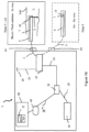
- FIG. 1B a generalized data collection and processing system 1 is shown.
- a data collection probe can be connected to the system 1 via various mechanisms such as optical coupler 22.
- the data collection probe 5 can be connected in air or ex vivo state and then inserted in a blood vessel having a lumen L.
- the system includes an interferometer having a reference arm and a sample arm.
- Optical fiber 3 is part of the sample arm of the interferometer.
- a reflector 25 such as a movable mirror on a track is part of the interferometer and specifies one terminus of the reference arm.
- the first optical coupler 22 may be in optical communication with a second optical coupler 31 via optical path 26.
- Light entering the first coupler 22 is the split along optical fiber paths 35 and 3.
- One path 35 terminates at a movable reflector 25, while sample arm portion enters probe 5 and allows light to be directed to the vessel wall VW at an angle relative to the longitudinal axis of the probe.
- probes 5 having different components such as back scattering doped sheaths or back scattering components can be used as calibration features.
- the optical patterns that are generated in a given image from a given probe are also types of calibration features.
- Light reflected by the movable reflector 25 passes back along optical fiber 35 to the coupler 22.
- light reflected by wall VW passes back along optical fiber 3 to the coupler 22 and combines with the light reflected by the movable reflector 25 to form an interference pattern.
- This combined light passes through optical path 26 to second coupler 31 to optical fiber 38 and is detected by a detector 40 such as a photodiode.
- the output signal from the detector 40 is processed by a processor or other components of an OCT system 50.
- the OCT system 50 may be a workstation or server configured to run software modules 12 and process frames or scan lines of image data corresponding to cross-sections of the blood vessel showing features of the vessel wall such as shown in Figures 3B and 3C for frames F1 and F2.
- the probe 5 includes or images one or more calibration features 10 during a pullback through a blood vessel, such as regions of light scattering particles that can be imaged and recognized using one or more software modules 12 and used to calibrate frames of image data.
- Contrast solution can flow through an annular region, a purge lumen defined by an inner layer, such as a first layer or first sheath, and an outer layer, such as a second layer or a second sheath as shown.
- this region can be air filled prior to use such as the ex vivo scenario shown in which the probe 5 is not disposed in the lumen L.
- the air is purged and a suitable solution such as a contrast solution or another solution fills one or more cavities or volumes in a given probe 5.
- T+ ⁇ T when the probe is in the lumen, the outer sheath of the catheter is adjacent a blood field in a blood vessel such as an artery in contrast with the outer sheath being adjacent to air at time T.
- the different air and fluid interfaces can be calibration features.
- the presence of air and a fluid in the catheter can be used during calibration because of the different optical propagation and reflections that occur based on which material is in the optical path during data collection.
- the interface between various sheaths and fluids and air changes as shown in the cross-sections of Figures 2A-2D and 3A depending on whether the probe is calibrated in air prior to insertion in a lumen or calibrated when in place.
- a purge lumen 70 is shown in the probes of Figures 2A-2C .
- the calibration features can include a scattering material arranged in a pattern such as a layer within a component of the probe.
- the scattering material may include TiO2.
- Fractional doped layers can also be selectively doped in one or more annular regions doped to form bands or regions of a sheath that scatter light.
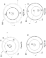
- Figures 2A, 2B, 2C, 2D , 3A , and 3B show various cross-sections of exemplary intravascular imaging probes D1, D2, D3, D4, D5, and D6 that include an optical fiber 3 and a sheath 7 having an outer sheath layer 7 o and inner sheath layer 7 i and calibration features or other properties suitable for performing calibration.
- Figure 2A depicts a cross-section of an intravascular imaging probe D1.
- Several substantially concentric layers surround an optical fiber 3.
- the optical fiber 3 is surrounded by a polymer layer 55 such as PET or another suitable polymer.
- polymer layer 55 is doped with light scattering particles.
- the light scattering particles in and of themselves may be a calibration feature 10a.
- This polymer layer 55 can be doped and shrunk onto the catheter lens to induce back reflection and generate a bright ring in a given image frame. Given the attachment to the lens, this calibration feature does not move across frames of image data.
- the light scattering particles together with the polymer layer 55 are a calibration feature 10a.
- a potting layer 20 may surround polymer layer 55 and optical fiber 3.
- the potting layer 20 can also be surrounded by another polymer layer 60.
- This additional polymer layer 60 can also include PET or another suitable material.
- This polymer layer 60 can be doped as a calibration feature as shown in Figure 2B .
- the outer sheath 7 o which is also typically formed from a suitable polymer, is the outer surface of the probe which typically interfaces with either air, prior to purging and insertion, or a flush solution during purging, or a flush solution such as contrast agent when disposed in a blood vessel. Purging the probe occur in the purge lumen 70.
- Each of the layers or structures shown in Figures 2A-2D are elongate sheath or optical cores.
- Figure 2B depicts a cross-section of an intravascular imaging probe D2 in which polymer layer 60 is doped to form calibration feature 10b.
- Other layers of a probe 5 such as layers 55 and sheath 7 can also be doped such as between inner sheath layer 7 i and outer sheath layer 7 o as shown by the calibration features 10c in probes D3 and D4.
- the optical fiber 3 is misaligned relative to center position C.
- optical fiber 3 is substantially in the center of potting layer 20.
- the probe includes a calibration feature disposed in sheath 7. Specifically, a region of the sheath is undoped UDS and has a thickness T1 and an index of refraction IR1.
- the sheath 7 is partially doped such that the doped portion of the sheath DS having a thickness T2 and an index of refraction IR2 is adjacent a flush zone 70 having an index of refraction IR3.
- the doped region of the sheath DS includes a concentration of scattering particles sufficient to scatter light for collection by a beam director or lens (not shown) and fiber 3.
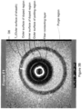
- Figures 3B and 3C show additional details relating to various layers of an exemplary data collection probe D6.
- Figure 3D show additional details relating to various layers of an exemplary data collection probe D7.
- Figures 3B and 3C show examples of an elliptical calibration feature that includes a second border disposed within a first border.
- the borders can include circles or rings in the image or borders or other calibration features.
- An OCT image such as the cross-sectional images of Figures 3B , 3C , and 3D are typically acquired one scan line at a time.
- a sequence of samples along a ray originating at the catheter center to the maximum imaging depth may be referred to as a scan line.
- the smallest data unit in an OCT image may be called a sample.
- a sequence of samples along a ray originating at the probe center to the maximum imaging depth is called a scan line.
- An OCT image is typically acquired one scan line at a time.
- a cross-sectional image can be formed from a set of scan lines collected as the probe rotates. Further, to image a segment of an artery or other vessel, the catheter is moved longitudinally while rotating.
- the probe acquires a set of cross-sectional images in a spiral pattern.
- the images originate from the various scan lines associated with a slice of the vessel or artery of interest.
- scan lines 1, 2 and 3 are illustrated with respect to Figure 3A .
- the scan lines are arranged with angles between them like spokes on a wheel.
- a cross-sectional image can be formed from a set of scan lines collected as the probe rotates. Further, to image a segment of an artery or other vessel, the catheter is moved longitudinally while rotating. In this way, the probe acquires a set of cross-sectional images in a spiral pattern. For a given scan line, a region of scattering can be a linear segment on the line.
- Various filters can be configured to be matched on a per scan line basis to identify regions of interest such as doped or backscattering regions and undoped or substantially non-scattering regions.
- the software modules described herein may be configured to operate or process a sample, a combination of samples as a scan line or a portion or a subset thereof, a combination of scan lines such as frame or a portion or a subset thereof and combinations of the foregoing.
- continuous calibration may be performed using samples or combinations of samples as scan lines.
- the resultant two and three dimensional images originate from the various scan lines associated with a slice of the vessel or artery of interest.
- the image can be displayed as cross-sections, such as in Figure 3A-3D .
- the combination of cross-sectional images allow a tomographic image such as the three-dimensional perspective views or two-dimensional longitudinal views to be displayed using software modules that operates on or otherwise transforms the OCT data acquired during a pullback.
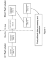
- Figure 4 and 5 illustrate a high level summary of events for various types of calibration.
- a disposable data collection probe is connected to a patient interface unit (step 1).
- Connection calibration can include a search of a range of the motor used to move the reference mirror to locate the catheter to detect scan line inversion.
- the frequency aliasing that occurs and can result is performed at the connection calibration and as part of the continuous calibration.
- the auto calibration also uses a process to compensate for image inversion or bowing as a result of frequency aliasing.
- the sweep range of the motor is reduced such as a sweep window of a few millimeters as the length of the fiber does not change after reaching equilibrium after being inserted in a blood vessel prior to pullback.
- the light propagates through one or more transparent sheaths that comprise the catheter outer structure.
- Each of the interfaces can cause a reflection that will be detected by OCT. Hence, it may be challenging to determine which of those reflections corresponds to the desired optical reference point.
- optical path lengths for a reference arm and sample arm of the interferometer used in the system need to be maintained within certain limits for interference to occur. This can be achieved using a translatable mirror on a track or otherwise driven in a linear manner. In this way it is possible to adjust reference arm position to align the distal tip of catheter with optical path length in the reference arm.
- Optical index and expansion can change optical path length in body.
- Various indexes of refraction (IR) are shown in Figure 3A as well as different media (blood, flush, air, etc.).
- the media in which the catheter is disposed change given the time outside a patient, the flush stage, the pullback, and again at removal.
- the reference mirror can be moved to match the path length change as part of an auto calibration process. This may be performed before pullback.
- the calibration method is implemented as computer-based algorithm such as various steps and loops with different phases or stages.
- the calibration method may determine the type of data collection probe attached to the system bases on the presence or absence of certain features in the images generated using data collected by a given probe.
- the method identifies a light scattering calibration feature such as a calibration feature disposed in the probe such as a doped layer.
- the calibration feature may be disposed near the optical fiber such as by being adjacent to the optical fiber in a material contacting an out surface of the optical fiber.
- the calibration software module is configured to change the underlying data such that it is passed through the image data processing pipeline in a changed state. Other modules append their changes without changing the underlying data and are passed to the next image processing module with the image data and information and changes from a proceeding pipeline module.
- connection calibration is performed to obtain data about the catheter from a scan of the doped sheath.
- the scanning for calibration can be at first rate of rotation.
- the system can determine which version of the catheter is being connected to the PIU.
- one catheter includes a doped layer that is disposed next to the optical fiber disposed in the sheath (see Figure 2A ).
- another catheter includes a doped version of the sheath (see Figure 2D ). The sheath is separated from, but substantially coaxial with, the longitudinal axis of the optical fiber.
- a probe, such as probe 5 in Figure 1A , having a rotatable optical fiber 3 is then inserted into the patient (step 3).
- a temperature calibration process that is performed in vivo to compensate for temperature effects on the length of the optical fiber 3 (step 4).
- the temperature calibration can be implemented using movement of the reference mirror such as was done with regard to connection calibration (step 2).
- the temperature calibration typically takes a shorter period of time relative to the connection calibration.
- pullback is enabled (step 5). This step can include monitoring relating to the image data from the probe and preparing a flush. A pullback is then triggered either automatically or manually (step 6). A blood clearing detection method can be used to trigger a pull back after a flush sufficiently clears the lumen.
- OCT data received from the catheter can be saved in various formats such as a multipage TIF file format.
- Each TIF file includes multiple frames of data.
- the scan lines are acquired in a polar format in one embodiment and stored in the TIF file.
- Each frame is a cross-section of a blood vessel or other sample.
- the software-based continuous calibration method operates on the frames and aligns the catheter in each frame relative to the catheter in other frames by identifying a boundary such as a ring or doped sheath and making adjustments as to the catheter's position on a per frame basis.
- Continuous calibration may be one image processing module or a plurality of image processing modules arranged in path or graph of a particular processing order.
- the pattern can be a sequential arrangement modules that is been next that is been experimentally determined to improve quality of the OCT data for particular image frame or otherwise improve the operation downstream image processing modules.
- the pattern or order of the sequence in which image processing modules are arranged can also be determined based on physiological considerations such as the interplay of a guide wire, guide wire shadows, a guide catheter, the side branches disposed in the blood vessel, stent strut detection, position of the lumen border, the detection the lumen such as by the luminal border, plaque detection or other physiological segmentation of a blood vessel, stent malaposition, in the display of two-dimensional views of a vessel such as a longitudinal view or L mode or a cross-sectional view. Additional details relating to the arrangement of image processing software modules or possible processing pathways between such modules is provided in Figure 8 .
- the images / frames are modified by first establishing a threshold for background noise or otherwise performing a thresholding process (step 7).
- a thresholding process Under the multi-frame architecture, prior frames are delivered to the thresholding algorithm to determine a threshold that will not result in too much noise in the cleared lumen or too many "drop outs" (blank areas) in the lumen boundary.
- the thresholding process can be implemented in one, two, three or more stages. Various thresholding algorithms can be used as is known in the art.
- a continuous calibration process is started place to continually calibrate the diameter or position of the catheter using frames acquired as it was pulled through the lumen (step 8).
- the calibrate frames are then used in calibrated form for the other modules in the pipeline.
- guidewire detection is performed (step 9) and in the future, guide catheter detection will be performed (step 10).
- side branch detection is performed (step 11) and stent strut detection (step 12) can be performed.
- image data from the pullback is stored in memory such as in a cache.
- the image data is then distributed to the individual modules for analysis or modification.
- Single frame detection and processing can be performed on the image data in one embodiment on a per module basis.
- the data is sent to memory storage, such as a server or hard disk, so that the individual software modules or algorithms can request and receive previous frames of OCT image data.
- the system searches for stent struts (step 12) and then determines the lumen location (step 13). Plaque detection, stent malapposition detection, or other tissue characterization can then be performed (steps 14a and 14b step 17). 2D or 3D display is then performed (step 15) using the processed OCT image data.
- Ellipse detection algorithms can be used to identify one or more sheath boundaries or interfaces between the flush solution region, blood, or one or both of the sublayers. This information can be used to align the catheter on a per frame basis. The direction of motion of the reference mirror and its speed can be used to compensate for frequency alias effects.
- the reference mirror may be set at a home position. This is typically performed before a pullback as part of an autocalibrate step. Next, it is swept or scanned in the forward direction to a first position. A course adjustment scan can then be performed in the backward direction beyond where it needs to be (to remove hysteresis). A fine adjustment is then made in the direction of the original sweep. Next using the scan lines obtained for a given frame, the software-based system attempts to find a partial layer or full layer of scattering particles in the sheath or catheter.
- an OCT probe has a rotatable fiber disposed in one or more sheaths
- such sheaths can be doped with one (see Figures 2A-3D and as otherwise described herein) or more layers (or sublayers) (see Figure 2B ).
- a dopant layer on or in the sheath can be selected to reduce unwanted reflections while being detectable by software as a calibration feature.
- the calibration feature can include a doped sheath that is selectively doped with scattering particles.
- the sheath is a type of elongate substantially curved cover having an optical fiber disposed therein. Such a sheath typically has an elliptical cross section which includes a circular cross-section.
- the software can be configured to identify a given catheter based on its components or calibration features.
- the software performs various filtering, detecting, and thresholding steps to identify the sheath such as by a particular pattern or other characteristic on each frame.
- a filter can include a stepwise function with notches sized to pick up elements along a scan line such as a thickness of doped region.
- a given filter can be represented as a matrix or other operator.
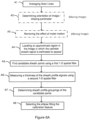
- Step 6A Various steps for locating a calibration feature such as a intense region in the image, a border or interface, an annular region, an irregular shape or other suitable features in an OCT image are described in Figure 6A .
- the software and systems described herein can use various processing steps (Steps A1-A8) and software modules to identify a doped sheath.
- Various physical constraints can be to facilitate its detection in an OCT frame.
- the doped sheath is typically circular or elliptical.
- the sheath can deform and twist in a vessel although its overall area or perimeter should not change across frames.
- the doped sheath is generally not disposed in the center of the blood vessel, but rather can move around in various non-concentric positions. These geometric limitation can be used to estimate areas where the sheath appears.
- the thickness of the doped sheath can vary based upon manufacturing tolerances.
- the dope sheath is susceptible to speckle as shown by the dark regions in the left side of Figure 6B in contrast with the version shown to the right in which line averaging has been performed. All of these factors present challenges to tracking the doped sheath as a calibration feature.
- Steps A1-A8 can be used one or more times to identify a given calibration feature.
- Filters can be used together or separately in one embodiment.
- the steps include averaging scan lines A1, locating an approximate region in the image in which the catheter sheath signal is estimated to appear A4, finding candidate sheath points using one or more filters such as a 1-D filter kernel A5, measuring a thickness of the circular or elliptical signals using a second filter such a 1-D spatial filter A6, determining circular; likely off-center, groupings of the candidate points A8, and selecting an ellipse A8.
- the images are moving steps A2 and A3 can also be performed.
- a first filter may be used.
- the first filter can be configured to work in various possible case (in-vivo/ex-vivo and across the entire doped layer thickness).
- the filter is selected to deal with the scenarios that the probe and the calibration feature will be exposed to in use.
- One or more filters may be configured to address the following circumstances or parameters:
- the system or a calibration module may try to search for a doped sheath or ring next to the fiber 3 such as would be present in Figure 2A .
- the lack of a doped sheath can be an indication that a different type of catheter is being used, but is not determinative. If the system cannot find a doped layer or ring near the fiber, an error signal is generated. If this system finds and loses or cannot find a calibration feature it can mark the data as unusable or generate an operator alert.
- Figure 2A depicts one catheter type and Figures 2C and 2D depict show various features of two catheter types.
- the system is configured to identify these types and others.
- the system looks for a doped sheath first and absent finding that looks or a doped ring near the fiber. This is performed as part of the auto calibrate before a pullback is performed.
- catheter type informs how data can be processed in the modular image processing pipeline.
- the catheters are designed to work with a flush solution which fills the region between the fiber and the sheath. This helps prevent blood ingress and is used to flush a lumen for OCT imaging during a pullback.
- the solution is configured to provide a suitable level of index matching between the fiber and the sheath.
- the doped sheath When the probe is in air, the doped sheath is easier to locate relative to when it is in blood. The doped sheath resembles tissue to a greater degree when compared to a PET ring near the fiber.
- multi-threshold sampling can be performed to identify candidates for the doped sheath. These can be scored and when a sufficient number of samples indicate a suitable probability that a dope sheath exists, that sheath position is used for a given frame.
- Figure 7 depicts an image data processing architecture suitable for processing scan lines, samples or frames obtained using an intravascular imaging probe. Initially frames from the pullback of the probe are provided as an input for first image data processing module, shown here in Figure 7 as image data processing module A.
- image data processing module A first image data processing module
- the steps and processes described herein can be configured to operate at the sample, the scan line, the frame, or the set of frames level in a given arrangement.
- reference to one of the foregoing types of OCT data can be changed to another of the types of OCT herein without limitation.
- a reference to a frame also contemplates the relevant arrangement operating on a scan line and vice versa.
- all of the calibration, processing, and filtering steps described herein are performed with respect to scan lines.
- the image data processing module may be configured to operate on frames from the pullback such as Frame 1, Frame 2 and Frame 3 shown. Each frame is received by the image processing module A as part of the first pass during which module operates on each frame and generates an output for each frame. For Frame 1 the output is output A1 for Frame 1, for Frame 2 the output is output A2 for Frame 2, and for Frame 3 the output is A3 for Frame 3.
- Each of the outputs can be a value such as a possible value used to shift pixels in a frame or sample in scan line consistent with making a sample path and reference path length substantially the same or aligning or detecting a calibration feature in different frames or scan lines.
- the outputs can be operators themselves such as matrices for application to other frames and other image processing modules.
- module A is one of the modules shown in Figure 8 and module B, is another module from Figure 8 .
- the first pass performed with respect to module A may be a prefetch.
- Image processing module A may receive a frame or a plurality of scan lines from a pullback and processes the frames or scan lines generates frame or scan line outputs.
- the second pass can be the application of the output such as output A3 applied to Frame 3 shown in the second pass, with dotted frames.
- These process frames are then provided in image data processing module B and each frame is operated upon as shown as part of a first pass such that outputs B1, B2, and B3 are generated. As shown, these outputs are applied to the input frames to module B such that the resulting frames are Frame 1 with B1 applied, Frame 2 with B2 applied, and Frame 3 with B3 applied.
- the operation applied by module A carries through to the output frames by module B shown in the top right corner of Figure 7 unless, for example, module B is configured to undo some or all of the operations of the module A.
- module A may be configured to provide continuous calibration on a set of frames received from a pullback. As a result, following the application of module A, the frames would be calibrated. Further, module B would advantageously receive calibrated frames prior to the application of any additional image processing, such as, for example, shadow removal lightening or guide wire detection.
- any additional image processing such as, for example, shadow removal lightening or guide wire detection.
- one aspect of the disclosure relates to a multiple prefetch architecture.
- calibration results may be computed with regard to a first prefetch of frames of image data to be displayed or processed by a second prefetch of frames of image data.
- Raw unprocessed image data can be displayed from a pullback as a second stream of image data is processed according to the image processing pipeline described herein.
- the use of two frames helps to increase the accuracy of detecting the lumen boundary.
- a guidewire casts a shadow obscuring part of the boundary.
- a scan line can also be blocked by uncleared debris or blood in the lumen as shown.
- the scan line may image multiple points of occlusion.
- this debris tends to be small, and hence, by looking at previous frames, the software can be used to determine that because the wall has continuity between frames, while the debris will not, debris can be distinguished from wall.
- Performing two passes on image data frames allows all of the operations of a give module, such as module A in Figure 7 to be performed and cached. These can be kept as an array or applied to the set of frames from the pullback.
- the set of modified frames or frames and such an array can then be passed to subsequent image data processing pipeline module, such as module B.
- Module A and module B can be any of the software modules selected from image processing software pipelines shown in Figure 8 .
- the prefetching of data for one image data processing module from either a set of images obtained from an imaged data collection pullback, whether OCT, IVUS, or otherwise can be used as inputs to one or more of the processing paths of Figure 8 .
- One or more of the paths spanning Figure 8 can be selected based on processing resources and the outputs of interest to a user.
- Continuous calibration may refer to a software-based calibration by which the catheter or optical fiber in each frame is aligned between frames.
- the pipeline software modules are arranged in a tree structure based on physiological and data processing constraints as shown in Figure 8 .
- the physiology and data input can lead to a preferred order for modules in the pipeline. In some instances, the order improves results or makes certain outputs possible, such as lumen detection.
- the selection of the order of swappable encapsulated software modules and the benefits of continuous calibration lead to improved data processing results and efficiencies.
- the software modules can be configured to be swappable and are configured to be encapsulated relative to each other to reduce the likelihood of error propagation and to enable swapping of modules and changes to processing order for frames.
- Stages of the image data pipeline are sequenced to improve resolution and avoid errors based on physiological constraints and a multi-stage calibration routine.
- the algorithm may have two phases. The first phase runs during a prefetch to collect potential guide wire regions, while, the second phase is executed if the pullback has multiple frames. The first phase runs as a single frame process, which gathers information for each frame. The second phase is executed as a multiple frame process, which uses the information from single frame process in one embodiment.
- the multi-frame system uses two or more passes to improve accuracy and reduce noise.
- One pass operates on and analyzes frames and generates corrective values or other outputs based on module operating.
- Calibration is selected as first image data processing module.
- the first pass through the calibration module identifies radial or other distances by which the image needs to be shifted to align optical fiber received signal between frames.
- Lumen detection is later in the pipeline because it is dependent on guidewire detection, side branch detection, and stent strut detection happening before it in the pipeline, in one embodiment.
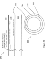
- FIG 9A a portion of an intravascular imaging probe is shown.
- the probe includes a beam director 180 that is adjacent to a section of optical fiber 190 that includes a glass section.
- Two fusion splices further in the probe can create a low intensity region as shown by the irregular region in the lower section of Figure 9A . Since this region corresponds to a section of glass, light should pass through without excessive scattering.
- rings can easily form in an image as a result of the probe's substantially circular cross-section and many components. Rings of this nature, which can be produced by catheters, splices and other optical components of an imaging system, can interfere with calibration. For example, such rings can be locked on and erroneously processed as a calibration feature.
- Known intensity regions such as the splice region shown, and other regions in the image can be used to exclude certain signals, such as rings, as candidates for a calibration feature, when such features are being sought after.
- a known low intensity region in an image frame based on probe components and their arrangement, can be used to improve calibration efficiency and exclude erroneous rings and other artifacts.
- Figure 9B shows a manufacturing problem that causes a related imaging artifact.
- the optical fiber 195 shown is disposed in a layer that is adhered to the fiber. This is in contrast with a calibration feature in the imaging field with respect to which a probe can move relative to in a given embodiment.
- the off-center placement of the fiber can lead to additional calibration steps. Since distance X and Y differ, when rotating, the distances recorded as scan lines are off by an amount that can skew results and impact subsequent image processing. As a result, other calibrations features can be used to compensate for this result.
- the continuous calibration features described herein can include a periodic tracking of cross-sectional images.
- a loss of lock on a calibration feature during a given calibration feature can be used to stop an imaging procedure or to otherwise alert an operator.
- a loss of lock or tracking with respect to a calibration feature can trigger an alert or inform an operator that the pullback data cannot be used.
- the threshold can include a loss of lock over a predetermined number of frames or a predetermined time period.
- a set of frames of image data are generated based upon optical signals sent and received by an optical coherence tomography data collection probe.
- the probe includes a probe tip which includes or is in optical communication with an optical fiber.
- the probe is pulled back through the blood vessel as it rotates such that the beam of light sent to the vessel wall from the probe tip traces a spiral as it moves along the section of the blood vessel being imaged.
- This section has a specified pullback distance D.
- a set of frames are obtained with regard to the pullback distance D.
- an ellipse can be fit to a doped layer disposed relative to the sheath such as in or within or exterior to the sheath.
- This doped layer is used for various purposes such as different calibration routines. If such an ellipse fitting fails, or if the resulting ellipse fit is computed erroneously relative to the location of the doped layer, the resulting fit can be considered discarded or ignored during subsequent calibration processing steps.
- the polymer sheath in which the probe is disposed during the pullback generally has an elliptical cross-section.
- the optical fiber of the probe and the sheath are visible or detectable in frames of image data.
- this cross-section is circular.
- the sheath can be curved or folded such that from a cross-sectional perspective the perimeter of the sheath ranges over various regular or irregular continuous curves.
- various parameters such as the perimeter of a given sheath should be the same or substantially the same across frames obtained along the pullback distance. As a result, even if the sheath deforms from an ellipse to an irregular contour the perimeter should be constant or substantially constant between frames.
- the perimeter may be estimated based on the best fit ellipse. In other arrangements the perimeter may be computed directly from the computed offsets and this might be more accurate, although it might be more prone to noise in certain circumstances.
- the mean diameter of the sheath can be used as another metric which should generally remain constant between frames.
- the position of the optical fiber can also be tracked across frames.
- One or more calibration software modules may be used to perform the spline-based or elliptical fitting described herein. The software modules can be configured to include constraints to prevent discontinuities and jumps between frames.
- eccentricity of ellipse a parameter that can be tracked including without limitation: eccentricity of ellipse, center position of ellipse, perimeter of ellipse, and perimeter of offsets.
- Eccentricity of ellipse - if eccentricity varies wildly from one frame to a next, that could indicate an error in ellipse fit and thus be an outlier.
- Perimeter of offsets is potentially more accurate as a calibration metric than perimeter of ellipse, but this could also be subject to errors based on false offset detections that are essentially ignored by ellipse fit.
- an ellipse can be fit to the sheath or scattering particles disposed therein for a given frame, the frame is likely to be useful for calibration and imaging.
- This elliptical fitting is used as part of one or more calibration routines.
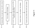
- Such elliptical fitting on spline-based fitting may be performed using one or more steps as outlined in Figure 11 .
- Offsets are computed for each line within a frame, the ellipse is fit to the offsets.
- a size value for the ellipse such as a mean diameter or mean radius of the ellipse is saved as an offset value for a given frame.
- All frames in the pullback are partitioned into 1 mm discrete windows. The median offset within each window, based on the per frame offset values, is used as the value for fitting the spline.
- the spline effectively models the offset for all frames, and due to the median being used on each window, outlier offsets are effectively ignored. Because the spline fit will be smooth, it is a suitable value to use for calibration. The spline does not select frames to be displayed. The spline does effectively interpolate offset values for frames on which the offset detection failed or for which the detected offset was computed erroneously (an outlier).
- interpolation refers to the process of extracting suitable calibration correction values for frames on which offsets could not be computed by using the valid offsets from surrounding frames in which the offsets are computed correctly.
- the data fitting of frame of image data may be performed using a spline or spline fitting based method.
- the inputs of the data fitting algorithm for continuous calibration may be inputs are the median offset values computed on each 1 mm window in the pullback.
- the parameters are the median offset values computed in each window of size 1 mm along the pullback. Performing a polynomial fit relative to a set of values obtained for the different windows that is representative of the ellipse such as its size or position is used to test the likelihood that the ellipse has been found. If the fit of the ellipse parameter is consistent over the windows, this supports the position that the correct feature has been identified in each image frame.
- the fitting process performs a fit with regard to the offset values such as an ellipse size value or parameter that are computed for each frame. If spline algorithm or continuous calibration otherwise does not work for a particular reason, the software is configured to direct the user to the manual verification/adjustment screen.
- the probe image is provided to the user for manual selection or to provide a set of candidates for the user to evaluate or request more information from the user.
- An inner layer, a middle layer, or an outer layer of the probe can be doped.
- Two closely-spaced layers can be used to provide a double-line reflection. These double layers can be disposed in the sheath or outer layer of the probe in one embodiment.
- the double-line reflection configuration can be used to mitigate spurious reflections.
- a data collection probe can include two layers having a space in between the doped material in separate components, rather than two layers within the same component.
- a combination of components with either full-wall thickness of doped material such as a PET layer around near the optical fiber
- doped layer(s) such as the window tubing with doped inner-layer
- a combination of doped rings can be used in such a manner, for example: doped lens PET and doped window tubing - each with doped full-wall (not layered), or one or both with a doped layer(s) can be used for some data collection probe embodiments.
- the flexible sheath through which light passes to and from the probe tip may be made from a thermoplastic material.
- a thermoplastic material is a polyether-polyamide block copolymer.
- a partially doped sheath can be achieved using various plastic materials that can be formed or molded into a tube or other shape.
- the doped layer may be disposed within the sheath and has a thickness that ranges from about 0.001 inches to about 0.004 inches.
- a substantially scattering particle free layer may be disposed within the sheath and has a thickness that ranges from 0 to about 0.004 inches.
- the probe includes a substantially transparent curved cover defining a first bore and comprising a polymer, the substantially transparent curved cover comprising a substantially elliptical cross section comprising a first annular region having a first annular thickness T1 and a second annular region, the second annular region doped with a light scattering material and having a second annular thickness T2, the first annular region substantially free of the light scattering material; a beam director; a torque wire defining a second bore; a rotatable optical fiber in optical communication with the beam director, the rotatable optical fiber disposed in the second bore, the torque wire slidably disposed within the first bore.
- an exemplary sheath 200 is illustrates a magnified view 210 of various interface layers for the sheath 200.
- the interface layers include the outer layer or outer diameter of the sheath identified as OD.
- One layer 215 of sheath 200 is substantially free of light scattering particles as a dopant and has a thickness T1.
- One layer 220 of sheath 200 includes light scattering particles as a dopant and has a thickness T2.
- the doped sheath used for a particular calibration feature may be adjusted to account, for OCT resolution.
- the OCT resolution cell in the sheath 200 is smaller (better) than the resolution in air by 1/n-material, where n-material is the index of refraction of the material.
- the sheath 200 is a polymer, and most polymers have an index of ⁇ 1.5.
- 8-20 um resolution in air is a ⁇ 12.5 um resolution cell in the polymer of the sheath 200.
- the clear layer, later 215, may appear thinner by one resolution cell than actual while the doped layer 210 appears thicker by one resolution cell than actual under OCT.
- This yields the desired ratio of 1:1, apparent layer thicknesses. (37.5+12.5 62.5 - 12.5).
- the ratio of T1 and T2 may range from greater than about zero to 1.
- the boundary between the DS and UDS regions may be a calibration feature.
- the ratio of T2 to T1 may be about 1 : 5, about 3 : 5, or about 4 : 6.
- the thickness of the sheath 200 may be T1 +T2.
- T1 + T2 may be about 60 ⁇ m, about 100 ⁇ m, about 120 ⁇ m, about 140 ⁇ m, about 160 ⁇ m, about 180 ⁇ m or about 200 ⁇ m.
- the light scattering material comprises titanium dioxide.
- the calibration feature may include an arrangement of light scattering particles that are sized and positioned such that single scattering is maintained with respect to incident light.
- a multiple scattering threshold may be set as constraint when disposing scattering particles in a given elongate layer or film of a data collection probe. This follows because attenuation will increase rapidly while return signal (doped layer brightness) will not increase as much.
- each term includes all wavelength (and frequency) ranges and individual wavelengths (and frequencies) in the electromagnetic spectrum.
- device and apparatus are also used interchangeably.
- a source of electromagnetic radiation is a laser.
- a laser is a device or system that produces or amplifies light by the process of stimulated emission of radiation.
- some non-limiting examples of lasers suitable for use in the described arrangements can include tunable lasers (sometimes referred to as swept source lasers), superluminescent diodes, laser diodes, semiconductor lasers, mode-locked lasers, gas lasers, fiber lasers, solid-state lasers, waveguide lasers, laser amplifiers (sometimes referred to as optical amplifiers), laser oscillators, and amplified spontaneous emission lasers (sometimes referred to as mirrorless lasers or superradiant lasers).
- the following description is intended to provide an overview of device hardware and other operating components suitable for performing the methods described herein. This description is not intended to limit the applicable environments. Similarly, the hardware and other operating components may be suitable as part of the apparatuses described above.
- the invention can be practiced with other system configurations, including personal computers, multiprocessor systems, microprocessor-based or programmable electronic device, network PCs, minicomputers, mainframe computers, and the like.
- the invention can also be practiced in distributed computing environments where tasks are performed by remote processing devices that are linked through a communications network such as in different rooms of a catheter or cath lab.
- aspects of the disclosure also relates to apparatus for performing the operations herein.
- This apparatus may be specially constructed for the required purposes, or it may comprise a general purpose computer selectively activated or reconfigured by a computer program stored in the computer.
- aspects of the disclosure may be embodied in many different forms, including, but in no way limited to, computer program logic for use with a processor (e.g., a microprocessor, microcontroller, digital signal processor, or general purpose computer), programmable logic for use with a programmable logic device, (e.g., a Field Programmable Gate Array (FPGA) or other programmable logic device), discrete components, integrated circuitry (e.g., an Application Specific Integrated Circuit (ASIC)), or any other means including any combination thereof.
- a processor e.g., a microprocessor, microcontroller, digital signal processor, or general purpose computer
- programmable logic for use with a programmable logic device, (e.g., a Field Programmable Gate Array (FPGA) or other programmable logic device), discrete components, integrated circuitry (e.g., an Application Specific Integrated Circuit (ASIC)), or any other means including any combination thereof.
- FPGA Field Programmable Gate Array
- ASIC Application Specific Integrated
- some or all of the processing of the data collected using an OCT probe and the processor-based system is implemented as a set of computer program instructions that is converted into a computer executable form, stored as such in a computer readable medium, and executed by a microprocessor under the control of an operating system.
- query response and input data are transformed into processor understandable instructions suitable for generating one or more or prefetches, calibration corrections, offsets, detecting lumen borders, comparing measured perpendicular distances relative to set thresholds, and otherwise performing image comparison, thresholding, signal processing, pattern matching, artifact removal, continuous calibration, and other features described above.
- Source code may include a series of computer program instructions implemented in any of various programming languages (e.g., an object code, an assembly language, or a high-level language such as Fortran, C, C++, JAVA, or HTML) for use with various operating systems or operating environments.
- the source code may define and use various data structures and communication messages.
- the source code may be in a computer executable form (e.g., via an interpreter), or the source code may be converted (e.g., via a translator, assembler, or compiler) into a computer executable form.
- the computer program may be fixed in any form (e.g., source code form, computer executable form, or an intermediate form) either permanently or transitorily in a tangible storage medium, such as a semiconductor memory device (e.g., a RAM, ROM, PROM, EEPROM, or Flash-Programmable RAM), a magnetic memory device (e.g., a diskette or fixed disk), an optical memory device (e.g., a CD-ROM), a PC card (e.g., PCMCIA card), or other memory device.
- a semiconductor memory device e.g., a RAM, ROM, PROM, EEPROM, or Flash-Programmable RAM
- a magnetic memory device e.g., a diskette or fixed disk
- an optical memory device e.g., a CD-ROM
- PC card e.g., PCMCIA card
- the computer program may be fixed in any form in a signal that is transmittable to a computer using any of various communication technologies, including, but in no way limited to, analog technologies, digital technologies, optical technologies, wireless technologies (e.g., Bluetooth), networking technologies, and internetworking technologies.
- the computer program may be distributed in any form as a removable storage medium with accompanying printed or electronic documentation (e.g., shrink-wrapped software), preloaded with a computer system (e.g., on system ROM or fixed disk), or distributed from a server or electronic bulletin board over the communication system (e.g., the Internet or World Wide Web).
- Hardware logic including programmable logic for use with a programmable logic device
- implementing all or part of the functionality previously described herein may be designed using traditional manual methods, or may be designed, captured, simulated, or documented electronically using various tools, such as Computer Aided Design (CAD), a hardware description language (e.g., VHDL or AHDL), or a PLD programming language (e.g., PALASM, ABEL, or CUPL).
- CAD Computer Aided Design
- a hardware description language e.g., VHDL or AHDL
- PLD programming language e.g., PALASM, ABEL, or CUPL
- Programmable logic may be fixed either permanently or transitorily in a tangible storage medium, such as a semiconductor memory device (e.g., a RAM, ROM, PROM, EEPROM, or Flash-Programmable RAM), a magnetic memory device (e.g., a diskette or fixed disk), an optical memory device (e.g., a CD-ROM), or other memory device.
- a semiconductor memory device e.g., a RAM, ROM, PROM, EEPROM, or Flash-Programmable RAM
- a magnetic memory device e.g., a diskette or fixed disk
- an optical memory device e.g., a CD-ROM
- the programmable logic may be fixed in a signal that is transmittable to a computer using any of various communication technologies, including, but in no way limited to, analog technologies, digital technologies, optical technologies, wireless technologies (e.g., Bluetooth), networking technologies, and internetworking technologies.
- the programmable logic may be distributed as a removable storage medium with accompanying printed or electronic documentation (e.g., shrink-wrapped software), preloaded with a computer system (e.g., on system ROM or fixed disk), or distributed from a server or electronic bulletin board over the communication system (e.g., the Internet or World Wide Web).
- printed or electronic documentation e.g., shrink-wrapped software
- a computer system e.g., on system ROM or fixed disk
- server or electronic bulletin board e.g., the Internet or World Wide Web
- a module refers to software, hardware, or firmware suitable for performing a specific data processing or data transmission task.
- a module may refer to a software routine, program, or other memory resident application suitable for receiving, transforming, routing and processing instructions, or various types of data such as OCT scan data, kernel filters, filters, thresholding, pattern matching, interferometer signal data, guide wire locations, shadow region locations, side branch locations, side branch diameters, intensity profiles, and other information of interest.
- Computers and computer systems described herein may include operatively associated computer-readable media such as memory for storing software applications used in obtaining, processing, storing and/or communicating data. It can be appreciated that such memory can be internal, external, remote or local with respect to its operatively associated computer or computer system.
- Memory may also include any means for storing software or other instructions including, for example and without limitation, a hard disk, an optical disk, floppy disk, DVD (digital versatile disc), CD (compact disc), memory stick, flash memory, ROM (read only memory), RAM (random access memory), DRAM (dynamic random access memory), PROM (programmable ROM), EEPROM (extended erasable PROM), and/or other like computer-readable media.
- a hard disk an optical disk, floppy disk, DVD (digital versatile disc), CD (compact disc), memory stick, flash memory, ROM (read only memory), RAM (random access memory), DRAM (dynamic random access memory), PROM (programmable ROM), EEPROM (extended erasable PROM), and/or other like computer-readable media.
- computer-readable memory media applied in association with aspects described herein may include any memory medium capable of storing instructions executed by a programmable apparatus. Where applicable, method steps described herein may be embodied or executed as instructions stored on a computer-readable memory medium or memory media. These instructions may be software embodied in various programming languages such as C++, C, Java, and/or a variety of other kinds of software programming languages that may be applied to create instructions in accordance with embodiments of the invention.
- a storage medium may be non-transitory or include a non-transitory device. Accordingly, a non-transitory storage medium or non-transitory device may include a device that is tangible, meaning that the device has a concrete physical form, although the device may change its physical state. Thus, for example, non-transitory refers to a device remaining tangible despite this change in state.
- compositions are described as having, including, or comprising specific components, or where processes are described as having, including or comprising specific process steps, it is contemplated that compositions of the present teachings also consist essentially of, or consist of, the recited components, and that the processes of the present teachings also consist essentially of, or consist of, the recited process steps.
- each intervening value between the upper and lower limits of that range or list of values is individually contemplated and is encompassed within the invention as if each value were specifically enumerated herein.
- smaller ranges between and including the upper and lower limits of a given range are contemplated and encompassed within the invention.
- the listing of exemplary values or ranges is not a disclaimer of other values or ranges between and including the upper and lower limits of a given range.
- a single component may be replaced by multiple components, and multiple components may be replaced by a single component, to provide an element or structure or to perform a given function or functions. Except where such substitution would not be operative to practice certain embodiments of the invention, such substitution is considered within the scope of the invention.
Claims (13)
- Procédé mis en oeuvre par ordinateur pour traiter une pluralité de trames comprenant chacune une image en coupe transversale collectée pendant un retrait d'une sonde sur une distance D à travers un vaisseau sanguin, comprenant :la collecte de la pluralité de trames à l'aide d'une sonde optique (5) tirée vers l'arrière par rapport à une gaine allongée (7) ayant une coupe transversale elliptique, la gaine allongée ayant une région dopée (DS) qui a une première épaisseur (T2), la région dopée étant dopée avec une pluralité d'éléments de diffusion de manière à fournir une caractéristique d'étalonnage elliptique, la gaine allongée ayant également une région non dopée (UDS) qui a une seconde épaisseur (T1), la région dopée et la région non dopée étant des régions annulaires de la gaine allongée (7), la région dopée étant disposée de manière concentrique à l'intérieur de la région non dopée ; etl'étalonnage de la pluralité de trames en identifiant dans au moins une majorité des trames la caractéristique d'étalonnage elliptique qui change entre deux des trames ou plus le long de la distance D, et en suivant la caractéristique d'étalonnage elliptique à travers la pluralité de trames.
- Procédé selon la revendication 1, dans lequel la région dopée et la région non dopée sont situées entre une couche interne de la gaine allongée (7i) et une couche externe de la gaine allongée (70), la région dopée étant adjacente à une zone affleurante (70) à l'intérieur de la gaine allongée.
- Procédé selon une quelconque revendication précédente, comprenant en outre la division de la pluralité de trames en une pluralité de fenêtres, et l'ajustement d'une courbe par rapport à une mesure de la caractéristique d'étalonnage elliptique à travers la pluralité de fenêtres.
- Procédé selon une quelconque revendication précédente, comprenant en outre l'alignement de la caractéristique d'étalonnage ou de la sonde sur une base par trame.
- Procédé selon une quelconque revendication précédente, comprenant en outre :la détection d'une lumière d'un vaisseau sanguin sur une base par trame pour les trames étalonnées ; etl'affichage de la lumière du vaisseau sanguin dans les trames étalonnées.
- Procédé selon quelconque revendication précédente, comprenant en outre la détection d'un cathéter de guidage sur une base par trame pour les trames étalonnées.
- Procédé selon une quelconque revendication précédente, comprenant en outre :la détection d'une entretoise de stent ; etl'affichage de l'entretoise de stent sur une ou plusieurs des trames étalonnées.
- Procédé selon une quelconque revendication précédente, comprenant en outre :la détection d'une ou plusieurs branches latérales sur une base par trame dans les trames étalonnées ; etl'affichage d'une branche latérale sur une ou plusieurs des trames étalonnées.
- Procédé selon une quelconque revendication précédente, dans lequel la caractéristique d'étalonnage elliptique comprend une première bordure, dans lequel la bordure change entre les deux trames ou plus.
- Procédé selon la revendication 8, dans lequel la caractéristique d'étalonnage elliptique comprend une seconde bordure disposée à l'intérieur de la première bordure, dans lequel la seconde bordure change entre les deux trames ou plus.
- Procédé selon la revendication 8, comprenant en outre : la génération d'une alerte en réponse à une forme de la première bordure ou à une perte de suivi de caractéristique d'étalonnage.
- Procédé selon une quelconque revendication précédente, comprenant en outre la détection d'un fil-guide dans la pluralité de trames.
- Système d'imagerie intravasculaire comprenant :une sonde d'imagerie par tomographie par cohérence optique ; etun système de traitement de données d'image intravasculaire comprenant une mémoire etun processeur en communication avec la mémoire,dans lequel la mémoire comprend des instructions exécutables par le processeur pour amener le processeur à réaliser le procédé selon une quelconque revendication précédente.
Priority Applications (1)
| Application Number | Priority Date | Filing Date | Title |
|---|---|---|---|
| EP24161509.5A EP4358024A2 (fr) | 2013-03-15 | 2013-12-31 | Dispositif, procédé et système d'étalonnage et de traitement d'image |
Applications Claiming Priority (3)
| Application Number | Priority Date | Filing Date | Title |
|---|---|---|---|
| US13/842,712 US9702762B2 (en) | 2013-03-15 | 2013-03-15 | Calibration and image processing devices, methods, and systems |
| EP13824464.5A EP2973392B1 (fr) | 2013-03-15 | 2013-12-31 | Étalonnage et dispositifs de traitement d'image, procédés et systèmes associés |
| PCT/US2013/078500 WO2014149127A1 (fr) | 2013-03-15 | 2013-12-31 | Étalonnage et dispositifs de traitement d'image, procédés et systèmes associés |
Related Parent Applications (1)
| Application Number | Title | Priority Date | Filing Date |
|---|---|---|---|
| EP13824464.5A Division EP2973392B1 (fr) | 2013-03-15 | 2013-12-31 | Étalonnage et dispositifs de traitement d'image, procédés et systèmes associés |
Related Child Applications (2)
| Application Number | Title | Priority Date | Filing Date |
|---|---|---|---|
| EP24161509.5A Division-Into EP4358024A2 (fr) | 2013-03-15 | 2013-12-31 | Dispositif, procédé et système d'étalonnage et de traitement d'image |
| EP24161509.5A Division EP4358024A2 (fr) | 2013-03-15 | 2013-12-31 | Dispositif, procédé et système d'étalonnage et de traitement d'image |
Publications (2)
| Publication Number | Publication Date |
|---|---|
| EP3664028A1 EP3664028A1 (fr) | 2020-06-10 |
| EP3664028B1 true EP3664028B1 (fr) | 2024-04-17 |
Family
ID=50002870
Family Applications (3)
| Application Number | Title | Priority Date | Filing Date |
|---|---|---|---|
| EP19213488.0A Active EP3664028B1 (fr) | 2013-03-15 | 2013-12-31 | Dispositif d'étalonnage et de traitement d'image, procédé et système associés |
| EP24161509.5A Pending EP4358024A2 (fr) | 2013-03-15 | 2013-12-31 | Dispositif, procédé et système d'étalonnage et de traitement d'image |
| EP13824464.5A Active EP2973392B1 (fr) | 2013-03-15 | 2013-12-31 | Étalonnage et dispositifs de traitement d'image, procédés et systèmes associés |
Family Applications After (2)
| Application Number | Title | Priority Date | Filing Date |
|---|---|---|---|
| EP24161509.5A Pending EP4358024A2 (fr) | 2013-03-15 | 2013-12-31 | Dispositif, procédé et système d'étalonnage et de traitement d'image |
| EP13824464.5A Active EP2973392B1 (fr) | 2013-03-15 | 2013-12-31 | Étalonnage et dispositifs de traitement d'image, procédés et systèmes associés |
Country Status (5)
| Country | Link |
|---|---|
| US (3) | US9702762B2 (fr) |
| EP (3) | EP3664028B1 (fr) |
| JP (3) | JP2016514996A (fr) |
| CN (2) | CN108523844B (fr) |
| WO (1) | WO2014149127A1 (fr) |
Families Citing this family (60)
| Publication number | Priority date | Publication date | Assignee | Title |
|---|---|---|---|---|
| US9808222B2 (en) | 2009-10-12 | 2017-11-07 | Acist Medical Systems, Inc. | Intravascular ultrasound system for co-registered imaging |
| AU2012262258B2 (en) | 2011-05-31 | 2015-11-26 | Lightlab Imaging, Inc. | Multimodal imaging system, apparatus, and methods |
| WO2013019840A1 (fr) | 2011-08-03 | 2013-02-07 | Lightlab Imaging, Inc. | Systèmes, procédés et appareil pour déterminer une réserve d'écoulement fractionnaire |
| US11701089B2 (en) | 2012-11-19 | 2023-07-18 | Lightlab Imaging, Inc. | Multimodal imaging systems, probes and methods |
| JP6336471B2 (ja) | 2012-12-12 | 2018-06-06 | ライトラボ・イメージング・インコーポレーテッド | 血管の内腔輪郭の自動化された決定のための方法および装置 |
| US10942022B2 (en) * | 2012-12-20 | 2021-03-09 | Philips Image Guided Therapy Corporation | Manual calibration of imaging system |
| US9173591B2 (en) | 2013-03-08 | 2015-11-03 | Lightlab Imaging, Inc. | Stent visualization and malapposition detection systems, devices, and methods |
| US9702762B2 (en) | 2013-03-15 | 2017-07-11 | Lightlab Imaging, Inc. | Calibration and image processing devices, methods, and systems |
| JP6353038B2 (ja) | 2013-10-07 | 2018-07-04 | アシスト・メディカル・システムズ,インコーポレイテッド | 血管内撮像の信号処理 |
| EP4342366A2 (fr) | 2014-04-04 | 2024-03-27 | St. Jude Medical Systems AB | Systèmes, dispositifs et procédés de diagnostic de données de débit et de pression intravasculaire |
| US11166668B2 (en) | 2014-07-24 | 2021-11-09 | Lightlab Imaging, Inc. | Pre and post stent planning along with vessel visualization and diagnostic systems, devices, and methods for automatically identifying stent expansion profile |
| EP3536230B1 (fr) | 2014-08-27 | 2022-03-16 | St. Jude Medical Systems AB | Système pour évaluer un système cardiaque par détermination d'un rapport minimal pd/pa (pression distale/pression artérielle) |
| US11311200B1 (en) | 2014-08-27 | 2022-04-26 | Lightlab Imaging, Inc. | Systems and methods to measure physiological flow in coronary arteries |
| US10499813B2 (en) | 2014-09-12 | 2019-12-10 | Lightlab Imaging, Inc. | Methods, systems and apparatus for temporal calibration of an intravascular imaging system |
| ES2864714T3 (es) | 2014-12-12 | 2021-10-14 | Lightlab Imaging Inc | Método para detectar y representar visualmente características endovasculares |
| GB201503196D0 (en) * | 2015-02-26 | 2015-04-15 | Michelson Diagnostics Ltd | Processing optical coherence tomography scans |
| CN104688190B (zh) * | 2015-03-18 | 2017-04-19 | 深圳市中科微光医疗器械技术有限公司 | 检测冠状动脉内支架贴壁情况的装置 |
| EP4035586A1 (fr) | 2015-04-16 | 2022-08-03 | Gentuity LLC | Sondes micro-optiques de neurologie |
| US10646198B2 (en) * | 2015-05-17 | 2020-05-12 | Lightlab Imaging, Inc. | Intravascular imaging and guide catheter detection methods and systems |
| US9996921B2 (en) | 2015-05-17 | 2018-06-12 | LIGHTLAB IMAGING, lNC. | Detection of metal stent struts |
| WO2016187231A1 (fr) * | 2015-05-17 | 2016-11-24 | Lightlab Imaging, Inc. | Interfaces de système d'imagerie intravasculaire et procédés de détection d'endoprothèse |
| US10109058B2 (en) | 2015-05-17 | 2018-10-23 | Lightlab Imaging, Inc. | Intravascular imaging system interfaces and stent detection methods |
| US10222956B2 (en) | 2015-05-17 | 2019-03-05 | Lightlab Imaging, Inc. | Intravascular imaging user interface systems and methods |
| US10140712B2 (en) | 2015-05-17 | 2018-11-27 | Lightlab Imaging, Inc. | Detection of stent struts relative to side branches |
| WO2017019626A1 (fr) | 2015-07-25 | 2017-02-02 | Lightlab Imaging, Inc. | Systèmes, procédés et appareils de détection de fil-guide |
| EP3324830B1 (fr) | 2015-07-25 | 2023-01-04 | Lightlab Imaging, Inc. | Procédé et système de visualisation de données intravasculaires |
| JP6981967B2 (ja) | 2015-08-31 | 2021-12-17 | ジェンテュイティ・リミテッド・ライアビリティ・カンパニーGentuity, LLC | 撮像プローブおよびデリバリデバイスを含む撮像システム |
| US10909661B2 (en) | 2015-10-08 | 2021-02-02 | Acist Medical Systems, Inc. | Systems and methods to reduce near-field artifacts |
| US10653393B2 (en) | 2015-10-08 | 2020-05-19 | Acist Medical Systems, Inc. | Intravascular ultrasound imaging with frequency selective imaging methods and systems |
| WO2017087477A1 (fr) | 2015-11-18 | 2017-05-26 | Lightlab Imaging, Inc. | Détection d'entretoises d'endoprothèse par rapport aux branches latérales |
| EP3381014B1 (fr) | 2015-11-23 | 2020-12-16 | Lightlab Imaging, Inc. | Détection et validation d'ombres dans des images intravasculaires |
| US11369337B2 (en) | 2015-12-11 | 2022-06-28 | Acist Medical Systems, Inc. | Detection of disturbed blood flow |
| JP7104632B2 (ja) | 2015-12-31 | 2022-07-21 | アシスト・メディカル・システムズ,インコーポレイテッド | 半自動化画像セグメント化システム及び方法 |
| CN116309390A (zh) | 2016-04-14 | 2023-06-23 | 光学实验室成像公司 | 血管分支的识别 |
| US10489919B2 (en) | 2016-05-16 | 2019-11-26 | Acist Medical Systems, Inc. | Motion-based image segmentation systems and methods |
| WO2017201026A1 (fr) * | 2016-05-16 | 2017-11-23 | Lightlab Imaging, Inc. | Procédés et systèmes de détection et de diagnostic de stent absorbable intravasculaire |
| US11452442B2 (en) * | 2016-06-15 | 2022-09-27 | Oregon Health & Science University | Systems and methods for automated widefield optical coherence tomography angiography |
| CN106343957A (zh) * | 2016-09-09 | 2017-01-25 | 深圳市中科微光医疗器械技术有限公司 | 应用于心血管的三维oct扫描成像系统及其成像方法 |
| CA3037912A1 (fr) | 2016-09-28 | 2018-04-05 | Lightlab Imaging, Inc. | Systeme et procedes de planification d'endoprothese a l'aide d'une representation de vaisseau |
| CN106846347B (zh) * | 2017-02-15 | 2021-09-14 | 深圳市中科微光医疗器械技术有限公司 | 基于oct的支架植入术前的分析系统及分析方法 |
| RU2660026C1 (ru) * | 2017-08-14 | 2018-07-04 | Сергей Александрович Полищук | Способ и устройство для калибровки приемника данных измерения |
| EP3673814B1 (fr) * | 2017-08-23 | 2022-11-16 | FUJIFILM Corporation | Appareil de diagnostic à onde acoustique et procédé de commande d'un appareil de diagnostic à onde acoustique |
| CN107518877A (zh) * | 2017-08-25 | 2017-12-29 | 广州永士达医疗科技有限责任公司 | 一种oct导管的校准装置及方法 |
| DE102017121085B3 (de) * | 2017-09-12 | 2019-01-31 | Carl Zeiss Meditec Ag | Augenchirurgie-Visualisierungssystem |
| JP2021501614A (ja) * | 2017-09-14 | 2021-01-21 | アシスト・メディカル・システムズ,インコーポレイテッド | 血液で満たされているまたは血液が置換された管腔の血管内超音波画像処理 |
| JP7160935B2 (ja) | 2017-11-28 | 2022-10-25 | ジェンテュイティ・リミテッド・ライアビリティ・カンパニー | 撮像システム |
| CN108090900B (zh) * | 2017-12-28 | 2021-12-28 | 中科微光医疗研究中心(西安)有限公司 | 一种基于ivoct图像的分叉血管自动识别方法 |
| CN112513930A (zh) | 2018-05-29 | 2021-03-16 | 光实验成像公司 | 支架扩张显示、系统和方法 |
| JP7157018B2 (ja) * | 2018-08-03 | 2022-10-19 | 株式会社Soken | 移動空間情報処理システム、移動空間情報処理方法および通信装置 |
| EP3841736A4 (fr) * | 2018-09-17 | 2022-05-18 | Gentuity LLC | Système d'imagerie avec chemin optique |
| US20200126195A1 (en) * | 2018-10-23 | 2020-04-23 | Canon U.S.A., Inc. | Imaging apparatus, method, system, and storage medium |
| CN109389568B (zh) * | 2018-10-25 | 2022-04-01 | 中国科学院上海光学精密机械研究所 | 自动测量皮肤光学相干层析图像中表皮厚度的方法 |
| US11596384B2 (en) * | 2018-10-26 | 2023-03-07 | Philips Image Guided Therapy Corporation | Intraluminal ultrasound vessel border selection and associated devices, systems, and methods |
| JP2022520409A (ja) * | 2019-02-14 | 2022-03-30 | コーニンクレッカ フィリップス エヌ ヴェ | 超音波分析方法及びデバイス |
| US11024034B2 (en) | 2019-07-02 | 2021-06-01 | Acist Medical Systems, Inc. | Image segmentation confidence determination |
| US11204383B2 (en) | 2019-09-30 | 2021-12-21 | Formfactor, Inc. | Methods for maintaining gap spacing between an optical probe of a probe system and an optical device of a device under test, and probe systems that perform the methods |
| US11963740B2 (en) * | 2019-12-05 | 2024-04-23 | Canon U.S.A., Inc. | Lumen, stent, and/or artifact detection in one or more images, such as in optical coherence tomography images |
| CN113018653B (zh) * | 2021-03-02 | 2022-03-08 | 哈尔滨医科大学 | 一种血管腔内影像导管系统 |
| JP2024512338A (ja) * | 2021-03-03 | 2024-03-19 | ライトラボ・イメージング・インコーポレーテッド | 自動引き戻しトリガのシステム及び方法 |
| CN116206162B (zh) * | 2023-04-28 | 2023-08-01 | 杭州脉流科技有限公司 | 基于造影影像的冠脉血流储备获取方法、装置及设备 |
Citations (1)
| Publication number | Priority date | Publication date | Assignee | Title |
|---|---|---|---|---|
| WO2009064410A2 (fr) * | 2007-11-12 | 2009-05-22 | Lightlab Imaging, Inc. | Cathéter d'imagerie avec réflecteur de référence intégré |
Family Cites Families (94)
| Publication number | Priority date | Publication date | Assignee | Title |
|---|---|---|---|---|
| US4548473A (en) | 1983-05-12 | 1985-10-22 | Honeywell Inc. | Optical filter |
| JPS63127201A (ja) | 1986-11-17 | 1988-05-31 | Matsushita Electric Ind Co Ltd | カラ−フイルタ− |
| US6501551B1 (en) | 1991-04-29 | 2002-12-31 | Massachusetts Institute Of Technology | Fiber optic imaging endoscope interferometer with at least one faraday rotator |
| US6111645A (en) | 1991-04-29 | 2000-08-29 | Massachusetts Institute Of Technology | Grating based phase control optical delay line |
| US6485413B1 (en) | 1991-04-29 | 2002-11-26 | The General Hospital Corporation | Methods and apparatus for forward-directed optical scanning instruments |
| US5748598A (en) | 1995-12-22 | 1998-05-05 | Massachusetts Institute Of Technology | Apparatus and methods for reading multilayer storage media using short coherence length sources |
| JP3479069B2 (ja) | 1991-04-29 | 2003-12-15 | マサチューセッツ・インステチュート・オブ・テクノロジー | 光学的イメージ形成および測定の方法および装置 |
| US5956355A (en) | 1991-04-29 | 1999-09-21 | Massachusetts Institute Of Technology | Method and apparatus for performing optical measurements using a rapidly frequency-tuned laser |
| US6564087B1 (en) | 1991-04-29 | 2003-05-13 | Massachusetts Institute Of Technology | Fiber optic needle probes for optical coherence tomography imaging |
| US5465147A (en) | 1991-04-29 | 1995-11-07 | Massachusetts Institute Of Technology | Method and apparatus for acquiring images using a ccd detector array and no transverse scanner |
| US6134003A (en) | 1991-04-29 | 2000-10-17 | Massachusetts Institute Of Technology | Method and apparatus for performing optical measurements using a fiber optic imaging guidewire, catheter or endoscope |
| DE59206491D1 (de) | 1991-12-21 | 1996-07-11 | Roehm Gmbh | IR-reflektierender Körper |
| KR100214428B1 (ko) | 1993-06-30 | 1999-08-02 | 후지무라 마사지카, 아키모토 유미 | 적외선차단재와 그것에 사용하는 적외선차단분말 |
| US5509093A (en) | 1993-10-13 | 1996-04-16 | Micron Optics, Inc. | Temperature compensated fiber fabry-perot filters |
| US6270492B1 (en) | 1994-09-09 | 2001-08-07 | Cardiofocus, Inc. | Phototherapeutic apparatus with diffusive tip assembly |
| US5643253A (en) | 1995-06-06 | 1997-07-01 | Rare Earth Medical, Inc. | Phototherapy apparatus with integral stopper device |
| US6572609B1 (en) | 1999-07-14 | 2003-06-03 | Cardiofocus, Inc. | Phototherapeutic waveguide apparatus |
| US5632767A (en) | 1994-09-09 | 1997-05-27 | Rare Earth Medical, Inc. | Loop diffusers for diffusion of optical radiation |
| US5908415A (en) | 1994-09-09 | 1999-06-01 | Rare Earth Medical, Inc. | Phototherapy methods and apparatus |
| US5947959A (en) | 1994-09-09 | 1999-09-07 | Rare Earth Medical, Inc. | Phototherapeutic apparatus with diffusive tip assembly |
| US5619368A (en) | 1995-05-16 | 1997-04-08 | Massachusetts Inst. Of Technology | Optical frequency shifter |
| WO1997001167A1 (fr) | 1995-06-21 | 1997-01-09 | Massachusetts Institute Of Technology | Appareil et procede permettant d'acceder a des donnees enregistrees sur des supports optiques multichouches |
| US5965355A (en) | 1995-09-21 | 1999-10-12 | Agritope, Inc. | Antibodies and proteins useful for assaying virus infection in grape plants |
| US20020161351A1 (en) | 1998-09-01 | 2002-10-31 | Samson Wilfred J. | Method and apparatus for treating acute myocardial infarction with selective hypothermic perfusion |
| US6348960B1 (en) | 1998-11-06 | 2002-02-19 | Kimotot Co., Ltd. | Front scattering film |
| US6191862B1 (en) | 1999-01-20 | 2001-02-20 | Lightlab Imaging, Llc | Methods and apparatus for high speed longitudinal scanning in imaging systems |
| US6445939B1 (en) | 1999-08-09 | 2002-09-03 | Lightlab Imaging, Llc | Ultra-small optical probes, imaging optics, and methods for using same |
| JP4241038B2 (ja) | 2000-10-30 | 2009-03-18 | ザ ジェネラル ホスピタル コーポレーション | 組織分析のための光学的な方法及びシステム |
| US6522806B1 (en) | 2001-02-16 | 2003-02-18 | Ethicon Endo-Surgury, Inc. | Optical fiber including a diffuser portion and continuous sleeve for the transmission of light |
| US6760112B2 (en) | 2001-02-17 | 2004-07-06 | Lucent Technologies Inc. | Grin-fiber lens based optical endoscopes |
| US6768756B2 (en) | 2001-03-12 | 2004-07-27 | Axsun Technologies, Inc. | MEMS membrane with integral mirror/lens |
| US6570659B2 (en) | 2001-03-16 | 2003-05-27 | Lightlab Imaging, Llc | Broadband light source system and method and light source combiner |
| US6552796B2 (en) | 2001-04-06 | 2003-04-22 | Lightlab Imaging, Llc | Apparatus and method for selective data collection and signal to noise ratio enhancement using optical coherence tomography |
| US6706004B2 (en) | 2001-05-31 | 2004-03-16 | Infraredx, Inc. | Balloon catheter |
| US6879851B2 (en) | 2001-06-07 | 2005-04-12 | Lightlab Imaging, Llc | Fiber optic endoscopic gastrointestinal probe |
| US6974557B1 (en) | 2001-12-18 | 2005-12-13 | Advanced Cardiovasculer Systems, Inc. | Methods for forming an optical window for an intracorporeal device and for joining parts |
| US6932809B2 (en) | 2002-05-14 | 2005-08-23 | Cardiofocus, Inc. | Safety shut-off device for laser surgical instruments employing blackbody emitters |
| US6891984B2 (en) | 2002-07-25 | 2005-05-10 | Lightlab Imaging, Llc | Scanning miniature optical probes with optical distortion correction and rotational control |
| US20100076320A1 (en) | 2003-04-25 | 2010-03-25 | Lightlab Imaging, Llc | Flush catheter with flow directing sheath |
| US7241286B2 (en) | 2003-04-25 | 2007-07-10 | Lightlab Imaging, Llc | Flush catheter with flow directing sheath |
| WO2004096049A2 (fr) | 2003-04-28 | 2004-11-11 | Board Of Regents, The University Of Texas System | Sonde et procede d'imagerie de catheter |
| US7298478B2 (en) | 2003-08-14 | 2007-11-20 | Cytonome, Inc. | Optical detector for a particle sorting system |
| DE102004020587B4 (de) * | 2004-04-27 | 2016-02-18 | Siemens Aktiengesellschaft | Verfahren und Vorrichtung zur visuellen Unterstützung einer elektrophysiologischen Katheteranwendung mit 2D-Durchleuchtungsbildern |
| WO2006037001A1 (fr) | 2004-09-24 | 2006-04-06 | Lightlab Imaging, Inc. | Dispositifs et procedes d'occlusion permettant d'empecher la circulation de liquides |
| US7274847B2 (en) | 2004-11-16 | 2007-09-25 | Biotex, Inc. | Light diffusing tip |
| EP2838167A1 (fr) | 2005-01-20 | 2015-02-18 | Massachusetts Institute of Technology | Procédés et appareil de verrouillage de mode |
| US8315282B2 (en) | 2005-01-20 | 2012-11-20 | Massachusetts Institute Of Technology | Fourier domain mode locking: method and apparatus for control and improved performance |
| JP2008529669A (ja) | 2005-02-10 | 2008-08-07 | ライトラボ・イメージング・インコーポレーテッド | 光学コヒーレンス断層撮影法の装置及び方法 |
| WO2006090324A2 (fr) | 2005-02-23 | 2006-08-31 | Koninklijke Philips Electronics N. V. | Procede de prediction de course d'un catheter |
| US7415049B2 (en) | 2005-03-28 | 2008-08-19 | Axsun Technologies, Inc. | Laser with tilted multi spatial mode resonator tuning element |
| DE102005021061B4 (de) * | 2005-05-06 | 2011-12-15 | Siemens Ag | Verfahren zur tomographischen Darstellung eines Hohlraumes durch Optische-Kohärenz-Tomographie (OCT) und eine OCT-Vorrichtung zur Durchführung des Verfahrens |
| EP1887946A2 (fr) | 2005-06-06 | 2008-02-20 | The Board Of Regents, The University Of Texas System | Tomographie a coherence optique utilisant une largeur de bande a resolution spectrale |
| US20080228033A1 (en) * | 2005-07-04 | 2008-09-18 | Medizinische Universität Wien | Optical Coherence Tomography Probe Device |
| WO2007047974A2 (fr) | 2005-10-20 | 2007-04-26 | Board Of Regents, The University Of Texas System | Pointe de catheter optique rotative destinee a une tomographie par coherence optique |
| JP5044126B2 (ja) | 2006-02-23 | 2012-10-10 | オリンパス株式会社 | 内視鏡観察装置および画像形成を行う内視鏡の作動方法 |
| EP2628443B1 (fr) | 2006-11-08 | 2021-05-12 | Lightlab Imaging, Inc. | Dispositif d'imagerie opto-acoustique |
| CN105581776B (zh) | 2007-01-10 | 2018-10-16 | 光学实验室成像公司 | 用于可调谐滤波器线性化的装置和方法以及线性化可调谐滤波器 |
| US10716528B2 (en) * | 2007-03-08 | 2020-07-21 | Sync-Rx, Ltd. | Automatic display of previously-acquired endoluminal images |
| JP2008289850A (ja) * | 2007-04-23 | 2008-12-04 | Fujifilm Corp | 光プローブおよび光断層画像化装置 |
| US8395781B2 (en) | 2007-07-12 | 2013-03-12 | Volcano Corporation | Automatic calibration systems and methods of use |
| US9596993B2 (en) | 2007-07-12 | 2017-03-21 | Volcano Corporation | Automatic calibration systems and methods of use |
| JP5022845B2 (ja) * | 2007-09-19 | 2012-09-12 | 富士フイルム株式会社 | 光断層画像化装置 |
| US8582934B2 (en) | 2007-11-12 | 2013-11-12 | Lightlab Imaging, Inc. | Miniature optical elements for fiber-optic beam shaping |
| WO2009079629A2 (fr) * | 2007-12-18 | 2009-06-25 | Alfred E. Mann Institute For Biomedical Engineering At The University Of Southern California | Sonde et calibrateur de moniteur de débit cardiaque |
| US20110190586A1 (en) | 2008-03-28 | 2011-08-04 | Volcano Corporation | Methods and systems for intravascular imaging and flushing |
| ES2517915T3 (es) * | 2008-06-02 | 2014-11-04 | Lightlab Imaging, Inc. | Métodos cuantitativos para obtener características de un tejido a partir de imágenes de tomografía por coherencia óptica |
| DE102008045634A1 (de) | 2008-09-03 | 2010-03-04 | Ludwig-Maximilians-Universität München | Wellenlängenabstimmbare Lichtquelle |
| EP2344020B1 (fr) | 2008-10-14 | 2020-05-20 | Lightlab Imaging, Inc. | Détection de support d'endoprothèse et de mesure afférente, et affichage au moyen de la tomographie par cohérence optique |
| WO2010065786A1 (fr) * | 2008-12-03 | 2010-06-10 | St. Jude Medical, Atrial Fibrillation Division, Inc. | Système et procédé pour déterminer la position de la pointe d'un cathéter médical à l'intérieur du corps d'un patient |
| JP5524947B2 (ja) | 2009-02-24 | 2014-06-18 | テルモ株式会社 | 画像診断装置及びその作動方法 |
| WO2010102119A1 (fr) * | 2009-03-04 | 2010-09-10 | Imricor Medical Systems, Inc. | Localisation de champ combiné et suivi irm |
| US8718804B2 (en) * | 2009-05-05 | 2014-05-06 | Huawei Technologies Co., Ltd. | System and method for correcting for lost data in a digital audio signal |
| US7905027B2 (en) * | 2009-07-01 | 2011-03-15 | Hexagon Metrology, Inc. | Method and apparatus for probe tip diameter calibration |
| CN102831870B (zh) * | 2009-08-18 | 2015-05-13 | 夏普株式会社 | 显示装置和显示装置的亮度不均校正方法 |
| EP2480124B1 (fr) * | 2009-09-23 | 2017-11-22 | Lightlab Imaging, Inc. | Systèmes de collecte de données de mesures de résistance vasculaire et de morphologie de lumière, appareil et procédés |
| US8412312B2 (en) | 2009-09-23 | 2013-04-02 | Lightlab Imaging, Inc. | Apparatus, systems, and methods of in-vivo blood clearing in a lumen |
| US8206377B2 (en) | 2009-12-22 | 2012-06-26 | Lightlab Imaging, Inc. | Torque limiter for an OCT catheter |
| US8926590B2 (en) | 2009-12-22 | 2015-01-06 | Lightlab Imaging, Inc. | Torque limiter for an OCT catheter |
| US8478384B2 (en) | 2010-01-19 | 2013-07-02 | Lightlab Imaging, Inc. | Intravascular optical coherence tomography system with pressure monitoring interface and accessories |
| AU2011227178B2 (en) | 2010-03-17 | 2013-11-07 | Lightlab Imaging, Inc. | Intensity noise reduction methods and apparatus for interferometric sensing and imaging systems |
| JP5592137B2 (ja) * | 2010-03-30 | 2014-09-17 | テルモ株式会社 | 光画像診断装置及びその表示制御方法 |
| CA2802345A1 (fr) * | 2010-06-13 | 2011-12-22 | Angiometrix Corporation | Procedes et systemes pour determiner des informations de lumiere corporelle vasculaire et dispositifs medicaux de guidage |
| US8750615B2 (en) * | 2010-08-02 | 2014-06-10 | Case Western Reserve University | Segmentation and quantification for intravascular optical coherence tomography images |
| EP2621343A1 (fr) * | 2010-09-30 | 2013-08-07 | Koninklijke Philips Electronics N.V. | Détection de bifurcations à l'aide d'un dispositif d'imagerie traçable et d'un outil d'imagerie |
| US8582619B2 (en) | 2011-03-15 | 2013-11-12 | Lightlab Imaging, Inc. | Methods, systems, and devices for timing control in electromagnetic radiation sources |
| US9164240B2 (en) | 2011-03-31 | 2015-10-20 | Lightlab Imaging, Inc. | Optical buffering methods, apparatus, and systems for increasing the repetition rate of tunable light sources |
| AU2012262258B2 (en) | 2011-05-31 | 2015-11-26 | Lightlab Imaging, Inc. | Multimodal imaging system, apparatus, and methods |
| JP5755956B2 (ja) * | 2011-06-30 | 2015-07-29 | テルモ株式会社 | 光干渉断層像形成装置 |
| CN105662402B (zh) * | 2011-07-06 | 2019-06-18 | C·R·巴德股份有限公司 | 用于插入引导系统的针长度确定和校准 |
| US20130051728A1 (en) | 2011-08-31 | 2013-02-28 | Lightlab Imaging, Inc. | Optical Imaging Probes and Related Methods |
| US9307926B2 (en) * | 2012-10-05 | 2016-04-12 | Volcano Corporation | Automatic stent detection |
| US20140100550A1 (en) * | 2012-10-10 | 2014-04-10 | Christie Digital Systems Canada Inc. | Catheter discrimination and guidance system |
| US9301687B2 (en) * | 2013-03-13 | 2016-04-05 | Volcano Corporation | System and method for OCT depth calibration |
| US9702762B2 (en) | 2013-03-15 | 2017-07-11 | Lightlab Imaging, Inc. | Calibration and image processing devices, methods, and systems |
-
2013
- 2013-03-15 US US13/842,712 patent/US9702762B2/en active Active
- 2013-12-31 WO PCT/US2013/078500 patent/WO2014149127A1/fr active Application Filing
- 2013-12-31 JP JP2016500151A patent/JP2016514996A/ja active Pending
- 2013-12-31 EP EP19213488.0A patent/EP3664028B1/fr active Active
- 2013-12-31 CN CN201810317734.0A patent/CN108523844B/zh active Active
- 2013-12-31 EP EP24161509.5A patent/EP4358024A2/fr active Pending
- 2013-12-31 CN CN201380076567.0A patent/CN105283901B/zh active Active
- 2013-12-31 EP EP13824464.5A patent/EP2973392B1/fr active Active
-
2017
- 2017-05-30 US US15/608,333 patent/US10551251B2/en active Active
-
2018
- 2018-09-21 JP JP2018176894A patent/JP6917965B2/ja active Active
-
2020
- 2020-01-15 US US16/743,603 patent/US11435233B2/en active Active
- 2020-09-16 JP JP2020155183A patent/JP2020199317A/ja active Pending
Patent Citations (1)
| Publication number | Priority date | Publication date | Assignee | Title |
|---|---|---|---|---|
| WO2009064410A2 (fr) * | 2007-11-12 | 2009-05-22 | Lightlab Imaging, Inc. | Cathéter d'imagerie avec réflecteur de référence intégré |
Non-Patent Citations (1)
| Title |
|---|
| GOZDE UNAL ET AL: "Stent implant follow-up in intravascular optical coherence tomography images", THE INTERNATIONAL JOURNAL OF CARDIAC IMAGING, KLUWER ACADEMIC PUBLISHERS, DO, vol. 26, no. 7, 24 September 2009 (2009-09-24), pages 809 - 816, XP019815013, ISSN: 1573-0743 * |
Also Published As
| Publication number | Publication date |
|---|---|
| JP6917965B2 (ja) | 2021-08-11 |
| CN108523844A (zh) | 2018-09-14 |
| CN105283901B (zh) | 2018-05-01 |
| US20170261378A1 (en) | 2017-09-14 |
| EP4358024A2 (fr) | 2024-04-24 |
| US20200355557A1 (en) | 2020-11-12 |
| JP2020199317A (ja) | 2020-12-17 |
| WO2014149127A1 (fr) | 2014-09-25 |
| EP2973392A1 (fr) | 2016-01-20 |
| EP3664028A1 (fr) | 2020-06-10 |
| CN105283901A (zh) | 2016-01-27 |
| US20140268167A1 (en) | 2014-09-18 |
| JP2019030678A (ja) | 2019-02-28 |
| CN108523844B (zh) | 2021-03-26 |
| US10551251B2 (en) | 2020-02-04 |
| JP2016514996A (ja) | 2016-05-26 |
| US11435233B2 (en) | 2022-09-06 |
| EP2973392B1 (fr) | 2019-12-11 |
| US9702762B2 (en) | 2017-07-11 |
Similar Documents
| Publication | Publication Date | Title |
|---|---|---|
| US11435233B2 (en) | Calibration and image processing devices, methods, and systems | |
| EP2817585B1 (fr) | Procédé d'étalonnage automatique | |
| US8831321B1 (en) | Side branch detection methods, systems and devices | |
| US8395781B2 (en) | Automatic calibration systems and methods of use | |
| CN107920747B (zh) | 导丝检测系统、方法和装置 | |
| US20140257087A1 (en) | Stent Visualization and Malapposition Detection Systems, Devices, and Methods | |
| AU2013380987B2 (en) | Stent visualization and malapposition detection systems, devices, and methods | |
| CA2986227A1 (fr) | Interfaces de systeme d'imagerie intravasculaire et procedes de detection d'endoprothese | |
| CA3005300A1 (fr) | Imagerie intravasculaire et procedes et systemes de detection de catheter de guidage | |
| WO2014055923A2 (fr) | Système et procédé de détection de bordure automatique et instantanée | |
| EP3275375A1 (fr) | Appareil de diagnostic d'image, son procédé de commande, programme, et support de stockage lisible par ordinateur | |
| JP2023123388A (ja) | OCTシステムの正確なzオフセット較正 |
Legal Events
| Date | Code | Title | Description |
|---|---|---|---|
| PUAI | Public reference made under article 153(3) epc to a published international application that has entered the european phase |
Free format text: ORIGINAL CODE: 0009012 |
|
| STAA | Information on the status of an ep patent application or granted ep patent |
Free format text: STATUS: THE APPLICATION HAS BEEN PUBLISHED |
|
| AC | Divisional application: reference to earlier application |
Ref document number: 2973392 Country of ref document: EP Kind code of ref document: P |
|
| AK | Designated contracting states |
Kind code of ref document: A1 Designated state(s): AL AT BE BG CH CY CZ DE DK EE ES FI FR GB GR HR HU IE IS IT LI LT LU LV MC MK MT NL NO PL PT RO RS SE SI SK SM TR |
|
| STAA | Information on the status of an ep patent application or granted ep patent |
Free format text: STATUS: REQUEST FOR EXAMINATION WAS MADE |
|
| 17P | Request for examination filed |
Effective date: 20201209 |
|
| RBV | Designated contracting states (corrected) |
Designated state(s): AL AT BE BG CH CY CZ DE DK EE ES FI FR GB GR HR HU IE IS IT LI LT LU LV MC MK MT NL NO PL PT RO RS SE SI SK SM TR |
|
| STAA | Information on the status of an ep patent application or granted ep patent |
Free format text: STATUS: EXAMINATION IS IN PROGRESS |
|
| 17Q | First examination report despatched |
Effective date: 20210303 |
|
| P01 | Opt-out of the competence of the unified patent court (upc) registered |
Effective date: 20230616 |
|
| GRAP | Despatch of communication of intention to grant a patent |
Free format text: ORIGINAL CODE: EPIDOSNIGR1 |
|
| STAA | Information on the status of an ep patent application or granted ep patent |
Free format text: STATUS: GRANT OF PATENT IS INTENDED |
|
| INTG | Intention to grant announced |
Effective date: 20231120 |
|
| GRAS | Grant fee paid |
Free format text: ORIGINAL CODE: EPIDOSNIGR3 |
|
| GRAA | (expected) grant |
Free format text: ORIGINAL CODE: 0009210 |
|
| STAA | Information on the status of an ep patent application or granted ep patent |
Free format text: STATUS: THE PATENT HAS BEEN GRANTED |
|
| AC | Divisional application: reference to earlier application |
Ref document number: 2973392 Country of ref document: EP Kind code of ref document: P |
|
| AK | Designated contracting states |
Kind code of ref document: B1 Designated state(s): AL AT BE BG CH CY CZ DE DK EE ES FI FR GB GR HR HU IE IS IT LI LT LU LV MC MK MT NL NO PL PT RO RS SE SI SK SM TR |
|
| REG | Reference to a national code |
Ref country code: GB Ref legal event code: FG4D |
|
| REG | Reference to a national code |
Ref country code: CH Ref legal event code: EP |
|
| REG | Reference to a national code |
Ref country code: DE Ref legal event code: R096 Ref document number: 602013085608 Country of ref document: DE |