EP3663875B1 - Method for generating a graphical representation of a signal processing functionality - Google Patents
Method for generating a graphical representation of a signal processing functionality Download PDFInfo
- Publication number
- EP3663875B1 EP3663875B1 EP19211123.5A EP19211123A EP3663875B1 EP 3663875 B1 EP3663875 B1 EP 3663875B1 EP 19211123 A EP19211123 A EP 19211123A EP 3663875 B1 EP3663875 B1 EP 3663875B1
- Authority
- EP
- European Patent Office
- Prior art keywords
- format
- signal processing
- functional blocks
- functionality
- generating
- Prior art date
- Legal status (The legal status is an assumption and is not a legal conclusion. Google has not performed a legal analysis and makes no representation as to the accuracy of the status listed.)
- Active
Links
- 238000012545 processing Methods 0.000 title claims description 121
- 238000000034 method Methods 0.000 title claims description 46
- 230000006870 function Effects 0.000 claims description 101
- 230000008569 process Effects 0.000 claims description 27
- 230000003287 optical effect Effects 0.000 claims description 6
- 238000011161 development Methods 0.000 description 4
- 230000008901 benefit Effects 0.000 description 3
- 230000004913 activation Effects 0.000 description 1
- 230000006399 behavior Effects 0.000 description 1
- 230000008859 change Effects 0.000 description 1
- 238000006243 chemical reaction Methods 0.000 description 1
- 238000001514 detection method Methods 0.000 description 1
- 238000010586 diagram Methods 0.000 description 1
- 239000013589 supplement Substances 0.000 description 1
- 238000012360 testing method Methods 0.000 description 1
Images


Classifications
-
- G—PHYSICS
- G05—CONTROLLING; REGULATING
- G05B—CONTROL OR REGULATING SYSTEMS IN GENERAL; FUNCTIONAL ELEMENTS OF SUCH SYSTEMS; MONITORING OR TESTING ARRANGEMENTS FOR SUCH SYSTEMS OR ELEMENTS
- G05B19/00—Programme-control systems
- G05B19/02—Programme-control systems electric
- G05B19/04—Programme control other than numerical control, i.e. in sequence controllers or logic controllers
- G05B19/05—Programmable logic controllers, e.g. simulating logic interconnections of signals according to ladder diagrams or function charts
- G05B19/056—Programming the PLC
-
- G—PHYSICS
- G05—CONTROLLING; REGULATING
- G05B—CONTROL OR REGULATING SYSTEMS IN GENERAL; FUNCTIONAL ELEMENTS OF SUCH SYSTEMS; MONITORING OR TESTING ARRANGEMENTS FOR SUCH SYSTEMS OR ELEMENTS
- G05B19/00—Programme-control systems
- G05B19/02—Programme-control systems electric
- G05B19/04—Programme control other than numerical control, i.e. in sequence controllers or logic controllers
- G05B19/042—Programme control other than numerical control, i.e. in sequence controllers or logic controllers using digital processors
-
- G—PHYSICS
- G06—COMPUTING; CALCULATING OR COUNTING
- G06F—ELECTRIC DIGITAL DATA PROCESSING
- G06F8/00—Arrangements for software engineering
- G06F8/70—Software maintenance or management
- G06F8/76—Adapting program code to run in a different environment; Porting
-
- G—PHYSICS
- G05—CONTROLLING; REGULATING
- G05B—CONTROL OR REGULATING SYSTEMS IN GENERAL; FUNCTIONAL ELEMENTS OF SUCH SYSTEMS; MONITORING OR TESTING ARRANGEMENTS FOR SUCH SYSTEMS OR ELEMENTS
- G05B2219/00—Program-control systems
- G05B2219/10—Plc systems
- G05B2219/13—Plc programming
- G05B2219/13019—Translate program in order to be used on different plc
-
- G—PHYSICS
- G05—CONTROLLING; REGULATING
- G05B—CONTROL OR REGULATING SYSTEMS IN GENERAL; FUNCTIONAL ELEMENTS OF SUCH SYSTEMS; MONITORING OR TESTING ARRANGEMENTS FOR SUCH SYSTEMS OR ELEMENTS
- G05B2219/00—Program-control systems
- G05B2219/10—Plc systems
- G05B2219/13—Plc programming
- G05B2219/13022—Convert source program to intermediate program
-
- G—PHYSICS
- G05—CONTROLLING; REGULATING
- G05B—CONTROL OR REGULATING SYSTEMS IN GENERAL; FUNCTIONAL ELEMENTS OF SUCH SYSTEMS; MONITORING OR TESTING ARRANGEMENTS FOR SUCH SYSTEMS OR ELEMENTS
- G05B2219/00—Program-control systems
- G05B2219/20—Pc systems
- G05B2219/23—Pc programming
- G05B2219/23258—GUI graphical user interface, icon, function bloc editor, labview
Definitions
- automation systems intended for this purpose are programmed or configured for both safe and non-safe applications using computer-aided planning and configuration tools, so-called engineering tools.
- engineering tools generally enable a simpler and clearer generation of an executable application program and subsequent configuration, including associated parameterization, and often also the commissioning of automation systems.
- This is usually done using and integrating a graphical user interface, so that the engineering tools are set up to functionally, i.e. by means of, the signal processing functionality to be implemented for a respective application, i.e. ultimately the executable application program to be generated and processed after configuration, on a graphical user interface to graphically represent provided and / or selected function modules and further modules and expediently also to provide graphical operability.
- the automation systems that can be programmed or configured with such engineering tools consequently include at least one programmable logic controller (PLC), hereinafter referred to as a control device for the sake of simplicity.
- PLC programmable logic controller
- the graphic representation of a signal processing functionality usually also expediently includes further modules, such as connection modules in particular, which represent the respective physical interfaces coupled to the input side and output side of the signal processing functionality, such as electrical screw terminals in their functionality, to which the input signals to be processed by means of the signal processing functionality are applied or the output signals can be provided at the end of the signal processing functionality and consequently further used.
- connection modules such as connection modules in particular, which represent the respective physical interfaces coupled to the input side and output side of the signal processing functionality, such as electrical screw terminals in their functionality, to which the input signals to be processed by means of the signal processing functionality are applied or the output signals can be provided at the end of the signal processing functionality and consequently further used.
- the modules that can be used for programming and configuration are in this case the respective functionalities or partial functionalities, hereinafter also referred to as signal processing partial functionalities, which can also contain control functionalities, for the sake of standardization, as well as specific graphic symbols or representations assigned to one another and stored in one or more libraries or memory areas there, which the engineering tool can access or enables access.
- Such modules can also be newly created and / or changed, e.g. also by linking several modules, and stored anew with correspondingly new or changed functionalities or partial functionalities as well as specific graphic symbols or representations.
- a module for the application program to be created for the control device to be configured is therefore usually nowadays carried out using a graphical user interface.
- the selected module can also be linked with other modules, for example, and / or an assignment with input and / or output signals can be defined by corresponding graphical connection of connection modules to function modules.
- the graphical representation of a signal processing functionality or an application program to be created by means of the graphical user interface can then also be used by means of the graphical user interface for the configuration of the automation system itself, ie at least one control device.
- the function modules thus each provide a specific independent function that evaluate the input signals in order to generate output signals, the function modules usually being able to be selected, executed and / or activated independently by means of the graphical user interface.
- a function module provided and / or selected by means of the graphical user interface can, for example, also correspond to a hardware component on which control logic is present which provides the function module or its partial functionality.
- the function blocks selected or to be used for an application-related configuration thus each form an essential basis for a certain signal processing functionality of the executable application program to be created, including the graphical functional representation of this signal processing functionality or the application program to be processed after configuration, and are also useful when the application program is running can be used for status display and further configuration.
- a signal processing functionality once compiled, is to be converted from one development status to another development status, on the basis of which function modules graphically displayed on a graphical user interface with an engineering tool set up for this purpose and, expediently, further modules can be used for the configuration of a control device by means of the graphical user interface, with only If the graphical representation of the signal processing functionality is available, which needs to be implemented in the graphical representation of the same signal processing functionality using function blocks and other useful components, which can then also be used again for the configuration of the control device, this is usually extremely time-consuming and costly and in usually only manually through appropriate knowledge of the entire, represented by the graphic representation, actual I signal processing functionality to be realized and so of the application program to be processed after configuration and / or attempts by a user by means of try-and-error.
- An engineering tool for configuring an automation system is, for example, from the publication WO 2018/122660 known.
- One object of the invention is therefore to automatically create a graphic representation of a signal processing functionality that is based on graphically displayed function blocks and, if necessary, further blocks which in and of themselves cannot be used for a predetermined engineering tool either for graphic programming or the configuration of automation systems in a graphical representation of the same signal processing functionality, this graphical representation being based on graphically represented function blocks and possibly other blocks that can be used in the aforementioned engineering tool to generate an executable application program and corresponding configuration of automation systems.
- the invention consequently proposes a method for generating a graphical representation of a signal processing functionality on a graphical user interface, specifically using a plurality of function modules based on a first format, each with at least one signal input and one signal output for specifying the respective signal processing sub-functionalities, based on a A plurality of function blocks based on a second format, each with at least one signal input and one signal output for specifying the respective signal processing sub-functionalities, whereby the function blocks based on the first format can be used to generate an executable application program and the configuration of a control device by means of a configuration program, and the configuration program can be executed on a data processing system and is set up for this purpose on a data processing system processing system connected display device the graphic To represent user interface on which a plurality of function modules based on this first format are provided and can be used by means of the graphical user interface for the creation of the application program and configuration of the control device.
- the solution according to the invention provides that, based on a previously provided image of a graphic representation of the signal processing functionality with a plurality of function modules based on the second format, an image recognition, which is optically scanned in along a first scanning direction and along another, second scanning direction of the image obtained by the first scanning process and a generation of a first data set representing signal processing sub-functionalities based thereon as well as image recognition of the image obtained by the second scanning process and based thereon generation of a second data set representing signal processing sub-functionalities.
- a comparison is carried out with known graphic representations or symbols stored in a library of function blocks based on the second format and known to the configuration program in their signal processing sub-functionalities and each time such a known graphic representation stored in the library is recognized, the According to this graphical representation, known signal processing sub-functionality is used for the generation of the respective data record based on the image recognition.
- a first intermediate code is then generated and based on the generated second data set, a second intermediate code is generated, which are then compared with one another.
- the configuration program automatically selects at least one function module based on the first format for at least one known signal processing sub-functionality used in the generation and the Signal processing functionality shown graphically on the graphical user interface, with recognized function blocks based on the second format being replaced by selected function blocks based on the first format.
- an executable application program can consequently also be generated and used for the configuration of the control device.
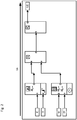
- Fig. 1 shows an example of a graphic representation of a signal processing functionality using a plurality of function modules 2.1, 2.2, 2.3 and 2.4 based on a predetermined format, each with at least one signal input and one signal output for specifying the respective functionalities or signal processing partial functionalities.
- this predetermined format is referred to below in the description and in the claims as the second format.
- connection modules 2.5, 2.6, 2.7 and 2.8 shown which represent the functionality of the respective physical interfaces coupled to the input side of the signal processing functionality, as well as the connection module 2.9, which represents a physical interface coupled to the output side of the signal processing functionality in terms of functionality, nowadays using for This second format equally determined engineering tools for creating an application program and subsequent configuration, including a parameterization associated therewith, and often also the commissioning of automation systems, ie used by at least one control device. That like in Fig.
- the image shown of a graphical representation of the signal processing functionality thus exemplarily represents a signal processing functionality to be implemented for a predetermined application by means of the appropriately provided and / or selected function modules and expediently further modules, which is originally functionally graphically represented on a graphical user interface, i.e. ultimately the application program to be processed after configuration.
- Such engineering tools for the configuration of a control device which are set up using and integrating a graphical user interface, functionally the signal processing functionality to be implemented for a respective application, i.e. ultimately the application program to be processed after generation and configuration, on a graphical user interface, i.e.
- function blocks based on the second format can consequently be used in the configuration of a control device by means of a configuration program that can process the function blocks based on this second format and can be executed on a data processing system and is set up for this purpose on one with the data processing system connected display device to represent a graphical user interface on which a plurality of function modules based on this second format are provided and can be used by means of the graphical user interface up to the configuration of the control device, so that one as exemplified in Fig. 1
- the graphical representation of the signal processing functionality shown can be displayed on the graphical user interface by means of the engineering tool that is therefore suitable for this and can be converted into an executable application program.
- Such a graphical representation of the signal processing functionality reproduced on the graphical user interface is then output as an image, e.g. printed out, by means of the engineering tool, this is also referred to as a so-called project printout within the scope of the invention.
- Such an image of a graphic representation or such a project printout can also be available as a PDF document, for example.
- FIG. 1 The image shown of a graphic representation of a signal processing functionality with a plurality of at least function blocks, all of which are based on the second format, in which case in the example shown, connection blocks based on the same format on the input and output sides are expediently coupled in a graphic representation, the method according to the invention including the preferred is below , described embodiments lying within the scope of the invention, ie to implement this image of a graphical representation of the signal processing functionality in a graphical representation of the signal processing functionality on a graphical user interface with, however, a plurality of at least function blocks that are based on another, predetermined format and can accordingly be used in the configuration of a control device by means of a configuration program that can process the function modules based on this other, predetermined format.
- this other predetermined format is referred to below in the description and in the claims as the first format.
- the function modules based on this other, predetermined, ie the first format and expediently further modules can consequently be used in the configuration of a control device by means of a configuration program which can be executed on a data processing system and is set up to display this on a display device connected to a data processing system to represent graphical user interface on which a plurality of function modules based on this first format are provided and can be used by means of the graphical user interface for the generation of an executable application program and the configuration of the control device based thereon.
- This graphical user interface provides a plurality of at least function modules which are based on the first format and each have at least one input for input signals and one output for output signals for specifying the respective signal processing sub-functionalities, and enables the function modules to be selected using the graphical user interface in order to to use them for the configuration of a hardware component, for example.
- the preferably safe modules and their functionalities are integrated, for example, into the graphic programming interface of the configuration software in order to implement a specific safety function in the creation of a safety logic, ie when a control device is configured.
- the function blocks provided and / or selected by means of the graphical user interface and, expediently, further blocks each have, for example, an equivalent in the hardware component on which a control logic is present, which includes the corresponding function blocks.
- the function blocks provided and also other blocks can be combined, for example, in a library or a respective memory area of one or more libraries.
- the corresponding function block can be selected, for example, using the graphical user interface, or it can also be provided that activation takes place after selection.
- a selected or activated function block can be used by means of the graphical user interface for parameterization and / or linking with other function blocks, so that the behavior of the function block (s) in the hardware component can be influenced.
- the function modules each provide a specific, independent function which act on input signals in order to generate output signals, with the function modules expediently each being able to be executed or activated independently.
- an image of a graphic representation of a signal processing functionality with at least a plurality of function modules based on the second format is first provided, for example the one in Fig.
- the function module 2.1 represents, for example, an emergency stop or emergency stop functionality, which can be assigned a parameterization property, for example a threshold value to be exceeded.
- the connection modules connected on the input side are graphically represented in accordance with the second format and are marked with 2.5 and 2.6 and indicate that according to Fig. 1 accordingly an input signal I0 is to be applied to the upper input and an input signal I1 to the lower input of function block 2.1.
- the output of function block 2.1 is in accordance with Fig. 1 for example applied to a first input of the function block 2.3, the function block 2.3 in the present example representing an AND link functionality.
- the output of function block 2.2 is applied to the second input of function block 2.3, which in turn provides two inputs to which a signal I2 assigned the reference symbol 2.7 and a signal I3 assigned the reference symbol 2.8 are to be applied.
- the output of the function block 2.3 is in turn applied to the input of a subsequent function block 2.4 which, in the present example, provides the signal processing sub-functionality of a special transistor circuit, for example.
- An output of the function module 2.4 is then connected, for example, to the connection module 2.9, at which, in the present case, an output signal O0 can be provided at the end of the graphically represented signal processing sub-functionality and can consequently be used further.
- such an image of a graphic representation or a project printout as mentioned above which is provided, for example, on paper or as a PDF file or also as an image file, such as a JPG file, is initially provided optically for subsequent image recognition scanned in, ie optically scanned, specifically along at least two different scanning directions, in particular in order to minimize scanning errors as far as possible for safety reasons and / or expediently detect possible sources of error as early as possible.
- the applications for which generic signal processing functionalities are to be implemented are not only non-safe applications, but often and primarily also safe applications, i.e. applications that are functionally safe have to.
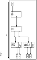
- Fig. 2 now greatly simplifies the optical scanning of the according to Fig. 1 provided image along a first scanning direction 3A, by way of example from the signal input side to the signal output side, in this respect, for illustration, also those in the image according to FIG Fig. 1 signal paths shown to illustrate the scanning direction Fig. 3 have been assigned an arrow corresponding to the scanning direction.
- Fig. 4 shows a further scanning process 3B, but in one for Fig. 2 scanning direction 3A shown in another, second scanning direction 3B, for example from the signal output side in the direction of the signal input side.
- the signal paths are in accordance with Fig. 1 for illustration at Fig. 4 likewise occupied by an arrow along this other scanning direction there.
- the Figures 3 and 5 show in a greatly simplified view a for processing a with the scanning along the first scanning direction ( Fig. 2 ) obtained image 2A subsequent, necessary process section or for processing a with the scanning along the second scanning direction ( Fig. 4 ) obtained image 2B following, necessary process section.
- the images 2A and 2B obtained with the scanning processes can also be imported into a data processing system immediately during scanning or after scanning for further processing, expediently into the one on which the configuration program, with which the modules based on the first format are configured during configuration a control device can be used, can be executed and is set up to display the graphical user interface on the display device connected to the data processing system.
- the further processing then comprises as a respective subsequent method section according to Fig. 3 performing an image recognition 4A of the image 2A obtained by the first scanning process, generating 5A based thereon of a first data set DS1 representing signal processing sub-functionalities and generating 6A a first intermediate code ZC1 based on the generated first data set DS1 and in a corresponding manner according to FIG Fig. 5 performing an image recognition 4B of the image 2B obtained by the second scanning process, generating 5B based thereon of a second data record DS2 representing signal processing sub-functionalities and generating 6B a second intermediate code ZC2 based on the generated second data record DS2.
- known graphic representations or symbols of function modules which are based on the second format and whose signal processing sub-functionalities are known to the configuration program and expediently also further modules are stored in a library or a memory area S.2 of such a library.
- the or more such libraries can thus be present on the data processing system on which the configuration program can be executed or on another external device and / or as program files, e.g. on a storage medium with a software program stored on it, which is stored on the data processing system can be executed and can be set up to interact with the configuration program that can be executed and set up on the data processing system to carry out the method, at least based on the images 2A, 2B obtained through the scanning processes.
- the respectively outlined procedural section is therefore given appropriate access to this or also to several such libraries for its implementation, in particular computer-assisted or software-assisted implementation.
- the configuration program itself or another appropriately set up program, for example, expediently the one on the aforementioned storage medium stored software program, in the context of each image recognition 4A, 4B, a comparison with the known graphic representations stored in the library S.2 of function modules based on the second format and known to the configuration program in their signal processing sub-functionalities, and expediently also other modules. If such a known graphic representation stored in the library S.2 is recognized, the signal processing sub-functionality known corresponding to this graphic representation is used for the generation 5A, 5B of the respective data set DS1, DS2 based on the image recognition.
- the signal processing sub-functionalities can therefore also be appropriately stored in the library or, for example, be determined in conjunction with the configuration program and therefore do not have to come directly from the library, which is entered into by the two Figures 3 and 5 is indicated by dashed arrows marked 5A and 5B, respectively. It is only essential, in particular, that the known graphic representations of function blocks based on the second format and expediently also other blocks stored in the library S.2 are unambiguous in their respective signal processing sub-functionality. Consequently, in a preferred development, the links between modules based on the second format contained in the images 2A, 2B obtained by the scanning processes are also evaluated during the detection and the generation of a respective data record DS1, DS2 based on this.
- a first or second intermediate code ZC1, ZC2, in particular a special machine code, is then generated based on the first data record DS1 and second data record DS2 generated in this way.
- step of comparing leads to the result that there is no identity of the first intermediate code ZC1 and the second intermediate code ZC2, an error message is expediently output and the method is ended. It can then be started again, for example by re-scanning the image twice.
- the configuration program is set up, in each case at least one function module 1.1., 1.2, 1.3 based on the first format for at least one known signal processing sub-functionality used in the generation automatically select, as with Fig. 7 on the user interface B sketched there with the reference numeral 8, and to graphically represent the signal processing functionality on the graphical user interface B, with recognized function blocks 2.1, 2.2, 2.3, 2.4 based on the second format and, expediently, also recognized other ones based on the second format Modules, i.e.
- connection modules 2.5, 2.6, 2.7, 2.8, 2.9 which represent physical interfaces in their function on the input side and output side of the signal processing functionality, through appropriately selected function modules 1.1., 1.2, 1.3 and, appropriately, also based on the first format by accordingly selected further modules based on the first format, that is to say in particular corresponding connection modules 1.5, 1.6, 1.7, 1.8, 1.9, 1.10, 1.11 are replaced.
- the function modules based on the first format and expediently also further modules are in this case, for example, again stored in a library or a memory area S.1 of such a library. Consequently, in the step of selecting 8, the links between modules based on the second format contained in the images 2A, 2B obtained by the scanning processes are preferably also evaluated again in order to ensure uniqueness in the selection.
- the configuration program consequently constructs the signal processing functionality entirely new based on the known signal processing sub-functionalities used, i.e. recognized signal processing sub-functionalities, using function modules based on the first format and expediently also further modules based on the first format. If all of the function blocks based on the second format and expediently also other blocks, i.e. in particular connection blocks, contained in Figures 2A and 2B were clearly identified, the result is the same signal processing functionality generated on the graphical user interface B, but also on the first Format instead of building blocks based on the second format.
- the signal processing functionality is graphically displayed on the graphical user interface B using the selected function blocks 1.1., 1.2, 1.3 based on the first format, their respective signal inputs and outputs are automatically linked to one another in accordance with the respective known signal processing sub-functionalities used during generation .
- At least the information as to which signal processing sub-functionalities have been recognized and, expediently, whether all have been recognized, are therefore available to the configuration program in the result or must be given to it by the program that carries out the recognition.
- the configuration program in the result or must be given to it by the program that carries out the recognition.
- a recognized function module based on the second format can be replaced by a single selected module based on the first format, such as function modules 2.3 and 2.4 (see also Fig. 1 ) through function block 1.3.
- a recognized function module based on the second format can of course also be replaced by several selected function modules based on the first format in the signal processing functionality graphically represented by the configuration program.
- the method and thus also the configuration program for such a case are set up in such a way that each unrecognized function module based on the second format or also further module is subsequently manipulated by means of the graphical user interface, in particular by at least one selected by a user the first format-based function block or other blocks can be replaced.
- the signal processing functionality finally generated using the configuration program and displayed on the graphical user interface and thus also the plurality of function modules based on the first format, each with at least one signal input and one signal output, can consequently also be used for the corresponding configuration of the control device.
- the signal processing functionality finally generated by means of the configuration program consequently also represents the application program to be created after such a program and then to be processed after configuration.
- an executable application program can consequently be generated and used for the configuration of the control device.
- the signal processing functionality graphically represented using the function modules based on the first format and possibly further modules is subjected to a plausibility check again by means of the configuration program. If the plausibility check also leads to a positive result, the configuration of the control device in the case of a safe application can again be viewed as safe.
Landscapes
- Engineering & Computer Science (AREA)
- Physics & Mathematics (AREA)
- General Physics & Mathematics (AREA)
- Automation & Control Theory (AREA)
- Software Systems (AREA)
- General Engineering & Computer Science (AREA)
- Theoretical Computer Science (AREA)
- Stored Programmes (AREA)
- Programmable Controllers (AREA)
- Processing Or Creating Images (AREA)
Description
Mit zunehmender Verbreitung und Komplexität von automatisierten Prozessen werden hierfür vorgesehenen Automatisierungssysteme sowohl für sichere (safe), als auch für nicht sichere (non-safe) Anwendungen mittels computergestützter Planung- und Projektierungswerkzeugen, sogenannter Engineeringtools, programmiert bzw. konfiguriert. Solche Engineeringtools ermöglichen in der Regel eine einfachere und übersichtlichere Erzeugung eines lauffähigen Anwendungsprogramms und anschließende Konfigurierung, einschließlich einer damit verbunden Parametrierung, und häufig auch Inbetriebnahme von Automatisierungssystemen. Dies erfolgt in der Regel unter Nutzung und Einbindung einer grafischen Benutzeroberfläche, so dass die Engineeringtools also eingerichtet sind, die für eine jeweilige Anwendung umzusetzende Signalverarbeitungsfunktionalität, d.h. letztlich das zu erzeugende und nach Konfiguration abzuarbeitende, lauffähige Anwendungsprogramm, auf einer grafischen Benutzeroberfläche funktionell, d.h. mittels bereitgestellten und/oder ausgewählten Funktionsbausteinen und weiteren Bausteinen grafisch darzustellen und zweckmäßig auch eine grafische Bedienbarkeit bereitzustellen. Die mit derartigen Engineeringtools programmierbaren bzw. konfigurierbaren Automatisierungssysteme umfassen folglich zumindest eine, speicherprogrammierbare Steuerungseinrichtung (SPS, englisch: Programmable Logic Controller, PLC), nachfolgend der Einfachheit halber als Steuerungseinrichtung bezeichnet.With the increasing spread and complexity of automated processes, automation systems intended for this purpose are programmed or configured for both safe and non-safe applications using computer-aided planning and configuration tools, so-called engineering tools. Such engineering tools generally enable a simpler and clearer generation of an executable application program and subsequent configuration, including associated parameterization, and often also the commissioning of automation systems. This is usually done using and integrating a graphical user interface, so that the engineering tools are set up to functionally, i.e. by means of, the signal processing functionality to be implemented for a respective application, i.e. ultimately the executable application program to be generated and processed after configuration, on a graphical user interface to graphically represent provided and / or selected function modules and further modules and expediently also to provide graphical operability. The automation systems that can be programmed or configured with such engineering tools consequently include at least one programmable logic controller (PLC), hereinafter referred to as a control device for the sake of simplicity.
Die grafische Darstellung einer Signalverarbeitungsfunktionalität umfasst in der Regel zweckmäßig auch weitere Bausteine, wie insbesondere Anschlussbausteine, welche jeweilige an die Eingangsseite und Ausgangsseite der Signalverarbeitungsfunktionalität gekoppelte physikalische Schnittstellen, wie beispielsweise elektrische Schraubklemmen in deren Funktionalität repräsentieren, an welchen die mittels der Signalverarbeitungsfunktionalität zu verarbeitenden Eingangssignale angelegt bzw. die Ausgangssignale am Ende der Signalverarbeitungsfunktionalität bereitgestellt und folglich weiterverwendet werden können.The graphic representation of a signal processing functionality usually also expediently includes further modules, such as connection modules in particular, which represent the respective physical interfaces coupled to the input side and output side of the signal processing functionality, such as electrical screw terminals in their functionality, to which the input signals to be processed by means of the signal processing functionality are applied or the output signals can be provided at the end of the signal processing functionality and consequently further used.
Den zur Programmierung und Konfiguration einsetzbaren Bausteinen sind hierbei jeweilige Funktionalitäten oder Teilfunktionalitäten, nachfolgend der Vereinheitlichung wegen auch als Signalverarbeitungsteilfunktionalitäten, welche auch Steuerungsfunktionalitäten enthalten können, bezeichnet, sowie spezifische grafische Symbole oder Darstellungen einander zugeordnet und in einer oder mehreren Bibliotheken bzw. dortigen Speicherbereichen abgelegt, auf welche das Engineeringtool zugreifen kann oder den Zugriff ermöglicht. Häufig können derartige Bausteine auch neu erschaffen und/oder verändert werden, z.B. auch durch Verknüpfung mehrerer Bausteine, und mit entsprechend neuen oder veränderten Funktionalitäten oder Teilfunktionalitäten sowie spezifischen grafischen Symbolen oder Darstellungen neu abgelegt werden.The modules that can be used for programming and configuration are in this case the respective functionalities or partial functionalities, hereinafter also referred to as signal processing partial functionalities, which can also contain control functionalities, for the sake of standardization, as well as specific graphic symbols or representations assigned to one another and stored in one or more libraries or memory areas there, which the engineering tool can access or enables access. Often such modules can also be newly created and / or changed, e.g. also by linking several modules, and stored anew with correspondingly new or changed functionalities or partial functionalities as well as specific graphic symbols or representations.
Die Auswahl und zweckmäßig auch weitere Bedienbarkeit eines Bausteins für das zu erstellende Anwendungsprogramm der zu konfigurierenden Steuereinrichtung erfolgt somit heutzutage in der Regel mittels einer grafischen Benutzeroberfläche. Je nach Anwendung kann hiermit auch der ausgewählte Baustein z.B. mit anderen Bausteinen verknüpft werden und/oder eine Belegung mit Ein- und/oder Ausgangssignalen durch entsprechende grafische Anbindung von Anschlussbausteinen an Funktionsbausteinen festgelegt werden.The selection and, expediently, also further operability of a module for the application program to be created for the control device to be configured is therefore usually nowadays carried out using a graphical user interface. Depending on the application, the selected module can also be linked with other modules, for example, and / or an assignment with input and / or output signals can be defined by corresponding graphical connection of connection modules to function modules.
In an und für sich bekannter Art und Weise kann die mittels der grafischen Benutzeroberfläche erzeugte grafische Darstellung einer Signalverarbeitungsfunktionalität bzw. eines zu erstellenden, nach Konfiguration abzuarbeitenden Anwendungsprogramms anschließend mittels der grafischen Benutzeroberfläche auch für die Konfiguration des Automatisierungssystems selbst, d.h. zumindest einer Steuereinrichtung herangezogen werden. Die Funktionsbausteine stellen somit jeweils eine bestimmte eigenständige Funktion bereit, die Eingangssignale auswerten, um Ausgangssignale zu erzeugen, wobei die Funktionsbausteine in der Regel mittels der grafischen Benutzeroberfläche jeweils eigenständig auswählbar, ausführbar und/oder aktivierbar sind.In a manner known per se, the graphical representation of a signal processing functionality or an application program to be created by means of the graphical user interface can then also be used by means of the graphical user interface for the configuration of the automation system itself, ie at least one control device. The function modules thus each provide a specific independent function that evaluate the input signals in order to generate output signals, the function modules usually being able to be selected, executed and / or activated independently by means of the graphical user interface.
Ein mittels der grafischen Benutzeroberfläche bereitgestellter und/oder ausgewählter Funktionsbaustein kann zum Beispiel auch einer Hardwarekomponente entsprechen, auf der eine Steuerungslogik vorhanden ist, welche den Funktionsbaustein bzw. dessen Teilfunktionalität bereitstellt.A function module provided and / or selected by means of the graphical user interface can, for example, also correspond to a hardware component on which control logic is present which provides the function module or its partial functionality.
Die für eine anwendungsbezogene Konfiguration ausgewählten bzw. zu verwendenden Funktionsbausteine bilden somit jeweils eine wesentliche Grundlage für eine bestimmte Signalverarbeitungsfunktionalität des zu erstellenden, lauffähigen Anwendungsprogramms einschl. der grafisch funktionellen Darstellung dieser Signalverarbeitungsfunktionalität bzw. des nach Konfiguration abzuarbeitenden Anwendungsprogramms und sind zweckmäßig auch zur Laufzeit des Anwendungsprogramms zur Statusanzeige und weiteren Konfiguration verwendbar.The function blocks selected or to be used for an application-related configuration thus each form an essential basis for a certain signal processing functionality of the executable application program to be created, including the graphical functional representation of this signal processing functionality or the application program to be processed after configuration, and are also useful when the application program is running can be used for status display and further configuration.
Ein Problem bei derartigen Engineeringtools ist hierbei, dass diese in der Regel einer Weiterentwicklung unterworfen sind und/oder unterschiedlichen Standards bzw. Formaten entsprechen und sich folglich auch die den jeweiligen Bausteinen innewohnenden Funktionalitäten ändern können oder anders sind, wie auch ergänzend oder alternativ die spezifischen grafischen Symbole oder Darstellungen von Bausteinen.A problem with such engineering tools is that they are usually subject to further development and / or correspond to different standards or formats and consequently the functionalities inherent in the respective modules can change or are different, as well as the specific graphic ones as a supplement or alternative Symbols or representations of building blocks.
Soll folglich eine einmal zusammengestellte Signalverarbeitungsfunktionalität von einem Entwicklungsstand auf einen anderen Entwicklungsstand umgesetzt werden, basierend auf welchem mit einem hierfür eingerichteten Engineeringtool auf einer grafischen Benutzeroberfläche grafisch dargestellte Funktionsbausteine und zweckmäßig weitere Bausteine mittels der grafischen Benutzeroberfläche für die Konfiguration einer Steuerungseinrichtung herangezogen werden können, wobei lediglich die grafische Darstellung der Signalverarbeitungsfunktionalität vorliegt, die es umzusetzen gilt in die grafische Darstellung derselben Signalverarbeitungsfunktionalität unter Verwendung von Funktionsbausteinen und zweckmäßig weiteren Bausteinen, welche dann auch wieder für die Konfiguration der Steuerungseinrichtung einsetzbar sind, ist dies in der Regel äußerst zeit- und kostenintensiv und in der Regel nur manuell durch entsprechende Kenntnis der gesamten, durch die grafische Darstellung repräsentierte, tatsächlich zu verwirklichende Signalverarbeitungsfunktionalität und also des nach Konfiguration abzuarbeitenden Anwendungsprogramms und/oder mittels Tryand-Error Versuche eines Anwenders möglich.If a signal processing functionality, once compiled, is to be converted from one development status to another development status, on the basis of which function modules graphically displayed on a graphical user interface with an engineering tool set up for this purpose and, expediently, further modules can be used for the configuration of a control device by means of the graphical user interface, with only If the graphical representation of the signal processing functionality is available, which needs to be implemented in the graphical representation of the same signal processing functionality using function blocks and other useful components, which can then also be used again for the configuration of the control device, this is usually extremely time-consuming and costly and in usually only manually through appropriate knowledge of the entire, represented by the graphic representation, actual I signal processing functionality to be realized and so of the application program to be processed after configuration and / or attempts by a user by means of try-and-error.
Ein Engineering-Tool zum Konfigurieren eines Automatisierungssystems ist zum Beispiel aus der Druckschrift
Eine Aufgabe der Erfindung besteht folglich darin, eine grafische Darstellung einer Signalverarbeitungsfunktionalität, die auf grafisch dargestellten Funktionsbausteinen und gegebenenfalls weiteren Bausteinen beruht, welche an und für sich für ein vorbestimmtes Engineering-Tool weder für die grafische Programmierung noch die Konfiguration von Automatisierungssystemen einsetzbar sind, automatisch in eine grafische Darstellung derselben Signalverarbeitungsfunktionalität umzusetzen, wobei diese grafische Darstellung auf grafisch dargestellten Funktionsbausteinen und gegebenenfalls weiteren Bausteinen basiert, welche in dem vorgenannten Engineering-Tool zur Erzeugung eines lauffähigen Anwendungsprogramms und entsprechenden Konfiguration von Automatisierungssystemen einsetzbar sind.One object of the invention is therefore to automatically create a graphic representation of a signal processing functionality that is based on graphically displayed function blocks and, if necessary, further blocks which in and of themselves cannot be used for a predetermined engineering tool either for graphic programming or the configuration of automation systems in a graphical representation of the same signal processing functionality, this graphical representation being based on graphically represented function blocks and possibly other blocks that can be used in the aforementioned engineering tool to generate an executable application program and corresponding configuration of automation systems.
Die Lösung der Aufgabe ist insbesondere durch ein Verfahren mit den Merkmalen nach Anspruch 1 dargestellt, wobei vorteilhafte und zweckmäßige Ausführungen Gegenstand der Unteransprüche sind.The object is achieved in particular by a method having the features according to claim 1, with advantageous and useful designs being the subject of the subclaims.
Die Erfindung schlägt folglich ein Verfahren zum Erzeugen einer grafischen Darstellung einer Signalverarbeitungsfunktionalität auf einer grafischen Benutzeroberfläche vor, und zwar unter Verwendung einer Mehrzahl von auf einem ersten Format basierenden Funktionsbausteinen mit jeweils zumindest einem Signaleingang und einem Signalausgang zur Vorgabe jeweiliger Signalverarbeitungsteilfunktionalitäten, und zwar basierend auf einer Mehrzahl von auf einem zweiten Format basierenden Funktionsbausteinen mit jeweils zumindest einem Signaleingang und einem Signalausgang zur Vorgabe jeweiliger Signalverarbeitungsteilfunktionalitäten, wobei die auf dem ersten Format basierenden Funktionsbausteine bei der Erzeugung eines lauffähigen Anwendungsprogramms und der Konfiguration einer Steuerungseinrichtung mittels eines Konfigurationsprogramms zum Einsatz kommen können und das Konfigurationsprogramm auf einer Datenverarbeitungsanlage ausführbar ist und dazu eingerichtet ist, auf einer mit der Datenverarbeitungsanlage verbundenen Anzeigeeinrichtung die grafische Benutzeroberfläche darzustellen, auf welcher eine Mehrzahl von auf diesem ersten Format basierenden Funktionsbausteinen bereitgestellt werden und mittels der grafischen Benutzeroberfläche für die Erstellung des Anwendungsprogramms und Konfiguration der Steuerungseinrichtung herangezogen werden können.The invention consequently proposes a method for generating a graphical representation of a signal processing functionality on a graphical user interface, specifically using a plurality of function modules based on a first format, each with at least one signal input and one signal output for specifying the respective signal processing sub-functionalities, based on a A plurality of function blocks based on a second format, each with at least one signal input and one signal output for specifying the respective signal processing sub-functionalities, whereby the function blocks based on the first format can be used to generate an executable application program and the configuration of a control device by means of a configuration program, and the configuration program can be executed on a data processing system and is set up for this purpose on a data processing system processing system connected display device the graphic To represent user interface on which a plurality of function modules based on this first format are provided and can be used by means of the graphical user interface for the creation of the application program and configuration of the control device.
Im Einzelnen sieht hierbei die Lösung nach der Erfindung vor, dass basierend auf einem optisch entlang einer ersten Einscannrichtung und entlang einer anderen, zweiten Einscannrichtung eingescannten, zuvor bereitgestellten Abbild einer grafischen Darstellung der Signalverarbeitungsfunktionalität mit einer Mehrzahl von auf dem zweiten Format basierenden Funktionsbausteinen, eine Bilderkennung des durch den ersten Einscannvorgang erhaltenen Bildes und ein hierauf basierendes Erzeugen eines ersten, Signalverarbeitungsteilfunktionalitäten repräsentierenden Datensatzes sowie eine Bilderkennung des durch den zweiten Einscannvorgang erhaltenen Bildes und hierauf basierendes Erzeugen eines zweiten, Signalverarbeitungsteilfunktionalitäten repräsentierenden Datensatzes durchgeführt wird.In detail, the solution according to the invention provides that, based on a previously provided image of a graphic representation of the signal processing functionality with a plurality of function modules based on the second format, an image recognition, which is optically scanned in along a first scanning direction and along another, second scanning direction of the image obtained by the first scanning process and a generation of a first data set representing signal processing sub-functionalities based thereon as well as image recognition of the image obtained by the second scanning process and based thereon generation of a second data set representing signal processing sub-functionalities.
Bei jeder dieser Bilderkennungen wird ein Vergleich mit in einer Bibliothek abgelegten bekannten grafischen Darstellungen bzw. Symbolen von auf dem zweiten Format basierenden und in deren Signalverarbeitungsteilfunktionalitäten dem Konfigurationsprogramm bekannten Funktionsbausteinen durchgeführt und bei jedem Erkennen einer solchen, in der Bibliothek abgelegten bekannten grafischen Darstellung, wird die entsprechend dieser grafischen Darstellung bekannte Signalverarbeitungsteilfunktionalität für die auf der Bilderkennung basierenden Erzeugung des jeweiligen Datensatzes herangezogen.
Basierend auf dem erzeugten ersten Datensatz wird anschließend ein erster Zwischencode und basierend auf dem erzeugten zweiten Datensatz ein zweiter Zwischencode generiert, welche daraufhin miteinander verglichen werden. Sofern der Schritt des Vergleichens zu dem Ergebnis einer Identität des ersten Zwischencodes und des zweiten Zwischencode führt, wird durch das Konfigurationsprogramm jeweils wenigstens ein auf dem ersten Format basierender Funktionsbaustein für jeweils wenigstens eine bei der Erzeugung herangezogene bekannte Signalverarbeitungsteilfunktionalität automatisch ausgewählt und die Signalverarbeitungsfunktionalität auf der grafischen Benutzeroberfläche grafisch dargestellt, wobei erkannte, auf dem zweiten Format basierende Funktionsbausteine durch ausgewählte, auf dem ersten Format basierende Funktionsbausteine ersetzt werden.With each of these image recognitions, a comparison is carried out with known graphic representations or symbols stored in a library of function blocks based on the second format and known to the configuration program in their signal processing sub-functionalities and each time such a known graphic representation stored in the library is recognized, the According to this graphical representation, known signal processing sub-functionality is used for the generation of the respective data record based on the image recognition.
Based on the generated first data set, a first intermediate code is then generated and based on the generated second data set, a second intermediate code is generated, which are then compared with one another. If the step of comparing leads to the result of an identity of the first intermediate code and the second intermediate code, the configuration program automatically selects at least one function module based on the first format for at least one known signal processing sub-functionality used in the generation and the Signal processing functionality shown graphically on the graphical user interface, with recognized function blocks based on the second format being replaced by selected function blocks based on the first format.
Insbesondere, wenn alle auf dem zweiten Format basierende Funktionsbausteine erkannt und durch ausgewählte, auf dem ersten Format basierende Funktionsbausteine ersetzt, kann folglich auch ein lauffähiges Anwendungsprogramm erzeugt und dieses für die Konfiguration der Steuerungseinrichtung herangezogen werden.In particular, if all function modules based on the second format are recognized and replaced by selected function modules based on the first format, an executable application program can consequently also be generated and used for the configuration of the control device.
Die Lösung der Aufgabe spiegelt sich auch in dem Speichermedium gemäß Anspruch 9 wieder, mit einem darauf gespeicherten Softwareprogramm, welches zur Umsetzung eben solcher grafischen Darstellungen, welche auf unterschiedlichen Funktionsbausteinen beruhen, geeignet ist.
Ein solches Softwareprogramm ist folglich zur Durchführung des erfindungsgemäßen Verfahrens auf der Datenverarbeitungsanlage ausführbar und dann zum Zusammenwirken mit dem auf der Datenverarbeitungsanlage ausführbaren und eingerichteten Konfigurationsprogramm zumindest basierend auf den durch die Einscannvorgänge erhaltenen Bildern eingerichtet.The solution to the problem is also reflected in the storage medium according to claim 9, with a software program stored thereon which is suitable for implementing such graphic representations which are based on different function modules.
Such a software program can consequently be executed on the data processing system to carry out the method according to the invention and is then set up to interact with the configuration program that can be executed and set up on the data processing system, at least based on the images obtained from the scanning processes.
Weitere Vorteile und Merkmale und/oder Ausführungsbeispiele der Erfindung werden bezugnehmend auf die nachfolgende Beschreibung anhand der beigefügten Zeichnungen offensichtlich. In den Zeichnungen zeigen:
-
Fig. 1 , stark vereinfacht ein Abbild einer grafischen Darstellung einer Signalverarbeitungsfunktionalität mit einer Mehrzahl von verknüpften, auf einem zweiten, d.h. umzusetzenden Format basierenden Funktionsbausteinen einschließlich daran angebundenen Anschlussbausteinen, -
Fig. 2 , stark vereinfacht eine Prinzipdarstellung eines optischen Einscannvorgangs, des inFig. 1 dargestellten Abbildes entlang einer ersten Einscannrichtung, -
Fig. 3 , stark vereinfacht eine schematische Ansicht eines nachfolgenden, zur Verarbeitung des mit dem Einscannen entlang der ersten Einscannrichtung erhaltenen Bildes notwendigen Verfahrensabschnitts, -
Fig. 4 , stark vereinfacht eine Prinzipskizze eines optischen Einscannvorgangs, der inFig. 1 dargestellten grafischen Darstellung entlang einer zur ersten Einscannrichtung anderen, zweiten Einscannrichtung, -
Fig. 5 , stark vereinfacht eine derFig. 3 entsprechende schematische Ansicht, jedoch zur Verarbeitung des mit dem Einscannen entlang der zweiten Einscannrichtung erhaltenen Bildes, -
Fig. 6 , stark vereinfacht eine Prinzipdarstellung eines Vergleichs der durch die beiden Verfahrensabschnitte gemäßFiguren 3 und5 erhaltenen Ergebnisse, -
Fig. 7 , stark vereinfacht eine schematische Ansicht eines in Abhängigkeit des gemäßFig. 6 gewonnenen Vergleichsergebnisses nachfolgenden Verfahrensabschnitts zum letztendlichen Erzeugen einer grafischen Darstellung der Signalverarbeitungsfunktionalität entsprechend des eingescannten Abbildes, jedoch auf einer grafischen Benutzeroberfläche, und zwar unter Verwendung einer Mehrzahl von auf dem ersten Format basierenden Funktionsbausteinen, d.h. allgemein gesprochen zur Umsetzung der für die grafische Darstellung einer Signalverarbeitungsfunktionalität herangezogenen Funktionsbausteine von einem für ein Engineeringtool zur Konfiguration nichteinsetzbaren Format bzw. entsprechenden Standard auf das für das Engineeringtool zur Konfiguration einsetzbare Format bzw. den entsprechenden Standard,
und -
Fig. 8 , stark vereinfacht eine schematische, beispielhafte grafische Darstellung der Signalverarbeitungsfunktionalität, bei einer nicht vollständig durchführbaren Umsetzung.
-
Fig. 1 , greatly simplified, an image of a graphic representation of a signal processing functionality with a plurality of linked function modules based on a second, ie format to be converted, including connection modules connected to them, -
Fig. 2 , greatly simplified a schematic representation of an optical scanning process, the inFig. 1 the image shown along a first scanning direction, -
Fig. 3 , greatly simplified, a schematic view of a subsequent process section necessary for processing the image obtained with the scanning along the first scanning direction, -
Fig. 4 , greatly simplified, a schematic diagram of an optical scanning process, which is shown inFig. 1 the graphical representation shown along a second scanning direction other than the first scanning direction, -
Fig. 5 , greatly simplified one of theFig. 3 Corresponding schematic view, however, for processing the image obtained by scanning along the second scanning direction, -
Fig. 6 , greatly simplified a basic illustration of a comparison of the two method sections according to FIGFigures 3 and5 results obtained, -
Fig. 7 , greatly simplified a schematic view of a depending on theFig. 6 obtained comparison result of the following procedural section to ultimately generate a graphical representation of the signal processing functionality according to the scanned image, but on a graphical user interface, using a plurality of function modules based on the first format, i.e. generally speaking for the implementation of the graphical representation of a signal processing functionality Function blocks from a format or a corresponding standard that cannot be used for an engineering tool for configuration to the format or the corresponding standard that can be used for the engineering tool for configuration,
and -
Fig. 8 , greatly simplified, a schematic, exemplary graphic representation of the signal processing functionality, in the case of an implementation that cannot be fully implemented.
Nachfolgend wird auf die Figuren Bezug genommen, anhand derer verschiedene Vorteile, Merkmale ersichtlich und bevorzugten Ausführungsbeispiele näher erläutert werden.In the following, reference is made to the figures, on the basis of which various advantages, features are evident and preferred exemplary embodiments are explained in more detail.
Für eine konsistente Begrifflichkeit wird dieses vorbestimmte Format nachfolgend in der Beschreibung sowie in den Ansprüchen als zweites Format bezeichnet.For consistent terminology, this predetermined format is referred to below in the description and in the claims as the second format.
Wie in der Beschreibungseinleitung beschrieben, können solche, auf dem zweiten Format basierende Funktionsbausteine und in der Regel auch weitere auf diesem zweiten Format basierende Bausteine, wie z.B. die in
Solche Engineeringtools zur Konfigurierung einer Steuereinrichtung, welche unter Nutzung und Einbindung einer grafischen Benutzeroberfläche eingerichtet sind, die für eine jeweilige Anwendung umzusetzende Signalverarbeitungsfunktionalität, d.h. letztlich das nach Erzeugung und Konfiguration abzuarbeitende Anwendungsprogramm, auf einer grafischen Benutzeroberfläche funktionell, d.h. mittels bereitgestellten und/oder ausgewählten, auf einem vorbestimmten Format basierenden Funktionsbausteinen und weiteren Bausteinen grafisch darzustellen und somit zweckmäßig auch eine grafische Bedienbarkeit bereitzustellen, umfassen somit zumindest ein Konfigurationsprogramm, welches auf einer Datenverarbeitungsanlage ausführbar ist und dazu eingerichtet ist, auf einer mit der Datenverarbeitungsanlage verbundenen Anzeigeeinrichtung eine grafische Benutzeroberfläche darzustellen, auf welcher eine Mehrzahl von auf diesem bestimmten Format basierenden Funktionsbausteinen und weiteren Bausteinen bereitgestellt werden und mittels der grafischen Benutzeroberfläche für die Konfiguration der Steuerungseinrichtung herangezogen werden können.Such engineering tools for the configuration of a control device, which are set up using and integrating a graphical user interface, functionally the signal processing functionality to be implemented for a respective application, i.e. ultimately the application program to be processed after generation and configuration, on a graphical user interface, i.e. by means of provided and / or selected, To graphically represent function modules and other modules based on a predetermined format and thus expediently also to provide graphical operability, thus comprise at least one configuration program which can be executed on a data processing system and is set up to display a graphical user interface on a display device connected to the data processing system which provides a plurality of function modules based on this specific format and further modules llt and can be used by means of the graphical user interface for the configuration of the control device.
Mit anderen Worten können also z.B. auf dem zweiten Format basierende Funktionsbausteine folglich bei der Konfiguration einer Steuerungseinrichtung mittels eines Konfigurationsprogramms zum Einsatz kommen, das die auf diesem zweiten Format basierende Funktionsbausteine verarbeiten kann und auf einer Datenverarbeitungsanlage ausführbar und dazu eingerichtet ist, auf einer mit der Datenverarbeitungsanlage verbundenen Anzeigeeinrichtung eine grafische Benutzeroberfläche darzustellen, auf welcher eine Mehrzahl von auf diesem zweiten Format basierenden Funktionsbausteinen bereitgestellt werden und mittels der grafischen Benutzeroberfläche bis hin zur Konfiguration der Steuereinrichtung herangezogen werden können, so dass eine wie beispielhaft in
Alle die auf dem zweiten Format basierenden mittels dem somit dazu geeigneten Engineeringtool auf der grafischen Benutzeroberfläche grafisch dargestellten Funktionsbausteine, zweckmäßig auch weiteren Bausteine, insbesondere Anschlussbausteine, repräsentieren also in deren Gesamtheit für das dafür geeignete Engineeringtools und grafisch dargestellt die darin enthaltene Signalverarbeitungsfunktionalität bzw. das nach Wandelung in ein ausführbares und nach entsprechender Konfiguration abzuarbeitende Anwendungsprogramm und also insbesondere die damit repräsentierte
- Programmlogik, insbesondere als Programmcode und/oder grafische Logik,
- die HW-Konfiguration für den HW-Aufbau (HW=Hardware), einschließlich eventueller Bustopologien,
- die HW-Parametrierung, wie beispielsweise Testtakte und Filterzeiten,
- die Parameter von Funktionsbausteinen und/oder etwaige Kommentare, Betriebsmittelkennzeichen, I/O-Listen (Input/Output-Listen) etc..
- Program logic, in particular as program code and / or graphic logic,
- the HW configuration for the HW structure (HW = hardware), including any bus topologies,
- the HW parameterization, such as test cycles and filter times,
- the parameters of function blocks and / or any comments, device tags, I / O lists (input / output lists) etc.
Wird eine solche auf der grafischen Benutzeroberfläche wiedergegebene grafische Darstellung der Signalverarbeitungsfunkionalität mittels des Engineeringtools anschließend als Abbild ausgegeben, z.B. ausgedruckt, wird hierbei im Rahmen der Erfindung auch von einem sogenannten Projektausdruck gesprochen. Ein solches Abbild einer grafischen Darstellung bzw. ein solcher Projektausdruck kann z.B. auch als PDF-Dokument vorliegen.If such a graphical representation of the signal processing functionality reproduced on the graphical user interface is then output as an image, e.g. printed out, by means of the engineering tool, this is also referred to as a so-called project printout within the scope of the invention. Such an image of a graphic representation or such a project printout can also be available as a PDF document, for example.
Anhand eines solchen, wie bei
Für eine konsistente Begrifflichkeit wird dieses andere vorbestimmte Format nachfolgend in Beschreibung sowie in den Ansprüchen als erstes Format bezeichnet.For consistent terminology, this other predetermined format is referred to below in the description and in the claims as the first format.
Die auf diesem anderen, vorbestimmten, d.h. dem ersten Format basierenden Funktionsbausteine und zweckmäßig weiteren Bausteine können folglich bei der Konfiguration einer Steuerungseinrichtung mittels eines Konfigurationsprogramms zum Einsatz kommen, welches auf einer Datenverarbeitungsanlage ausführbar ist und dazu eingerichtet ist, auf einer mit einer Datenverarbeitungsanlage verbundenen Anzeigeeinrichtung diese grafische Benutzeroberfläche darzustellen, auf welcher eine Mehrzahl von auf diesem ersten Format basierenden Funktionsbausteinen bereitgestellt werden und mittels der grafischen Benutzeroberfläche für die Erzeugung eines lauffähigen Anwendungsprogramms und der hierauf basierten Konfiguration der Steuerungseinrichtung herangezogen können.The function modules based on this other, predetermined, ie the first format and expediently further modules can consequently be used in the configuration of a control device by means of a configuration program which can be executed on a data processing system and is set up to display this on a display device connected to a data processing system to represent graphical user interface on which a plurality of function modules based on this first format are provided and can be used by means of the graphical user interface for the generation of an executable application program and the configuration of the control device based thereon.
Diese grafische Benutzeroberfläche stellt dabei eine Mehrzahl zumindest von Funktionsbausteinen, welche auf dem ersten Format basieren und jeweils zumindest einen Eingang für Eingangssignale und einen Ausgang für Ausgangssignale zur Vorgabe jeweiliger Signalverarbeitungsteilfunktionalitäten besitzen, bereit und ermöglicht es, die Funktionsbausteine jeweils mittels der grafischen Benutzeroberfläche auszuwählen, um sie für die Konfiguration z.B. einer Hardwarekomponente heranzuziehen. Dazu sind die bevorzugt sicheren Bausteine und deren Funktionalitäten z.B. in die grafische Programmieroberfläche der Konfigurationssoftware integriert, um in der Erstellung einer Sicherheitslogik, d.h. bei der Konfiguration einer Steuerungseinrichtung eine spezifische Sicherheitsfunktion zu realisieren. Die mittels der grafischen Benutzeroberfläche bereitgestellten und/oder ausgewählten Funktionsbausteine und zweckmäßig auch weiteren Bausteine haben z.B. jeweils eine Entsprechung in der Hardwarekomponente, auf der eine Steuerungslogik vorhanden ist, welche die entsprechenden Funktionsbausteine umfasst. Die bereitgestellten Funktionsbausteine und auch weiteren Bausteine können z.B. in einer Bibliothek oder einem jeweiligen Speicherbereich einer oder mehrerer Bibliotheken zusammengefasst sein. Um einen Funktionsbaustein zu aktivieren bzw. in die Steuerungslogik und/oder Signalverarbeitungsfunkionalität einzubeziehen, kann der entsprechende Funktionsbaustein z.B. mittels der grafischen Benutzeroberfläche ausgewählt werden, oder es kann ggf. auch vorgesehen sein, dass die Aktivierung nach dem Auswählen erfolgt. Insbesondere kann ein ausgewählter bzw. aktivierter Funktionsbaustein mittels der grafischen Benutzeroberfläche zur Parametrierung und/oder Verknüpfung mit anderen Funktionsbausteinen genutzt werden, so dass das Verhalten des oder der Funktionsbausteine in der Hardwarekomponente beeinflusst werden kann. Die Funktionsbausteine stellen jeweils eine bestimmte, eigenständige Funktion bereit, die auf Eingangssignale einwirken, um Ausgangssignale zu erzeugen, wobei die Funktionsbausteine zweckmäßig jeweils eigenständig ausführbar bzw. aktivierbar sind.This graphical user interface provides a plurality of at least function modules which are based on the first format and each have at least one input for input signals and one output for output signals for specifying the respective signal processing sub-functionalities, and enables the function modules to be selected using the graphical user interface in order to to use them for the configuration of a hardware component, for example. For this purpose, the preferably safe modules and their functionalities are integrated, for example, into the graphic programming interface of the configuration software in order to implement a specific safety function in the creation of a safety logic, ie when a control device is configured. The function blocks provided and / or selected by means of the graphical user interface and, expediently, further blocks each have, for example, an equivalent in the hardware component on which a control logic is present, which includes the corresponding function blocks. The function blocks provided and also other blocks can be combined, for example, in a library or a respective memory area of one or more libraries. To activate a function block or to include it in the control logic and / or signal processing functionality, the corresponding function block can be selected, for example, using the graphical user interface, or it can also be provided that activation takes place after selection. In particular, a selected or activated function block can be used by means of the graphical user interface for parameterization and / or linking with other function blocks, so that the behavior of the function block (s) in the hardware component can be influenced. The function modules each provide a specific, independent function which act on input signals in order to generate output signals, with the function modules expediently each being able to be executed or activated independently.
Zur entsprechenden Umsetzung einer grafischen Darstellung einer Signalverarbeitungsfunktionalität mit zumindest einer Mehrzahl von auf dem zweiten Format basierenden Funktionsbausteinen in eine grafische Darstellung einer Signalverarbeitungsfunktionalität unter Verwendung einer Mehrzahl von auf dem ersten Format basierenden Funktionsbausteinen mit jeweils zumindest einem Signaleingang und einem Signalausgang zur Vorgabe jeweiliger Signalverarbeitungsteilfunktionalitäten, d.h. insbesondere zur Erzeugung einer solchen umgesetzten grafischen Darstellung einer Signalverarbeitungsfunktionalität auf einer grafischen Benutzeroberfläche, wird zunächst ein Abbild einer grafischen Darstellung einer Signalverarbeitungsfunktionalität mit zumindest einer Mehrzahl von auf dem zweiten Format basierenden Funktionsbausteinen bereitgestellt, z.B. das in
Der Funktionsbaustein 2.1 repräsentiert hierbei als Signalverarbeitungsteilfunktionalität beispielsweise eine Notaus- bzw. Nothalt-Funktionalität, welche mit einer Parametrierungseigenschaft, beispielsweise einem zu überschreitendem Schwellwert belegt sein kann. Die entsprechend dem zweiten Format grafisch dargestellten, eingangsseitig angebundenen Anschlussbausteine sind mit 2.5 und 2.6 gekennzeichnet und zeigen an, dass gemäß
Gemäß der Erfindung wird ein solches Abbild einer grafischen Darstellung bzw. ein wie vorstehend erwähnter Projektausdruck, welcher z.B. ausgedruckt auf Papier oder als PDF-Datei oder auch als Bild-Datei, wie z.B. als JPG-Datei bereitgestellt wird, zunächst optisch für eine nachfolgende Bilderkennung eingescannt, d.h. optisch abgetastet, und zwar entlang wenigstens zwei unterschiedlichen Einscannrichtungen, insbesondere, um aus Sicherheitsgründen Einscannfehler soweit als möglich zu minimieren und/oder mögliche Fehlerquellen zweckmäßigerweise so früh als möglich zu detektieren. Wie eingangs beschrieben, handelt es sich bei den Anwendungen, für welche gattungsbildende Signalverarbeitungsfunktionalitäten umzusetzen sind, nicht nur um nicht sichere (non-safe) Anwendungen, sondern häufig und vorrangig auch um sichere (safe) Anwendungen, d.h. Anwendungen, die in deren Funktion sicher sein müssen.According to the invention, such an image of a graphic representation or a project printout as mentioned above, which is provided, for example, on paper or as a PDF file or also as an image file, such as a JPG file, is initially provided optically for subsequent image recognition scanned in, ie optically scanned, specifically along at least two different scanning directions, in particular in order to minimize scanning errors as far as possible for safety reasons and / or expediently detect possible sources of error as early as possible. How As described at the beginning, the applications for which generic signal processing functionalities are to be implemented are not only non-safe applications, but often and primarily also safe applications, i.e. applications that are functionally safe have to.
Die
Die mit den Einscannvorgänge erhaltenen Bilder 2A und 2B können hierzu ferner unmittelbar beim Einscannen oder im Anschluss an das Einscannen zur weiteren Verarbeitung in eine Datenverarbeitungslage importiert, zweckmäßig in die, auf welcher das Konfigurationsprogramms, mit welchem die auf dem ersten Format basierenden Bausteine bei der Konfiguration einer Steuerungseinrichtung zum Einsatz kommen können, ausführbar und dazu eingerichtet ist, auf der mit der Datenverarbeitungsanlage verbundenen Anzeigeeinrichtung die grafische Benutzeroberfläche darzustellen.The
Die weitere Verarbeitung umfasst als jeweils nachfolgenden Verfahrensabschnitt dann gemäß
Hierzu sind in einer Bibliothek, oder einem Speicherbereich S.2 einer solchen Bibliothek bekannte grafische Darstellungen bzw. Symbole von auf dem zweiten Format basierenden und in deren Signalverarbeitungsteilfunktionalitäten dem Konfigurationsprogramm bekannte Funktionsbausteinen und zweckmäßig auch weiteren Bausteinen hinterlegt. Die oder auch mehrere solcher Bibliotheken kann bzw. können somit auf der Datenverarbeitungslage, auf welcher das Konfigurationsprogramm ausführbar sein oder auch auf einer weiteren externen Einrichtung sein und/oder als Programmdateien vorliegen, z.B. auf einem Speichermedium mit einem darauf gespeicherten Softwareprogramm, welches auf der Datenverarbeitungsanlage ausführbar und zum Zusammenwirken mit dem auf der Datenverarbeitungsanlage ausführbaren und eingerichteten Konfigurationsprogramm zur Durchführung des Verfahrens zumindest basierend auf den durch die Einscannvorgänge erhaltenen Bildern 2A, 2B einrichtbar ist. Zumindest während des in den
Folglich führt das Konfigurationsprogramm selbst oder ein anderes entsprechend eingerichtetes Programm, z.B. zweckmäßig das auf dem vorgenannten Speichermedium gespeicherte Softwareprogramm, im Rahmen jeder Bilderkennung 4A, 4B einen Vergleich mit in den in der Bibliothek S.2 abgelegten bekannten grafischen Darstellungen von auf dem zweiten Format basierenden und in deren Signalverarbeitungsteilfunktionalitäten dem Konfigurationsprogramm bekannten Funktionsbausteinen und zweckmäßig auch weiteren Bausteinen durch. Wird eine solche, in der Bibliothek S.2 abgelegte bekannte grafische Darstellung erkannt, wird die entsprechend dieser grafischen Darstellung bekannte Signalverarbeitungsteilfunktionalität für die auf der Bilderkennung basierenden Erzeugung 5A, 5B des jeweiligen Datensatzes DS1, DS2 herangezogen. Auch die Signalverarbeitungsteilfunktionalitäten können folglich zweckmäßig mit in der Bibliothek hinterlegt sein oder z.B. in Zusammenwirken mit dem Konfigurationsprogramm ermittelt werden und müssen also nicht unmittelbar aus der Bibliothek stammen, welches durch die beiden in den
Basierend auf dem so erzeugten ersten Datensatz DS1 und zweiten Datensatz DS2 wird dann jeweils ein erster bzw. zweiter Zwischencode ZC1, ZC2, insbesondere spezieller Maschinencode generiert.A first or second intermediate code ZC1, ZC2, in particular a special machine code, is then generated based on the first data record DS1 and second data record DS2 generated in this way.
Die bei vorstehend beschriebenen Verfahrensabschnitten erhaltenen Ergebnisse, d.h. die gemäß
Die in den eingescannten Bildern 2A und 2B enthaltenen Informationen, insbesondere auch die darin enthaltene Signalverarbeitungsfunktionalität, zunächst durch die vorbeschriebene Erkennung und nachfolgende Datensatzerzeugung auszuwerten und anschließend, d.h. vor einem Vergleich, nochmals diese erzeugten Datensätze in einen jeweiligen Zwischencode zu wandeln und folglich erst diese Zwischencodes ZC1 und ZC2 miteinander zu vergleichen, bietet als einen wesentlichen Vorteil, dass ein solcher Vergleich bereits an und für sich auf Programmebene erfolgt und nicht lediglich allein auf optischer Grafikerkennung und/oder optisch identifizierten Baustein einschließlich der grafisch dargestellten (Teil-)Funktionalität. Mit anderen Worten müssen bereits zwei vom Grundsatz her für einen Prozessor ausführbare Codes für einen Identitätsvergleich vorliegen.The information contained in the scanned
Sofern der Schritt des Vergleichens (vgl.
Sofern der Schritt des Vergleichens (vgl.
Das Konfigurationsprogramm konstruiert folglich basierend auf den herangezogenen bekannten Signalverarbeitungsteilfunktionalitäten, d.h. also erkannten Signalverarbeitungsteilfunktionalitäten, unter Verwendung von auf dem ersten Format basierenden Funktionsbausteinen und zweckmäßig auch von auf dem ersten Format basierenden weiteren Bausteinen, die Signalverarbeitungsfunktionalität insgesamt neu. Wurden alle in den Bildern 2A und 2B enthaltenen, auf dem zweiten Format basierenden Funktionsbausteine und zweckmäßig auch weiteren Bausteine, also insbesondere Anschlussbausteine eindeutig erkannt, ergibt sich folglich die in der Funktionalität selbe, auf der grafischen Benutzeroberfläche B erzeugte Signalverarbeitungsfunktionalität, jedoch mit auf dem ersten Format anstelle von mit auf dem zweiten Format basierenden Bausteinen. Zweckmäßig werden demnach beim grafischen Darstellen der Signalverarbeitungsfunktionalität auf der grafischen Benutzeroberfläche B unter Verwendung der ausgewählten, auf dem ersten Format basierenden Funktionsbausteinen 1.1., 1.2, 1.3 auch deren jeweilige Signaleingänge und Signalausgänge entsprechend der jeweiligen, bei der Erzeugung herangezogenen bekannten Signalverarbeitungsteilfunktionalitäten automatisch mit einander verknüpft.The configuration program consequently constructs the signal processing functionality entirely new based on the known signal processing sub-functionalities used, i.e. recognized signal processing sub-functionalities, using function modules based on the first format and expediently also further modules based on the first format. If all of the function blocks based on the second format and expediently also other blocks, i.e. in particular connection blocks, contained in Figures 2A and 2B were clearly identified, the result is the same signal processing functionality generated on the graphical user interface B, but also on the first Format instead of building blocks based on the second format. Accordingly, when the signal processing functionality is graphically displayed on the graphical user interface B using the selected function blocks 1.1., 1.2, 1.3 based on the first format, their respective signal inputs and outputs are automatically linked to one another in accordance with the respective known signal processing sub-functionalities used during generation .
Zumindest die Information, welche Signalverarbeitungsteilfunktionalitäten erkannt worden und zweckmäßig, ob alle erkannt worden sind, liegen dem Konfigurationsprogramm somit im Ergebnis vor bzw. müssen diesem vom Programm, welches die Erkennung durchführt an die Hand gegeben werden. In bevorzugter Ausführung, wie auf der gemäß
Wie bei
Insbesondere, für den Anwendungsfall, wenn die mit den Einscannvorgängen erhaltenen Bilder 2A und 2B, zumindest die hierin enthaltenen, auf dem zweiten Format basierenden Funktionsbausteine und zweckmäßig auch weiteren Bausteine dem Konfigurationsprogramm zur Verfügung gestellt werden, ist ferner im Rahmen der Erfindung vorgesehen, dass, wenn nicht alle auf dem zweiten Format basierenden Funktionsbausteine oder weiteren Bausteine bei der Bilderkennung durch Vergleich mit den in der Bibliothek S.2 abgelegten bekannten grafischen Darstellungen erkannt worden sind, ein solcher, auf dem zweiten Format basierender, nicht erkannter Funktionsbaustein oder weiterer Baustein bei der grafischen Darstellung der Signalverarbeitungsfunktionalität durch das Konfigurationsprogramm, mittels welchem erkannte, auf dem zweiten Format basierende Funktionsbausteine durch ausgewählte, auf dem ersten Format basierende Funktionsbausteine ersetzt werden, weiterhin dargestellt wird. Ein solches Beispiel ist in
Besonders bevorzugt ist das Verfahren und also auch das Konfigurationsprogramm für einen solchen Fall dahingehend eingerichtet, dass jeder auf dem zweiten Format basierende, nicht erkannte Funktionsbaustein oder auch weitere Baustein mittels der grafischen Benutzeroberfläche nachträglich manipuliert, insbesondere durch wenigstens einen, von einem Benutzer ausgewählten, auf dem ersten Format basierenden Funktionsbaustein oder auch weiteren Baustein ersetzt werden kann.Particularly preferably, the method and thus also the configuration program for such a case are set up in such a way that each unrecognized function module based on the second format or also further module is subsequently manipulated by means of the graphical user interface, in particular by at least one selected by a user the first format-based function block or other blocks can be replaced.
Die unter Verwendung des Konfigurationsprogramms abschließend erzeugte, auf grafischen Benutzeroberfläche dargestellte Signalverarbeitungsfunktionalität und also auch die hierfür verwendete Mehrzahl von auf dem ersten Format basierenden Funktionsbausteinen mit jeweils zumindest einem Signaleingang und einem Signalausgang können folglich auch für die entsprechende Konfiguration der Steuerungseinrichtung herangezogen werden können. Entsprechendes gilt selbstverständlich für alle auf dem ersten Format basierenden weiteren Bausteine, welche gegebenenfalls beim Erzeugen der grafischen Darstellung dieser Signalverarbeitungsfunktionalität verwendet wurden. Die mittels des Konfigurationsprogramm abschließend erzeugte Signalverarbeitungsfunktionalität repräsentiert folglich auch das nach einer solchen zu erstellende und nach Konfiguration dann abzuarbeitende Anwendungsprogramm.The signal processing functionality finally generated using the configuration program and displayed on the graphical user interface and thus also the plurality of function modules based on the first format, each with at least one signal input and one signal output, can consequently also be used for the corresponding configuration of the control device. The same applies, of course, to all further modules based on the first format that may have been used when generating the graphical representation of this signal processing functionality. The signal processing functionality finally generated by means of the configuration program consequently also represents the application program to be created after such a program and then to be processed after configuration.
Mit anderen Worten, sind alle auf dem zweiten Format basierende Funktionsbausteine erkannt und durch ausgewählte, auf dem ersten Format basierende Funktionsbausteine ersetzt, oder nichterkannte entsprechend manipuliert, kann folglich ein lauffähiges Anwendungsprogramm erzeugt und dieses für die Konfiguration der Steuerungseinrichtung herangezogen werden.In other words, if all function blocks based on the second format are recognized and replaced by selected function blocks based on the first format, or if not recognized function blocks are appropriately manipulated, an executable application program can consequently be generated and used for the configuration of the control device.
Vorzugsweise wird jedoch, wenn alle auf dem zweiten Format basierenden Bausteine erkannt und ersetzt oder gegebenenfalls nachträglich auch manipuliert worden sind, die unter Verwendung der auf dem ersten Format basierenden Funktionsbausteine und gegebenenfalls weiteren Bausteinen grafisch dargestellte Signalverarbeitungsfunktionalität nochmals mittels des Konfigurationsprogrammes einer Plausibilitätsprüfung unterzogen. Führt auch die Plausibilitätsprüfung zu einem positiven Ergebnis, kann folglich auch die Konfiguration der Steuerungseinrichtung im Falle einer sicheren (safe) Anwendung wiederum als sicher (safe) angesehen werden.Preferably, however, when all modules based on the second format have been recognized and replaced or possibly also subsequently manipulated, the signal processing functionality graphically represented using the function modules based on the first format and possibly further modules is subjected to a plausibility check again by means of the configuration program. If the plausibility check also leads to a positive result, the configuration of the control device in the case of a safe application can again be viewed as safe.
Claims (9)
- A method for generating a graphical representation of a signal processing functionality on a graphical user interface (B) using a plurality of functional blocks (1.1., 1.2, 1.3) that are based on a first format, each having at least one signal input and one signal output, for specifying respective signal processing sub-functionalities based on a plurality of functional blocks (2.1, 2.2, 2.3, 2,4) that are based on a second format, each having at least one signal input and one signal output, for specifying respective signal processing sub-functionalities;
wherein the functional blocks that are based on the first format can be used when configuring a controller using a configuration program, and wherein the configuration program can be executed on a data processing system and is configured to display, on a display device connected to the data processing system, said graphical user interface (B) which provides a plurality of functional blocks based on said first format, which can be used for the configuration of the controller using the graphical user interface, comprising the steps of:providing an image of a graphical representation of the signal processing functionality with a plurality of functional blocks (2.1, 2.2, 2.3, 2.4) that are based on the second format;- optically scanning (3A, 3B) said image, with a first optical scanning process (3A) performed along a first scanning direction and a second optical scanning process (3B) performed along a second scanning direction that is different from the first scanning direction;- performing an image recognition (4A) of the image (2A) obtained by the first scanning process and, based thereon, generating (5A) a first data set (DS1) representing signal processing sub-functionalities, and performing an image recognition (4B) of the image (2B) obtained by the second scanning process and, based thereon, generating (5B) a second data set (DS2) representing signal processing sub-functionalities, wherein each image recognition (4A, 4B) includes the performing of a comparison with known graphical representations of functional blocks that are based on the second format and are known to the configuration program in terms of their signal processing sub-functionalities and which are stored in a library (S.2), and wherein in each event of identifying such a known graphical representation stored in the library (S.2), the known signal processing sub-functionality corresponding to this graphical representation is used for the generation (5A, 5B) of the respective data set (DS1, DS2) based on the image recognition;- generating (6A) a first intermediate code (ZC1) based on the generated first data set (DS1), and generating (68) a second intermediate code (ZC2) based on the generated second data set (DS2);- comparing (7) the first intermediate code (ZC1) with the second intermediate code (ZC2) and, if the step of comparing leads to the result of an identity of the first intermediate code and the second intermediate code, automatically selecting (8), by the configuration program, at least one respective functional block that is based on the first format for at least one respective known signal processing sub-functionality used for the generating, and graphically displaying said signal processing functionality on the graphical user interface (B), wherein identified functional blocks that are based on the second format are replaced by selected functional blocks that are based on the first format. - The method according to claim 1, wherein in the graphical displaying of the signal processing functionality using the selected functional blocks (1.1., 1.2, 1.3) that are based on the first format, signal inputs and signal outputs are automatically linked to one another in accordance with the respective known signal processing sub-functionalities used for the generating.
- The method according to claim 1 or 2, wherein in the case where not all of the functional blocks based on the second format are identified in the image recognition by comparison with the known graphical representations stored in the library (S1, S2), such a non-identified functional block that is based on the second format will continue to be displayed in the graphic display of the signal processing functionality, in which identified functional blocks that are based on the second format are replaced by selected functional blocks that are based on the first format.
- The method according to claim 3, wherein each non-identified functional block that is based on the second format can subsequently be manipulated using the graphical user interface, in particular replaced by at least one functional block that is based on the first format and selected by a user.
- The method according to any one of the preceding claims, wherein an identified functional block that is based on the second format can also be replaced by a plurality of selected functional blocks that are based on the first format, and/or wherein a plurality of identified functional blocks that are based on the second format can also be replaced by a single selected functional block that is based on the first format.
- The method according to any one of the preceding claims, wherein the signal processing functionality graphically represented using the functional blocks that are based on the first format is subjected to a plausibility check by the configuration program.
- The method according to any one of the preceding claims, wherein the image also comprises connecting blocks that are based on the second format, which represent functions of respective physical interfaces on the input side and output side of the signal processing functionality, and wherein in the image recognition (4A, 4B), in the generating (5A, 5B) of a respective data set (DS1, DS2) based thereon, and in the automatically selecting (8), these connecting blocks are also evaluated and replaced by selected connecting blocks that are based on the first format, similar to the functional blocks that are based on the second format.
- The method according to any one of the preceding claims, wherein links between blocks that are based on the second format, which are included in the images (2A, 2B) obtained by the scanning processes, are evaluated in the image recognition (4A, 4B), in the generating (5A, 5B) of a respective data set (DS1, DS2) based thereon, and in the automatically selecting (8).
- A storage medium with a software program stored thereon, which can be executed on the data processing system and which can be configured for performing the method according to any one of the preceding claims in cooperation with a configuration program that can be executed on the data processing system and configured at least based on the images (2A, 2B) obtained by the scanning processes.
Applications Claiming Priority (1)
| Application Number | Priority Date | Filing Date | Title |
|---|---|---|---|
| BE20185849A BE1026823B1 (en) | 2018-12-03 | 2018-12-03 | Method for generating a graphical representation of a signal processing functionality |
Publications (2)
| Publication Number | Publication Date |
|---|---|
| EP3663875A1 EP3663875A1 (en) | 2020-06-10 |
| EP3663875B1 true EP3663875B1 (en) | 2021-04-28 |
Family
ID=64899144
Family Applications (1)
| Application Number | Title | Priority Date | Filing Date |
|---|---|---|---|
| EP19211123.5A Active EP3663875B1 (en) | 2018-12-03 | 2019-11-25 | Method for generating a graphical representation of a signal processing functionality |
Country Status (2)
| Country | Link |
|---|---|
| EP (1) | EP3663875B1 (en) |
| BE (1) | BE1026823B1 (en) |
Family Cites Families (2)
| Publication number | Priority date | Publication date | Assignee | Title |
|---|---|---|---|---|
| EP2795414B1 (en) * | 2011-12-23 | 2016-03-02 | Siemens Aktiengesellschaft | Automated project design of a control technology for a technical system |
| WO2018122660A1 (en) * | 2016-12-28 | 2018-07-05 | Abb Schweiz Ag | Method and system for migration of control logic in a distributed control system |
-
2018
- 2018-12-03 BE BE20185849A patent/BE1026823B1/en not_active IP Right Cessation
-
2019
- 2019-11-25 EP EP19211123.5A patent/EP3663875B1/en active Active
Non-Patent Citations (1)
| Title |
|---|
| None * |
Also Published As
| Publication number | Publication date |
|---|---|
| BE1026823B1 (en) | 2020-07-07 |
| BE1026823A1 (en) | 2020-06-26 |
| EP3663875A1 (en) | 2020-06-10 |
Similar Documents
| Publication | Publication Date | Title |
|---|---|---|
| EP2399174B1 (en) | Method and apparatus for creating an application program for a safety controller | |
| EP1401171B1 (en) | Electronic apparatus for a bussystem | |
| EP2012201B1 (en) | Method for programming a safety control device | |
| EP0936442A1 (en) | Sensor configuration method | |
| EP3667568A1 (en) | Configuration of a control system for an at least partially autonomous motor vehicle | |
| DE102016011020A1 (en) | Ladder monitoring device with the ability to additionally display an operating situation of a CNC in a comment | |
| EP2098928A1 (en) | Method and device for programming and/or configuring a safety controller | |
| EP3663875B1 (en) | Method for generating a graphical representation of a signal processing functionality | |
| EP1886198B1 (en) | Parameterization device and method for parameterizing electrical devices | |
| DE102014016180A1 (en) | Method and device for managing and configuring field devices of an automation system | |
| DE102018130729B3 (en) | A method of generating a graphical representation of signal processing functionality | |
| EP3420426A1 (en) | Apparatus and method for adapting a numerical controller to a machine to be controlled | |
| EP3575898B1 (en) | Programmable logic controller and operating system for virtual programmable logic controller and computer program product | |
| EP3268822A1 (en) | Projecting device and method for configuring and/or parameterising automation components of an automation system | |
| EP3588271A1 (en) | Method and device for configuring a hardware component | |
| EP2283426B1 (en) | Method and apparatus for correction of digitally transmitted information | |
| EP1383061A2 (en) | Procedure and configurator for the construction of a plant concept from a number of plant components | |
| EP3933593A1 (en) | Method and computer program for testing a technical system | |
| EP2930624A1 (en) | Method and device for generating and processing test cases | |
| EP3757688B1 (en) | Method for configuring an industrial machine | |
| DE102017214610B4 (en) | Method for checking at least one vehicle function and testing device | |
| EP3430771B1 (en) | Masking the influence of unsupported fieldbus commands | |
| EP1365297B1 (en) | System and method for adapting application-specific function blocks for an automation device | |
| EP3098748B1 (en) | Method for converting at least one first security configuration file | |
| EP1477905B1 (en) | Design method and diagnostic method for an automation system |
Legal Events
| Date | Code | Title | Description |
|---|---|---|---|
| PUAI | Public reference made under article 153(3) epc to a published international application that has entered the european phase |
Free format text: ORIGINAL CODE: 0009012 |
|
| STAA | Information on the status of an ep patent application or granted ep patent |
Free format text: STATUS: REQUEST FOR EXAMINATION WAS MADE |
|
| 17P | Request for examination filed |
Effective date: 20191125 |
|
| AK | Designated contracting states |
Kind code of ref document: A1 Designated state(s): AL AT BE BG CH CY CZ DE DK EE ES FI FR GB GR HR HU IE IS IT LI LT LU LV MC MK MT NL NO PL PT RO RS SE SI SK SM TR |
|
| AX | Request for extension of the european patent |
Extension state: BA ME |
|
| RIC1 | Information provided on ipc code assigned before grant |
Ipc: G05B 19/05 20060101ALI20201130BHEP Ipc: G06F 8/76 20180101ALI20201130BHEP Ipc: G05B 19/042 20060101AFI20201130BHEP |
|
| GRAP | Despatch of communication of intention to grant a patent |
Free format text: ORIGINAL CODE: EPIDOSNIGR1 |
|
| STAA | Information on the status of an ep patent application or granted ep patent |
Free format text: STATUS: GRANT OF PATENT IS INTENDED |
|
| INTG | Intention to grant announced |
Effective date: 20210114 |
|
| GRAS | Grant fee paid |
Free format text: ORIGINAL CODE: EPIDOSNIGR3 |
|
| GRAA | (expected) grant |
Free format text: ORIGINAL CODE: 0009210 |
|
| STAA | Information on the status of an ep patent application or granted ep patent |
Free format text: STATUS: THE PATENT HAS BEEN GRANTED |
|
| AK | Designated contracting states |
Kind code of ref document: B1 Designated state(s): AL AT BE BG CH CY CZ DE DK EE ES FI FR GB GR HR HU IE IS IT LI LT LU LV MC MK MT NL NO PL PT RO RS SE SI SK SM TR |
|
| REG | Reference to a national code |
Ref country code: GB Ref legal event code: FG4D Free format text: NOT ENGLISH |
|
| REG | Reference to a national code |
Ref country code: CH Ref legal event code: EP |
|
| REG | Reference to a national code |
Ref country code: DE Ref legal event code: R096 Ref document number: 502019001319 Country of ref document: DE |
|
| REG | Reference to a national code |
Ref country code: AT Ref legal event code: REF Ref document number: 1387785 Country of ref document: AT Kind code of ref document: T Effective date: 20210515 |
|
| REG | Reference to a national code |
Ref country code: IE Ref legal event code: FG4D Free format text: LANGUAGE OF EP DOCUMENT: GERMAN |
|
| REG | Reference to a national code |
Ref country code: LT Ref legal event code: MG9D |
|
| PG25 | Lapsed in a contracting state [announced via postgrant information from national office to epo] |
Ref country code: NL Free format text: LAPSE BECAUSE OF FAILURE TO SUBMIT A TRANSLATION OF THE DESCRIPTION OR TO PAY THE FEE WITHIN THE PRESCRIBED TIME-LIMIT Effective date: 20210428 Ref country code: BG Free format text: LAPSE BECAUSE OF FAILURE TO SUBMIT A TRANSLATION OF THE DESCRIPTION OR TO PAY THE FEE WITHIN THE PRESCRIBED TIME-LIMIT Effective date: 20210728 Ref country code: LT Free format text: LAPSE BECAUSE OF FAILURE TO SUBMIT A TRANSLATION OF THE DESCRIPTION OR TO PAY THE FEE WITHIN THE PRESCRIBED TIME-LIMIT Effective date: 20210428 Ref country code: HR Free format text: LAPSE BECAUSE OF FAILURE TO SUBMIT A TRANSLATION OF THE DESCRIPTION OR TO PAY THE FEE WITHIN THE PRESCRIBED TIME-LIMIT Effective date: 20210428 Ref country code: FI Free format text: LAPSE BECAUSE OF FAILURE TO SUBMIT A TRANSLATION OF THE DESCRIPTION OR TO PAY THE FEE WITHIN THE PRESCRIBED TIME-LIMIT Effective date: 20210428 |
|
| PG25 | Lapsed in a contracting state [announced via postgrant information from national office to epo] |
Ref country code: PT Free format text: LAPSE BECAUSE OF FAILURE TO SUBMIT A TRANSLATION OF THE DESCRIPTION OR TO PAY THE FEE WITHIN THE PRESCRIBED TIME-LIMIT Effective date: 20210830 Ref country code: RS Free format text: LAPSE BECAUSE OF FAILURE TO SUBMIT A TRANSLATION OF THE DESCRIPTION OR TO PAY THE FEE WITHIN THE PRESCRIBED TIME-LIMIT Effective date: 20210428 Ref country code: SE Free format text: LAPSE BECAUSE OF FAILURE TO SUBMIT A TRANSLATION OF THE DESCRIPTION OR TO PAY THE FEE WITHIN THE PRESCRIBED TIME-LIMIT Effective date: 20210428 Ref country code: NO Free format text: LAPSE BECAUSE OF FAILURE TO SUBMIT A TRANSLATION OF THE DESCRIPTION OR TO PAY THE FEE WITHIN THE PRESCRIBED TIME-LIMIT Effective date: 20210728 Ref country code: LV Free format text: LAPSE BECAUSE OF FAILURE TO SUBMIT A TRANSLATION OF THE DESCRIPTION OR TO PAY THE FEE WITHIN THE PRESCRIBED TIME-LIMIT Effective date: 20210428 Ref country code: PL Free format text: LAPSE BECAUSE OF FAILURE TO SUBMIT A TRANSLATION OF THE DESCRIPTION OR TO PAY THE FEE WITHIN THE PRESCRIBED TIME-LIMIT Effective date: 20210428 Ref country code: IS Free format text: LAPSE BECAUSE OF FAILURE TO SUBMIT A TRANSLATION OF THE DESCRIPTION OR TO PAY THE FEE WITHIN THE PRESCRIBED TIME-LIMIT Effective date: 20210828 Ref country code: GR Free format text: LAPSE BECAUSE OF FAILURE TO SUBMIT A TRANSLATION OF THE DESCRIPTION OR TO PAY THE FEE WITHIN THE PRESCRIBED TIME-LIMIT Effective date: 20210729 |
|
| REG | Reference to a national code |
Ref country code: NL Ref legal event code: MP Effective date: 20210428 |
|
| PG25 | Lapsed in a contracting state [announced via postgrant information from national office to epo] |
Ref country code: SK Free format text: LAPSE BECAUSE OF FAILURE TO SUBMIT A TRANSLATION OF THE DESCRIPTION OR TO PAY THE FEE WITHIN THE PRESCRIBED TIME-LIMIT Effective date: 20210428 Ref country code: EE Free format text: LAPSE BECAUSE OF FAILURE TO SUBMIT A TRANSLATION OF THE DESCRIPTION OR TO PAY THE FEE WITHIN THE PRESCRIBED TIME-LIMIT Effective date: 20210428 Ref country code: ES Free format text: LAPSE BECAUSE OF FAILURE TO SUBMIT A TRANSLATION OF THE DESCRIPTION OR TO PAY THE FEE WITHIN THE PRESCRIBED TIME-LIMIT Effective date: 20210428 Ref country code: CZ Free format text: LAPSE BECAUSE OF FAILURE TO SUBMIT A TRANSLATION OF THE DESCRIPTION OR TO PAY THE FEE WITHIN THE PRESCRIBED TIME-LIMIT Effective date: 20210428 Ref country code: DK Free format text: LAPSE BECAUSE OF FAILURE TO SUBMIT A TRANSLATION OF THE DESCRIPTION OR TO PAY THE FEE WITHIN THE PRESCRIBED TIME-LIMIT Effective date: 20210428 Ref country code: RO Free format text: LAPSE BECAUSE OF FAILURE TO SUBMIT A TRANSLATION OF THE DESCRIPTION OR TO PAY THE FEE WITHIN THE PRESCRIBED TIME-LIMIT Effective date: 20210428 Ref country code: SM Free format text: LAPSE BECAUSE OF FAILURE TO SUBMIT A TRANSLATION OF THE DESCRIPTION OR TO PAY THE FEE WITHIN THE PRESCRIBED TIME-LIMIT Effective date: 20210428 |
|
| REG | Reference to a national code |
Ref country code: DE Ref legal event code: R097 Ref document number: 502019001319 Country of ref document: DE |
|
| PLBE | No opposition filed within time limit |
Free format text: ORIGINAL CODE: 0009261 |
|
| STAA | Information on the status of an ep patent application or granted ep patent |
Free format text: STATUS: NO OPPOSITION FILED WITHIN TIME LIMIT |
|
| 26N | No opposition filed |
Effective date: 20220131 |
|
| PG25 | Lapsed in a contracting state [announced via postgrant information from national office to epo] |
Ref country code: IS Free format text: LAPSE BECAUSE OF FAILURE TO SUBMIT A TRANSLATION OF THE DESCRIPTION OR TO PAY THE FEE WITHIN THE PRESCRIBED TIME-LIMIT Effective date: 20210828 Ref country code: AL Free format text: LAPSE BECAUSE OF FAILURE TO SUBMIT A TRANSLATION OF THE DESCRIPTION OR TO PAY THE FEE WITHIN THE PRESCRIBED TIME-LIMIT Effective date: 20210428 |
|
| PG25 | Lapsed in a contracting state [announced via postgrant information from national office to epo] |
Ref country code: MC Free format text: LAPSE BECAUSE OF FAILURE TO SUBMIT A TRANSLATION OF THE DESCRIPTION OR TO PAY THE FEE WITHIN THE PRESCRIBED TIME-LIMIT Effective date: 20210428 |
|
| PG25 | Lapsed in a contracting state [announced via postgrant information from national office to epo] |
Ref country code: LU Free format text: LAPSE BECAUSE OF NON-PAYMENT OF DUE FEES Effective date: 20211125 Ref country code: BE Free format text: LAPSE BECAUSE OF NON-PAYMENT OF DUE FEES Effective date: 20211130 |
|
| REG | Reference to a national code |
Ref country code: BE Ref legal event code: MM Effective date: 20211130 |
|
| PG25 | Lapsed in a contracting state [announced via postgrant information from national office to epo] |
Ref country code: IE Free format text: LAPSE BECAUSE OF NON-PAYMENT OF DUE FEES Effective date: 20211125 |
|
| PGFP | Annual fee paid to national office [announced via postgrant information from national office to epo] |
Ref country code: IT Payment date: 20221130 Year of fee payment: 4 Ref country code: FR Payment date: 20221122 Year of fee payment: 4 |
|
| P01 | Opt-out of the competence of the unified patent court (upc) registered |
Effective date: 20230424 |
|
| PG25 | Lapsed in a contracting state [announced via postgrant information from national office to epo] |
Ref country code: CY Free format text: LAPSE BECAUSE OF FAILURE TO SUBMIT A TRANSLATION OF THE DESCRIPTION OR TO PAY THE FEE WITHIN THE PRESCRIBED TIME-LIMIT Effective date: 20210428 |
|
| REG | Reference to a national code |
Ref country code: CH Ref legal event code: PL |
|
| PG25 | Lapsed in a contracting state [announced via postgrant information from national office to epo] |
Ref country code: LI Free format text: LAPSE BECAUSE OF NON-PAYMENT OF DUE FEES Effective date: 20221130 Ref country code: HU Free format text: LAPSE BECAUSE OF FAILURE TO SUBMIT A TRANSLATION OF THE DESCRIPTION OR TO PAY THE FEE WITHIN THE PRESCRIBED TIME-LIMIT; INVALID AB INITIO Effective date: 20191125 Ref country code: CH Free format text: LAPSE BECAUSE OF NON-PAYMENT OF DUE FEES Effective date: 20221130 |
|
| PG25 | Lapsed in a contracting state [announced via postgrant information from national office to epo] |
Ref country code: MK Free format text: LAPSE BECAUSE OF FAILURE TO SUBMIT A TRANSLATION OF THE DESCRIPTION OR TO PAY THE FEE WITHIN THE PRESCRIBED TIME-LIMIT Effective date: 20210428 |
|
| PGFP | Annual fee paid to national office [announced via postgrant information from national office to epo] |
Ref country code: DE Payment date: 20240129 Year of fee payment: 5 |