EP2012201B1 - Method for programming a safety control device - Google Patents
Method for programming a safety control device Download PDFInfo
- Publication number
- EP2012201B1 EP2012201B1 EP07013210A EP07013210A EP2012201B1 EP 2012201 B1 EP2012201 B1 EP 2012201B1 EP 07013210 A EP07013210 A EP 07013210A EP 07013210 A EP07013210 A EP 07013210A EP 2012201 B1 EP2012201 B1 EP 2012201B1
- Authority
- EP
- European Patent Office
- Prior art keywords
- encoder
- actuator
- accordance
- symbols
- safety controller
- Prior art date
- Legal status (The legal status is an assumption and is not a legal conclusion. Google has not performed a legal analysis and makes no representation as to the accuracy of the status listed.)
- Active
Links
- 238000000034 method Methods 0.000 title claims abstract description 37
- 238000011156 evaluation Methods 0.000 claims description 18
- 238000012360 testing method Methods 0.000 claims description 14
- 238000010586 diagram Methods 0.000 abstract description 17
- 230000006870 function Effects 0.000 description 11
- 238000006243 chemical reaction Methods 0.000 description 3
- 230000002093 peripheral effect Effects 0.000 description 3
- 238000012545 processing Methods 0.000 description 3
- 238000013461 design Methods 0.000 description 2
- 238000011161 development Methods 0.000 description 2
- 230000003213 activating effect Effects 0.000 description 1
- 230000004913 activation Effects 0.000 description 1
- 230000006978 adaptation Effects 0.000 description 1
- 125000000524 functional group Chemical group 0.000 description 1
- 238000009434 installation Methods 0.000 description 1
- 230000000704 physical effect Effects 0.000 description 1
- 238000012800 visualization Methods 0.000 description 1
- 230000001755 vocal effect Effects 0.000 description 1
Images

Classifications
-
- G—PHYSICS
- G05—CONTROLLING; REGULATING
- G05B—CONTROL OR REGULATING SYSTEMS IN GENERAL; FUNCTIONAL ELEMENTS OF SUCH SYSTEMS; MONITORING OR TESTING ARRANGEMENTS FOR SUCH SYSTEMS OR ELEMENTS
- G05B19/00—Programme-control systems
- G05B19/02—Programme-control systems electric
- G05B19/04—Programme control other than numerical control, i.e. in sequence controllers or logic controllers
- G05B19/05—Programmable logic controllers, e.g. simulating logic interconnections of signals according to ladder diagrams or function charts
- G05B19/056—Programming the PLC
-
- G—PHYSICS
- G05—CONTROLLING; REGULATING
- G05B—CONTROL OR REGULATING SYSTEMS IN GENERAL; FUNCTIONAL ELEMENTS OF SUCH SYSTEMS; MONITORING OR TESTING ARRANGEMENTS FOR SUCH SYSTEMS OR ELEMENTS
- G05B19/00—Programme-control systems
- G05B19/02—Programme-control systems electric
- G05B19/04—Programme control other than numerical control, i.e. in sequence controllers or logic controllers
- G05B19/042—Programme control other than numerical control, i.e. in sequence controllers or logic controllers using digital processors
- G05B19/0426—Programming the control sequence
-
- G—PHYSICS
- G05—CONTROLLING; REGULATING
- G05B—CONTROL OR REGULATING SYSTEMS IN GENERAL; FUNCTIONAL ELEMENTS OF SUCH SYSTEMS; MONITORING OR TESTING ARRANGEMENTS FOR SUCH SYSTEMS OR ELEMENTS
- G05B2219/00—Program-control systems
- G05B2219/10—Plc systems
- G05B2219/13—Plc programming
- G05B2219/13144—GUI graphical user interface, icon, function bloc editor, OI operator interface
-
- G—PHYSICS
- G05—CONTROLLING; REGULATING
- G05B—CONTROL OR REGULATING SYSTEMS IN GENERAL; FUNCTIONAL ELEMENTS OF SUCH SYSTEMS; MONITORING OR TESTING ARRANGEMENTS FOR SUCH SYSTEMS OR ELEMENTS
- G05B2219/00—Program-control systems
- G05B2219/20—Pc systems
- G05B2219/23—Pc programming
- G05B2219/23258—GUI graphical user interface, icon, function bloc editor, labview
Definitions
- the invention relates to a method for programming a safety controller to be interconnected with encoders and actuators.
- the US 2001/056306 A1 discloses a controller, peripherals to be connected thereto, and a screen-based development environment for programming the controller.
- the individual peripherals are displayed as icons on a graphical interface of the development environment and linked by the user according to the desired application.
- the developed program modules and predefined software sub-modules assigned to the respective peripheral devices are transmitted to the controller for execution. Programming errors are reduced according to the prior art in particular by the fact that program modules that are suitable for the evaluation of inputs, only the function group input evaluation, program modules that are suitable for logic processing, only the function group logic processing and program modules suitable for the control of outputs , can only be assigned to the function group output control, so that incorrect allocations are avoided here.
- a disadvantage of the known method is the fact that even for the realization of very simple functions for the evaluation of each individual input of the safety controller, a separate program module must be selected and assigned, which applies in the same way for the control of each individual output. Thus, the overall program is often confused by the high number of program modules to be selected. In particular, when implementing complex functions, it is no longer possible to display all the selected program modules on a single screen page of the programming interface.
- the programmer in the context of the programming interface exclusively illustrates the structure of the program to be created, whereby no information regarding the wiring between the safety controller on the one hand and encoders and actuators on the other hand is communicated to him.
- the known method is difficult to apply when programming safety controllers having different components communicating with one another, for example, via networks, since the programming interface is not suitable for informing the programmer of the physical position in the overall system Input or a specific output of the safety controller is located.
- An object of the invention is to provide a method of the type mentioned above, which on the one hand configures and / or creates the respective desired program, but on the other hand simultaneously provides information regarding the wiring to be made of safety controller, encoders and actuators.
- the configuration and / or creation of the program should be made possible in a simple and clear manner, so that errors largely be excluded.
- programs for safety controls which consist of several, decentralized program parts, without this under the clarity of configuring and / or creating the program suffers.
- programming means both the creation of a program and the configuration of a program.
- creating a program for example, different prefabricated program parts are put together to form a program
- configuring a program for example, by setting parameters, it is determined which branches of a previously created program are to be activated or processed.
- programming in the context of this invention also includes a combination of creating and configuring a program.
- programming is not necessarily the complete creation of an executable program for the operation of a safety control to understand, but also only partially creating or configuring such a program is included.
- Program parts according to the invention which are responsible for evaluating the selected encoders, take over, for example, the conversion of a two-channel (ambivalent or equivalent) signal supplied by the encoder into a single signal or a conversion of an analog signal into a digital signal, which can then be further processed as part of a logic link is.
- program parts may e.g. Evaluate test signals supplied by encoders or ensure that appropriate test signals are sent to an encoder.
- Program parts which are responsible for controlling the selected actuators can, for example, convert individual signals delivered by a logic link or a control input into two-channel (ambivalent or equivalent) signals to be output via two output terminals of the safety controller. Likewise, for example, an adaptation of electrical signal properties are made, or it can be a conversion of a digital signal into an analog signal.
- the relative positions of the terminals represented on the graphical programming interface correspond to their actual physical relative positions. It is advantageous if a complete physical image of the safety controller with its terminals on the graphical programming interface is displayed. By means of these measures it is achieved that the programmer, when creating the wiring diagram, becomes very clearly aware of which terminals are to be contacted in each case, since the terminals visible on the programming surface are arranged exactly in the same way as they physically and physically existing safety control are installed.
- the programming process according to the invention which in principle is exhausting for the programmer in creating the wiring diagram, can be carried out on any programming devices.
- any programming devices for example, the use of PCs, laptops or handheld devices offers.
- the programming process can be performed when a set of available encoder and / or actuator symbols is displayed on the programming interface and from this set those donor and / or Aktorsysmbole be selected, which correspond to the respective required donors and / or actuators , Such a selection can be made for example by means of drag and drop or by means of a pull-down menu. After selection, the symbols are then drawn into the area of those terminals of the safety controller shown on the programming interface, to which corresponding encoders / actuators are to be connected. Subsequently, after the selection or positioning of the encoder and / or actuator symbols, the respective required wiring between encoders and / or actuators on the one hand and the safety controller on the other hand can be displayed automatically on the programming interface.
- the safety control terminals shown on the programming interface may all be provided on a single control component accommodated in a single housing.
- the illustrated terminals of the safety controller are assigned to a plurality of physically separate units or modules. Such separate units are then preferably connected communicatively with each other, wherein such a connection can be realized for example by means of a fieldbus or a backplane (card with different slots).
- Physically separate but communicatively interconnected units of the safety controller can take on any task whereby the units do not necessarily have to actively take over intelligent control tasks. For example, it is possible to provide separate units that provide only physical inputs and outputs of the safety controller.
- connection terminals of the safety controller with the respective required encoders and actuators, whereupon a programming device recognizes which encoders and actuators have been wired, and then a program can be configured or created by automatically activating or assembling program parts are provided for the evaluation of wired encoders and the control of the wired actuators, these program parts are automatically assigned parameters corresponding to those terminals to which the respective encoders and actuators are connected.
- the wiring and the connected encoders and actuators are then automatically detected by a programmer, so that the programmer information exists as to which encoder and which actuators are contacted with which terminals of the safety controller.
- the programming device can be an external programming device, for example a PC, laptop or handheld, but it is also possible to design the safety control itself or a part of the safety control as a programming device.
- the programmer then configures or creates a program with knowledge of the wiring made and the connected sensors and actuators, this being done in the same way as in the first variant according to the invention. It automatically program parts are activated or put together, which are provided for the evaluation of the already wired encoder and the control of the already wired actuators, these program parts are automatically assigned parameters that correspond to those terminals of the safety controller, with the already wired encoders and actuators are connected.
- the wiring is first theoretically carried out by means of a suitable programming device, so that the programming device is in any case known all the terminals of the safety controller, encoders and actuators used. It is particularly preferred if each encoder and each actuator in the form of a data record is assigned a donor or actuator-specific element description, which properties of the respective donor It is particularly preferred if each encoder and each actor in the form of a data record is assigned an encoder-specific or actuator-specific element description which defines properties of the respective transmitter or actuator. In the context of such an element description, it can be determined in the form of a data set, for example, that a particular transmitter is an emergency stop button which supplies ambivalent signals on two separate channels and must be supplied with a test signal.
- the programming device such an element description of a selected encoder is known, it can be ensured during the programming process that the corresponding encoder can only be connected to each appropriate input terminals of the safety controller. A faulty connection can not be approved by the programmer from the outset, or a warning signal can be output after a faulty connection.
- the element description may also serve to perform the actual programming operation. Because of the element description, it is basically known which functions a program part must execute, which is responsible for the evaluation of a respective transmitter or the activation of a respective actuator. Accordingly, for example, depending on the element description, a special program part can be activated or added to the program to be created, whichever is required Has functions for the evaluation of a respective encoder or the control of a respective actuator. However, it is likewise possible for parameters to be derived from the element description which merely configure a suitable program part already present in the program to be created such that it is suitable for evaluating or controlling the respective encoder or actuator.
- a program part is suitable both for a single-channel and for a two-channel evaluation, it can be determined by means of a parameter derived from the element description whether this program part should carry out a single-channel or two-channel evaluation in the specific application.
- the wiring made can be checked on the basis of the element description; on the other hand, the respectively required program parts can also be selected, activated or configured.
- Such program parts can then be assigned by the program device in an automated manner still parameters that correspond to those terminals of the safety controller to which the respective encoder or actuator is connected.
- the program parts activated or configured on the basis of the element description are in principle suitable for carrying out the functions required for the respective encoder or actuator, but due to the element description it is not yet known to which specific terminals of the safety control the respective encoders or actuators were connected.
- this information is - as already mentioned - in the programmer due to the wiring diagram or the already made wiring, so that the programmer can assign the activated or configured program parts corresponding parameters. This will ensure that the correct inputs of the safety controller are evaluated and the correct outputs of the safety controller are controlled.
- the element descriptions can already be stored or stored at the beginning of the method according to the invention in the programming device. Alternatively, however, it is also possible that the element descriptions are stored in the associated encoders and actuators, from where they are transmitted for the purpose of programming wired or wireless in the programmer.
- the programming device can again be an external device, for example a PC, laptop or handheld.
- the safety controller itself as a programming device. In the latter case, it is then possible that the safety controller practically programmed itself alone due to the connection of the required encoder and actuators, at least as far as the evaluation of the inputs and the control of the outputs is concerned.
- the element description contains information about the number of channels to be evaluated, faulty wiring can already be excluded by the programming device, as, for example, with two channels to be evaluated, an error message can be generated if only one channel is connected.
- the element description contains information about the requirements for the input terminals of the safety controller to be connected.
- an error message can be issued by the programming device, for example, when an analog value transmitter is connected to a digital input of the safety controller.
- the "Test configuration" information that may be present in the element description can specify; with how many and / or which output terminals of the safety controller the encoder is to be wired.
- Such an element description is fundamentally assigned to a sensor which must be supplied with at least one test signal by the safety controller so that such an encoder must be wired not only to at least one input terminal of the safety controller but also to at least one output terminal of the safety controller.
- connection terminals of encoders and actuators can be provided in the wiring diagram with their respective physically present on the device name or label, provided that these names or labels are part of the terminal information of the element description.
- the information which may be present in the element description of encoders and actuators "Requirements for the safety control input or output terminals to be connected can relate to both electrical and physical requirements.” Define electrical requirements, for example, whether digital or analog signals are transmitted or with what currents, voltages, Capacitance, etc. the respective terminals must be compatible in order to be able to communicate with the respective encoders or actuators Physical properties can, for example, define wire cross-sections or connector types of the encoder or actuator cables.
- encoder identification or "Aktorkennha” can be changed by the programmer in a desired manner, so that here a suitable verbal description of encoders and actuators is selectable.
- each module of the safety controller in the form of a data set is associated with a module-specific element description, which defines properties of each module.
- a module-specific element description can serve to check whether a module wired with specific encoders or actuators also has the properties of evaluating the respective encoders or of controlling the respective actuators. If this is not the case, an error message can again be issued during the programming process.
- an item description may include information about all existing terminals and / or about the physical location of the terminals of a module.
- a specific configuration of a transmitter or actuator can be made due to the element description of a module. For example, if an input terminal of a module requests a test signal with certain test pulses from a sensor and the encoder can provide different test pulses, it is possible to configure the encoder to provide the test pulses required by the module's input terminal.
- the program tool for carrying out the programming according to the invention can preferably be stored in a memory of the safety controller and loaded into a programming device before the start of programming.
- a programming device in this case, for example, PCs, laptops or handheld devices can be used.
- the loading of the programming tool from the safety controller into a programming device requires advantageously that no separate installation of the programming tool on the programming device is necessary before the programming is carried out, since the programming device can automatically load the programming tool when the safety controller is connected.
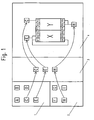
- the left part of the screen according to Fig. 1 is subdivided into an upper area 1 and a lower area 2, wherein in the upper area 1 five encoder symbols A to E and in the lower area 2 four actuator symbols F to I are shown.
- Right to the areas 1 and 2 is followed by a selection box 3, in which encoder symbols and actuator symbols from the areas 1 and 2 can be dragged and dropped.
- selection area 3 encoder and actuator symbols are then available for wiring.
- a safety control consisting of two modules X and Y is shown, wherein the module X has six connection terminals X1 to X6 and the module Y also has six connection terminals Y1 to Y6.
- the modules X, Y of the safety controller can also be selected by means of a suitable method and placed in the screen area 4, so that, in principle, any safety controllers constructed from different modules can be assembled.
- the encoder symbols C and E and the actuator symbol H were selected from the areas 1 and 2 and dragged and dropped into the selection area 3.
- the encoder symbol C is then dragged and dropped from the selection field 3 into the area of the terminal Y3 of the module Y, whereupon a wiring symbol in the form of a line is automatically displayed between the encoder symbol C and the terminal Y3.
- the encoder symbol C is associated with an item description, which indicates that this is a single-channel switch, which can be connected to any digital input of a safety controller.
- it is then checked whether the selected terminal Y3 is a digital input. If this is the case, a corresponding wiring is permitted and the said wiring symbol between the encoder symbol C and the terminal Y3 is shown.
- the encoder symbol E is then dragged and dropped from the selection field 3 into the area of the connection terminals X1, X2 of the module X and placed there.
- the encoder symbol E contains an element description which indicates that this is a dual-channel tested switch. Accordingly, when placing the encoder symbol E according to the invention, it is automatically checked whether the terminals X1 and X2 of the module X are suitable inputs. Furthermore, the output X4 of the module X is automatically selected as a test output, which is then also wired to the encoder symbol E. Ultimately, this results in permissible wiring of the encoder symbol E with the two inputs X1 and X2 as well as with the output X4 of the module X.
- the actuator symbol H which according to its element description relates to a two-channel relay, is drawn in the region of the outputs Y5, Y6 of the module Y.
- the terminals Y5 and Y6 are suitable outputs, whereupon, when the test is positive, wiring symbols are displayed between the actuator symbol H and the terminals Y5, Y6 of the module Y.
- the modules X and Y are the safety controller also stored in each case one known to the programmer element description, which specifies all inputs and outputs of the modules X and Y.
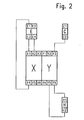
- the wiring diagram After the wiring diagram has been completed by the method steps explained above, it can be printed out on the basis of the information generated in the programmer, the form of the wiring diagram corresponding to FIG Fig. 2 can correspond.
- the encoders C and E and the actuator H are each shown with their physical connection terminals, so that the user is also clear which terminals of the encoder C, E and the actuator H must be connected to the selected terminals of the modules X and Y respectively.
- the selection of the specific connection terminals of the encoders C, E and the actuator H is again based on the element descriptions stored in the encoder symbols C, E and the actuator symbol H. Namely, these element descriptions specify the functions of all the terminals of the encoders C, E and the actuator H.
- Fig. 1 information entered into the programming device is also the same program part of a program for operating the safety controller X, Y created, which is responsible for the evaluation of the signals of the encoder C, E and for the control of the actuator H.
- the in screen area 4 according to Fig. 1 made wiring. Due to this wiring, it is clear that the program part C according to Fig. 4 must evaluate the input Y3 of the module Y, so that the program part C can be assigned in an automated manner by the program device, the input parameter Y3. In a corresponding manner, the program part E is assigned the input parameters X1 and X2 as well as the output parameter X4. Regarding the Program part H is an assignment of the output parameters Y5 and Y6.
- the program parts A, B can be combined to form a single program part AB, which can evaluate both a single-channel switch A and a two-channel switch B. Then, when the two-channel switch B is wired to the safety controller, the programmer automatically selects the program part AB and configures it by means of suitable parameters such that it is suitable for the evaluation of a two-channel switch.
- a configuration could be made such that the program part AB is suitable for evaluating a single-channel switch.
Abstract
Description
Die Erfindung betrifft ein Verfahren zum Programmieren einer mit Gebern und Aktoren zu verschaltenden Sicherheitssteuerung.The invention relates to a method for programming a safety controller to be interconnected with encoders and actuators.
Ein derartiges Verfahren ist aus
Die
Nachteilig an dem bekannten Verfahren ist die Tatsache, dass auch für die Realisierung von sehr einfachen Funktionen für die Auswertung jedes einzelnen Eingangs der Sicherheitssteuerung ein separates Programmmodul ausgewählt und zugeordnet werden muss, wobei dies in gleicher Weise für die Ansteuerung jedes einzelnen Ausgangs gilt. Somit wird das Gesamtprogramm durch die hohe Anzahl der auszuwählenden Programmmodule oftmals unübersichtlich. Insbesondere lassen sich bei der Realisierung von komplexen Funktionen nicht mehr alle ausgewählten Programmmodule auf einer einzelnen Bildschirmseite der Programmieroberfläche darstellen.A disadvantage of the known method is the fact that even for the realization of very simple functions for the evaluation of each individual input of the safety controller, a separate program module must be selected and assigned, which applies in the same way for the control of each individual output. Thus, the overall program is often confused by the high number of program modules to be selected. In particular, when implementing complex functions, it is no longer possible to display all the selected program modules on a single screen page of the programming interface.
Zudem wird dem Programmierer gemäß Stand der Technik im Rahmen der Programmieroberfläche ausschließlich die Struktur des zu erstellenden Programms veranschaulicht, wobei ihm keinerlei Informationen hinsichtlich der Verdrahtung zwischen der Sicherheitssteuerung einerseits und Gebern und Aktoren andererseits vermittelt werden.In addition, according to the state of the art, the programmer in the context of the programming interface exclusively illustrates the structure of the program to be created, whereby no information regarding the wiring between the safety controller on the one hand and encoders and actuators on the other hand is communicated to him.
Zudem ist das bekannte Verfahren nur mit Schwierigkeiten anwendbar, wenn Sicherheitssteuerungen zu programmieren sind, welche unterschiedliche, beispielsweise über Netzwerke miteinander kommunizierende Komponenten aufweisen, da die Programmieroberfläche nicht dazu geeignet ist, den Programmierer darüber zu informieren, an welcher physikalischen Position im Gesamtsystem sich ein bestimmter Eingang oder ein bestimmter Ausgang der Sicherheitssteuerung befindet.In addition, the known method is difficult to apply when programming safety controllers having different components communicating with one another, for example, via networks, since the programming interface is not suitable for informing the programmer of the physical position in the overall system Input or a specific output of the safety controller is located.
Eine Aufgabe der Erfindung besteht darin, ein Verfahren der eingangs genannten Art bereitzustellen, welches einerseits das jeweils gewünschte Programm konfiguriert und/oder erstellt, andererseits aber gleichzeitig Informationen hinsichtlich der vorzunehmenden Verdrahtung von Sicherheitssteuerung, Gebern und Aktoren liefert. Dabei soll insbesondere das Konfigurieren und/oder Erstellen des Programms auf einfache und übersichtliche Art und Weise ermöglicht werden, so dass Fehler weitestgehend ausgeschlossen werden. Schließlich soll vorzugsweise auch ermöglicht werden, Programme für Sicherheitssteuerungen bereitzustellen, die aus mehreren, dezentral angeordneten Programmteilen bestehen, ohne dass hierunter die Übersichtlichkeit beim Konfigurieren und/oder Erstellen des Programms leidet.An object of the invention is to provide a method of the type mentioned above, which on the one hand configures and / or creates the respective desired program, but on the other hand simultaneously provides information regarding the wiring to be made of safety controller, encoders and actuators. In particular, the configuration and / or creation of the program should be made possible in a simple and clear manner, so that errors largely be excluded. Finally, preferably also be made possible to provide programs for safety controls, which consist of several, decentralized program parts, without this under the clarity of configuring and / or creating the program suffers.
Erfindungsgemäß wird diese Aufgabe gemäß einer ersten Variante dadurch gelöst, dass zuerst ein Verdrahtungsplan erstellt wird, indem
- die Sicherheitssteuerung mit ihren Anschlussklemmen zumindest schematisch auf einer graphischen Programmieroberfläche dargestellt wird,
- Geber und Aktoren anhand von Geber- und Aktorsymbolen ausgewählt werden, und
- Verdrahtungssymbole auf der Programmieroberfläche dargestellt werden, welche die Geber- und Aktorsymbole mit den ihnen zugeordneten Anschlussklemmen verbinden,
- automatisch Programmteile aktiviert und/oder zusammengestellt werden, die für die Auswertung der ausgewählten Geber und die Ansteuerung der ausgewählten Aktoren vorgesehen sind, und
- diesen Programmteilen automatisch Parameter zugeordnet werden, welche denjenigen Anschlussklemmen entsprechen, mit denen die jeweiligen Geber- und Aktorsymbole verbunden sind.
- the safety controller with its connection terminals is shown at least schematically on a graphical programming interface,
- Encoders and actuators are selected based on encoder and actuator symbols, and
- Wiring symbols are displayed on the programming interface, which connect the encoder and actuator symbols with their associated terminals,
- automatically program parts are activated and / or assembled, which are provided for the evaluation of the selected encoder and the control of the selected actuators, and
- These program parts are automatically assigned parameters that correspond to those terminals with which the respective encoder and actuator symbols are connected.
Im Unterschied zum Stand der Technik wird also erfindungsgemäß in einem ersten Schritt unter Nutzung einer grafischen Programmieroberfläche lediglich ein Verdrahtungsplan erstellt, welcher angibt, welche Anschlussklemmen der Sicherheitssteuerung mit welchen Gebern und Aktoren verdrahtet werden sollen. Aufgrund dieses Verdrahtungsplans ist es bereits bekannt, welche Geber und Aktoren für die jeweilige Anwendung eingesetzt werden, so dass mittels des erfindungsgemäßen Verfahrens in einem zweiten Schritt nach dem Erstellen des Verdrahtungsplans automatisch diejenigen Programmteile programmiert werden können, die dafür vorgesehen sind, die ausgewählten Geber auszuwerten und die ausgewählten Aktoren anzusteuern. Darüber hinaus ist es aufgrund der vorgenommenen Verdrahtung auch bereits bekannt, mit welchen konkreten Anschlussklemmen die ausgewählten Geber und Aktoren zu verbinden sind, so dass in den genannten Programmteilen automatisch Parameter gesetzt werden können, die den jeweiligen Anschlussklemmen entsprechen.In contrast to the prior art, according to the invention, in a first step using a graphical programming interface, only a wiring plan is created which indicates which terminals of the safety controller are to be wired with which encoders and actuators. Because of this wiring diagram, it is already known which encoders and actuators for each application can be used, so that by means of the method according to the invention in a second step after the creation of the wiring diagram those program parts can be programmed which are intended to evaluate the selected donors and to control the selected actuators. In addition, due to the wiring already made, it is also already known with which specific connection terminals the selected encoders and actuators are to be connected so that parameters can be automatically set in the program sections mentioned that correspond to the respective connection terminals.
Es ist erfindungsgemäß also in Kenntnis des Verdrahtungsplans bereits möglich, in komplett automatisierter Weise Programmteile zu programmieren und diese auch hinsichtlich der ausgewählten Anschlussklemmen zu parametrieren, so dass derjenige Programmbereich, der für die Auswertung der Geber und die Ansteuerung der Aktoren zuständig ist, praktisch vollautomatisch programmiert wird. Es ist dann lediglich in einem weiteren Schritt noch möglich, in geeigneter Weise festzulegen, wie ausgewertete Gebersignale logisch miteinander verknüpft werden sollen und welchen Aktoren die Verknüpfungsergebnisse zuzuordnen sind (Logikprogrammierung).In accordance with the invention, knowing the wiring diagram, it is thus already possible to program program parts in a completely automated manner and to parameterize these also with regard to the selected connection terminals, so that the program area which is responsible for the evaluation of the sensors and the control of the actuators is practically programmed fully automatically becomes. It is then only possible in a further step to determine in a suitable manner how evaluated encoder signals are to be logically linked to one another and to which actuators the logic results are to be assigned (logic programming).
Im Rahmen der Erfindung wird also erreicht, dass alleine durch das grafisch unterstützte Erstellen eines Verdrahtungsplans bereits wesentliche Teile des Programms für den Betrieb der Sicherheitssteuerung programmiert werden, ohne dass der Programmierer hierfür zusätzliche Schritte ausführen muss. Dies führt zum einen zu einer wesentlich erhöhten Wirtschaftlichkeit des gesamten Verfahrens, zum anderen wird durch die genannte Automatisierung erreicht, dass eine fehlerfreie Erzeugung der automatisiert erstellten Programmteile sichergestellt ist.In the context of the invention is thus achieved that even by the graphically assisted creation of a wiring plan already essential parts of the program for the operation of the safety control can be programmed without the programmer has to perform additional steps for this purpose. On the one hand, this leads to a substantially increased cost-effectiveness of the entire method, on the other hand, the automation mentioned achieves that error-free generation of the automatically generated program parts is ensured.
Anders als beim eingangs zitierten Dokument
Erfindungsgemäße Programmteile, die für die Auswertung der ausgewählten Geber zuständig sind, übernehmen zum Beispiel die Konvertierung eines vom Geber gelieferten zweikanaligen (ambivalenten oder äquivalenten) Signals in ein einzelnes Signal oder eine Wandlung eines analogen in ein digitales Signal, welches dann im Rahmen einer Logikverknüpfung weiterverarbeitbar ist. Ebenso können solche Programmteile z.B. von Gebern gelieferte Testsignale auswerten oder dafür sorgen, dass geeignete Testsignale an einen Geber gesandt werden.Program parts according to the invention, which are responsible for evaluating the selected encoders, take over, for example, the conversion of a two-channel (ambivalent or equivalent) signal supplied by the encoder into a single signal or a conversion of an analog signal into a digital signal, which can then be further processed as part of a logic link is. Likewise, such program parts may e.g. Evaluate test signals supplied by encoders or ensure that appropriate test signals are sent to an encoder.
Programmteile die für die Ansteuerung der ausgewählten Aktoren zuständig sind, können beispielsweise von einer Logikverknüpfung oder einem Steuerungseingang gelieferte einzelne Signale in zweikanalige (ambivalente oder äquivalente), über zwei Ausgangsklemmen der Sicherheitssteuerung auszugebende Signale konvertieren. Ebenso kann z.B. eine Anpassung der elektrischen Signaleigenschaften vorgenommen werden, oder es kann eine Wandlung eines digitalen Signals in ein analoges Signal erfolgen.Program parts which are responsible for controlling the selected actuators can, for example, convert individual signals delivered by a logic link or a control input into two-channel (ambivalent or equivalent) signals to be output via two output terminals of the safety controller. Likewise, for example, an adaptation of electrical signal properties are made, or it can be a conversion of a digital signal into an analog signal.
Besonders bevorzugt ist es im Rahmen der Erfindung, wenn die Relativpositionen der auf der grafischen Programmieroberfläche dargestellten Anschlussklemmen deren tatsächlichen physikalischen Relativpositionen entsprechen. Vorteilhaft ist es dabei, wenn ein komplettes physikalisches Abbild der Sicherheitssteuerung mit ihren Anschlussklemmen auf der grafischen Programmieroberfläche dargestellt wird. Durch diese Maßnahmen wird erreicht, dass dem Programmierer bereits beim Erstellen des Verdrahtungsplans in sehr anschaulicher Weise klar wird, welche Anschlussklemmen jeweils zu kontaktieren sind, da die auf der Programmieroberfläche sichtbaren Anschlussklemmen exakt in der gleichen Weise angeordnet sind, wie sie an der gegenständlich und physikalisch vorhandenen Sicherheitssteuerung angebracht sind.In the context of the invention, it is particularly preferred if the relative positions of the terminals represented on the graphical programming interface correspond to their actual physical relative positions. It is advantageous if a complete physical image of the safety controller with its terminals on the graphical programming interface is displayed. By means of these measures it is achieved that the programmer, when creating the wiring diagram, becomes very clearly aware of which terminals are to be contacted in each case, since the terminals visible on the programming surface are arranged exactly in the same way as they physically and physically existing safety control are installed.
Der erfindungsgemäße Programmiervorgang, der sich für den Programmierer im Prinzip im Erstellen des Verdrahtungsplans erschöpft, kann auf beliebigen Programmiergeräten durchgeführt werden. Beispielsweise bietet sich der Einsatz von PCs, Laptops oder Handheld-Geräten an.The programming process according to the invention, which in principle is exhausting for the programmer in creating the wiring diagram, can be carried out on any programming devices. For example, the use of PCs, laptops or handheld devices offers.
In besonders übersichtlicher Weise lässt sich der Programmiervorgang durchführen, wenn eine Menge von verfügbaren Geber- und/oder Aktorsymbolen auf der Programmieroberfläche dargestellt wird und aus dieser Menge diejenigen Geber- und/oder Aktorsysmbole ausgewählt werden, welche den jeweils benötigten Gebern und/oder Aktoren entsprechen. Eine solche Auswahl kann beispielsweise mittels Drag and Drop oder mittels eines Pull-Down-Menüs erfolgen. Nach der Auswahl werden die Symbole dann in den Bereich derjenigen Anschlussklemmen der auf der Programmieroberfläche dargestellten Sicherheitssteuerung gezogen, an die entsprechenden Geber/Aktoren angeschlossen werden sollen. Anschließend kann dann nach erfolgter Auswahl bzw. Positionierung der Geber-und/oder Aktorsymbole automatisch die jeweils erforderliche Verdrahtung zwischen Gebern und/oder Aktoren einerseits und Sicherheitssteuerung andererseits auf der Programmieroberfläche dargestellt werden. In üblicher Weise wird eine solche Verdrahtung mittels einfacher, linienförmiger Verdrahtungssymbole visualisiert. Es sind jedoch auch beliebige andere Visualisierungsmöglichkeiten denkbar, solange sichergestellt ist, dass dem Programmierer ersichtlich wird, welche Anschlussklemmen der Sicherheitssteuerung mit welchen Gebern bzw. Aktoren elektrisch kontaktiert werden müssen.In a particularly clear way, the programming process can be performed when a set of available encoder and / or actuator symbols is displayed on the programming interface and from this set those donor and / or Aktorsysmbole be selected, which correspond to the respective required donors and / or actuators , Such a selection can be made for example by means of drag and drop or by means of a pull-down menu. After selection, the symbols are then drawn into the area of those terminals of the safety controller shown on the programming interface, to which corresponding encoders / actuators are to be connected. Subsequently, after the selection or positioning of the encoder and / or actuator symbols, the respective required wiring between encoders and / or actuators on the one hand and the safety controller on the other hand can be displayed automatically on the programming interface. In the usual way, such a wiring is visualized by means of simple, line-shaped wiring symbols. However, any other visualization options are conceivable as long as it is ensured that the programmer will see which terminals of the safety controller must be electrically contacted with which donors or actuators.
Die auf der Programmieroberfläche dargestellten Anschlussklemmen der Sicherheitssteuerung können alle an einer einzelnen, in einem einzigen Gehäuse untergebrachten Steuerungskomponente vorgesehen sein. Es ist jedoch auch möglich, dass die dargestellten Anschlussklemmen der Sicherheitssteuerung mehreren physikalisch voneinander getrennten Einheiten bzw. Modulen zugeordnet sind. Derartige getrennte Einheiten sind dann bevorzugt kommunizierend miteinander verbunden, wobei eine solche Verbindung beispielsweise mittels eines Feldbus oder einer Backplane (Karte mit verschiedenen Steckplätzen) realisiert werden kann. Physikalisch voneinander getrennte aber kommunizierend miteinander verbundene Einheiten der Sicherheitssteuerung können beliebige Aufgaben übernehmen wobei die Einheiten nicht zwangsläufig aktiv intelligente Steuerungsaufgaben übernehmen müssen. Beispielsweise ist es möglich, separate Einheiten vorzusehen, die lediglich physikalische Ein- und Ausgänge der Sicherheitssteuerung bereitstellen.The safety control terminals shown on the programming interface may all be provided on a single control component accommodated in a single housing. However, it is also possible that the illustrated terminals of the safety controller are assigned to a plurality of physically separate units or modules. Such separate units are then preferably connected communicatively with each other, wherein such a connection can be realized for example by means of a fieldbus or a backplane (card with different slots). Physically separate but communicatively interconnected units of the safety controller can take on any task whereby the units do not necessarily have to actively take over intelligent control tasks. For example, it is possible to provide separate units that provide only physical inputs and outputs of the safety controller.
Besonders vorteilhaft ist es, wenn nach dem Erstellen des Verdrahtungsplans ein Ausdrucken oder Anzeigen dieses Plans erfolgt, wobei auf dem Plan sämtliche Anschlussklemmen von Sicherheitssteuerung, Gebern und Aktoren, jeweils entsprechend ihrer physikalischen Anordnung, einschließlich der gewählten Verbindungen dieser Anschlussklemmen dargestellt sind. Von Vorteil ist es, wenn die Anschlussklemmen zudem auf dem Verdrahtungsplan mit ihrer jeweils physikalisch am Gerät vorhandenen Bezeichnung bzw. Kennzeichnung versehen sind. Aufgrund des genannten Plans ist der Fachmann dann dazu in der Lage, ohne irgendwelche weiteren Informationen eine komplette und korrekte Verdrahtung von Sicherheitssteuerung, Gebern und Aktoren vorzunehmen, wobei dies insbesondere auch dann gilt, wenn die Sicherheitssteuerung aus mehreren dezentralen Komponenten besteht, die dann dementsprechend auf dem Plan ebenfalls getrennt voneinander dargestellt werden.It is particularly advantageous if after the creation of the wiring diagram, a printout or display of this plan takes place, wherein on the Plan all terminals of the safety controller, encoders and actuators, each according to their physical arrangement, including the selected connections of these terminals are shown. It is advantageous if the terminals are also provided on the wiring diagram with their respective physically present on the device name or marking. On the basis of the above-mentioned plan, the person skilled in the art is then able to carry out complete and correct wiring of the safety controller, encoders and actuators without any further information, this also applies if the safety controller consists of several decentralized components which then apply accordingly The plan can also be displayed separately from each other.
Es kann auch zuerst eine physikalische Verdrahtung der Anschlussklemmen der Sicherheitssteuerung mit den jeweils benötigten Gebern und Aktoren vorgenommen werden, woraufhin von einem Programmiergerät erkannt wird, welche Geber und Aktoren verdrahtet wurden, und anschließend ein Programm konfiguriert oder erstellt werden, indem automatisch Programmteile aktiviert oder zusammengestellt werden, die für die Auswertung der verdrahteten Geber und die Ansteuerung der verdrahteten Aktoren vorgesehen sind, wobei diesen Programmteilen automatisch Parameter zugeordnet werden, welche denjenigen Anschlussklemmen entsprechen, mit denen die jeweiligen Geber und Aktoren verbunden sind.It is also possible first to perform a physical wiring of the connection terminals of the safety controller with the respective required encoders and actuators, whereupon a programming device recognizes which encoders and actuators have been wired, and then a program can be configured or created by automatically activating or assembling program parts are provided for the evaluation of wired encoders and the control of the wired actuators, these program parts are automatically assigned parameters corresponding to those terminals to which the respective encoders and actuators are connected.
Es kann also gleich direkt die physikalische Verdrahtung der Anschlussklemmen der Sicherheitssteuerung mit den jeweils benötigten Gebern und Aktoren vorgenommen werden, was sich insbesondere dann anbietet, wenn vergleichsweise wenige Komponenten miteinander zu verdrahten sind.It can therefore be made directly the physical wiring of the terminals of the safety controller with the respective required donors and actuators, which is particularly appropriate, when comparatively few components are to be wired together.
Die vorgenommene Verdrahtung und die angeschlossenen Geber und Aktoren werden dann automatisch von einem Programmiergerät erkannt, so dass dem Programmiergerät eine Information dahingehend vorliegt, welche Geber und welche Aktoren mit welchen Anschlussklemmen der Sicherheitssteuerung kontaktiert sind. Bei dem Programmiergerät kann es sich um ein externes Programmiergerät, beispielsweise einen PC, Laptop oder Handheld handeln, es ist jedoch ebenso möglich, die Sicherheitssteuerung selbst oder einen Teil der Sicherheitssteuerung als Programmiergerät auszubilden.The wiring and the connected encoders and actuators are then automatically detected by a programmer, so that the programmer information exists as to which encoder and which actuators are contacted with which terminals of the safety controller. The programming device can be an external programming device, for example a PC, laptop or handheld, but it is also possible to design the safety control itself or a part of the safety control as a programming device.
Durch das Programmiergerät wird anschließend dann in Kenntnis der vorgenommenen Verdrahtung und der angeschlossenen Geber und Aktoren ein Programm konfiguriert oder erstellt, wobei dies in der gleichen Weise vollzogen wird, wie bei der ersten erfindungsgemäßen Variante. Es werden also automatisch Programmteile aktiviert oder zusammengestellt, die für die Auswertung der bereits verdrahteten Geber und die Ansteuerung der bereits verdrahteten Aktoren vorgesehen sind, wobei diesen Programmteilen automatisch Parameter zugeordnet werden, welche denjenigen Anschlussklemmen der Sicherheitssteuerung entsprechen, die mit den bereits verdrahteten Gebern und Aktoren verbunden sind.The programmer then configures or creates a program with knowledge of the wiring made and the connected sensors and actuators, this being done in the same way as in the first variant according to the invention. It automatically program parts are activated or put together, which are provided for the evaluation of the already wired encoder and the control of the already wired actuators, these program parts are automatically assigned parameters that correspond to those terminals of the safety controller, with the already wired encoders and actuators are connected.
Mit der ersten erfindungsgemäßen Variante wird also die Verdrahtung zuerst theoretisch mittels eines geeigneten Programmiergeräts vorgenommen, so dass dem Programmiergerät ohnehin alle verwendeten Anschlussklemmen von Sicherheitssteuerung, Gebern und Aktoren bekannt sind. Besonders bevorzugt ist es, wenn jedem Geber und jedem Aktor in Form eines Datensatzes eine geber- oder aktorspezifische Elementbeschreibung zugeordnet ist, welche Eigenschaften des jeweiligen Gebers Besonders bevorzugt ist es, wenn jedem Geber und jedem Aktor in Form eines Datensatzes eine geber- oder aktorspezifische Elementbeschreibung zugeordnet ist, welche Eigenschaften des jeweiligen Gebers oder Aktors definiert. Im Rahmen einer solchen Elementbeschreibung kann in Form eines Datensatzes beispielsweise festgelegt werden, dass es sich bei einem bestimmten Geber um einen Notaus-Taster handelt, der auf zwei separaten Kanälen ambivalente Signale liefert und mit einem Testsignal versorgt werden muss. Wenn dem Programmiergerät in erfindungsgemäßer Weise eine solche Elementbeschreibung eines ausgewählten Gebers bekannt ist, kann während des Programmiervorgangs sichergestellt werden, dass der entsprechende Geber nur an jeweils geeignete Eingangsklemmen der Sicherheitssteuerung angeschlossen werden kann. Ein fehlerhafter Anschluss kann vom Programmiergerät von vorne herein nicht zugelassen werden oder es kann nach einem fehlerhaften Anschluss ein Warnsignal ausgegeben werden.Thus, with the first variant according to the invention, the wiring is first theoretically carried out by means of a suitable programming device, so that the programming device is in any case known all the terminals of the safety controller, encoders and actuators used. It is particularly preferred if each encoder and each actuator in the form of a data record is assigned a donor or actuator-specific element description, which properties of the respective donor It is particularly preferred if each encoder and each actor in the form of a data record is assigned an encoder-specific or actuator-specific element description which defines properties of the respective transmitter or actuator. In the context of such an element description, it can be determined in the form of a data set, for example, that a particular transmitter is an emergency stop button which supplies ambivalent signals on two separate channels and must be supplied with a test signal. If the programming device according to the invention such an element description of a selected encoder is known, it can be ensured during the programming process that the corresponding encoder can only be connected to each appropriate input terminals of the safety controller. A faulty connection can not be approved by the programmer from the outset, or a warning signal can be output after a faulty connection.
Die Elementbeschreibung kann jedoch darüber hinaus auch dazu dienen, den eigentlichen Programmiervorgang durchzuführen. Aufgrund der Elementbeschreibung ist nämlich grundsätzlich bekannt, welche Funktionen ein Programmteil ausführen muss, welcher für die Auswertung eines jeweiligen Gebers oder die Ansteuerung eines jeweiligen Aktors zuständig ist. Dementsprechend kann beispielsweise in Abhängigkeit von der Elementbeschreibung ein spezieller Programmteil aktiviert oder dem zu erstellenden Programm hinzugefügt werden, welcher die jeweils erforderlichen Funktionen für die Auswertung eines jeweiligen Gebers oder die Ansteuerung eines jeweiligen Aktors besitzt. Ebenso ist es jedoch möglich, dass aus der Elementbeschreibung Parameter abgeleitet werden, die einen geeigneten, im zu erstellenden Programm bereits vorhandenen Programmteil lediglich derart konfigurieren, dass er dazu geeignet ist, den jeweiligen Geber oder Aktor auszuwerten oder anzusteuern. Wenn im letztgenannten Fall beispielsweise ein Programmteil sowohl für eine einkanalige als auch für eine zweikanalige Auswertung geeignet ist, kann mittels eines aus der Elementbeschreibung abgeleiteten Parameters festgelegt werden, ob dieser Programmteil im konkreten Anwendungsfall eine einkanalige oder eine zweikanalige Auswertung durchführen soll.However, the element description may also serve to perform the actual programming operation. Because of the element description, it is basically known which functions a program part must execute, which is responsible for the evaluation of a respective transmitter or the activation of a respective actuator. Accordingly, for example, depending on the element description, a special program part can be activated or added to the program to be created, whichever is required Has functions for the evaluation of a respective encoder or the control of a respective actuator. However, it is likewise possible for parameters to be derived from the element description which merely configure a suitable program part already present in the program to be created such that it is suitable for evaluating or controlling the respective encoder or actuator. If in the last-mentioned case, for example, a program part is suitable both for a single-channel and for a two-channel evaluation, it can be determined by means of a parameter derived from the element description whether this program part should carry out a single-channel or two-channel evaluation in the specific application.
Aufgrund der Elementbeschreibung kann also zum einen die vorgenommene Verdrahtung überprüft werden, zum anderen können auch die jeweils benötigten Programmteile ausgewählt, aktiviert oder konfiguriert werden. Derartigen Programmteilen können in der Folge dann vom Programmgerät in automatisierter Weise noch Parameter zugeordnet werden, die denjenigen Anschlussklemmen der Sicherheitssteuerung entsprechen, an die der jeweilige Geber oder Aktor angeschlossen ist. Dies ist nötig, da die aufgrund der Elementbeschreibung aktivierten oder konfigurierten Programmteile zwar grundsätzlich dazu geeignet sind, die für den jeweiligen Geber oder Aktor erforderlichen Funktionen auszuführen, wobei aber allein aufgrund der Elementbeschreibung noch nicht bekannt ist, an welche konkreten Anschlussklemmen der Sicherheitssteuerung die jeweiligen Geber oder Aktoren angeschlossen wurden. Diese Information liegt jedoch - wie bereits erwähnt - im Programmiergerät aufgrund des Verdrahtungsplans oder der bereits vorgenommenen Verdrahtung vor, so dass das Programmiergerät den aktivierten oder konfigurierten Programmteilen entsprechende Parameter zuordnen kann. Auf diese Weise wird sichergestellt, dass die korrekten Eingänge der Sicherheitssteuerung ausgewertet und die korrekten Ausgänge der Sicherheitssteuerung angesteuert werden.On the one hand, the wiring made can be checked on the basis of the element description; on the other hand, the respectively required program parts can also be selected, activated or configured. Such program parts can then be assigned by the program device in an automated manner still parameters that correspond to those terminals of the safety controller to which the respective encoder or actuator is connected. This is necessary because the program parts activated or configured on the basis of the element description are in principle suitable for carrying out the functions required for the respective encoder or actuator, but due to the element description it is not yet known to which specific terminals of the safety control the respective encoders or actuators were connected. However, this information is - as already mentioned - in the programmer due to the wiring diagram or the already made wiring, so that the programmer can assign the activated or configured program parts corresponding parameters. This will ensure that the correct inputs of the safety controller are evaluated and the correct outputs of the safety controller are controlled.
Die Elementbeschreibungen können bereits zu Beginn des erfindungsgemäßen Verfahrens im Programmiergerät hinterlegt bzw. gespeichert sein. Alternativ ist es jedoch auch möglich, dass die Elementbeschreibungen in den zugehörigen Gebern und Aktoren gespeichert sind, von wo aus sie zum Zweck des Programmierens drahtgebunden oder drahtlos in das Programmiergerät übertragen werden. Bei dem Programmiergerät kann es sich wiederum um ein externes Gerät, beispielsweise einen PC, Laptop oder Handheld handeln. Zudem ist es aber auch möglich, die Sicherheitssteuerung selbst als Programmiergerät auszubilden. Im letztgenannten Fall ist es dann möglich, dass sich die Sicherheitssteuerung alleine aufgrund des Anschlusses der jeweils benötigten Geber und Aktoren praktisch selbst programmiert, zumindest soweit die Auswertung der Eingänge und die Ansteuerung der Ausgänge betroffen ist.The element descriptions can already be stored or stored at the beginning of the method according to the invention in the programming device. Alternatively, however, it is also possible that the element descriptions are stored in the associated encoders and actuators, from where they are transmitted for the purpose of programming wired or wireless in the programmer. The programming device can again be an external device, for example a PC, laptop or handheld. In addition, it is also possible to design the safety controller itself as a programming device. In the latter case, it is then possible that the safety controller practically programmed itself alone due to the connection of the required encoder and actuators, at least as far as the evaluation of the inputs and the control of the outputs is concerned.
Die Elementbeschreibung der Geber kann zumindest eine der im Folgenden genannten geberspezifischen Informationen beinhalten:
- Anzahl der auszuwertenden Kanäle,
- Anforderungen an die anzuschließenden Eingangsklemmen der Sicherheitssteuerung,
- Art der Auswertung (äquivalent/ ambivalent),
- Testkonfiguration,
- vorhandene Anschlussklemmen,
- physikalische Anordnung der Anschlussklemmen,
- Geberkennzeichnung.
- Number of channels to be evaluated,
- Requirements for the safety controller input terminals to be connected,
- Type of evaluation (equivalent / ambivalent),
- Test configuration
- existing terminals,
- physical arrangement of the terminals,
- Donor identification.
Wenn die Elementbeschreibung Informationen über die Anzahl der auszuwertenden Kanäle beinhaltet, kann - wie bereits erläutert - eine fehlerhafte Verdrahtung bereits durch das Programmiergerät ausgeschlossen werden, da beispielsweise bei zwei auszuwertenden Kanälen eine Fehlermeldung erzeugt werden kann, wenn lediglich ein Kanal angeschlossen wird. Entsprechendes gilt, wenn die Elementbeschreibung Informationen über die Anforderungen an die anzuschließenden Eingangsklemmen der Sicherheitssteuerung beinhaltet. Aufgrund dieser Information kann vom Programmiergerät beispielsweise eine Fehlermeldung abgesetzt werden, wenn ein Analogwertgeber an einen Digitaleingang der Sicherheitssteuerung angeschlossen wird.If the element description contains information about the number of channels to be evaluated, faulty wiring can already be excluded by the programming device, as, for example, with two channels to be evaluated, an error message can be generated if only one channel is connected. The same applies if the element description contains information about the requirements for the input terminals of the safety controller to be connected. On the basis of this information, an error message can be issued by the programming device, for example, when an analog value transmitter is connected to a digital input of the safety controller.
Die in der Elementbeschreibung gegebenenfalls vorhandene Information "Testkonfiguration" kann festlegen; mit wie vielen und/oder welchen Ausgangsanschlussklemmen der Sicherheitssteuerung der Geber zu verdrahten ist. Eine solche Elementbeschreibung ist grundsätzlich einem Geber zugeordnet, welcher von der Sicherheitssteuerung mit zumindest einem Testsignal versorgt werden muss, so dass ein solcher Geber nicht nur mit zumindest einer Eingangsanschlussklemme der Sicherheitssteuerung sondern auch mit zumindest einer Ausgangsanschlussklemme der Sicherheitssteuerung zu verdrahten ist.The "Test configuration" information that may be present in the element description can specify; with how many and / or which output terminals of the safety controller the encoder is to be wired. Such an element description is fundamentally assigned to a sensor which must be supplied with at least one test signal by the safety controller so that such an encoder must be wired not only to at least one input terminal of the safety controller but also to at least one output terminal of the safety controller.
Die Elementbeschreibung der Aktoren kann zumindest eine der im Folgenden genannten aktorspezifischen Informationen beinhalten:
- Anzahl der anzusteuernden Kanäle,
- Anforderungen an die anzuschließenden Ausgangsklemmen der Sicherheitssteuerung,
- Art der Ansteuerung (äquivalent/ ambivalent),
- vorhandene Anschlussklemmen,
- physikalische Anordnung der Anschlussklemmen,
- Aktorkennzeichnung.
- Number of channels to be controlled,
- Requirements for the output terminals of the safety controller to be connected,
- Type of control (equivalent / ambivalent),
- existing terminals,
- physical arrangement of the terminals,
- Aktorkennzeichnung.
Die in der Elementbeschreibung von Geber oder Aktor beinhaltete Information bezüglich der vorhandenen Anschlussklemmen und/oder der physikalischen Anordnung dieser Anschlussklemmen dient dazu, nach Erstellen des Verdrahtungsplans auch einen kompletten Verdrahtungsplan ausdrucken zu können, welcher nicht nur die Sicherheitssteuerung sondern auch alle ausgewählten Geber und Aktoren mit ihren jeweiligen Anschlussklemmen darstellt. Zudem wird es für bestimmte Anwendungsfälle auch für den Programmierer möglich, bei der Verdrahtung von Gebern und Aktoren mit der Sicherheitssteuerung bestimmte Anschlussklemmen von Gebern und Aktoren auszuwählen, sofern hier mehrere Möglichkeiten zur Verfügung stehen. Zudem können alle Anschlussklemmen der Geber und Aktoren im Verdrahtungsplan mit ihrer jeweils physikalisch am Gerät vorhandenen Bezeichnung bzw. Kennzeichnung versehen werden, sofern diese Bezeichnungen bzw. Kennzeichnungen Bestandteil der Anschlussklemmeninformation der Elementbeschreibung sind.The information contained in the element description of the encoder or actuator with respect to the existing terminals and / or the physical arrangement of these terminals is used to create a complete wiring diagram after creating the wiring diagram, which not only the safety controller but also all selected sensors and actuators represents their respective terminals. In addition, for certain applications, it is also possible for the programmer to select specific connection terminals of encoders and actuators when wiring encoders and actuators with the safety controller, provided that several options are available here. In addition, all connection terminals of the encoders and actuators can be provided in the wiring diagram with their respective physically present on the device name or label, provided that these names or labels are part of the terminal information of the element description.
Die in der Elementbeschreibung von Gebern und Aktoren gegebenenfalls vorhandene Information "Anforderungen an die anzuschließenden Ein- bzw. Ausgangsklemmen der Sicherheitssteuerung können sowohl elektrische als auch physikalische Anforderungen betreffen. Elektrische Anforderungen definieren z.B. ob digitale oder analoge Signale übertragen werden oder mit welchen Strömen, Spannungen, Kapazitäten, etc. die jeweiligen Klemmen kompatibel sein müssen, um mit den jeweiligen Gebern oder Aktoren kommunizieren zu können. Physikalische Eigenschaften können z.B. Drahtquerschnitte oder Steckertypen der Geber- bzw. Aktorkabel definieren.The information which may be present in the element description of encoders and actuators "Requirements for the safety control input or output terminals to be connected can relate to both electrical and physical requirements." Define electrical requirements, for example, whether digital or analog signals are transmitted or with what currents, voltages, Capacitance, etc. the respective terminals must be compatible in order to be able to communicate with the respective encoders or actuators Physical properties can, for example, define wire cross-sections or connector types of the encoder or actuator cables.
Die in der Elementbeschreibung von Gebern und Aktoren gegebenenfalls vorhandene Information "Geberkennzeichnung" bzw. "Aktorkennzeichnung" kann vom Programmierer in einer gewünschten Weise verändert werden, so dass hier eine jeweils passende verbale Beschreibung von Gebern und Aktoren wählbar ist.The optionally present in the element description of encoders and actuators information "encoder identification" or "Aktorkennzeichnung" can be changed by the programmer in a desired manner, so that here a suitable verbal description of encoders and actuators is selectable.
Im Rahmen der Erfindung können nicht nur den Gebern und Aktoren Elementbeschreibungen zugeordnet werden, vielmehr ist es auch möglich, dass zumindest einem, bevorzugt jedem Modul der Sicherheitssteuerung in Form eines Datensatzes eine modulspezifische Elementbeschreibung zugeordnet ist, welche Eigenschaften des jeweiligen Moduls definiert. Eine solche Elementbeschreibung kann dazu dienen, zu überprüfen, ob ein mit bestimmten Gebern oder Aktoren verdrahtetes Modul auch die Eigenschaften besitzt, die jeweiligen Geber auszuwerten bzw. die jeweiligen Aktoren anzusteuern. Sollte dies nicht der Fall sein, kann im Rahmen des Programmiervorgangs wiederum eine Fehlermeldung abgesetzt werden. Zudem kann eine solche Elementbeschreibung Informationen über alle vorhandenen Anschlussklemmen und/oder über die physikalische Anordnung der Anschlussklemmen eines Moduls beinhalten.In the invention, not only the donors and actuators element descriptions can be assigned, but it is also possible that at least one, preferably each module of the safety controller in the form of a data set is associated with a module-specific element description, which defines properties of each module. Such an element description can serve to check whether a module wired with specific encoders or actuators also has the properties of evaluating the respective encoders or of controlling the respective actuators. If this is not the case, an error message can again be issued during the programming process. In addition, such an item description may include information about all existing terminals and / or about the physical location of the terminals of a module.
Bei einer bevorzugten Ausführungsform kann aufgrund der Elementbeschreibung eines Moduls auch eine spezielle Konfiguration eines Gebers oder Aktors vorgenommen werden. Wenn beispielsweise eine Eingangsanschlussklemme eines Moduls ein Testsignal mit bestimmten Testpulsen von einem Geber fordert und der Geber unterschiedliche Testpulse liefern kann, ist es möglich, den Geber durch das Programmiergerät so zu konfigurieren, dass er die von der Eingangsanschlussklemme des Moduls geforderten Testpulse liefert.In a preferred embodiment, a specific configuration of a transmitter or actuator can be made due to the element description of a module. For example, if an input terminal of a module requests a test signal with certain test pulses from a sensor and the encoder can provide different test pulses, it is possible to configure the encoder to provide the test pulses required by the module's input terminal.
Aufgrund des erfindungsgemäßen Verdrahtungsplans und allen vorhandenen Elementbeschreibungen liegt im Programmiergerät eine Komplettinformation bezüglich des konkreten Gesamtsystems vor, die insbesondere bei der auf das erfindungsgemäße Verfahren folgenden Logikprogrammierung sehr vorteilhaft verwertet werden kann. Im Rahmen der Logikprogrammierung wird festgelegt, welche der ausgewerteten Gebersignale in welcher Weise logisch miteinander verknüpft werden sollen und welchen Aktoren die Verknüpfungsergebnisse zuzuordnen sind. Durch die genannte Komplettinformation ist bei der Logikprogrammierung bekannt, welche Anschlussklemmen der Sicherheitssteuerung mit welchen Gebern und Aktoren verbunden sind und welche Eigenschaften die entsprechenden Ein- und Ausgangssignale der Sicherheitssteuerung haben. So kann die vorgenommene Logikprogrammierung problemlos automatisch auf Plausibilität geprüft werden, wodurch Fehlprogrammierungen wirksam verhindert werden.Due to the wiring diagram according to the invention and all existing element descriptions is in the programmer complete information with respect to the concrete overall system, which can be utilized very advantageously, in particular in the logic programming following the method according to the invention. In the context of logic programming, it is determined which of the evaluated encoder signals should be logically linked to each other in which way and to which actuators the logic results are to be assigned. By said complete information is known in logic programming, which terminals of the safety controller are connected to which donors and actuators and which properties have the corresponding input and output signals of the safety controller. Thus, the logic programming can easily be automatically checked for plausibility, which malfunctioning programs are effectively prevented.
Das Programmtool für die Durchführung der erfindungsgemäßen Programmierung kann bevorzugt in einem Speicher der Sicherheitssteuerung hinterlegt und vor dem Beginn des Programmierens in ein Programmiergerät geladen werden. Als Programmiergerät können auch in diesem Fall beispielsweise PCs, Laptops oder Handheld-Geräte eingesetzt werden. Das Laden des Programmiertools aus der Sicherheitssteuerung in ein Programmiergerät bedingt auf vorteilhafte Weise, dass vor Durchführung der Programmierung keine separate Installation des Programmiertools auf dem Programmiergerät nötig ist, da sich das Programmiergerät beim Anschluss der Sicherheitssteuerung das Programmiertool selbsttätig laden kann.The program tool for carrying out the programming according to the invention can preferably be stored in a memory of the safety controller and loaded into a programming device before the start of programming. As a programming device in this case, for example, PCs, laptops or handheld devices can be used. The loading of the programming tool from the safety controller into a programming device requires advantageously that no separate installation of the programming tool on the programming device is necessary before the programming is carried out, since the programming device can automatically load the programming tool when the safety controller is connected.
Weitere bevorzugte Ausführungsformen der Erfindung sind in den Unteransprüchen erläutert.Further preferred embodiments of the invention are explained in the subclaims.
Die Erfindung wird nachfolgend anhand von Ausführungsbeispielen unter Bezugnahme auf die Zeichnungen beschrieben; in diesen zeigen:
- Fig. 1
- eine schematische Ansicht einer erfindungsgemäßen Programmieroberfläche,
- Fig. 2
- einen erfindungsgemäß ausgedruckten Verdrahtungs- plan,
- Fig. 3
- eine erfindungsgemäß einsetzbare Bibliothek von Programmteilen, und
- Fig. 4
- ein erfindungsgemäß erstelltes Programm.
- Fig. 1
- a schematic view of a programming interface according to the invention,
- Fig. 2
- a printed wiring diagram according to the invention,
- Fig. 3
- an inventively usable library of program parts, and
- Fig. 4
- a program created according to the invention.
Der linke Bereich des Bildschirms gemäß
Im rechten Bildschirmbereich 4 ist eine aus zwei Modulen X und Y bestehende Sicherheitssteuerung dargestellt, wobei das Modul X sechs Anschlussklemmen X1 bis X6 und das Modul Y ebenfalls sechs Anschlussklemmen Y 1 bis Y6 aufweist. Die Module X, Y der Sicherheitssteuerung können auch mittels eines geeigneten Verfahrens ausgewählt und im Bildschirmbereich 4 platziert werden, so dass sich im Prinzip beliebig aus unterschiedlichen Modulen aufgebaute Sicherheitssteuerungen zusammenstellen lassen.In the right-hand screen area 4, a safety control consisting of two modules X and Y is shown, wherein the module X has six connection terminals X1 to X6 and the module Y also has six connection terminals Y1 to Y6. The modules X, Y of the safety controller can also be selected by means of a suitable method and placed in the screen area 4, so that, in principle, any safety controllers constructed from different modules can be assembled.
Bei dem in
Anschließend wird dann das Gebersymbol E mittels Drag and Drop aus dem Auswahlfeld 3 in den Bereich der Anschlussklemmen X1, X2 des Moduls X gezogen und dort platziert. Dem Gebersymbol E ist eine Elementbeschreibung hinterlegt, welche angibt, dass es sich hier um einen zweikanaligen getesteten Schalter handelt. Dementsprechend wird beim Platzieren des Gebersymbols E erfindungsgemäß automatisch überprüft, ob es sich bei den Anschlussklemmen X1 und X2 des Moduls X um geeignete Eingänge handelt. Ferner wird automatisch der Ausgang X4 des Moduls X als Testausgang ausgewählt, welcher dann ebenfalls mit dem Gebersymbol E verdrahtet wird. So ergibt sich letztlich eine zulässige Verdrahtung des Gebersymbols E mit den beiden Eingängen X1 und X2 sowie mit dem Ausgang X4 des Moduls X.Subsequently, the encoder symbol E is then dragged and dropped from the
Schließlich wird das Aktorsymbol H, welches gemäß seiner Elementbeschreibung ein zweikanaliges Relais betrifft, in dem Bereich der Ausgänge Y5, Y6 des Moduls Y gezogen. Hier wird wiederum überprüft, ob es sich bei den Anschlussklemmen Y5 und Y6 um geeignete Ausgänge handelt, woraufhin bei positiv abgeschlossenem Test Verdrahtungssymbole zwischen dem Aktorsymbol H und den Anschlussklemmen Y5, Y6 des Moduls Y dargestellt werden.Finally, the actuator symbol H, which according to its element description relates to a two-channel relay, is drawn in the region of the outputs Y5, Y6 of the module Y. Here again it is checked whether the terminals Y5 and Y6 are suitable outputs, whereupon, when the test is positive, wiring symbols are displayed between the actuator symbol H and the terminals Y5, Y6 of the module Y.
Um bei den vorstehend erläuterten Verfahrensschritten jeweils überprüfen zu können, ob es sich bei den Ein- und Ausgängen X1, X2, X4, Y3, Y5 und Y6 um jeweils für die gewählte Verdrahtung geeignete Eingänge bzw. Ausgänge handelt, ist den Modulen X und Y der Sicherheitssteuerung auch jeweils eine dem Programmiergerät bekannte Elementbeschreibung hinterlegt, welche alle Eingänge und Ausgänge der Module X und Y spezifiziert.In order to be able to check in each case in the above-described method steps whether the inputs and outputs X1, X2, X4, Y3, Y5 and Y6 are respectively suitable inputs or outputs for the selected wiring, the modules X and Y are the safety controller also stored in each case one known to the programmer element description, which specifies all inputs and outputs of the modules X and Y.
Nachdem durch die vorstehend erläuterten Verfahrensschritte das Erstellen des Verdrahtungsplans abgeschlossen wurde, kann dieser auf Basis der im Programmiergerät erzeugten Information ausgedruckt werden, wobei die Form des Verdrahtungsplans der Darstellung gemäß
Im Unterschied zum Bildschirmbereich 4 gemäß
Aufgrund der gemäß
Erfindungsgemäß wird nun aus der gemäß
Zu diesem Zweck existiert im Programmiergerät eine Bibliothek von Programmteilen gemäß
Dies wird dann jedoch definiert durch die im Bildschirmbereich 4 gemäß
Bei einer alternativen Ausführungsform der Erfindung liegen in der Programmbibliothek gemäß
Claims (18)
- A method for the programming of a safety controller (X, Y) to be interconnected with encoders (A-E) and actuators (F-I), characterized in that
a wiring plan is first prepared in that- the safety controller (X, Y) is shown with its connection terminals (X1-X6, Y1-Y6) at least schematically on a graphics programming interface (1-4);- the encoders (C, E) and actuators (H) are selected with reference to encoder symbols and actuator symbols (A-I); and- wiring symbols are shown on the programming interface (1-4) which connect the encoder symbols and actuator symbols (C, E, H) to the connection terminals (X1, X2, X3, Y3, Y5, Y6) associated with them,whereupon a program is configured and/or prepared in that- program parts (C, E, H) are automatically activated and/or compiled which are provided for the evaluation of the selected encoders (C, E) and for the control of the selected actuators (H); and- parameters (X1, X2, X3, Y3, Y5, Y6) are automatically associated with these program parts (C, E, H) which correspond to those connection terminals (X1, X2, X3, Y3, Y5, Y6) with which the respective encoder symbols and actuator symbols (C, E, H) are associated. - A method in accordance with claim 1, characterized in that the relative positions of the connection terminals (X1-X6, Y1-Y6) shown on the graphics programming interface (1-4) correspond to their actual physical relative positions.
- A method in accordance with any one of the preceding claims, characterized in that a physical model of the safety controller (X, Y) with its connection terminals (X1-X6, Y1-Y6) is shown on the graphics programming interface (1-4).
- A method in accordance with any one of the preceding claims, characterized in that a set of available encoder symbols and/or actuator symbols (A-I) is shown on the programming interface (1-4) and those encoder symbols and/or actuator symbols (C, E, H) are selected from this set which correspond to the respective required encoders (C, E) and/or actuators (H).
- A method in accordance with any one of the preceding claims, characterized in that the wiring symbols are automatically shown on the programming interface (1-4) after the selection of the encoder symbols and/or actuator symbols (C, E, H) has taken place.
- A method in accordance with any one of the preceding claims, characterized in that the shown connection terminals of the safety controller are associated with a plurality of units of the safety controller physically separate from one another.
- A method in accordance with any one of the preceding claims, characterized in that, after the preparation of the wiring plan, a printing out or display of this plan takes place, with all the connection terminals (X1-X6, Y1-Y6, C1, C2, E1-E4, H1, H2) of the safety controller (X, Y), encoders (C, E) and actuators (H) being
shown on the plan, in each case according to their physical arrangement, including the selected connections between these connection terminals (X1-X6, Y1-Y6, C1, C2, E1-E4, H1, H2). - A method in accordance with any one of the preceding claims, characterized in that an encoder-specific or actuator specific element description is associated with each encoder (A-E) and with each actuator (F-I) in the form of a data set, said element description defining properties of the respective encoder (A-E) or actuator (F-I).
- A method in accordance with claim 8, characterized in that a program part (C, E, H) is activated in dependence on the element description and evaluates or controls the respective encoder (C, E) or actuator (H).
- A method in accordance with one of the claims 8 or 9, characterized in that parameters are derived from the element description which configure a program part which evaluates or controls the respective encoder or actuator.
- A method in accordance with any one of the preceding claims, characterized in that parameters (X1, X2, X3, Y3, Y5, Y6) are associated with the activated or configured program part (C, E, H) which correspond to those connection terminals (X1, X2, X3, Y3, Y5, Y6) of the safety controller to which the respective encoder (C, E) or actuator (H) is connected.
- A method in accordance with any one of the claims 8 to 11, characterized in that the element descriptions are stored in a programming device; or in that the element descriptions are stored in the associated encoders (A-E) and actuators (F-I) from where they are transferred to a programming device for the purpose of programming.
- A method in accordance with any one of the claims 8 to 12, characterized in that the element description of the encoders (A-E) includes at least one of the encoder-specific pieces of information named in the following:Number of the channels to be evaluated;Demands on the input terminals of the safety controller to be connected;Type of the evaluation (equivalent/ambivalent);Test configuration;Present connection terminals;Physical arrangement of the connection terminals;Encoder marking.
- A method in accordance with claim 13, characterized in that the information "test configuration" lays down how many and/or which output connection terminals (X4) of the safety controller (X, Y) the encoder (E) has to be wired with.
- A method in accordance with any one of the claims 8 to 14, characterized in that the element description of the actuators (F-I) includes at least one of the actuator-specific pieces of information named in the following:Number of the channels to be evaluated;Demands on the output terminals of the safety controller to be connected;Type of the control (equivalent/ambivalent);Present connection terminals;Physical arrangement of the connection terminals;Actuator marking.
- A method in accordance with any one of the preceding claims, characterized in that a module-specific element description which defines properties of the respective module (X, Y) is associated with at least one module (X, Y) of the safety controller in the form of a data set.
- A method in accordance with claim 16, characterized in that a configuration of an encoder (C, E) or of an actuator (H) is carried out on the basis of the element description of a module (X, Y) in dependence on properties of the module (X, Y).
- A method in accordance with any one of the preceding claims, characterized in that the program tool for the carrying out of the programming is deposited in a memory of the safety controller (X, Y) and is loaded into a programming device, in particular a PC, a laptop or a handheld, before the start of the programming.
Priority Applications (3)
| Application Number | Priority Date | Filing Date | Title |
|---|---|---|---|
| EP07013210A EP2012201B1 (en) | 2007-07-05 | 2007-07-05 | Method for programming a safety control device |
| AT07013210T ATE529789T1 (en) | 2007-07-05 | 2007-07-05 | METHOD FOR PROGRAMMING A SAFETY CONTROLLER |
| US12/216,320 US9581990B2 (en) | 2007-07-05 | 2008-07-02 | Method for the programming of a safety controller |
Applications Claiming Priority (1)
| Application Number | Priority Date | Filing Date | Title |
|---|---|---|---|
| EP07013210A EP2012201B1 (en) | 2007-07-05 | 2007-07-05 | Method for programming a safety control device |
Publications (2)
| Publication Number | Publication Date |
|---|---|
| EP2012201A1 EP2012201A1 (en) | 2009-01-07 |
| EP2012201B1 true EP2012201B1 (en) | 2011-10-19 |
Family
ID=38777276
Family Applications (1)
| Application Number | Title | Priority Date | Filing Date |
|---|---|---|---|
| EP07013210A Active EP2012201B1 (en) | 2007-07-05 | 2007-07-05 | Method for programming a safety control device |
Country Status (3)
| Country | Link |
|---|---|
| US (1) | US9581990B2 (en) |
| EP (1) | EP2012201B1 (en) |
| AT (1) | ATE529789T1 (en) |
Cited By (2)
| Publication number | Priority date | Publication date | Assignee | Title |
|---|---|---|---|---|
| EP3343301A1 (en) | 2016-12-30 | 2018-07-04 | Wieland Electric GmbH | Method for programming a safety device |
| EP3396480A1 (en) | 2017-04-24 | 2018-10-31 | Wieland Electric GmbH | Method for programming a safety device |
Families Citing this family (21)
| Publication number | Priority date | Publication date | Assignee | Title |
|---|---|---|---|---|
| DE102008060003A1 (en) | 2008-11-25 | 2010-05-27 | Pilz Gmbh & Co. Kg | Method and device for creating a user program for a safety control |
| DE102009011679A1 (en) * | 2009-02-23 | 2010-08-26 | Pilz Gmbh & Co. Kg | Method and device for creating a user program for a safety control |
| EP2246756B1 (en) | 2009-04-30 | 2019-03-06 | Siemens Aktiengesellschaft | Method and operating device for operating a security-oriented industrial automation component |
| EP2343611A1 (en) * | 2010-01-07 | 2011-07-13 | dspace digital signal processing and control engineering GmbH | Method for computer supported generation of an executable control program and corresponding configuration device |
| EP2367083B1 (en) | 2010-03-19 | 2016-10-05 | Sick Ag | Device for creating a program for a memory programmable control device, programming device and method for programming a memory programmable control device |
| EP2375636A1 (en) * | 2010-03-29 | 2011-10-12 | Sick Ag | Device and method for configuring a bus system |
| EP2455831A1 (en) * | 2010-11-23 | 2012-05-23 | Siemens Aktiengesellschaft | Engineering of a data communication |
| WO2015044011A1 (en) * | 2013-09-24 | 2015-04-02 | Siemens Aktiengesellschaft | User interface for associating the installation-specific signals with programming-specific generic signals for a control system of a technical installation |
| EP2853929A1 (en) | 2013-09-30 | 2015-04-01 | Sick Ag | Opto-electronic security sensor |
| DE102013112488A1 (en) * | 2013-11-13 | 2015-05-13 | Pilz Gmbh & Co. Kg | Safety controller with configurable inputs |
| US9361073B2 (en) | 2013-12-31 | 2016-06-07 | Rockwell Automation Technologies, Inc. | Development environment for a safety relay configuration system |
| US10152030B2 (en) * | 2013-12-31 | 2018-12-11 | Rockwell Automation Technologies, Inc. | Safety relay configuration system with safety monitoring and safety output function blocks |
| US9977407B2 (en) | 2013-12-31 | 2018-05-22 | Rockwell Automation Technologies, Inc. | Safety relay configuration system for safety mat device using graphical interface |
| US10020151B2 (en) * | 2013-12-31 | 2018-07-10 | Rockwell Automation Technologies, Inc. | Safety relay configuration system with multiple test pulse schemes using graphical interface |
| US20160103431A1 (en) * | 2014-10-14 | 2016-04-14 | Honeywell International, Inc. | System and method for point by point hot cutover of controllers and ios |
| AT516652B1 (en) * | 2014-12-12 | 2017-09-15 | Engel Austria Gmbh | forming plant |
| DE102015211724A1 (en) * | 2015-06-24 | 2016-12-29 | Siemens Aktiengesellschaft | Apparatus and method for installing an application for a device in an automation system |
| JP6816553B2 (en) * | 2017-02-21 | 2021-01-20 | オムロン株式会社 | Control system |
| US10401816B2 (en) | 2017-07-20 | 2019-09-03 | Honeywell International Inc. | Legacy control functions in newgen controllers alongside newgen control functions |
| US20210397149A1 (en) * | 2020-06-22 | 2021-12-23 | Honeywell International Inc. | Intuitive terminal assignment and wiring diagram for a building management system |
| DE102022205349A1 (en) | 2022-05-30 | 2023-11-30 | Robert Bosch Gesellschaft mit beschränkter Haftung | Method for generating a security program for a computing unit of a technical device |
Family Cites Families (31)
| Publication number | Priority date | Publication date | Assignee | Title |
|---|---|---|---|---|
| US5168441A (en) * | 1990-05-30 | 1992-12-01 | Allen-Bradley Company, Inc. | Methods for set up and programming of machine and process controllers |
| US5812394A (en) * | 1995-07-21 | 1998-09-22 | Control Systems International | Object-oriented computer program, system, and method for developing control schemes for facilities |
| DE59808640D1 (en) | 1997-03-27 | 2003-07-10 | Elan Schaltelemente Gmbh & Co | SAFETY CONTROL SYSTEM AND METHOD FOR OPERATING SUCH A |
| US6990393B2 (en) * | 1999-09-21 | 2006-01-24 | Parker Phil A | Service panel with utility controller |
| US6850808B2 (en) * | 1999-09-24 | 2005-02-01 | Rockwell Software Inc. | Method and system for developing a software program using compound templates |
| US6556950B1 (en) * | 1999-09-30 | 2003-04-29 | Rockwell Automation Technologies, Inc. | Diagnostic method and apparatus for use with enterprise control |
| WO2001067192A2 (en) * | 2000-03-06 | 2001-09-13 | Siemens Technology-To-Business Center Llc | Programming automation by demonstration |
| DE10020074C5 (en) * | 2000-04-22 | 2010-04-29 | Pilz Gmbh & Co. Kg | Modular safety relay system |
| DE10020075C5 (en) * | 2000-04-22 | 2011-06-22 | Pilz GmbH & Co. KG, 73760 | Safety switching device module arrangement |
| US6571358B1 (en) * | 2000-06-08 | 2003-05-27 | Fujitsu Network Communications, Inc. | Integrated multiple services switch testing system |
| JP2002007299A (en) | 2000-06-21 | 2002-01-11 | Mitsubishi Electric Corp | Developing means and executing means for device control program |
| DE10108962A1 (en) | 2001-02-20 | 2002-09-12 | Pilz Gmbh & Co | Method and device for programming a safety controller |
| US6778079B2 (en) * | 2001-05-16 | 2004-08-17 | Banner Engineering | Input/output methodology for control reliable interconnection of safety light curtains and other machine safety controls |
| US7627860B2 (en) * | 2001-08-14 | 2009-12-01 | National Instruments Corporation | Graphically deployment of a program with automatic conversion of program type |
| DE10161111A1 (en) * | 2001-12-12 | 2003-07-03 | Siemens Ag | System and method for projecting transformations of object trees |
| US6549034B1 (en) * | 2001-12-27 | 2003-04-15 | Rockwell Automation Technologies, Inc. | Programmable logic controller for safety systems with reduced cross-wiring |
| JP2003256203A (en) * | 2002-03-01 | 2003-09-10 | Mitsubishi Electric Corp | System and method for developing automatic machine application program, program for executing the method and storage medium stored with the program |
| DE10305637A1 (en) * | 2003-02-11 | 2004-08-26 | Siemens Ag | Process for designing an electrical system |
| JP3915808B2 (en) * | 2003-09-26 | 2007-05-16 | オムロン株式会社 | Programmable controller, programmable controller system, and CPU unit |
| US20050108444A1 (en) * | 2003-11-19 | 2005-05-19 | Flauaus Gary R. | Method of detecting and monitoring fabric congestion |
| US7272458B2 (en) * | 2004-04-13 | 2007-09-18 | Omron Corporation | Control system setting device |
| JP2007536634A (en) * | 2004-05-04 | 2007-12-13 | フィッシャー−ローズマウント・システムズ・インコーポレーテッド | Service-oriented architecture for process control systems |
| US7703027B2 (en) * | 2005-01-13 | 2010-04-20 | National Instruments Corporation | Merging graphical programs |
| DE202008017894U1 (en) * | 2008-03-07 | 2010-10-21 | Sick Ag | Device for programming and / or configuring a safety controller |
| ATE509305T1 (en) | 2008-03-07 | 2011-05-15 | Sick Ag | METHOD AND DEVICE FOR PROGRAMMING AND/OR CONFIGURING A SAFETY CONTROLLER |
| DE202008017893U1 (en) * | 2008-03-07 | 2010-10-28 | Sick Ag | Device for programming and / or configuring a safety controller |
| ATE509304T1 (en) * | 2008-03-07 | 2011-05-15 | Sick Ag | METHOD AND DEVICE FOR PROGRAMMING AND/OR CONFIGURING A SAFETY CONTROLLER |
| DE102008060003A1 (en) | 2008-11-25 | 2010-05-27 | Pilz Gmbh & Co. Kg | Method and device for creating a user program for a safety control |
| EP2246756B1 (en) | 2009-04-30 | 2019-03-06 | Siemens Aktiengesellschaft | Method and operating device for operating a security-oriented industrial automation component |
| EP2343611A1 (en) | 2010-01-07 | 2011-07-13 | dspace digital signal processing and control engineering GmbH | Method for computer supported generation of an executable control program and corresponding configuration device |
| EP2367083B1 (en) * | 2010-03-19 | 2016-10-05 | Sick Ag | Device for creating a program for a memory programmable control device, programming device and method for programming a memory programmable control device |
-
2007
- 2007-07-05 AT AT07013210T patent/ATE529789T1/en active
- 2007-07-05 EP EP07013210A patent/EP2012201B1/en active Active
-
2008
- 2008-07-02 US US12/216,320 patent/US9581990B2/en active Active
Cited By (2)
| Publication number | Priority date | Publication date | Assignee | Title |
|---|---|---|---|---|
| EP3343301A1 (en) | 2016-12-30 | 2018-07-04 | Wieland Electric GmbH | Method for programming a safety device |
| EP3396480A1 (en) | 2017-04-24 | 2018-10-31 | Wieland Electric GmbH | Method for programming a safety device |
Also Published As
| Publication number | Publication date |
|---|---|
| US20090030534A1 (en) | 2009-01-29 |
| US9581990B2 (en) | 2017-02-28 |
| EP2012201A1 (en) | 2009-01-07 |
| ATE529789T1 (en) | 2011-11-15 |
Similar Documents
| Publication | Publication Date | Title |
|---|---|---|
| EP2012201B1 (en) | Method for programming a safety control device | |
| EP2098926B1 (en) | Method and device for programming and/or configuring a safety controller | |
| EP2367083B1 (en) | Device for creating a program for a memory programmable control device, programming device and method for programming a memory programmable control device | |
| EP2399174B1 (en) | Method and apparatus for creating an application program for a safety controller | |
| EP3961318B1 (en) | Method for configuring a modular safety switching device | |
| EP2098925A1 (en) | Method and device for programming and/or configuring a safety controller | |
| EP2356527B1 (en) | Safety control and method for controlling an automated system having a plurality of system hardware components | |
| DE102007026678A1 (en) | Method for exchanging a defective field device for a new field device in a system communicating via a digital field bus, in particular an automation system | |
| EP3961317A2 (en) | Method for configuring a modular safety switching device | |
| DE102009019089A1 (en) | Method and device for creating a user program for a safety control | |
| EP2315088A1 (en) | Safety control | |
| EP2098924B1 (en) | Method and device for programming and/or configuring a safety controller | |
| WO2010060575A1 (en) | Method and device for creating a user program for a security control | |
| DE102017102014B4 (en) | Machining robot system in which a machining device for machining is connected to a robot | |
| DE202008017893U1 (en) | Device for programming and / or configuring a safety controller | |
| EP3082002A1 (en) | Safety control and method for controlling an automated system | |
| EP3588271B1 (en) | Method and device for configuring a hardware component | |
| EP2216696B1 (en) | Method and communication system for configuring a communication module containing a logic module | |
| DE102014016180A1 (en) | Method and device for managing and configuring field devices of an automation system | |
| AT512963B1 (en) | Programming template for distributed application programs | |
| EP2360540B1 (en) | Data carrier with pictures for the configuration of drive systems and computer with graphical user interface | |
| EP3396480B1 (en) | Method for programming a safety device | |
| AT509181A2 (en) | MULTIFUNCTIONAL INPUT AND OUTPUT MODULE FOR MEMORY PROGRAMMABLE CONTROLS | |
| DE102018133557A1 (en) | Automation device, system module and method for local control of technical hardware | |
| DE102014007383A1 (en) | Device for managing and configuring field devices of an automation system |
Legal Events
| Date | Code | Title | Description |
|---|---|---|---|
| PUAI | Public reference made under article 153(3) epc to a published international application that has entered the european phase |
Free format text: ORIGINAL CODE: 0009012 |
|
| AK | Designated contracting states |
Kind code of ref document: A1 Designated state(s): AT BE BG CH CY CZ DE DK EE ES FI FR GB GR HU IE IS IT LI LT LU LV MC MT NL PL PT RO SE SI SK TR |
|
| AX | Request for extension of the european patent |
Extension state: AL BA HR MK RS |
|
| 17P | Request for examination filed |
Effective date: 20090313 |
|
| AKX | Designation fees paid |
Designated state(s): AT BE BG CH CY CZ DE DK EE ES FI FR GB GR HU IE IS IT LI LT LU LV MC MT NL PL PT RO SE SI SK TR |
|
| 17Q | First examination report despatched |
Effective date: 20100203 |
|
| GRAP | Despatch of communication of intention to grant a patent |
Free format text: ORIGINAL CODE: EPIDOSNIGR1 |
|
| GRAS | Grant fee paid |
Free format text: ORIGINAL CODE: EPIDOSNIGR3 |
|
| GRAA | (expected) grant |
Free format text: ORIGINAL CODE: 0009210 |
|
| AK | Designated contracting states |
Kind code of ref document: B1 Designated state(s): AT BE BG CH CY CZ DE DK EE ES FI FR GB GR HU IE IS IT LI LT LU LV MC MT NL PL PT RO SE SI SK TR |
|
| REG | Reference to a national code |
Ref country code: GB Ref legal event code: FG4D Free format text: NOT ENGLISH |
|
| REG | Reference to a national code |
Ref country code: CH Ref legal event code: EP |
|
| REG | Reference to a national code |
Ref country code: IE Ref legal event code: FG4D |
|
| REG | Reference to a national code |
Ref country code: DE Ref legal event code: R096 Ref document number: 502007008401 Country of ref document: DE Effective date: 20111215 |
|
| REG | Reference to a national code |
Ref country code: NL Ref legal event code: VDEP Effective date: 20111019 |
|
| LTIE | Lt: invalidation of european patent or patent extension |
Effective date: 20111019 |
|
| PG25 | Lapsed in a contracting state [announced via postgrant information from national office to epo] |
Ref country code: IS Free format text: LAPSE BECAUSE OF FAILURE TO SUBMIT A TRANSLATION OF THE DESCRIPTION OR TO PAY THE FEE WITHIN THE PRESCRIBED TIME-LIMIT Effective date: 20120219 Ref country code: LT Free format text: LAPSE BECAUSE OF FAILURE TO SUBMIT A TRANSLATION OF THE DESCRIPTION OR TO PAY THE FEE WITHIN THE PRESCRIBED TIME-LIMIT Effective date: 20111019 |
|
| REG | Reference to a national code |
Ref country code: IE Ref legal event code: FD4D |
|
| PG25 | Lapsed in a contracting state [announced via postgrant information from national office to epo] |
Ref country code: SE Free format text: LAPSE BECAUSE OF FAILURE TO SUBMIT A TRANSLATION OF THE DESCRIPTION OR TO PAY THE FEE WITHIN THE PRESCRIBED TIME-LIMIT Effective date: 20111019 Ref country code: LV Free format text: LAPSE BECAUSE OF FAILURE TO SUBMIT A TRANSLATION OF THE DESCRIPTION OR TO PAY THE FEE WITHIN THE PRESCRIBED TIME-LIMIT Effective date: 20111019 Ref country code: NL Free format text: LAPSE BECAUSE OF FAILURE TO SUBMIT A TRANSLATION OF THE DESCRIPTION OR TO PAY THE FEE WITHIN THE PRESCRIBED TIME-LIMIT Effective date: 20111019 Ref country code: PT Free format text: LAPSE BECAUSE OF FAILURE TO SUBMIT A TRANSLATION OF THE DESCRIPTION OR TO PAY THE FEE WITHIN THE PRESCRIBED TIME-LIMIT Effective date: 20120220 Ref country code: GR Free format text: LAPSE BECAUSE OF FAILURE TO SUBMIT A TRANSLATION OF THE DESCRIPTION OR TO PAY THE FEE WITHIN THE PRESCRIBED TIME-LIMIT Effective date: 20120120 Ref country code: SI Free format text: LAPSE BECAUSE OF FAILURE TO SUBMIT A TRANSLATION OF THE DESCRIPTION OR TO PAY THE FEE WITHIN THE PRESCRIBED TIME-LIMIT Effective date: 20111019 |
|
| PG25 | Lapsed in a contracting state [announced via postgrant information from national office to epo] |
Ref country code: CY Free format text: LAPSE BECAUSE OF FAILURE TO SUBMIT A TRANSLATION OF THE DESCRIPTION OR TO PAY THE FEE WITHIN THE PRESCRIBED TIME-LIMIT Effective date: 20111019 |
|
| PG25 | Lapsed in a contracting state [announced via postgrant information from national office to epo] |
Ref country code: DK Free format text: LAPSE BECAUSE OF FAILURE TO SUBMIT A TRANSLATION OF THE DESCRIPTION OR TO PAY THE FEE WITHIN THE PRESCRIBED TIME-LIMIT Effective date: 20111019 Ref country code: EE Free format text: LAPSE BECAUSE OF FAILURE TO SUBMIT A TRANSLATION OF THE DESCRIPTION OR TO PAY THE FEE WITHIN THE PRESCRIBED TIME-LIMIT Effective date: 20111019 Ref country code: IE Free format text: LAPSE BECAUSE OF FAILURE TO SUBMIT A TRANSLATION OF THE DESCRIPTION OR TO PAY THE FEE WITHIN THE PRESCRIBED TIME-LIMIT Effective date: 20111019 Ref country code: CZ Free format text: LAPSE BECAUSE OF FAILURE TO SUBMIT A TRANSLATION OF THE DESCRIPTION OR TO PAY THE FEE WITHIN THE PRESCRIBED TIME-LIMIT Effective date: 20111019 Ref country code: BG Free format text: LAPSE BECAUSE OF FAILURE TO SUBMIT A TRANSLATION OF THE DESCRIPTION OR TO PAY THE FEE WITHIN THE PRESCRIBED TIME-LIMIT Effective date: 20120119 Ref country code: SK Free format text: LAPSE BECAUSE OF FAILURE TO SUBMIT A TRANSLATION OF THE DESCRIPTION OR TO PAY THE FEE WITHIN THE PRESCRIBED TIME-LIMIT Effective date: 20111019 |
|
| PLBE | No opposition filed within time limit |
Free format text: ORIGINAL CODE: 0009261 |
|
| STAA | Information on the status of an ep patent application or granted ep patent |
Free format text: STATUS: NO OPPOSITION FILED WITHIN TIME LIMIT |
|
| PG25 | Lapsed in a contracting state [announced via postgrant information from national office to epo] |
Ref country code: RO Free format text: LAPSE BECAUSE OF FAILURE TO SUBMIT A TRANSLATION OF THE DESCRIPTION OR TO PAY THE FEE WITHIN THE PRESCRIBED TIME-LIMIT Effective date: 20111019 Ref country code: PL Free format text: LAPSE BECAUSE OF FAILURE TO SUBMIT A TRANSLATION OF THE DESCRIPTION OR TO PAY THE FEE WITHIN THE PRESCRIBED TIME-LIMIT Effective date: 20111019 |
|
| 26N | No opposition filed |
Effective date: 20120720 |
|
| REG | Reference to a national code |
Ref country code: DE Ref legal event code: R097 Ref document number: 502007008401 Country of ref document: DE Effective date: 20120720 |
|
| BERE | Be: lapsed |
Owner name: SICK A.G. Effective date: 20120731 |
|
| PG25 | Lapsed in a contracting state [announced via postgrant information from national office to epo] |
Ref country code: MC Free format text: LAPSE BECAUSE OF NON-PAYMENT OF DUE FEES Effective date: 20120731 |
|
| REG | Reference to a national code |
Ref country code: CH Ref legal event code: PL |
|
| PG25 | Lapsed in a contracting state [announced via postgrant information from national office to epo] |
Ref country code: ES Free format text: LAPSE BECAUSE OF FAILURE TO SUBMIT A TRANSLATION OF THE DESCRIPTION OR TO PAY THE FEE WITHIN THE PRESCRIBED TIME-LIMIT Effective date: 20120130 Ref country code: CH Free format text: LAPSE BECAUSE OF NON-PAYMENT OF DUE FEES Effective date: 20120731 Ref country code: LI Free format text: LAPSE BECAUSE OF NON-PAYMENT OF DUE FEES Effective date: 20120731 |
|
| PG25 | Lapsed in a contracting state [announced via postgrant information from national office to epo] |
Ref country code: BE Free format text: LAPSE BECAUSE OF NON-PAYMENT OF DUE FEES Effective date: 20120731 |
|
| PG25 | Lapsed in a contracting state [announced via postgrant information from national office to epo] |
Ref country code: FI Free format text: LAPSE BECAUSE OF FAILURE TO SUBMIT A TRANSLATION OF THE DESCRIPTION OR TO PAY THE FEE WITHIN THE PRESCRIBED TIME-LIMIT Effective date: 20111019 |
|
| PG25 | Lapsed in a contracting state [announced via postgrant information from national office to epo] |
Ref country code: MT Free format text: LAPSE BECAUSE OF FAILURE TO SUBMIT A TRANSLATION OF THE DESCRIPTION OR TO PAY THE FEE WITHIN THE PRESCRIBED TIME-LIMIT Effective date: 20111019 |
|
| REG | Reference to a national code |
Ref country code: AT Ref legal event code: MM01 Ref document number: 529789 Country of ref document: AT Kind code of ref document: T Effective date: 20120731 |
|
| PG25 | Lapsed in a contracting state [announced via postgrant information from national office to epo] |
Ref country code: AT Free format text: LAPSE BECAUSE OF NON-PAYMENT OF DUE FEES Effective date: 20120731 |
|
| PG25 | Lapsed in a contracting state [announced via postgrant information from national office to epo] |
Ref country code: TR Free format text: LAPSE BECAUSE OF FAILURE TO SUBMIT A TRANSLATION OF THE DESCRIPTION OR TO PAY THE FEE WITHIN THE PRESCRIBED TIME-LIMIT Effective date: 20111019 |
|
| PG25 | Lapsed in a contracting state [announced via postgrant information from national office to epo] |
Ref country code: LU Free format text: LAPSE BECAUSE OF NON-PAYMENT OF DUE FEES Effective date: 20120705 |
|
| PG25 | Lapsed in a contracting state [announced via postgrant information from national office to epo] |
Ref country code: HU Free format text: LAPSE BECAUSE OF FAILURE TO SUBMIT A TRANSLATION OF THE DESCRIPTION OR TO PAY THE FEE WITHIN THE PRESCRIBED TIME-LIMIT Effective date: 20070705 |
|
| REG | Reference to a national code |
Ref country code: DE Ref legal event code: R008 Ref document number: 502007008401 Country of ref document: DE Ref country code: DE Ref legal event code: R039 Ref document number: 502007008401 Country of ref document: DE |
|
| REG | Reference to a national code |
Ref country code: FR Ref legal event code: PLFP Year of fee payment: 10 |
|
| REG | Reference to a national code |
Ref country code: FR Ref legal event code: PLFP Year of fee payment: 11 |
|
| REG | Reference to a national code |
Ref country code: DE Ref legal event code: R040 Ref document number: 502007008401 Country of ref document: DE Ref country code: DE Ref legal event code: R097 Ref document number: 502007008401 Country of ref document: DE |
|
| REG | Reference to a national code |
Ref country code: FR Ref legal event code: PLFP Year of fee payment: 12 |
|
| PGFP | Annual fee paid to national office [announced via postgrant information from national office to epo] |
Ref country code: IT Payment date: 20180720 Year of fee payment: 12 Ref country code: FR Payment date: 20180723 Year of fee payment: 12 |
|
| PGFP | Annual fee paid to national office [announced via postgrant information from national office to epo] |
Ref country code: GB Payment date: 20180725 Year of fee payment: 12 |
|
| GBPC | Gb: european patent ceased through non-payment of renewal fee |
Effective date: 20190705 |
|
| PG25 | Lapsed in a contracting state [announced via postgrant information from national office to epo] |
Ref country code: GB Free format text: LAPSE BECAUSE OF NON-PAYMENT OF DUE FEES Effective date: 20190705 |
|
| PG25 | Lapsed in a contracting state [announced via postgrant information from national office to epo] |
Ref country code: FR Free format text: LAPSE BECAUSE OF NON-PAYMENT OF DUE FEES Effective date: 20190731 |
|
| PG25 | Lapsed in a contracting state [announced via postgrant information from national office to epo] |
Ref country code: IT Free format text: LAPSE BECAUSE OF NON-PAYMENT OF DUE FEES Effective date: 20190705 |
|
| PGFP | Annual fee paid to national office [announced via postgrant information from national office to epo] |
Ref country code: DE Payment date: 20230720 Year of fee payment: 17 |