EP3658037B1 - Intraluminal imaging devices with multiple center frequencies - Google Patents
Intraluminal imaging devices with multiple center frequencies Download PDFInfo
- Publication number
- EP3658037B1 EP3658037B1 EP18758812.4A EP18758812A EP3658037B1 EP 3658037 B1 EP3658037 B1 EP 3658037B1 EP 18758812 A EP18758812 A EP 18758812A EP 3658037 B1 EP3658037 B1 EP 3658037B1
- Authority
- EP
- European Patent Office
- Prior art keywords
- ultrasound
- ivus
- transducers
- transducer
- imaging
- Prior art date
- Legal status (The legal status is an assumption and is not a legal conclusion. Google has not performed a legal analysis and makes no representation as to the accuracy of the status listed.)
- Active
Links
- 238000003384 imaging method Methods 0.000 title claims description 109
- 238000002604 ultrasonography Methods 0.000 claims description 267
- 238000002608 intravascular ultrasound Methods 0.000 claims description 106
- 238000012545 processing Methods 0.000 claims description 22
- 239000012530 fluid Substances 0.000 claims description 10
- 210000004369 blood Anatomy 0.000 claims description 8
- 239000008280 blood Substances 0.000 claims description 8
- 238000004891 communication Methods 0.000 claims description 5
- 210000001519 tissue Anatomy 0.000 description 14
- 230000035515 penetration Effects 0.000 description 11
- 230000017531 blood circulation Effects 0.000 description 10
- 230000005540 biological transmission Effects 0.000 description 9
- 238000002592 echocardiography Methods 0.000 description 8
- 239000004020 conductor Substances 0.000 description 7
- 239000000463 material Substances 0.000 description 6
- 210000005166 vasculature Anatomy 0.000 description 6
- 210000003743 erythrocyte Anatomy 0.000 description 5
- 238000000034 method Methods 0.000 description 5
- 210000004204 blood vessel Anatomy 0.000 description 4
- 239000000758 substrate Substances 0.000 description 4
- 238000012285 ultrasound imaging Methods 0.000 description 4
- FAPWRFPIFSIZLT-UHFFFAOYSA-M Sodium chloride Chemical compound [Na+].[Cl-] FAPWRFPIFSIZLT-UHFFFAOYSA-M 0.000 description 3
- 238000003491 array Methods 0.000 description 3
- 239000011780 sodium chloride Substances 0.000 description 3
- 210000004026 tunica intima Anatomy 0.000 description 3
- 210000001367 artery Anatomy 0.000 description 2
- 230000008878 coupling Effects 0.000 description 2
- 238000010168 coupling process Methods 0.000 description 2
- 238000005859 coupling reaction Methods 0.000 description 2
- 210000002216 heart Anatomy 0.000 description 2
- 229920001721 polyimide Polymers 0.000 description 2
- 230000008569 process Effects 0.000 description 2
- 230000004044 response Effects 0.000 description 2
- 210000004231 tunica media Anatomy 0.000 description 2
- 239000004697 Polyetherimide Substances 0.000 description 1
- 239000004698 Polyethylene Substances 0.000 description 1
- 239000004642 Polyimide Substances 0.000 description 1
- 239000004809 Teflon Substances 0.000 description 1
- 229920006362 Teflon® Polymers 0.000 description 1
- 229920001646 UPILEX Polymers 0.000 description 1
- 230000004931 aggregating effect Effects 0.000 description 1
- 230000004075 alteration Effects 0.000 description 1
- 230000003321 amplification Effects 0.000 description 1
- 230000002238 attenuated effect Effects 0.000 description 1
- 210000004556 brain Anatomy 0.000 description 1
- 230000000747 cardiac effect Effects 0.000 description 1
- 230000008859 change Effects 0.000 description 1
- 239000002131 composite material Substances 0.000 description 1
- 239000013078 crystal Substances 0.000 description 1
- 230000007423 decrease Effects 0.000 description 1
- 230000001419 dependent effect Effects 0.000 description 1
- 238000002059 diagnostic imaging Methods 0.000 description 1
- 230000003292 diminished effect Effects 0.000 description 1
- 230000002526 effect on cardiovascular system Effects 0.000 description 1
- 230000000694 effects Effects 0.000 description 1
- 238000001914 filtration Methods 0.000 description 1
- 230000006870 function Effects 0.000 description 1
- 210000000232 gallbladder Anatomy 0.000 description 1
- 210000003709 heart valve Anatomy 0.000 description 1
- 238000013152 interventional procedure Methods 0.000 description 1
- 210000000936 intestine Anatomy 0.000 description 1
- 210000003734 kidney Anatomy 0.000 description 1
- 239000007788 liquid Substances 0.000 description 1
- 210000004185 liver Anatomy 0.000 description 1
- 239000000314 lubricant Substances 0.000 description 1
- 210000004072 lung Anatomy 0.000 description 1
- 230000005012 migration Effects 0.000 description 1
- 238000013508 migration Methods 0.000 description 1
- 238000012986 modification Methods 0.000 description 1
- 230000004048 modification Effects 0.000 description 1
- 210000000653 nervous system Anatomy 0.000 description 1
- 230000001537 neural effect Effects 0.000 description 1
- 238000003199 nucleic acid amplification method Methods 0.000 description 1
- 210000000056 organ Anatomy 0.000 description 1
- 210000000496 pancreas Anatomy 0.000 description 1
- 230000002093 peripheral effect Effects 0.000 description 1
- 210000000578 peripheral nerve Anatomy 0.000 description 1
- 239000004033 plastic Substances 0.000 description 1
- 229920003023 plastic Polymers 0.000 description 1
- 229920006267 polyester film Polymers 0.000 description 1
- 229920001601 polyetherimide Polymers 0.000 description 1
- -1 polyethylene Polymers 0.000 description 1
- 229920000573 polyethylene Polymers 0.000 description 1
- 229920000642 polymer Polymers 0.000 description 1
- 230000001737 promoting effect Effects 0.000 description 1
- 230000001902 propagating effect Effects 0.000 description 1
- 239000004065 semiconductor Substances 0.000 description 1
- 239000007787 solid Substances 0.000 description 1
- 210000000278 spinal cord Anatomy 0.000 description 1
- CCEKAJIANROZEO-UHFFFAOYSA-N sulfluramid Chemical group CCNS(=O)(=O)C(F)(F)C(F)(F)C(F)(F)C(F)(F)C(F)(F)C(F)(F)C(F)(F)C(F)(F)F CCEKAJIANROZEO-UHFFFAOYSA-N 0.000 description 1
- 230000026676 system process Effects 0.000 description 1
- BFKJFAAPBSQJPD-UHFFFAOYSA-N tetrafluoroethene Chemical compound FC(F)=C(F)F BFKJFAAPBSQJPD-UHFFFAOYSA-N 0.000 description 1
- 210000001635 urinary tract Anatomy 0.000 description 1
- 230000002792 vascular Effects 0.000 description 1
- 210000003462 vein Anatomy 0.000 description 1
Images


Classifications
-
- A—HUMAN NECESSITIES
- A61—MEDICAL OR VETERINARY SCIENCE; HYGIENE
- A61B—DIAGNOSIS; SURGERY; IDENTIFICATION
- A61B8/00—Diagnosis using ultrasonic, sonic or infrasonic waves
- A61B8/44—Constructional features of the ultrasonic, sonic or infrasonic diagnostic device
- A61B8/4444—Constructional features of the ultrasonic, sonic or infrasonic diagnostic device related to the probe
- A61B8/4461—Features of the scanning mechanism, e.g. for moving the transducer within the housing of the probe
-
- A—HUMAN NECESSITIES
- A61—MEDICAL OR VETERINARY SCIENCE; HYGIENE
- A61B—DIAGNOSIS; SURGERY; IDENTIFICATION
- A61B8/00—Diagnosis using ultrasonic, sonic or infrasonic waves
- A61B8/44—Constructional features of the ultrasonic, sonic or infrasonic diagnostic device
- A61B8/4483—Constructional features of the ultrasonic, sonic or infrasonic diagnostic device characterised by features of the ultrasound transducer
- A61B8/4494—Constructional features of the ultrasonic, sonic or infrasonic diagnostic device characterised by features of the ultrasound transducer characterised by the arrangement of the transducer elements
-
- A—HUMAN NECESSITIES
- A61—MEDICAL OR VETERINARY SCIENCE; HYGIENE
- A61B—DIAGNOSIS; SURGERY; IDENTIFICATION
- A61B8/00—Diagnosis using ultrasonic, sonic or infrasonic waves
- A61B8/06—Measuring blood flow
-
- A—HUMAN NECESSITIES
- A61—MEDICAL OR VETERINARY SCIENCE; HYGIENE
- A61B—DIAGNOSIS; SURGERY; IDENTIFICATION
- A61B8/00—Diagnosis using ultrasonic, sonic or infrasonic waves
- A61B8/08—Detecting organic movements or changes, e.g. tumours, cysts, swellings
- A61B8/0833—Detecting organic movements or changes, e.g. tumours, cysts, swellings involving detecting or locating foreign bodies or organic structures
- A61B8/085—Detecting organic movements or changes, e.g. tumours, cysts, swellings involving detecting or locating foreign bodies or organic structures for locating body or organic structures, e.g. tumours, calculi, blood vessels, nodules
-
- A—HUMAN NECESSITIES
- A61—MEDICAL OR VETERINARY SCIENCE; HYGIENE
- A61B—DIAGNOSIS; SURGERY; IDENTIFICATION
- A61B8/00—Diagnosis using ultrasonic, sonic or infrasonic waves
- A61B8/08—Detecting organic movements or changes, e.g. tumours, cysts, swellings
- A61B8/0891—Detecting organic movements or changes, e.g. tumours, cysts, swellings for diagnosis of blood vessels
-
- A—HUMAN NECESSITIES
- A61—MEDICAL OR VETERINARY SCIENCE; HYGIENE
- A61B—DIAGNOSIS; SURGERY; IDENTIFICATION
- A61B8/00—Diagnosis using ultrasonic, sonic or infrasonic waves
- A61B8/12—Diagnosis using ultrasonic, sonic or infrasonic waves in body cavities or body tracts, e.g. by using catheters
-
- A—HUMAN NECESSITIES
- A61—MEDICAL OR VETERINARY SCIENCE; HYGIENE
- A61B—DIAGNOSIS; SURGERY; IDENTIFICATION
- A61B8/00—Diagnosis using ultrasonic, sonic or infrasonic waves
- A61B8/44—Constructional features of the ultrasonic, sonic or infrasonic diagnostic device
- A61B8/4444—Constructional features of the ultrasonic, sonic or infrasonic diagnostic device related to the probe
- A61B8/445—Details of catheter construction
-
- A—HUMAN NECESSITIES
- A61—MEDICAL OR VETERINARY SCIENCE; HYGIENE
- A61B—DIAGNOSIS; SURGERY; IDENTIFICATION
- A61B8/00—Diagnosis using ultrasonic, sonic or infrasonic waves
- A61B8/44—Constructional features of the ultrasonic, sonic or infrasonic diagnostic device
- A61B8/4477—Constructional features of the ultrasonic, sonic or infrasonic diagnostic device using several separate ultrasound transducers or probes
-
- A—HUMAN NECESSITIES
- A61—MEDICAL OR VETERINARY SCIENCE; HYGIENE
- A61B—DIAGNOSIS; SURGERY; IDENTIFICATION
- A61B8/00—Diagnosis using ultrasonic, sonic or infrasonic waves
- A61B8/48—Diagnostic techniques
- A61B8/488—Diagnostic techniques involving Doppler signals
-
- A—HUMAN NECESSITIES
- A61—MEDICAL OR VETERINARY SCIENCE; HYGIENE
- A61B—DIAGNOSIS; SURGERY; IDENTIFICATION
- A61B8/00—Diagnosis using ultrasonic, sonic or infrasonic waves
- A61B8/52—Devices using data or image processing specially adapted for diagnosis using ultrasonic, sonic or infrasonic waves
- A61B8/5215—Devices using data or image processing specially adapted for diagnosis using ultrasonic, sonic or infrasonic waves involving processing of medical diagnostic data
- A61B8/5238—Devices using data or image processing specially adapted for diagnosis using ultrasonic, sonic or infrasonic waves involving processing of medical diagnostic data for combining image data of patient, e.g. merging several images from different acquisition modes into one image
- A61B8/5246—Devices using data or image processing specially adapted for diagnosis using ultrasonic, sonic or infrasonic waves involving processing of medical diagnostic data for combining image data of patient, e.g. merging several images from different acquisition modes into one image combining images from the same or different imaging techniques, e.g. color Doppler and B-mode
-
- A—HUMAN NECESSITIES
- A61—MEDICAL OR VETERINARY SCIENCE; HYGIENE
- A61B—DIAGNOSIS; SURGERY; IDENTIFICATION
- A61B5/00—Measuring for diagnostic purposes; Identification of persons
- A61B5/0059—Measuring for diagnostic purposes; Identification of persons using light, e.g. diagnosis by transillumination, diascopy, fluorescence
- A61B5/0082—Measuring for diagnostic purposes; Identification of persons using light, e.g. diagnosis by transillumination, diascopy, fluorescence adapted for particular medical purposes
- A61B5/0084—Measuring for diagnostic purposes; Identification of persons using light, e.g. diagnosis by transillumination, diascopy, fluorescence adapted for particular medical purposes for introduction into the body, e.g. by catheters
-
- A—HUMAN NECESSITIES
- A61—MEDICAL OR VETERINARY SCIENCE; HYGIENE
- A61B—DIAGNOSIS; SURGERY; IDENTIFICATION
- A61B6/00—Apparatus or devices for radiation diagnosis; Apparatus or devices for radiation diagnosis combined with radiation therapy equipment
- A61B6/12—Arrangements for detecting or locating foreign bodies
-
- A—HUMAN NECESSITIES
- A61—MEDICAL OR VETERINARY SCIENCE; HYGIENE
- A61B—DIAGNOSIS; SURGERY; IDENTIFICATION
- A61B6/00—Apparatus or devices for radiation diagnosis; Apparatus or devices for radiation diagnosis combined with radiation therapy equipment
- A61B6/52—Devices using data or image processing specially adapted for radiation diagnosis
- A61B6/5211—Devices using data or image processing specially adapted for radiation diagnosis involving processing of medical diagnostic data
- A61B6/5229—Devices using data or image processing specially adapted for radiation diagnosis involving processing of medical diagnostic data combining image data of a patient, e.g. combining a functional image with an anatomical image
- A61B6/5247—Devices using data or image processing specially adapted for radiation diagnosis involving processing of medical diagnostic data combining image data of a patient, e.g. combining a functional image with an anatomical image combining images from an ionising-radiation diagnostic technique and a non-ionising radiation diagnostic technique, e.g. X-ray and ultrasound
-
- A—HUMAN NECESSITIES
- A61—MEDICAL OR VETERINARY SCIENCE; HYGIENE
- A61B—DIAGNOSIS; SURGERY; IDENTIFICATION
- A61B8/00—Diagnosis using ultrasonic, sonic or infrasonic waves
- A61B8/42—Details of probe positioning or probe attachment to the patient
- A61B8/4272—Details of probe positioning or probe attachment to the patient involving the acoustic interface between the transducer and the tissue
- A61B8/4281—Details of probe positioning or probe attachment to the patient involving the acoustic interface between the transducer and the tissue characterised by sound-transmitting media or devices for coupling the transducer to the tissue
-
- A—HUMAN NECESSITIES
- A61—MEDICAL OR VETERINARY SCIENCE; HYGIENE
- A61B—DIAGNOSIS; SURGERY; IDENTIFICATION
- A61B8/00—Diagnosis using ultrasonic, sonic or infrasonic waves
- A61B8/52—Devices using data or image processing specially adapted for diagnosis using ultrasonic, sonic or infrasonic waves
- A61B8/5215—Devices using data or image processing specially adapted for diagnosis using ultrasonic, sonic or infrasonic waves involving processing of medical diagnostic data
- A61B8/5238—Devices using data or image processing specially adapted for diagnosis using ultrasonic, sonic or infrasonic waves involving processing of medical diagnostic data for combining image data of patient, e.g. merging several images from different acquisition modes into one image
-
- G—PHYSICS
- G06—COMPUTING; CALCULATING OR COUNTING
- G06T—IMAGE DATA PROCESSING OR GENERATION, IN GENERAL
- G06T2207/00—Indexing scheme for image analysis or image enhancement
- G06T2207/10—Image acquisition modality
- G06T2207/10132—Ultrasound image
-
- G—PHYSICS
- G06—COMPUTING; CALCULATING OR COUNTING
- G06T—IMAGE DATA PROCESSING OR GENERATION, IN GENERAL
- G06T2207/00—Indexing scheme for image analysis or image enhancement
- G06T2207/30—Subject of image; Context of image processing
- G06T2207/30004—Biomedical image processing
- G06T2207/30101—Blood vessel; Artery; Vein; Vascular
Definitions
- the present disclosure relates generally to intravascular ultrasound (IVUS) imaging and, in particular, to an imaging element of an intravascular imaging device.
- the imaging element can include multiple ultrasound transducers operating at different center frequencies.
- Intravascular ultrasound (IVUS) imaging is widely used in interventional cardiology as a diagnostic tool for assessing a diseased vessel, such as an artery, within the human body to determine the need for treatment, to guide the intervention, and/or to assess its effectiveness.
- An IVUS device including one or more ultrasound transducers is passed into the vessel and guided to the area to be imaged.
- the transducers emit ultrasonic energy in order to create an image of the vessel of interest.
- Ultrasonic waves are partially reflected by discontinuities arising from tissue structures (such as the various layers of the vessel wall), red blood cells, and other features of interest. Echoes from the reflected waves are received by the transducer and passed along to an IVUS imaging system.
- the imaging system processes the received ultrasound echoes to produce a cross-sectional image of the vessel where the device is placed.
- Solid-state (also known as synthetic-aperture) IVUS catheters and rotational IVUS catheters are two types of IVUS devices commonly used today. Both types of the IVUS devices are capable of imaging around the circumference of the vasculature.
- a side looking transducer disposed in a distal portion of a flexible elongate member scans the vasculature as it rotates around a longitudinal axis of the flexible elongate member.
- the solid-state IVUS catheters carry a scanner assembly that includes an array of ultrasound transducers distributed around its circumference along with one or more integrated circuit controller chips mounted adjacent to the transducer array. The controllers select individual transducer elements (or groups of elements) for transmitting an ultrasound pulse and for receiving the ultrasound echo signal. By stepping through a sequence of transmit-receive pairs, the solid-state IVUS system can synthesize the effect of a mechanically scanned ultrasound transducer but without moving parts (hence the solid-state designation).
- an IVUS device is equipped with an ultrasound transducer or an array of ultrasound transducers operating at a single center frequency. Because an ultrasound transducer operating at a higher center frequency has higher spatial resolution but less depth of penetration than an ultrasound transducer operating at a lower center frequency, there is always a tradeoff between depth of penetration and spatial resolution associated with having an ultrasound transducer or ultrasound transducers operating at a center frequency.
- IVUS imaging has evolved, there has been a steady migration towards higher ultrasound frequencies to improve the resolution in the display. But as ultrasound frequency is increased, there is diminished contrast between the blood echoes and vessel wall tissue echoes.
- the blood echoes are very weak in comparison to the vessel wall echoes due to the small size of the red blood cell compared to the acoustic wavelength.
- the 40MHz ultrasound center frequency now commonly used for IVUS imaging there is only a modest difference between blood and tissue echoes because the ultrasound wavelength at this higher frequency is closer to the dimensions of the red blood cells.
- an even higher center frequency may be needed.
- such an IVUS device operating at a high center frequency may not be adequate to image the vessel wall tissue as the depth of penetration is being sacrificed.
- a document US2014/236011A1 relates to systems for performing an interventional procedure.
- a first set of pulses are delivered using at least one image sensor simultaneously with a second set of pulses delivered using at least one flow sensor disposed in an integrated interventional device towards a target region in a subject.
- structural information corresponding to the target region at a designated time is determined using imaging signals received in response to the first sets of pulses.
- volumetric information corresponding to the target region at the designated time is determined using signals received in response to the second sets of pulses.
- the structural and volumetric information is processed using a determined model to compute one or more diagnostic parameters corresponding to the target region. A diagnostic assessment of the target region is then provided based on the computed diagnostic parameters.
- Another document WO2006/113857A1 relates to a medical device having a rotatable imaging device located therein for imaging an internal body lumen or cavity.
- the imaging device can include multiple transducers each configured to image a separate tissue depth or range of tissue depths.
- the transducers can be configured to operate over separate frequency ranges, with separate physical focuses or any combination thereof. Also provided is an image processing system configured to combine the image data collected from each transducer into a tissue image.
- US2015/0305716A1 according to its abstract, relates to solid-state ultrasound imaging devices, systems, and methods. Some embodiments are particularly directed to transducer arrays that employ a relatively large number of transducers yet are configured for fitting within space constraints associated with lumen and/or catheter dimensions.
- an ultrasound imaging device includes a flexible elongate member; and an ultrasound scanner assembly disposed at a distal portion of the flexible elongate member, wherein the ultrasound scanner assembly includes an ultrasound transducer array, wherein the ultrasound transducer array includes a plurality of rings of transducers.
- the transducer arrays may be oscillated between multiple positions along the length of the flexible elongate member.
- Embodiments of the present disclosure provide an improved intravascular ultrasound imaging device for generating images of a blood vessel using transducers operating at different center frequencies.
- a distal portion of a flexible elongate member of the intravascular imaging device can include an imaging assembly.
- the imaging assembly can include a first ultrasound transducer operating at a first center frequency and a second ultrasound transducer operating at a second center frequency different from the first center frequency.
- the imaging assembly can have a plurality of first ultrasound transducers operating at the first center frequency and a plurality of second ultrasound transducers operating at a second center frequency.
- the plurality of first and second ultrasound transducers can either form a transducer array annularly disposed around a longitudinal axis of the flexible elongate member or disposed linearly parallel to the longitudinal axis of the flexible elongate member.
- an intravascular ultrasound (IVUS) imaging device in one embodiment, includes a flexible elongate member configured to be positioned within a lumen of a patient, the flexible elongate member comprising a proximal portion and a distal portion; and an imaging assembly disposed at the distal portion of the flexible elongate member.
- the imaging assembly includes a first ultrasound transducer operating at a first center frequency; and a second ultrasound transducer operating at a second center frequency different from the first center frequency.
- the first ultrasound transducer of the IVUS imaging device is one of a plurality of first ultrasound transducers and the second ultrasound transducer of the IVUS imaging device is one of a plurality of second ultrasound transducers.
- the plurality of first ultrasound transducers form a first transducer array annularly disposed around a longitudinal axis of the flexible elongate member and the plurality of the second ultrasound transducers form a second transducer array annularly disposed around a longitudinal axis of the flexible elongate member.
- the first transducer array is positioned proximal to the second transducer array.
- the plurality of the first ultrasound transducers form a first transducer array annularly disposed around a longitudinal axis of the flexible elongate member and the plurality of second ultrasound transducers is disposed linearly parallel to the longitudinal axis of the flexible elongate member.
- the second center frequency is higher than the first center frequency.
- the plurality of first ultrasound transducers form a transducer array annularly disposed around a longitudinal axis of the flexible elongate member and each of the plurality of the second ultrasound transducer is interposed between two of the plurality of the first ultrasound transducers.
- the imaging assembly of the IVUS imaging device is configured to rotate around a longitudinal axis of the flexible elongate member.
- those plurality of first ultrasound transducers form a transducer array annularly disposed around a longitudinal axis of the flexible elongate member and each of the plurality of the second ultrasound transducer is interposed between two of the plurality of the first ultrasound transducers.
- the imaging assembly of the IVUS imaging device is configured to rotate around a longitudinal axis of the flexible elongate member.
- the first ultrasound transducer is positioned distally adjacent to the second ultrasound transducer.
- the IVUS imaging device further includes a third ultrasound transducer operating at a third center frequency different from the first and second center frequencies, wherein the third ultrasound transducer is positioned proximally adjacent to the second ultrasound transducer.
- the third ultrasound transducer tilts distally at a first angle. In some instances, the first ultrasound transducer tilts proximally at a second angle.
- an IVUS imaging system in one embodiment, includes a flexible elongate member configured to be positioned within a lumen of a patient, the flexible elongate member comprising a proximal portion and a distal portion; an imaging assembly disposed at the distal portion of the flexible elongate member; and a control and processing device.
- the imaging assembly includes a first plurality of ultrasound transducers operating at a first center frequency; and a second plurality of ultrasound transducers operating at a second center frequency different from the first center frequency.
- the control and processing device is in communication with the first plurality of ultrasound transducers and the second plurality of ultrasound transducers.
- the control and processing device is operable to energize the first plurality of ultrasound transducers to obtain first ultrasound data of the lumen; generate grayscale ultrasound image based on the first ultrasound data; energize the second plurality of ultrasound transducers to obtain second ultrasound data of fluid flowing through the lumen; generate color-Doppler ultrasound images based on the second ultrasound data; and output the grayscale ultrasound images and color-Doppler ultrasound images to a display.
- the first plurality of ultrasound transducers of the imaging assembly forms a first transducer array annularly disposed around a longitudinal axis of the embodiments, the first ultrasound transducer is positioned distally adjacent to the second ultrasound transducer.
- the IVUS imaging device further includes a third ultrasound transducer operating at a third center frequency different from the first and second center frequencies, wherein the third ultrasound transducer is positioned proximally adjacent to the second ultrasound transducer.
- the third ultrasound transducer tilts distally at a first angle. In some instances, the first ultrasound transducer tilts proximally at a second angle.
- an IVUS imaging system in one embodiment, includes a flexible elongate member configured to be positioned within a lumen of a patient, the flexible elongate member comprising a proximal portion and a distal portion; an imaging assembly disposed at the distal portion of the flexible elongate member; and a control and processing device.
- the imaging assembly includes a first plurality of ultrasound transducers operating at a first center frequency; and a second plurality of ultrasound transducers operating at a second center frequency different from the first center frequency.
- the control and processing device is in communication with the first plurality of ultrasound transducers and the second plurality of ultrasound transducers.
- the control and processing device is operable to energize the first plurality of ultrasound transducers to obtain first ultrasound data of the lumen; generate grayscale ultrasound image based on the first ultrasound data; energize the second plurality of ultrasound transducers to obtain second ultrasound data of fluid flowing through the lumen; generate color-Doppler ultrasound images based on the second ultrasound data; and output the grayscale ultrasound images and color-Doppler ultrasound images to a display.
- the first plurality of ultrasound transducers of the imaging assembly forms a first transducer array annularly disposed around a longitudinal axis of the flexible elongate member.
- the second plurality of ultrasound transducers of the imaging assembly is disposed linearly parallel to the longitudinal axis of the flexible elongate member. In those embodiments, wherein the second center frequency is higher than the first center frequency.
- the control and processing device of the IVUS imaging system is operable to overlay color-Doppler ultrasound images on the grayscale ultrasound images and output to the display the color-Doppler ultrasound images overlaid on the grayscale ultrasound images. In some embodiments, the control and processing device of the IVUS imaging system is operable to energize the second plurality of ultrasound transducers sequentially along the longitudinal axis of the flexible elongate member.
- an IVUS imaging system in another embodiment, includes a flexible elongate member configured to be positioned within a lumen of a patient, the flexible elongate member having a proximal portion and a distal portion; an imaging assembly disposed at the distal portion of the flexible elongate member, the imaging assembly configured to rotate around a longitudinal axis of the flexible elongate member, and a control and processing device.
- the imaging assembly includes a first ultrasound transducer operating at a first center frequency; and a second ultrasound transducer operating at a second center frequency different from the first center frequency.
- the control and processing device is in communication with the first ultrasound transducer and the second ultrasound transducer and is operable to energize the first ultrasound transducer to obtain first ultrasound data of the lumen; generate grayscale ultrasound images based on the first ultrasound data; energize the second ultrasound transducer to obtain second ultrasound data of fluid flowing through the lumen; generate color-Doppler ultrasound images based on the second ultrasound data; and output the grayscale ultrasound images and color-Doppler ultrasound images to a display.
- the second ultrasound transducer of the imaging assembly is tilted proximally at an angle and the second center frequency is higher than the first center frequency.
- the imaging assembly further includes a third ultrasound transducer operating at a third center frequency different from the first and second center frequencies.
- Fig. 1 is a diagrammatic schematic view of a solid-state IVUS imaging system 100, according to aspects of the present disclosure.
- the IVUS imaging system 100 may include a solid-state IVUS device 102 such as a catheter, guide wire, or guide catheter (sometimes referred to as a flexible elongate member), a patient interface module (PIM) 104, an IVUS processing system or console (sometimes referred to as the control and processing device) 106, and a display 108.
- a solid-state IVUS device 102 such as a catheter, guide wire, or guide catheter (sometimes referred to as a flexible elongate member)
- PIM patient interface module
- IVUS processing system or console sometimes referred to as the control and processing device
- the solid-state IVUS device 102 emits ultrasonic energy from a transducer element 124 included in transducer assembly 110 mounted near a distal end of the catheter device.
- the ultrasonic energy is reflected by tissue structures in the medium, such as a vessel 120, surrounding the transducer assembly 110, and the ultrasound echo signals are received by the transducer element 124.
- the transducer element 124 can be controlled by a controller(s) 126.
- the controller(s) 126 can include electronic circuitry, such as an ASIC.
- the PIM 104 transfers the received echo signals to the console or computer 106 where the ultrasound image (including the flow information) is reconstructed and displayed on the display 108.
- the console or computer 106 can include a processor and a memory.
- the computer or computing device 106 can be operable to facilitate the features of the IVUS imaging system 100 described herein.
- the processor can execute computer readable instructions stored on the non-transitory tangible computer readable medium.
- the PIM 104 facilitates communication of signals between the IVUS console 106 and the transducer assembly 110 included in the solid-state IVUS device 102.
- the PIM 104 performs preliminary processing of the echo data prior to relaying the data to the console 106.
- the PIM 104 performs amplification, filtering, and/or aggregating of the data.
- the PIM 104 also supplies high- and low-voltage DC power to support operation of the device 102 including circuitry within the transducer assembly 110.
- the IVUS console 106 receives the echo data from the transducer assembly 110 by way of the PIM 104 and processes the data to reconstruct an image of the tissue structures in the medium surrounding the transducer assembly 110.
- the console 106 outputs image data such that an image of the vessel 120, such as a cross-sectional image of the vessel 120, is displayed on the display 108.
- Vessel 120 may represent fluid filled or surrounded structures, both natural and man-made.
- Vessel 120 defines a lumen 1200.
- the vessel 120 may be within a body of a patient.
- the vessel 120 may be a blood vessel, as an artery or a vein of a patient's vascular system, including cardiac vasculature, peripheral vasculature, neural vasculature, renal vasculature, and/or or any other suitable lumen inside the body.
- the device 102 may be an intraluminal imaging device.
- the device 102 may be used to examine any number of anatomical locations and tissue types, including without limitation, organs including the liver, heart, kidneys, gall bladder, pancreas, lungs; ducts; intestines; nervous system structures including the brain, dural sac, spinal cord and peripheral nerves; the urinary tract; as well as valves within the blood, chambers or other parts of the heart, and/or other systems of the body.
- the solid-state IVUS device 102 may be used to examine man-made structures such as, but without limitation, heart valves, stents, shunts, filters and other devices.
- the IVUS device includes some features similar to traditional solid-state IVUS catheters, such as the EagleEye ® catheter available from Volcano Corporation and those disclosed in U.S. Patent No. 7,846,101 .
- the IVUS device 102 includes the transducer assembly 110 near a distal end of the device 102 and a transmission line bundle 112 extending along the longitudinal body of the device 102.
- the transmission line bundle or cable 112 can include a plurality of conductors, including one, two, three, four, five, six, seven, or more conductors. It is understood that any suitable gauge wire can be used for the conductors.
- the cable 112 can include a four-conductor transmission line arrangement with, e.g., 41 AWG gauge wires. In an embodiment, the cable 112 can include a seven-conductor transmission line arrangement utilizing, e.g., 44 AWG gauge wires. In some embodiments, 43 AWG gauge wires can be used.
- the transmission line bundle 112 terminates in a PIM connector 114 at a proximal end of the device 102.
- the PIM connector 114 electrically couples the transmission line bundle 112 to the PIM 104 and physically couples the IVUS device 102 to the PIM 104.
- the IVUS device 102 further includes a guide wire exit port 116. Accordingly, in some instances the IVUS device is a rapid-exchange catheter.
- the guide wire exit port 116 allows a guide wire 118 to be inserted towards the distal end in order to direct the device 102 in the lumen 1200 through the vessel 120.
- Fig. 2 is a diagrammatic side view of transducer assembly 110 of the solid-state IVUS imaging system 100 in lumen 1200 defined by vessel 120, according to aspects of the present invention.
- the transducer assembly 110 includes transducer element 124 mounted on a flex circuit 160.
- Various transducer arrangements can be made with the transducer element 124.
- the transducer element 124 includes a plurality of first ultrasound transducers 1241 and a plurality of second ultrasound transducers 1242.
- the first ultrasound transducers 1241 are disposed linearly along a longitudinal axis of the transducer assembly 110.
- the transducer assembly 110 shares the same longitudinal axis of the solid-state IVUS imaging device 102 (i.e. flexible elongate member 102), it can be said that the first ultrasound transducers 1241 are disposed linearly parallel to the longitudinal axis of the flexible elongate member 102.
- the second ultrasound transducers 1242 constitute a transducer array annularly disposed around the longitudinal axis of the flexible elongate member 102.
- the first ultrasound transducers 1241 operate at a first center frequency and the second ultrasound transducers 1242 operate at a second center frequency.
- the first center frequency is different from the second center frequency.
- the first center frequency is higher than the second center frequency.
- the first ultrasound transducers 1241 with higher first center frequency tend to obtain ultrasound image data featured by a higher spatial resolution but a smaller depth of penetration
- the second ultrasound transducers 1242 with lower second center frequency tend to obtain ultrasound image data characterized by a lower spatial resolution but a greater depth of penetration.
- the first ultrasound transducers 1241 have a field of view 190 and the second ultrasound transducers 1242 have a field of view 180.
- this arrangement allows the transducer array formed of the second ultrasound transducers 1242 to image the vessel 120 with sufficient depth, while allowing the linearly disposed first ultrasound transducers 1241 to image the blood flowing through lumen 1200.
- the center frequencies of the ultrasound transducers can be between 5 MHz and 100 MHz, in various embodiments.
- the ultrasound transducers can have exemplary center frequencies of 10 MHz, 20 Mhz, 40 MHz, 45 Mhz, 60 MHz, in some embodiments.
- a single imaging device can include a first ultrasound element with a 10 MHz center frequency, a second ultrasound element with a 20 Mhz center frequency, and a third imaging element with a 60 MHz center frequency, for example.
- the 10 MHz and 20 MHz center frequencies can advantageously penetrate the vessel wall structure while the 60 Mhz center frequency can advantageously image blood flow.
- each of the transducer elements can have different parameters associated therewith.
- the imaging data can be processed to generate IVUS imaging data based on the different parameters.
- each transducer element can have different gain values corresponding to the different center frequencies.
- the imaging device 102 can include a different controller 126 to control the ultrasound transducers associated with each different center frequency. In some embodiments, the same controller(s) 126 control transducers associated with different center frequencies.
- the linearly disposed first ultrasound transducers 1241 are capable of obtaining color-Doppler imaging.
- each of the first ultrasound transducers 1241 has a direction of ultrasound propagation perpendicular to the blood flow in lumen 1200
- color-Doppler imaging is made possible by energizing each of the first ultrasound transducers 1241 in a manner that generates a non-zero Doppler shift.
- the first ultrasound transducers 1241 can be energized sequentially (i.e. one by one) in a direction opposite to the direction of blood flow in lumen 1200. This non-zero Doppler shift enables color-Doppler imaging.
- a number of second ultrasound transducers 1242 can be disposed in an alternating fashion with the linearly disposed first ultrasound transducers 1241. That is, a second ultrasound transducer 1242 is interposed between two of the linearly disposed first ultrasound transducers 1241.
- the alternating linear array of first and second ultrasound transducers 1241 and 1242 can also be energized to generate a non-zero Doppler shift for color-Doppler imaging purposes.
- FIG. 3 Shown in Figs. 3 is a diagrammatic side view of transducer assembly 110 of the solid-state IVUS imaging system 100, according to aspects of the present disclosure.
- the first ultrasound transducers 1241 form a first transducer array annularly disposed around the longitudinal axis of the transducer assembly 110 and the second ultrasound transducers 1242 form a second transducer array annularly disposed around the longitudinal axis of the transducer assembly 110.
- the first ultrasound transducers 1241 operate at a first center frequency and the second ultrasound transducers operate at a second center frequency. In some instances, the first center frequency is different from the second center frequency. In some other instances, the first center frequency is higher than the second center frequency.
- the first ultrasound transducers 1241 with higher first center frequency tend to obtain ultrasound image data featured by a higher spatial resolution but a smaller depth of penetration
- the second ultrasound transducers 1242 with lower second center frequency tend to obtain ultrasound image data characterized by a lower spatial resolution but a greater depth of penetration.
- the first ultrasound transducers 1241 have a field of view 190 and the second ultrasound transducers 1242 have a field of view 180.
- FIG. 4 Shown in Fig. 4 is a diagrammatic side view of transducer assembly 110 of the solid-state IVUS imaging system 100, according to aspects of the present disclosure.
- the first ultrasound transducers 1241 form a transducer array annularly disposed around the longitudinal axis of the transducer assembly 110 and each of the second ultrasound transducers 1242 is interposed between two of the first ultrasound transducers 1241. As the first and second ultrasound transducers 1241 and 1242 are interposed, the reverse is true.
- the second ultrasound transducers 1242 form a transducer array annularly disposed around the longitudinal axis of the transducer assembly 110 and each of the first ultrasound transducers 1241 is interposed between two of the second ultrasound transducers 1242.
- the resultant transducer array can be referred to as an alternating transducer array.
- the first ultrasound transducers 1241 operate at a first center frequency and the second ultrasound transducers operate at a second center frequency. In some instances, the first center frequency is different from the second center frequency.
- the transducer element 124 may include two or more of alternating transducer array.
- the first and second ultrasound transducers 1241 and 1242 are piezoelectric micromachined ultrasound transducers (PMUTs) fabricated on a microelectromechanical system (MEMS) substrate using a polymer piezoelectric material, for example as disclosed in U.S. Patent 6,641,540 .
- the first and second ultrasound transducers 1241 and 1242 are piezoelectric zirconate transducers (PZT) transducers such as bulk PZT transducers, capacitive micromachined ultrasound transducers (cMUTs), single crystal piezoelectric materials, other suitable ultrasound transmitters and receivers, and/or combinations thereof.
- PZT piezoelectric zirconate transducers
- cMUTs capacitive micromachined ultrasound transducers
- single crystal piezoelectric materials other suitable ultrasound transmitters and receivers, and/or combinations thereof.
- the first ultrasound transducers 1241 are of a type of transducers while the second ultrasound transducers 1242 are of a different type.
- the first ultrasound transducers 1241 are CMUTs and the second ultrasound transducers 1242 are PMUTs.
- the flex circuit 160 on which the first and second ultrasound transducers 1241 and 1242 are mounted, provides structural support and interconnects for electrical coupling.
- the flex circuit 214 may be constructed to include a film layer of a flexible polyimide material such as KAPTON TM (trademark of DuPont).
- suitable materials include polyester films, polyimide films, polyethylene napthalate films, or polyetherimide films, other flexible printed semiconductor substrates as well as products such as Upilex ® (registered trademark of Ube Industries) and TEFLON ® (registered trademark of E.I. du Pont).
- the thickness of the film layer of the flex circuit 160 is generally related to the degree of curvature in the final assembled transducer assembly 110. In some embodiments, the film layer is between 5 ⁇ m and 100 ⁇ m, with some particular embodiments being between 12.7 ⁇ m and 25.1 ⁇ m.
- the transmission line bundle or cable 112 include a plurality of conductors that are coupled to the first and second ultrasound transducers 1241 and 1242.
- the transducers 1241, 1242 are formed on the flexible substrate 160.
- the transducer 1241 and/or transducers 1242 are disposed separate substrates.
- the solid-state IVUS imaging system 100 can include a micro-beam-former integrated circuit (IC) to control transducer arrays formed of first and second ultrasound transducers 1241 and 1242.
- IC micro-beam-former integrated circuit
- the transmission line bundle 112 terminates in a PIM connector 114 at a proximal end of the device 102.
- the PIM connector 114 electrically couples the transmission line bundle 112 to the PIM 104 and physically couples the IVUS device 102 to the PIM 104, which is coupled to the IVUS console 106.
- the IVUS console 106 is operable to energize the first and second ultrasound transducers 1241 and 1242, separately, simultaneously or sequentially.
- the IVUS console 106 is also operable to receive the echo data (sometimes referred to as ultrasound data) from the transducer assembly 110 by way of the PIM 104 and processes the data to reconstruct an image of the tissue structures in the medium surrounding the transducer assembly 110.
- the echo data sometimes referred to as ultrasound data
- the IVUS console 106 is operable to energize the linearly disposed first ultrasound transducers 1241 and receive the ultrasound data perceived by the linearly disposed first ultrasound transducers 1241. The IVUS console 106 is then operable to generate color-Doppler ultrasound images based on such ultrasound data. In addition, the IVUS console 106 is also operable to energize the annularly disposed second ultrasound transducers 1242 and receive the ultrasound data perceived by the second ultrasound transducers 1242. The IVUS console 106 can then generate gray scale ultrasound images based on the ultrasound data perceived by the second ultrasound transducers 1242. Furthermore, the IVUS console 106 is operable to output the color-Doppler ultrasound images and grayscale ultrasound images to the display 108.
- the IVUS console 106 is operable to overlay the color-Doppler ultrasound images on grayscale ultrasound images and output the color-Doppler ultrasound images overlaid on the grayscale ultrasound images. In some instances, the IVUS console 106 is operable to receive the imaging data obtained by the multiple imaging elements operating at different center frequencies and reconstruct a 3D IVUS image of the vessel.
- FIG. 5 shows an IVUS imaging system 200 according to an embodiment of the present disclosure.
- the IVUS imaging system 200 is a rotational IVUS imaging system.
- the main components of the rotational IVUS imaging system are a rotational IVUS catheter 202, a patient interface module (PIM) 204, an IVUS console or processing system 206 (sometimes referred to control and processing device), and a monitor 208 to display the IVUS images generated by the IVUS console 206.
- Catheter 202 includes an ultrasound element 250 in some embodiments. As will be described with more details below, ultrasound element 250 may include more than one ultrasound transducers.
- PIM 204 implements the appropriate interface specifications to support catheter 202. According to some embodiments, PIM 204 generates a sequence of transmit trigger signals and control waveforms to regulate the operation of ultrasound element 250.
- Ultrasound element 250 transmits ultrasound signals substantially perpendicular to the longitudinal axis of the catheter into the vessel lumen and outward towards the vessel wall.
- the ultrasound emission from the transducer is activated by a corresponding electrical signal received from PIM 204.
- Ultrasound element 250 also converts ultrasound echo signals from the vessel tissue (and other reflectors) into electrical signals that are communicated to PIM 204.
- FIG. 6 shows a diagrammatic, partial cutaway perspective view of catheter 202, according to an embodiment of the present disclosure.
- FIG. 2 shows additional detail regarding rotational IVUS catheter 202.
- Rotational catheter 202 includes an imaging core 210 and an outer catheter/sheath assembly.
- Imaging core 210 includes a flexible drive shaft that is terminated at the proximal end by a rotational interface 214 providing electrical and mechanical coupling to PIM 204 (cf. FIG. 1 ).
- the distal end of the flexible drive shaft of the imaging core 210 is coupled to a transducer assembly 216 containing ultrasound element 250.
- Catheter/sheath assembly 212 (sometimes referred to as flexible elongate member 212) includes a hub 218 supporting rotational interface 214 and provides a bearing surface and a fluid seal between rotating and non-rotating elements of catheter 202.
- hub 218 includes a luer lock flush port 220 through which saline is injected to flush out the air and fill the inner lumen of the sheath with an ultrasound-compatible fluid at the time of use of the catheter. Saline or other similar fluid is required, since ultrasound frequencies are highly attenuated by air, and strongly reflected at any air-solid or air-liquid interface. Saline also provides a biocompatible lubricant for the rotating driveshaft.
- hub 218 is coupled to a telescope 222 that includes nested tubular elements and a sliding fluid seal that permits catheter/sheath assembly 212 to be lengthened or shortened.
- Telescope 222 facilitates axial movement of the transducer housing within an acoustically transparent window 224 at the distal portion of catheter/sheath assembly 212.
- window 224 is composed of thin-walled plastic tubing fabricated from material(s) that readily conduct ultrasound waves between the transducer and the vessel tissue with minimal attenuation, reflection, or refraction.
- a proximal shaft 226 of catheter/sheath assembly 212 bridges the segment between telescope 222 and window 224.
- proximal shaft 226 is composed of a material or composite that provides a lubricious internal lumen and optimum stiffness to catheter 202.
- the catheter/sheath assembly 212 and/or the window 224 includes features as described in U.S. Provisional Patent Application No. 61/746,958, titled "INTRAVASCULAR ULTRASOUND CATHETER FOR MINIMIZING IMAGE DISTORTION, filed December 28, 2012 .
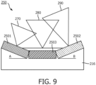
- Figs. 7, 8 and 9 are diagrammatic side views of transducer element 250 of rotational IVUS imaging system 200 with various transducer arrangements, according to aspects of the present disclosure.
- the transducer element 250 includes a first ultrasound transducer 2501 operating at a first center frequency, a second ultrasound transducer 2502 operating at a second center frequency, and a third ultrasound transducer 2503 operating at a third center frequency.
- the first, second and third ultrasound transducers 2501, 2502 and 2503 are disposed linearly parallel to a longitudinal axis of the transducer element 250.
- the first, second and third ultrasound transducers 2501, 2502 and 2503 are disposed linearly parallel to the longitudinal axis of the flexible elongate member 212.
- the first, second and third center frequencies are different from one another.
- the first center frequency is higher than the second center frequency
- the second center frequency is higher than the third center frequency.
- the first ultrasound transducer 2501 has highest spatial resolution and a smallest depth of penetration of the three ultrasound transducers.
- the third ultrasound transducer 2503 has the smallest spatial resolution and a greatest depth of penetration of the three, while the second ultrasound transducer 2502 has mid pack spatial resolution and depth of penetration.
- the first ultrasound transducer 2501 has a field of view 270
- the second ultrasound transducer 2502 has a field of view 280
- the third ultrasound transducer 2503 has a field of view 290.
- Fig. 8 shows an arrangement of ultrasound transducers 2501, 2502 and 2503 different from what is shown in Fig. 7 .
- the first ultrasound transducer 2501 does not lay flat in the transducer assembly 216 but is tilted at an angle A. It is noted that the first ultrasound transducer 2501 can be tilted distally or proximally. In some instances, the tilted first ultrasound transducer 2501 operates at the highest center frequency. In some implementations, the second center frequency is higher than the third center frequency.
- the first ultrasound transducer 2501 has a field of view 270
- the second ultrasound transducer 2502 has a field of view 280
- the third ultrasound transducer 2503 has a field of view 290.
- the IVUS console or processing system 206 can be configured to acquire Doppler ultrasound data from a blood vessel from the first ultrasound transducer 2501, and can analyze the data to determine the presence or absence, the direction, and the amount of fluid flow.
- Doppler ultrasound measures the movement of objects through the emitted beam as a phase change in the received signal.
- a moving structure e.g., a red blood cell within a blood vessel
- the wavelength and the frequency of the returning waves are shifted. If the moving structure is moving toward the first ultrasound transducer 2501, the frequency increases. If the moving structure is moving away from the first ultrasound transducer 2501, the frequency decreases.
- Fig. 9 shows an arrangement of ultrasound transducers 2501, 2502 and 2503 different from what is shown in Figs. 7 and 8 .
- both the first ultrasound transducer 2501 and the second ultrasound transducer 2502 do not lay flat in the transducer assembly 216 but are tilted at angles A and B, respectively.
- the first and second ultrasound transducers 2501 and 2502 are tilted towards the center. That is, one of the first and second ultrasound transducers 2501 and 2502 is tilted distally while the other is tilted proximally.
- the third ultrasound transducer 2503 has a lowest center frequency is disposed between the first and second ultrasound transducers 2501 and 2502 along the longitudinal axis of the flexible elongate member 212.
- the first ultrasound transducer 2501 has a field of view 270
- the second ultrasound transducer 2502 has a field of view 280
- the third ultrasound transducer 2503 has a field of view 290.
- the fields of view 270, 280, and 290 can be overlapping in some instances.
- a computing device can generate a single IVUS image of a single location of the vessel using data from multiple transducers (with different center frequencies).
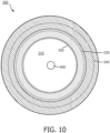
- Fig. 10 is a cross-section view of a vessel 300 of a patient, according to aspects of the present disclosure.
- Vessel 300 includes several layers.
- vessel 300 includes tunica intima 330 and tunica media 340.
- Tunica intima 330 has an internal vessel wall 320, which defines a lumen 310.
- an IVUS device 400 such as IVUS device 102 or catheter 202, is positioned with the lumen 310, it is advantageous if the IVUS device 400 is capable of obtaining ultrasound imaging data of differing depth of penetration to resolve features in tunica intima 330, the tunica media 340, and velocity of blood flowing in lumen 310.
- the present disclosure provides IVUS imaging systems that include multiple ultrasound transducers operating at different center frequencies. With use of IVUS imaging systems disclosed in the present disclosure, a physician performing catheterization can obtain not only grayscale ultrasound images but also color-Doppler images without having to insert different purpose-built IVUS catheters into a patient's vessel.
Landscapes
- Health & Medical Sciences (AREA)
- Life Sciences & Earth Sciences (AREA)
- Engineering & Computer Science (AREA)
- Medical Informatics (AREA)
- Surgery (AREA)
- Pathology (AREA)
- Radiology & Medical Imaging (AREA)
- Biophysics (AREA)
- Biomedical Technology (AREA)
- Heart & Thoracic Surgery (AREA)
- Physics & Mathematics (AREA)
- Molecular Biology (AREA)
- Nuclear Medicine, Radiotherapy & Molecular Imaging (AREA)
- Animal Behavior & Ethology (AREA)
- General Health & Medical Sciences (AREA)
- Public Health (AREA)
- Veterinary Medicine (AREA)
- Vascular Medicine (AREA)
- Gynecology & Obstetrics (AREA)
- Computer Vision & Pattern Recognition (AREA)
- Hematology (AREA)
- Ultra Sonic Daignosis Equipment (AREA)
Applications Claiming Priority (2)
| Application Number | Priority Date | Filing Date | Title |
|---|---|---|---|
| US201762538640P | 2017-07-28 | 2017-07-28 | |
| PCT/EP2018/070498 WO2019020817A1 (en) | 2017-07-28 | 2018-07-27 | INTRALUMINAL IMAGING DEVICES WITH MULTIPLE CENTRAL FREQUENCIES |
Publications (2)
| Publication Number | Publication Date |
|---|---|
| EP3658037A1 EP3658037A1 (en) | 2020-06-03 |
| EP3658037B1 true EP3658037B1 (en) | 2023-10-11 |
Family
ID=63311977
Family Applications (1)
| Application Number | Title | Priority Date | Filing Date |
|---|---|---|---|
| EP18758812.4A Active EP3658037B1 (en) | 2017-07-28 | 2018-07-27 | Intraluminal imaging devices with multiple center frequencies |
Country Status (5)
| Country | Link |
|---|---|
| US (1) | US11576652B2 (ja) |
| EP (1) | EP3658037B1 (ja) |
| JP (1) | JP7199415B2 (ja) |
| CN (1) | CN110958858B (ja) |
| WO (1) | WO2019020817A1 (ja) |
Cited By (1)
| Publication number | Priority date | Publication date | Assignee | Title |
|---|---|---|---|---|
| US11980778B2 (en) | 2018-11-28 | 2024-05-14 | Histosonics, Inc. | Histotripsy systems and methods |
Families Citing this family (6)
| Publication number | Priority date | Publication date | Assignee | Title |
|---|---|---|---|---|
| WO2021155026A1 (en) | 2020-01-28 | 2021-08-05 | The Regents Of The University Of Michigan | Systems and methods for histotripsy immunosensitization |
| US20220032010A1 (en) * | 2020-07-31 | 2022-02-03 | Avent, Inc. | Airway Detection Using Ultrasound |
| US20220117584A1 (en) * | 2020-10-20 | 2022-04-21 | GE Precision Healthcare LLC | System And Method Of Signal Processing For Ultrasound Arrays With Mechanically Adjustable Transducer Shapes |
| CN114145713A (zh) * | 2021-11-30 | 2022-03-08 | 深圳先进技术研究院 | 一种双频内窥导管及成像装置 |
| CN116035621B (zh) * | 2023-03-02 | 2023-06-16 | 深圳微创踪影医疗装备有限公司 | 血管内超声成像方法、装置、计算机设备、存储介质 |
| CN116363038A (zh) * | 2023-06-02 | 2023-06-30 | 深圳英美达医疗技术有限公司 | 超声图像融合方法、装置、计算机设备及存储介质 |
Family Cites Families (14)
| Publication number | Priority date | Publication date | Assignee | Title |
|---|---|---|---|---|
| US7226417B1 (en) | 1995-12-26 | 2007-06-05 | Volcano Corporation | High resolution intravascular ultrasound transducer assembly having a flexible substrate |
| CN1119974C (zh) | 1999-12-30 | 2003-09-03 | 复旦大学 | 双超声束多普勒血流速度测量方法 |
| CA2429940C (en) | 2000-12-01 | 2008-07-08 | The Cleveland Clinic Foundation | Miniature ultrasound transducer |
| JP4590293B2 (ja) | 2005-04-11 | 2010-12-01 | 富士フイルム株式会社 | 超音波観測装置 |
| US20060253028A1 (en) * | 2005-04-20 | 2006-11-09 | Scimed Life Systems, Inc. | Multiple transducer configurations for medical ultrasound imaging |
| EP2525717A1 (en) * | 2010-01-19 | 2012-11-28 | Koninklijke Philips Electronics N.V. | Imaging apparatus |
| US8591421B2 (en) * | 2010-11-12 | 2013-11-26 | Boston Scientific Scimed, Inc. | Systems and methods for making and using rotational transducers for concurrently imaging blood flow and tissue |
| US10869648B2 (en) * | 2012-05-11 | 2020-12-22 | Philips Image Guided Therapy Corporation | Device, system and method for flow imaging in the body using a swept transducer |
| WO2013181194A1 (en) | 2012-06-01 | 2013-12-05 | North Carolina State University | Catheter device implementing high frequency, contrast imaging ultrasound transducer, and associated method |
| US20140236011A1 (en) | 2012-08-31 | 2014-08-21 | General Electric Company | Methods and systems for simultaneous interventional imaging and functional measurements |
| JP6129509B2 (ja) | 2012-10-04 | 2017-05-17 | 東芝メディカルシステムズ株式会社 | 超音波医療装置及び超音波画像診断装置 |
| US20140187964A1 (en) | 2012-12-28 | 2014-07-03 | Volcano Corporation | Intravascular Ultrasound Catheter for Minimizing Image Distortion |
| US20150305716A1 (en) * | 2014-04-28 | 2015-10-29 | Koninklijke Philips N.V | Ultrasound Transducer Array Apparatus and Method of Imaging Using Transducer Arrays |
| CN104605892B (zh) | 2015-01-21 | 2018-04-06 | 上海爱声生物医疗科技有限公司 | 具有双频率的单、多阵元ivus换能器及其成型方法 |
-
2018
- 2018-07-27 CN CN201880048925.XA patent/CN110958858B/zh active Active
- 2018-07-27 JP JP2020504021A patent/JP7199415B2/ja active Active
- 2018-07-27 EP EP18758812.4A patent/EP3658037B1/en active Active
- 2018-07-27 WO PCT/EP2018/070498 patent/WO2019020817A1/en unknown
- 2018-07-27 US US16/048,121 patent/US11576652B2/en active Active
Cited By (1)
| Publication number | Priority date | Publication date | Assignee | Title |
|---|---|---|---|---|
| US11980778B2 (en) | 2018-11-28 | 2024-05-14 | Histosonics, Inc. | Histotripsy systems and methods |
Also Published As
| Publication number | Publication date |
|---|---|
| JP7199415B2 (ja) | 2023-01-05 |
| CN110958858A (zh) | 2020-04-03 |
| EP3658037A1 (en) | 2020-06-03 |
| US11576652B2 (en) | 2023-02-14 |
| JP2020528322A (ja) | 2020-09-24 |
| US20190029642A1 (en) | 2019-01-31 |
| CN110958858B (zh) | 2023-05-05 |
| WO2019020817A1 (en) | 2019-01-31 |
Similar Documents
| Publication | Publication Date | Title |
|---|---|---|
| EP3658037B1 (en) | Intraluminal imaging devices with multiple center frequencies | |
| US20210059642A1 (en) | Intravascular ultrasound device with impedance matching structure | |
| US20150305716A1 (en) | Ultrasound Transducer Array Apparatus and Method of Imaging Using Transducer Arrays | |
| JP2015515918A (ja) | 撮像及び血流測定のための超音波カテーテル | |
| CN1942144A (zh) | 具有宽视场特征的超声成像探头 | |
| US20230293149A1 (en) | Phased array intravascular devices, systems, and methods utilizing photoacoustic and ultrasound techniques` | |
| EP3697315B1 (en) | Digital rotational patient interface module | |
| US10646200B2 (en) | Intravascular ultrasound imaging system with slip ring interface and associated devices, systems, and methods | |
| JP2019217298A (ja) | 血管内超音波(ivus)デバイスのための相互接続 | |
| US20230190230A1 (en) | Systems, devices, and methods for reducing reverberation signals in intravascular ultrasound imaging | |
| US20230218266A1 (en) | Tissue and vascular pathway mapping using synchronized photoacoustic and ultrasound pullback techniques | |
| US20160015362A1 (en) | Intravascular devices, systems, and methods having motors | |
| JP7250134B2 (ja) | 超音波画像のためのグレーティングローブアーチファクト最小化、並びに関連する装置、システム、及び方法 | |
| EP3592243B1 (en) | Imaging assembly for intraluminal imaging | |
| WO2019110404A1 (en) | Flexible tip for intraluminal imaging device and associated devices, systems, and methods | |
| US20220287679A1 (en) | Disposable catheter with rotatable image array |
Legal Events
| Date | Code | Title | Description |
|---|---|---|---|
| STAA | Information on the status of an ep patent application or granted ep patent |
Free format text: STATUS: UNKNOWN |
|
| STAA | Information on the status of an ep patent application or granted ep patent |
Free format text: STATUS: THE INTERNATIONAL PUBLICATION HAS BEEN MADE |
|
| PUAI | Public reference made under article 153(3) epc to a published international application that has entered the european phase |
Free format text: ORIGINAL CODE: 0009012 |
|
| STAA | Information on the status of an ep patent application or granted ep patent |
Free format text: STATUS: REQUEST FOR EXAMINATION WAS MADE |
|
| 17P | Request for examination filed |
Effective date: 20200228 |
|
| AK | Designated contracting states |
Kind code of ref document: A1 Designated state(s): AL AT BE BG CH CY CZ DE DK EE ES FI FR GB GR HR HU IE IS IT LI LT LU LV MC MK MT NL NO PL PT RO RS SE SI SK SM TR |
|
| AX | Request for extension of the european patent |
Extension state: BA ME |
|
| DAV | Request for validation of the european patent (deleted) | ||
| DAX | Request for extension of the european patent (deleted) | ||
| STAA | Information on the status of an ep patent application or granted ep patent |
Free format text: STATUS: EXAMINATION IS IN PROGRESS |
|
| 17Q | First examination report despatched |
Effective date: 20211013 |
|
| GRAP | Despatch of communication of intention to grant a patent |
Free format text: ORIGINAL CODE: EPIDOSNIGR1 |
|
| STAA | Information on the status of an ep patent application or granted ep patent |
Free format text: STATUS: GRANT OF PATENT IS INTENDED |
|
| INTG | Intention to grant announced |
Effective date: 20230523 |
|
| GRAS | Grant fee paid |
Free format text: ORIGINAL CODE: EPIDOSNIGR3 |
|
| GRAA | (expected) grant |
Free format text: ORIGINAL CODE: 0009210 |
|
| STAA | Information on the status of an ep patent application or granted ep patent |
Free format text: STATUS: THE PATENT HAS BEEN GRANTED |
|
| AK | Designated contracting states |
Kind code of ref document: B1 Designated state(s): AL AT BE BG CH CY CZ DE DK EE ES FI FR GB GR HR HU IE IS IT LI LT LU LV MC MK MT NL NO PL PT RO RS SE SI SK SM TR |
|
| REG | Reference to a national code |
Ref country code: GB Ref legal event code: FG4D |
|
| REG | Reference to a national code |
Ref country code: CH Ref legal event code: EP |
|
| REG | Reference to a national code |
Ref country code: DE Ref legal event code: R096 Ref document number: 602018059186 Country of ref document: DE |
|
| REG | Reference to a national code |
Ref country code: IE Ref legal event code: FG4D |
|
| REG | Reference to a national code |
Ref country code: LT Ref legal event code: MG9D |
|
| REG | Reference to a national code |
Ref country code: NL Ref legal event code: MP Effective date: 20231011 |
|
| REG | Reference to a national code |
Ref country code: AT Ref legal event code: MK05 Ref document number: 1619408 Country of ref document: AT Kind code of ref document: T Effective date: 20231011 |
|
| PG25 | Lapsed in a contracting state [announced via postgrant information from national office to epo] |
Ref country code: NL Free format text: LAPSE BECAUSE OF FAILURE TO SUBMIT A TRANSLATION OF THE DESCRIPTION OR TO PAY THE FEE WITHIN THE PRESCRIBED TIME-LIMIT Effective date: 20231011 |
|
| PG25 | Lapsed in a contracting state [announced via postgrant information from national office to epo] |
Ref country code: GR Free format text: LAPSE BECAUSE OF FAILURE TO SUBMIT A TRANSLATION OF THE DESCRIPTION OR TO PAY THE FEE WITHIN THE PRESCRIBED TIME-LIMIT Effective date: 20240112 |
|
| PG25 | Lapsed in a contracting state [announced via postgrant information from national office to epo] |
Ref country code: IS Free format text: LAPSE BECAUSE OF FAILURE TO SUBMIT A TRANSLATION OF THE DESCRIPTION OR TO PAY THE FEE WITHIN THE PRESCRIBED TIME-LIMIT Effective date: 20240211 |
|
| PG25 | Lapsed in a contracting state [announced via postgrant information from national office to epo] |
Ref country code: LT Free format text: LAPSE BECAUSE OF FAILURE TO SUBMIT A TRANSLATION OF THE DESCRIPTION OR TO PAY THE FEE WITHIN THE PRESCRIBED TIME-LIMIT Effective date: 20231011 |
|
| PG25 | Lapsed in a contracting state [announced via postgrant information from national office to epo] |
Ref country code: AT Free format text: LAPSE BECAUSE OF FAILURE TO SUBMIT A TRANSLATION OF THE DESCRIPTION OR TO PAY THE FEE WITHIN THE PRESCRIBED TIME-LIMIT Effective date: 20231011 |
|
| PG25 | Lapsed in a contracting state [announced via postgrant information from national office to epo] |
Ref country code: ES Free format text: LAPSE BECAUSE OF FAILURE TO SUBMIT A TRANSLATION OF THE DESCRIPTION OR TO PAY THE FEE WITHIN THE PRESCRIBED TIME-LIMIT Effective date: 20231011 |
|
| PG25 | Lapsed in a contracting state [announced via postgrant information from national office to epo] |
Ref country code: LT Free format text: LAPSE BECAUSE OF FAILURE TO SUBMIT A TRANSLATION OF THE DESCRIPTION OR TO PAY THE FEE WITHIN THE PRESCRIBED TIME-LIMIT Effective date: 20231011 Ref country code: IS Free format text: LAPSE BECAUSE OF FAILURE TO SUBMIT A TRANSLATION OF THE DESCRIPTION OR TO PAY THE FEE WITHIN THE PRESCRIBED TIME-LIMIT Effective date: 20240211 Ref country code: GR Free format text: LAPSE BECAUSE OF FAILURE TO SUBMIT A TRANSLATION OF THE DESCRIPTION OR TO PAY THE FEE WITHIN THE PRESCRIBED TIME-LIMIT Effective date: 20240112 Ref country code: ES Free format text: LAPSE BECAUSE OF FAILURE TO SUBMIT A TRANSLATION OF THE DESCRIPTION OR TO PAY THE FEE WITHIN THE PRESCRIBED TIME-LIMIT Effective date: 20231011 Ref country code: BG Free format text: LAPSE BECAUSE OF FAILURE TO SUBMIT A TRANSLATION OF THE DESCRIPTION OR TO PAY THE FEE WITHIN THE PRESCRIBED TIME-LIMIT Effective date: 20240111 Ref country code: AT Free format text: LAPSE BECAUSE OF FAILURE TO SUBMIT A TRANSLATION OF THE DESCRIPTION OR TO PAY THE FEE WITHIN THE PRESCRIBED TIME-LIMIT Effective date: 20231011 Ref country code: PT Free format text: LAPSE BECAUSE OF FAILURE TO SUBMIT A TRANSLATION OF THE DESCRIPTION OR TO PAY THE FEE WITHIN THE PRESCRIBED TIME-LIMIT Effective date: 20240212 |