EP3633281B1 - Central air-conditioning temperature control device, fan coil control method, medium and system - Google Patents
Central air-conditioning temperature control device, fan coil control method, medium and system Download PDFInfo
- Publication number
- EP3633281B1 EP3633281B1 EP18810374.1A EP18810374A EP3633281B1 EP 3633281 B1 EP3633281 B1 EP 3633281B1 EP 18810374 A EP18810374 A EP 18810374A EP 3633281 B1 EP3633281 B1 EP 3633281B1
- Authority
- EP
- European Patent Office
- Prior art keywords
- temperature
- control apparatus
- temperature control
- ambient temperature
- configuring
- Prior art date
- Legal status (The legal status is an assumption and is not a legal conclusion. Google has not performed a legal analysis and makes no representation as to the accuracy of the status listed.)
- Active
Links
- 238000000034 method Methods 0.000 title claims description 46
- 238000004378 air conditioning Methods 0.000 title description 2
- 230000008859 change Effects 0.000 claims description 61
- 238000001816 cooling Methods 0.000 claims description 36
- 238000010438 heat treatment Methods 0.000 claims description 36
- 230000004044 response Effects 0.000 claims description 23
- 230000003247 decreasing effect Effects 0.000 claims description 21
- 238000009423 ventilation Methods 0.000 claims description 21
- 238000013507 mapping Methods 0.000 claims description 5
- 230000009471 action Effects 0.000 claims description 4
- 238000004458 analytical method Methods 0.000 claims description 3
- 238000004891 communication Methods 0.000 description 13
- 230000000875 corresponding effect Effects 0.000 description 12
- 230000006870 function Effects 0.000 description 12
- 230000008569 process Effects 0.000 description 12
- 238000012795 verification Methods 0.000 description 12
- 230000001276 controlling effect Effects 0.000 description 8
- 238000007726 management method Methods 0.000 description 8
- 238000013475 authorization Methods 0.000 description 7
- 238000010586 diagram Methods 0.000 description 6
- QVFWZNCVPCJQOP-UHFFFAOYSA-N chloralodol Chemical compound CC(O)(C)CC(C)OC(O)C(Cl)(Cl)Cl QVFWZNCVPCJQOP-UHFFFAOYSA-N 0.000 description 5
- 238000012546 transfer Methods 0.000 description 5
- 230000000694 effects Effects 0.000 description 4
- 230000006855 networking Effects 0.000 description 4
- XLYOFNOQVPJJNP-UHFFFAOYSA-N water Substances O XLYOFNOQVPJJNP-UHFFFAOYSA-N 0.000 description 4
- 230000008878 coupling Effects 0.000 description 3
- 238000010168 coupling process Methods 0.000 description 3
- 238000005859 coupling reaction Methods 0.000 description 3
- 230000002354 daily effect Effects 0.000 description 3
- 238000005265 energy consumption Methods 0.000 description 3
- 238000012986 modification Methods 0.000 description 3
- 230000004048 modification Effects 0.000 description 3
- 238000012544 monitoring process Methods 0.000 description 3
- 238000013500 data storage Methods 0.000 description 2
- 238000005516 engineering process Methods 0.000 description 2
- 239000004973 liquid crystal related substance Substances 0.000 description 2
- 238000005070 sampling Methods 0.000 description 2
- 238000006467 substitution reaction Methods 0.000 description 2
- 230000009286 beneficial effect Effects 0.000 description 1
- 230000005540 biological transmission Effects 0.000 description 1
- 238000006243 chemical reaction Methods 0.000 description 1
- 239000007795 chemical reaction product Substances 0.000 description 1
- 238000004590 computer program Methods 0.000 description 1
- 238000007405 data analysis Methods 0.000 description 1
- 238000012217 deletion Methods 0.000 description 1
- 230000037430 deletion Effects 0.000 description 1
- 230000001419 dependent effect Effects 0.000 description 1
- 230000003203 everyday effect Effects 0.000 description 1
- 238000009434 installation Methods 0.000 description 1
- 238000012545 processing Methods 0.000 description 1
- 238000003672 processing method Methods 0.000 description 1
- 230000003442 weekly effect Effects 0.000 description 1
Images


Classifications
-
- F—MECHANICAL ENGINEERING; LIGHTING; HEATING; WEAPONS; BLASTING
- F24—HEATING; RANGES; VENTILATING
- F24F—AIR-CONDITIONING; AIR-HUMIDIFICATION; VENTILATION; USE OF AIR CURRENTS FOR SCREENING
- F24F11/00—Control or safety arrangements
- F24F11/30—Control or safety arrangements for purposes related to the operation of the system, e.g. for safety or monitoring
-
- F—MECHANICAL ENGINEERING; LIGHTING; HEATING; WEAPONS; BLASTING
- F24—HEATING; RANGES; VENTILATING
- F24F—AIR-CONDITIONING; AIR-HUMIDIFICATION; VENTILATION; USE OF AIR CURRENTS FOR SCREENING
- F24F11/00—Control or safety arrangements
- F24F11/50—Control or safety arrangements characterised by user interfaces or communication
- F24F11/56—Remote control
- F24F11/58—Remote control using Internet communication
-
- F—MECHANICAL ENGINEERING; LIGHTING; HEATING; WEAPONS; BLASTING
- F24—HEATING; RANGES; VENTILATING
- F24F—AIR-CONDITIONING; AIR-HUMIDIFICATION; VENTILATION; USE OF AIR CURRENTS FOR SCREENING
- F24F11/00—Control or safety arrangements
- F24F11/62—Control or safety arrangements characterised by the type of control or by internal processing, e.g. using fuzzy logic, adaptive control or estimation of values
- F24F11/63—Electronic processing
- F24F11/64—Electronic processing using pre-stored data
-
- F—MECHANICAL ENGINEERING; LIGHTING; HEATING; WEAPONS; BLASTING
- F24—HEATING; RANGES; VENTILATING
- F24F—AIR-CONDITIONING; AIR-HUMIDIFICATION; VENTILATION; USE OF AIR CURRENTS FOR SCREENING
- F24F11/00—Control or safety arrangements
- F24F11/62—Control or safety arrangements characterised by the type of control or by internal processing, e.g. using fuzzy logic, adaptive control or estimation of values
- F24F11/63—Electronic processing
- F24F11/65—Electronic processing for selecting an operating mode
- F24F11/67—Switching between heating and cooling modes
-
- F—MECHANICAL ENGINEERING; LIGHTING; HEATING; WEAPONS; BLASTING
- F24—HEATING; RANGES; VENTILATING
- F24F—AIR-CONDITIONING; AIR-HUMIDIFICATION; VENTILATION; USE OF AIR CURRENTS FOR SCREENING
- F24F11/00—Control or safety arrangements
- F24F11/70—Control systems characterised by their outputs; Constructional details thereof
- F24F11/72—Control systems characterised by their outputs; Constructional details thereof for controlling the supply of treated air, e.g. its pressure
- F24F11/74—Control systems characterised by their outputs; Constructional details thereof for controlling the supply of treated air, e.g. its pressure for controlling air flow rate or air velocity
- F24F11/77—Control systems characterised by their outputs; Constructional details thereof for controlling the supply of treated air, e.g. its pressure for controlling air flow rate or air velocity by controlling the speed of ventilators
-
- F—MECHANICAL ENGINEERING; LIGHTING; HEATING; WEAPONS; BLASTING
- F24—HEATING; RANGES; VENTILATING
- F24F—AIR-CONDITIONING; AIR-HUMIDIFICATION; VENTILATION; USE OF AIR CURRENTS FOR SCREENING
- F24F11/00—Control or safety arrangements
- F24F11/70—Control systems characterised by their outputs; Constructional details thereof
- F24F11/80—Control systems characterised by their outputs; Constructional details thereof for controlling the temperature of the supplied air
-
- F—MECHANICAL ENGINEERING; LIGHTING; HEATING; WEAPONS; BLASTING
- F24—HEATING; RANGES; VENTILATING
- F24F—AIR-CONDITIONING; AIR-HUMIDIFICATION; VENTILATION; USE OF AIR CURRENTS FOR SCREENING
- F24F2110/00—Control inputs relating to air properties
- F24F2110/10—Temperature
-
- F—MECHANICAL ENGINEERING; LIGHTING; HEATING; WEAPONS; BLASTING
- F24—HEATING; RANGES; VENTILATING
- F24F—AIR-CONDITIONING; AIR-HUMIDIFICATION; VENTILATION; USE OF AIR CURRENTS FOR SCREENING
- F24F2120/00—Control inputs relating to users or occupants
-
- Y—GENERAL TAGGING OF NEW TECHNOLOGICAL DEVELOPMENTS; GENERAL TAGGING OF CROSS-SECTIONAL TECHNOLOGIES SPANNING OVER SEVERAL SECTIONS OF THE IPC; TECHNICAL SUBJECTS COVERED BY FORMER USPC CROSS-REFERENCE ART COLLECTIONS [XRACs] AND DIGESTS
- Y02—TECHNOLOGIES OR APPLICATIONS FOR MITIGATION OR ADAPTATION AGAINST CLIMATE CHANGE
- Y02B—CLIMATE CHANGE MITIGATION TECHNOLOGIES RELATED TO BUILDINGS, e.g. HOUSING, HOUSE APPLIANCES OR RELATED END-USER APPLICATIONS
- Y02B30/00—Energy efficient heating, ventilation or air conditioning [HVAC]
- Y02B30/70—Efficient control or regulation technologies, e.g. for control of refrigerant flow, motor or heating
Definitions
- the present invention relates to the technical field of central air conditioners, in particular, to a central air conditioning temperature control apparatus, a method for controlling a fan coil and a computer-readable storage medium therefor.
- a fan coil of a central air conditioner is a most common end product of the central air conditioner, and consists of a heat exchanger, a water pipe, a filter, a fan, a water tray, a vent valve, a bracket, etc.
- the working principle of the fan coil is that the air in the room or outside is continuously recirculated in the unit, so that the air is cooled (heated) after passing through the cold water (hot water) coil to keep the temperature of the room constant.
- a temperature controller panel with a single chip microcomputer is installed on the wall near the fan opening, and the temperature controller panel has several buttons such as a switch, wind speed gears, and temperature addition and subtraction buttons and a liquid crystal screen displaying temperature.
- buttons such as a switch, wind speed gears, and temperature addition and subtraction buttons and a liquid crystal screen displaying temperature.
- a user controls the running of the fan coil by manual operation.
- the apparatus can control the coordination and fan coil unit.
- the coordination and the fan coil control device of the present invention comprise the sensor unit detecting the indoor temperature of the specified zone and the control unit which together controls the first coordination means reaching the indoor temperature to the preset temperature in the driving for the first period and the second coordination means reaching the indoor temperature to the preset temperature in the driving for the second time.
- Embodiments of the present invention provide a temperature control apparatus of a central air conditioner according to claim 11, a method for controlling a fan coil according to claim 1, and a computer-readable storage medium according to claim 13. Preferred embodiments of the invention are provided in the dependent claims.
- Embodiments of the present invention have the following beneficial effects.
- the running state of the temperature control apparatus is configured through the control terminal, or the running state of the temperature control apparatus is automatically configured, so the problems that the existing temperature controller needs to be manually configured and that the configuration process is troublesome are effectively solved.
- the present invention provides a temperature control apparatus of a central air conditioner, a method for controlling a fan coil and a medium, and the present invention will be further described below with reference to the drawings and embodiments. It is to be understood that the embodiments described herein are intended to explain and not to limit the present invention.
- an embodiment of the present invention provides a temperature control apparatus of a central air conditioner, and the temperature control apparatus includes a temperature collection module, a storage and a processor.
- the temperature collection module is configured to collect ambient temperature according to a set period.
- the storage is configured to store a fan coil control program
- the processor is configured to execute the fan coil control program to implement the following steps.
- a configuration instruction is received via a network, and a running state of the temperature control apparatus is configured according to the configuration instruction.
- a change trend of the ambient temperature is determined according to the collected ambient temperature; and the running state of the temperature control apparatus is configured according to the change trend of the ambient temperature.
- a corresponding control signal is sent to a fan coil connected with the temperature control apparatus according to the configured running state so as to enable the fan coil to start an action corresponding to the running state.
- the temperature collection module may be a temperature sensor, and the storage may be externally configured.
- the control terminal may employ any known terminal, such as a mobile phone and other mobile terminals.
- a wireless network may be adopted.
- the running state includes a cooling state, a heating state, and a ventilation state.
- the corresponding action of the running state may be opening or closing a solenoid valve of the fan coil, turning on or turning off a fan of the fan coil, or configuring a working speed of the fan.
- the configuration instruction may include a cooling command, a heating command, a ventilation command, and the like.
- the configuration instruction may further include: a switch-on instruction, a switch-off instruction, a timing instruction (including timing switch-on and timing switch-off), an entering-automatic-mode instruction, and an exiting- -automatic-mode instruction.
- the temperature control apparatus may be a temperature controller terminal (also referred to as a temperature controller) or a temperature controller gateway.
- the non-automatic working mode indicates that for the temperature controller, the running state of the temperature controller needs to be configured by a user through the control terminal.
- the automatic working mode indicates that for the temperature controller, the running state of the temperature controller does not need to be configured by the user through the control terminal, and the temperature controller may configure the running state of the temperature controller itself according to the change trend of the ambient temperature.
- the running state of the temperature control apparatus is configured through the control terminal, or the running state of the temperature control apparatus is automatically configured according to the change trend of the ambient temperature, so the problem that the existing temperature controller needs manual configuration is effectively solved and the control convenience of the existing temperature controller is improved.
- the step of determining a change trend of the ambient temperature according to the collected ambient temperature includes the following steps.
- the change trend of the ambient temperature is determined according to the ambient temperature of the each period node.
- the step of configuring the running state of the temperature control apparatus according to the change trend of the ambient temperature includes the following steps.
- the running state of the temperature control apparatus is configured to the cooling state, and a target cooling temperature is configured.
- the running state of the temperature control apparatus is configured to the heating state, and a target heating temperature is configured.
- the running state of the temperature control apparatus is configured to the ventilation state.
- the determining manner of the change trend of the ambient temperature includes the following manners.
- the change trend of the ambient temperature is the decreasing trend.
- the change trend of the ambient temperature is the increasing trend.
- the change trend of the ambient temperature is the flat trend.
- One determining period may be comprised of two adjacent period nodes, or may be comprised of two or more adjacent period nodes.
- temperature collection uses a manner of sampling for multiple times to determine the running of the temperature controller. If the number of rises of the sampled temperature at the time of switch-on is greater than the number of drops of the sampled temperature, it is considered to be the hot wind, and the jitter data caused by external factors is discarded (a similar strategy is used for determining the cold wind).
- N determining periods, if the number of decreasing trends of the change trend of the ambient temperature is determined to be larger, the change trend of the ambient temperature is finally determined to be a decreasing trend; and if the number of increasing trends of the change trend of the ambient temperature is determined to be larger, the change trend of the ambient temperature is finally determined to be an increasing trend; where N is an odd number.
- the working speed of the fan of the fan coil is configured to be a low speed; where the working speed includes a low speed (i.e., a first preset rate), a medium speed (i.e., a second preset rate), and a high speed (i.e., a third preset rate).
- a low speed i.e., a first preset rate
- a medium speed i.e., a second preset rate
- a high speed i.e., a third preset rate
- a working speed of a fan of the fan coil is configured according to a difference, where in the decreasing trend, the difference is a difference between currently acquired ambient temperature and the target cooling temperature, and in the increasing trend, the difference is a difference between the target heating temperature and the currently acquired ambient temperature.
- a temperature threshold T2 is less than a temperature threshold T1.
- the step of configuring a working speed of a fan of the fan coil according to a difference includes the following steps.
- the working speed of the fan is configured to be the high speed.
- the working speed of the fan is configured to be the low speed.
- the working speed of the fan is configured to be the medium speed, where T2 is greater than 0.
- the method may further include: when the difference is equal to 0, a solenoid valve of the fan coil is configured to be in a closed state; when the difference is less than a preset temperature threshold T3 (i.e., a third temperature threshold), the fan is configured to be in a closed state, where the temperature threshold T3 is less than 0.
- a preset temperature threshold T3 i.e., a third temperature threshold
- the method further includes: in preset time, when the difference is greater than the preset temperature threshold T4 (i.e., a fourth temperature threshold), the solenoid valve and the fan are configured to be in a switch-on state, where the temperature threshold T4 is greater than 0.
- T4 preset temperature threshold
- the processor executes the temperature control computer program and further implements the following steps.
- Running data of the temperature control apparatus is determined, and the running data is sent to a preset server, so that the server generates an analysis chart.
- State data of the temperature control apparatus is sent to a control terminal that obtains control authority from the server.
- the temperature control apparatus further includes a network connection module, which is configured to form a network with the control terminal and/or the server in a wireless or wired manner and interact with the intelligent terminal and/or the server about a control instruction and/or state data.
- a network connection module which is configured to form a network with the control terminal and/or the server in a wireless or wired manner and interact with the intelligent terminal and/or the server about a control instruction and/or state data.
- the step of receiving a configuration instruction via a network and configuring a running state of the temperature control apparatus according to the configuration instruction includes the following steps.
- the configuration instruction is received via a network, and a temperature control apparatus identifier is parsed from the configuration instruction, where the configuration instruction is any one of: a control instruction directly sent by the control terminal to the temperature control apparatus or the control instruction of the control terminal forwarded by the server to the temperature control apparatus.
- the running state of the temperature control apparatus is configured according to the configuration instruction.
- the temperature control apparatus identifier is a network address of the temperature control apparatus.
- the method Before the step of receiving the configuration instruction via a network and parsing a temperature control apparatus identifier from the configuration instruction, the method further includes the following steps.
- Heartbeat data is reported to the server, so that when the control instruction of the control terminal is received, the server forwards the received control instruction of the control terminal to a corresponding temperature control apparatus according to a preset mapping table of hardware addresses and network addresses, where the heartbeat data carries a hardware address of the temperature control apparatus.
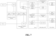
- an embodiment of the present invention provides a temperature controller system of a central air conditioner, and the system includes any temperature control apparatus described in the embodiment 1, a control terminal, and a server.
- the control terminal is configured to display and control the state of the temperature controller, for example, the control terminal is configured to obtain from the server a device list of temperature control apparatuses under control of the control terminal.
- the device list is displayed on a control interface.
- a temperature control apparatus selected by a user is received.
- a configuration instruction is sent to the selected temperature control apparatus.
- a control APP has been installed in the control terminal.
- the server is configured to manage authority of the temperature controller, display data statistics of the temperature control apparatus and forward a configuration instruction, and have communication data between the control APP and management software, where the management software is configured in the server.
- the temperature control apparatus is configured to control running of the fan coil and wirelessly communicate with the server module and the control terminal and automatically configure the mode, temperature, wind speed gear and switch of the temperature controller according to the ambient information.
- the temperature control apparatus may be any one of a temperature controller terminal or a temperature controller gateway.
- the temperature controller gateway is configured to control running of the fan coil and communicate with the server module and the temperature controller terminal module, and periodically report the heartbeat to the server module;
- the temperature controller gateway hardware mainly includes a network connection module, a processor, a real-time clock (RTC) clock, a temperature collection module (such as a temperature sensor), a light emitting diode (LED) indicator, a buzzer, a button, an external storage, a power supply module, and an liquid crystal display (LCD) touch screen.
- RTC real-time clock
- LED light emitting diode
- the network connection module is connected to the Internet and is responsible for communicating with the server on the Internet.
- the network connection module includes at least one wireless network module, and the network connection module may further include a wireless network module or a wired network module, where the wireless network module is preferably a WiFi network processor.
- the network connection module is responsible for receiving the configuration instruction of the temperature controller forwarded by the network processor and forwarding the configuration instruction to the temperature controller gateway.
- the wired network module and the wireless network module transfer data to each other through the processor, and convert the data through a customized protocol. If the wireless network module has the function of connecting to the Internet, the network processor for connecting to the Internet may be removed from the gateway device hardware.
- the wireless network module may be configured with a power amplifier configured to amplify the wireless signal of the wireless network module, so that the wireless signal is transmitted farther; certainly, the power amplifier may also be configured in the wired network module.
- a processor is configured to control the signal lines of the fan coil and to connect the various hardware modules.
- the RTC clock module is configured to perform timing and obtain server time in real time for time check.
- the temperature collection module is configured to collect ambient temperature.
- the LED indicator is configured to indicate the running state of the temperature controller and the network state.
- the buzzer is configured for device identification during networking.
- the external storage is configured to store the fan coil control program, the running version files of each chip and some key data of the temperature controller during running.
- the button is mainly configured to have functions of configuring a state of the temperature controller, resetting the device, and restoring the factory configurations.
- the power supply module is configured to power the device.
- the LCD touch screen is an optional module, and is configured to display the state of the temperature controller and configure the temperature controller. If the user requires the usage habits of the conventional temperature controller panel to be compatible, the LCD touch screen is configured; if the user is more accustomed to using the control terminal for remote operation, the LCD touch screen is not configured.
- the temperature controller gateway itself is also a temperature controller. Compared with the temperature controller terminal, one more network processor exists, and the performance configurations of the wireless network module and the performance configurations of other hardware are stronger than those of the terminal device. According to the needs of the user, the gateway may be independent, and the function of the temperature controller is not integrated. Each temperature controller system requires at least one gateway device or multiple gateway devices may be deployed.
- the hardware of the temperature controller terminal device mainly includes a wireless network module, a processor, an RTC clock, a temperature collection module, an LED indicator, a buzzer, an external storage, a button, a power supply module, an LCD touch screen, and may also include a timing switch module, a lock and unlock module, a statistics module, and a reporting module.
- the wireless network module has a Mesh (wireless grid network) network function
- the wireless network module is configured to communicate with the wireless network module of the gateway device or the wireless network module of the next hop.
- Other components have the same function as a gateway component.
- Each temperature controller system has zero, one or multiple terminal devices. The temperature controller is installed in the range of about 1 meter from the fan coil outlet to save wiring.
- the timing switch function is configured by the user in the APP of the control terminal (such as a mobile phone).
- the software module of the temperature controller terminal stores the configurations, and after the time point configured by the user is reached, the switch-on and switch-off configurations are automatically performed on the temperature controller.
- An example of the main interface and an example of the configuration interface of the APP are shown in FIG. 4 and FIG. 5 respectively.
- the wireless network module is mainly responsible for wireless communication and data forwarding.
- the wireless network module includes network processor software and a network processor, and is mainly responsible for performing protocol conversion between the wireless network module and the network processor, reporting the heartbeat to the server, collecting the online state of each temperature controller terminal and ambient temperature, and other functions.
- the temperature collection module starts to periodically collect the ambient temperature data.
- the temperature controller terminal automatically configures the running state, temperature, and gear of the temperature controller by determining the change of the ambient temperature.
- temperature collection uses a manner of sampling for multiple times to determine the running of the temperature controller terminal. If the number of rises of the sampled temperature at the time of switch-on is greater than the number of drops of the sampled temperature, it is considered to be the hot wind, and the jitter data caused by external factors is discarded (a similar strategy is used for determining the cold wind).
- the temperature controller terminal is automatically configured to be a default cooling temperature. If the ambient temperature is lower than the default cooling temperature, the solenoid valve is closed and fan of the fan coil is turned off. If the ambient temperature is higher than the default cooling temperature, the gear of the fan is configured according to the magnitude of difference between the ambient temperature and the configured temperature.
- the temperature of the temperature controller is automatically configured to be a default heating temperature. If the ambient temperature is higher than the default heating temperature, the solenoid valve is closed and the fan of the fan coil is turned off. If the ambient temperature is lower than the default heating temperature, the gear of the fan is configured according to the magnitude of difference between the ambient temperature and the configured temperature.
- the default cooling temperature of the system is 26°C
- the default heating temperature of the system is 20°C
- these values are also the government's recommended value for temperature configuration in the office area.
- the default configuration temperature may effectively reduce energy consumption of the central air conditioner, and in special cases, the user may configure other temperature values. After the user configures other temperature, the temperature for closing the solenoid valve of the fan coil and turning off the fan is automatically adjusted accordingly.
- the temperature controller terminal runs according to the configurations of the user, and the automatic mode does not take effect.
- the automatic mode takes effect again after the user selects the automatic mode.
- the software module of the temperature controller terminal includes the following program modules.
- An anti-shake module is configured to screen the effective change information of the collected temperature.
- a first determining module is configured to determine the change trend, e.g., higher or unchanged, of the ambient temperature after the temperature controller is turned on.
- a temperature mode automatic configuration module is configured to configure the running mode to heating when the first determining module indicates an increasing trend and configure the default heating temperature; configure the running mode to be cooling when the first determining module indicates a decreasing trend and configure the default cooling temperature (i.e., the target temperature); and configure the running mode to be ventilation when the first determining module indicates that the temperature is unchanged.
- a second determining module is configured to determine the difference between the ambient temperature and the default temperature under the decreasing trend; and determine the difference between the default temperature and the ambient temperature under the increasing trend.
- a fan gear automatic configuration module is configured to configure the fan gear to be a low speed when the first determining result indicates that the temperature is unchanged.
- the fan gear automatic configuration module is further configured to configure the working speed of the fan to be the third preset rate if the difference is greater than the preset temperature threshold T1. If the difference is less than the preset temperature threshold T2 and not less than 0, the working speed of the fan is configured to be the first preset rate.
- the working speed of the fan is configured to be the second preset rate; where the first preset rate is lower than the second preset rate, and the second preset rate is lower than the third preset rate; and the temperature threshold T2 is less than the temperature threshold T1.
- a switch-on and switch-off automatic configuration module is configured to configure the solenoid valve of the fan coil to be in a closed state when the difference is equal to 0.
- the difference is less than a preset temperature threshold T3
- the fan is configured to be in a turn-off state; where the temperature threshold T3 is less than 0.
- the solenoid valve of the fan coil when the temperature mode automatic configuration module configures the mode to be cooling and the temperature difference determined by the second determining module is 0, the solenoid valve of the fan coil is configured to be closed, when the temperature difference of the second determining module is lower than the configuration temperature T3, the fan of the fan coil is configured to be turned off, and after a period of turn-off, when the temperature difference determined by the second determining module is higher than the configuration temperature T4, the fan is automatically turned on and the solenoid valve automatically opens; when the temperature mode automatic configuration module configures the mode to be heating and the temperature difference of the second determining module is 0, the solenoid valve of the fan coil is configured to be closed, when the temperature difference of the second determining module is lower than the configuration temperature T3, the fan of the fan coil is configured to be turned off, and after a period of turn-off, when the temperature difference of the second determining module is higher than the configuration temperature T4, the fan is automatically turned on and the solenoid valve automatically opens.
- the processor is configured to control the temperature controller and connect the hardware components of the temperature controller; and is configured to respond to the configuration instructions of various temperature, modes, gears and switches of the control terminal APP and control the running of the fan coil.
- the timing switch module is configured to automatically switch on or switch off after the timing switch-on/-off time configured by the user is up.
- the lock and unlock module is configured to, after the administrator locks the temperature controller, not allow other users to perform remote configuration on the temperature controller, and also not allow configuration of buttons on the LCD panel.
- the statistics module is configured to automatically count the daily running time of the temperature controller in various modes and gears, and obtain the running data of the temperature controller.
- the reporting module is configured to report the running data of the temperature controller terminal to the server.
- the server is mainly responsible for communication with the temperature controller terminal device, the temperature controller gateway device and the control terminal; the server is also responsible for the user's login authority management, user authorization management and user operation log statistics.
- the server is generally deployed on a cloud server or deployed on a server built by itself.
- the server includes a statistical data storage module, an operation log storage module, an authority management module, a statistical data charting module and an operation log query module.
- the statistical data storage module is configured to store statistical data of the temperature control apparatus in a database.
- the operation log storage module is configured to store the user's remote operation record in an operation log.
- the authority management module is configured to send information of the authorized devices to the control terminal when the control terminal requests a device list.
- the statistical data charting module is configured to plot data in the database into a chart on the management software.
- the operation log query module is configured for an administrator to query the above operation log.3.
- the control terminal displays the state of the temperature control apparatus, controls the temperature control apparatus, responds to various operations of the user, configures the installation address and name of the temperature control apparatus, and configures the timing switch time of the temperature control apparatus through the APP.
- the network processor of the temperature controller gateway device is a WiFi network processor
- the control terminal is also responsible for configuring the connection between the WiFi module of the gateway and the wireless router.
- the control terminal may also intelligently select whether to communicate with the gateway in the local area network directly or through the server according to the network condition.
- the APP mainly includes the Android platform and the IOS platform, and the platform may also be extended to other smartphone platforms.
- control terminal may include a temperature controller monitoring module, a timer configuration module, an authorization module, a configuration module, a batch configuration module and an automatic determining internal or external network module.
- the temperature controller monitoring module is configured to view and configure the state of the temperature control apparatus for the user.
- the timer configuration module is configured to configure timing switch-on/-off for the temperature control apparatus by the user.
- the authorization module is configured for an administrator to give other users the authorization of certain specified temperature control apparatuses.
- the configuration module is configured for the administrator to configure the address and name of a newly installed temperature control apparatus.
- the batch configuration module is configured for the administrator to configure multiple temperature control apparatuses at one time.
- the automatic determining internal or external network module has following functions.
- the control of the temperature control apparatus automatically takes the local area network control, and transfer through the server is not needed;
- the temperature control apparatus and the control terminal are not in the same local area network, transfer through the server is needed; and the internal network or the external network is automatically determined by the APP and does not need to be configured by the user.
- the mobile phone as the control terminal is taken as an example, and the process is shown in FIG. 6 .
- step 1 an app is started.
- step 2 it is initially configured that the control command of the temperature controller is forwarded by a server, and a network of the mobile phone is detected.
- step 3 whether the mobile phone is connected to WiFi is determined. If the mobile phone is connected to WiFi, step 4 is executed, and if the mobile phone is not connected to WiFi, step 7 is executed.
- gateway messages are searched for by broadcasting in a local area network.
- step 5 whether a gateway device gives a response in the local area network is determined. If a gateway device gives a response, step 6 is executed, if no gateway device gives a response, step 7 is executed.
- step 6 communication flags of all devices under the gateway are configured to be in an internal network mode.
- step 7 control commands of the mobile phone are forwarded by the server.
- the system may also include a management software module which includes a web server and a client module.
- the management software module is configured to manage deletion, modification, authorization and the like of the temperature controller, make switch-on time statistics of the temperature controller and perform charting, make operation log statistics of the temperature controller, and the like.
- the management software module mainly communicates with the server.
- the management software module may also use management software having C/S architecture.
- the system in the embodiment of the present invention has the following technical effects.
- the operation of a single temperature control apparatus is achieved on a mobile phone.
- the network processor in the gateway hardware of the temperature controller utilizes the WiFi module of the ESP8266 chip, and the wireless network module utilizes the CC2538 module as the ZigBee coordinator.
- the wireless network module in the hardware of the temperature controller terminal utilizes the CC2530 module as the Zigbee router.
- the processor utilizes Xintang 0516 single chip microcomputer.
- the operation flow includes the following steps.
- step 1 an app is started.
- step 2 an APP user logs in; the APP user may login to the APP with the mobile phone number of the APP user itself, and obtain an short-message verification code as a login password.
- the server verifies whether the verification code is correct, and after the verification is passed, the user logs in successfully.
- step 3 server configuration is requested.
- step 4 the server determines whether the control authority of the temperature controller exists. After the user logs in successfully, the server finds out in the server which temperature controller devices the user has control authority according to the user's mobile phone number, and returns the list of authorized devices to the APP. The APP displays the list of devices on the APP interface. If the user does not have an authorized device, step 14 is executed.
- step 5 the APP obtains the device list and queries the online state of the device, as shown in FIG. 4 .
- step 6 whether the device is online is determined. If the device is online, the user may enter the APP configuration interface and add a new device in the configuration interface. If a new temperature controller device currently exists, after the button of add new device is clicked, the new temperature controller will be displayed in the interface to be configured. After the button of enter is clicked, the new temperature controller may be named and configured, and after configuration is completed, step 7 is executed. If the device is not online, step 13 is executed.
- step 7 the real-time state of the device is queried.
- the state of the temperature controller mainly includes the state of a fan speed (high speed, medium speed, and low speed), current ambient temperature, configuration temperature of the temperature control apparatus, the mode state (automatic, cooling, heating, ventilation) of the temperature control apparatus, the switch state and the lock state.
- step 8 whether the device is locked is determined. If the device is locked, step 12 is executed; if the device is not locked, step 9 is executed.
- step 9 whether the device needs to be controlled is determined. If the device needs to be controlled, step 11 is executed; if the device does not need to be controlled, step 10 is executed.
- step 10 each control button as shown in FIG. 5 is clicked.
- control of the temperature controller mainly includes fan speed configuration (high speed, medium speed, and low speed), temperature setting, mode configuration (automatic, cooling, heating, ventilation) of the temperature controller, switch configuration, timing switch configuration, and lock device configuration.
- the IEEE address of the device to be controlled is filled in the communication interface.
- the Zigbee coordinator module of the gateway device determines whether the IEEE address is its own address. If the IEEE address is its own address, the Zigbee coordinator module of the gateway device directly sends a command to the MCU to control the fan coil of the air conditioner. If the IEEE address is not its own address, the Zigbee coordinator of the gateway device originally encapsulates the control command of the APP, queries the routing table, and sends the control command to the next-hop zigbee router.
- the Zigbee router determines whether the destination IEEE address of the received control command is its own IEEE address. If the destination IEEE address of the received control command is its own IEEE address, the Zigbee router sends a command to the microcontroller unit (MCU) to control the fan coil of the air conditioner. If the destination IEEE address of the received control command is not its own IEEE address, the Zigbee router continues to send the control command to a next hop until the control command is sent to the corresponding Zigbee router.
- MCU microcontroller unit
- the mobile phone When the mobile phone sends the control command (i.e., the configuration instruction) to the temperature controller, the mobile phone checks the network connection manner of the control APP.
- the control command i.e., the configuration instruction
- the control command is forwarded through the server. If the mobile phone connection is in the mobile network manner, the control command is forwarded through the server. If the mobile phone connection is in the WiFi manner, the control APP scans the gateway devices in the local area network. If a gateway device gives a response in the local area network, the gateway is marked as an internet device, the communication between the control APP and the gateway device adopts the manner of direct communication in the local area network, and transfer through the server is not needed. The gateway device that does not give a response is marked as the external network device, and communicates with the device via transfer through the server.
- step 11 exiting is executed.
- step 12 if the temperature control apparatus is in a locked state, no other operation can be executed on the temperature control apparatus, and the administrator is contacted to release the locked state of the temperature control apparatus or exiting is executed.
- step 13 a not online state is displayed.
- step 14 the device is configured or the administrator is contacted for authorization. For example, if a new temperature controller device does not exist currently, the administrator is contacted to authorize the temperature controller usage authority for a user. The administrator authorizes the user through a control APP software or a web software.
- the control of multiple temperature controller devices (which may be all devices) on the smart phone at the same time is implemented.
- the embodiment is mainly used for the administrator to batch control the temperature controllers. The following steps are included.
- step A an APP user logs in.
- the APP user logs in to the APP with its own mobile phone number, and obtain a short-message verification code as a login password.
- the server verifies whether the verification code is correct, and after the verification is passed, the user logs in successfully.
- step B the APP obtains a list of devices.
- the APP finds out in the server which temperature controller devices the user has control authority according to the user's mobile phone number, the list of authorized devices is returned to the APP, and the APP displays the list of devices on the app interface.
- step C the user enters a batch configuration interface of the control APP.
- step D a batch control of the temperature controllers is executed.
- the batch control of the temperature controllers mainly includes fan speed configuration (high speed, medium speed, and low speed), temperature setting, mode configuration (automatic, cooling, heating, ventilation) of the temperature controller, switch configuration, timing switch configuration, and lock device configuration.
- the user After the user enters the batch configuration interface, the user selects multiple devices that need to be configured in batch. After the batch configuration button is clicked, the APP sends control commands one by one to the devices according to the solution in the embodiment 3.
- step A the device is energized.
- the power supply of the device is normal, and the hardware, software, and temperature sensors run normally.
- step B the device collects the ambient temperature.
- the temperature sensor of the device collects the ambient temperature every 5 seconds and records the collected temperature.
- step C the device is turned on.
- the user remotely operates the device with the mobile phone to be turned on and configures the device to be in an automatic mode (or the user remotely operates the device with the mobile phone to be turned on and the device enters the automatic mode by default if no operation is performed within a predetermined time) or the device is turned on automatically by the timer of the device.
- step D the device determines the change trend of the ambient temperature.
- step E If the ambient temperature is slowly decreasing, it is considered that the fan coil outlet gives out cold air, and the process proceeds to step E. If the ambient temperature is slowly increasing, it is considered that the fan coil outlet gives out hot air, and the process proceeds to step F. If the ambient temperature is unchanged, it is considered that the fan coil outlet gives out natural air, and the central air conditioner has no cooling or heating.
- the fan gear of the temperature controller is configured to low.
- step E the target temperature is automatically configured to 26 °C, and the mode is configured to a cooling state.
- the fan gear of the air conditioner is configured to a high-gear; if the ambient temperature is greater than 27 °C and less than 30 °C, the fan gear of the air conditioner is configured to a mid-gear; if the ambient temperature is greater than 26 °C and less than 27 °C, the fan gear of the air conditioner is configured to a low-gear; if the ambient temperature is less than 26 °C, the solenoid valve is closed; if the temperature continues to decrease after the solenoid valve is closed, the fan is turned off. After switch-off for some time, if the ambient temperature is greater than 26.5 °C, the solenoid valve is opened and the fan is turned on again.
- step F the target temperature is automatically configured to 20 °C, and the mode is configured to a heating state.
- the fan gear of the air conditioner is configured to a high-gear; if the ambient temperature is greater than 16 °C and less than 19 °C, the fan gear of the air conditioner is configured to a mid-gear; if the ambient temperature is greater than 19°C and less than 20°C, the fan gear of the air conditioner is configured to a low-gear; if the ambient temperature is greater than 20 °C, the solenoid valve is closed; if the temperature continues to increase after the solenoid valve is closed, the fan is turned off. After switch-off for some time, if the ambient temperature is less than 19.5 °C, the solenoid valve is opened and the fan is turned on again.
- the control of a single temperature control apparatus on a smart phone is implemented.
- the wireless communication technology of the temperature control apparatus adopts narrow band-internet of things (NB-IoT), the subscriber identity module (SIM) card with the NB-IoT chip is installed on the temperature control apparatus, and the temperature control apparatus periodically reports a heartbeat to the server, where the heartbeat includes a hardware address of the SIM card.
- NB-IoT narrow band-internet of things
- SIM subscriber identity module
- step A an APP user logs in.
- the APP user logs in to an APP with its own mobile phone number, and obtains a short-message verification code as a login password.
- the server verifies whether the verification code is correct, and after the verification is passed, the user logs in successfully.
- step B the APP obtains a list of devices.
- the APP finds out in the server which temperature control apparatuses the user has control authority according to the user's mobile phone number, the list of authorized devices is returned to the app, and the APP displays the list of devices on the app interface.
- step C the state of the temperature control apparatus is queried.
- the state of the temperature control apparatus mainly includes the state of the fan speed (high speed, medium speed, and low speed), current ambient temperature, configuration temperature of the temperature control apparatus, the mode state (automatic, cooling, heating, ventilation) of the temperature control apparatus , the switch state and the lock state.
- step D a control of the temperature control apparatus is executed.
- the control of the temperature control apparatus mainly includes fan speed configuration (high speed, medium speed, and low speed), temperature setting, mode configuration (automatic, cooling, heating, ventilation) of the temperature control apparatus, switch configuration, timing switch configuration and lock device configuration.
- the NB-IoT hardware address of the controlled temperature control apparatus is filled in the communication interface and a control command is sent to the server.
- the server forwards the control command to the corresponding temperature control apparatus by checking the mapping table of the hardware address and the network address.
- the control of a single temperature control apparatus on a smart phone is implemented.
- the wireless communication technology of the temperature controller adopts LoRa
- a LoRa network processor is installed on the temperature controller, and the LoRa network processor periodically reports a heartbeat to the server, where the heartbeat includes a hardware address of the LoRa.
- the data processing method includes the following steps, and the hardware address belongs to one of the temperature control apparatus identifiers.
- step A an APP user logs in.
- the APP user logs in to an APP with its own mobile phone number, and obtains a short-message verification code as a login password.
- the server verifies whether the verification code is correct, and after the verification is passed, the user logs in successfully.
- step B the APP obtains a list of devices.
- the APP finds out in the server which temperature control apparatuses the user has control authority according to the user's mobile phone number, the list of authorized apparatuses is returned to the APP, and the APP displays the list of devices on the app interface.
- step C the state of the temperature control apparatus is queried.
- the state of the temperature control apparatus mainly includes the state of the fan speed (high speed, medium speed, and low speed), current ambient temperature, configuration temperature of the temperature controller, the mode state (automatic, cooling, heating, ventilation) of the temperature controller, the switch state, and the lock state.
- step D a control of the temperature control apparatus is executed.
- the control of the temperature control apparatus mainly includes fan speed configuration (high speed, medium speed, and low speed), temperature setting, mode configuration (automatic, cooling, heating, ventilation) of the temperature controller, switch configuration, timing switch configuration and lock device configuration.
- the LoRa hardware address of the device to be controlled is filled in the communication interface, and a control command is sent to the server.
- the server forwards the control command to the corresponding temperature controller by checking the mapping table of the hardware address and the network address.
- a method for controlling a fan coil is provided in an embodiment of the present invention and applied to a temperature control apparatus of an air conditioner, and the method includes the following steps.
- step S101 a running state is configured through a control terminal or is in an automatic mode.
- the step includes: if the temperature control apparatus is in a non-automatic working mode, a configuration instruction is received via a network, and the running state of the temperature control apparatus is configured according to the configuration instruction.
- ambient temperature is collected according to a set period; a change trend of the ambient temperature is determined according to the collected ambient temperature; and the running state of the temperature control apparatus is configured according to the change trend of the ambient temperature.
- step S 102 a corresponding control signal is sent to a fan coil connected with the temperature control apparatus according to the configured running state so as to enable the fan coil to start an action corresponding to the running state.
- the running state of the temperature control apparatus is configured through the control terminal, or the running state of the temperature control apparatus is automatically configured according to the change trend of the ambient temperature, so the problem that the existing temperature controller needs manual configuration is effectively solved and the control convenience of the existing temperature controller is improved.
- the step of determining a change trend of the ambient temperature according to the collected ambient temperature includes the following steps.
- the change trend of the ambient temperature is determined according to the ambient temperature of the each period node.
- the running state includes a cooling state, a heating state, and a ventilation state.
- the step of configuring the running state of the temperature control apparatus according to the change trend of the ambient temperature includes the following steps.
- the running state of the temperature control apparatus is configured to the cooling state, and a target cooling temperature is configured.
- the running state of the temperature control apparatus is configured to the heating state, and a target heating temperature is configured.
- the running state of the temperature control apparatus is configured to the ventilation state.
- the determining manner of the change trend of the ambient temperature includes the following manners.
- the change trend of the ambient temperature is the decreasing trend.
- the change trend of the ambient temperature is the increasing trend.
- the change trend of the ambient temperature is the flat trend.
- the working speed of the fan of the fan coil is configured to a low speed; where the working speed includes a low speed, a medium speed, and a high speed.
- a working speed of a fan of the fan coil is configured according to a difference in the decreasing trend or the increasing trend, where in the decreasing trend, the difference is a difference between currently acquired ambient temperature and the target cooling temperature, and in the increasing trend, the difference is a difference between the target heating temperature and the currently acquired ambient temperature.
- the step of configuring a working speed of a fan of the fan coil according to a difference includes the following steps.
- the working speed of the fan is configured to the high speed.
- the working speed of the fan is configured to the low speed.
- the working speed of the fan is configured to the medium speed.
- the step of configuring a working speed of a fan of the fan coil according to a difference further includes the following steps.
- a solenoid valve of the fan coil is configured to be in a closed state.
- the fan When the difference is less than a preset temperature threshold T3, the fan is configured to be in a closed state; where the temperature threshold T3 is less than 0.
- the solenoid valve and the fun are configured to be in a switch-on state, where the temperature threshold T4 is greater than 0.
- the method further includes the following steps.
- Running data of the temperature control apparatus is determined, and the running data is sent to a preset server, so that the server generates an analysis chart.
- State data of the temperature control apparatus is sent to a control terminal that obtains control authority from the server.
- the step of receiving a configuration instruction via a network and configuring a running state of the temperature control apparatus according to the configuration instruction includes the following steps.
- the configuration instruction is received via the network, and a temperature control apparatus identifier is parsed from the configuration instruction, where the configuration instruction is any one of: a control instruction directly sent by the control terminal to the temperature control apparatus or the control instruction of the control terminal forwarded by the server to the temperature control apparatus.
- the running state of the temperature control apparatus is configured according to the configuration instruction.
- the temperature control apparatus identifier is a network address of the temperature control apparatus.
- the method Before the step of receiving the configuration instruction via a network and parsing a temperature control apparatus identifier from the configuration instruction, the method further includes the following steps.
- Heartbeat data is reported to the server, so that when the control instruction of the control terminal is received, the server forwards the received control instruction of the control terminal to a corresponding temperature control apparatus according to a preset mapping table of hardware addresses and network addresses, where the heartbeat data carries a hardware address of the temperature control apparatus.
- a computer-readable storage medium stores a fan coil control program which, when executed by at least one processor, implements the steps of any method in the embodiment 8.
- the computer readable storage medium in embodiments of the present invention may be a random access memory (RAM) memory, a flash memory, a read-only memory (ROM), an Erasable Programmable Read-Only Memory (EPROM) memory, an Electrically Erasable Programmable Read-only Memory (EEPROM) memory, a register, a hard disk, a removable hard drive, a compact disc read-only memory (CD-ROM), or any other form of storage medium known in the art.
- a storage medium may be coupled to the processor, so that the processor can read information from the storage medium and write information to the storage medium, or the storage medium may be a component of the processor.
- the processor and the storage medium may be located in an application specific integrated circuit.
- the devices and the methods disclosed in the embodiments of the present application may be implemented in other ways.
- the device embodiments described above are merely illustrative.
- the unit division is merely a logical function division, and, in practice, the unit division may be implemented in other ways.
- multiple units or components may be combined or may be integrated into another system, or some features may be omitted or not executed.
- coupling, direct coupling or communication connections between the presented or discussed components may be indirect coupling or communication connections, via interfaces, between devices or units, and may be electrical, mechanical or in other forms.
- the running state of the temperature control apparatus is configured through the control terminal, or the running state of the temperature control apparatus is automatically configured, so the problems that the existing temperature controller needs to be manually configured and that the configuration process is troublesome are effectively solved.
Description
- The present invention relates to the technical field of central air conditioners, in particular, to a central air conditioning temperature control apparatus, a method for controlling a fan coil and a computer-readable storage medium therefor.
- A fan coil of a central air conditioner is a most common end product of the central air conditioner, and consists of a heat exchanger, a water pipe, a filter, a fan, a water tray, a vent valve, a bracket, etc. The working principle of the fan coil is that the air in the room or outside is continuously recirculated in the unit, so that the air is cooled (heated) after passing through the cold water (hot water) coil to keep the temperature of the room constant.
- In order to control the running of the fan coil, in the existing art, a temperature controller panel with a single chip microcomputer is installed on the wall near the fan opening, and the temperature controller panel has several buttons such as a switch, wind speed gears, and temperature addition and subtraction buttons and a liquid crystal screen displaying temperature. A user controls the running of the fan coil by manual operation.
- In the existing control manner of the fan coil remote control cannot be achieved, the operation is cumbersome, the networking cost is high, and the operation process is time consuming and labor intensive. Examples are given as follows. 1. The user needs to find the temperature controller panel corresponding to the fan opening to perform control, and cannot perform remote control. 2. The distance between the fan opening and the temperature controller panel is far, special wiring is needed, and the cost of networking is relatively large. 3. The temperature controller needs to manually set the running state (heating, cooling, ventilation), the wind speed (high-gear, mid-gear, low-gear) and temperature. 4. For the government or enterprise users of central air conditioners, when the fan coil needs to be turned off after the users get off work in the evening, the fan coil needs to be checked by a special person, and then manually turned off, which consumes manpower. 5. Anyone may operate the fan coil to run, and no authority control exists. 6. Anyone may set the temperature of the temperature controller at will, and unreasonable temperature setting will increase the energy consumption of the central air conditioner.
- In the Korean patent "APPARATUS FOR CONTROLLING AIR CONDITIONER AND FAN COIL UNIT" (
KR101294291 - Embodiments of the present invention provide a temperature control apparatus of a central air conditioner according to
claim 11, a method for controlling a fan coil according toclaim 1, and a computer-readable storage medium according toclaim 13. Preferred embodiments of the invention are provided in the dependent claims. - Embodiments of the present invention have the following beneficial effects.
- According to the apparatus, the method, and the storage medium in the embodiments of the present invention, the running state of the temperature control apparatus is configured through the control terminal, or the running state of the temperature control apparatus is automatically configured, so the problems that the existing temperature controller needs to be manually configured and that the configuration process is troublesome are effectively solved.
-
-
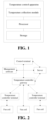
FIG. 1 is a schematic structural diagram of a temperature control apparatus of a central air conditioner according to an embodiment of the present invention; -
FIG. 2 is a schematic layout diagram of a temperature control system of a central air conditioner according to an embodiment of the present invention; -
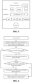
FIG. 3 is a schematic structural diagram of a temperature control apparatus of a central air conditioner according to an embodiment of the present invention; -
FIG. 4 is a schematic diagram of an APP main interface of a control terminal according to an embodiment of the present invention; -
FIG. 5 is a schematic diagram of an APP configuration interface of a control terminal according to an embodiment of the present invention; -
FIG. 6 is a flowchart of determining a network state by a control terminal according to an embodiment of the present invention; -
FIG. 7 is a schematic structural diagram of a temperature control system of a central air conditioner according to anembodiment 3 of the present invention; -
FIG. 8 is a flowchart of configuring a fan coil according to theembodiment 3 of the present invention; and -
FIG. 9 is a flowchart of a method for controlling a fan coil according to an embodiment of the present invention. - In order to solve the problems in the existing art, the present invention provides a temperature control apparatus of a central air conditioner, a method for controlling a fan coil and a medium, and the present invention will be further described below with reference to the drawings and embodiments. It is to be understood that the embodiments described herein are intended to explain and not to limit the present invention.
- As shown in
FIG. 1 , an embodiment of the present invention provides a temperature control apparatus of a central air conditioner, and the temperature control apparatus includes a temperature collection module, a storage and a processor. - The temperature collection module is configured to collect ambient temperature according to a set period.
- The storage is configured to store a fan coil control program, and the processor is configured to execute the fan coil control program to implement the following steps.
- If the temperature control apparatus is in a non-automatic working mode, a configuration instruction is received via a network, and a running state of the temperature control apparatus is configured according to the configuration instruction.
- If the temperature control apparatus is in an automatic working mode, a change trend of the ambient temperature is determined according to the collected ambient temperature; and the running state of the temperature control apparatus is configured according to the change trend of the ambient temperature.
- A corresponding control signal is sent to a fan coil connected with the temperature control apparatus according to the configured running state so as to enable the fan coil to start an action corresponding to the running state.
- The temperature collection module may be a temperature sensor, and the storage may be externally configured.
- The control terminal may employ any known terminal, such as a mobile phone and other mobile terminals. About the network, a wireless network may be adopted.
- The running state includes a cooling state, a heating state, and a ventilation state.
- The corresponding action of the running state may be opening or closing a solenoid valve of the fan coil, turning on or turning off a fan of the fan coil, or configuring a working speed of the fan.
- The configuration instruction may include a cooling command, a heating command, a ventilation command, and the like. In addition, the configuration instruction may further include: a switch-on instruction, a switch-off instruction, a timing instruction (including timing switch-on and timing switch-off), an entering-automatic-mode instruction, and an exiting- -automatic-mode instruction. After the temperature control apparatus receives the corresponding instruction, the working mode (also referred to as the running state) of the temperature control apparatus is configured.
- The temperature control apparatus may be a temperature controller terminal (also referred to as a temperature controller) or a temperature controller gateway.
- The non-automatic working mode indicates that for the temperature controller, the running state of the temperature controller needs to be configured by a user through the control terminal.
- The automatic working mode indicates that for the temperature controller, the running state of the temperature controller does not need to be configured by the user through the control terminal, and the temperature controller may configure the running state of the temperature controller itself according to the change trend of the ambient temperature.
- According to the embodiments of the present invention, the running state of the temperature control apparatus is configured through the control terminal, or the running state of the temperature control apparatus is automatically configured according to the change trend of the ambient temperature, so the problem that the existing temperature controller needs manual configuration is effectively solved and the control convenience of the existing temperature controller is improved.
- In other embodiments, the step of determining a change trend of the ambient temperature according to the collected ambient temperature includes the following steps.
- Collected ambient temperature is obtained at each period node.
- The change trend of the ambient temperature is determined according to the ambient temperature of the each period node.
- In other embodiments, the step of configuring the running state of the temperature control apparatus according to the change trend of the ambient temperature includes the following steps.
- If the change trend of the ambient temperature is a decreasing trend, the running state of the temperature control apparatus is configured to the cooling state, and a target cooling temperature is configured.
- If the change trend of the ambient temperature is an increasing trend, the running state of the temperature control apparatus is configured to the heating state, and a target heating temperature is configured.
- If the change trend of the ambient temperature is a flat trend, the running state of the temperature control apparatus is configured to the ventilation state.
- In other embodiments, the determining manner of the change trend of the ambient temperature includes the following manners.
- During a preset determining period, if the decreasing amplitude of the ambient temperature reaches a preset cooling threshold, the change trend of the ambient temperature is the decreasing trend.
- During the preset determining period, if the increasing amplitude of the ambient temperature reaches a preset heating threshold, the change trend of the ambient temperature is the increasing trend.
- During the preset determining period, if the change amplitude of the ambient temperature is within a preset ventilation threshold range, the change trend of the ambient temperature is the flat trend.
- One determining period may be comprised of two adjacent period nodes, or may be comprised of two or more adjacent period nodes.
- Certainly, in order to avoid interference from external factors, temperature collection uses a manner of sampling for multiple times to determine the running of the temperature controller. If the number of rises of the sampled temperature at the time of switch-on is greater than the number of drops of the sampled temperature, it is considered to be the hot wind, and the jitter data caused by external factors is discarded (a similar strategy is used for determining the cold wind).
- For example, in N determining periods, if the number of decreasing trends of the change trend of the ambient temperature is determined to be larger, the change trend of the ambient temperature is finally determined to be a decreasing trend; and if the number of increasing trends of the change trend of the ambient temperature is determined to be larger, the change trend of the ambient temperature is finally determined to be an increasing trend; where N is an odd number.
- In other embodiments, after the step of configuring the running state of the temperature control apparatus according to the change trend of the ambient temperature, the following steps are included.
- In the flat trend, the working speed of the fan of the fan coil is configured to be a low speed; where the working speed includes a low speed (i.e., a first preset rate), a medium speed (i.e., a second preset rate), and a high speed (i.e., a third preset rate).
- In the decreasing trend or the increasing trend, a working speed of a fan of the fan coil is configured according to a difference, where in the decreasing trend, the difference is a difference between currently acquired ambient temperature and the target cooling temperature, and in the increasing trend, the difference is a difference between the target heating temperature and the currently acquired ambient temperature. A temperature threshold T2 is less than a temperature threshold T1.
- In other embodiments, the step of configuring a working speed of a fan of the fan coil according to a difference includes the following steps.
- If the difference is greater than the preset temperature threshold T1 (i.e., a first temperature threshold), the working speed of the fan is configured to be the high speed.
- If the difference is less than the preset temperature threshold T2 (i.e., a second temperature threshold) and is not less than 0, the working speed of the fan is configured to be the low speed.
- If the difference is not less than the temperature threshold T2 and not greater than the temperature threshold T1, the working speed of the fan is configured to be the medium speed, where T2 is greater than 0.
- The method may further include: when the difference is equal to 0, a solenoid valve of the fan coil is configured to be in a closed state; when the difference is less than a preset temperature threshold T3 (i.e., a third temperature threshold), the fan is configured to be in a closed state, where the temperature threshold T3 is less than 0.
- After the step in which when the difference is less than the preset temperature threshold T3, the fan is configured to be in the closed state, the method further includes: in preset time, when the difference is greater than the preset temperature threshold T4 (i.e., a fourth temperature threshold), the solenoid valve and the fan are configured to be in a switch-on state, where the temperature threshold T4 is greater than 0.
- In other embodiments, the processor executes the temperature control computer program and further implements the following steps.
- Running data of the temperature control apparatus is determined, and the running data is sent to a preset server, so that the server generates an analysis chart.
- State data of the temperature control apparatus is sent to a control terminal that obtains control authority from the server.
- In other embodiments, the temperature control apparatus further includes a network connection module, which is configured to form a network with the control terminal and/or the server in a wireless or wired manner and interact with the intelligent terminal and/or the server about a control instruction and/or state data.
- In other embodiments, the step of receiving a configuration instruction via a network and configuring a running state of the temperature control apparatus according to the configuration instruction includes the following steps.
- The configuration instruction is received via a network, and a temperature control apparatus identifier is parsed from the configuration instruction, where the configuration instruction is any one of: a control instruction directly sent by the control terminal to the temperature control apparatus or the control instruction of the control terminal forwarded by the server to the temperature control apparatus.
- When the parsed temperature control apparatus identifier is consistent with its own temperature control apparatus identifier, the running state of the temperature control apparatus is configured according to the configuration instruction.
- In other embodiments, the temperature control apparatus identifier is a network address of the temperature control apparatus.
- Before the step of receiving the configuration instruction via a network and parsing a temperature control apparatus identifier from the configuration instruction, the method further includes the following steps.
- Heartbeat data is reported to the server, so that when the control instruction of the control terminal is received, the server forwards the received control instruction of the control terminal to a corresponding temperature control apparatus according to a preset mapping table of hardware addresses and network addresses, where the heartbeat data carries a hardware address of the temperature control apparatus.
- It is to be noted that the functional modules that are also involved in
FIG. 1 but are not described in the embodiment of the present invention are described in anembodiment 2. - As shown in
FIG. 2 , an embodiment of the present invention provides a temperature controller system of a central air conditioner, and the system includes any temperature control apparatus described in theembodiment 1, a control terminal, and a server. - The control terminal is configured to display and control the state of the temperature controller, for example, the control terminal is configured to obtain from the server a device list of temperature control apparatuses under control of the control terminal.
- The device list is displayed on a control interface.
- On the control interface, a temperature control apparatus selected by a user is received.
- A configuration instruction is sent to the selected temperature control apparatus.
- A control APP has been installed in the control terminal.
- The server is configured to manage authority of the temperature controller, display data statistics of the temperature control apparatus and forward a configuration instruction, and have communication data between the control APP and management software, where the management software is configured in the server.
- The temperature control apparatus is configured to control running of the fan coil and wirelessly communicate with the server module and the control terminal and automatically configure the mode, temperature, wind speed gear and switch of the temperature controller according to the ambient information.
- In other embodiments, the temperature control apparatus may be any one of a temperature controller terminal or a temperature controller gateway. With reference to
FIG. 3 , the temperature controller gateway is configured to control running of the fan coil and communicate with the server module and the temperature controller terminal module, and periodically report the heartbeat to the server module; the temperature controller gateway hardware mainly includes a network connection module, a processor, a real-time clock (RTC) clock, a temperature collection module (such as a temperature sensor), a light emitting diode (LED) indicator, a buzzer, a button, an external storage, a power supply module, and an liquid crystal display (LCD) touch screen. - The network connection module is connected to the Internet and is responsible for communicating with the server on the Internet. The network connection module includes at least one wireless network module, and the network connection module may further include a wireless network module or a wired network module, where the wireless network module is preferably a WiFi network processor.
- The network connection module is responsible for receiving the configuration instruction of the temperature controller forwarded by the network processor and forwarding the configuration instruction to the temperature controller gateway. The wired network module and the wireless network module transfer data to each other through the processor, and convert the data through a customized protocol. If the wireless network module has the function of connecting to the Internet, the network processor for connecting to the Internet may be removed from the gateway device hardware. The wireless network module may be configured with a power amplifier configured to amplify the wireless signal of the wireless network module, so that the wireless signal is transmitted farther; certainly, the power amplifier may also be configured in the wired network module.
- A processor is configured to control the signal lines of the fan coil and to connect the various hardware modules.
- The RTC clock module is configured to perform timing and obtain server time in real time for time check.
- The temperature collection module is configured to collect ambient temperature.
- The LED indicator is configured to indicate the running state of the temperature controller and the network state.
- The buzzer is configured for device identification during networking.
- The external storage is configured to store the fan coil control program, the running version files of each chip and some key data of the temperature controller during running.
- The button is mainly configured to have functions of configuring a state of the temperature controller, resetting the device, and restoring the factory configurations.
- The power supply module is configured to power the device.
- The LCD touch screen is an optional module, and is configured to display the state of the temperature controller and configure the temperature controller. If the user requires the usage habits of the conventional temperature controller panel to be compatible, the LCD touch screen is configured; if the user is more accustomed to using the control terminal for remote operation, the LCD touch screen is not configured.
- The temperature controller gateway itself is also a temperature controller. Compared with the temperature controller terminal, one more network processor exists, and the performance configurations of the wireless network module and the performance configurations of other hardware are stronger than those of the terminal device. According to the needs of the user, the gateway may be independent, and the function of the temperature controller is not integrated. Each temperature controller system requires at least one gateway device or multiple gateway devices may be deployed.
- As shown in
FIG. 3 , the hardware of the temperature controller terminal device mainly includes a wireless network module, a processor, an RTC clock, a temperature collection module, an LED indicator, a buzzer, an external storage, a button, a power supply module, an LCD touch screen, and may also include a timing switch module, a lock and unlock module, a statistics module, and a reporting module. If the wireless network module has a Mesh (wireless grid network) network function, the wireless network module is configured to communicate with the wireless network module of the gateway device or the wireless network module of the next hop. Other components have the same function as a gateway component. Each temperature controller system has zero, one or multiple terminal devices. The temperature controller is installed in the range of about 1 meter from the fan coil outlet to save wiring. - 1. The temperature controller terminal may be configured with a software module. The software module is mainly responsible for intelligent automatic running of the temperature controller, control over the fan coil, reporting of the daily running state statistics of the temperature controller, timing of the temperature controller, processing of the timer configured by the user and other functions. The temperature controller terminal automatically records the running time of each gear and mode every day, and reports the statistical data (i.e., running data) to the server after 0 a.m. the next day.
- The timing switch function is configured by the user in the APP of the control terminal (such as a mobile phone). The software module of the temperature controller terminal stores the configurations, and after the time point configured by the user is reached, the switch-on and switch-off configurations are automatically performed on the temperature controller. An example of the main interface and an example of the configuration interface of the APP are shown in
FIG. 4 andFIG. 5 respectively. - The wireless network module is mainly responsible for wireless communication and data forwarding. The wireless network module includes network processor software and a network processor, and is mainly responsible for performing protocol conversion between the wireless network module and the network processor, reporting the heartbeat to the server, collecting the online state of each temperature controller terminal and ambient temperature, and other functions.
- For automatically running of the temperature controller terminal, the following technical solution is used: after the temperature controller terminal is energized, the temperature collection module starts to periodically collect the ambient temperature data. The temperature controller terminal automatically configures the running state, temperature, and gear of the temperature controller by determining the change of the ambient temperature.
- In order to avoid interference from external factors, temperature collection uses a manner of sampling for multiple times to determine the running of the temperature controller terminal. If the number of rises of the sampled temperature at the time of switch-on is greater than the number of drops of the sampled temperature, it is considered to be the hot wind, and the jitter data caused by external factors is discarded (a similar strategy is used for determining the cold wind). When the fan coil emits the cold wind, the temperature controller terminal is automatically configured to be a default cooling temperature. If the ambient temperature is lower than the default cooling temperature, the solenoid valve is closed and fan of the fan coil is turned off. If the ambient temperature is higher than the default cooling temperature, the gear of the fan is configured according to the magnitude of difference between the ambient temperature and the configured temperature. When the hot wind is emitted, the temperature of the temperature controller is automatically configured to be a default heating temperature. If the ambient temperature is higher than the default heating temperature, the solenoid valve is closed and the fan of the fan coil is turned off. If the ambient temperature is lower than the default heating temperature, the gear of the fan is configured according to the magnitude of difference between the ambient temperature and the configured temperature.
- The default cooling temperature of the system is 26°C, and the default heating temperature of the system is 20°C, and these values are also the government's recommended value for temperature configuration in the office area. The default configuration temperature may effectively reduce energy consumption of the central air conditioner, and in special cases, the user may configure other temperature values. After the user configures other temperature, the temperature for closing the solenoid valve of the fan coil and turning off the fan is automatically adjusted accordingly.
- If the user configures the mode and the wind speed of the temperature controller terminal after turning on the temperature controller terminal, the temperature controller terminal runs according to the configurations of the user, and the automatic mode does not take effect. The automatic mode takes effect again after the user selects the automatic mode.
- In other embodiments, the software module of the temperature controller terminal includes the following program modules.
- An anti-shake module is configured to screen the effective change information of the collected temperature.
- A first determining module is configured to determine the change trend, e.g., higher or unchanged, of the ambient temperature after the temperature controller is turned on.
- A temperature mode automatic configuration module is configured to configure the running mode to heating when the first determining module indicates an increasing trend and configure the default heating temperature; configure the running mode to be cooling when the first determining module indicates a decreasing trend and configure the default cooling temperature (i.e., the target temperature); and configure the running mode to be ventilation when the first determining module indicates that the temperature is unchanged.
- A second determining module is configured to determine the difference between the ambient temperature and the default temperature under the decreasing trend; and determine the difference between the default temperature and the ambient temperature under the increasing trend.
- A fan gear automatic configuration module is configured to configure the fan gear to be a low speed when the first determining result indicates that the temperature is unchanged.
- The fan gear automatic configuration module is further configured to configure the working speed of the fan to be the third preset rate if the difference is greater than the preset temperature threshold T1.If the difference is less than the preset temperature threshold T2 and not less than 0, the working speed of the fan is configured to be the first preset rate.
- If the difference is not less than the temperature threshold T2 and not greater than the temperature threshold T1, the working speed of the fan is configured to be the second preset rate; where the first preset rate is lower than the second preset rate, and the second preset rate is lower than the third preset rate; and the temperature threshold T2 is less than the temperature threshold T1.
- A switch-on and switch-off automatic configuration module is configured to configure the solenoid valve of the fan coil to be in a closed state when the difference is equal to 0. When the difference is less than a preset temperature threshold T3, the fan is configured to be in a turn-off state; where the temperature threshold T3 is less than 0.
- For example, when the temperature mode automatic configuration module configures the mode to be cooling and the temperature difference determined by the second determining module is 0, the solenoid valve of the fan coil is configured to be closed, when the temperature difference of the second determining module is lower than the configuration temperature T3, the fan of the fan coil is configured to be turned off, and after a period of turn-off, when the temperature difference determined by the second determining module is higher than the configuration temperature T4, the fan is automatically turned on and the solenoid valve automatically opens; when the temperature mode automatic configuration module configures the mode to be heating and the temperature difference of the second determining module is 0, the solenoid valve of the fan coil is configured to be closed, when the temperature difference of the second determining module is lower than the configuration temperature T3, the fan of the fan coil is configured to be turned off, and after a period of turn-off, when the temperature difference of the second determining module is higher than the configuration temperature T4, the fan is automatically turned on and the solenoid valve automatically opens.
- The processor is configured to control the temperature controller and connect the hardware components of the temperature controller; and is configured to respond to the configuration instructions of various temperature, modes, gears and switches of the control terminal APP and control the running of the fan coil.
- The timing switch module is configured to automatically switch on or switch off after the timing switch-on/-off time configured by the user is up.
- The lock and unlock module is configured to, after the administrator locks the temperature controller, not allow other users to perform remote configuration on the temperature controller, and also not allow configuration of buttons on the LCD panel.
- The statistics module is configured to automatically count the daily running time of the temperature controller in various modes and gears, and obtain the running data of the temperature controller.
- The reporting module is configured to report the running data of the temperature controller terminal to the server.
- 2. The server is mainly responsible for communication with the temperature controller terminal device, the temperature controller gateway device and the control terminal; the server is also responsible for the user's login authority management, user authorization management and user operation log statistics. The server is generally deployed on a cloud server or deployed on a server built by itself.
- The server includes a statistical data storage module, an operation log storage module, an authority management module, a statistical data charting module and an operation log query module.
- The statistical data storage module is configured to store statistical data of the temperature control apparatus in a database.
- The operation log storage module is configured to store the user's remote operation record in an operation log.
- The authority management module is configured to send information of the authorized devices to the control terminal when the control terminal requests a device list.
- The statistical data charting module is configured to plot data in the database into a chart on the management software.
- The operation log query module is configured for an administrator to query the above operation log.3. The control terminal displays the state of the temperature control apparatus, controls the temperature control apparatus, responds to various operations of the user, configures the installation address and name of the temperature control apparatus, and configures the timing switch time of the temperature control apparatus through the APP. When the network processor of the temperature controller gateway device is a WiFi network processor, the control terminal is also responsible for configuring the connection between the WiFi module of the gateway and the wireless router. The control terminal may also intelligently select whether to communicate with the gateway in the local area network directly or through the server according to the network condition. The APP mainly includes the Android platform and the IOS platform, and the platform may also be extended to other smartphone platforms.
- In other embodiments, the control terminal may include a temperature controller monitoring module, a timer configuration module, an authorization module, a configuration module, a batch configuration module and an automatic determining internal or external network module.
- The temperature controller monitoring module is configured to view and configure the state of the temperature control apparatus for the user.
- The timer configuration module is configured to configure timing switch-on/-off for the temperature control apparatus by the user.
- The authorization module is configured for an administrator to give other users the authorization of certain specified temperature control apparatuses.
- The configuration module is configured for the administrator to configure the address and name of a newly installed temperature control apparatus.
- The batch configuration module is configured for the administrator to configure multiple temperature control apparatuses at one time.
- The automatic determining internal or external network module has following functions. When the temperature control apparatus and the control terminal are in the same local area network, the control of the temperature control apparatus automatically takes the local area network control, and transfer through the server is not needed; when the temperature control apparatus and the control terminal are not in the same local area network, transfer through the server is needed; and the internal network or the external network is automatically determined by the APP and does not need to be configured by the user. The mobile phone as the control terminal is taken as an example, and the process is shown in
FIG. 6 . - In
step 1, an app is started. - In
step 2, it is initially configured that the control command of the temperature controller is forwarded by a server, and a network of the mobile phone is detected. - In
step 3, whether the mobile phone is connected to WiFi is determined. If the mobile phone is connected to WiFi,step 4 is executed, and if the mobile phone is not connected to WiFi,step 7 is executed. - In
step 4, gateway messages are searched for by broadcasting in a local area network. - In
step 5, whether a gateway device gives a response in the local area network is determined. If a gateway device gives a response,step 6 is executed, if no gateway device gives a response,step 7 is executed. - In
step 6, communication flags of all devices under the gateway are configured to be in an internal network mode. - In
step 7, control commands of the mobile phone are forwarded by the server. - 4. The system may also include a management software module which includes a web server and a client module. The management software module is configured to manage deletion, modification, authorization and the like of the temperature controller, make switch-on time statistics of the temperature controller and perform charting, make operation log statistics of the temperature controller, and the like. The management software module mainly communicates with the server. The management software module may also use management software having C/S architecture.
- The system in the embodiment of the present invention has the following technical effects.
- 1. According to the embodiments of the present invention, a method for controlling a fan coil by using a smart phone is introduced, which is convenient for remote management by a user, and can be used by any smart phone by installing an APP.
- 2. According to the embodiments of the present invention, a big data analysis is made based on the temperature data collected by the temperature control apparatus, and a set of automatic operation system of the temperature control apparatus is designed. In most cases, the user only needs to configure the switch of the temperature control apparatus, and does not need to configure the mode, the wind speed, the temperature and other information of the temperature control apparatus. After the user configures the timing switch time of the temperature control apparatus, the user may no longer control the running of the temperature control apparatus, and the temperature control apparatus runs intelligently and automatically.
- 3. Due to remote management, the temperature control apparatus may be installed near (about 1 meter) the outlet of the fan coil, so the wiring is reduced and the networking cost of the user is saved.
- 4. The temperature control apparatus automatically counts and reports the total switch-on and the running time of each gear and mode each day to the server. After the server stores the data, the data is provided to the control terminal and the management software, and statistical charts of daily, weekly, and monthly running conditions of the temperature control apparatus are drawn on the control terminal and the management software. It is convenient for users to analyze the running state and energy consumption state of the temperature controller.
- 5. The functions of timing switch of the temperature apparatus, batch management of the temperature control apparatus and locking of the temperature control apparatus are provided for the administrator users. The management is more convenient and the energy saving effect is more significant.
- 6. The administrator user can operate on the control terminal or the management software to give authorization to other users. After the other users are authorized, the other users can use the control terminal to control the authorized temperature control apparatus and view the running state of the temperature control apparatus.
- 7. If the control terminal and the gateway of the temperature control apparatus are in the same WiFi, the control terminal can control the temperature control apparatus directly through a local area network without connecting to the Internet to save the user traffic and ensure the real-time performance of controlling the temperature control apparatus. Even if the connection of the WiFi router and the Internet is disconnected, monitoring of the temperature control apparatus by the user is not affected. If the control terminal and the gateway are not in the same WiFi, the control terminal needs to be connected to the Internet, the LAN control or the Internet control is automatically determined by the control terminal, and no user intervention is required.
- 8. The power amplifier module is added to the hardware of the temperature control apparatus to make the wireless data transmission distance between the temperature controllers longer.
- As shown in
FIG. 7 , according to the embodiment, the operation of a single temperature control apparatus is achieved on a mobile phone. The network processor in the gateway hardware of the temperature controller utilizes the WiFi module of the ESP8266 chip, and the wireless network module utilizes the CC2538 module as the ZigBee coordinator. The wireless network module in the hardware of the temperature controller terminal utilizes the CC2530 module as the Zigbee router. The processor utilizes Xintang 0516 single chip microcomputer. As shown inFIG. 8 , the operation flow includes the following steps. - In
step 1, an app is started. - In
step 2, an APP user logs in; the APP user may login to the APP with the mobile phone number of the APP user itself, and obtain an short-message verification code as a login password. The server verifies whether the verification code is correct, and after the verification is passed, the user logs in successfully. - In
step 3, server configuration is requested. - In
step 4, the server determines whether the control authority of the temperature controller exists. After the user logs in successfully, the server finds out in the server which temperature controller devices the user has control authority according to the user's mobile phone number, and returns the list of authorized devices to the APP. The APP displays the list of devices on the APP interface. If the user does not have an authorized device, step 14 is executed. - In
step 5, the APP obtains the device list and queries the online state of the device, as shown inFIG. 4 . - In
step 6, whether the device is online is determined. If the device is online, the user may enter the APP configuration interface and add a new device in the configuration interface. If a new temperature controller device currently exists, after the button of add new device is clicked, the new temperature controller will be displayed in the interface to be configured. After the button of enter is clicked, the new temperature controller may be named and configured, and after configuration is completed,step 7 is executed. If the device is not online,step 13 is executed. - In
step 7, the real-time state of the device is queried. The state of the temperature controller mainly includes the state of a fan speed (high speed, medium speed, and low speed), current ambient temperature, configuration temperature of the temperature control apparatus, the mode state (automatic, cooling, heating, ventilation) of the temperature control apparatus, the switch state and the lock state. - In
step 8, whether the device is locked is determined. If the device is locked,step 12 is executed; if the device is not locked,step 9 is executed. - In
step 9, whether the device needs to be controlled is determined. If the device needs to be controlled,step 11 is executed; if the device does not need to be controlled,step 10 is executed. - In
step 10, each control button as shown inFIG. 5 is clicked. - In other embodiments, the control of the temperature controller mainly includes fan speed configuration (high speed, medium speed, and low speed), temperature setting, mode configuration (automatic, cooling, heating, ventilation) of the temperature controller, switch configuration, timing switch configuration, and lock device configuration.
- In the APP, the IEEE address of the device to be controlled is filled in the communication interface. After receiving the control command, the Zigbee coordinator module of the gateway device determines whether the IEEE address is its own address. If the IEEE address is its own address, the Zigbee coordinator module of the gateway device directly sends a command to the MCU to control the fan coil of the air conditioner. If the IEEE address is not its own address, the Zigbee coordinator of the gateway device originally encapsulates the control command of the APP, queries the routing table, and sends the control command to the next-hop zigbee router.
- The Zigbee router determines whether the destination IEEE address of the received control command is its own IEEE address. If the destination IEEE address of the received control command is its own IEEE address, the Zigbee router sends a command to the microcontroller unit (MCU) to control the fan coil of the air conditioner. If the destination IEEE address of the received control command is not its own IEEE address, the Zigbee router continues to send the control command to a next hop until the control command is sent to the corresponding Zigbee router.
- When the mobile phone sends the control command (i.e., the configuration instruction) to the temperature controller, the mobile phone checks the network connection manner of the control APP.
- If the mobile phone connection is in the mobile network manner, the control command is forwarded through the server. If the mobile phone connection is in the WiFi manner, the control APP scans the gateway devices in the local area network. If a gateway device gives a response in the local area network, the gateway is marked as an internet device, the communication between the control APP and the gateway device adopts the manner of direct communication in the local area network, and transfer through the server is not needed. The gateway device that does not give a response is marked as the external network device, and communicates with the device via transfer through the server.
- In
step 11, exiting is executed. - In
step 12, if the temperature control apparatus is in a locked state, no other operation can be executed on the temperature control apparatus, and the administrator is contacted to release the locked state of the temperature control apparatus or exiting is executed. - In
step 13, a not online state is displayed. - In step 14, the device is configured or the administrator is contacted for authorization. For example, if a new temperature controller device does not exist currently, the administrator is contacted to authorize the temperature controller usage authority for a user. The administrator authorizes the user through a control APP software or a web software.
- According to the embodiment, the control of multiple temperature controller devices (which may be all devices) on the smart phone at the same time is implemented. The embodiment is mainly used for the administrator to batch control the temperature controllers. The following steps are included.
- In step A, an APP user logs in.
- The APP user logs in to the APP with its own mobile phone number, and obtain a short-message verification code as a login password. The server verifies whether the verification code is correct, and after the verification is passed, the user logs in successfully.
- In step B, the APP obtains a list of devices.
- After the user logs in successfully, the APP finds out in the server which temperature controller devices the user has control authority according to the user's mobile phone number, the list of authorized devices is returned to the APP, and the APP displays the list of devices on the app interface.
- In step C, the user enters a batch configuration interface of the control APP.
- In step D, a batch control of the temperature controllers is executed.
- The batch control of the temperature controllers mainly includes fan speed configuration (high speed, medium speed, and low speed), temperature setting, mode configuration (automatic, cooling, heating, ventilation) of the temperature controller, switch configuration, timing switch configuration, and lock device configuration.
- After the user enters the batch configuration interface, the user selects multiple devices that need to be configured in batch. After the batch configuration button is clicked, the APP sends control commands one by one to the devices according to the solution in the
embodiment 3. - According to the embodiment, automatic running of the temperature controller device is implemented. The following steps are included.
- In step A, the device is energized.
- The power supply of the device is normal, and the hardware, software, and temperature sensors run normally.
- In step B, the device collects the ambient temperature.
- The temperature sensor of the device collects the ambient temperature every 5 seconds and records the collected temperature.
- In step C, the device is turned on.
- The user remotely operates the device with the mobile phone to be turned on and configures the device to be in an automatic mode (or the user remotely operates the device with the mobile phone to be turned on and the device enters the automatic mode by default if no operation is performed within a predetermined time) or the device is turned on automatically by the timer of the device.
- In step D, the device determines the change trend of the ambient temperature.
- If the ambient temperature is slowly decreasing, it is considered that the fan coil outlet gives out cold air, and the process proceeds to step E. If the ambient temperature is slowly increasing, it is considered that the fan coil outlet gives out hot air, and the process proceeds to step F. If the ambient temperature is unchanged, it is considered that the fan coil outlet gives out natural air, and the central air conditioner has no cooling or heating. The fan gear of the temperature controller is configured to low.
- In step E, the target temperature is automatically configured to 26 °C, and the mode is configured to a cooling state.
- For example, in an increasing trend, if the ambient temperature is greater than 30 °C, the fan gear of the air conditioner is configured to a high-gear; if the ambient temperature is greater than 27 °C and less than 30 °C, the fan gear of the air conditioner is configured to a mid-gear; if the ambient temperature is greater than 26 °C and less than 27 °C, the fan gear of the air conditioner is configured to a low-gear; if the ambient temperature is less than 26 °C, the solenoid valve is closed; if the temperature continues to decrease after the solenoid valve is closed, the fan is turned off. After switch-off for some time, if the ambient temperature is greater than 26.5 °C, the solenoid valve is opened and the fan is turned on again.
- In step F, the target temperature is automatically configured to 20 °C, and the mode is configured to a heating state.
- If the ambient temperature is less than 16° C, the fan gear of the air conditioner is configured to a high-gear; if the ambient temperature is greater than 16 °C and less than 19 °C, the fan gear of the air conditioner is configured to a mid-gear; if the ambient temperature is greater than 19°C and less than 20°C, the fan gear of the air conditioner is configured to a low-gear; if the ambient temperature is greater than 20 °C, the solenoid valve is closed; if the temperature continues to increase after the solenoid valve is closed, the fan is turned off. After switch-off for some time, if the ambient temperature is less than 19.5 °C, the solenoid valve is opened and the fan is turned on again.
- According to the embodiment, the control of a single temperature control apparatus on a smart phone is implemented. The wireless communication technology of the temperature control apparatus adopts narrow band-internet of things (NB-IoT), the subscriber identity module (SIM) card with the NB-IoT chip is installed on the temperature control apparatus, and the temperature control apparatus periodically reports a heartbeat to the server, where the heartbeat includes a hardware address of the SIM card. The following steps are included.
- In step A, an APP user logs in.
- The APP user logs in to an APP with its own mobile phone number, and obtains a short-message verification code as a login password. The server verifies whether the verification code is correct, and after the verification is passed, the user logs in successfully.
- In step B, the APP obtains a list of devices.
- After the user logs in successfully, the APP finds out in the server which temperature control apparatuses the user has control authority according to the user's mobile phone number, the list of authorized devices is returned to the app, and the APP displays the list of devices on the app interface.
- In step C, the state of the temperature control apparatus is queried.
- The state of the temperature control apparatus mainly includes the state of the fan speed (high speed, medium speed, and low speed), current ambient temperature, configuration temperature of the temperature control apparatus, the mode state (automatic, cooling, heating, ventilation) of the temperature control apparatus , the switch state and the lock state.
- In step D, a control of the temperature control apparatus is executed.
- The control of the temperature control apparatus mainly includes fan speed configuration (high speed, medium speed, and low speed), temperature setting, mode configuration (automatic, cooling, heating, ventilation) of the temperature control apparatus, switch configuration, timing switch configuration and lock device configuration.
- In the APP, the NB-IoT hardware address of the controlled temperature control apparatus is filled in the communication interface and a control command is sent to the server. The server forwards the control command to the corresponding temperature control apparatus by checking the mapping table of the hardware address and the network address.
- According to the embodiment, the control of a single temperature control apparatus on a smart phone is implemented. The wireless communication technology of the temperature controller adopts LoRa, a LoRa network processor is installed on the temperature controller, and the LoRa network processor periodically reports a heartbeat to the server, where the heartbeat includes a hardware address of the LoRa. The data processing method includes the following steps, and the hardware address belongs to one of the temperature control apparatus identifiers.
- In step A, an APP user logs in.
- The APP user logs in to an APP with its own mobile phone number, and obtains a short-message verification code as a login password. The server verifies whether the verification code is correct, and after the verification is passed, the user logs in successfully.
- In step B, the APP obtains a list of devices.
- After the user logs in successfully, the APP finds out in the server which temperature control apparatuses the user has control authority according to the user's mobile phone number, the list of authorized apparatuses is returned to the APP, and the APP displays the list of devices on the app interface.
- In step C, the state of the temperature control apparatus is queried.
- The state of the temperature control apparatus mainly includes the state of the fan speed (high speed, medium speed, and low speed), current ambient temperature, configuration temperature of the temperature controller, the mode state (automatic, cooling, heating, ventilation) of the temperature controller, the switch state, and the lock state.
- In step D, a control of the temperature control apparatus is executed.
- The control of the temperature control apparatus mainly includes fan speed configuration (high speed, medium speed, and low speed), temperature setting, mode configuration (automatic, cooling, heating, ventilation) of the temperature controller, switch configuration, timing switch configuration and lock device configuration.
- In the APP, the LoRa hardware address of the device to be controlled is filled in the communication interface, and a control command is sent to the server. The server forwards the control command to the corresponding temperature controller by checking the mapping table of the hardware address and the network address.
- As shown in
FIG. 9 , a method for controlling a fan coil is provided in an embodiment of the present invention and applied to a temperature control apparatus of an air conditioner, and the method includes the following steps. - In step S101, a running state is configured through a control terminal or is in an automatic mode.
- The step includes: if the temperature control apparatus is in a non-automatic working mode, a configuration instruction is received via a network, and the running state of the temperature control apparatus is configured according to the configuration instruction.
- If the temperature control apparatus is in an automatic working mode, ambient temperature is collected according to a set period; a change trend of the ambient temperature is determined according to the collected ambient temperature; and the running state of the temperature control apparatus is configured according to the change trend of the ambient temperature.
- In
step S 102, a corresponding control signal is sent to a fan coil connected with the temperature control apparatus according to the configured running state so as to enable the fan coil to start an action corresponding to the running state. - According to the embodiment of the present invention, the running state of the temperature control apparatus is configured through the control terminal, or the running state of the temperature control apparatus is automatically configured according to the change trend of the ambient temperature, so the problem that the existing temperature controller needs manual configuration is effectively solved and the control convenience of the existing temperature controller is improved.
- In other embodiments, the step of determining a change trend of the ambient temperature according to the collected ambient temperature includes the following steps.
- Collected ambient temperature is obtained at each period node.
- The change trend of the ambient temperature is determined according to the ambient temperature of the each period node.
- In other embodiments, the running state includes a cooling state, a heating state, and a ventilation state.
- The step of configuring the running state of the temperature control apparatus according to the change trend of the ambient temperature includes the following steps.
- If the change trend of the ambient temperature is a decreasing trend, the running state of the temperature control apparatus is configured to the cooling state, and a target cooling temperature is configured.
- If the change trend of the ambient temperature is an increasing trend, the running state of the temperature control apparatus is configured to the heating state, and a target heating temperature is configured.
- If the change trend of the ambient temperature is a flat trend, the running state of the temperature control apparatus is configured to the ventilation state.
- In other embodiments, the determining manner of the change trend of the ambient temperature includes the following manners.
- During the preset number of periods, if decreasing amplitude of the ambient temperature reaches a preset cooling threshold, the change trend of the ambient temperature is the decreasing trend.
- During the preset number of periods, if the increasing amplitude of the ambient temperature reaches a preset heating threshold, the change trend of the ambient temperature is the increasing trend.
- During the preset number of periods, if the change amplitude of the ambient temperature is within a preset ventilation threshold range, the change trend of the ambient temperature is the flat trend.
- In other embodiments, after the step of configuring the running state of the temperature control apparatus according to the change trend of the ambient temperature, the following steps are included.
- In the flat trend, the working speed of the fan of the fan coil is configured to a low speed; where the working speed includes a low speed, a medium speed, and a high speed.
- A working speed of a fan of the fan coil is configured according to a difference in the decreasing trend or the increasing trend, where in the decreasing trend, the difference is a difference between currently acquired ambient temperature and the target cooling temperature, and in the increasing trend, the difference is a difference between the target heating temperature and the currently acquired ambient temperature.
- The step of configuring a working speed of a fan of the fan coil according to a difference includes the following steps.
- If the difference is greater than a preset temperature threshold T1, the working speed of the fan is configured to the high speed.
- If the difference is less than the preset temperature threshold T2 and not less than 0, the working speed of the fan is configured to the low speed.
- If the difference is not less than the temperature threshold T2 and not greater than the temperature threshold T1, the working speed of the fan is configured to the medium speed.
- Certainly, the step of configuring a working speed of a fan of the fan coil according to a difference further includes the following steps.
- When the difference is equal to 0, a solenoid valve of the fan coil is configured to be in a closed state.
- When the difference is less than a preset temperature threshold T3, the fan is configured to be in a closed state; where the temperature threshold T3 is less than 0.
- After the step in which when the difference is less than the preset temperature threshold T3, the fan is configured to be in the closed state, the following steps are included.
- Within preset time, when the difference is greater than a preset temperature threshold T4, the solenoid valve and the fun are configured to be in a switch-on state, where the temperature threshold T4 is greater than 0.
- In other embodiments, the method further includes the following steps.
- Running data of the temperature control apparatus is determined, and the running data is sent to a preset server, so that the server generates an analysis chart.
- State data of the temperature control apparatus is sent to a control terminal that obtains control authority from the server.
- In other embodiments, the step of receiving a configuration instruction via a network and configuring a running state of the temperature control apparatus according to the configuration instruction includes the following steps.
- The configuration instruction is received via the network, and a temperature control apparatus identifier is parsed from the configuration instruction, where the configuration instruction is any one of: a control instruction directly sent by the control terminal to the temperature control apparatus or the control instruction of the control terminal forwarded by the server to the temperature control apparatus.
- When the parsed temperature control apparatus identifier is consistent with its own temperature control apparatus identifier, the running state of the temperature control apparatus is configured according to the configuration instruction.
- In other embodiments, the temperature control apparatus identifier is a network address of the temperature control apparatus.
- Before the step of receiving the configuration instruction via a network and parsing a temperature control apparatus identifier from the configuration instruction, the method further includes the following steps.
- Heartbeat data is reported to the server, so that when the control instruction of the control terminal is received, the server forwards the received control instruction of the control terminal to a corresponding temperature control apparatus according to a preset mapping table of hardware addresses and network addresses, where the heartbeat data carries a hardware address of the temperature control apparatus.
- According to an embodiment of the present invention, a computer-readable storage medium is provided and stores a fan coil control program which, when executed by at least one processor, implements the steps of any method in the
embodiment 8. - According to the embodiment of the present invention, for the implementation by the storage medium, reference may be made to the above method embodiments, and no further description is provided herein.
- The computer readable storage medium in embodiments of the present invention may be a random access memory (RAM) memory, a flash memory, a read-only memory (ROM), an Erasable Programmable Read-Only Memory (EPROM) memory, an Electrically Erasable Programmable Read-only Memory (EEPROM) memory, a register, a hard disk, a removable hard drive, a compact disc read-only memory (CD-ROM), or any other form of storage medium known in the art. A storage medium may be coupled to the processor, so that the processor can read information from the storage medium and write information to the storage medium, or the storage medium may be a component of the processor. The processor and the storage medium may be located in an application specific integrated circuit.
- It should be understood that "one embodiment" or "an embodiment" mentioned throughout the description refers to that a particular feature, structure or characteristic related to the embodiments is included in at least one embodiment of the present invention. Therefore, the phrase "in one embodiment" or "in an embodiment" in various places throughout the description does not necessarily refer to the same embodiment. In addition, these particular features, structures or characteristics may be combined in one or more embodiments in any suitable manner. It should be understood that in various embodiments of the present invention, the serial numbers of the above processes do not mean the execution order and the execution order of the above processes should be determined according to their functions and internal logics, which should not limit the implementation processes of the present invention in any improper way. The above serial numbers of the embodiments of the present invention are merely for ease of description and do not indicate superiority and inferiority of the embodiments.
- It is to be noted that as used herein, the term "comprising", "including" or any other variant thereof is intended to encompass a non-exclusive inclusion so that a process, method, article or apparatus that includes a series of elements not only includes those elements but also includes other elements that are not expressly listed or are inherent to such a process, method, article or apparatus. In the absence of more restrictions, the elements defined by the statement "including a ..." do not exclude the presence of additional identical elements in the process, method, article or apparatus that includes the elements.
- It should be understood that the devices and the methods disclosed in the embodiments of the present application may be implemented in other ways. The device embodiments described above are merely illustrative. For example, the unit division is merely a logical function division, and, in practice, the unit division may be implemented in other ways. For example, multiple units or components may be combined or may be integrated into another system, or some features may be omitted or not executed. In addition, coupling, direct coupling or communication connections between the presented or discussed components may be indirect coupling or communication connections, via interfaces, between devices or units, and may be electrical, mechanical or in other forms.
- The above are merely embodiments of the present invention and are not intended to limit the present invention. It is easy for those skilled in the art to conceive modifications or substitutions within the technical scope of the present invention as long as these modifications or substitutions are within the scope of the protection of the present invention. Therefore, the protection scope of the present invention is solely defined by the appended claims.
- The running state of the temperature control apparatus is configured through the control terminal, or the running state of the temperature control apparatus is automatically configured, so the problems that the existing temperature controller needs to be manually configured and that the configuration process is troublesome are effectively solved.
Claims (13)
- A method for controlling a fan coil, applied to a temperature control apparatus of a central air conditioner, wherein the temperature control apparatus is configured to be in a non-automatic working mode or in an automatic working mode, and characterized by comprising:in a case where the temperature control apparatus is in a non-automatic working mode, receiving (S101) a configuration instruction, and configuring a running state of the temperature control apparatus according to the configuration instruction;in a case where the temperature control apparatus is in an automatic working mode, collecting ambient temperature according to a set period; determining a change trend of the ambient temperature according to the collected ambient temperature; and configuring (S101) the running state of the temperature control apparatus according to the change trend of the ambient temperature; andsending (S102) a control signal corresponding to the configured running state to the fan coil connected with the temperature control apparatus according to the configured running state so as to enable the fan coil to start an action corresponding to the running state;wherein the running state comprises a cooling state, a heating state, and a ventilation state;wherein the configuring (S101) the running state of the temperature control apparatus according to the change trend of the ambient temperature comprises:in response to determining that the change trend of the ambient temperature is a decreasing trend, configuring the running state of the temperature control apparatus to the cooling state, and configuring a target cooling temperature;in response to determining that the change trend of the ambient temperature is an increasing trend, configuring the running state of the temperature control apparatus to the heating state, and configuring a target heating temperature; andin response to determining that the change trend of the ambient temperature is a flat trend, configuring the running state of the temperature control apparatus to the ventilation state.
- The method of claim 1, wherein the determining a change trend of the ambient temperature according to the collected ambient temperature comprises:acquiring collected ambient temperature at each of a plurality period nodes; anddetermining the change trend of the ambient temperature according to the ambient temperature at the period nodes.
- The method of claim 1, wherein the change trend of the ambient temperature is determined in one of following manners:during a preset determining period, in response to determining that decreasing amplitude of the ambient temperature reaches a preset cooling threshold, the change trend of the ambient temperature is the decreasing trend;during the preset determining period, in response to determining that increasing amplitude of the ambient temperature reaches a preset heating threshold, the change trend of the ambient temperature is the increasing trend; andduring the preset determining period, in response to determining that change amplitude of the ambient temperature is within a preset ventilation threshold range, the change trend of the ambient temperature is the flat trend.
- The method of claim 1, wherein after the configuring the running state of the temperature control apparatus according to the change trend of the ambient temperature, the method further comprises:
configuring a working speed of a fan of the fan coil according to a difference in the decreasing trend or the increasing trend, wherein in the decreasing trend, the difference is a difference between currently acquired ambient temperature and the target cooling temperature, and in the increasing trend, the difference is a difference between the target heating temperature and the currently acquired ambient temperature. - The method of claim 4, wherein the configuring a working speed of a fan of the fan coil according to a difference comprises:in response to determining that the difference is greater than a preset first temperature threshold, configuring the working speed of the fan to a third preset rate;in response to determining that the difference is less than a preset second temperature threshold and not less than 0, configuring the working speed of the fan to a first preset rate; andin response to determining that the difference is not less than the second temperature threshold and not greater than the first temperature threshold, configuring the working speed of the fan to a second preset rate; wherein the first preset rate is lower than the second preset rate, and the second preset rate is lower than the third preset rate; and the second temperature threshold is less than the first temperature threshold.
- The method of claim 5, wherein the configuring a working speed of a fan of the fan coil according to a difference further comprises:in response to determining that the difference is equal to 0, configuring a solenoid valve of the fan coil to be in a closed state; andin response to determining that the difference is less than a preset third temperature threshold, configuring the fan to be in a closed state; wherein the third temperature threshold is less than 0.
- The method of claim 6, wherein after the in response to determining that the difference is less than a preset third temperature threshold, configuring the fan to be in a closed state, the method further comprises:
in response to determining that the difference is greater than a preset fourth temperature threshold within preset time, configuring the solenoid valve to be in a switch-on state and the fan to be in a switch-on state; wherein the fourth temperature threshold is greater than 0. - The method of claim 1, further comprising:determining running data of the temperature control apparatus, and sending the running data to a preset server, so that the server generates an analysis chart; andsending state data of the temperature control apparatus to a control terminal having obtained control authority from the server.
- The method of any one of claims 1 to 8, wherein the receiving a configuration instruction, and configuring a running state of the temperature control apparatus according to the configuration instruction comprises:receiving the configuration instruction via a network, and parsing out a temperature control apparatus identifier from the configuration instruction; wherein the configuration instruction is any one of: a control instruction directly sent by the control terminal to the temperature control apparatus; or the control instruction of the control terminal forwarded by the server to the temperature control apparatus; andin response to determining that the parsed temperature control apparatus identifier is consistent with a temperature control apparatus identifier of the temperature control apparatus, configuring the running state of the temperature control apparatus according to the configuration instruction.
- The method of claim 9, wherein the temperature control apparatus identifier is a network address of the temperature control apparatus;
wherein before the receiving the configuration instruction via a network, and parsing out a temperature control apparatus identifier from the configuration instruction, the method further comprises:
reporting heartbeat data to the server, so that in response to reception of the control instruction of the control terminal, the server forwards the received control instruction of the control terminal to a temperature control apparatus according to a preset mapping table of hardware addresses and network addresses; wherein the heartbeat data carries a hardware address of the temperature control apparatus. - A temperature control apparatus of a central air conditioner, characterized by comprising a temperature collection module, a storage and a processor;wherein the temperature collection module is configured to collect ambient temperature according to a set period;wherein the temperature control apparatus is configured to be in a non-automatic working mode or in an automatic working mode;wherein the storage is configured to store a fan coil control program, and the processor is configured to execute the fan coil control program to implement following steps:in a case where the temperature control apparatus is in a non-automatic working mode, receiving a configuration instruction, and configuring a running state of the temperature control apparatus according to the configuration instruction;in a case where the temperature control apparatus is in an automatic working mode, determining a change trend of the ambient temperature according to the collected ambient temperature; and configuring the running state of the temperature control apparatus according to the change trend of the ambient temperature; andsending a control signal corresponding to the configured running state to a fan coil connected with the temperature control apparatus according to the configured running state so as to enable the fan coil to start an action corresponding to the running state;wherein the running state comprises a cooling state, a heating state, and a ventilation state;wherein the configuring the running state of the temperature control apparatus according to the change trend of the ambient temperature comprises:in response to determining that the change trend of the ambient temperature is a decreasing trend, configuring the running state of the temperature control apparatus to the cooling state, and configuring a target cooling temperature;in response to determining that the change trend of the ambient temperature is an increasing trend, configuring the running state of the temperature control apparatus to the heating state, and configuring a target heating temperature; andin response to determining that the change trend of the ambient temperature is a flat trend, configuring the running state of the temperature control apparatus to the ventilation state.
- The temperature control apparatus of claim 11, wherein the determining a change trend of the ambient temperature according to the collected ambient temperature comprises:acquiring collected ambient temperature at each of a plurality of period nodes; anddetermining the change trend of the ambient temperature according to the ambient temperature at the period nodes.
- A computer-readable storage medium for storing a fan coil control program which, when executed by at least one processor of the temperature control apparatus of claim 11, implements the steps of the method of any one of claims 1 to 10.
Applications Claiming Priority (2)
| Application Number | Priority Date | Filing Date | Title |
|---|---|---|---|
| CN201710400466.4A CN108981092B (en) | 2017-05-31 | 2017-05-31 | Central air-conditioning temperature control device, control method of fan coil, medium and system |
| PCT/CN2018/088292 WO2018219213A1 (en) | 2017-05-31 | 2018-05-24 | Central air-conditioning temperature control device, fan coil control method, medium and system |
Publications (3)
| Publication Number | Publication Date |
|---|---|
| EP3633281A1 EP3633281A1 (en) | 2020-04-08 |
| EP3633281A4 EP3633281A4 (en) | 2021-03-10 |
| EP3633281B1 true EP3633281B1 (en) | 2023-12-27 |
Family
ID=64456503
Family Applications (1)
| Application Number | Title | Priority Date | Filing Date |
|---|---|---|---|
| EP18810374.1A Active EP3633281B1 (en) | 2017-05-31 | 2018-05-24 | Central air-conditioning temperature control device, fan coil control method, medium and system |
Country Status (3)
| Country | Link |
|---|---|
| EP (1) | EP3633281B1 (en) |
| CN (1) | CN108981092B (en) |
| WO (1) | WO2018219213A1 (en) |
Families Citing this family (10)
| Publication number | Priority date | Publication date | Assignee | Title |
|---|---|---|---|---|
| CN109933023B (en) * | 2018-12-19 | 2024-02-13 | 吉林大学 | Network connection management system based on low-power-consumption wide area network |
| CN109812933B (en) * | 2019-01-28 | 2020-09-11 | 北京国马斯尔福实验室设备有限责任公司 | Intelligent control system for laboratory |
| CN110986306B (en) * | 2019-11-30 | 2021-06-08 | 远景智能国际私人投资有限公司 | Method, device and equipment for adjusting room temperature based on machine learning and storage medium |
| CN113218052B (en) * | 2021-05-14 | 2022-12-16 | 广州市设计院集团有限公司 | Temperature adjusting method and device, computer equipment and storage medium |
| CN113606753B (en) * | 2021-07-19 | 2023-01-10 | 启北公司 | Temperature controller function configuration method and device, computer equipment and readable storage medium |
| CN113608596A (en) * | 2021-07-29 | 2021-11-05 | 上海德衡数据科技有限公司 | Intelligent cooling method and system for server |
| CN114615291A (en) * | 2021-12-08 | 2022-06-10 | 江苏众亿国链大数据科技有限公司 | Data acquisition method based on Internet of things |
| CN114383269A (en) * | 2021-12-31 | 2022-04-22 | 无锡军创工程技术有限公司 | Central air-conditioning energy-saving control method and system based on cloud platform |
| CN115599021B (en) * | 2022-10-18 | 2023-11-17 | 无锡锐泰节能系统科学有限公司 | Intelligent management and control platform for energy of wind turbine |
| CN116557330B (en) * | 2023-07-11 | 2023-09-22 | 深圳盈特创智能科技有限公司 | Control management system for starting unbiased air duct |
Family Cites Families (17)
| Publication number | Priority date | Publication date | Assignee | Title |
|---|---|---|---|---|
| JP3128043B2 (en) * | 1994-09-29 | 2001-01-29 | 鹿島建設株式会社 | Control method of fan coil device and fan coil device |
| CN1256546C (en) * | 2001-12-25 | 2006-05-17 | 乐金电子(天津)电器有限公司 | Cold/warm operation mode automatic conversion method of air conditioner |
| JP4540333B2 (en) * | 2003-12-18 | 2010-09-08 | 三菱電機株式会社 | Air-conditioning automatic switching system |
| CN100414199C (en) * | 2003-12-23 | 2008-08-27 | 乐金电子(天津)电器有限公司 | Shake-proof room temperature control device and control method thereof |
| CN1322280C (en) * | 2004-11-19 | 2007-06-20 | 杨东 | Intelligent type draught fan coil pipe and operation control method thereof |
| KR100802159B1 (en) * | 2006-08-29 | 2008-02-11 | 바스코리아 주식회사 | Fan coil unit controller for optimally controlling the indoor temperature and the system for controlling the fan coil units |
| CN201003837Y (en) * | 2007-02-09 | 2008-01-09 | 上海元上电子科技有限公司 | Draught fan coil pipe temperature-limiting thermoregulator |
| CN103188091A (en) * | 2011-12-28 | 2013-07-03 | 英业达股份有限公司 | Management method of cloud service system and management system |
| CN203068732U (en) * | 2012-12-14 | 2013-07-17 | 上海盈达空调设备有限公司 | Fan coil system |
| KR101294291B1 (en) * | 2013-01-09 | 2013-08-07 | 바스코리아 주식회사 | Apparatus for controlling air conditioner and fan coil unit |
| US9551501B2 (en) * | 2013-03-15 | 2017-01-24 | Honeywell International Inc. | Multi-mode auto changeover system |
| CN104596046B (en) * | 2014-12-15 | 2017-09-12 | 福建求实智能股份有限公司 | Summer in the winter switching method of two pipes system air-conditioning |
| CN104570755A (en) * | 2015-01-21 | 2015-04-29 | 苏州奥莱维信息技术有限公司 | Intelligent home control method based on mobile phone |
| CN104597763A (en) * | 2015-01-21 | 2015-05-06 | 苏州奥莱维信息技术有限公司 | Phone-controlled intelligent household system |
| CN105172819B (en) * | 2015-08-07 | 2018-02-13 | 中国北车集团大连机车研究所有限公司 | Use for electric locomotive air conditioner electric control system and its control method |
| CN105352139B (en) * | 2015-12-08 | 2019-08-20 | 刘俊声 | The control method of dynamic hydraulic equilibrium tail-end blower fan coil pipe |
| CN106196463B (en) * | 2016-07-20 | 2018-12-25 | 珠海格力电器股份有限公司 | A kind of fan coil autocontrol method and device |
-
2017
- 2017-05-31 CN CN201710400466.4A patent/CN108981092B/en active Active
-
2018
- 2018-05-24 WO PCT/CN2018/088292 patent/WO2018219213A1/en unknown
- 2018-05-24 EP EP18810374.1A patent/EP3633281B1/en active Active
Also Published As
| Publication number | Publication date |
|---|---|
| CN108981092B (en) | 2022-04-12 |
| CN108981092A (en) | 2018-12-11 |
| WO2018219213A1 (en) | 2018-12-06 |
| EP3633281A1 (en) | 2020-04-08 |
| EP3633281A4 (en) | 2021-03-10 |
Similar Documents
| Publication | Publication Date | Title |
|---|---|---|
| EP3633281B1 (en) | Central air-conditioning temperature control device, fan coil control method, medium and system | |
| CN110173843B (en) | Multi-split air conditioner centralized control system and control method thereof | |
| US9471070B2 (en) | Environmental control system including distributed control elements | |
| US20140135993A1 (en) | Method and apparatus for managing energy in home | |
| CN111025925A (en) | Intelligent home furnishing system based on cloud computing | |
| CN106452989B (en) | method and device for establishing intelligent scene | |
| US20090134969A1 (en) | System and method for transmitting and receiving information on a neighborhood area network | |
| CN104865835A (en) | Intelligent household system based on ZigBee | |
| CN104683197A (en) | Network control device, as well as intelligent household system and control method thereof | |
| CN102170382A (en) | System of monitoring household terminal device by intelligent network in digital house | |
| US20140343698A1 (en) | Device control apparatus, device control method, and device control system | |
| CN205176636U (en) | Intelligent household monitoring system based on cloud computation | |
| CN105091225A (en) | Method and system for offline calculating indoor air conditioner starting and temperature standard exceeding | |
| CN108646581A (en) | A kind of intelligent domestic system based on technology of Internet of things | |
| EP2701116A1 (en) | Energy management device and energy management system | |
| CN106839305A (en) | A kind of non intelligent air conditioning monitoring method and system based on Internet of Things | |
| CN203882187U (en) | Wireless household network system | |
| CN105867154A (en) | Device and system for controlling home device network | |
| CN204272389U (en) | A kind of based on the cancellated intelligent domestic system of ZigBee | |
| KR102165151B1 (en) | Device and method for controlling air-conditioner | |
| JP6929450B2 (en) | Information processing device, communication device, and cooperation control method | |
| CN111108489A (en) | Server, information processing method, network system and air purifier | |
| CN107431734B (en) | Indoor device, communication adapter, control method, and recording medium | |
| CN111811114A (en) | Energy-saving air conditioner intelligent control system | |
| KR101842542B1 (en) | Integrated management server for cooling and heating apparatus in home |
Legal Events
| Date | Code | Title | Description |
|---|---|---|---|
| STAA | Information on the status of an ep patent application or granted ep patent |
Free format text: STATUS: THE INTERNATIONAL PUBLICATION HAS BEEN MADE |
|
| PUAI | Public reference made under article 153(3) epc to a published international application that has entered the european phase |
Free format text: ORIGINAL CODE: 0009012 |
|
| STAA | Information on the status of an ep patent application or granted ep patent |
Free format text: STATUS: REQUEST FOR EXAMINATION WAS MADE |
|
| 17P | Request for examination filed |
Effective date: 20191231 |
|
| AK | Designated contracting states |
Kind code of ref document: A1 Designated state(s): AL AT BE BG CH CY CZ DE DK EE ES FI FR GB GR HR HU IE IS IT LI LT LU LV MC MK MT NL NO PL PT RO RS SE SI SK SM TR |
|
| A4 | Supplementary search report drawn up and despatched |
Effective date: 20210210 |
|
| RIC1 | Information provided on ipc code assigned before grant |
Ipc: F24F 11/80 20180101ALI20210204BHEP Ipc: F24F 110/10 20180101ALI20210204BHEP Ipc: F24F 11/67 20180101AFI20210204BHEP Ipc: F24F 120/00 20180101ALI20210204BHEP Ipc: F24F 11/64 20180101ALI20210204BHEP Ipc: F24F 11/58 20180101ALI20210204BHEP Ipc: F24F 11/30 20180101ALI20210204BHEP Ipc: F24F 11/77 20180101ALI20210204BHEP Ipc: F24F 11/49 20180101ALI20210204BHEP Ipc: F24F 11/62 20180101ALI20210204BHEP |
|
| GRAP | Despatch of communication of intention to grant a patent |
Free format text: ORIGINAL CODE: EPIDOSNIGR1 |
|
| STAA | Information on the status of an ep patent application or granted ep patent |
Free format text: STATUS: GRANT OF PATENT IS INTENDED |
|
| RIC1 | Information provided on ipc code assigned before grant |
Ipc: F24F 120/00 20180101ALI20230705BHEP Ipc: F24F 110/10 20180101ALI20230705BHEP Ipc: F24F 11/64 20180101ALI20230705BHEP Ipc: F24F 11/62 20180101ALI20230705BHEP Ipc: F24F 11/58 20180101ALI20230705BHEP Ipc: F24F 11/80 20180101ALI20230705BHEP Ipc: F24F 11/77 20180101ALI20230705BHEP Ipc: F24F 11/30 20180101ALI20230705BHEP Ipc: F24F 11/49 20180101ALI20230705BHEP Ipc: F24F 11/67 20180101AFI20230705BHEP |
|
| INTG | Intention to grant announced |
Effective date: 20230719 |
|
| GRAS | Grant fee paid |
Free format text: ORIGINAL CODE: EPIDOSNIGR3 |
|
| GRAA | (expected) grant |
Free format text: ORIGINAL CODE: 0009210 |
|
| STAA | Information on the status of an ep patent application or granted ep patent |
Free format text: STATUS: THE PATENT HAS BEEN GRANTED |
|
| AK | Designated contracting states |
Kind code of ref document: B1 Designated state(s): AL AT BE BG CH CY CZ DE DK EE ES FI FR GB GR HR HU IE IS IT LI LT LU LV MC MK MT NL NO PL PT RO RS SE SI SK SM TR |
|
| REG | Reference to a national code |
Ref country code: GB Ref legal event code: FG4D |
|
| REG | Reference to a national code |
Ref country code: CH Ref legal event code: EP |
|
| REG | Reference to a national code |
Ref country code: DE Ref legal event code: R096 Ref document number: 602018063308 Country of ref document: DE |
|
| REG | Reference to a national code |
Ref country code: IE Ref legal event code: FG4D |
|
| PG25 | Lapsed in a contracting state [announced via postgrant information from national office to epo] |
Ref country code: GR Free format text: LAPSE BECAUSE OF FAILURE TO SUBMIT A TRANSLATION OF THE DESCRIPTION OR TO PAY THE FEE WITHIN THE PRESCRIBED TIME-LIMIT Effective date: 20240328 |
|
| REG | Reference to a national code |
Ref country code: LT Ref legal event code: MG9D |
|
| PG25 | Lapsed in a contracting state [announced via postgrant information from national office to epo] |
Ref country code: LT Free format text: LAPSE BECAUSE OF FAILURE TO SUBMIT A TRANSLATION OF THE DESCRIPTION OR TO PAY THE FEE WITHIN THE PRESCRIBED TIME-LIMIT Effective date: 20231227 |
|
| PG25 | Lapsed in a contracting state [announced via postgrant information from national office to epo] |
Ref country code: ES Free format text: LAPSE BECAUSE OF FAILURE TO SUBMIT A TRANSLATION OF THE DESCRIPTION OR TO PAY THE FEE WITHIN THE PRESCRIBED TIME-LIMIT Effective date: 20231227 |
|
| PG25 | Lapsed in a contracting state [announced via postgrant information from national office to epo] |
Ref country code: LT Free format text: LAPSE BECAUSE OF FAILURE TO SUBMIT A TRANSLATION OF THE DESCRIPTION OR TO PAY THE FEE WITHIN THE PRESCRIBED TIME-LIMIT Effective date: 20231227 Ref country code: GR Free format text: LAPSE BECAUSE OF FAILURE TO SUBMIT A TRANSLATION OF THE DESCRIPTION OR TO PAY THE FEE WITHIN THE PRESCRIBED TIME-LIMIT Effective date: 20240328 Ref country code: FI Free format text: LAPSE BECAUSE OF FAILURE TO SUBMIT A TRANSLATION OF THE DESCRIPTION OR TO PAY THE FEE WITHIN THE PRESCRIBED TIME-LIMIT Effective date: 20231227 Ref country code: ES Free format text: LAPSE BECAUSE OF FAILURE TO SUBMIT A TRANSLATION OF THE DESCRIPTION OR TO PAY THE FEE WITHIN THE PRESCRIBED TIME-LIMIT Effective date: 20231227 Ref country code: BG Free format text: LAPSE BECAUSE OF FAILURE TO SUBMIT A TRANSLATION OF THE DESCRIPTION OR TO PAY THE FEE WITHIN THE PRESCRIBED TIME-LIMIT Effective date: 20240327 |
|
| REG | Reference to a national code |
Ref country code: NL Ref legal event code: MP Effective date: 20231227 |