EP3510462B1 - System and method for guiding a vehicle - Google Patents
System and method for guiding a vehicle Download PDFInfo
- Publication number
- EP3510462B1 EP3510462B1 EP17740623.8A EP17740623A EP3510462B1 EP 3510462 B1 EP3510462 B1 EP 3510462B1 EP 17740623 A EP17740623 A EP 17740623A EP 3510462 B1 EP3510462 B1 EP 3510462B1
- Authority
- EP
- European Patent Office
- Prior art keywords
- vehicle
- sensors
- sensor
- travel
- sensor group
- Prior art date
- Legal status (The legal status is an assumption and is not a legal conclusion. Google has not performed a legal analysis and makes no representation as to the accuracy of the status listed.)
- Active
Links
- 238000000034 method Methods 0.000 title claims description 33
- 230000003014 reinforcing effect Effects 0.000 claims description 75
- 238000005259 measurement Methods 0.000 claims description 16
- 238000001514 detection method Methods 0.000 claims description 5
- 230000001939 inductive effect Effects 0.000 claims description 4
- 238000004458 analytical method Methods 0.000 claims 9
- 230000002787 reinforcement Effects 0.000 description 33
- 238000011156 evaluation Methods 0.000 description 23
- 238000010586 diagram Methods 0.000 description 4
- 230000007613 environmental effect Effects 0.000 description 4
- 229910001294 Reinforcing steel Inorganic materials 0.000 description 2
- 239000000463 material Substances 0.000 description 2
- 229910000831 Steel Inorganic materials 0.000 description 1
- 230000001419 dependent effect Effects 0.000 description 1
- 230000001105 regulatory effect Effects 0.000 description 1
- 239000010959 steel Substances 0.000 description 1
Images


Classifications
-
- G—PHYSICS
- G05—CONTROLLING; REGULATING
- G05D—SYSTEMS FOR CONTROLLING OR REGULATING NON-ELECTRIC VARIABLES
- G05D1/00—Control of position, course, altitude or attitude of land, water, air or space vehicles, e.g. using automatic pilots
- G05D1/02—Control of position or course in two dimensions
- G05D1/021—Control of position or course in two dimensions specially adapted to land vehicles
- G05D1/0257—Control of position or course in two dimensions specially adapted to land vehicles using a radar
-
- G—PHYSICS
- G05—CONTROLLING; REGULATING
- G05D—SYSTEMS FOR CONTROLLING OR REGULATING NON-ELECTRIC VARIABLES
- G05D1/00—Control of position, course, altitude or attitude of land, water, air or space vehicles, e.g. using automatic pilots
- G05D1/02—Control of position or course in two dimensions
- G05D1/021—Control of position or course in two dimensions specially adapted to land vehicles
- G05D1/0259—Control of position or course in two dimensions specially adapted to land vehicles using magnetic or electromagnetic means
- G05D1/0265—Control of position or course in two dimensions specially adapted to land vehicles using magnetic or electromagnetic means using buried wires
-
- B—PERFORMING OPERATIONS; TRANSPORTING
- B60—VEHICLES IN GENERAL
- B60W—CONJOINT CONTROL OF VEHICLE SUB-UNITS OF DIFFERENT TYPE OR DIFFERENT FUNCTION; CONTROL SYSTEMS SPECIALLY ADAPTED FOR HYBRID VEHICLES; ROAD VEHICLE DRIVE CONTROL SYSTEMS FOR PURPOSES NOT RELATED TO THE CONTROL OF A PARTICULAR SUB-UNIT
- B60W40/00—Estimation or calculation of non-directly measurable driving parameters for road vehicle drive control systems not related to the control of a particular sub unit, e.g. by using mathematical models
- B60W40/10—Estimation or calculation of non-directly measurable driving parameters for road vehicle drive control systems not related to the control of a particular sub unit, e.g. by using mathematical models related to vehicle motion
-
- G—PHYSICS
- G05—CONTROLLING; REGULATING
- G05D—SYSTEMS FOR CONTROLLING OR REGULATING NON-ELECTRIC VARIABLES
- G05D1/00—Control of position, course, altitude or attitude of land, water, air or space vehicles, e.g. using automatic pilots
- G05D1/02—Control of position or course in two dimensions
- G05D1/021—Control of position or course in two dimensions specially adapted to land vehicles
- G05D1/0268—Control of position or course in two dimensions specially adapted to land vehicles using internal positioning means
- G05D1/0272—Control of position or course in two dimensions specially adapted to land vehicles using internal positioning means comprising means for registering the travel distance, e.g. revolutions of wheels
-
- B—PERFORMING OPERATIONS; TRANSPORTING
- B60—VEHICLES IN GENERAL
- B60W—CONJOINT CONTROL OF VEHICLE SUB-UNITS OF DIFFERENT TYPE OR DIFFERENT FUNCTION; CONTROL SYSTEMS SPECIALLY ADAPTED FOR HYBRID VEHICLES; ROAD VEHICLE DRIVE CONTROL SYSTEMS FOR PURPOSES NOT RELATED TO THE CONTROL OF A PARTICULAR SUB-UNIT
- B60W2520/00—Input parameters relating to overall vehicle dynamics
- B60W2520/06—Direction of travel
Definitions
- the invention relates to a system and a method for operating a vehicle.
- the invention is therefore based on the object of developing a system for determining the direction of travel of a vehicle, with the aim of improving environmental protection.
- the object is achieved in the system for determining the direction of travel of a vehicle according to the features specified in claim 8 and in the method according to the features specified in claim 1.
- this determination is only made if the sensors also detect the reinforcing rod, that is to say cross it, and thus generate corresponding signals. Otherwise, the direction of travel is considered to be parallel to the reinforcement rod or a specified direction angle value is assigned to it.
- the advantage here is that the direction of travel of the vehicle can be determined relative to the reinforcing rod.
- the concrete floor of a roadway in particular a factory hall, usually has reinforcing bars.
- the vehicle needs to be equipped with sensors and an evaluation means for evaluating the signals from the reinforcing rod.
- the determination of the direction of travel can therefore be carried out with little material expenditure.
- Environmental protection is improved.
- ⁇ 1 arctan v ⁇ t ⁇ 1 ⁇ 1
- the vehicle has a second sensor group, the second sensor group having at least two sensors which are arranged along a second reference line at a distance a 2 from one another, the first sensor group and the second sensor group being arranged such that the The first reference line and the second reference line are arranged parallel to one another and are spaced apart from one another by the distance x, a first sensor of the second sensor group detecting the reinforcing rod at a third point in time t 3 after the second point in time t 2 , with a second sensor of the second sensor group the reinforcing rod at a fourth point in time t 4 , in particular after the third point in time t 3 , the time difference t ⁇ 2 being determined between the third point in time t 3 and the fourth point in time t 4 , the time difference t ⁇ 2 , the speed v and the distance a 2 determine an angle ⁇ 2 mt, which indicates the angle between the direction of travel of the vehicle and the direction of extension of the reinforcing rod at the third
- ⁇ 2 arctan v ⁇ t ⁇ 2 ⁇ 2
- the advantage here is that a detection signal that was recorded by means of a sensor of the second sensor group can be easily assigned to the detection signal that was recorded by a sensor of the first sensor group by dividing the time between the two signals with the time interval ⁇ t is compared.
- the advantage here is that the speed of the vehicle can be determined redundantly by means of the speed sensor and the sensor. Thus, the measurement accuracy is improved.
- the speed sensor can advantageously be dispensed with. Thus, environmental protection is improved.
- the system comprises the vehicle and a concrete floor having at least one reinforcement bar, wherein the vehicle is movably arranged on the concrete floor, wherein the vehicle has an evaluation means and a first sensor group having at least two sensors, wherein the sensors are arranged at a distance from one another along a first reference line, where the sensors are set up to detect the reinforcement bar, wherein the evaluation means is connected to the sensors and is set up to determine the direction of travel from the signals from the sensors.
- the advantage here is that the direction of travel of the vehicle can be determined relative to the reinforcing rod.
- the concrete floor of a roadway, in particular a factory hall usually has reinforcing bars.
- the determination of the direction of travel can therefore be carried out with little material expenditure. Environmental protection is improved.
- the vehicle has a second sensor group, having at least two sensors, the sensors of the second sensor group being arranged along a second reference line at a distance from one another, the first reference line and the second reference line being arranged at a distance from one another and parallel to one another, wherein the sensors of the second sensor group are set up to detect the reinforcement bar, the evaluation means being connected to the sensors of the second sensor group and being set up to determine the direction of travel from the signals from the sensors of the second sensor group.
- the sensors are arranged on a vehicle floor of the vehicle.
- the advantage here is that the distance between the vehicle and the concrete floor is smaller than when the sensor is arranged at other positions on the vehicle. A good signal-to-noise ratio can thus be achieved when determining the signal from the reinforcement rod.
- only air is arranged between the sensor and the concrete floor.
- the sensors are radar sensors and / or inductive sensors which are set up to determine the thickness and / or the density and / or the depth of the reinforcement bar in the concrete floor.
- the advantage here is that a characteristic reference profile of the reinforcement along a route can be determined by means of the sensor.
- the vehicle has a vehicle controller, in particular the vehicle being designed as a driverless transport vehicle, the vehicle controller being connected to the evaluation means.
- vehicle controller in particular the vehicle being designed as a driverless transport vehicle, the vehicle controller being connected to the evaluation means.
- the evaluation means has a computing unit which is set up to calculate trigonometric functions.
- the evaluation means has a time measuring means which is set up to determine the time between two successive points in time when the reinforcing rod is detected.
- the system has a speed sensor for determining the speed v of the vehicle in the direction of travel.
- the advantage here is that speed deviations can be detected in a simple manner.
- the concrete floor has a large number of reinforcing bars.
- the advantage here is that the direction of travel of the vehicle can be determined by means of the reinforcing bars at different positions on the concrete floor.
- the reinforcing bars can advantageously be arranged distributed in the concrete floor in such a way that the vehicle detects a reinforcing bar with a sensor of the first sensor group and / or a sensor of the second sensor group at any time.
- the time interval ⁇ t is calculated which elapses between the point in time at which a sensor of the first sensor group detects a reinforcement bar and the point in time at which a sensor of the second sensor group detects the same reinforcement bar.
- the reinforcing bars are arranged parallel to one another and / or as a grid.
- the advantage here is that two sensors are sufficient for each sensor group to determine the direction of travel of the vehicle.
- each sensor group has a multiplicity of sensors, the evaluation means being set up to evaluate the signals from the sensors of the first and second sensor groups.
- the advantage here is that the measurement accuracy is improved.
- the angle to the reinforcement bar can be calculated by means of different sensor pairs of a sensor group and a mean value of the angles can be determined. Thus, the measurement accuracy is improved.
- the evaluation means is set up to select individual sensors from a sensor group for determining the direction of travel of the vehicle.
- the advantage here is that a sensor which permanently receives the signal from a reinforcing rod crossing the reinforcing rod can be ignored by the evaluation means. Thus, the measurement accuracy is improved.
- Vehicle 1 shown has a first and a second sensor group for detecting the reinforcement in the concrete floor, each sensor group at least two
- Sensors (2.1, 2.2, 3.1, 3.2) which are arranged along a respective reference line 6 at a distance from one another.
- the sensors (2.1, 2.2, 3.1, 3.2) are arranged on the vehicle 1 in such a way that the reference lines of the first and second sensor groups are each arranged in parallel.
- the sensor groups are arranged at a distance x from one another.
- the sensors (2.1, 2.2, 3.1, 3.2) are preferably designed as inductive sensors and / or radar sensors.
- the sensors (2.1, 2.2, 3.1, 3.2) are preferably arranged on the vehicle floor of the vehicle 1 and oriented towards the concrete floor.
- the reference lines of the first and second sensor groups are each arranged transversely to the direction of travel 9 of the vehicle 1.
- the vehicle 1 has an evaluation means 4, the evaluation means 4 being connected to the sensors (2.1, 2.2, 3.1, 3.2) of the sensor groups, in particular by means of a connection means 5.
- the evaluation means 4 is used to evaluate the signals from the sensors (2.1, 2.2, 3.1, 3.2).
- the evaluation means 4 preferably has a computing unit which is set up to calculate trigonometric functions.
- the vehicle 1 has a speed sensor, the evaluation means 4 being connected to the speed sensor.
- the evaluation means 4 is set up to evaluate the signals from the speed sensor.
- the system according to the invention for determining the direction of travel of a vehicle has the vehicle 1 and the concrete floor, the vehicle 1 being movable on the concrete floor.
- the concrete floor has the reinforcement for reinforcing the concrete floor.
- the reinforcement is metallic and has a greater ductility than concrete.
- the reinforcement is preferably made of steel, in particular reinforcing steel. Reinforcing bars and / or welded wire meshes and / or reinforcing steel in rings and / or reinforcing wire and / or lattice girders can be used.
- the reinforcement advantageously has reinforcing rods 7 which are at least partially straight.
- the reinforcement in the concrete floor can be detected by means of a radar sensor and / or by means of an inductive sensor.
- the intensity I of the signal from the reinforcement is dependent on the depth of the reinforcement in the concrete floor and on the thickness of the reinforcement at the location of the measurement. For example, a junction of two reinforcing bars 7 causes a larger signal than a single reinforcing bar 7.
- the direction of travel is deemed to be parallel to the reinforcing rod 7 or is assigned to another predetermined initial direction angle value. If, however, a reinforcing rod is detected by means of the sensors and signals are thus generated by the sensors, the angle of travel direction is determined:
- the vehicle 1 is aligned on the concrete floor in such a way that the reference lines 6 of the sensor groups are arranged parallel to a reinforcing rod 7. The angle ⁇ is therefore equal to 0 °.
- the reinforcement preferably has a multiplicity of reinforcing rods 7 arranged in parallel.
- the measuring points of the first sensor group are shown in the upper diagram and the measuring points of the second sensor group are shown as a function of time t in the lower diagram.
- the respective upper measuring series shows the measuring points of the respective first sensor (2.1, 3.1) of the respective sensor group and the lower measuring series shows the respective measuring points of the respective second sensor (2.2, 3.2) of the respective sensor group.
- the vehicle 1 travels in the direction of travel 9 on the concrete floor over the reinforcing bars 7.
- the vehicle advantageously travels at a constant speed v.
- the sensors (2.1, 2.2) of the first sensor group simultaneously detect a reinforcing rod 7.
- the sensors (3.1, 3.2) of the second sensor group simultaneously detect the reinforcing rod 7.
- the speed sensor preferably detects the speed v of the vehicle 1.
- the sensors (2.1, 2.2) of the first sensor group detect the reinforcement rod 7 at the same time, but the sensors (3.1, 3.2) of the second sensor group detect the reinforcement rod 7 with a time delay, the direction of travel 9 of the vehicle 1 was changed during the period of time ⁇ t .
- the vehicle 1 is aligned on the concrete floor in such a way that the reference lines 6 of the sensor groups are arranged at a non-vanishing angle ⁇ to a reinforcing rod 7.
- the reinforcement preferably has a multiplicity of reinforcing rods 7 arranged in parallel.
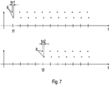
- the measuring points of the first sensor group are shown in the upper diagram and the measuring points of the second sensor group are shown as a function of time t in the lower diagram.
- the respective upper measuring series shows the measuring points of the respective first sensor (2.1, 3.1) of the respective sensor group and the lower measuring series shows the respective measuring points of the respective second sensor (2.2, 3.2) of the respective sensor group.
- the speed sensor preferably detects the speed v of the vehicle 1.
- the first and the second sensor (2.1, 2.2) of the first sensor group detect the reinforcing rod 7 offset in time by t ⁇ 1.
- the first and the second sensor (3.1, 3.2) of the second sensor group detect the reinforcing rod 7 offset in time by t ⁇ 2.
- Each sensor group preferably has a multiplicity of sensors (2.1, 2.2, 3.1, 3.2) which are each arranged on a respective reference line 6.
- sensors 2.1, 2.2, 3.1, 3.2
- signals from other reinforcing bars that cross the reinforcing bar 7 can be determined.
- a sensor that is permanent a reinforcing bar crossing the reinforcing bar 7 is detected, not taken into account in the calculation of the angles ⁇ 1 and ⁇ 2.
- the vehicle 1 For the further application that the vehicle 1 should repeatedly drive the same route, the vehicle 1 carries out a reference run at constant speed and determines measurement points along the entire route using one of the sensors (2.1, 2.2, 3.1, 3.2). A reference profile is determined by means of the measuring points of the reference run. The reference profile indicates an intensity of the signal from the reinforcement for each position on the route.
- the distances between the reinforcing bars 7 can be determined from the intensity maxima of the reference profile.
- the speed of the vehicle 1 can be determined from the time between two intensity maxima instead of by means of the speed sensor.
- the position of the vehicle 1 on the route is preferably also determined.
- measuring points of a profile section are determined by means of the sensor (2.1, 2.2, 3.1, 3.2) which was used during the reference run.
- This profile section is compared with the reference profile by the evaluation means 4, in particular by means of a correlation method. If the profile section clearly matches a section of the reference profile, then each measuring point of the profile section can be clearly assigned to a position on the route.
- the current position of the vehicle 1 is determined by comparing a current measurement point with the profile section and the assigned section of the reference profile.
Landscapes
- Engineering & Computer Science (AREA)
- Physics & Mathematics (AREA)
- Automation & Control Theory (AREA)
- Remote Sensing (AREA)
- Radar, Positioning & Navigation (AREA)
- Aviation & Aerospace Engineering (AREA)
- General Physics & Mathematics (AREA)
- Mathematical Physics (AREA)
- Mechanical Engineering (AREA)
- Transportation (AREA)
- Electromagnetism (AREA)
- Control Of Position, Course, Altitude, Or Attitude Of Moving Bodies (AREA)
- Length Measuring Devices With Unspecified Measuring Means (AREA)
- Radar Systems Or Details Thereof (AREA)
- Navigation (AREA)
Description
Die Erfindung betrifft ein System und ein Verfahren zum Betreiben eines Fahrzeugs.The invention relates to a system and a method for operating a vehicle.
Aus der
Aus der
Aus der
Aus derFrom the
Der Erfindung liegt daher die Aufgabe zugrunde, ein System zur Bestimmung der Fahrtrichtung eines Fahrzeugs weiterzubilden, wobei der Umweltschutz verbessert werden soll.The invention is therefore based on the object of developing a system for determining the direction of travel of a vehicle, with the aim of improving environmental protection.
Erfindungsgemäß wird die Aufgabe bei dem System zur Bestimmung der Fahrtrichtung eines Fahrzeugs nach den in Anspruch 8 angegebenen Merkmalen und bei dem Verfahren nach den in Anspruch 1 angegebenen Merkmalen gelöst.According to the invention, the object is achieved in the system for determining the direction of travel of a vehicle according to the features specified in
Wichtige Merkmale der Erfindung bei dem Verfahren zum Betreiben eines Fahrzeugs, insbesondere zur Bestimmung der Fahrtrichtung des Fahrzeugs, insbesondere mittels eines Systems zur Bestimmung der Fahrtrichtung eines Fahrzeugs wie zuvor beschrieben beziehungsweise nach mindestens einem der auf das System bezogenen Ansprüche, wobei das Fahrzeug auf einem Betonboden verfahrbar angeordnet ist, wobei der Betonboden zumindest einen Armierungsstab aufweist,
wobei das Fahrzeug zumindest einen ersten Sensor und einen zweiten Sensor einer ersten Sensorgruppe aufweist, die entlang einer ersten Referenzlinie um einen Abstand a1 beabstandet voneinander angeordnet sind,
sind, dass das Fahrzeug mit einer Geschwindigkeit v über den Armierungsstab fährt,
wobei der erste Sensor den Armierungsstab zu einem ersten Zeitpunkt t1 erfasst,
wobei der zweite Sensor den Armierungsstab zu einem zweiten Zeitpunkt t2, insbesondere zeitlich nach dem ersten Zeitpunkt t1, erfasst,
wobei die Zeitdifferenz tα1 zwischen dem ersten Zeitpunkt t1 und dem zweiten Zeitpunkt t2 bestimmt wird,
wobei aus der Zeitdifferenz tα1, der Geschwindigkeit v und dem Abstand a1 ein Winkel α1 bestimmt wird, der den Winkel zwischen der Fahrtrichtung des Fahrzeugs und der Erstreckungsrichtung des Armierungsstabes zum ersten und/oder zweiten Zeitpunkt angibt.Important features of the invention in the method for operating a vehicle, in particular for determining the direction of travel of the vehicle, in particular by means of a system for determining the direction of travel of a vehicle as described above or according to at least one of the claims related to the system, wherein the vehicle is on a concrete floor is arranged movably, wherein the concrete floor has at least one reinforcing rod,
wherein the vehicle has at least a first sensor and a second sensor of a first sensor group, which are arranged along a first reference line at a distance a 1 from one another,
are that the vehicle drives over the reinforcement bar at a speed v,
wherein the first sensor detects the reinforcement rod at a first point in time t 1 ,
wherein the second sensor detects the reinforcing rod at a second point in time t 2 , in particular after the first point in time t 1 ,
where the time difference t α1 between the first point in time t 1 and the second point in time t 2 is determined,
where from the time difference t α1 , the speed v and the distance a 1, an angle α 1 is determined, which indicates the angle between the direction of travel of the vehicle and the direction of extension of the reinforcing rod at the first and / or second point in time.
Diese Bestimmung wird erfindungsgemäß nur vorgenommen, wenn die Sensoren den Armierungsstab auch erfassen, also ihn queren, und somit entsprechende Signale erzeugen. Ansonsten gilt Die Fahrtrichtung als parallel zum Armierungsstab gilt oder ihr ist ein vorgegebener Richtungswinkelwert zugeordnet.According to the invention, this determination is only made if the sensors also detect the reinforcing rod, that is to say cross it, and thus generate corresponding signals. Otherwise, the direction of travel is considered to be parallel to the reinforcement rod or a specified direction angle value is assigned to it.
Von Vorteil ist dabei, dass die Fahrtrichtung des Fahrzeugs relativ zu dem Armierungsstab bestimmbar ist. Vorteilhafterweise weist der Betonboden einer Fahrbahn, insbesondere einer Fabrikhalle, üblicherweise Armierungsstäbe auf. Somit ist lediglich das Fahrzeug mit Sensoren und einem Auswertemittel zur Auswertung der Signale des Armierungsstabes auszurüsten. Die Bestimmung der Fahrtrichtung ist also mit geringem Materialaufwand ausführbar. Der Umweltschutz ist verbessert.The advantage here is that the direction of travel of the vehicle can be determined relative to the reinforcing rod. Advantageously, the concrete floor of a roadway, in particular a factory hall, usually has reinforcing bars. Thus, only the vehicle needs to be equipped with sensors and an evaluation means for evaluating the signals from the reinforcing rod. The determination of the direction of travel can therefore be carried out with little material expenditure. Environmental protection is improved.
Bei einer vorteilhaften Ausgestaltung fährt das Fahrzeug mit konstanter Geschwindigkeit v, wobei der Winkel α1 folgendermaßen berechnet wird: 
Bei einer vorteilhaften Ausgestaltung weist das Fahrzeug eine zweite Sensorgruppe auf, wobei die zweite Sensorgruppe zumindest zwei Sensoren aufweist, die entlang einer zweiten Referenzlinie um einen Abstand a2 beabstandet voneinander angeordnet sind, wobei die erste Sensorgruppe und die zweite Sensorgruppe derart angeordnet sind, dass die erste Referenzlinie und die zweite Referenzlinie parallel zueinander angeordnet sind und um den Abstand x beabstandet voneinander sind, wobei ein erster Sensor der zweiten Sensorgruppe den Armierungsstab zu einem dritten Zeitpunkt t3 zeitlich nach dem zweiten Zeitpunkt t2 erfasst, wobei ein zweiter Sensor der zweiten Sensorgruppe den Armierungsstab zu einem vierten Zeitpunkt t4, insbesondere zeitlich nach dem dritten Zeitpunkt t3, erfasst, wobei die Zeitdifferenz tα2 zwischen dem dritten Zeitpunkt t3 und dem vierten Zeitpunkt t4 bestimmt wird, wobei aus der Zeitdifferenz tα2 , der Geschwindigkeit v und dem Abstand a2 ein Winkel α2 bestimmt wird, der den Winkel zwischen der Fahrtrichtung des Fahrzeugs und der Erstreckungsrichtung des Armierungsstabes zum dritten und/oder vierten Zeitpunkt angibt. Von Vorteil ist dabei, dass eine Richtungsabweichung bei der Fahrtrichtung erkennbar ist, indem die mit den Sensoren der ersten Sensorgruppe bestimmte Fahrtrichtung und die mit den Sensoren der zweiten Sensorgruppe bestimmte Fahrtrichtung verglichen wird. Das Fahrzeug ist dadurch wieder auf die gewünschte Fahrtrichtung korrigierbar.In an advantageous embodiment, the vehicle has a second sensor group, the second sensor group having at least two sensors which are arranged along a second reference line at a distance a 2 from one another, the first sensor group and the second sensor group being arranged such that the The first reference line and the second reference line are arranged parallel to one another and are spaced apart from one another by the distance x, a first sensor of the second sensor group detecting the reinforcing rod at a third point in time t 3 after the second point in time t 2 , with a second sensor of the second sensor group the reinforcing rod at a fourth point in time t 4 , in particular after the third point in time t 3 , the time difference t α2 being determined between the third point in time t 3 and the fourth point in time t 4 , the time difference t α2 , the speed v and the distance a 2 determine an angle α 2 mt, which indicates the angle between the direction of travel of the vehicle and the direction of extension of the reinforcing rod at the third and / or fourth point in time. The advantage here is that a directional deviation in the direction of travel can be identified by comparing the direction of travel determined with the sensors of the first sensor group and the direction of travel determined with the sensors of the second sensor group. The vehicle can then be corrected to the desired direction of travel again.
Bei einer vorteilhaften Ausgestaltung fährt das Fahrzeug mit konstanter Geschwindigkeit v, wobei der Winkel α2 folgendermaßen berechnet wird: 
Bei einer vorteilhaften Ausgestaltung verwendet das Fahrzeug die Differenz der Winkel α1 und α2 zur Steuerung des Fahrzeugs, wobei die Differenz der Winkel α1 und α2 eine Richtungsänderung der Fahrtrichtung während der zurückgelegten Strecke x angibt, also einen Lenkwinkel, insbesondere
- wobei mittels eines Reglers des Fahrzeugs der so bestimmte Lenkwinkel auf einen Sollwert hin geregelt wird, indem ein Lenkantrieb des Fahrzeugs entsprechend gestellt wird,
und/oder - der bestimmte Lenkwinkel auf unzulässige Überschreitung eines vorgebbaren Grenzwertes überwacht wird.
Von Vorteil dabei ist also, dass der Lenkwinkel auf unzulässig große Werte hin überwacht wird und/oder dass er zur Lenkung des Fahrzeugs verwendbar ist.
- wherein the steering angle determined in this way is regulated to a setpoint value by means of a controller of the vehicle by setting a steering drive of the vehicle accordingly,
and or - the specific steering angle is monitored for impermissible exceeding of a predefinable limit value.
The advantage here is that the steering angle is monitored for impermissibly large values and / or that it can be used to steer the vehicle.
Bei einer vorteilhaften Ausgestaltung wird die Zeitspanne Δt mittels der Geschwindigkeit v und des Abstands x zwischen den Sensorgruppen folgendermaßen berechnet: 
![]()
insbesondere wobei der Schwellwert betragsmäßig weniger als ein Fünftel oder weniger als ein Zwanzigstel der Zeitspanne Δt beträgt.In an advantageous embodiment, the time period Δt is calculated using the speed v and the distance x between the sensor groups as follows:![]()
in particular, the threshold value being less than a fifth or less than a twentieth of the time period Δt in terms of amount.
Von Vorteil ist dabei, dass ein Detektionssignal, das mittels eines Sensors der zweiten Sensorgruppe erfasst wurde, in einfacher Art und Weise dem Detektionssignal zuordenbar ist, das von einem Sensor der ersten Sensorgruppe erfasst wurde, indem die Zeit zwischen den beiden Signalen mit der Zeitspanne Δt verglichen wird.The advantage here is that a detection signal that was recorded by means of a sensor of the second sensor group can be easily assigned to the detection signal that was recorded by a sensor of the first sensor group by dividing the time between the two signals with the time interval Δt is compared.
Insbesondere ist bei einer Anlage mit einer Vielzahl von voneinander beabstandeten, parallel angeordneten Armierungsstäben mittels geeigneter Vorgabe des Schwellwertes verhinderbar, dass die vordere und die hintere Sensorgruppe Signale nicht denselben Armierungsstab detektieren.In particular, in the case of a system with a large number of spaced-apart, parallel-arranged reinforcing bars, by means of suitable specification of the threshold value, it can be prevented that the front and rear sensor group signals do not detect the same reinforcing bar.
Bei einer vorteilhaften Ausgestaltung werden zur Bestimmung der Geschwindigkeit des Fahrzeugs entlang einer Fahrstrecke die folgenden zeitlich aufeinander folgenden Verfahrensschritte ausgeführt:
- wobei in einem ersten Verfahrensschritt das Fahrzeug eine Referenzfahrt mit konstanter Geschwindigkeit entlang der Fahrstrecke ausführt, wobei einer der Sensoren entlang der Fahrstrecke Messpunkte aufnimmt, wobei jeder Messpunkt einer Position auf der Fahrstrecke ein Signal einer Anordnung von Armierungsstäben im Betonboden zuordnet,
- wobei in einem zweiten Verfahrensschritt aus den während der Referenzfahrt ermittelten Messpunkten ein Referenzprofil der Fahrstrecke bestimmt wird,
- wobei in einem dritten Verfahrensschritt das Fahrzeug entlang der Fahrstrecke fährt und mittels des während der Referenzfahrt verwendeten Sensors weitere Messpunkte aufnimmt,
- wobei in einem vierten Verfahrensschritt aus den weiteren Messpunkten ein Profilabschnitt bestimmt wird,
- wobei in einem fünften Verfahrensschritt der Profilabschnitt einem Abschnitt des Referenzprofils eindeutig zugeordnet wird, insbesondere mittels eines Korrelationsverfahrens,
- wobei in einem sechsten Verfahrensschritt mittels des dem Referenzprofil zugeordneten Profilabschnitts dem Fahrzeug Positionen auf der Fahrstrecke eindeutig zugeordnet werden,
- wobei in einem siebten Verfahrensschritt aus den Positionen auf der Fahrstrecke und der Zeitspanne zwischen den Messpunkten dieser Positionen die Geschwindigkeit des Fahrzeugs (1) bestimmt wird.
- In a first method step, the vehicle carries out a reference run at constant speed along the route, one of the sensors recording measurement points along the route, each measuring point assigning a signal to an arrangement of reinforcing bars in the concrete floor to a position on the route,
- in a second method step, a reference profile of the route is determined from the measurement points determined during the reference run,
- wherein in a third method step the vehicle drives along the route and records further measurement points by means of the sensor used during the reference drive,
- in a fourth method step, a profile section is determined from the further measuring points,
- wherein in a fifth method step the profile section is clearly assigned to a section of the reference profile, in particular by means of a correlation method,
- wherein in a sixth method step positions on the route are clearly assigned to the vehicle by means of the profile section assigned to the reference profile,
- wherein in a seventh method step the speed of the vehicle (1) is determined from the positions on the route and the time span between the measuring points of these positions.
Von Vorteil ist dabei, dass die Geschwindigkeit des Fahrzeugs redundant bestimmbar ist mittels des Geschwindigkeitssensors und des Sensors. Somit ist die Messgenauigkeit verbessert.The advantage here is that the speed of the vehicle can be determined redundantly by means of the speed sensor and the sensor. Thus, the measurement accuracy is improved.
Vorteilhafterweise ist der Geschwindigkeitssensor verzichtbar. Somit ist der Umweltschutz verbessert.The speed sensor can advantageously be dispensed with. Thus, environmental protection is improved.
Wichtige Merkmale der Erfindung bei dem System zur Bestimmung der Fahrtrichtung eines Fahrzeugs, sind dass
das System das Fahrzeug und einen Betonboden, aufweisend zumindest einen Armierungsstab, aufweist,
wobei das Fahrzeug verfahrbar auf dem Betonboden angeordnet ist,
wobei das Fahrzeug ein Auswertemittel und eine erste Sensorgruppe, aufweisend zumindest zwei Sensoren, aufweist,
wobei die Sensoren entlang einer ersten Referenzlinie beabstandet voneinander angeordnet sind,
wobei die Sensoren zur Erfassung des Armierungsstabes eingerichtet sind,
wobei das Auswertemittel mit den Sensoren verbunden ist und zur Bestimmung der Fahrtrichtung aus den Signalen der Sensoren eingerichtet ist.Important features of the invention in the system for determining the direction of travel of a vehicle are that
the system comprises the vehicle and a concrete floor having at least one reinforcement bar,
wherein the vehicle is movably arranged on the concrete floor,
wherein the vehicle has an evaluation means and a first sensor group having at least two sensors,
wherein the sensors are arranged at a distance from one another along a first reference line,
where the sensors are set up to detect the reinforcement bar,
wherein the evaluation means is connected to the sensors and is set up to determine the direction of travel from the signals from the sensors.
Von Vorteil ist dabei, dass die Fahrtrichtung des Fahrzeugs relativ zu dem Armierungsstab bestimmbar ist. Vorteilhafterweise weist der Betonboden einer Fahrbahn, insbesondere einer Fabrikhalle, üblicherweise Armierungsstäbe auf. Somit ist lediglich das Fahrzeug mit den Sensoren und dem Auswertemittel auszurüsten. Die Bestimmung der Fahrtrichtung ist also mit geringem Materialaufwand ausführbar. Der Umweltschutz ist verbessert.The advantage here is that the direction of travel of the vehicle can be determined relative to the reinforcing rod. Advantageously, the concrete floor of a roadway, in particular a factory hall, usually has reinforcing bars. Thus, only the vehicle needs to be equipped with the sensors and the evaluation means. The determination of the direction of travel can therefore be carried out with little material expenditure. Environmental protection is improved.
Bei einer vorteilhaften Ausgestaltung weist das Fahrzeug eine zweite Sensorgruppe, aufweisend zumindest zwei Sensoren, auf, wobei die Sensoren der zweiten Sensorgruppe entlang einer zweiten Referenzlinie beabstandet voneinander angeordnet sind, wobei die erste Referenzlinie und die zweite Referenzlinie beabstandet voneinander und parallel zueinander angeordnet sind, wobei die Sensoren der zweiten Sensorgruppe zur Erfassung des Armierungsstabes eingerichtet sind, wobei das Auswertemittel mit den Sensoren der zweiten Sensorgruppe verbunden ist und zur Bestimmung der Fahrtrichtung aus den Signalen der Sensoren der zweiten Sensorgruppe eingerichtet ist. Von Vorteil ist dabei, dass eine Richtungsabweichung bei der Fahrtrichtung erkennbar ist, indem die mit den Sensoren der ersten Sensorgruppe bestimmte Fahrtrichtung und die mit den Sensoren der zweiten Sensorgruppe bestimmte Fahrtrichtung verglichen werden. Das Fahrzeug ist dadurch wieder auf die gewünschte Fahrtrichtung korrigierbar.In an advantageous embodiment, the vehicle has a second sensor group, having at least two sensors, the sensors of the second sensor group being arranged along a second reference line at a distance from one another, the first reference line and the second reference line being arranged at a distance from one another and parallel to one another, wherein the sensors of the second sensor group are set up to detect the reinforcement bar, the evaluation means being connected to the sensors of the second sensor group and being set up to determine the direction of travel from the signals from the sensors of the second sensor group. The advantage here is that a directional deviation in the direction of travel can be identified by comparing the direction of travel determined by the sensors of the first sensor group and the direction of travel determined by the sensors of the second sensor group. The vehicle can then be corrected to the desired direction of travel again.
Bei einer vorteilhaften Ausgestaltung sind die Sensoren an einem Fahrzeugboden des Fahrzeugs angeordnet. Von Vorteil ist dabei, dass der Abstand zwischen dem Fahrzeug und dem Betonboden kleiner ist, als bei einer Anordnung des Sensors an anderen Positionen auf dem Fahrzeug. Somit ist ein gutes Signal-Rausch-Verhältnis bei der Bestimmung des Signals von dem Armierungsstab erreichbar. Vorteilhafterweise ist zwischen dem Sensor und dem Betonboden ausschließlich Luft angeordnet.In an advantageous embodiment, the sensors are arranged on a vehicle floor of the vehicle. The advantage here is that the distance between the vehicle and the concrete floor is smaller than when the sensor is arranged at other positions on the vehicle. A good signal-to-noise ratio can thus be achieved when determining the signal from the reinforcement rod. Advantageously, only air is arranged between the sensor and the concrete floor.
Bei einer vorteilhaften Ausgestaltung sind die Sensoren Radarsensoren und/oder induktive Sensoren, die dazu eingerichtet sind, die Dicke und/oder die Dichte und/oder die Tiefe des Armierungsstabes im Betonboden zu bestimmen. Von Vorteil ist dabei, dass mittels des Sensors ein charakteristisches Referenzprofil der Armierung entlang einer Fahrstrecke bestimmbar ist.In an advantageous embodiment, the sensors are radar sensors and / or inductive sensors which are set up to determine the thickness and / or the density and / or the depth of the reinforcement bar in the concrete floor. The advantage here is that a characteristic reference profile of the reinforcement along a route can be determined by means of the sensor.
Bei einer vorteilhaften Ausgestaltung weist das Fahrzeug eine Fahrzeugsteuerung auf, insbesondere wobei das Fahrzeug als fahrerloses Transportfahrzeug ausgeführt ist, wobei die Fahrzeugsteuerung mit dem Auswertemittel verbunden ist. Von Vorteil ist dabei, dass die Signale des Armierungsstabes von dem Fahrzeug auswertbar sind und daraus die Fahrtrichtung des Fahrzeugs von dem Fahrzeug selbst bestimmbar ist und diese Fahrtrichtung zur autonomen Steuerung des Fahrzeugs verwendbar ist.In an advantageous embodiment, the vehicle has a vehicle controller, in particular the vehicle being designed as a driverless transport vehicle, the vehicle controller being connected to the evaluation means. The advantage here is that the signals from the reinforcement bar can be evaluated by the vehicle and the direction of travel of the vehicle can be determined therefrom by the vehicle itself and this direction of travel can be used for autonomous control of the vehicle.
Bei einer vorteilhaften Ausgestaltung weist das Auswertemittel eine Recheneinheit auf, die zur Berechnung von trigonometrischen Funktionen eingerichtet ist. Von Vorteil ist dabei, dass die Auswertung der Signale des Armierungsstabes in einfacher Art und Weise von dem Fahrzeug mittels des Auswertemittels ausführbar ist.In an advantageous embodiment, the evaluation means has a computing unit which is set up to calculate trigonometric functions. The advantage here is that the evaluation of the signals from the reinforcing rod can be carried out in a simple manner by the vehicle by means of the evaluation means.
Bei einer vorteilhaften Ausgestaltung weist das Auswertemittel ein Zeitmessmittel auf, das zur Bestimmung der Zeit zwischen zwei aufeinander folgenden Zeitpunkten der Erfassung des Armierungsstabs eingerichtet ist. Von Vorteil ist dabei, dass der Armierungsstab, der mittels eines Sensors der zweiten Sensorgruppe erfasst wurde, in einfacher Art und Weise demjenigen Detektionssignal zuordenbar ist, das von einem Sensor der ersten Sensorgruppe erfasst wurde, in dem die Zeit zwischen den beiden Signalen mit der Zeitspanne Δt verglichen wird, die mittels des Abstands der Sensorgruppen und der Geschwindigkeit des Fahrzeugs bestimmbar ist.In an advantageous embodiment, the evaluation means has a time measuring means which is set up to determine the time between two successive points in time when the reinforcing rod is detected. The advantage here is that the reinforcing rod, which was detected by means of a sensor of the second sensor group, can be easily assigned to that detection signal that was detected by a sensor of the first sensor group in which the time between the two signals with the time span Δt is compared, which can be determined by means of the distance between the sensor groups and the speed of the vehicle.
Bei einer vorteilhaften Ausgestaltung weist das System einen Geschwindigkeitssensor auf zur Bestimmung der Geschwindigkeit v des Fahrzeugs in Fahrtrichtung. Von Vorteil ist dabei, dass Geschwindigkeitsabweichungen in einfacher Art und Weise detektierbar sind.In an advantageous embodiment, the system has a speed sensor for determining the speed v of the vehicle in the direction of travel. The advantage here is that speed deviations can be detected in a simple manner.
Bei einer vorteilhaften Ausgestaltung weist der Betonboden eine Vielzahl von Armierungsstäben auf. Von Vorteil ist dabei, dass mittels der Armierungsstäbe an verschiedenen Positionen auf dem Betonboden die Fahrtrichtung des Fahrzeugs bestimmbar ist.In an advantageous embodiment, the concrete floor has a large number of reinforcing bars. The advantage here is that the direction of travel of the vehicle can be determined by means of the reinforcing bars at different positions on the concrete floor.
Vorteilhafterweise sind die Armierungsstäbe derart in dem Betonboden verteilt anordenbar, dass das Fahrzeug jederzeit einen Armierungsstab mit einem Sensor der ersten Sensorgruppe und/oder einem Sensor der zweiten Sensorgruppe detektiert.The reinforcing bars can advantageously be arranged distributed in the concrete floor in such a way that the vehicle detects a reinforcing bar with a sensor of the first sensor group and / or a sensor of the second sensor group at any time.
Zur Unterscheidung der Armierungsstäbe wird die Zeitspanne Δt berechnet, die zwischen dem Zeitpunkt, zu dem ein Sensor der ersten Sensorgruppe einen Armierungsstab detektiert, und dem Zeitpunkt, zu dem ein Sensor der zweiten Sensorgruppe denselben Armierungsstab detektiert, vergeht.To distinguish between the reinforcement bars, the time interval Δt is calculated which elapses between the point in time at which a sensor of the first sensor group detects a reinforcement bar and the point in time at which a sensor of the second sensor group detects the same reinforcement bar.
Bei einer vorteilhaften Ausgestaltung sind die Armierungsstäbe parallel zueinander und/oder als Gitter angeordnet. Von Vorteil ist dabei, dass zwei Sensoren für jede Sensorgruppe ausreichend sind, um die Fahrtrichtung des Fahrzeugs zu bestimmen.In an advantageous embodiment, the reinforcing bars are arranged parallel to one another and / or as a grid. The advantage here is that two sensors are sufficient for each sensor group to determine the direction of travel of the vehicle.
Bei einer vorteilhaften Ausgestaltung weist jede Sensorgruppe eine Vielzahl von Sensoren auf, wobei das Auswertemittel zur Auswertung der Signale der Sensoren der ersten und zweiten Sensorgruppe eingerichtet ist. Von Vorteil ist dabei, dass die Messgenauigkeit verbessert ist. Der Winkel zu dem Armierungsstab ist mittels verschiedenen Sensorpaaren einer Sensorgruppe berechenbar und ein Mittelwert der Winkel ist bestimmbar. Somit ist die Messgenauigkeit verbessert.In an advantageous embodiment, each sensor group has a multiplicity of sensors, the evaluation means being set up to evaluate the signals from the sensors of the first and second sensor groups. The advantage here is that the measurement accuracy is improved. The angle to the reinforcement bar can be calculated by means of different sensor pairs of a sensor group and a mean value of the angles can be determined. Thus, the measurement accuracy is improved.
Bei einer vorteilhaften Ausgestaltung ist das Auswertemittel zur Auswahl von einzelnen Sensoren aus einer Sensorgruppe für die Bestimmung der Fahrtrichtung des Fahrzeugs eingerichtet. Von Vorteil ist dabei, dass ein Sensor, der permanent das Signal eines den Armierungsstab kreuzenden Armierungsstabes empfängt, von dem Auswertemittel ignorierbar ist. Somit ist die Messgenauigkeit verbessert.In an advantageous embodiment, the evaluation means is set up to select individual sensors from a sensor group for determining the direction of travel of the vehicle. The advantage here is that a sensor which permanently receives the signal from a reinforcing rod crossing the reinforcing rod can be ignored by the evaluation means. Thus, the measurement accuracy is improved.
Weitere Vorteile ergeben sich aus den Unteransprüchen. Die Erfindung ist nicht auf die Merkmalskombination der Ansprüche beschränkt. Für den Fachmann ergeben sich weitere sinnvolle Kombinationsmöglichkeiten von Ansprüchen und/oder einzelnen Anspruchsmerkmalen und/oder Merkmalen der Beschreibung und/oder der Figuren, insbesondere aus der Aufgabenstellung und/oder der sich durch Vergleich mit dem Stand der Technik stellenden Aufgabe.Further advantages result from the subclaims. The invention is not restricted to the combination of features of the claims. For the person skilled in the art, there are further meaningful possible combinations of claims and / or individual claim features and / or features of the description and / or the figures, in particular from the task and / or the task posed by comparison with the prior art.
Die Erfindung wird nun anhand von Abbildungen näher erläutert:
- In
der Figur 1 ist ein Fahrzeug 1 eines erfindungsgemäßen Systems zur Bestimmung der Fahrtrichtung eines Fahrzeugs in Draufsicht schematisch gezeichnet. -
Figur 2 zeigt zwei Sensoren (2.1, 2.2) einer Sensorgruppe des Fahrzeugs 1 in Draufsicht, die auf einer Referenzlinie 6 angeordnet sind. - In
Figur 3 ist ein Armierungsstab 7 einer Armierung eines Betonbodens des erfindungsgemäßen Systems und dessen Lage relativ zu der Referenzlinie 6 schematisch gezeichnet. - In
Figur 4wobei das Fahrzeug 1auf dem Armierungsstäbe 7 aufweisenden Betonboden inFahrtrichtung 9 fährt, wobei der Betonboden transparent dargestellt ist. -
Figur 5 - In
Figur 6wobei das Fahrzeug 1auf dem Armierungsstäbe 7 aufweisenden Betonboden inFahrtrichtung 9 fährt, wobei der Betonboden transparent dargestellt ist. -
Figur 7 - In
Figur 8
- In the
Figure 1 avehicle 1 of a system according to the invention for determining the direction of travel of a vehicle is shown schematically in a top view. -
Figure 2 shows two sensors (2.1, 2.2) of a sensor group of thevehicle 1 in a top view, which are arranged on areference line 6. - In
Figure 3 areinforcement bar 7 of a reinforcement of a concrete floor of the system according to the invention and its position relative to thereference line 6 is shown schematically. - In
Figure 4 a first example of application of the system according to the invention is shown schematically, thevehicle 1 traveling in the direction oftravel 9 on the concrete floor having reinforcingbars 7, the concrete floor being shown as transparent. -
Figure 5 shows measuring points of the sensors (2.1, 2.2, 3.1, 3.2) in the first application example as a function of time t. - In
Figure 6 a second example of application of the system according to the invention is shown schematically, thevehicle 1 traveling on the concrete floor having reinforcingbars 7 in the direction oftravel 9, the concrete floor being shown transparent. -
Figure 7 shows measuring points of the sensors (2.1, 2.2, 3.1, 3.2) in the first application example as a function of time t. - In
Figure 8 the distance b covered in a time t α1 and the distance a 1 between two sensors (2.1, 2.2) of a first sensor group and a resulting angle α 1 are drawn.
Das in
Sensoren (2.1, 2.2, 3.1, 3.2) aufweist, die entlang einer jeweiligen Referenzlinie 6 beabstandet voneinander angeordnet sind. Die Sensoren (2.1, 2.2, 3.1, 3.2) sind derart am Fahrzeug 1 angeordnet, dass die Referenzlinien der ersten und zweiten Sensorgruppe jeweils parallel angeordnet sind. Die Sensorgruppen sind um einen Abstand x beabstandet voneinander angeordnet.Sensors (2.1, 2.2, 3.1, 3.2) which are arranged along a
Vorzugsweise sind die Sensoren (2.1, 2.2, 3.1, 3.2) als induktive Sensoren und/oder Radarsensoren ausgeführt. Vorzugsweise sind die Sensoren (2.1, 2.2, 3.1, 3.2) am Fahrzeugboden des Fahrzeugs 1 angeordnet und zum Betonboden hin ausgerichtet.The sensors (2.1, 2.2, 3.1, 3.2) are preferably designed as inductive sensors and / or radar sensors. The sensors (2.1, 2.2, 3.1, 3.2) are preferably arranged on the vehicle floor of the
Vorteilhafterweise sind die Referenzlinien der ersten und zweiten Sensorgruppe jeweils quer zur Fahrtrichtung 9 des Fahrzeugs 1 angeordnet.Advantageously, the reference lines of the first and second sensor groups are each arranged transversely to the direction of
Das Fahrzeug 1 weist ein Auswertemittel 4 auf, wobei das Auswertemittel 4 mit den Sensoren (2.1, 2.2, 3.1, 3.2) der Sensorgruppen verbunden ist, insbesondere mittels eines Verbindungsmittels 5. Das Auswertemittel 4 ist zur Auswertung der Signale von den Sensoren (2.1, 2.2, 3.1, 3.2) eingerichtet. Vorzugsweise weist das Auswertemittel 4 eine Recheneinheit auf, die zur Berechnung von trigonometrischen Funktionen eingerichtet ist.The
Das Fahrzeug 1 weist einen Geschwindigkeitssensor auf, wobei das Auswertemittel 4 mit dem Geschwindigkeitssensor verbunden ist. Das Auswertemittel 4 ist zur Auswertung der Signale von dem Geschwindigkeitssensor eingerichtet.The
Das erfindungsgemäße System zur Bestimmung der Fahrtrichtung eines Fahrzeugs weist das Fahrzeug 1 und den Betonboden auf, wobei das Fahrzeug 1 auf dem Betonboden verfahrbar ist.The system according to the invention for determining the direction of travel of a vehicle has the
Der Betonboden weist die Armierung auf zur Bewehrung des Betonbodens. Die Armierung ist metallisch und weist eine größere Duktilität auf als Beton. Vorzugsweise ist die Armierung aus Stahl, insbesondere Betonstahl, ausgeführt. Als Armierung sind Betonstabstahl und/oder Betonstahlmatten und/oder Betonstahl in Ringen und/oder Bewehrungsdraht und/oder Gitterträger verwendbar. Vorteilhafterweise weist die Armierung Armierungsstäbe 7 auf, die zumindest teilweise geradlinig ausgeführt sind.The concrete floor has the reinforcement for reinforcing the concrete floor. The reinforcement is metallic and has a greater ductility than concrete. The reinforcement is preferably made of steel, in particular reinforcing steel. Reinforcing bars and / or welded wire meshes and / or reinforcing steel in rings and / or reinforcing wire and / or lattice girders can be used. The reinforcement advantageously has reinforcing
Die Armierung im Betonboden ist mittels eines Radarsensors und/oder mittels eines induktiven Sensors detektierbar. Die Intensität I des Signals von der Armierung ist dabei abhängig von der Tiefe der Armierung im Betonboden und von der Dicke der Armierung am Ort der Messung. Beispielsweise bewirkt ein Knotenpunkt von zwei Armierungsstäben 7 ein größeres Signal als ein einzelner Armierungsstab 7.The reinforcement in the concrete floor can be detected by means of a radar sensor and / or by means of an inductive sensor. The intensity I of the signal from the reinforcement is dependent on the depth of the reinforcement in the concrete floor and on the thickness of the reinforcement at the location of the measurement. For example, a junction of two reinforcing
Wie in
Solange trotz nicht verschwindender Fahrgeschwindigkeit des Fahrzeugs 1 keine Erfassung eines Armierungsstabs 7 stattfinden, gilt die Fahrtrichtung als parallel zum Armierungsstab 7 oder ist einem anderen vorgegebenen Anfangs-Richtungswinkelwert zugeordnet. Wenn jedoch mittels der Sensoren ein Armierungsstab erfasst wird und somit Signale von den Sensoren erzeugt werden, wird eine Bestimmung des Fahrtrichtungs-Winkels ausgeführt:
In den
In the
In
Das Fahrzeug 1 fährt in Fahrtrichtung 9 auf dem Betonboden über die Armierungsstäbe 7. Vorteilhafterweise fährt das Fahrzeug mit konstanter Geschwindigkeit v. The
Zu einem ersten Zeitpunkt t1 detektieren die Sensoren (2.1, 2.2) der ersten Sensorgruppe zeitgleich einen Armierungsstab 7. Zu einem dritten Zeitpunkt t3 detektieren die Sensoren (3.1, 3.2) der zweiten Sensorgruppe zeitgleich den Armierungsstab 7.At a first point in time t 1, the sensors (2.1, 2.2) of the first sensor group simultaneously detect a reinforcing
Vorzugsweise erfasst der Geschwindigkeitssensor die Geschwindigkeit v des Fahrzeugs 1.The speed sensor preferably detects the speed v of the
Mittels der Geschwindigkeit v und des Abstands x zwischen den Sensorgruppen lässt sich die Zeitspanne Δt = t1 - t3 = x / v bestimmen, die das Fahrzeug 1 benötigt, bis die Sensoren (3.1, 3.2) der zweiten Sensorgruppe den Armierungsstab 7 detektieren, nachdem der Armierungsstab 7 von den Sensoren (2.1, 2.2) der ersten Sensorgruppe detektiert wurde.By means of the speed v and the distance x between the sensor groups, the time span Δt = t 1 - t 3 = x / v can be determined which the
Erfassen die Sensoren (2.1, 2.2) der ersten Sensorgruppe den Armierungsstab 7 gleichzeitig, aber die Sensoren (3.1, 3.2) der zweiten Sensorgruppe erfassen den Armierungsstab 7 zeitversetzt so wurde die Fahrtrichtung 9 des Fahrzeuges 1 während der Zeitspanne Δt verändert.If the sensors (2.1, 2.2) of the first sensor group detect the
Weicht die Zeit t3 von dem mittels Δt berechneten Wert für t3 ab, so wurde die Geschwindigkeit v fehlerhaft bestimmt oder die Geschwindigkeit v wurde während der Zeitspanne Δt verändert.If the time t 3 deviates from the value for t 3 calculated by means of Δt , then the speed v was determined incorrectly or the speed v was changed during the time period Δt .
In den
In
Vorzugsweise erfasst der Geschwindigkeitssensor die Geschwindigkeit v des Fahrzeugs 1.The speed sensor preferably detects the speed v of the
Der erste und der zweite Sensor (2.1, 2.2) der ersten Sensorgruppe detektieren den Armierungsstab 7 um tα1 zeitversetzt. Mittels der Zeitdifferenz tα1, der Geschwindigkeit v und des Abstands a1 zwischen dem ersten Sensor 2.1 und dem zweiten Sensor 2.2 der ersten Sensorgruppe berechnet sich der Winkel α1 zwischen der Referenzlinie 6 der ersten Sensorgruppe und dem Armierungsstab 7 folgendermaßen: 
Dabei ist b1 = v • tα1 die von dem Fahrzeug 1 in dem Zeitdifferenz tα1 zurückgelegte Strecke b1. Here, b 1 = v • t α1 is the distance b 1 covered by the
Der erste und der zweite Sensor (3.1, 3.2) der zweiten Sensorgruppe detektieren den Armierungsstab 7 um tα2 zeitversetzt. Mittels der Zeitdifferenz tα2, der Geschwindigkeit v und des Abstands a2 zwischen dem ersten Sensor 3.1 und dem zweiten Sensor 3.2 der zweiten Sensorgruppe berechnet sich der Winkel α2 zwischen der Referenzlinie 6 der zweiten Sensorgruppe und dem Armierungsstab 7 folgendermaßen: 
Dabei ist b2 = v • tα2 die von dem Fahrzeug 1 in der Zeitdifferenz tα2 zurückgelegte Strecke b2 .Here, b 2 = v • t α2 is the distance b 2 covered by the
Sind α1 und α2 gleich, so ist die Fahrtrichtung 9 des Fahrzeugs relativ zur Armierung in der Zeit Δt unverändert geblieben.If α 1 and α 2 are the same, then the direction of
Sind α1 und α2 ungleich, so ist die Fahrtrichtung 9 des Fahrzeugs relativ zur Armierung in der Zeit Δt verändert worden.If α 1 and α 2 are not equal, then the direction of
Vorzugsweise weist jede Sensorgruppe eine Vielzahl von Sensoren (2.1, 2.2, 3.1, 3.2) auf, die jeweils auf einer jeweiligen Referenzlinie 6 angeordnet sind. Mittels der Vielzahl von Sensoren (2.1, 2.2, 3.1, 3.2) sind Signale von anderen Armierungsstäben, die den Armierungsstab 7 kreuzen, herausmittelbar. Beispielsweise wird ein Sensor, der permanent einen den Armierungsstab 7 kreuzenden Armierungsstab detektiert, bei der Berechnung der Winkel α1 und α2 nicht berücksichtigt.Each sensor group preferably has a multiplicity of sensors (2.1, 2.2, 3.1, 3.2) which are each arranged on a
Für den weiteren Anwendungsfall, dass das Fahrzeug 1 wiederholt die gleiche Fahrstrecke fahren soll, führt das Fahrzeug 1 eine Referenzfahrt mit konstanter Geschwindigkeit durch und bestimmt entlang der gesamten Fahrstrecke Messpunkte mittels eines der Sensoren (2.1, 2.2, 3.1, 3.2). Mittels der Messpunkte der Referenzfahrt wird ein Referenzprofil bestimmt. Das Referenzprofil gibt für jede Position auf der Fahrstrecke eine Intensität des Signals von der Armierung an.For the further application that the
Aus den Intensitätsmaxima des Referenzprofils sind die Abstände zwischen den Armierungsstäben 7 bestimmbar. Somit ist während der Fahrt die Geschwindigkeit des Fahrzeugs 1 statt mittels des Geschwindigkeitssensors aus der Zeit zwischen zwei Intensitätsmaxima bestimmbar. Vorzugsweise wird dazu auch die Position des Fahrzeugs 1 auf der Fahrstrecke bestimmt.The distances between the reinforcing
Zur Bestimmung der Position des Fahrzeugs 1 auf der Fahrstrecke werden mittels des Sensors (2.1, 2.2, 3.1, 3.2), der während der Referenzfahrt benutzt wurde, Messpunkte eines Profilabschnitts bestimmt. Dieser Profilabschnitt wird von dem Auswertemittel 4 mit dem Referenzprofil verglichen, insbesondere mittels eines Korrelationsverfahrens. Stimmt der Profilabschnitt mit einem Abschnitt des Referenzprofils eindeutig überein, so ist jeder Messpunkt des Profilabschnitts einer Position auf der Fahrstrecke eindeutig zuordenbar.To determine the position of the
Die aktuelle Position des Fahrzeugs 1 wird bestimmt durch den Vergleich eines aktuellen Messpunktes mit dem Profilabschnitt und dem zugeordneten Abschnitt des Referenzprofils.The current position of the
- 1 Fahrzeug1 vehicle
- 2.1 erster Sensor der ersten Sensorgruppe2.1 first sensor of the first sensor group
- 2.2 zweiter Sensor der ersten Sensorgruppe2.2 second sensor of the first sensor group
- 3.1 erster Sensor der zweiten Sensorgruppe3.1 first sensor of the second sensor group
- 3.2 zweiter Sensor der zweiten Sensorgruppe3.2 second sensor of the second sensor group
- 4 Auswertemittel4 evaluation means
- 5 Verbindungsmittel5 lanyards
- 6 Referenzlinie6 reference line
- 7 Armierungsstab7 reinforcement bar
- 8 Messpunkt8 measuring point
- 9 Fahrtrichtung9 Direction of travel
- α Winkelα angle
- a Abstanda distance
- b1 Streckeb 1 route
- x Abstandx distance
Claims (15)
- Method for determining the direction of travel (9) of a vehicle (1) by means of a system for determining the direction of travel of a vehicle,
wherein the vehicle (1) is movably arranged on a concrete floor,
wherein the concrete floor comprises at least one reinforcing bar (7),
wherein the vehicle (1) comprises at least one first sensor (2.1) and a second sensor (2.2) of a first sensor group, which are arranged along a first reference line (6) at a distance a1 from each other,
characterised in that
the direction of travel is deemed parallel to the reinforcing bar (7), or assigned to a different predetermined initial direction-angle value, until such a point as the vehicle (1) travels at a velocity v over the reinforcing bar (7),
wherein the first sensor (2.1) detects the reinforcing bar (7) at a first instant t1,
wherein the second sensor (2.2) detects the reinforcing bar (7) at a second instant t2, in particular temporally after the first instant t1,
wherein the time difference tα1 between the first instant t1 and the second instant t2 is determined,
wherein an angle α1 is determined from the time difference tα1, the velocity v and the distance a1 , said angle indicating the angle between the direction of travel (9) of the vehicle (1) and the extent direction of the reinforcing bar (7) at the first and/or second instant,
or the direction of travel is determined as being parallel to the reinforcing bar (7). - Method according to claim 1,
characterised in that
the vehicle (1) travels at a constant velocity v,
wherein the angle α1 is calculated as follows:
- Method according to any of claims 1 or 2,
characterised in that
the vehicle (1) comprises a second sensor group, wherein the second sensor group comprises at least two sensors (3.1, 3.2) which are arranged along a second reference line (6) at a distance a2 from each other,
wherein the first sensor group and the second sensor group are arranged such that the first reference line (6) and the second reference line (6) are arranged in parallel with one another and are spaced apart from one another by the distance x,
wherein a first sensor (3.1) of the second sensor group detects the reinforcing bar (7) at a third instant t3, temporally after the second instant t2,
wherein a second sensor (3.2) of the second sensor group detects the reinforcing bar (7) at a fourth instant t4, in particular temporally after the third instant t3,
wherein the time difference tα2 between the third instant t3 and the fourth instant t4 is determined,
wherein an angle α2 is determined from the time difference tα2, the velocity v and the distance a2 , said angle indicating the angle between the direction of travel (9) of the vehicle (1) and the extent direction of the reinforcing bar (7) at the third and/or fourth instant. - Method according to claim 3,
characterised in that
the vehicle (1) travels at a constant velocity v,
wherein the angle α2 is calculated as follows:
- Method according to either claim 3 or claim 4,
characterised in that
the vehicle (1) uses the difference between the angles α1 and α2 to steer the vehicle (1), wherein the difference between the angles α1 and α2 indicates a directional change in the direction of travel (9) during the path x covered, i.e. a steering angle,
in particular- wherein the steering angle thus determined is controlled towards a setpoint by means of a controller of the vehicle by adjusting a steering drive of the vehicle accordingly
and/or- the determined steering angle is monitored for going beyond a predeterminable threshold in an unallowable manner. - Method according to at least one of claims 3 to 5,
characterised in that
by means of the velocity v and the distance x between the sensor groups, the time period Δt is calculated as follows:

in particular wherein the magnitude of the threshold value is less than one fifth or less than one twentieth of the time period Δt. - Method for determining the direction of travel (9) of a vehicle (1) according to at least one of claims 1 to 6,
characterised in that
to determine the velocity of the vehicle (1) along a route, the following successive method steps are executed:wherein in a first method step the vehicle (1) executes a reference journey at a constant velocity along the route, wherein one of the sensors (2.1, 2.2, 3.1, 3.2) records measurement points along the route, wherein each measurement point of a position on the route assigns a signal to an arrangement of reinforcing bars in the concrete floor,wherein in a second method step a reference profile of the route is determined from the measurement points identified during the reference journey,wherein in a third method step the vehicle (1) travels along the route and records further measurement points by means of the sensor (2.1, 2.2, 3.1, 3.2) used during the reference journey,wherein in a fourth method step a profile portion is determined from the further measurement points,wherein in a fifth method step the profile portion is uniquely assigned to a portion of the reference profile, in particular by means of a correlation process,wherein in a sixth method step positions on the route are uniquely assigned to the vehicle by means of the profile portion assigned to the reference profile,wherein in a seventh method step the velocity of the vehicle (1) is determined from the positions on the route and the time period between the measurement points of those positions. - System for carrying out a method according to claims 1 to 7, namely for determining the direction of travel (9) of a vehicle (1),
characterised in that
the system comprises the vehicle (1) and a concrete floor, which comprises at least one reinforcing bar (7),
wherein the vehicle (1) is movably arranged on the concrete floor,
wherein the vehicle (1) comprises an analysis means (4) and a first sensor group comprising at least two sensors (2.1, 2.2),
wherein the sensors (2.1, 2.2) are arranged at a distance from one another along a first reference line (6),
wherein the sensors (2.1, 2.2) are configured to detect the reinforcing bar (7),
wherein the analysis means (4) is connected to the sensors (2.1, 2.2) and is configured to determine the direction of travel (9) from the signals of the sensors (2.1, 2.2). - System for determining the direction of travel (9) of a vehicle (1) according to claim 8, characterised in that
the vehicle (1) comprises a second sensor group comprising at least two sensors (3.1, 3.2), wherein the sensors (3.1, 3.2) of the second sensor group are arranged at a distance from one another along a second reference line (6),
wherein the first reference line (6) and the second reference line (6) are arranged at a distance from one another and in parallel with one another,
wherein the sensors (3.1, 3.2) of the second sensor group are configured to detect the reinforcing bar (7),
wherein the analysis means (4) is connected to the sensors (3.1, 3.2) of the second sensor group and is configured to determine the direction of travel (9) from the signals of the sensors (3.1, 3.2) of the second sensor group. - System for determining the direction of travel (9) of a vehicle (1) according to at least one of the preceding claims,
characterised in that
the sensors (2.1, 2.2, 3.1, 3.2) are arranged on a floor pan of the vehicle (1) and/or in that
the sensors (2.1, 2.2, 3.1, 3.2) are radar sensors and/or inductive sensors that are configured to determine the thickness and/or the density and/or the depth of the reinforcing bar (7) in the concrete floor. - System according to any of claims 8 or 9,
characterised in that
the vehicle (1) comprises a vehicle controller, in particular wherein the vehicle (1) is configured as a driverless transportation vehicle,
wherein the vehicle controller is connected to the analysis means (4). - System according to any of claims 8 to 10,
characterised in that
the analysis means (4) comprises a computation unit that is configured to calculate trigonometric functions
and/or in that
the analysis means (4) has a timer means that is configured to determine the time between two detections of the reinforcing bar (7), in particular to determine the time between the instant at which the reinforcing bar (7) is detected by the first sensor and the instant at which the reinforcing bar (7) is detected by the second sensor. - System according to any of claims 8 to 12,
characterised in that
the system comprises a velocity sensor for determining the velocity v of the vehicle (1) in the direction of travel (9). - System according to any of claims 8 to 13,
characterised in that
the concrete floor comprises a plurality of reinforcing bars (7),
in particular wherein the reinforcing bars (7) are arranged in parallel with one another and/or as a grid. - System according to any of claims 8 to 14,
characterised in that
each sensor group comprises a plurality of sensors (2.1, 2.2, 3.1, 3.2),
wherein the analysis means (4) is configured to analyse the signals of the sensors (2.1, 2.2, 3.1, 3.2) of the first and second sensor group,
in particular wherein the analysis means (4) is configured to select individual sensors from a sensor group to determine the direction of travel (9) of the vehicle (1).
Applications Claiming Priority (2)
| Application Number | Priority Date | Filing Date | Title |
|---|---|---|---|
| DE102016010879 | 2016-09-12 | ||
| PCT/EP2017/025211 WO2018046135A1 (en) | 2016-09-12 | 2017-07-14 | System and method for guiding a vehicle |
Publications (2)
| Publication Number | Publication Date |
|---|---|
| EP3510462A1 EP3510462A1 (en) | 2019-07-17 |
| EP3510462B1 true EP3510462B1 (en) | 2021-07-07 |
Family
ID=59366367
Family Applications (1)
| Application Number | Title | Priority Date | Filing Date |
|---|---|---|---|
| EP17740623.8A Active EP3510462B1 (en) | 2016-09-12 | 2017-07-14 | System and method for guiding a vehicle |
Country Status (5)
| Country | Link |
|---|---|
| US (1) | US11092969B2 (en) |
| EP (1) | EP3510462B1 (en) |
| CN (1) | CN109564431B (en) |
| DE (1) | DE102017006686A1 (en) |
| WO (1) | WO2018046135A1 (en) |
Families Citing this family (2)
| Publication number | Priority date | Publication date | Assignee | Title |
|---|---|---|---|---|
| DE102017215646A1 (en) * | 2017-09-06 | 2019-03-07 | Kuka Deutschland Gmbh | Method for the automatic driving of a driverless transport vehicle on a roadway of a building ceiling of a building and driverless transport vehicle |
| DE102019123647A1 (en) * | 2019-09-04 | 2021-03-04 | Still Gesellschaft Mit Beschränkter Haftung | Method for localizing a vehicle and vehicle for carrying out the method |
Family Cites Families (16)
| Publication number | Priority date | Publication date | Assignee | Title |
|---|---|---|---|---|
| US3008532A (en) * | 1958-01-17 | 1961-11-14 | Reed Res Inc | Automatic pilot for motor vehicles |
| US4079801A (en) * | 1973-10-11 | 1978-03-21 | National Research Development Corporation | Vehicle guidance systems |
| DE2445001C2 (en) | 1974-09-20 | 1982-09-16 | Robert Bosch Gmbh, 7000 Stuttgart | Arrangement for tracking of track-free vehicles |
| DE2506961C3 (en) | 1975-02-19 | 1981-09-10 | Robert Bosch Gmbh, 7000 Stuttgart | Arrangement for tracking a track-free vehicle |
| SE465487B (en) | 1989-12-07 | 1991-09-16 | Goeran Lennart Bergqvist | PROCEDURE AND SYSTEM FOR NAVIGATION OF UNDEMANDED VEHICLES |
| US5404087A (en) | 1993-03-03 | 1995-04-04 | Sherman; Leigh E. | Automated guided vehicle wire guidance apparatus |
| DE4312434C2 (en) | 1993-03-06 | 2002-11-14 | Daimler Chrysler Ag | Arrangement for inductive tracking of track-independent vehicles |
| DE19938345C1 (en) * | 1999-08-13 | 2001-02-15 | Isocom Automationssysteme Gmbh | Method and device for detecting the position of a vehicle in a predetermined area, in particular a storage facility, and warehouse management method and system |
| DE10049402A1 (en) | 2000-10-05 | 2002-05-08 | Graband & Partner Gmbh Dr | Method for determining the location of transport device e.g. of motor vehicle along production lines, involves inductive measurement of position of transport facility |
| WO2003049988A1 (en) * | 2001-12-12 | 2003-06-19 | Jervis B. Webb Company | Driverless vehicle guidance system and method |
| CN1791527A (en) * | 2003-05-21 | 2006-06-21 | 希尔霍尔茨传送电梯瑞士股份公司 | Rail assembly, rail switch and a transport device provided with a magnetostrictive sensor |
| DE102005008555B4 (en) | 2005-02-23 | 2016-09-15 | Sew-Eurodrive Gmbh & Co Kg | Method for determining a position |
| CN101603830A (en) * | 2009-06-23 | 2009-12-16 | 广州市井源机电设备有限公司 | Self-navigation cart system and multi-task controlling method |
| CN102877401B (en) * | 2012-09-17 | 2015-02-04 | 山东省交通科学研究所 | Method for detecting deformation of steel bar in continuous reinforced concrete pavement |
| CN104019825A (en) * | 2014-06-23 | 2014-09-03 | 中国北方车辆研究所 | Route planning determination method |
| CN104044594B (en) * | 2014-06-23 | 2016-08-17 | 中国北方车辆研究所 | A kind of arithmetic unit towards lateral separation early warning |
-
2017
- 2017-07-14 WO PCT/EP2017/025211 patent/WO2018046135A1/en active Application Filing
- 2017-07-14 CN CN201780049747.8A patent/CN109564431B/en active Active
- 2017-07-14 DE DE102017006686.8A patent/DE102017006686A1/en active Pending
- 2017-07-14 US US16/332,730 patent/US11092969B2/en active Active
- 2017-07-14 EP EP17740623.8A patent/EP3510462B1/en active Active
Non-Patent Citations (1)
| Title |
|---|
| None * |
Also Published As
| Publication number | Publication date |
|---|---|
| EP3510462A1 (en) | 2019-07-17 |
| US20190369638A1 (en) | 2019-12-05 |
| US11092969B2 (en) | 2021-08-17 |
| CN109564431B (en) | 2022-12-02 |
| WO2018046135A1 (en) | 2018-03-15 |
| CN109564431A (en) | 2019-04-02 |
| DE102017006686A1 (en) | 2018-03-15 |
Similar Documents
| Publication | Publication Date | Title |
|---|---|---|
| EP1276626B2 (en) | Distance-related method for controlling the speed of a vehicle | |
| EP1602530B1 (en) | Method for assisting a parking procedure of a vehicle | |
| EP1853453B1 (en) | Method for determining the plausibility of objects in a vehicle driver assistance system | |
| EP1755921B1 (en) | Method and device for assisting the performance of a parking maneuver of a vehicle | |
| DE102008058652B4 (en) | Method for calculating the parking trajectory of a motor vehicle and vehicle assistance device | |
| WO2016135161A1 (en) | Parking assistance system with universal parking space detection | |
| EP3094531B1 (en) | Method for operating a vehicle | |
| EP2953838A1 (en) | Method and device for the forward parking of a motor vehicle into a perpendicular parking space | |
| DE112013006615T5 (en) | Driving assistance device | |
| DE102016106983A1 (en) | Method for detecting a possible lane change maneuver of a target vehicle, control device, driver assistance system and motor vehicle | |
| EP3177942A1 (en) | Method for detecting at least one object in a surrounding region of a motor vehicle by means of an ultrasonic sensor, driver assistance system, and motor vehicle | |
| DE102017222017A1 (en) | Method and system for determining and providing a soil profile | |
| DE102009046913A1 (en) | Method for detecting fatigue of driver of e.g. lorry during driving, involves evaluating information about steering movement and surrounding information for determining whether information about steering movement indicates fatigue of driver | |
| DE102005015396A1 (en) | Method to assist parking manoeuvre of vehicle in parking space to side of vehicle entails calculating by sensing system the position of parking space boundary furthest from vehicle before reaching or after passing of parking space | |
| EP3510462B1 (en) | System and method for guiding a vehicle | |
| DE102016013972A1 (en) | Driver assistance system and method | |
| DE102008003039A1 (en) | Vehicle traffic condition recognizing method for traffic assistance system, involves differentiating traffic jam conditions on basis of measured speed, and recognizing traffic jam condition if another traffic jam condition is not recognized | |
| WO2015135688A1 (en) | Apparatus and method for operating a vehicle | |
| DE102015212296A1 (en) | Method for determining a useful width of a road section | |
| EP3279051B1 (en) | Control system and control method for selecting and tracking a motor vehicle | |
| DE102015222784A1 (en) | Lane keeping assistance system for a vehicle and method for its control | |
| DE102011109712A1 (en) | Method for providing assistance during parking of vehicle in parking space, involves determining parking trajectory under consideration of obstacle for parking space by detecting obstacle regarding actual position of vehicle | |
| DE102014210174A1 (en) | Determining a critical vehicle condition and a minimum vehicle distance | |
| DE102017218487A1 (en) | Method for operating an inertial sensor system, inertial system and vehicle with inertial system | |
| DE102008062796A1 (en) | Method for operating vehicle by processing unit of driver assistance system, involves detecting surrounding situation in environment in driving direction of vehicle by detection unit |
Legal Events
| Date | Code | Title | Description |
|---|---|---|---|
| STAA | Information on the status of an ep patent application or granted ep patent |
Free format text: STATUS: UNKNOWN |
|
| STAA | Information on the status of an ep patent application or granted ep patent |
Free format text: STATUS: THE INTERNATIONAL PUBLICATION HAS BEEN MADE |
|
| PUAI | Public reference made under article 153(3) epc to a published international application that has entered the european phase |
Free format text: ORIGINAL CODE: 0009012 |
|
| STAA | Information on the status of an ep patent application or granted ep patent |
Free format text: STATUS: REQUEST FOR EXAMINATION WAS MADE |
|
| 17P | Request for examination filed |
Effective date: 20190412 |
|
| AK | Designated contracting states |
Kind code of ref document: A1 Designated state(s): AL AT BE BG CH CY CZ DE DK EE ES FI FR GB GR HR HU IE IS IT LI LT LU LV MC MK MT NL NO PL PT RO RS SE SI SK SM TR |
|
| AX | Request for extension of the european patent |
Extension state: BA ME |
|
| DAV | Request for validation of the european patent (deleted) | ||
| DAX | Request for extension of the european patent (deleted) | ||
| GRAP | Despatch of communication of intention to grant a patent |
Free format text: ORIGINAL CODE: EPIDOSNIGR1 |
|
| STAA | Information on the status of an ep patent application or granted ep patent |
Free format text: STATUS: GRANT OF PATENT IS INTENDED |
|
| INTG | Intention to grant announced |
Effective date: 20210223 |
|
| GRAS | Grant fee paid |
Free format text: ORIGINAL CODE: EPIDOSNIGR3 |
|
| GRAA | (expected) grant |
Free format text: ORIGINAL CODE: 0009210 |
|
| STAA | Information on the status of an ep patent application or granted ep patent |
Free format text: STATUS: THE PATENT HAS BEEN GRANTED |
|
| AK | Designated contracting states |
Kind code of ref document: B1 Designated state(s): AL AT BE BG CH CY CZ DE DK EE ES FI FR GB GR HR HU IE IS IT LI LT LU LV MC MK MT NL NO PL PT RO RS SE SI SK SM TR |
|
| REG | Reference to a national code |
Ref country code: GB Ref legal event code: FG4D Free format text: NOT ENGLISH |
|
| REG | Reference to a national code |
Ref country code: AT Ref legal event code: REF Ref document number: 1409194 Country of ref document: AT Kind code of ref document: T Effective date: 20210715 |
|
| REG | Reference to a national code |
Ref country code: DE Ref legal event code: R096 Ref document number: 502017010857 Country of ref document: DE |
|
| REG | Reference to a national code |
Ref country code: IE Ref legal event code: FG4D Free format text: LANGUAGE OF EP DOCUMENT: GERMAN |
|
| REG | Reference to a national code |
Ref country code: LT Ref legal event code: MG9D |
|
| REG | Reference to a national code |
Ref country code: NL Ref legal event code: MP Effective date: 20210707 |
|
| PG25 | Lapsed in a contracting state [announced via postgrant information from national office to epo] |
Ref country code: RS Free format text: LAPSE BECAUSE OF FAILURE TO SUBMIT A TRANSLATION OF THE DESCRIPTION OR TO PAY THE FEE WITHIN THE PRESCRIBED TIME-LIMIT Effective date: 20210707 Ref country code: SE Free format text: LAPSE BECAUSE OF FAILURE TO SUBMIT A TRANSLATION OF THE DESCRIPTION OR TO PAY THE FEE WITHIN THE PRESCRIBED TIME-LIMIT Effective date: 20210707 Ref country code: HR Free format text: LAPSE BECAUSE OF FAILURE TO SUBMIT A TRANSLATION OF THE DESCRIPTION OR TO PAY THE FEE WITHIN THE PRESCRIBED TIME-LIMIT Effective date: 20210707 Ref country code: LT Free format text: LAPSE BECAUSE OF FAILURE TO SUBMIT A TRANSLATION OF THE DESCRIPTION OR TO PAY THE FEE WITHIN THE PRESCRIBED TIME-LIMIT Effective date: 20210707 Ref country code: BG Free format text: LAPSE BECAUSE OF FAILURE TO SUBMIT A TRANSLATION OF THE DESCRIPTION OR TO PAY THE FEE WITHIN THE PRESCRIBED TIME-LIMIT Effective date: 20211007 Ref country code: PT Free format text: LAPSE BECAUSE OF FAILURE TO SUBMIT A TRANSLATION OF THE DESCRIPTION OR TO PAY THE FEE WITHIN THE PRESCRIBED TIME-LIMIT Effective date: 20211108 Ref country code: NL Free format text: LAPSE BECAUSE OF FAILURE TO SUBMIT A TRANSLATION OF THE DESCRIPTION OR TO PAY THE FEE WITHIN THE PRESCRIBED TIME-LIMIT Effective date: 20210707 Ref country code: NO Free format text: LAPSE BECAUSE OF FAILURE TO SUBMIT A TRANSLATION OF THE DESCRIPTION OR TO PAY THE FEE WITHIN THE PRESCRIBED TIME-LIMIT Effective date: 20211007 Ref country code: FI Free format text: LAPSE BECAUSE OF FAILURE TO SUBMIT A TRANSLATION OF THE DESCRIPTION OR TO PAY THE FEE WITHIN THE PRESCRIBED TIME-LIMIT Effective date: 20210707 Ref country code: ES Free format text: LAPSE BECAUSE OF FAILURE TO SUBMIT A TRANSLATION OF THE DESCRIPTION OR TO PAY THE FEE WITHIN THE PRESCRIBED TIME-LIMIT Effective date: 20210707 |
|
| PG25 | Lapsed in a contracting state [announced via postgrant information from national office to epo] |
Ref country code: PL Free format text: LAPSE BECAUSE OF FAILURE TO SUBMIT A TRANSLATION OF THE DESCRIPTION OR TO PAY THE FEE WITHIN THE PRESCRIBED TIME-LIMIT Effective date: 20210707 Ref country code: LV Free format text: LAPSE BECAUSE OF FAILURE TO SUBMIT A TRANSLATION OF THE DESCRIPTION OR TO PAY THE FEE WITHIN THE PRESCRIBED TIME-LIMIT Effective date: 20210707 Ref country code: GR Free format text: LAPSE BECAUSE OF FAILURE TO SUBMIT A TRANSLATION OF THE DESCRIPTION OR TO PAY THE FEE WITHIN THE PRESCRIBED TIME-LIMIT Effective date: 20211008 |
|
| REG | Reference to a national code |
Ref country code: CH Ref legal event code: PL |
|
| REG | Reference to a national code |
Ref country code: BE Ref legal event code: MM Effective date: 20210731 |
|
| REG | Reference to a national code |
Ref country code: DE Ref legal event code: R097 Ref document number: 502017010857 Country of ref document: DE |
|
| PG25 | Lapsed in a contracting state [announced via postgrant information from national office to epo] |
Ref country code: LI Free format text: LAPSE BECAUSE OF NON-PAYMENT OF DUE FEES Effective date: 20210731 Ref country code: DK Free format text: LAPSE BECAUSE OF FAILURE TO SUBMIT A TRANSLATION OF THE DESCRIPTION OR TO PAY THE FEE WITHIN THE PRESCRIBED TIME-LIMIT Effective date: 20210707 Ref country code: CH Free format text: LAPSE BECAUSE OF NON-PAYMENT OF DUE FEES Effective date: 20210731 |
|
| PLBE | No opposition filed within time limit |
Free format text: ORIGINAL CODE: 0009261 |
|
| STAA | Information on the status of an ep patent application or granted ep patent |
Free format text: STATUS: NO OPPOSITION FILED WITHIN TIME LIMIT |
|
| PG25 | Lapsed in a contracting state [announced via postgrant information from national office to epo] |
Ref country code: SM Free format text: LAPSE BECAUSE OF FAILURE TO SUBMIT A TRANSLATION OF THE DESCRIPTION OR TO PAY THE FEE WITHIN THE PRESCRIBED TIME-LIMIT Effective date: 20210707 Ref country code: SK Free format text: LAPSE BECAUSE OF FAILURE TO SUBMIT A TRANSLATION OF THE DESCRIPTION OR TO PAY THE FEE WITHIN THE PRESCRIBED TIME-LIMIT Effective date: 20210707 Ref country code: RO Free format text: LAPSE BECAUSE OF FAILURE TO SUBMIT A TRANSLATION OF THE DESCRIPTION OR TO PAY THE FEE WITHIN THE PRESCRIBED TIME-LIMIT Effective date: 20210707 Ref country code: MC Free format text: LAPSE BECAUSE OF FAILURE TO SUBMIT A TRANSLATION OF THE DESCRIPTION OR TO PAY THE FEE WITHIN THE PRESCRIBED TIME-LIMIT Effective date: 20210707 Ref country code: LU Free format text: LAPSE BECAUSE OF NON-PAYMENT OF DUE FEES Effective date: 20210714 Ref country code: EE Free format text: LAPSE BECAUSE OF FAILURE TO SUBMIT A TRANSLATION OF THE DESCRIPTION OR TO PAY THE FEE WITHIN THE PRESCRIBED TIME-LIMIT Effective date: 20210707 Ref country code: CZ Free format text: LAPSE BECAUSE OF FAILURE TO SUBMIT A TRANSLATION OF THE DESCRIPTION OR TO PAY THE FEE WITHIN THE PRESCRIBED TIME-LIMIT Effective date: 20210707 Ref country code: AL Free format text: LAPSE BECAUSE OF FAILURE TO SUBMIT A TRANSLATION OF THE DESCRIPTION OR TO PAY THE FEE WITHIN THE PRESCRIBED TIME-LIMIT Effective date: 20210707 |
|
| 26N | No opposition filed |
Effective date: 20220408 |
|
| GBPC | Gb: european patent ceased through non-payment of renewal fee |
Effective date: 20211007 |
|
| PG25 | Lapsed in a contracting state [announced via postgrant information from national office to epo] |
Ref country code: IT Free format text: LAPSE BECAUSE OF FAILURE TO SUBMIT A TRANSLATION OF THE DESCRIPTION OR TO PAY THE FEE WITHIN THE PRESCRIBED TIME-LIMIT Effective date: 20210707 Ref country code: IE Free format text: LAPSE BECAUSE OF NON-PAYMENT OF DUE FEES Effective date: 20210714 Ref country code: GB Free format text: LAPSE BECAUSE OF NON-PAYMENT OF DUE FEES Effective date: 20211007 Ref country code: BE Free format text: LAPSE BECAUSE OF NON-PAYMENT OF DUE FEES Effective date: 20210731 |
|
| PG25 | Lapsed in a contracting state [announced via postgrant information from national office to epo] |
Ref country code: CY Free format text: LAPSE BECAUSE OF FAILURE TO SUBMIT A TRANSLATION OF THE DESCRIPTION OR TO PAY THE FEE WITHIN THE PRESCRIBED TIME-LIMIT Effective date: 20210707 |
|
| PG25 | Lapsed in a contracting state [announced via postgrant information from national office to epo] |
Ref country code: HU Free format text: LAPSE BECAUSE OF FAILURE TO SUBMIT A TRANSLATION OF THE DESCRIPTION OR TO PAY THE FEE WITHIN THE PRESCRIBED TIME-LIMIT; INVALID AB INITIO Effective date: 20170714 |
|
| PGFP | Annual fee paid to national office [announced via postgrant information from national office to epo] |
Ref country code: FR Payment date: 20230608 Year of fee payment: 7 |
|
| REG | Reference to a national code |
Ref country code: AT Ref legal event code: MM01 Ref document number: 1409194 Country of ref document: AT Kind code of ref document: T Effective date: 20220714 |
|
| PG25 | Lapsed in a contracting state [announced via postgrant information from national office to epo] |
Ref country code: AT Free format text: LAPSE BECAUSE OF NON-PAYMENT OF DUE FEES Effective date: 20220714 |
|
| REG | Reference to a national code |
Ref country code: DE Ref legal event code: R079 Ref document number: 502017010857 Country of ref document: DE Free format text: PREVIOUS MAIN CLASS: G05D0001020000 Ipc: G05D0001430000 |
|
| PGFP | Annual fee paid to national office [announced via postgrant information from national office to epo] |
Ref country code: DE Payment date: 20230731 Year of fee payment: 7 |
|
| PG25 | Lapsed in a contracting state [announced via postgrant information from national office to epo] |
Ref country code: MK Free format text: LAPSE BECAUSE OF FAILURE TO SUBMIT A TRANSLATION OF THE DESCRIPTION OR TO PAY THE FEE WITHIN THE PRESCRIBED TIME-LIMIT Effective date: 20210707 |