EP3416018B1 - System comprising at least two ground processing devices - Google Patents
System comprising at least two ground processing devices Download PDFInfo
- Publication number
- EP3416018B1 EP3416018B1 EP18176975.3A EP18176975A EP3416018B1 EP 3416018 B1 EP3416018 B1 EP 3416018B1 EP 18176975 A EP18176975 A EP 18176975A EP 3416018 B1 EP3416018 B1 EP 3416018B1
- Authority
- EP
- European Patent Office
- Prior art keywords
- floor treatment
- treatment apparatus
- detection
- database
- soil
- Prior art date
- Legal status (The legal status is an assumption and is not a legal conclusion. Google has not performed a legal analysis and makes no representation as to the accuracy of the status listed.)
- Active
Links
- 238000012545 processing Methods 0.000 title description 10
- 238000001514 detection method Methods 0.000 claims description 104
- 238000000034 method Methods 0.000 claims description 15
- 239000000463 material Substances 0.000 claims description 12
- 230000008569 process Effects 0.000 claims description 8
- 238000007789 sealing Methods 0.000 claims description 8
- 230000006870 function Effects 0.000 claims description 7
- 239000002689 soil Substances 0.000 description 146
- 238000003971 tillage Methods 0.000 description 122
- 238000004140 cleaning Methods 0.000 description 23
- 230000033001 locomotion Effects 0.000 description 9
- 238000004891 communication Methods 0.000 description 6
- 230000000694 effects Effects 0.000 description 5
- 238000010295 mobile communication Methods 0.000 description 4
- 230000008901 benefit Effects 0.000 description 2
- 238000005516 engineering process Methods 0.000 description 2
- 238000005498 polishing Methods 0.000 description 2
- 239000004575 stone Substances 0.000 description 2
- 238000010521 absorption reaction Methods 0.000 description 1
- 230000006399 behavior Effects 0.000 description 1
- 230000008859 change Effects 0.000 description 1
- 239000007799 cork Substances 0.000 description 1
- 239000000428 dust Substances 0.000 description 1
- 230000007613 environmental effect Effects 0.000 description 1
- 239000007788 liquid Substances 0.000 description 1
- 230000007257 malfunction Effects 0.000 description 1
- 238000005259 measurement Methods 0.000 description 1
- 230000004048 modification Effects 0.000 description 1
- 238000012986 modification Methods 0.000 description 1
- 230000003287 optical effect Effects 0.000 description 1
- 239000004033 plastic Substances 0.000 description 1
- 238000004088 simulation Methods 0.000 description 1
- 239000002023 wood Substances 0.000 description 1
- -1 wool Substances 0.000 description 1
- 210000002268 wool Anatomy 0.000 description 1
Images

Classifications
-
- G—PHYSICS
- G05—CONTROLLING; REGULATING
- G05D—SYSTEMS FOR CONTROLLING OR REGULATING NON-ELECTRIC VARIABLES
- G05D1/00—Control of position, course or altitude of land, water, air, or space vehicles, e.g. automatic pilot
- G05D1/02—Control of position or course in two dimensions
- G05D1/021—Control of position or course in two dimensions specially adapted to land vehicles
- G05D1/0287—Control of position or course in two dimensions specially adapted to land vehicles involving a plurality of land vehicles, e.g. fleet or convoy travelling
- G05D1/0291—Fleet control
- G05D1/0297—Fleet control by controlling means in a control room
-
- G—PHYSICS
- G05—CONTROLLING; REGULATING
- G05D—SYSTEMS FOR CONTROLLING OR REGULATING NON-ELECTRIC VARIABLES
- G05D1/00—Control of position, course or altitude of land, water, air, or space vehicles, e.g. automatic pilot
- G05D1/02—Control of position or course in two dimensions
- G05D1/021—Control of position or course in two dimensions specially adapted to land vehicles
- G05D1/0231—Control of position or course in two dimensions specially adapted to land vehicles using optical position detecting means
- G05D1/0234—Control of position or course in two dimensions specially adapted to land vehicles using optical position detecting means using optical markers or beacons
- G05D1/0236—Control of position or course in two dimensions specially adapted to land vehicles using optical position detecting means using optical markers or beacons in combination with a laser
-
- A—HUMAN NECESSITIES
- A47—FURNITURE; DOMESTIC ARTICLES OR APPLIANCES; COFFEE MILLS; SPICE MILLS; SUCTION CLEANERS IN GENERAL
- A47L—DOMESTIC WASHING OR CLEANING; SUCTION CLEANERS IN GENERAL
- A47L9/00—Details or accessories of suction cleaners, e.g. mechanical means for controlling the suction or for effecting pulsating action; Storing devices specially adapted to suction cleaners or parts thereof; Carrying-vehicles specially adapted for suction cleaners
- A47L9/28—Installation of the electric equipment, e.g. adaptation or attachment to the suction cleaner; Controlling suction cleaners by electric means
- A47L9/2894—Details related to signal transmission in suction cleaners
-
- A—HUMAN NECESSITIES
- A47—FURNITURE; DOMESTIC ARTICLES OR APPLIANCES; COFFEE MILLS; SPICE MILLS; SUCTION CLEANERS IN GENERAL
- A47L—DOMESTIC WASHING OR CLEANING; SUCTION CLEANERS IN GENERAL
- A47L11/00—Machines for cleaning floors, carpets, furniture, walls, or wall coverings
- A47L11/02—Floor surfacing or polishing machines
- A47L11/10—Floor surfacing or polishing machines motor-driven
-
- A—HUMAN NECESSITIES
- A47—FURNITURE; DOMESTIC ARTICLES OR APPLIANCES; COFFEE MILLS; SPICE MILLS; SUCTION CLEANERS IN GENERAL
- A47L—DOMESTIC WASHING OR CLEANING; SUCTION CLEANERS IN GENERAL
- A47L9/00—Details or accessories of suction cleaners, e.g. mechanical means for controlling the suction or for effecting pulsating action; Storing devices specially adapted to suction cleaners or parts thereof; Carrying-vehicles specially adapted for suction cleaners
- A47L9/28—Installation of the electric equipment, e.g. adaptation or attachment to the suction cleaner; Controlling suction cleaners by electric means
- A47L9/2805—Parameters or conditions being sensed
-
- G—PHYSICS
- G05—CONTROLLING; REGULATING
- G05D—SYSTEMS FOR CONTROLLING OR REGULATING NON-ELECTRIC VARIABLES
- G05D1/00—Control of position, course or altitude of land, water, air, or space vehicles, e.g. automatic pilot
- G05D1/02—Control of position or course in two dimensions
- G05D1/021—Control of position or course in two dimensions specially adapted to land vehicles
- G05D1/0212—Control of position or course in two dimensions specially adapted to land vehicles with means for defining a desired trajectory
- G05D1/0223—Control of position or course in two dimensions specially adapted to land vehicles with means for defining a desired trajectory involving speed control of the vehicle
-
- G—PHYSICS
- G05—CONTROLLING; REGULATING
- G05D—SYSTEMS FOR CONTROLLING OR REGULATING NON-ELECTRIC VARIABLES
- G05D1/00—Control of position, course or altitude of land, water, air, or space vehicles, e.g. automatic pilot
- G05D1/02—Control of position or course in two dimensions
- G05D1/021—Control of position or course in two dimensions specially adapted to land vehicles
- G05D1/0212—Control of position or course in two dimensions specially adapted to land vehicles with means for defining a desired trajectory
- G05D1/0225—Control of position or course in two dimensions specially adapted to land vehicles with means for defining a desired trajectory involving docking at a fixed facility, e.g. base station or loading bay
-
- G—PHYSICS
- G05—CONTROLLING; REGULATING
- G05D—SYSTEMS FOR CONTROLLING OR REGULATING NON-ELECTRIC VARIABLES
- G05D1/00—Control of position, course or altitude of land, water, air, or space vehicles, e.g. automatic pilot
- G05D1/02—Control of position or course in two dimensions
- G05D1/021—Control of position or course in two dimensions specially adapted to land vehicles
- G05D1/0231—Control of position or course in two dimensions specially adapted to land vehicles using optical position detecting means
- G05D1/0238—Control of position or course in two dimensions specially adapted to land vehicles using optical position detecting means using obstacle or wall sensors
- G05D1/024—Control of position or course in two dimensions specially adapted to land vehicles using optical position detecting means using obstacle or wall sensors in combination with a laser
-
- G—PHYSICS
- G05—CONTROLLING; REGULATING
- G05D—SYSTEMS FOR CONTROLLING OR REGULATING NON-ELECTRIC VARIABLES
- G05D1/00—Control of position, course or altitude of land, water, air, or space vehicles, e.g. automatic pilot
- G05D1/02—Control of position or course in two dimensions
- G05D1/021—Control of position or course in two dimensions specially adapted to land vehicles
- G05D1/0231—Control of position or course in two dimensions specially adapted to land vehicles using optical position detecting means
- G05D1/0246—Control of position or course in two dimensions specially adapted to land vehicles using optical position detecting means using a video camera in combination with image processing means
- G05D1/0253—Control of position or course in two dimensions specially adapted to land vehicles using optical position detecting means using a video camera in combination with image processing means extracting relative motion information from a plurality of images taken successively, e.g. visual odometry, optical flow
-
- G—PHYSICS
- G05—CONTROLLING; REGULATING
- G05D—SYSTEMS FOR CONTROLLING OR REGULATING NON-ELECTRIC VARIABLES
- G05D1/00—Control of position, course or altitude of land, water, air, or space vehicles, e.g. automatic pilot
- G05D1/02—Control of position or course in two dimensions
- G05D1/021—Control of position or course in two dimensions specially adapted to land vehicles
- G05D1/0276—Control of position or course in two dimensions specially adapted to land vehicles using signals provided by a source external to the vehicle
Definitions
- the invention relates to a system according to claim
- the invention relates to a method according to claim 7.
- Soil cultivation devices are known in a large number of different embodiments in the prior art.
- the floor treatment devices can be, for example, suction cleaning devices, wiping cleaning devices, polishing devices, grinding devices and the like, which are suitable for processing an area of an environment.
- the soil cultivation devices can either be in the form of devices that are hand-held by a user or preferably also as self-propelled soil cultivation devices in the sense of mobile, autonomous robots.
- soil cultivation devices for automatically controlled processing of an area, with the soil cultivation device performing an activity, for example vacuuming a surface, cleaning a surface using a brush roller, applying liquid to a surface or the like.
- an activity for example vacuuming a surface, cleaning a surface using a brush roller, applying liquid to a surface or the like.
- a plurality of soil cultivation devices within a system with the soil cultivation devices carrying out operational activities either at the same time or one after the other.
- US 2015/0289743 A1 discloses a system consisting of several cleaning devices and a controller, the controller accessing a data memory which contains a dust occurrence for defined locations in the area and cleaning statuses assigned to one or more specific cleaning devices, which indicate whether the location has already been cleaned or not.
- U.S. 2009/0198376 A1 discloses a system with a plurality of robots and a control device which centrally displays a map of the environment created for the robots. For this purpose, data recorded by the robots on the environment map are processed and in turn made available to the robots.
- the US 2015/0297052 A1 a self-propelled cleaning device with a first cleaning vehicle that has a first cleaning device, and with a second cleaning vehicle that has a second cleaning device, the second cleaning vehicle being coupled to the first cleaning vehicle in such a way that the second cleaning vehicle follows the first cleaning vehicle along a cleaning path follows.
- the detection parameter is a property of an environment, namely a type of surface to be processed as a hard floor or carpet and/or a material of the surface to be processed and/or a structure of the surface to be processed, namely a hard floor or carpeting, and/or a power consumption of an electric motor of the floor treatment device
- the setting parameter of the floor treatment device is a suction flow of a motor-fan unit and/or the presence of an attachment of the floor treatment device and/or a setting of a suction nozzle of a attachment and/or a Sealing element of a header.
- the detection parameters are thus parameters of a floor area such as its type, namely a hard floor or carpeted floor.
- a Material of the floor surface can be detected, e.g. wood, stone, plastic, wool, cork and others.
- the detection of a structure of a surface to be processed can also be advantageous, e.g. whether the carpet is a short-pile or high-pile carpet, a velor carpet or the like and/or a carpet with a specific predetermined or desired pile direction.
- measures of one or more soil cultivation devices of the system can be defined which are suitable for taking into account, maintaining or changing or improving the properties of the environment.
- the detection parameter can be a working status of the soil cultivation device, namely a free or blocked mobility of the soil cultivation device and/or a power consumption of an electric motor of the soil cultivation device.
- the undesired work status can be, for example, a soil processing device that is stuck in the area, a blocked soil processing element, such as e.g. B. act a rotatable cleaning roller.
- the power consumption of an electric motor can also be measured, which, for example, drives the drive wheels of the soil tillage implement or a soil tillage element. The power consumption of the electric motor can be used to identify whether the respective driven component is subjected to excessive resistance, for example due to a blocked movement.
- the setting parameter is a parameter of a working element and/or a working mode of the soil tillage implement.
- the setting parameter can be, for example, a position and/or a rotational speed and/or a speed of a working element, an intake flow of a motor-fan unit, a speed of movement and/or direction of movement and/or working direction of the soil tillage implement, presence and/or setting of an attachment of the soil tillage implement, namely a suction mouth and/or a sealing element.
- the setting parameter calculated by the computing device is a parameter which leads to an advantageous setting of the elements, components and/or mode of operation of a soil tillage implement in such a way that a work operation can be carried out completely and successfully and that in turn detection parameters which the soil tillage implement during the takes up work operation carried out with these setting parameters, preferably resemble or correspond to a reference parameter, ie enable free mobility of the soil cultivation device, preferably reduce power consumption of an electric motor, increase dirt absorption of the soil cultivation device as far as possible and the like.
- setting parameters are made available, for example.
- the system is now designed to provide a common database that contains detection parameters that were recorded by detection devices of at least two different soil cultivation implements.
- the detection parameters of the different tillage devices are stored within the common database in such a way that each tillage device can access the detection parameters of other tillage devices.
- each tillage implement can access all detection parameters stored in the database.
- the tillage devices are thus networked within the system via the database in such a way that detection parameters recorded by detection devices of different tillage devices are stored in the common database and are therefore also available to the other tillage devices for working operations.
- the soil cultivation devices can derive improvements for their own work operation, in particular if the setting parameters used or to be used for the soil cultivation devices are identical or at least similar.
- a targeted deployment planning of several soil tillage implements according to their suitability can be carried out.
- the database be stored in a local memory of a soil tillage implement and/or in an external storage device designed separately from the soil tillage implement, in particular on a web server or in a mobile communication device.
- the external storage device can be in particular a cloud or a memory of a mobile communication device such as a mobile phone, tablet computer, laptop or a stationary server, in particular a server of a home automation system.
- the common database of the system can thus in principle be configured either in each of the soil tillage implements or also in a separate device of the system. If the database is in a local memory of a tillage implement is stored, the other soil tillage implements present in the system also access this common database.
- the communication between the soil tillage implements and the local memory of the soil tillage implement or the external storage device preferably takes place wirelessly, in particular by means of radio technology such as WLAN, Bluetooth or ZigBee.
- wired communication can also be used in principle, for example if the memory device is embodied in a base station to which a soil cultivation implement can dock.
- the base station is preferably used not only to store the database, but also to carry out one or more service activities for a floor treatment device, for example charging a battery of the floor treatment device, emptying a suction material collection container or the like.
- the system can also have, for example, a server located in a household or on the Internet, an external computer or an external control unit or a smartphone equipped as such and/or a tablet computer with a corresponding application and wirelessly, or in the case of purely in-house systems
- System components can also be connected by wire to the soil cultivation devices and/or base stations that have the soil cultivation devices.
- the system also preferably has a computing device, which is either a computing device of the soil tillage implement and/or a computing device assigned to the database.
- the computing device can either be integrated into a soil cultivation device or, like the database, can be provided in an external device, e.g. in a cloud, on a local server of a household, in an external communication device such as a mobile phone or the like.
- the computing device is in communication with the database.
- the computing device be set up to process detection parameters recorded by the detection device and to transmit them to the database and/or to access detection parameters stored in the database and to calculate a setting parameter of a soil cultivation implement as a function of at least one detection parameter.
- the computing device can, for example, receive the detection parameters directly from the respective detection device and evaluate them at least partially, with the then processed detection parameters being transmitted to the database and also being made available to other tillage implements there.
- the detection parameters of the detection device can also be stored as raw data in the database, whereupon a computing device assigned to the database accesses the detection parameters stored in the database and calculates a setting parameter for a soil tillage implement.
- the detection parameters which the central computing device accesses, can either be raw data or at least partially evaluated detection parameters, which are then further processed by the central computing device in order to generate a setting parameter for a soil cultivation implement.
- the processing of the detection parameters by means of the local or central external computing device can include a comparison of recorded detection parameters of a first soil tillage implement with recorded detection parameters of one or more other soil tillage implements and/or a comparison with reference parameters which, for example, contain an average value of the soil tillage implements in a working operation relate to the detection parameters used, with only those detection parameters being used as reference parameters which were able to successfully carry out and complete a work operation.
- the setting parameter of the tillage device is thus such a setting parameter, which according to a History of the system has led to soil cultivation success with this or other soil tillage implements.
- the detection parameter is a detection parameter of a first soil treatment device and that the setting parameter is a setting parameter of a second soil treatment device.
- the computing device is set up to use a detection parameter of a first soil treatment device stored in the database in order to calculate a setting parameter for another, second soil treatment device.
- detection parameters are exchanged or used by soil tillage implements whose detection device has not recorded the corresponding detection parameter itself. This enables optimal cooperation and support for the soil tillage implements networked in the system with the help of the common database, into which a large number of detection parameters for different soil tillage implements are entered.
- the system has a control device which accesses the database and is set up to control the soil tillage implement using a setting parameter.
- the control device can either be a local control device of the soil cultivation device or also a central control device common to all soil cultivation devices, which externally controls the function of the soil cultivation device or the setting of the setting parameters.
- the operational planning for the soil cultivation device can be carried out by a central control device, which can centrally specify a targeted operational planning of one or more soil cultivation devices according to their suitability for operation.
- the control device can be a separate control device of the controlled soil tillage implement or also a control device of an external device, such as an external PC, a mobile communication device, a web server or the like.
- the invention also proposes a method for operating a system with at least two tillage devices for automatically controlled processing of an area of an interior space based on defined setting parameters of the respective tillage device, with each of the tillage devices having at least one working element, namely a soil cultivation element driven by an electric motor, and has at least one detection device, which detects at least one detection parameter of the soil cultivation device and/or surroundings of the soil cultivation device, with detection parameters of at least two soil cultivation devices belonging to the setting parameters of the respective soil cultivation device being stored in a database jointly assigned to the soil cultivation devices, wherein the detection parameter is a property of an environment, namely a type of to be processed conductive surface as hard floor or carpet and/or a material of the surface to be worked and/or a structure of the surface to be worked, namely a hard floor or carpet, and/or a power consumption of an electric motor of the floor treatment device, and the setting parameter of the floor treatment device is a suction current a motor-fan unit and/or a
- the proposed method is particularly suitable for operating a system made up of a plurality of soil cultivation implements, which has been described in detail above.
- the features and advantages described above in relation to the system therefore also apply correspondingly to the method.
- the method includes that a detection device of a soil cultivation device detects a property of an environment as a detection parameter, namely a type and/or a material and/or a structure of an area to be worked.
- a working status of the soil cultivation device can also be detected as a detection parameter, namely a free or blocked mobility of the soil cultivation device and/or a power consumption of an electric motor of the soil cultivation device.
- the detected detection parameters are stored in the database jointly assigned to the soil tillage implements, which database is stored in a local memory of a soil tillage implement and/or in an external storage device configured separately from the soil tillage implement, in particular on a web server or on a mobile communication device.
- a computing device of the soil tillage implement and/or a computing device assigned to the database can evaluate and further process the detection parameters.
- the computing device processes detection parameters recorded by the detection device and transmits them to the database and/or accesses detection parameters stored in the database and calculates a setting parameter of a soil cultivation implement as a function of at least one detection parameter.
- the computing device processes one or more detection parameters of a first soil treatment device and uses them to calculate one or more setting parameters of a second soil treatment device.
- tillage implements there is preferably cooperation between a plurality of tillage implements in the system, so that one tillage implement can advantageously be set as a function of detection parameters that have been recorded by a detection device of one or more other tillage implements. It is therefore not necessary for each tillage implement in the system to record all detection parameters itself. Rather, the tillage implements can also benefit from the information from other tillage implements.
- working parameters ie setting parameters of a soil cultivation device, can also be determined by additional simulation or experimentation of a soil cultivation process.
- the detection parameters recorded by a large number of soil tillage implements and made available in the common database are made available to the individual soil tillage implements provided, whereby setting parameters of the tillage implements can be overwritten depending on newly recorded detection parameters.
- deployment planning for one or more soil tillage implements can be carried out by a central control device or a local controller of a soil tillage implement, with a comparison of the individually known setting parameters of the soil tillage implements and the detected detection parameters with the pending cleaning tasks of one or more Soil tillage equipment takes place, with a targeted application planning depending on an individual suitability of a soil tillage implement can be specified.
- a parameter of a working element and/or a working operation of the soil cultivation device can be calculated as a setting parameter.
- a position and/or rotational speed and/or speed of a working element can be specified, a suction flow of a motor-fan unit, a locomotion speed and/or locomotion direction and/or working direction of the soil tillage implement, the presence and/or setting of an attachment of the soil tillage implement, in particular a suction mouth and/or sealing element.
- a local control device of the soil cultivation device or else a control device jointly assigned to several soil cultivation devices then controls the relevant soil cultivation device using one or more setting parameters.
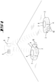
- figure 1 shows an environment, e.g. a part of a room in an apartment. Obstacles (not shown) can be arranged in the room, for example pieces of furniture, walls and the like.
- Obstacles (not shown) can be arranged in the room, for example pieces of furniture, walls and the like.
- the system has a database 5 that is commonly assigned to the tillage implements 1, 2.
- the database 5 is stored in an external storage device 8 to which both soil tillage implements 1, 2 have a data communication connection, in this case a WLAN connection, for example.
- the external storage device 8 also has a computing device 9 which can access the database 5 and select, process, overwrite or even delete data contained therein.
- the external storage device 8 is, for example, a web server (cloud) here.
- further soil cultivation devices can be integrated into the system and can also access the common database 5 within the external storage device 8.
- the memory device 8 could also be a local server arranged in the home, for example part of a base station which is designed to carry out one or more service activities for one or more soil cultivation implements 1, 2.
- the soil treatment device 1, 2 could be connected to such a base station in order, for example, to charge an accumulator or to empty a suction material collection container.
- the soil cultivation devices 1, 2 each have a local memory 7 here, which is integrated into the respective soil cultivation device 1, 2.
- a map of the environment can be stored in the local memory 7, which can be used by a navigation and self-localization system of the soil tillage implement 1, 2 to orientate itself in order to proceed automatically and without colliding with obstacles in the environment.
- a local memory 7 of one of the soil tillage implements 1, 2 could also serve as a common storage device 8 of the system and accordingly contain the database 5 commonly assigned to the soil tillage implements 1, 2.
- the database 5 is integrated locally in one of the tillage implements 1, 2, but all tillage implements 1, 2 of the system access this database 5 in order to share data and also make it available to other tillage implements 1, 2.
- the soil processing devices 1, 2 are here, for example, soil processing devices 1, 2 designed as vacuum robots. Furthermore, the soil processing devices 1, 2 can also be different devices, for example mopping devices, grinding devices, polishing devices and others. In addition, it is also possible for one or more of the soil tillage implements 1, 2 of the system not to be designed to be able to be moved automatically, but instead to be guided manually over an area to be tilled by a user.
- the tillage implements 1, 2 have here motor-driven wheels, with the help of which the respective tillage implements 1, 2 can move within the area. Furthermore, the tillage implements 1, 2 work elements 10, here for example a brush roller rotating about a substantially horizontal axis, which acts on a surface to be cleaned.
- the floor treatment devices 1, 2 have a suction mouth opening (not shown) via which air loaded with suction material can be sucked into the floor treatment device 1, 2 by means of a motor/fan unit.
- the tillage devices 1, 2 each have a rechargeable battery, not shown.
- the soil tillage implements 1, 2 are also equipped with a distance measuring device 6, which has a triangulation measuring device here, for example.
- the distance measuring device 6 measures distances to obstacles and walls within the environment.
- the distance measuring device 6 has, for example, a laser diode, the emitted light beam of which is led out of a housing of the soil tillage implement 1, 2 via a deflection device and can be rotated about an axis of rotation that is vertical in the orientation of the soil tillage implement 1, 2 shown, in particular within an angular range of 360 degrees. As a result, an all-round distance measurement around the tillage implement 1, 2 is possible.
- the environment can be measured in a preferably horizontal plane, ie in a plane parallel to the surface to be cleaned.
- the soil tillage implement 1, 2 can move while avoiding a collision with the obstacles or walls in the area.
- the environmental data recorded by the distance measuring device 6 are used to create a map of the environment.
- the soil cultivation device 1, 2 can have, for example, an odometry sensor (not shown), which measures a distance covered by the respective soil cultivation device 1, 2.
- the soil tillage implements 1, 2 also have a communication module (not shown), in particular a radio module such as a WLAN module, for example, in order to connect to the shared memory device 8.
- a communication module not shown
- a radio module such as a WLAN module
- each of the soil tillage implements 1 , 2 has a plurality of detection devices 3 , 4 .
- a detection device 3 is designed here to detect a soil type of the surface to be cleaned.
- the detection device 3 is, for example, an image acquisition device, here a camera. An image of the surface to be cleaned is recorded by means of the detection device 3 and, in order to identify a type of floor, compared with reference data which are representative of, for example, carpeted floors, wooden floors, tiles, stone floors and the like.
- the detection device 3 can also be designed to detect, in addition to the type of soil, a type of soiling and/or a degree of soiling of the surface to be cleaned.
- a further detection device 4 is, for example, an optical sensor which detects a position of a working element 10, here the brush roller, relative to the surface to be cleaned.
- Different positions of the working element 10 can be, for example, a position raised from the surface to be cleaned and a position of the working element 10 placed on the surface to be cleaned.
- the working element 10 is lifted, for example, from the surface to be cleaned.
- the working element 10 is placed, for example, on the surface to be cleaned.
- the invention now works in such a way that the soil tillage implements 1, 2 move around within the environment and carry out a cleaning activity in that they suck air into the soil tillage implement 1, 2 by means of the motor/fan unit on the one hand and, on the other hand, use the working element 10 to remove dirt from the surface to be cleaned.
- the tillage implements 1, 2 work according to preset setting parameters 12, which are settings of the individual components of the tillage implement 1, 2 in question.
- the setting parameters here are, for example, a position of the working element 10, a speed of movement of the soil tillage implement 1, 2 and a defined suction flow of the motor/fan unit of the soil tillage implement 1, 2.
- the current setting parameters 12 of the respective soil tillage implement 1, 2 are transmitted to the database 5 stored within the external memory device 8 and assigned to the respective tillage implement 1, 2 therein.
- figure 2 shows part of an exemplary database 5 in which setting parameters 12 and detection parameters 11 are stored for each tillage implement 1 , 2 .
- the setting parameters 12 and the detection parameters 11 are specified here as different values “1” and “2” in a non-dimensional manner, representing real values.
- the setting parameters 12 of the tillage devices 1, 2 represent the position of the working element 10 (brush position), the speed of movement of the tillage device 1, 2 (vehicle speed) and the nominal suction flow to be generated by the motor-fan unit (suction flow/fan) .
- the database 5 also contains - assigned to the setting parameters 12 - detection parameters 11 recorded by the detection devices 3, 4 of the tillage implements 1, 2, here for example a soil type of the area to be cleaned detected by the detection device 3 and a dirt pick-up detected by the detection device 4, which one located in the suction air flow Amount of suction material and a quantity of suction material located on the working element 10 (dirt pick-up) is concerned.
- the database 5 thus contains the detection parameters 11 recorded by the detection devices 3, 4 during operation for each of the soil tillage implements 1, 2 and its current setting parameters 12.
- the data in the database 5 are available to all soil tillage implements 1, 2 of the system.
- the computing device 9 assigned to the database 5 accesses the data stored in the database 5 and processes them further in order to calculate future setting parameters 12 for one or more soil tillage implements 1, 2.
- the detection parameters 11 and setting parameters 12 of the first soil tillage implement 1 (implement 1) in the database 5 can be accessed in order to determine setting parameters 12 for the forthcoming work operation of the second soil tillage implement depending on this 2 to derive.
- the floor treatment device 2 is to clean, for example, a carpeted floor (floor type “1”)
- the computing device 9 accesses all the data within the database 5 which relates to cleaning a carpeted floor.
- the travel speed of the soil tillage implement 1 had a value of "1" and the motor-fan unit had a nominal suction flow of "1".
- the detection parameter 11 “dirt pick-up” was detected for the first tillage implement 1 and evaluated as “high”.
- the computing device 9 determines that the setting parameters 12 of the first soil treatment device 1 on the carpeted floor type led to optimum dirt pick-up, whereupon a Control device can also control the second tillage implement 2 with these setting parameters 12 in order to achieve a "high” dirt pick-up.
- the control device can either be a control device integrated into the soil cultivation device 2 or a control device which is located in the external storage device 8 and controls the soil cultivation device 2 from the outside.
- a third tillage device (Device 3), which in the figure 1 is not shown, networked within the system.
- a detection device 4 of the device can determine, for example, that only a small amount of dirt pick-up was achieved on the carpeted floor type.
- the computing device 9 can evaluate the setting parameters 12 of the other tillage implements 1, 2 from the database 5 and filter out those setting parameters 12 which lead to a high dirt pick-up have led.
- These setting parameters 12 can then be transmitted from the computing device 9 to the control device, which then also changes the setting parameters 12 of the third device in such a way that the dirt pick-up of the third device is also “high”.
- the position of the working element 10 and the speed of movement of the device are changed, namely, for example, the position of the working element 10 is changed from a position lifted off the surface to a position placed on the surface, and the speed of the vehicle is reduced, so that the device lasts longer remains over a certain portion of the surface to be cleaned.
- the dirt pick-up can be increased overall.
- detection devices 3, 4 on the tillage implements 1, 2 can be arranged in order to detect further or other detection parameters 11.
- These detection parameters 11 can include, for example, a material, a structure and/or a degree of soiling of the surface to be cleaned, or also free or blocked mobility of the soil tillage implement 1, 2 or a working element 10 of the soil tillage implement 1, 2.
- Further detection parameters 11 can include, for example A current power consumption of an electric motor of the soil treatment device 1, 2, for example an electric motor used to drive the soil treatment device 1, 2 or a working element 10.
- Setting parameters 12 of the tillage implements 1, 2 can also be other parameters of the working element 10 or the working operation of the tillage implement 1, 2 in addition to those described above, e.g. 2, a presence and/or setting of a header of the tillage implement 1, 2 and the like. Some of the setting parameters 12 can also be detection parameters 11 at the same time.
- an intake flow of the motor-fan unit can define a nominal value as a setting parameter 12 on the one hand and an actual intake flow can be measured as a detection parameter 11 on the other hand, in the sense of a target/actual comparison. The same also applies, for example, to a speed of movement of the soil tillage implement 1, 2 or a power consumption of an electric motor of the soil tillage implement 1, 2.
Description
Die Erfindung betrifft ein System nach AnspruchThe invention relates to a system according to claim
Des Weiteren betrifft die Erfindung ein Verfahren nach Anspruch 7.Furthermore, the invention relates to a method according to
Bodenbearbeitungsgeräte sind in einer großen Vielzahl unterschiedlicher Ausführungsformen im Stand der Technik bekannt.Soil cultivation devices are known in a large number of different embodiments in the prior art.
Bei den Bodenbearbeitungsgeräten kann es sich bspw. um Saugreinigungsgeräte, Wischreinigungsgeräte, Poliergeräte, Schleifgeräte, und dergleichen handeln, welche geeignet sind, eine Fläche einer Umgebung zu bearbeiten. Die Bodenbearbeitungsgeräte können dabei entweder als von einem Nutzer handgeführte Geräte ausgebildet sein oder vorzugsweise auch als sich selbsttätig fortbewegende Bodenbearbeitungsgeräte im Sinne von mobilen autonomen Robotern.The floor treatment devices can be, for example, suction cleaning devices, wiping cleaning devices, polishing devices, grinding devices and the like, which are suitable for processing an area of an environment. The soil cultivation devices can either be in the form of devices that are hand-held by a user or preferably also as self-propelled soil cultivation devices in the sense of mobile, autonomous robots.
Es ist bekannt, die Bodenbearbeitungsgeräte zur automatisch gesteuerten Bearbeitung einer Fläche einzusetzen, wobei das Bodenbearbeitungsgerät eine Einsatztätigkeit ausführt, bspw. eine Fläche absaugt, eine Fläche mittels einer Borstenwalze reinigt, Flüssigkeit auf eine Fläche aufbringt oder dergleichen. Des Weiteren ist es auch bekannt, mehrere Bodenbearbeitungsgeräte innerhalb eines Systems zu verwenden, wobei die Bodenbearbeitungsgeräte entweder zeitgleich oder nacheinander Einsatztätigkeiten ausführen.It is known to use soil cultivation devices for automatically controlled processing of an area, with the soil cultivation device performing an activity, for example vacuuming a surface, cleaning a surface using a brush roller, applying liquid to a surface or the like. Furthermore, it is also known to use a plurality of soil cultivation devices within a system, with the soil cultivation devices carrying out operational activities either at the same time or one after the other.
Die Offenlegungsschrift
Die Offenlegungsschrift
Daneben offenbart die
Weiterer gattungsbildender Stand der Technik stellt die Druckschrift
Obwohl sich die autonomen Bodenbearbeitungsgeräte zur Bearbeitung von Flächen bewährt haben, ist es Aufgabe der Erfindung, ein System mit mehreren Bodenbearbeitungsgeräten weiterzuentwickeln.Although the autonomous tillage devices have proven themselves for tilling areas, it is the object of the invention to further develop a system with several tillage devices.
Zur Lösung der vorgenannten Aufgabe wird vorgeschlagen, dass der Detektionsparameter eine Eigenschaft einer Umgebung ist, nämlich eine Art der zu bearbeitenden Fläche als Hartboden oder Teppichboden und/oder ein Material der zu bearbeitenden Fläche und/oder eine Struktur der zu bearbeitenden Fläche, nämlich eines Hartbodens oder Teppichbodens, und/oder eine Leistungsaufnahme eines Elektromotors des Bodenbearbeitungsgerätes ist, und wobei der Einstellungsparameter des Bodenbearbeitungsgerätes ein Saugstrom einer Motor-Gebläse-Einheit und/oder eine Anwesenheit eines Vorsatzgerätes des Bodenbearbeitungsgerätes und/ oder eine Einstellung eines Saugmundes eines Vorsatzgerätes und/ oder eines Dichtelementes eines Vorsatzgerätes ist. Die Detektionsparameter sind somit Parameter einer Bodenfläche wie deren Art, nämlich ein Hartboden oder Teppichboden. Des Weiteren kann auch ein Material der Bodenfläche detektiert werden, bspw. Holz, Stein, Kunststoff, Wolle, Kork und andere. Des Weiteren kann auch die Detektion einer Struktur einer zu bearbeitenden Fläche vorteilhaft sein, bspw. ob es sich bei einem Teppichboden um einen kurzflorigen oder hochflorigen Teppich, einen Velourteppich oder dergleichen handelt und/ oder um einen Teppich mit einer bestimmten vorgegebenen oder angestrebten Florrichtung. Anhand der Detektionsparameter können Maßnahmen eines oder mehrerer Bodenbearbeitungsgeräte des Systems festgelegt werden, welche geeignet sind, die Eigenschaften der Umgebung zu berücksichtigten, beizubehalten oder zu verändern bzw. zu verbessern. Des Weiteren kann der Detektionsparameter ein Arbeitsstatus des Bodenbearbeitungsgerätes sein, nämlich eine freie oder blockierte Beweglichkeit des Bodenbearbeitungsgerätes und/ oder eine Leistungsaufnahme eines Elektromotors des Bodenbearbeitungsgerätes. Es kann somit für aktuelle Einstellungen des Bodenbearbeitungsgerätes detektiert werden, welches Verhalten das Bodenbearbeitungsgerät während des Arbeitsbetriebs zeigt. Daraus können Maßnahmen abgeleitet werden, die bspw. mit bestimmten Einstellungen des Bodenbearbeitungsgerätes einen ungewünschten Arbeitsstatus vermeiden. Bei dem ungewünschten Arbeitsstatus kann es sich bspw. um ein innerhalb der Umgebung festgefahrenes Bodenbearbeitungsgerät, ein blockiertes Bodenbearbeitungselement, wie z. B. eine rotierbare Reinigungswalze handeln. Des Weiteren kann auch die Leistungsaufnahme eines Elektromotors gemessen werden, welcher bspw. Antriebsräder des Bodenbearbeitungsgerätes oder ein Bodenbearbeitungselement antreibt. Anhand der Leistungsaufnahme des Elektromotors kann erkannt werden, ob die jeweilige angetriebene Komponente einem übermäßigen Widerstand ausgesetzt ist, bspw. aufgrund einer blockierten Bewegung. Des Weiteren wird vorgeschlagen, dass der Einstellungsparameter ein Parameter eines Arbeitselementes und/oder eines Arbeitsbetriebs des Bodenbearbeitungsgerätes ist. Insbesondere kann der Einstellungsparameter bspw. eine Stellung und/ oder eine Drehzahl und/ oder eine Geschwindigkeit eines Arbeitselementes sein, ein Saugstrom einer Motor-Gebläse-Einheit, eine Fortbewegungsgeschwindigkeit und/ oder Fortbewegungsrichtung und/oder Arbeitsrichtung des Bodenbearbeitungsgerätes, eine Anwesenheit und/oder Einstellung eines Vorsatzgerätes des Bodenbearbeitungsgerätes, nämlich eines Saugmundes und/ oder eines Dichtelementes. Der von der Recheneinrichtung berechnete Einstellungsparameter ist dabei ein Parameter, welcher zu einer vorteilhaften Einstellung der Elemente, Komponenten und/ oder Betriebsweise eines Bodenbearbeitungsgeräte in der Art führt, dass ein Arbeitsbetrieb vollständig und erfolgreich durchgeführt werden kann und dass wiederum Detektionsparameter, welche das Bodenbearbeitungsgerät während des mit diesen Einstellungsparametern durchgeführten Arbeitsbetriebs aufnimmt, einem Referenzparametern vorzugsweise ähneln oder entsprechen, d.h. eine freie Beweglichkeit des Bodenbearbeitungsgerätes ermöglichen, eine Leistungsaufnahme eines Elektromotors vorzugsweise reduzieren, eine Schmutzaufnahme des Bodenbearbeitungsgerätes möglichst erhöhen und dergleichen. Somit werden Einstellungsparameter zur Verfügung gestellt, die bspw. ein Festfahren des Bodenbearbeitungsgerätes auf einem z. B. hochflorigen Teppichboden vermeiden, eine Arbeitsrichtung in Florrichtung vorgeben, eine Bürstendrehzahl und/ oder Drehrichtung, einen Saugstrom, eine Fahrgeschwindigkeit, eine Stellung eines Saugmundes und/oder des Gehäuses des Bodenbearbeitungsgerätes so anpassen, dass keine Fehlfunktion des Bodenbearbeitungsgerätes auftritt, sondern der Arbeitsbetrieb vielmehr optimal durchgeführt werden kann. Gegebenenfalls kann auch der Austausch eines Vorsatzgerätes, bspw. eine Saugdüse, für ein Reinigungsgerät empfohlen werden oder eine Modifikation des Vorsatzgerätes, bspw. eine Applikation einer bestimmten Bürstenwalze, eine Einstellung eines Dichtelementes wie bspw. einer flexiblen Dichtleiste oder eines Borstenelementes oder dergleichen.In order to achieve the aforementioned object, it is proposed that the detection parameter is a property of an environment, namely a type of surface to be processed as a hard floor or carpet and/or a material of the surface to be processed and/or a structure of the surface to be processed, namely a hard floor or carpeting, and/or a power consumption of an electric motor of the floor treatment device, and wherein the setting parameter of the floor treatment device is a suction flow of a motor-fan unit and/or the presence of an attachment of the floor treatment device and/or a setting of a suction nozzle of a attachment and/or a Sealing element of a header is. The detection parameters are thus parameters of a floor area such as its type, namely a hard floor or carpeted floor. Furthermore, a Material of the floor surface can be detected, e.g. wood, stone, plastic, wool, cork and others. Furthermore, the detection of a structure of a surface to be processed can also be advantageous, e.g. whether the carpet is a short-pile or high-pile carpet, a velor carpet or the like and/or a carpet with a specific predetermined or desired pile direction. Based on the detection parameters, measures of one or more soil cultivation devices of the system can be defined which are suitable for taking into account, maintaining or changing or improving the properties of the environment. Furthermore, the detection parameter can be a working status of the soil cultivation device, namely a free or blocked mobility of the soil cultivation device and/or a power consumption of an electric motor of the soil cultivation device. It can thus be detected for current settings of the soil cultivation device, which behavior the soil cultivation device shows during operation. Measures can be derived from this which, for example, avoid an undesired working status with certain settings of the soil tillage implement. The undesired work status can be, for example, a soil processing device that is stuck in the area, a blocked soil processing element, such as e.g. B. act a rotatable cleaning roller. Furthermore, the power consumption of an electric motor can also be measured, which, for example, drives the drive wheels of the soil tillage implement or a soil tillage element. The power consumption of the electric motor can be used to identify whether the respective driven component is subjected to excessive resistance, for example due to a blocked movement. Furthermore, it is proposed that the setting parameter is a parameter of a working element and/or a working mode of the soil tillage implement. In particular, the setting parameter can be, for example, a position and/or a rotational speed and/or a speed of a working element, an intake flow of a motor-fan unit, a speed of movement and/or direction of movement and/or working direction of the soil tillage implement, presence and/or setting of an attachment of the soil tillage implement, namely a suction mouth and/or a sealing element. The setting parameter calculated by the computing device is a parameter which leads to an advantageous setting of the elements, components and/or mode of operation of a soil tillage implement in such a way that a work operation can be carried out completely and successfully and that in turn detection parameters which the soil tillage implement during the takes up work operation carried out with these setting parameters, preferably resemble or correspond to a reference parameter, ie enable free mobility of the soil cultivation device, preferably reduce power consumption of an electric motor, increase dirt absorption of the soil cultivation device as far as possible and the like. Thus setting parameters are made available, for example. B. avoid high-pile carpeting, specify a working direction in the direction of the pile, adjust a brush speed and/or direction of rotation, a suction current, a driving speed, a position of a suction nozzle and/or the housing of the floor treatment device in such a way that the floor treatment device does not malfunction, but rather the work operation can be carried out optimally. If necessary, the replacement of an attachment, e.g. a suction nozzle, for a cleaning device can be recommended or a modification of the attachment, e.g. application of a specific brush roller, adjustment of a sealing element such as a flexible sealing strip or a bristle element or the like.
Das System ist nun ausgebildet, eine gemeinsame Datenbank bereitzustellen, welche Detektionsparameter enthält, die von Detektionseinrichtungen mindestens zwei verschiedener Bodenbearbeitungsgeräte aufgenommen wurden. Die Detektionsparameter der unterschiedlichen Bodenbearbeitungsgeräte werden so innerhalb der gemeinsamen Datenbank vorgehalten, dass jedes Bodenbearbeitungsgerät auf Detektionsparameter anderer Bodenbearbeitungsgeräte zugreifen kann. Insbesondere kann jedes Bodenbearbeitungsgerät auf alle in der Datenbank gespeicherten Detektionsparameter zugreifen. Die Bodenbearbeitungsgeräte sind somit über die Datenbank derart innerhalb des Systems vernetzt, dass von Detektionseinrichtungen verschiedener Bodenbearbeitungsgeräte aufgenommene Detektionsparameter innerhalb der gemeinsamen Datenbank gespeichert sind und somit auch den anderen Bodenbearbeitungsgeräten für einen Arbeitsbetrieb zur Verfügung stehen. Auf der Basis der gesammelten Detektionsparameter können die Bodenbearbeitungsgeräte für ihren eigenen Arbeitsbetrieb Verbesserungen ableiten, insbesondere wenn die verwendeten bzw. zu verwendenden Einstellungsparameter der Bodenbearbeitungsgeräte identisch oder zumindest ähnlich sind. Insbesondere kann durch einen Vergleich auch verschiedener Fähigkeiten unterschiedlicher Bodenbearbeitungsgeräte und der gesammelten Detektionsparameter in Verbindung mit anstehenden Bodenbearbeitungsaufgaben eine gezielte Einsatzplanung mehrerer Bodenbearbeitungsgeräte nach deren Eignung durchgeführt werden.The system is now designed to provide a common database that contains detection parameters that were recorded by detection devices of at least two different soil cultivation implements. The detection parameters of the different tillage devices are stored within the common database in such a way that each tillage device can access the detection parameters of other tillage devices. In particular, each tillage implement can access all detection parameters stored in the database. The tillage devices are thus networked within the system via the database in such a way that detection parameters recorded by detection devices of different tillage devices are stored in the common database and are therefore also available to the other tillage devices for working operations. On the basis of the collected detection parameters, the soil cultivation devices can derive improvements for their own work operation, in particular if the setting parameters used or to be used for the soil cultivation devices are identical or at least similar. In particular, by comparing different capabilities of different soil tillage implements and the collected detection parameters in connection with pending soil tillage tasks, a targeted deployment planning of several soil tillage implements according to their suitability can be carried out.
Es wird vorgeschlagen, dass die Datenbank in einem lokalen Speicher eines Bodenbearbeitungsgerätes und/oder in einer separat zu dem Bodenbearbeitungsgerät ausgebildeten externen Speichereinrichtung gespeichert ist, insbesondere auf einem Webserver oder in einem mobilen Kommunikationsgerät. Die externe Speichereinrichtung kann insbesondere eine Cloud oder auch ein Speicher eines mobilen Kommunikationsgerätes wie bspw. eines Mobiltelefons, Tablet-Computers, Laptops oder auch eines stationären Servers, insbesondere eines Servers eines Hausautomationssystems, sein. Die gemeinsame Datenbank des Systems kann somit grundsätzlich entweder in jedem der Bodenbearbeitungsgeräte oder auch in einer separaten Einrichtung des Systems ausgebildet sein. Sofern die Datenbank in einem lokalen Speicher eines Bodenbearbeitungsgerätes gespeichert ist, greifen dennoch auch die in dem System vorhandenen anderen Bodenbearbeitungsgeräte auf diese gemeinsame Datenbank zu. Die Kommunikation zwischen den Bodenbearbeitungsgeräten und dem lokalen Speicher des Bodenbearbeitungsgerätes bzw. der externen Speichereinrichtung erfolgt vorzugsweise drahtlos, insbesondere mittels einer Funktechnologie wie WLAN, Bluetooth oder ZigBee. Darüber hinaus kann grundsätzlich auch eine drahtgebundene Kommunikation verwendet werden, bspw., wenn die Speichereinrichtung in einer Basisstation ausgebildet ist, an welcher ein Bodenbearbeitungsgerät andocken kann. Die Basisstation dient vorzugsweise nicht nur der Speicherung der Datenbank, sondern zusätzlich auch der Ausführung einer oder mehrerer Servicetätigkeiten für ein Bodenbearbeitungsgerät, bspw. dem Aufladen eines Akkumulators des Bodenbearbeitungsgerätes, dem Entleeren eines Sauggutsammelbehälters oder dergleichen. Das System kann des Weiteren bspw. einen in einem Haushalt oder im Internet befindlichen Server, einen externen Rechner bzw. eine externe Steuereinheit oder ein als solches ausgestattetes Smartphone und/ oder einen Tablet-Computer mit einer entsprechenden Applikation aufweisen und drahtlos, oder bei rein hausinternen Systemkomponenten auch drahtgebunden, mit den die Bodenbearbeitungseinrichtungen aufweisenden Bodenbearbeitungsgeräten und/oder Basisstationen verbunden sein.It is proposed that the database be stored in a local memory of a soil tillage implement and/or in an external storage device designed separately from the soil tillage implement, in particular on a web server or in a mobile communication device. The external storage device can be in particular a cloud or a memory of a mobile communication device such as a mobile phone, tablet computer, laptop or a stationary server, in particular a server of a home automation system. The common database of the system can thus in principle be configured either in each of the soil tillage implements or also in a separate device of the system. If the database is in a local memory of a tillage implement is stored, the other soil tillage implements present in the system also access this common database. The communication between the soil tillage implements and the local memory of the soil tillage implement or the external storage device preferably takes place wirelessly, in particular by means of radio technology such as WLAN, Bluetooth or ZigBee. In addition, wired communication can also be used in principle, for example if the memory device is embodied in a base station to which a soil cultivation implement can dock. The base station is preferably used not only to store the database, but also to carry out one or more service activities for a floor treatment device, for example charging a battery of the floor treatment device, emptying a suction material collection container or the like. The system can also have, for example, a server located in a household or on the Internet, an external computer or an external control unit or a smartphone equipped as such and/or a tablet computer with a corresponding application and wirelessly, or in the case of purely in-house systems System components can also be connected by wire to the soil cultivation devices and/or base stations that have the soil cultivation devices.
Das System weist des Weiteren vorzugsweise eine Recheneinrichtung auf, welche entweder eine Recheneinrichtung des Bodenbearbeitungsgerätes und/ oder eine der Datenbank zugeordnete Recheneinrichtung ist. Somit kann die Recheneinrichtung entweder in ein Bodenbearbeitungsgerät integriert sein oder wie auch die Datenbank in einer externen Einrichtung vorgesehen sein, bspw. in einer Cloud, auf einem lokalen Server eines Haushalts, in einem externen Kommunikationsgerät wie bspw. einem Mobiltelefon oder dergleichen. Die Recheneinrichtung steht in Kommunikationsverbindung mit der Datenbank.The system also preferably has a computing device, which is either a computing device of the soil tillage implement and/or a computing device assigned to the database. Thus, the computing device can either be integrated into a soil cultivation device or, like the database, can be provided in an external device, e.g. in a cloud, on a local server of a household, in an external communication device such as a mobile phone or the like. The computing device is in communication with the database.
Es wird vorgeschlagen, dass die Recheneinrichtung eingerichtet ist, von der Detektionseinrichtung aufgenommene Detektionsparameter zu verarbeiten und an die Datenbank zu übermitteln und/ oder auf in der Datenbank gespeicherte Detektionsparameter zuzugreifen und in Abhängigkeit von mindestens einem Detektionsparameter einen Einstellungsparameter eines Bodenbearbeitungsgerätes zu berechnen. Gemäß einer ersten Ausführungsform kann die Recheneinrichtung die Detektionsparameter bspw. unmittelbar von der jeweiligen Detektionseinrichtung empfangen und zumindest teilweise auswerten, wobei die sodann verarbeiteten Detektionsparameter an die Datenbank übermittelt werden und dort auch anderen Bodenbearbeitungsgeräten zur Verfügung gestellt werden. Des Weiteren können die Detektionsparameter der Detektionseinrichtung jedoch auch als Rohdaten in der Datenbank hinterlegt werden, woraufhin dann vorzugsweise eine Recheneinrichtung, welche der Datenbank zugeordnet ist, auf die in der Datenbank gespeicherten Detektionsparameter zugreift und einen Einstellungsparameter für ein Bodenbearbeitungsgerät berechnet. Die Detektionsparameter, auf welche die zentrale Recheneinrichtung zugreift, können entweder Rohdaten oder auch zumindest teil ausgewertete Detektionsparameter sein, welche dann von der zentralen Recheneinrichtung weiter verarbeitet werden, um einen Einstellungsparameter für ein Bodenbearbeitungsgerät zu generieren. Die Verarbeitung der Detektionsparameter mittels der lokalen oder auch zentralen externen Recheneinrichtung kann einen Vergleich aufgenommener Detektionsparameter eines ersten Bodenbearbeitungsgerätes mit aufgenommenen Detektionsparametern eines oder mehrerer anderer Bodenbearbeitungsgeräte beinhalten und/oder einen Vergleich mit Referenzparametern, welche bspw. einen Durchschnittswert der in einem Arbeitsbetrieb von den Bodenbearbeitungsgeräten erfolgreich verwendeten Detektionsparameter betreffen, wobei nur solche Detektionsparameter als Referenzparameter herangezogen werden, welche einen Arbeitsbetrieb erfolgreich durchführen und abschließen konnten. Der Einstellungsparameter des Bodenbearbeitungsgerätes ist somit ein solcher Einstellungsparameter, welcher gemäß einer Historie des Systems bei diesem oder auch anderen Bodenbearbeitungsgeräten zu einem Bodenbearbeitungserfolg geführt hat.It is proposed that the computing device be set up to process detection parameters recorded by the detection device and to transmit them to the database and/or to access detection parameters stored in the database and to calculate a setting parameter of a soil cultivation implement as a function of at least one detection parameter. According to a first embodiment, the computing device can, for example, receive the detection parameters directly from the respective detection device and evaluate them at least partially, with the then processed detection parameters being transmitted to the database and also being made available to other tillage implements there. Furthermore, the detection parameters of the detection device can also be stored as raw data in the database, whereupon a computing device assigned to the database accesses the detection parameters stored in the database and calculates a setting parameter for a soil tillage implement. The detection parameters, which the central computing device accesses, can either be raw data or at least partially evaluated detection parameters, which are then further processed by the central computing device in order to generate a setting parameter for a soil cultivation implement. The processing of the detection parameters by means of the local or central external computing device can include a comparison of recorded detection parameters of a first soil tillage implement with recorded detection parameters of one or more other soil tillage implements and/or a comparison with reference parameters which, for example, contain an average value of the soil tillage implements in a working operation relate to the detection parameters used, with only those detection parameters being used as reference parameters which were able to successfully carry out and complete a work operation. The setting parameter of the tillage device is thus such a setting parameter, which according to a History of the system has led to soil cultivation success with this or other soil tillage implements.
Insbesondere wird vorgeschlagen, dass der Detektionsparameter ein Detektionsparameter eines ersten Bodenbearbeitungsgerätes ist und dass der Einstellungsparameter ein Einstellungsparameter eines zweiten Bodenbearbeitungsgerätes ist. Somit ist die Recheneinrichtung eingerichtet, einen in der Datenbank gespeicherten Detektionsparameter eines ersten Bodenbearbeitungsgerätes zu verwenden, um einen Einstellungsparameter für ein anderes, zweites Bodenbearbeitungsgerät zu berechnen. In diesem Sinne erfolgt ein Austausch bzw. eine Nutzung von Detektionsparametern durch Bodenbearbeitungsgeräte, deren Detektionseinrichtung den entsprechenden Detektionsparameter nicht selbst aufgenommen haben. Dies ermöglicht eine optimale Zusammenarbeit und Unterstützung der in dem System vernetzten Bodenbearbeitungsgeräte mit Hilfe der gemeinsamen Datenbank, in welche eine Vielzahl von Detektionsparametern unterschiedlicher Bodenbearbeitungsgeräte eingepflegt werden.In particular, it is proposed that the detection parameter is a detection parameter of a first soil treatment device and that the setting parameter is a setting parameter of a second soil treatment device. Thus, the computing device is set up to use a detection parameter of a first soil treatment device stored in the database in order to calculate a setting parameter for another, second soil treatment device. In this sense, detection parameters are exchanged or used by soil tillage implements whose detection device has not recorded the corresponding detection parameter itself. This enables optimal cooperation and support for the soil tillage implements networked in the system with the help of the common database, into which a large number of detection parameters for different soil tillage implements are entered.
Des Weiteren wird vorgeschlagen, dass das System eine auf die Datenbank zugreifende Steuereinrichtung aufweist, welche eingerichtet ist, das Bodenbearbeitungsgerät unter Verwendung eines Einstellungsparameters zu steuern. Die Steuereinrichtung kann entweder eine lokale Steuereinrichtung des Bodenbearbeitungsgerätes sein oder auch eine zentrale, allen Bodenbearbeitungsgeräten gemeinsame Steuereinrichtung, welche die Funktion des Bodenbearbeitungsgerätes bzw. die Einstellung der Einstellungsparameter von extern steuert. In dem letztgenannten Fall kann die Einsatzplanung für das Bodenbearbeitungsgerät von einer zentralen Steuereinrichtung vorgenommen werden, die zentral eine gezielte Einsatzplanung eines oder mehrerer Bodenbearbeitungsgeräte nach deren Betriebseignung vorgeben kann. Die Steuereinrichtung kann eine eigene Steuereinrichtung des gesteuerten Bodenbearbeitungsgerätes oder auch eine Steuereinrichtung einer externen Einrichtung, wie bspw. eines externen PC, eines mobilen Kommunikationsgerätes, eines Webservers oder dergleichen, sein.Furthermore, it is proposed that the system has a control device which accesses the database and is set up to control the soil tillage implement using a setting parameter. The control device can either be a local control device of the soil cultivation device or also a central control device common to all soil cultivation devices, which externally controls the function of the soil cultivation device or the setting of the setting parameters. In the latter case, the operational planning for the soil cultivation device can be carried out by a central control device, which can centrally specify a targeted operational planning of one or more soil cultivation devices according to their suitability for operation. The control device can be a separate control device of the controlled soil tillage implement or also a control device of an external device, such as an external PC, a mobile communication device, a web server or the like.
Neben dem zuvor beschriebenen System wird mit der Erfindung des Weiteren auch ein Verfahren zum Betrieb eines Systems mit mindestens zwei Bodenbearbeitungsgeräten zur automatisch gesteuerten Bearbeitung einer Fläche eines Innenraumes anhand von definierten Einstellungsparametern des jeweiligen Bo-denbearbeitungsgerätes vorgeschlagen, wobei jedes der Bodenbearbeitungsgeräte mindestens ein Arbeitselement, nämlich ein von einem Elektromotor angetriebenes Bodenbearbeitungselement, und mindestens eine Detektionseinrichtung aufweist, die mindestens einen Detektionsparameter des Bodenbearbeitungsgerätes und/ oder einer Umgebung des Bodenbearbeitungsgerätes detektiert, wobei Detektionsparameter von zumindest zwei Bodenbearbeitungsgeräten den Einstellungsparametern des jeweiligen Bodenbearbeitungsgerätes zugehörig in einer den Bodenbearbeitungsgeräten gemeinsam zugeordneten Datenbank gespeichert werden, wobei der Detektionsparameter eine Eigenschaft einer Umgebung, nämlich eine Art der zu bearbeitenden Fläche als Hartboden oder Teppichboden und/ oder ein Material der zu bearbeitenden Fläche und/ oder eine Struktur der zu bearbeitenden Fläche, nämlich eines Hartbodens oder Teppichbodens, und/oder eine Leistungsaufnahme eines Elektromotors des Bodenbearbeitungsgerätes ist, und wobei der Einstellungsparameter des Bodenbearbeitungsgerätes ein Saugstrom einer Motor-Gebläse-Einheit und/oder eine Anwesenheit eines Vorsatzgerätes des Bodenbearbeitungsgerätes und/oder eine Einstellung eines Saugmundes eines Vorsatzgerätes und/oder eines Dichtelementes eines Vorsatzgerätes ist. Insbesondere kann vorgesehen sein, dass ein Einstellungsparameter eines Bodenbearbeitungsgerätes in Abhängigkeit von zumindest einem in der Datenbank gespeicherten Detektionsparameter berechnet wird.In addition to the system described above, the invention also proposes a method for operating a system with at least two tillage devices for automatically controlled processing of an area of an interior space based on defined setting parameters of the respective tillage device, with each of the tillage devices having at least one working element, namely a soil cultivation element driven by an electric motor, and has at least one detection device, which detects at least one detection parameter of the soil cultivation device and/or surroundings of the soil cultivation device, with detection parameters of at least two soil cultivation devices belonging to the setting parameters of the respective soil cultivation device being stored in a database jointly assigned to the soil cultivation devices, wherein the detection parameter is a property of an environment, namely a type of to be processed conductive surface as hard floor or carpet and/or a material of the surface to be worked and/or a structure of the surface to be worked, namely a hard floor or carpet, and/or a power consumption of an electric motor of the floor treatment device, and the setting parameter of the floor treatment device is a suction current a motor-fan unit and/or a presence of a header of the soil treatment device and/or an adjustment of a suction mouth of a header and/or a sealing element of a header. In particular, it can be provided that a setting parameter of a soil cultivation device is calculated as a function of at least one detection parameter stored in the database.
Das vorgeschlagene Verfahren eignet sich insbesondere zum Betrieb eines zuvor detailliert beschriebenen Systems aus mehreren Bodenbearbeitungsgeräten. Die zuvor in Bezug auf das System beschriebenen Merkmale und Vorteile gelten somit auch entsprechend für das Verfahren.The proposed method is particularly suitable for operating a system made up of a plurality of soil cultivation implements, which has been described in detail above. The features and advantages described above in relation to the system therefore also apply correspondingly to the method.
Das Verfahren beinhaltet, dass eine Detektionseinrichtung eines Bodenbearbeitungsgerätes als Detektionsparameter eine Eigenschaft einer Umgebung detektiert, nämlich eine Art und/ oder ein Material und/ oder eine Struktur einer zu bearbeitenden Fläche. Darüber hinaus kann als Detektionsparameter auch ein Arbeitsstatus des Bodenbearbeitungsgerätes detektiert werden, nämlich eine freie oder blockierte Beweglichkeit des Bodenbearbeitungsgerätes und/ oder eine Leistungsaufnahme eines Elektromotors des Bodenbearbeitungsgerätes. Die detektierten Detektionsparamater werden in der den Bodenbearbeitungsgeräten gemeinsam zugeordneten Datenbank gespeichert, welche Datenbank in einem lokalen Speicher eines Bodenbearbeitungsgerätes und/ oder in einer separat zu dem Bodenbearbeitungsgerät ausgebildeten externen Speichereinrichtung gespeichert ist, insbesondere auf einem Webserver oder auf einem mobilen Kommunikationsgerät. Eine Recheneinrichtung des Bodenbearbeitungsgerätes und/ oder eine der Datenbank zugeordnete Recheneinrichtung kann die Detektionsparameter auswerten und weiterverarbeiten. Insbesondere kann vorgesehen sein, dass die Recheneinrichtung von der Detektionseinrichtung aufgenommene Detektionsparameter verarbeitet und an die Datenbank übermittelt und/ oder auf in der Datenbank gespeicherte Detektionsparameter zugreift und in Abhängigkeit von mindestens einem Detektionsparameter einen Einstellungsparameter eines Bodenbearbeitungsgerätes berechnet. Vorteilhaft verarbeitet die Recheneinrichtung einen oder mehrere Detektionsparameter eines ersten Bodenbearbeitungsgerätes und berechnet daraus einen oder mehrere Einstellungsparameter eines zweiten Bodenbearbeitungsgerätes. Dadurch erfolgt eine vorzugsweise Zusammenarbeit zwischen mehreren Bodenbearbeitungsgeräten des Systems, sodass ein Bodenbearbeitungsgerät vorteilhaft in Abhängigkeit von Detektionsparametern eingestellt werden kann, die von einer Detektionseinrichtung eines oder mehrerer anderer Bodenbearbeitungsgeräte aufgenommen wurden. Somit ist es nicht notwendig, dass jedes Bodenbearbeitungsgerät des Systems alle Detektionsparameter selbst aufnimmt. Vielmehr können die Bodenbearbeitungsgeräte auch von den Informationen anderer Bodenbearbeitungsgeräte profitieren. Insbesondere können auch Arbeitsparameter, d.h. Einstellungsparameter eines Bodenbearbeitungsgerätes, durch ergänzende Simulation oder Experimentieren eines Bodenbearbeitungsvorganges ermittelt werden. Die von einer Vielzahl von Bodenbearbeitungsgeräten erfassten und in der gemeinsamen Datenbank bereitgestellten Detektionsparameter werden den einzelnen Bodenbearbeitungsgeräten zur Verfügung gestellt, wobei Einstellungsparameter der Bodenbearbeitungsgeräte in Abhängigkeit von neu aufgenommenen Detektionsparametern überschrieben werden können. Auf der Basis der großen Vielzahl von Detektionsparametern kann eine Einsatzplanung für eines oder mehrere Bodenbearbeitungsgeräte von einer zentralen Steuereinrichtung oder auch einer lokalen Steuereinrichtung eines Bodenbearbeitungsgerätes vorgenommen werden, wobei ein Abgleich der einzelnen bekannten Einstellungsparameter der Bodenbearbeitungsgeräte und der detektierten Detektionsparameter mit den anstehenden Reinigungsaufgaben eines oder mehrerer Bodenbearbeitungsgeräte erfolgt, wobei auch eine gezielte Einsatzplanung in Abhängigkeit von einer individuellen Eignung eines Bodenbearbeitungsgerätes vorgegeben werden kann. In Abhängigkeit von den verarbeiteten Detektionsparametern kann als ein Einstellungsparameter bspw. ein Parameter eines Arbeitselementes und/oder eines Arbeitsbetriebs des Bodenbearbeitungsgerätes berechnet werden. Insbesondere kann eine Stellung und/oder Drehzahl und/oder Geschwindigkeit eines Arbeitselementes vorgegeben werden, ein Saugstrom einer Motor-Gebläse-Einheit, eine Fortbewegungsgeschwindigkeit und/ oder Fortbewegungsrichtung und/ oder Arbeitsrichtung des Bodenbearbeitungsgerätes, eine Anwesenheit und/oder Einstellung eines Vorsatzgerätes des Bodenbearbeitungsgerätes, insbesondere eines Saugmundes und/oder Dichtelementes. In Abhängigkeit von den eingestellten Einstellungsparametern steuert anschließend eine lokale Steuereinrichtung des Bodenbearbeitungsgerätes oder auch eine mehreren Bodenbearbeitungsgeräten gemeinsam zugeordnete Steuereinrichtung das betreffende Bodenbearbeitungsgerät unter Verwendung eines oder mehrerer Einstellungsparameter.The method includes that a detection device of a soil cultivation device detects a property of an environment as a detection parameter, namely a type and/or a material and/or a structure of an area to be worked. In addition, a working status of the soil cultivation device can also be detected as a detection parameter, namely a free or blocked mobility of the soil cultivation device and/or a power consumption of an electric motor of the soil cultivation device. The detected detection parameters are stored in the database jointly assigned to the soil tillage implements, which database is stored in a local memory of a soil tillage implement and/or in an external storage device configured separately from the soil tillage implement, in particular on a web server or on a mobile communication device. A computing device of the soil tillage implement and/or a computing device assigned to the database can evaluate and further process the detection parameters. In particular, it can be provided that the computing device processes detection parameters recorded by the detection device and transmits them to the database and/or accesses detection parameters stored in the database and calculates a setting parameter of a soil cultivation implement as a function of at least one detection parameter. Advantageously, the computing device processes one or more detection parameters of a first soil treatment device and uses them to calculate one or more setting parameters of a second soil treatment device. As a result, there is preferably cooperation between a plurality of tillage implements in the system, so that one tillage implement can advantageously be set as a function of detection parameters that have been recorded by a detection device of one or more other tillage implements. It is therefore not necessary for each tillage implement in the system to record all detection parameters itself. Rather, the tillage implements can also benefit from the information from other tillage implements. In particular, working parameters, ie setting parameters of a soil cultivation device, can also be determined by additional simulation or experimentation of a soil cultivation process. The detection parameters recorded by a large number of soil tillage implements and made available in the common database are made available to the individual soil tillage implements provided, whereby setting parameters of the tillage implements can be overwritten depending on newly recorded detection parameters. On the basis of the large number of detection parameters, deployment planning for one or more soil tillage implements can be carried out by a central control device or a local controller of a soil tillage implement, with a comparison of the individually known setting parameters of the soil tillage implements and the detected detection parameters with the pending cleaning tasks of one or more Soil tillage equipment takes place, with a targeted application planning depending on an individual suitability of a soil tillage implement can be specified. Depending on the processed detection parameters, for example a parameter of a working element and/or a working operation of the soil cultivation device can be calculated as a setting parameter. In particular, a position and/or rotational speed and/or speed of a working element can be specified, a suction flow of a motor-fan unit, a locomotion speed and/or locomotion direction and/or working direction of the soil tillage implement, the presence and/or setting of an attachment of the soil tillage implement, in particular a suction mouth and/or sealing element. Depending on the setting parameters that have been set, a local control device of the soil cultivation device or else a control device jointly assigned to several soil cultivation devices then controls the relevant soil cultivation device using one or more setting parameters.
Im Folgenden wird die Erfindung anhand von Ausführungsbeispielen näher erläutert. Es zeigen:
- Fig. 1
- ein System mit zwei Bodenbearbeitungsgeräten und einer den Bodenbearbeitungsgeräten gemeinsam zugeordneten Datenbank;
- Fig. 2
- eine beispielhafte Datenbank für drei Bodenbearbeitungsgeräte.
- 1
- a system with two tillage implements and a database commonly assigned to the tillage implements;
- 2
- an exemplary database for three tillage implements.
Obwohl dies in der Figur nicht dargestellt ist, könnte die Speichereinrichtung 8 auch ein in der Wohnung angeordneter lokaler Server sein, bspw. ein Teil einer Basisstation, welche zur Ausführung einer oder mehrerer Servicetätigkeiten für eines oder mehrere Bodenbearbeitungsgeräte 1, 2 ausgebildet ist. Mit einer solchen Basisstation könnte sich das Bodenbearbeitungsgerät 1, 2 verbinden, um bspw. einen Akkumulator aufzuladen oder einen Sauggutsammelbehälter zu leeren.Although this is not shown in the figure, the
Die Bodenbearbeitungsgeräte 1, 2 weisen hier jeweils einen lokalen Speicher 7 auf, welcher in das jeweilige Bodenbearbeitungsgerät 1, 2 integriert ist. In dem lokalen Speicher 7 kann bspw. eine Umgebungskarte der Umgebung gespeichert werden, anhand welcher sich ein Navigations- und Selbstlokalisierungssystem des Bodenbearbeitungsgerätes 1, 2 orientieren kann, um selbsttätig und ohne Kollision mit in der Umgebung befindlichen Hindernissen zu verfahren. Des Weiteren könnte auch ein lokaler Speicher 7, eines der Bodenbearbeitungsgeräte 1, 2 als gemeinsame Speichereinrichtung 8 des Systems dienen und dementsprechend die den Bodenbearbeitungsgeräten 1, 2 gemeinsam zugeordnete Datenbank 5 enthalten. Bei dieser Ausführung ist die Datenbank 5 zwar lokal in eines der Bodenbearbeitungsgeräte 1, 2 integriert, jedoch greifen alle Bodenbearbeitungsgeräte 1, 2 des Systems auf diese Datenbank 5 zu, um Daten gemeinsam zu nutzen und auch anderen Bodenbearbeitungsgeräten 1, 2 zur Verfügung zu stellen.The
Die Bodenbearbeitungsgeräte 1, 2 sind hier bspw. als Saugroboter ausgebildete Bodenbearbeitungsgeräte 1, 2. Des Weiteren können die Bodenbearbeitungsgeräte 1, 2 auch unterschiedliche Geräte sein, bspw. Wischgeräte, Schleifgeräte, Poliergeräte und weitere. Darüber hinaus ist es auch möglich, dass eines oder mehrere der Bodenbearbeitungsgeräte 1, 2 des Systems nicht selbsttätig verfahrbar ausgebildet sind, sondern von einem Nutzer manuell über eine zu bearbeitende Fläche geführt werden. Die Bodenbearbeitungsgeräte 1, 2 verfügen hier über motorisch angetriebene Räder, mit deren Hilfe sich das jeweilige Bodenbearbeitungsgeräte 1, 2 innerhalb der Umgebung fortbewegen kann. Des Weiteren weisen die Bodenbearbeitungsgeräte 1, 2 Arbeitselemente 10 auf, hier bspw. eine um eine im Wesentlichen horizontale Achse rotierende Borstenwalze, die auf eine zu reinigende Fläche einwirkt. Weiter weisen die Bodenbearbeitungsgeräte 1, 2 eine nicht weiter dargestellte Saugmundöffnung auf, über welche mittels einer Motor-Gebläse-Einheit mit Sauggut beaufschlagte Luft in das Bodenbearbeitungsgerät 1, 2 eingesaugt werden kann. Für die Elektroversorgung der Elektrokomponenten der Bodenbearbeitungsgeräte 1, 2, wie für den Antrieb der Räder, der Arbeitselemente 10 und des Weiteren vorgesehene Elektronik, weisen die Bodenbearbeitungsgeräte 1, 2 jeweils einen nicht dargestellten, wiederaufladbaren Akkumulator auf.The
Die Bodenbearbeitungsgeräte 1, 2 sind des Weiteren mit einer Abstandsmesseinrichtung 6 ausgestattet, welche hier bspw. eine Triangulationsmesseinrichtung aufweist. Die Abstandsmesseinrichtung 6 misst Abstände zu Hindernissen und Wänden innerhalb der Umgebung. Die Abstandsmesseinrichtung 6 weist im Einzelnen bspw. eine Laserdiode auf, deren emittierter Lichtstrahl über eine Umlenkeinrichtung aus einem Gehäuse des Bodenbearbeitungsgerätes 1, 2 herausgeführt und um eine in der gezeigten Orientierung des Bodenbearbeitungsgerätes 1, 2 senkrecht stehende Drehachse rotierbar ist, insbesondere innerhalb eines Winkelbereiches von 360 Grad. Dadurch ist eine Rundum-Abstandsmessung um das Bodenbearbeitungsgerät 1, 2 möglich. Mit Hilfe der Abstandsmesseinrichtung 6 kann die Umgebung in einer bevorzugt horizontalen Ebene vermessen werden, d.h. in einer zu der zu reinigenden Fläche parallelen Ebene. Dadurch kann das Bodenbearbeitungsgerät 1, 2 unter Vermeidung einer Kollision mit den Hindernissen bzw. Wänden in der Umgebung verfahren. Die mittels der Abstandsmesseinrichtung 6 aufgenommenen Umgebungsdaten werden zur Erstellung einer Umgebungskarte der Umgebung genutzt. Des Weiteren kann das Bodenbearbeitungsgerät 1, 2 bspw. einen nicht dargestellten Odometrie-Sensor aufweisen, welcher eine von dem jeweiligen Bodenbearbeitungsgerät 1, 2 zurückgelegte Wegstrecke misst. Des Weiteren ist es auch möglich, dass ein Bodenbearbeitungsgerät 1, 2 bspw. einen Kontaktsensor oder dergleichen aufweist.The soil tillage implements 1, 2 are also equipped with a
Die Bodenbearbeitungsgeräte 1, 2 weisen des Weiteren ein Kommunikationsmodul (nicht dargestellt) auf, insbesondere ein Funkmodul wie bspw. ein WLAN-Modul, um sich mit der gemeinsamen Speichereinrichtung 8 zu verbinden.The soil tillage implements 1, 2 also have a communication module (not shown), in particular a radio module such as a WLAN module, for example, in order to connect to the shared
Des Weiteren weist jedes der Bodenbearbeitungsgeräte 1, 2 mehrere Detektionseinrichtungen 3, 4 auf. Eine Detektionseinrichtung 3 ist hier zur Erfassung einer Bodenart der zu reinigenden Fläche ausgebildet. Die Detektionseinrichtung 3 ist bspw. eine Bilderfassungseinrichtung, hier eine Kamera. Mittels der Detektionseinrichtung 3 wird ein Bild der zu reinigenden Fläche aufgenommen und zur Erkennung einer Bodenart mit Referenzdaten verglichen, welche stellvertretend für bspw. Teppichboden, Holzboden, Fliesen, Steinboden und dergleichen sind. Des Weiteren kann die Detektionseinrichtung 3 zusätzlich auch ausgebildet sein, neben der Bodenart eine Verschmutzungsart und/oder einen Verschmutzungsgrad der zu reinigenden Fläche zu detektieren. Eine weitere Detektionseinrichtung 4 ist bspw. ein optischer Sensor, welcher eine Stellung eines Arbeitselementes 10, hier der Borstenwalze, relativ zu der zu reinigenden Fläche erkennt. Unterschiedliche Stellungen des Arbeitselementes 10 können bspw. eine von der zu reinigenden Fläche abgehobene Stellung und eine auf die zu reinigende Fläche aufgesetzte Stellung des Arbeitselementes 10 sein. Bei der Reinigung eines hochflorigen Teppichbodens ist das Arbeitselement 10 bspw. von der zu reinigenden Fläche abgehoben. Im Falle eines kurzflorigen Teppichbodens ist Arbeitselement 10 hingegen bspw. auf die zu reinigende Fläche aufgesetzt.Furthermore, each of the soil tillage implements 1 , 2 has a plurality of
Die Erfindung funktioniert nun so, dass die Bodenbearbeitungsgeräte 1, 2 innerhalb der Umgebung umherfahren und dabei eine Reinigungstätigkeit ausführen, indem diese einerseits mittels der Motor-Gebläse-Einheit Luft in das Bodenbearbeitungsgerät 1, 2 einsaugen und andererseits mittels des Arbeitselementes 10 Schmutz von der zu reinigenden Fläche aufnehmen. Dabei arbeiten die Bodenbearbeitungsgeräte 1, 2 nach voreingestellten Einstellungsparametern 12, welche Einstellungen der einzelnen Komponenten des jeweiligen Bodenbearbeitungsgerätes 1, 2 sind. Hier handelt es sich bei den Einstellungsparametern bspw. um eine Stellung des Arbeitselementes 10, eine Fortbewegungsgeschwindigkeit des Bodenbearbeitungsgerätes 1, 2 und einen definierten Saugstrom der Motor-Gebläse-Einheit des Bodenbearbeitungsgerätes 1, 2. Die aktuellen Einstellungsparameter 12 des jeweiligen Bodenbearbeitungsgerätes 1, 2 werden an die innerhalb der externen Speicheinrichtung 8 gespeicherte Datenbank 5 übermittelt und darin dem jeweiligen Bodenbearbeitungsgerät 1, 2 zugeordnet.The invention now works in such a way that the soil tillage implements 1, 2 move around within the environment and carry out a cleaning activity in that they suck air into the soil tillage implement 1, 2 by means of the motor/fan unit on the one hand and, on the other hand, use the working
Für den Betrieb des zweiten Bodenbearbeitungsgerätes 2 (Gerät 2) kann bspw. auf die in der Datenbank 5 befindlichen Detektionsparameter 11 und Einstellungsparameter 12 des ersten Bodenbearbeitungsgerätes 1 (Gerät 1) zugegriffen werden, um in Abhängigkeit davon Einstellungsparameter 12 für den anstehenden Arbeitsbetrieb des zweiten Bodenbearbeitungsgerätes 2 abzuleiten. Falls das Bodenbearbeitungsgerät 2 hier bspw. auf einem Teppichboden (Bodenart "1") reinigen soll, greift die Recheneinrichtung 9 auf all diejenigen Daten innerhalb der Datenbank 5 zu, welche Reinigungen eines Teppichbodens betreffen. Hier kann der Datenbank 5 bspw. aus dem Datensatz des ersten Bodenbearbeitungsgerätes 1 entnommen werden, dass die Bodenart Teppichboden mit einer Bürstenstellung "1", welche einer auf die zu reinigende Fläche aufgesetzten Stellung entspricht, bearbeitet wurde. Des Weiteren hatte die Fortbewegungsgeschwindigkeit des Bodenbearbeitungsgerätes 1 einen Betrag von "1" und die Motor-Gebläse-Einheit hatte einen Nenn-Saugstrom von "1". Bei diesen Einstellungsparametern 12 wurde für das erste Bodenbearbeitungsgerät 1 der Detektionsparameter 11 "Schmutzaufnahme" detektiert und als "hoch" bewertet. Die Recheneinrichtung 9 stellt daraufhin fest, dass die Einstellungsparameter 12 des ersten Bodenbearbeitungsgerätes 1 auf der Bodenart Teppichboden zu einer optimalen Schmutzaufnahme führten, woraufhin eine Steuereinrichtung auch das zweite Bodenbearbeitungsgerät 2 mit diesen Einstellungsparametern 12 steuern kann, um eine "hohe" Schmutzaufnahme zu erreichen. Die Steuereinrichtung kann entweder eine in das Bodenbearbeitungsgerät 2 integrierte Steuereinrichtung sein oder eine in der externen Speichereinrichtung 8 befindliche Steuereinrichtung, welche das Bodenbearbeitungsgerät 2 von außen steuert.For the operation of the second soil tillage implement 2 (implement 2), for example, the
Des Weiteren kann bspw. ein drittes Bodenbearbeitungsgerät (Gerät 3), welches in der
Obwohl dies in dem Ausführungsbeispiel nicht beschrieben wurde, können auch andere Detektionseinrichtungen 3, 4 an den Bodenbearbeitungsgeräten 1, 2 angeordnet sein, um weitere oder andere Detektionsparameter 11 zu detektieren. Zu diesen Detektionsparametern 11 können bspw. ein Material, eine Struktur und/oder ein Verschmutzungsgrad der zu reinigenden Fläche zählen, oder auch eine freie oder blockierte Beweglichkeit des Bodenbearbeitungsgerätes 1, 2 oder eines Arbeitselementes 10 des Bodenbearbeitungsgerätes 1, 2. Weitere Detektionsparameter 11 können bspw. eine aktuelle Leistungsaufnahme eines Elektromotors des Bodenbearbeitungsgerätes 1, 2 sein, bspw. ein für einen Antrieb des Bodenbearbeitungsgerätes 1, 2 oder eines Arbeitselementes 10 verwendeter Elektromotor.Although this has not been described in the exemplary embodiment,
Einstellungsparameter 12 der Bodenbearbeitungsgeräte 1, 2 können neben den zuvor Beschriebenen auch weitere Parameter des Arbeitselementes 10 oder des Arbeitsbetriebs des Bodenbearbeitungsgerätes 1, 2 sein, bspw. eine Drehzahl und/oder Geschwindigkeit eines Arbeitselementes 10, eine Fortbewegungsrichtung und/oder Arbeitsrichtung des Bodenbearbeitungsgerätes 1, 2, eine Anwesenheit und/oder Einstellung eines Vorsatzgerätes des Bodenbearbeitungsgerätes 1, 2 und dergleichen. Einige der Einstellungsparameter 12 können gleichzeitig auch Detektionsparameter 11 sein. Bspw. kann ein Saugstrom der Motor-Gebläse-Einheit einerseits einen Nennwert als Einstellungsparameter 12 definieren und andererseits ein tatsächlicher Saugstrom als Detektionsparameter 11 gemessen werden, im Sinne eines Soll-Ist-Vergleiches. Gleiches gilt ebenfalls bspw. für eine Fortbewegungsgeschwindigkeit des Bodenbearbeitungsgerätes 1, 2 oder eine Leistungsaufnahme eines Elektromotors des Bodenbearbeitungsgerätes 1, 2.Setting
- 11
- Bodenbearbeitungsgerättillage implement
- 22
- Bodenbearbeitungsgerättillage implement
- 33
- Detektionseinrichtungdetection device
- 44
- Detektionseinrichtungdetection device
- 55
- DatenbankDatabase
- 66
- Abstandsmesseinrichtungdistance measuring device
- 77
- SpeicherStorage
- 88th
- Speichereinrichtungstorage facility
- 99
- Recheneinrichtungcomputing device
- 1010
- Arbeitselementwork item
- 1111
- Detektionsparameterdetection parameters
- 1212
- Einstellungsparametersetting parameters
Claims (8)
- System comprising at least two floor treatment apparatuses (1, 2) for treating a surface of an interior space in an automatically controlled manner on the basis of defined adjustment parameters (12) of the relevant floor treatment apparatus (1, 2), each of the floor treatment apparatuses (1, 2) having at least one working element (10), specifically a floor treatment element driven by an electric motor, and at least one detection device (3, 4) for detecting at least one detection parameter (11) of the floor treatment apparatus (1, 2) and/or a surroundings of the floor treatment apparatus (1, 2), the system having a database (5) which is jointly assigned to the floor treatment apparatuses (1, 2) and in which detection parameters (11) of at least two floor treatment apparatuses (1, 2) are stored in association with the adjustment parameters (12) of the relevant floor treatment apparatus (1, 2), characterised in that the detection parameter (11) is a property of a surroundings, specifically a type of the surface to be treated as hard floor or carpet, and/or a material of the surface to be treated and/or a structure of the surface to be treated, specifically a hard floor or carpet, and/or a power consumption of an electric motor of the floor treatment apparatus (1, 2), and the adjustment parameter of the floor treatment apparatus (1, 2) being a suction flow of a motor-blower unit and/or a presence of an attachment of the floor treatment apparatus (1, 2) and/or an adjustment of a suction mouth of an attachment and/or of a sealing element of an attachment.
- System according to claim 1, characterised in that the database (5) is stored in a local memory (7) of a floor treatment apparatus (1, 2) and/or in an external storage device (8) formed separately from the floor treatment apparatus (1, 2).
- System according to either of the preceding claims, characterised by a computing device (9) of the floor treatment apparatus (1, 2) and/or a computing device (9) assigned to the database (5).
- System according to claim 3, characterised in that the computing device (9) is designed to process detection parameters (11) recorded by the detection device (3, 4) and to transmit them to the database (5) and/or to access detection parameters (11) stored in the database (5) and to calculate an adjustment parameter (12) of a floor treatment apparatus (1, 2) as a function of at least one detection parameter (11).
- System according to claim 4, characterised in that the detection parameter (11) is a detection parameter (11) of a first floor treatment apparatus (1, 2) and in that the adjustment parameter (12) is an adjustment parameter (12) of a second floor treatment apparatus (2, 1).
- System according to any of the preceding claims, characterised by a control device which accesses the database (5) and is designed to control the floor treatment apparatus (1, 2) using an adjustment parameter (12).
- Method for operating a system comprising at least two floor treatment apparatuses (1, 2) for treating a surface of an interior space in an automatically controlled manner on the basis of defined adjustment parameters (12) of the relevant floor treatment apparatus (1, 2), each of the floor treatment apparatuses (1, 2) having at least one working element (10), specifically a floor treatment element driven by an electric motor, and at least one detection device (3, 4) which detects at least one detection parameter (11) of the floor treatment apparatus (1, 2) and/or a surroundings of the floor treatment apparatus (1, 2), detection parameters (11) of at least two floor treatment apparatuses (1, 2) being stored in a database (5) which is jointly assigned to the floor treatment apparatuses (1, 2), in association with the adjustment parameters (12) of the relevant floor treatment apparatus (1, 2), characterised in that the detection parameter (11) is a property of a surroundings, specifically a type of the surface to be treated as hard floor or carpet, and/or a material of the surface to be treated and/or a structure of the surface to be treated, specifically a hard floor or carpet, and/or a power consumption of an electric motor of the floor treatment apparatus (1, 2), and the adjustment parameter of the floor treatment apparatus (1, 2) being a suction flow of a motor-blower unit and/or a presence of an attachment of the floor treatment apparatus (1, 2) and/or an adjustment of a suction mouth of an attachment and/or of a sealing element of an attachment.
- Method according to claim 7, characterised in that an adjustment parameter (12) of a floor treatment apparatus (1, 2) is calculated as a function of at least one detection parameter (11) stored in the database (5).
Applications Claiming Priority (1)
| Application Number | Priority Date | Filing Date | Title |
|---|---|---|---|
| DE102017113287.2A DE102017113287A1 (en) | 2017-06-16 | 2017-06-16 | System with at least two soil tillage implements |
Publications (2)
| Publication Number | Publication Date |
|---|---|
| EP3416018A1 EP3416018A1 (en) | 2018-12-19 |
| EP3416018B1 true EP3416018B1 (en) | 2022-01-19 |
Family
ID=62684598
Family Applications (1)
| Application Number | Title | Priority Date | Filing Date |
|---|---|---|---|
| EP18176975.3A Active EP3416018B1 (en) | 2017-06-16 | 2018-06-11 | System comprising at least two ground processing devices |
Country Status (7)
| Country | Link |
|---|---|
| US (1) | US10694912B2 (en) |
| EP (1) | EP3416018B1 (en) |
| JP (1) | JP2019000630A (en) |
| CN (1) | CN109144048B (en) |
| DE (1) | DE102017113287A1 (en) |
| ES (1) | ES2908287T3 (en) |
| TW (1) | TW201907253A (en) |
Families Citing this family (9)
| Publication number | Priority date | Publication date | Assignee | Title |
|---|---|---|---|---|
| DE102017118381A1 (en) * | 2017-08-11 | 2019-02-14 | Vorwerk & Co. Interholding Gmbh | Method for operating a self-propelled soil tillage implement |
| DE102017118383A1 (en) | 2017-08-11 | 2019-02-14 | Vorwerk & Co. Interholding Gmbh | Method for operating a self-propelled cleaning device |
| DE102017118382A1 (en) * | 2017-08-11 | 2019-02-14 | Vorwerk & Co. Interholding Gmbh | Method for operating a self-propelled cleaning device |
| DE102019105936A1 (en) * | 2019-03-08 | 2020-09-10 | Vorwerk & Co. Interholding Gesellschaft mit beschränkter Haftung | Suction material collecting station, system consisting of a suction material collecting station and a suction cleaning device as well as processes for it |
| DE102019106227A1 (en) * | 2019-03-12 | 2020-09-17 | Vorwerk & Co. Interholding Gmbh | Soil cultivation device and system consisting of a soil cultivation device and an external device |
| DE102019109596A1 (en) * | 2019-04-11 | 2020-10-15 | Vorwerk & Co. Interholding Gmbh | System consisting of a manually operated soil cultivation device, an exclusively automatically operated soil cultivation device and a computing device |
| DE102020100447A1 (en) * | 2020-01-10 | 2021-07-15 | Vorwerk & Co. Interholding Gmbh | Method for operating a system with two automatically moving soil cultivation devices and a system for carrying out such a method |
| EP4098162B1 (en) * | 2021-06-01 | 2023-10-18 | Vorwerk & Co. Interholding GmbH | Floor working implement and method for setting a parameter range on a floor working implement and system comprising a floor working implement and an external terminal |
| CN114451830B (en) * | 2022-03-17 | 2023-06-16 | 上海飞博激光科技股份有限公司 | Device for cleaning glass curtain wall by laser and cleaning method thereof |
Citations (1)
| Publication number | Priority date | Publication date | Assignee | Title |
|---|---|---|---|---|
| US20160157422A1 (en) * | 2013-07-15 | 2016-06-09 | Koubachi AG | System for monitoring and controlling activities of at least one gardening tool within at least one activity zone |
Family Cites Families (9)
| Publication number | Priority date | Publication date | Assignee | Title |
|---|---|---|---|---|
| DE102004010827B4 (en) * | 2004-02-27 | 2006-01-05 | Alfred Kärcher Gmbh & Co. Kg | Soil cultivation device and method for its control |
| DE102007010979B3 (en) * | 2007-03-05 | 2008-05-08 | Miele & Cie. Kg | Floor space cleaning method, involves controlling processing intensity of individual area of floor space in flowing processing cycle based on degree of pollution of individual area of floor space |
| US8755936B2 (en) * | 2008-01-28 | 2014-06-17 | Seegrid Corporation | Distributed multi-robot system |
| US8386078B1 (en) * | 2011-05-06 | 2013-02-26 | Google Inc. | Methods and systems for providing a data library for robotic devices |
| EP2851760A1 (en) * | 2013-09-19 | 2015-03-25 | Rigas Tehniska universitate | Multi-robot system |
| JP6390965B2 (en) * | 2014-04-11 | 2018-09-19 | パナソニックIpマネジメント株式会社 | Self-propelled cleaner, control device, and automatic cleaning system |
| DE102014105460A1 (en) * | 2014-04-16 | 2015-10-22 | Vorwerk & Co. Interholding Gmbh | Self-propelled floor cleaning device with a follower tool following a leader vehicle |
| DE102015104250A1 (en) * | 2015-03-20 | 2016-09-22 | Miele & Cie. Kg | Floor care appliance and method of maintaining an at least partially carpeted floor with a self-propelled floor care appliance |
| DE102015006014A1 (en) * | 2015-05-13 | 2016-11-17 | Universität Bielefeld | Soil cultivation device and method for its navigation and swarm of tillage equipment and methods for their joint navigation |
-
2017
- 2017-06-16 DE DE102017113287.2A patent/DE102017113287A1/en not_active Withdrawn
-
2018
- 2018-06-04 JP JP2018106772A patent/JP2019000630A/en active Pending
- 2018-06-11 ES ES18176975T patent/ES2908287T3/en active Active
- 2018-06-11 EP EP18176975.3A patent/EP3416018B1/en active Active
- 2018-06-13 CN CN201810605896.4A patent/CN109144048B/en active Active
- 2018-06-14 TW TW107120553A patent/TW201907253A/en unknown
- 2018-06-14 US US16/008,178 patent/US10694912B2/en active Active
Patent Citations (1)
| Publication number | Priority date | Publication date | Assignee | Title |
|---|---|---|---|---|
| US20160157422A1 (en) * | 2013-07-15 | 2016-06-09 | Koubachi AG | System for monitoring and controlling activities of at least one gardening tool within at least one activity zone |
Also Published As
| Publication number | Publication date |
|---|---|
| CN109144048A (en) | 2019-01-04 |
| US10694912B2 (en) | 2020-06-30 |
| TW201907253A (en) | 2019-02-16 |
| CN109144048B (en) | 2023-05-19 |
| US20180360283A1 (en) | 2018-12-20 |
| ES2908287T3 (en) | 2022-04-28 |
| DE102017113287A1 (en) | 2018-12-20 |
| JP2019000630A (en) | 2019-01-10 |
| EP3416018A1 (en) | 2018-12-19 |
Similar Documents
| Publication | Publication Date | Title |
|---|---|---|
| EP3416018B1 (en) | System comprising at least two ground processing devices | |
| EP3415070B1 (en) | System comprising at least two ground processing devices | |
| EP2741483B1 (en) | Mobile cleaning device and method for one's operation | |
| EP3412191B1 (en) | Automatic soil preparation equipment | |
| EP3441840B1 (en) | Method for operating a self-propelled cleaning device | |
| DE102010000174B4 (en) | Method for cleaning a room using an automatically movable cleaning device | |
| EP3416019B1 (en) | System comprising at least two automatic advancing ground working tools | |
| EP3454715B1 (en) | System and method for cleaning a floor by means of a cleaning robot | |
| EP3685722B1 (en) | System consisting of a purely manually guided soil processing device and an automatically operated soil processing device and method for operating such a system | |
| EP2982285A2 (en) | Floor cleaning device for dry and wet cleaning and method for operating a self-propelled floor cleaning device | |
| EP3415065A1 (en) | System comprising two cleaning devices | |
| DE102009041362A1 (en) | Method for operating a cleaning robot | |
| EP3243418B1 (en) | System and method for cleaning a floor with a robotic cleaner | |
| EP3441842A1 (en) | Method for operating an automatically moving soil-working implement | |
| EP3538967A1 (en) | Method for operating an automatically moving robot | |
| DE102015100419A1 (en) | Method and arrangement for processing floor surfaces | |
| EP3613321B1 (en) | Floor processing apparatus which moves independently within an environment | |
| DE102012112035A1 (en) | Robot vacuum cleaner operating method, involves transferring processing date to vacuum cleaner in operation of robot vacuum cleaner as result of processing control information returns to cleaner for activation of cleaner by individual | |
| EP3559773B1 (en) | Method for the navigation and self-location of an autonomously moving processing device | |
| EP3967198A1 (en) | Automatic soil preparation equipment | |
| EP3683645B1 (en) | System comprising a first ground processing device and a second ground processing device and method for operating such a system | |
| DE102015104244A1 (en) | Floor care appliance and method of maintaining a floor with a self-propelled floor care appliance | |
| EP3825802B1 (en) | System with at least two automatic cleaning robots and method of operating the said system | |
| EP3848770B1 (en) | Method for operating a system with at least two automatically moving soil working devices and system for carrying out such a method | |
| DE102015104251B4 (en) | Floor maintenance device and method of maintenance of a hard floor with a self-propelled floor maintenance device |
Legal Events
| Date | Code | Title | Description |
|---|---|---|---|
| PUAI | Public reference made under article 153(3) epc to a published international application that has entered the european phase |
Free format text: ORIGINAL CODE: 0009012 |
|
| STAA | Information on the status of an ep patent application or granted ep patent |
Free format text: STATUS: THE APPLICATION HAS BEEN PUBLISHED |
|
| AK | Designated contracting states |
Kind code of ref document: A1 Designated state(s): AL AT BE BG CH CY CZ DE DK EE ES FI FR GB GR HR HU IE IS IT LI LT LU LV MC MK MT NL NO PL PT RO RS SE SI SK SM TR |
|
| AX | Request for extension of the european patent |
Extension state: BA ME |
|
| STAA | Information on the status of an ep patent application or granted ep patent |
Free format text: STATUS: REQUEST FOR EXAMINATION WAS MADE |
|
| 17P | Request for examination filed |
Effective date: 20190425 |
|
| RBV | Designated contracting states (corrected) |
Designated state(s): AL AT BE BG CH CY CZ DE DK EE ES FI FR GB GR HR HU IE IS IT LI LT LU LV MC MK MT NL NO PL PT RO RS SE SI SK SM TR |
|
| STAA | Information on the status of an ep patent application or granted ep patent |
Free format text: STATUS: EXAMINATION IS IN PROGRESS |
|
| 17Q | First examination report despatched |
Effective date: 20190725 |
|
| STAA | Information on the status of an ep patent application or granted ep patent |
Free format text: STATUS: EXAMINATION IS IN PROGRESS |
|
| GRAP | Despatch of communication of intention to grant a patent |
Free format text: ORIGINAL CODE: EPIDOSNIGR1 |
|
| STAA | Information on the status of an ep patent application or granted ep patent |
Free format text: STATUS: GRANT OF PATENT IS INTENDED |
|
| INTG | Intention to grant announced |
Effective date: 20210823 |
|
| GRAS | Grant fee paid |
Free format text: ORIGINAL CODE: EPIDOSNIGR3 |
|
| STAA | Information on the status of an ep patent application or granted ep patent |
Free format text: STATUS: GRANT OF PATENT IS INTENDED |
|
| GRAA | (expected) grant |
Free format text: ORIGINAL CODE: 0009210 |
|
| STAA | Information on the status of an ep patent application or granted ep patent |
Free format text: STATUS: THE PATENT HAS BEEN GRANTED |
|
| AK | Designated contracting states |
Kind code of ref document: B1 Designated state(s): AL AT BE BG CH CY CZ DE DK EE ES FI FR GB GR HR HU IE IS IT LI LT LU LV MC MK MT NL NO PL PT RO RS SE SI SK SM TR |
|
| REG | Reference to a national code |
Ref country code: GB Ref legal event code: FG4D Free format text: NOT ENGLISH |
|
| REG | Reference to a national code |
Ref country code: CH Ref legal event code: EP |
|
| REG | Reference to a national code |
Ref country code: DE Ref legal event code: R096 Ref document number: 502018008556 Country of ref document: DE |
|
| REG | Reference to a national code |
Ref country code: AT Ref legal event code: REF Ref document number: 1464159 Country of ref document: AT Kind code of ref document: T Effective date: 20220215 |
|
| REG | Reference to a national code |
Ref country code: IE Ref legal event code: FG4D Free format text: LANGUAGE OF EP DOCUMENT: GERMAN |
|
| REG | Reference to a national code |
Ref country code: ES Ref legal event code: FG2A Ref document number: 2908287 Country of ref document: ES Kind code of ref document: T3 Effective date: 20220428 |
|
| REG | Reference to a national code |
Ref country code: LT Ref legal event code: MG9D |
|
| REG | Reference to a national code |
Ref country code: NL Ref legal event code: MP Effective date: 20220119 |
|
| PG25 | Lapsed in a contracting state [announced via postgrant information from national office to epo] |
Ref country code: NL Free format text: LAPSE BECAUSE OF FAILURE TO SUBMIT A TRANSLATION OF THE DESCRIPTION OR TO PAY THE FEE WITHIN THE PRESCRIBED TIME-LIMIT Effective date: 20220119 |
|
| PG25 | Lapsed in a contracting state [announced via postgrant information from national office to epo] |
Ref country code: SE Free format text: LAPSE BECAUSE OF FAILURE TO SUBMIT A TRANSLATION OF THE DESCRIPTION OR TO PAY THE FEE WITHIN THE PRESCRIBED TIME-LIMIT Effective date: 20220119 Ref country code: RS Free format text: LAPSE BECAUSE OF FAILURE TO SUBMIT A TRANSLATION OF THE DESCRIPTION OR TO PAY THE FEE WITHIN THE PRESCRIBED TIME-LIMIT Effective date: 20220119 Ref country code: PT Free format text: LAPSE BECAUSE OF FAILURE TO SUBMIT A TRANSLATION OF THE DESCRIPTION OR TO PAY THE FEE WITHIN THE PRESCRIBED TIME-LIMIT Effective date: 20220519 Ref country code: NO Free format text: LAPSE BECAUSE OF FAILURE TO SUBMIT A TRANSLATION OF THE DESCRIPTION OR TO PAY THE FEE WITHIN THE PRESCRIBED TIME-LIMIT Effective date: 20220419 Ref country code: LT Free format text: LAPSE BECAUSE OF FAILURE TO SUBMIT A TRANSLATION OF THE DESCRIPTION OR TO PAY THE FEE WITHIN THE PRESCRIBED TIME-LIMIT Effective date: 20220119 Ref country code: HR Free format text: LAPSE BECAUSE OF FAILURE TO SUBMIT A TRANSLATION OF THE DESCRIPTION OR TO PAY THE FEE WITHIN THE PRESCRIBED TIME-LIMIT Effective date: 20220119 Ref country code: BG Free format text: LAPSE BECAUSE OF FAILURE TO SUBMIT A TRANSLATION OF THE DESCRIPTION OR TO PAY THE FEE WITHIN THE PRESCRIBED TIME-LIMIT Effective date: 20220419 |
|
| PG25 | Lapsed in a contracting state [announced via postgrant information from national office to epo] |
Ref country code: PL Free format text: LAPSE BECAUSE OF FAILURE TO SUBMIT A TRANSLATION OF THE DESCRIPTION OR TO PAY THE FEE WITHIN THE PRESCRIBED TIME-LIMIT Effective date: 20220119 Ref country code: LV Free format text: LAPSE BECAUSE OF FAILURE TO SUBMIT A TRANSLATION OF THE DESCRIPTION OR TO PAY THE FEE WITHIN THE PRESCRIBED TIME-LIMIT Effective date: 20220119 Ref country code: GR Free format text: LAPSE BECAUSE OF FAILURE TO SUBMIT A TRANSLATION OF THE DESCRIPTION OR TO PAY THE FEE WITHIN THE PRESCRIBED TIME-LIMIT Effective date: 20220420 Ref country code: FI Free format text: LAPSE BECAUSE OF FAILURE TO SUBMIT A TRANSLATION OF THE DESCRIPTION OR TO PAY THE FEE WITHIN THE PRESCRIBED TIME-LIMIT Effective date: 20220119 |
|
| PG25 | Lapsed in a contracting state [announced via postgrant information from national office to epo] |
Ref country code: IS Free format text: LAPSE BECAUSE OF FAILURE TO SUBMIT A TRANSLATION OF THE DESCRIPTION OR TO PAY THE FEE WITHIN THE PRESCRIBED TIME-LIMIT Effective date: 20220519 |
|
| REG | Reference to a national code |
Ref country code: DE Ref legal event code: R097 Ref document number: 502018008556 Country of ref document: DE |
|
| PG25 | Lapsed in a contracting state [announced via postgrant information from national office to epo] |
Ref country code: SM Free format text: LAPSE BECAUSE OF FAILURE TO SUBMIT A TRANSLATION OF THE DESCRIPTION OR TO PAY THE FEE WITHIN THE PRESCRIBED TIME-LIMIT Effective date: 20220119 Ref country code: SK Free format text: LAPSE BECAUSE OF FAILURE TO SUBMIT A TRANSLATION OF THE DESCRIPTION OR TO PAY THE FEE WITHIN THE PRESCRIBED TIME-LIMIT Effective date: 20220119 Ref country code: RO Free format text: LAPSE BECAUSE OF FAILURE TO SUBMIT A TRANSLATION OF THE DESCRIPTION OR TO PAY THE FEE WITHIN THE PRESCRIBED TIME-LIMIT Effective date: 20220119 Ref country code: EE Free format text: LAPSE BECAUSE OF FAILURE TO SUBMIT A TRANSLATION OF THE DESCRIPTION OR TO PAY THE FEE WITHIN THE PRESCRIBED TIME-LIMIT Effective date: 20220119 Ref country code: DK Free format text: LAPSE BECAUSE OF FAILURE TO SUBMIT A TRANSLATION OF THE DESCRIPTION OR TO PAY THE FEE WITHIN THE PRESCRIBED TIME-LIMIT Effective date: 20220119 Ref country code: CZ Free format text: LAPSE BECAUSE OF FAILURE TO SUBMIT A TRANSLATION OF THE DESCRIPTION OR TO PAY THE FEE WITHIN THE PRESCRIBED TIME-LIMIT Effective date: 20220119 |
|
| PLBE | No opposition filed within time limit |
Free format text: ORIGINAL CODE: 0009261 |
|
| STAA | Information on the status of an ep patent application or granted ep patent |
Free format text: STATUS: NO OPPOSITION FILED WITHIN TIME LIMIT |
|
| PG25 | Lapsed in a contracting state [announced via postgrant information from national office to epo] |
Ref country code: AL Free format text: LAPSE BECAUSE OF FAILURE TO SUBMIT A TRANSLATION OF THE DESCRIPTION OR TO PAY THE FEE WITHIN THE PRESCRIBED TIME-LIMIT Effective date: 20220119 |
|
| 26N | No opposition filed |
Effective date: 20221020 |
|
| PG25 | Lapsed in a contracting state [announced via postgrant information from national office to epo] |
Ref country code: MC Free format text: LAPSE BECAUSE OF FAILURE TO SUBMIT A TRANSLATION OF THE DESCRIPTION OR TO PAY THE FEE WITHIN THE PRESCRIBED TIME-LIMIT Effective date: 20220119 |
|
| REG | Reference to a national code |
Ref country code: CH Ref legal event code: PL |
|
| REG | Reference to a national code |
Ref country code: BE Ref legal event code: MM Effective date: 20220630 |
|
| PG25 | Lapsed in a contracting state [announced via postgrant information from national office to epo] |
Ref country code: SI Free format text: LAPSE BECAUSE OF FAILURE TO SUBMIT A TRANSLATION OF THE DESCRIPTION OR TO PAY THE FEE WITHIN THE PRESCRIBED TIME-LIMIT Effective date: 20220119 |
|
| GBPC | Gb: european patent ceased through non-payment of renewal fee |
Effective date: 20220611 |
|
| PG25 | Lapsed in a contracting state [announced via postgrant information from national office to epo] |
Ref country code: LU Free format text: LAPSE BECAUSE OF NON-PAYMENT OF DUE FEES Effective date: 20220611 Ref country code: LI Free format text: LAPSE BECAUSE OF NON-PAYMENT OF DUE FEES Effective date: 20220630 Ref country code: IE Free format text: LAPSE BECAUSE OF NON-PAYMENT OF DUE FEES Effective date: 20220611 Ref country code: CH Free format text: LAPSE BECAUSE OF NON-PAYMENT OF DUE FEES Effective date: 20220630 |
|
| PG25 | Lapsed in a contracting state [announced via postgrant information from national office to epo] |
Ref country code: GB Free format text: LAPSE BECAUSE OF NON-PAYMENT OF DUE FEES Effective date: 20220611 Ref country code: BE Free format text: LAPSE BECAUSE OF NON-PAYMENT OF DUE FEES Effective date: 20220630 |
|
| P01 | Opt-out of the competence of the unified patent court (upc) registered |
Effective date: 20230517 |
|
| PGFP | Annual fee paid to national office [announced via postgrant information from national office to epo] |
Ref country code: FR Payment date: 20230622 Year of fee payment: 6 Ref country code: DE Payment date: 20230620 Year of fee payment: 6 |
|
| PGFP | Annual fee paid to national office [announced via postgrant information from national office to epo] |
Ref country code: IT Payment date: 20230630 Year of fee payment: 6 Ref country code: ES Payment date: 20230719 Year of fee payment: 6 |
|
| REG | Reference to a national code |
Ref country code: DE Ref legal event code: R079 Ref document number: 502018008556 Country of ref document: DE Free format text: PREVIOUS MAIN CLASS: G05D0001020000 Ipc: G05D0001430000 |
|
| PG25 | Lapsed in a contracting state [announced via postgrant information from national office to epo] |
Ref country code: HU Free format text: LAPSE BECAUSE OF FAILURE TO SUBMIT A TRANSLATION OF THE DESCRIPTION OR TO PAY THE FEE WITHIN THE PRESCRIBED TIME-LIMIT; INVALID AB INITIO Effective date: 20180611 |
|
| PG25 | Lapsed in a contracting state [announced via postgrant information from national office to epo] |
Ref country code: MK Free format text: LAPSE BECAUSE OF FAILURE TO SUBMIT A TRANSLATION OF THE DESCRIPTION OR TO PAY THE FEE WITHIN THE PRESCRIBED TIME-LIMIT Effective date: 20220119 Ref country code: CY Free format text: LAPSE BECAUSE OF FAILURE TO SUBMIT A TRANSLATION OF THE DESCRIPTION OR TO PAY THE FEE WITHIN THE PRESCRIBED TIME-LIMIT Effective date: 20220119 |