EP3224997B1 - Communication path switching apparatus, method for controlling communication path switching apparatus, and computer program product - Google Patents
Communication path switching apparatus, method for controlling communication path switching apparatus, and computer program product Download PDFInfo
- Publication number
- EP3224997B1 EP3224997B1 EP15862681.2A EP15862681A EP3224997B1 EP 3224997 B1 EP3224997 B1 EP 3224997B1 EP 15862681 A EP15862681 A EP 15862681A EP 3224997 B1 EP3224997 B1 EP 3224997B1
- Authority
- EP
- European Patent Office
- Prior art keywords
- data
- unit
- communication
- communication path
- path switching
- Prior art date
- Legal status (The legal status is an assumption and is not a legal conclusion. Google has not performed a legal analysis and makes no representation as to the accuracy of the status listed.)
- Active
Links
Images


Classifications
-
- H—ELECTRICITY
- H04—ELECTRIC COMMUNICATION TECHNIQUE
- H04L—TRANSMISSION OF DIGITAL INFORMATION, e.g. TELEGRAPHIC COMMUNICATION
- H04L12/00—Data switching networks
- H04L12/28—Data switching networks characterised by path configuration, e.g. LAN [Local Area Networks] or WAN [Wide Area Networks]
- H04L12/46—Interconnection of networks
- H04L12/4633—Interconnection of networks using encapsulation techniques, e.g. tunneling
-
- H—ELECTRICITY
- H04—ELECTRIC COMMUNICATION TECHNIQUE
- H04L—TRANSMISSION OF DIGITAL INFORMATION, e.g. TELEGRAPHIC COMMUNICATION
- H04L41/00—Arrangements for maintenance, administration or management of data switching networks, e.g. of packet switching networks
- H04L41/08—Configuration management of networks or network elements
- H04L41/0803—Configuration setting
- H04L41/0813—Configuration setting characterised by the conditions triggering a change of settings
- H04L41/0816—Configuration setting characterised by the conditions triggering a change of settings the condition being an adaptation, e.g. in response to network events
-
- H—ELECTRICITY
- H04—ELECTRIC COMMUNICATION TECHNIQUE
- H04L—TRANSMISSION OF DIGITAL INFORMATION, e.g. TELEGRAPHIC COMMUNICATION
- H04L41/00—Arrangements for maintenance, administration or management of data switching networks, e.g. of packet switching networks
- H04L41/08—Configuration management of networks or network elements
- H04L41/0895—Configuration of virtualised networks or elements, e.g. virtualised network function or OpenFlow elements
-
- H—ELECTRICITY
- H04—ELECTRIC COMMUNICATION TECHNIQUE
- H04L—TRANSMISSION OF DIGITAL INFORMATION, e.g. TELEGRAPHIC COMMUNICATION
- H04L45/00—Routing or path finding of packets in data switching networks
- H04L45/302—Route determination based on requested QoS
- H04L45/306—Route determination based on the nature of the carried application
-
- H—ELECTRICITY
- H04—ELECTRIC COMMUNICATION TECHNIQUE
- H04L—TRANSMISSION OF DIGITAL INFORMATION, e.g. TELEGRAPHIC COMMUNICATION
- H04L45/00—Routing or path finding of packets in data switching networks
- H04L45/38—Flow based routing
-
- H—ELECTRICITY
- H04—ELECTRIC COMMUNICATION TECHNIQUE
- H04W—WIRELESS COMMUNICATION NETWORKS
- H04W12/00—Security arrangements; Authentication; Protecting privacy or anonymity
- H04W12/06—Authentication
-
- H—ELECTRICITY
- H04—ELECTRIC COMMUNICATION TECHNIQUE
- H04W—WIRELESS COMMUNICATION NETWORKS
- H04W40/00—Communication routing or communication path finding
- H04W40/02—Communication route or path selection, e.g. power-based or shortest path routing
Definitions
- the present invention relates to a communication path switching apparatus, a method for controlling a communication path switching apparatus, and a computer program product.
- IP Internet Protocol
- IP packets are substantially converging to Ethernet (registered trademark) for wire communication, and are substantially converging to a third generation (3G)/Long Term Evolution (LTE) system for long-distance wireless communication and to The Institute of Electrical and Electronics Engineers, Inc (IEEE) 802.11 wireless local area network (LAN) system, which is known as a nickname of Wireless Fidelity (Wi-Fi) for middle-distance and short-distance wireless communication.
- 3G Third Generation
- LTE Long Term Evolution
- IEEE Institute of Electrical and Electronics Engineers, Inc
- Wi-Fi Wireless Fidelity
- SDN software defined network
- the concept called a software defined network (SDN) has been gaining attention in recent years.
- the SDN literally means that operation of a network is defined with software description, and includes, as major technical components receiving the most attention, virtualization of a network, and Open Flow Switching that is one of the methods and protocols for controlling the virtual communication and is open specifications independent of a vendor.
- Open Flow (registered trademark) is a technique for defining communication as an end-to-end flow and performing path control, load distribution, optimization, and the like for each flow, and standardization of which has been promoted by a nonprofit organization called Open Networking Foundation (ONF).
- relay apparatuses such as a switching hub (switch) of a data communication path do not analyze and forward each data packet in an autonomous distributed manner, but an apparatus called a controller centrally controls the relay apparatuses.
- Open Flow separates a control plane serving as a part for analyzing data, determining a forwarding destination, and controlling determination controlling from a data plane simply serving as a part for physically forwarding a packet.
- An Open Flow controller (OFC) responsible for the former instructs a forwarding rule
- an Open Flow switch (OFS) responsible for the latter performs forwarding based on an instruction of the OFC, specifically, on a flow table of the OFS to which the OFC makes an addition and performs rewrite.
- This mechanism is used to utilize Open Flow as a tool for controlling the network virtualization.
- SDN related techniques such as network virtualization and Open Flow are increasingly utilized in Web/cloud data centers on which communication loads concentrate among IP communication networks, a communication carrier backbone and the like, and flexible optimization control achieves efficiency of communication traffic, reduction in the number of network apparatuses and the like, and reduction in cost and energy and the like.
- Open Flow Such a technique called Open Flow has been already known.
- Patent Literature 1 discloses a communication method and the like where high-order protocol information is included in a Transmission Control Protocol (TCP) header for the purpose of improving conformability of a computer system and providing a computer system capable of performing flow control corresponding to a higher-order protocol than that of a TCP
- Patent Literature 2 discloses a configuration that can perform access control for each user/client, without arranging an Authenticator or an EAPoL pass switch at each location.
- a forwarding node processes a packet between a supplicant and a prescribed authentication device, in accordance with a processing rule that has been set.
- the authentication device performs a prescribed authentication procedure with the supplicant and notifies a result thereof to a control server.
- Patent Literature 3 discloses the design and advantages of a novel programmable NIC, PNIC, oriented data center network architecture, a prototype of a PNIC based virtual switch that supports virtual NICs, OpenFlow switching, clock synchronization and flow monitoring.
- Patent Literature 4 discloses a computer comprising a virtual network interface device; a first virtual switch connected to a first physical network interface device; a second virtual switch connected to a second physical network interface device; a communication analysis unit (or path control unit) that, based on a result of communication with a packet transmission destination obtained by analysing a packet transmitted from the virtual network interface device, selects to which of the first virtual switch and the second virtual switch the virtual network interface device is to be connected; and a connection setting unit that holds a connection between the virtual switch selected by the communication analysis unit (or path control unit) and the virtual network interface device.
- a communication analysis unit or path control unit
- an Open Flow switch When an Open Flow switch (OFS) is connected to a network interface such as a network interface card (NIC) in the same machine, the OFS may intercept all data received by the NIC. As a result, other service or software having normally received and processed data before the OFS is connected to a network interface such as the NIC cannot receive data, and a service or software having conventionally acquired and used specific data from the NIC cannot be normally processed.
- OFS Open Flow switch
- NIC network interface card
- the present invention provides a communication path switching apparatus capable of normally executing, even when the OFS is connected to a network interface, a service or software that is normally executed without connecting the OFS to a network interface.
- a communication path switching apparatus according to independent claim 1
- a method for controlling a communication path switching apparatus according to independent claim 5 and a computer program product comprising a non-transitory computer-usable medium having a computer program that causes a computer in a communication path switching apparatus according to independent claim 6.
- Preferred embodiments of the invention are defined by the dependent claims.
- the present invention can provide a communication path switching apparatus capable of normally executing, even when the OFS is connected to a network interface, a service or software that is normally executed without connecting the OFS to a network interface.
- Open Flow Switching is a technique for defining communication as an end-to-end flow and separating a control plane serving as a part for analyzing data, determining a forwarding destination determining, and controlling determination from a data plane serving as a part for physically forwarding a packet.
- an Open Flow controller OFC
- An Open Flow switch OFS responsible for processing of the data plane forwards a packet based on an instruction from the OFC. Specifically, the OFC adds and rewrites a flow entry of the OFS, and the OFS forwards a packet based on the flow entry.
- FIG. 1 is a diagram illustrating a model in which communication functions implemented on a communication path switching apparatus are divided into a hierarchical structure.
- This model is the Open System Interconnection (OSI) reference model, and has seven layers from the physical layer that is the first layer to the application layer that is the seventh layer.
- OSI Open System Interconnection
- IP Internet Protocol
- Examples of a service include the Web, extensible markup language (XML) Web service, mail, messaging, file sharing, and file forwarding illustrated in the fifth layer to the seventh layer in FIG. 1 .
- XML extensible markup language
- applications providing the service use the Transmission Control Protocol/Internet Protocol (TCP/IP) and the User Datagram Protocol/IP (UDP/IP) illustrated in the third and the fourth layers, the applications are not necessarily conscious of communication layers of the first and the second layers lower than the third and the fourth layers.
- TCP/IP Transmission Control Protocol/Internet Protocol
- UDP/IP User Datagram Protocol/IP
- a communication apparatus can have a general hardware and software configuration for developing the IP packet based communication applications illustrated in FIG. 1 .
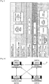
- FIGS. 2A and 2B are diagrams illustrating the configuration of a conventional path switching switch and the configuration of Open Flow Switching, respectively.
- each relay apparatus performs path control in an autonomous distributed manner and determines a forwarding destination of a packet.
- each switch 20 as a relay apparatus has both path control and packet forwarding functions, and executes both processing.
- each switch 20 In Open Flow Switching, as illustrated in FIG. 2B , the path control function of each switch 20 is separated and is implemented on an Open Flow controller (OFC) 21, and only the function of forwarding a packet is implemented on each Open Flow switch (OFS) 22 as the switch 20.
- the OFC 21 controls all information on path control, and this OFC 21 performs central control of the behavior of each OFS 22 so as to enable flexible control.
- TCP Transmission Control Protocol
- HTTP Hyper Text Transfer Protocol
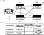
- FIG. 3 is a diagram illustrating the configuration of a flow table stored in the OFS.
- the OFS 22 performs processing such as forwarding of a frame based on the information in the flow table illustrated in FIG. 3 .
- the flow table includes flow entries representing a frame control rule as illustrated in FIG. 3 .
- the flow table includes components for identifying the flow entries and the corresponding three kinds of information that are conditions, statistical information, and processing.
- the components include fields for inputting "flow entry 1", "flow entry 2", and the like in order to identify each entry.
- the conditions are header fields and include fields for inputting information illustrated in FIG. 8 , which will be described later, in order to identify and specify communication.
- the statistical information includes fields for managing how much communication satisfying the conditions occurs and how far processing has proceeded.
- the processing includes fields for defining processing for a frame. Examples of the processing include forwarding a frame (Forward), enqueueing a frame in a specified queue (Enqueue), dropping a frame (Drop), and modifying a value of a specified field (Modify-Field). Examples also include executing predetermined processing for a specific group (Group), and adding a tag and removing a tag (Push-Tag and Pop-Tag). In addition, processing can be specified in more detail, and in the "Forward" processing, forwarding a frame to all physical ports, encapsulating and sending a frame to a controller, and the like can be specified.
- the OFS when the OFS is used by being connected to a network interface card (NIC) serving as an example of a network interface receiving data from the outside of an apparatus, the OFS forwards a packet to a virtual NIC based on a flow entry setting from the OFC.
- NIC network interface card
- the present invention has characteristics in that the virtual NIC forwards data to a service or software utilizing specific data through a socket and the like. The characteristics of the present invention will be specifically described with the following drawings.
- FIG. 4 is a diagram illustrating an example of a hardware block that illustrates the schematic configuration of a communication path switching apparatus in accordance with the embodiment.
- the communication path switching apparatus in the embodiment includes a central processing unit (CPU) 451, a read only memory (ROM) 452, and a random access memory (RAM) 453.
- the communication path switching apparatus in the embodiment also includes a hard disk drive (HDD) 454, a display 455, an input apparatus 456, and communication interfaces 458 and 459.
- CPU central processing unit
- ROM read only memory
- RAM random access memory
- HDD hard disk drive
- the CPU 451, the ROM 452, the RAM 453, the HDD 454, the display 455, the input apparatus 456, and the communication interfaces 458 and 459 are connected to each other via a bus 460.
- the CPU 451 controls operation of the whole communication path switching apparatus.
- the CPU 451 loads a software program for controlling operation of the communication path switching apparatus from the ROM 452, and executes the software program using the RAM 453 as a working memory.
- the ROM 452 is a non-volatile memory, and stores therein a boot program and various kinds of computer programs, and data.
- the RAM 453 is a volatile memory, and temporarily stores therein data input through the communication interfaces, which will be described later.
- the HDD 454 is a large-capacity non-volatile storage apparatus. The HDD stores therein data to be forwarded and the like.
- the input apparatus 456 is an operating unit of the communication path switching apparatus and is a user interface. Examples of the input apparatus 456 include buttons and a touch panel, and an input apparatus with a light emitting diode (LED), a sensor, and the like.
- the display 455 includes a liquid crystal display (LCD) and the like, and can be a user interface when the input apparatus 456 has the touch panel configuration.
- the communication interfaces 458 and 459 connect a device driver, a layer 2 (L2), an nl80211_driver, and the like as described later.
- the device driver and the L2 are something like packets of Ethernet.
- the nl80211_driver is a driver of a wireless LAN that is an extension of an application program interface (API) for a wireless LAN.
- API application program interface
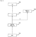
- FIG. 5 is a diagram illustrating an example of a function block that illustrates a schematic configuration of the communication path switching apparatus in accordance with the embodiment.
- the communication path switching apparatus in the embodiment includes an application unit 551, a data switching unit 552, a virtual device unit 553, a controller 554, a determining unit 555, and a confirming unit 556.
- the application unit 551, the data switching unit 552, the virtual device unit 553, the controller 554, the determining unit 555, and the confirming unit 556 are connected to each other via a bus 557.
- the CPU 451 executes a computer program written into the ROM 452 so as to implement the application unit 551, the data switching unit 552, the virtual device unit 553, the controller 554, and the determining unit 555.
- the application unit 551 is application software that executes a certain function, and examples of the application unit 551 include the nl80211_driver that is a driver (software) necessary for performing wireless LAN communication such as Wi-Fi.
- the data switching unit 552 has a function of forwarding data for causing the application unit 551 to execute the certain function, and examples of the data switching unit 552 include the OFS where a flow entry serving as order information such as forwarding of a packet is set.
- the virtual device unit 553 has a function of forwarding data forwarded from the data switching unit 552 to the application unit 551. Examples of the virtual device unit 553 include the virtual NIC that forwards an Extensible Authentication Protocol over LAN (EAPoL) packet received by the NIC to the application unit 551.
- EAPoL Extensible Authentication Protocol over LAN
- EAPoL is a protocol used for authenticating wireless communication with another communication apparatus.
- An EAPoL packet is a protocol that is an extension of Extensible Authentication Protocol (EAP), and the EAPoL packet is a packet used for the EAPoL (protocol).
- EAP Extensible Authentication Protocol
- the controller 554 has a function of making a setting so that the data switching unit 552 forwards data for causing the application unit 551 to execute a certain function.
- Examples of the controller 554 include the OFC that sets a flow entry serving as order information such as forwarding of a packet to the OFS.
- the determining unit 555 has a function of determining whether data received by the data switching unit 552 is certain data, for example, determining whether the received data is an EAPoL packet.
- the confirming unit 556 has a function of confirming whether the controller 554 has made a setting for forwarding the data received by the data switching unit 552 when the data is not certain data. For example, when data received by the OFS is not an EAPoL packet, the confirming unit 556 confirms whether a flow entry for forwarding the packet is set in the OFS.
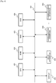
- FIG. 6 is a diagram illustrating a specific example that illustrates an outline of a network configuration in a LAN.
- user terminals such as a PC1 41 and a PC2 42 are connected to a layer 2 (L2) switch 46 by wire.
- user terminals such as a tablet computer 44, a smartphone 45, and a PC3 43 are connected to a wireless LAN access point (AP) 48 wirelessly.
- the L2 switch 46 and the wireless LAN AP 48 are connected to a layer 3 (L3) switch 47 by wire.
- the L2 switch 46 represents Ethernet as an example of wire communication in the data link layer that is the second layer in the OSI reference model.
- the L3 switch 47 represents packet communication based on the IP in the network layer that is the third layer in the OSI reference model.
- FIG. 7 is a diagram illustrating processing when an information processing apparatus, for example, a PC performs communication using the TCP, the IP, and the like.
- layers (L) in each block such as IP (L3) 503 and IP (L3) 506, and Ethernet (L2) 504 and Ethernet (L2) 505 correspond to respective layers forming the OSI reference model.
- the right-side block executes transmission processing of data in an application
- the left-side block executes reception processing of the data through media such as a cable and a wireless channel.
- the transmission processing is performed in the order from an application layer (L5 and higher) 501 serving as an upper layer to the Ethernet (L2) 504 serving as a lower layer.
- the reception processing is performed in the order from the Ethernet (L2) 505 serving as a lower layer to an application layer (L5 and higher) 508 serving as an upper layer.
- Processing of the upper layers such as the application (L5 and higher) 501 and the application (L5 and higher) 508, TCP (L4) 502 and TCP (L4) 507, and the IP (L3) 503 and the IP (L3) 506 is generally executed by software processing using a CPU, a memory, and the like. Processing of lower layers is often executed by dedicated hardware. However, processing of layers may be different depending on the difference in uses, for example, a PC and a server.
- FIG. 8 is a diagram illustrating a frame format in DIX Ethernet. There are a plurality of formats for the Ethernet frame format, but only a typical one is selected and described below.
- a preamble 61 is positioned in the beginning of a frame format. This is a signal for causing an interface connected to a LAN to recognize a start of a frame and for giving a timing to synchronize.
- the preamble 61 is a field the size of which is 8 octets (64 bits), and 1 and 0 are alternately continued and the last bit (the 64th bit) is 1 in the field.
- a transmission destination address 62 is a field the size of which is 6 octets (48 bits), and sets a media access control (MAC) address of an interface of a station that is a transmission destination.
- the transmission destination address 62 can set a multicast address addressed to a plurality of interfaces.
- a transmission source address 63 is a field the size of which is 6 octets (48 bits), and sets a MAC address of an interface transmitting a frame.
- a type field 64 is a field the size of which is 2 octets (16 bits).
- the type field 64 sets an identifier that indicates an upper layer protocol stored in the following data field for multiplexing/demultiplexing. For example, if an upper layer protocol is the EAPoL, the type field 64 contains the number 0 ⁇ 888E, and a data field 65 contains an EAP protocol packet. If an upper layer protocol is the Internet Protocol version (IPv) 4, the type field 64 contains the number 0 ⁇ 0800, and the data field 65 contains an IPv4 protocol packet.
- IPv Internet Protocol version
- the data field 65 can store therein variable length information from the minimum 46 octets to the maximum 1,500 octets.
- a frame check sequence (FCS) 66 is a 4-octet field for detecting an error of a frame.
- the FCS 66 sets a cyclic redundancy check (CRC) value calculated from each field of the transmission destination address 62, the transmission source address 63, the type field 64, and the data field 65. Similarly, a CRC value is calculated on a reception side. When the CRC value on a reception side does not match the CRC value of the FCS 66 on a transmission side, it is determines to be an error, and the corresponding frame is dropped.
- CRC cyclic redundancy check
- FIG. 9 is a diagram illustrating how a packet flows through each layer in the OSI reference model when a general NIC receives data.
- the description will be made with a specific example where a wireless LAN card serving as an example of the NIC receives data.
- An NIC is an abbreviation for a network interface card, but hereinafter, the NIC includes not only a conventional hardware interface but also a software interface.
- processing of creating a packet is applied to data received by an NIC 701. Subsequently, processing is executed in a layer 3 (L3) 703 and a layer 4 (L4) 704.
- L3 layer 3
- L4 layer 4
- the device driver and the L2 702 execute processing of the L2, and is, for example, something like an Ethernet packet.
- an EAPoL packet in the L2 702 is forwarded to an nl80211_driver 705 using a socket.
- the hostapd means open source software implementation for an access point of a wireless LAN and the like.
- the nl80211_driver 705 is a wireless LAN driver that is an extension of an API for a wireless LAN.
- a value of the type field 64 in the frame format illustrated in FIG. 8 may be used for distributing processing from the device driver and the L2 702 to the L3 703 and processing from the device driver and the L2 702 to the nl80211_driver 705.
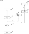
- FIG. 10 is a diagram illustrating how a packet flows when the OFS and the OFC are added to FIG. 9 .
- an OFS 801 and an OFC 802 are added to the configuration in FIG. 9 .
- using the OFS 801 causes data such as a packet, a frame, and the like in communication not to flow into the L3 703 or the nl80211_driver 705 indicated by dotted-line paths. All of the data flows into the OFS 801 indicated by a solid-line path 1.
- the nl80211_driver 705 serving as a driver (software) necessary for implementing a function of a wireless LAN such as Wi-Fi is connected to the OFS 801. Accordingly, all of the information necessary for operating the driver flows into the OFS 801 and fails to be transferred to the nl80211_driver 705.
- the nl80211_driver 705 is in a standby state in order to receive information necessary for operating itself at any time.
- the OFS 801 is controlled by the OFC 802 through a path @.
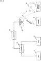
- FIG. 11 is a diagram illustrating how an EAPoL packet flows into specific software and the like through a virtual NIC in the configuration illustrated in FIG. 10 .
- the EAPoL presented as a specific example is a protocol that is an extension of the EAP, and an EAPoL packet is a packet used for the EAPoL (protocol).
- the following describes the configuration where an EAPoL packet flows into the nl80211_driver 705 through the OFS 801 and a virtual NIC 901 step by step.
- the OFC 802 sets a flow entry indicating that all of the data input into the OFS 801 is forwarded to the virtual NIC 901 in a flow table of the OFS 801 through the path @.
- the OFC 802 also changes the setting so that an interface (for example, a socket interface) receiving an EAPoL packet of the nl80211_driver 705 receives data transmitted from the virtual NIC 901.
- the OFS 801 forwards all of the input EAPoL packets to the virtual NIC 901 through a path 2.
- the nl80211_driver 705 receives the EAPoL packets transmitted from the virtual NIC 901 through a path 3. This flow enables an EAPoL packet received by the NIC 701 to be forwarded to application software executing a specific function such as the nl80211_driver 705, and the like.
- FIGS. 12 and 13 are flowcharts illustrating the operation of the communication path switching apparatus in the embodiment.
- the communication path switching apparatus is initialized at Step S111. All processing blocks forming the communication path switching apparatus are made to be operable at Step S112.
- the OFC 802 presets a flow entry (order information such as forwarding of a packet) to the OFS 801 at Step S113, if necessary.
- Step S122 When the communication path switching apparatus is initialized at Step S121 in FIG. 13 , it is determined whether a packet is received at Step S122. If a packet is determined to be received (YES), the process goes to processing at Step S123. If not (NO), the communication path switching apparatus waits until a packet is received.
- processing is performed from a lower layer in layers. Processing from the NIC 701 to the L2 702 illustrated in FIG. 11 is executed at Step S123.
- the OFS 801 receives data at Step S124. It is determined whether the received data is an EAPoL packet at Step S125. If the data is determined to be an EAPoL packet (YES), the process goes to processing at Step S126. If not (NO), the process goes to processing at Step S129.
- the OFS 801 forwards the EAPoL packet to the virtual NIC 901 at Step S126.
- the virtual NIC 901 forwards the EAPoL packet to the nl80211_driver 705 at Step S127.
- the nl80211_driver 705 processes the EAPoL packet at Step S128, and all processing ends. In other words, if data is an EAPoL packet, the packet is forwarded to the OFS 801, the virtual NIC 901, and the nl80211_driver 705 in this order based on the flow entry of the OFS 801.
- the packet is forwarded based on the set flow entry at Step S130, and processing ends.
- the OFS 801 inquires of the OFC 802 for a method of processing a packet, and processing ends at Step S131. Depending on a method of implementing the OFS 801, processing after an inquiry to the OFC 802 and processing for a case where no flow entry is preset to the OFS 801 is performed.
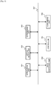
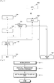
- FIG. 14 is a diagram illustrating the configuration where the NIC is inserted between the OFC and the OFS in the configuration illustrated in FIG. 11 .
- an NIC 101 is inserted between the OFS 801 and the OFC 802 illustrated in FIG. 11 .
- a communication path switching apparatus 100 can be controlled by the OFC 802 provided outside the communication path switching apparatus 100, and the OFC 802 can be provided as an apparatus different from the OFS 801.
- a specific example can be considered in which something like a wireless LAN AP is assumed as a communication path switching apparatus, and this wireless LAN AP is controlled by the OFC 802 provided outside the wireless LAN AP. It is also assumed that a plurality of communication path switching apparatuses 100 are provided, and these communication path switching apparatuses 100-1, 100-2, ⁇ , and 100-n may be controlled by an order from the single OFC 802 provided outside.
- the OFS when the OFS is connected to the NIC, the OFS directly takes all of the data from the device driver and the L2.
- the OFS operates in this manner because it prevents data from flowing into processing of an IP packet such as performed in the L3 and the L4 when the OFS is installed and operated in the operation of the kernel of Linux (registered trademark).
- an upper layer (nl80211_driver) of a wireless LAN When processing of an upper layer (nl80211_driver) of a wireless LAN is performed, the OFS often receives data from the device_driver and the L2.
- the OFS takes all of the data as described above, and the nl80211_driver cannot receive data copied from the data, from the OFS.
- the OFC sets, to the OFS, a rule for forwarding the data taken by the OFS, and changes the setting of the nl80211_driver so that the data is transferred from the virtual NIC to the nl80211_driver.
- data is transmitted to the OFS, and the data passes through the virtual NIC and is forwarded to the nl80211_driver again. Accordingly, only changing the setting of the nl80211_driver is required without changing the implementation of the inside of the OFS.
- the OFS is connected to the virtual NIC while the OFS is connected to the NIC, and the OFC sets a flow entry to the OFS so that the OFS forwards specific data out of the data received from the NIC to the virtual NIC.
- the OFC also changes the setting of the nl80211_driver so that data is forwarded from the virtual NIC to the nl80211_driver.
- the data is forwarded to the NIC, the OFS, and the virtual NIC in this order, and the virtual NIC forwards the data to a service or software that uses the data. In this manner, even when the OFS and the NIC are connected to each other, processing can be normally executed in a service or software that conventionally acquires specific data from the NIC, and uses and processes the data.
- a computer program on a computer can execute the operation flows of the communication path switching apparatus according to the embodiment illustrated in FIGS. 12 and 13 .
- the CPU 451 integrated in the controller 554 that forms a communication path switching apparatus loads a computer program stored in a storage unit such as the ROM 452.
- Each processing step in the computer program is sequentially executed so as to execute the operation flows.
- the present invention enables a service or software that is normally executed without connecting an OFS to a network interface to be executed even when the OFS is connected to the network interface. Accordingly, the present invention can provide a useful communication path switching apparatus, method for controlling the communication path switching apparatus, and computer program product that cannot be obtained by the conventional technique.
Landscapes
- Engineering & Computer Science (AREA)
- Computer Networks & Wireless Communication (AREA)
- Signal Processing (AREA)
- Computer Security & Cryptography (AREA)
- Data Exchanges In Wide-Area Networks (AREA)
- Mobile Radio Communication Systems (AREA)
Description
- The present invention relates to a communication path switching apparatus, a method for controlling a communication path switching apparatus, and a computer program product.
- In a communication network from wide area communication such as public lines and medium-scale area communication such as a company premise local area network (LAN) down to short-distance communication connecting user terminals in an office room, a meeting room, and the like, packet communication based on the Internet Protocol (IP) is advanced and application thereof is expanded in all areas. Media transmitting an IP packet are substantially converging to Ethernet (registered trademark) for wire communication, and are substantially converging to a third generation (3G)/Long Term Evolution (LTE) system for long-distance wireless communication and to The Institute of Electrical and Electronics Engineers, Inc (IEEE) 802.11 wireless local area network (LAN) system, which is known as a nickname of Wireless Fidelity (Wi-Fi) for middle-distance and short-distance wireless communication.
- The concept called a software defined network (SDN) has been gaining attention in recent years. The SDN literally means that operation of a network is defined with software description, and includes, as major technical components receiving the most attention, virtualization of a network, and Open Flow Switching that is one of the methods and protocols for controlling the virtual communication and is open specifications independent of a vendor.
- Open Flow (registered trademark) is a technique for defining communication as an end-to-end flow and performing path control, load distribution, optimization, and the like for each flow, and standardization of which has been promoted by a nonprofit organization called Open Networking Foundation (ONF). Specifically, relay apparatuses such as a switching hub (switch) of a data communication path do not analyze and forward each data packet in an autonomous distributed manner, but an apparatus called a controller centrally controls the relay apparatuses.
- Open Flow separates a control plane serving as a part for analyzing data, determining a forwarding destination, and controlling determination controlling from a data plane simply serving as a part for physically forwarding a packet. An Open Flow controller (OFC) responsible for the former instructs a forwarding rule, and an Open Flow switch (OFS) responsible for the latter performs forwarding based on an instruction of the OFC, specifically, on a flow table of the OFS to which the OFC makes an addition and performs rewrite. This mechanism is used to utilize Open Flow as a tool for controlling the network virtualization.
- SDN related techniques such as network virtualization and Open Flow are increasingly utilized in Web/cloud data centers on which communication loads concentrate among IP communication networks, a communication carrier backbone and the like, and flexible optimization control achieves efficiency of communication traffic, reduction in the number of network apparatuses and the like, and reduction in cost and energy and the like. Such a technique called Open Flow has been already known.
-
Patent Literature 1 discloses a communication method and the like where high-order protocol information is included in a Transmission Control Protocol (TCP) header for the purpose of improving conformability of a computer system and providing a computer system capable of performing flow control corresponding to a higher-order protocol than that of a TCPPatent Literature 2 discloses a configuration that can perform access control for each user/client, without arranging an Authenticator or an EAPoL pass switch at each location. A forwarding node processes a packet between a supplicant and a prescribed authentication device, in accordance with a processing rule that has been set. The authentication device performs a prescribed authentication procedure with the supplicant and notifies a result thereof to a control server. In a case where an authentication procedure with the authentication device succeeds, the control server creates a first forwarding path between the supplicant and a destination node, and transmits a processing rule for a packet received or transmitted between the supplicant and a destination node, following the first forwarding path, in at least one forwarding node in the first forwarding path.Patent Literature 3 discloses the design and advantages of a novel programmable NIC, PNIC, oriented data center network architecture, a prototype of a PNIC based virtual switch that supports virtual NICs, OpenFlow switching, clock synchronization and flow monitoring.Patent Literature 4 discloses a computer comprising a virtual network interface device; a first virtual switch connected to a first physical network interface device; a second virtual switch connected to a second physical network interface device; a communication analysis unit (or path control unit) that, based on a result of communication with a packet transmission destination obtained by analysing a packet transmitted from the virtual network interface device, selects to which of the first virtual switch and the second virtual switch the virtual network interface device is to be connected; and a connection setting unit that holds a connection between the virtual switch selected by the communication analysis unit (or path control unit) and the virtual network interface device. - When an Open Flow switch (OFS) is connected to a network interface such as a network interface card (NIC) in the same machine, the OFS may intercept all data received by the NIC. As a result, other service or software having normally received and processed data before the OFS is connected to a network interface such as the NIC cannot receive data, and a service or software having conventionally acquired and used specific data from the NIC cannot be normally processed.
- In the technique disclosed in
Patent Literature 1, flow control viewing a header of communication data is performed. However, other service or software having normally received and processed data before the OFS is connected to a network interface such as the NIC still cannot receive and process data, and a service or software still cannot be normally processed. - In view of the foregoing, the present invention provides a communication path switching apparatus capable of normally executing, even when the OFS is connected to a network interface, a service or software that is normally executed without connecting the OFS to a network interface.
- According to the present invention, there is provided a communication path switching apparatus according to
independent claim 1, a method for controlling a communication path switching apparatus according toindependent claim 5 and a computer program product comprising a non-transitory computer-usable medium having a computer program that causes a computer in a communication path switching apparatus according to independent claim 6. Preferred embodiments of the invention are defined by the dependent claims. - The present invention can provide a communication path switching apparatus capable of normally executing, even when the OFS is connected to a network interface, a service or software that is normally executed without connecting the OFS to a network interface.
-
- [
fig.1]FIG. 1 is a diagram illustrating a model in which communication functions implemented on a communication path switching apparatus are divided into a hierarchical structure. - [
fig.2A]FIG. 2A is a diagram illustrating the configuration of a conventional path switching switch. - [
fig.2B]FIGS. 2B is a diagram illustrating the configuration of Open Flow Switching. - [
fig.3]FIG. 3 is a diagram illustrating the configuration of a flow table stored in an Open Flow switch (OFS). - [
fig.4]FIG. 4 is a diagram illustrating an example of a hardware block that illustrates a schematic configuration of a communication path switching apparatus in accordance with an embodiment of the present invention. - [
fig.5]FIG. 5 is a diagram illustrating an example of a function block that illustrates a schematic configuration of the communication path switching apparatus in accordance with the embodiment. - [
fig.6]FIG. 6 is a diagram illustrating a specific example that illustrates an outline of a network configuration in a local area network (LAN). - [
fig.7]FIG. 7 is a diagram illustrating processing when an information processing apparatus, for example, a personal computer (PC) performs communication using the Transmission Control Protocol (TCP), the Internet Protocol (IP), and the like. - [
fig.8]FIG. 8 is a diagram illustrating a frame format in Digital Equipment Corporation/Intel/Xerox (DIX) Ethernet. - [
fig.9]FIG. 9 is a diagram illustrating how a packet flows through each layer in the Open System Interconnection (OSI) reference model when a general network interface card (NIC) receives data. - [
fig.10]FIG. 10 is a diagram illustrating how a packet flows when the OFS and an Open Flow controller (OFC) are added toFIG. 9 . - [
fig. 11]FIG. 11 is a diagram illustrating how an Extensible Authentication Protocol over LAN (EAPoL) packet flows into specific software and the like through a virtual NIC in the configuration illustrated inFIG. 10 . - [
fig. 12]FIG. 12 is a flowchart illustrating the operation of the communication path switching apparatus in the embodiment. - [
fig.13]FIG. 13 is a flowchart illustrating the operation of the communication path switching apparatus in the embodiment. - [
fig. 14]FIG. 14 is a diagram illustrating the configuration where the NIC is inserted between the OFC and the OFS in the configuration illustrated inFIG. 11 . - Before the explanation of the embodiment, some explanation is made on Open Flow. Open Flow Switching is a technique for defining communication as an end-to-end flow and separating a control plane serving as a part for analyzing data, determining a forwarding destination determining, and controlling determination from a data plane serving as a part for physically forwarding a packet. In this technique, an Open Flow controller (OFC) controlling processing of the control plane instructs a forwarding destination rule. An Open Flow switch (OFS) responsible for processing of the data plane forwards a packet based on an instruction from the OFC. Specifically, the OFC adds and rewrites a flow entry of the OFS, and the OFS forwards a packet based on the flow entry.
- Before these concepts and protocols are described in more detail, the following describes a model in which communication functions implemented on a communication path switching apparatus are divided into a hierarchical structure.
FIG. 1 is a diagram illustrating a model in which communication functions implemented on a communication path switching apparatus are divided into a hierarchical structure. This model is the Open System Interconnection (OSI) reference model, and has seven layers from the physical layer that is the first layer to the application layer that is the seventh layer. - The mainstream of a current communication method for exchanging Internet Protocol (IP) packets is a horizontal labor specialization model in which the IP that is the third layer is regarded as a common asset and an interface is defined for each layer, each layer being individually implemented and capable of being replaced with one another. An IP packet based application establishes a session between communication peers with a concept of a port specified by the transport layer that is the fourth layer, and performs data communication of each service.
- Examples of a service include the Web, extensible markup language (XML) Web service, mail, messaging, file sharing, and file forwarding illustrated in the fifth layer to the seventh layer in
FIG. 1 . As long as applications providing the service use the Transmission Control Protocol/Internet Protocol (TCP/IP) and the User Datagram Protocol/IP (UDP/IP) illustrated in the third and the fourth layers, the applications are not necessarily conscious of communication layers of the first and the second layers lower than the third and the fourth layers. - Accordingly, development of Web and cloud services can be accelerated as compared with a vertical integration model such as a conventional telephone switching network. Basically, a communication apparatus can have a general hardware and software configuration for developing the IP packet based communication applications illustrated in
FIG. 1 . - The following describes a concept of Open Flow Switching capable of being implemented on a communication apparatus. An IP packet transmitted from a communication apparatus reaches a target recipient through each relay apparatus in wire and wireless communication.
FIGS. 2A and2B are diagrams illustrating the configuration of a conventional path switching switch and the configuration of Open Flow Switching, respectively. In the conventional method, as illustrated inFIG. 2A , each relay apparatus performs path control in an autonomous distributed manner and determines a forwarding destination of a packet. In other words, eachswitch 20 as a relay apparatus has both path control and packet forwarding functions, and executes both processing. - Thus, information on path control is fixed because it is self-learned by each
switch 20 and is not notified to other switches. For functions of eachswitch 20, various kinds of functions developed by an apparatus vendor need to be used, and the functions cannot be customized. - In Open Flow Switching, as illustrated in
FIG. 2B , the path control function of eachswitch 20 is separated and is implemented on an Open Flow controller (OFC) 21, and only the function of forwarding a packet is implemented on each Open Flow switch (OFS) 22 as theswitch 20. TheOFC 21 controls all information on path control, and thisOFC 21 performs central control of the behavior of eachOFS 22 so as to enable flexible control. - The above-mentioned description indicates that control can be freely performed with various kinds of conditions up to the fourth layer in the OSI reference model illustrated in
FIG. 1 . Accordingly, change of lines can be controlled in communication of a Transmission Control Protocol (TCP) port 80 generally used for the Hyper Text Transfer Protocol (HTTP). - The following describes a specific mechanism of Open Flow Switching with reference to the schematic diagram illustrated in
FIG. 3. FIG. 3 is a diagram illustrating the configuration of a flow table stored in the OFS. TheOFS 22 performs processing such as forwarding of a frame based on the information in the flow table illustrated inFIG. 3 . - The flow table includes flow entries representing a frame control rule as illustrated in
FIG. 3 . The flow table includes components for identifying the flow entries and the corresponding three kinds of information that are conditions, statistical information, and processing. The components include fields for inputting "flowentry 1", "flowentry 2", and the like in order to identify each entry. The conditions are header fields and include fields for inputting information illustrated inFIG. 8 , which will be described later, in order to identify and specify communication. - The statistical information includes fields for managing how much communication satisfying the conditions occurs and how far processing has proceeded. The processing includes fields for defining processing for a frame. Examples of the processing include forwarding a frame (Forward), enqueueing a frame in a specified queue (Enqueue), dropping a frame (Drop), and modifying a value of a specified field (Modify-Field). Examples also include executing predetermined processing for a specific group (Group), and adding a tag and removing a tag (Push-Tag and Pop-Tag). In addition, processing can be specified in more detail, and in the "Forward" processing, forwarding a frame to all physical ports, encapsulating and sending a frame to a controller, and the like can be specified.
- An embodiment of the present invention will now be described with reference to the accompanying drawings. In the drawings, like or corresponding reference numerals indicate like components, and redundant explanation is simplified or omitted as appropriate. The following describes the embodiment, but the embodiment is not limited to the one described below. The embodiment described below describes an example where five information processing apparatuses (personal computers (PCs), a tablet, and a smartphone) are connected to a local area network (LAN), but any kinds of and any number of information processing apparatuses may be connected to a LAN.
- According to the present invention, when the OFS is used by being connected to a network interface card (NIC) serving as an example of a network interface receiving data from the outside of an apparatus, the OFS forwards a packet to a virtual NIC based on a flow entry setting from the OFC. The present invention has characteristics in that the virtual NIC forwards data to a service or software utilizing specific data through a socket and the like. The characteristics of the present invention will be specifically described with the following drawings.
- The following describes a hardware block that illustrates a schematic configuration of a communication path switching apparatus in accordance with the embodiment.
FIG. 4 is a diagram illustrating an example of a hardware block that illustrates the schematic configuration of a communication path switching apparatus in accordance with the embodiment. - The communication path switching apparatus in the embodiment includes a central processing unit (CPU) 451, a read only memory (ROM) 452, and a random access memory (RAM) 453. The communication path switching apparatus in the embodiment also includes a hard disk drive (HDD) 454, a
display 455, aninput apparatus 456, andcommunication interfaces - The
CPU 451, theROM 452, theRAM 453, theHDD 454, thedisplay 455, theinput apparatus 456, and the communication interfaces 458 and 459 are connected to each other via abus 460. - The
CPU 451 controls operation of the whole communication path switching apparatus. TheCPU 451 loads a software program for controlling operation of the communication path switching apparatus from theROM 452, and executes the software program using theRAM 453 as a working memory. TheROM 452 is a non-volatile memory, and stores therein a boot program and various kinds of computer programs, and data. TheRAM 453 is a volatile memory, and temporarily stores therein data input through the communication interfaces, which will be described later. TheHDD 454 is a large-capacity non-volatile storage apparatus. The HDD stores therein data to be forwarded and the like. - The
input apparatus 456 is an operating unit of the communication path switching apparatus and is a user interface. Examples of theinput apparatus 456 include buttons and a touch panel, and an input apparatus with a light emitting diode (LED), a sensor, and the like. Thedisplay 455 includes a liquid crystal display (LCD) and the like, and can be a user interface when theinput apparatus 456 has the touch panel configuration. - The communication interfaces 458 and 459 connect a device driver, a layer 2 (L2), an nl80211_driver, and the like as described later. The device driver and the L2 are something like packets of Ethernet. The nl80211_driver is a driver of a wireless LAN that is an extension of an application program interface (API) for a wireless LAN.
- The following describes a function block that illustrates a schematic configuration of the communication path switching apparatus in accordance with the embodiment.
FIG. 5 is a diagram illustrating an example of a function block that illustrates a schematic configuration of the communication path switching apparatus in accordance with the embodiment. - The communication path switching apparatus in the embodiment includes an
application unit 551, adata switching unit 552, avirtual device unit 553, acontroller 554, a determiningunit 555, and a confirmingunit 556. Theapplication unit 551, thedata switching unit 552, thevirtual device unit 553, thecontroller 554, the determiningunit 555, and the confirmingunit 556 are connected to each other via abus 557. TheCPU 451 executes a computer program written into theROM 452 so as to implement theapplication unit 551, thedata switching unit 552, thevirtual device unit 553, thecontroller 554, and the determiningunit 555. - The
application unit 551 is application software that executes a certain function, and examples of theapplication unit 551 include the nl80211_driver that is a driver (software) necessary for performing wireless LAN communication such as Wi-Fi. Thedata switching unit 552 has a function of forwarding data for causing theapplication unit 551 to execute the certain function, and examples of thedata switching unit 552 include the OFS where a flow entry serving as order information such as forwarding of a packet is set. Thevirtual device unit 553 has a function of forwarding data forwarded from thedata switching unit 552 to theapplication unit 551. Examples of thevirtual device unit 553 include the virtual NIC that forwards an Extensible Authentication Protocol over LAN (EAPoL) packet received by the NIC to theapplication unit 551. - EAPoL is a protocol used for authenticating wireless communication with another communication apparatus. An EAPoL packet is a protocol that is an extension of Extensible Authentication Protocol (EAP), and the EAPoL packet is a packet used for the EAPoL (protocol).
- The
controller 554 has a function of making a setting so that thedata switching unit 552 forwards data for causing theapplication unit 551 to execute a certain function. Examples of thecontroller 554 include the OFC that sets a flow entry serving as order information such as forwarding of a packet to the OFS. The determiningunit 555 has a function of determining whether data received by thedata switching unit 552 is certain data, for example, determining whether the received data is an EAPoL packet. The confirmingunit 556 has a function of confirming whether thecontroller 554 has made a setting for forwarding the data received by thedata switching unit 552 when the data is not certain data. For example, when data received by the OFS is not an EAPoL packet, the confirmingunit 556 confirms whether a flow entry for forwarding the packet is set in the OFS. - The following describes a specific example that illustrates an outline of a network configuration in a LAN.
FIG. 6 is a diagram illustrating a specific example that illustrates an outline of a network configuration in a LAN. InFIG. 6 , user terminals such as aPC1 41 and aPC2 42 are connected to a layer 2 (L2) switch 46 by wire. In addition, user terminals such as atablet computer 44, asmartphone 45, and aPC3 43 are connected to a wireless LAN access point (AP) 48 wirelessly. TheL2 switch 46 and thewireless LAN AP 48 are connected to a layer 3 (L3) switch 47 by wire. - The
L2 switch 46 represents Ethernet as an example of wire communication in the data link layer that is the second layer in the OSI reference model. TheL3 switch 47 represents packet communication based on the IP in the network layer that is the third layer in the OSI reference model. - The following describes processing when an information processing apparatus, for example, a PC performs communication using the TCP, the IP, and the like.
FIG. 7 is a diagram illustrating processing when an information processing apparatus, for example, a PC performs communication using the TCP, the IP, and the like. InFIG. 7 , layers (L) in each block such as IP (L3) 503 and IP (L3) 506, and Ethernet (L2) 504 and Ethernet (L2) 505 correspond to respective layers forming the OSI reference model. - In
FIG. 7 , the right-side block executes transmission processing of data in an application, and the left-side block executes reception processing of the data through media such as a cable and a wireless channel. In the block executing transmission processing, the transmission processing is performed in the order from an application layer (L5 and higher) 501 serving as an upper layer to the Ethernet (L2) 504 serving as a lower layer. In the block executing reception processing, the reception processing is performed in the order from the Ethernet (L2) 505 serving as a lower layer to an application layer (L5 and higher) 508 serving as an upper layer. - Processing of the upper layers such as the application (L5 and higher) 501 and the application (L5 and higher) 508, TCP (L4) 502 and TCP (L4) 507, and the IP (L3) 503 and the IP (L3) 506 is generally executed by software processing using a CPU, a memory, and the like. Processing of lower layers is often executed by dedicated hardware. However, processing of layers may be different depending on the difference in uses, for example, a PC and a server.
- The following describes a frame format in Digital Equipment Corporation/ Intel/Xerox (DIX) Ethernet.
FIG. 8 is a diagram illustrating a frame format in DIX Ethernet. There are a plurality of formats for the Ethernet frame format, but only a typical one is selected and described below. - In
FIG. 8 , apreamble 61 is positioned in the beginning of a frame format. This is a signal for causing an interface connected to a LAN to recognize a start of a frame and for giving a timing to synchronize. In DIX Ethernet, thepreamble 61 is a field the size of which is 8 octets (64 bits), and 1 and 0 are alternately continued and the last bit (the 64th bit) is 1 in the field. - A
transmission destination address 62 is a field the size of which is 6 octets (48 bits), and sets a media access control (MAC) address of an interface of a station that is a transmission destination. Thetransmission destination address 62 can set a multicast address addressed to a plurality of interfaces. Atransmission source address 63 is a field the size of which is 6 octets (48 bits), and sets a MAC address of an interface transmitting a frame. - A
type field 64 is a field the size of which is 2 octets (16 bits). Thetype field 64 sets an identifier that indicates an upper layer protocol stored in the following data field for multiplexing/demultiplexing. For example, if an upper layer protocol is the EAPoL, thetype field 64 contains thenumber 0×888E, and adata field 65 contains an EAP protocol packet. If an upper layer protocol is the Internet Protocol version (IPv) 4, thetype field 64 contains thenumber 0×0800, and thedata field 65 contains an IPv4 protocol packet. - The data field 65 can store therein variable length information from the minimum 46 octets to the maximum 1,500 octets. A frame check sequence (FCS) 66 is a 4-octet field for detecting an error of a frame. The
FCS 66 sets a cyclic redundancy check (CRC) value calculated from each field of thetransmission destination address 62, thetransmission source address 63, thetype field 64, and thedata field 65. Similarly, a CRC value is calculated on a reception side. When the CRC value on a reception side does not match the CRC value of theFCS 66 on a transmission side, it is determines to be an error, and the corresponding frame is dropped. - The following describes how a packet flows through each layer in the OSI reference model when a general NIC receives data.
FIG. 9 is a diagram illustrating how a packet flows through each layer in the OSI reference model when a general NIC receives data. The description will be made with a specific example where a wireless LAN card serving as an example of the NIC receives data. An NIC is an abbreviation for a network interface card, but hereinafter, the NIC includes not only a conventional hardware interface but also a software interface. - In the device driver and a layer 2 (the second layer in the OSI reference model, an L2) 702, processing of creating a packet is applied to data received by an
NIC 701. Subsequently, processing is executed in a layer 3 (L3) 703 and a layer 4 (L4) 704. The device driver and theL2 702 execute processing of the L2, and is, for example, something like an Ethernet packet. - For example, in host access point daemon (hostapd), an EAPoL packet in the
L2 702 is forwarded to annl80211_driver 705 using a socket. The hostapd means open source software implementation for an access point of a wireless LAN and the like. Thenl80211_driver 705 is a wireless LAN driver that is an extension of an API for a wireless LAN. - While the processing is applied to a packet in the
L3 703 and theL4 704, software requiring data from the device driver and theL2 702 receives data and executes processing similarly to thenl80211_driver 705. A value of thetype field 64 in the frame format illustrated inFIG. 8 may be used for distributing processing from the device driver and theL2 702 to theL3 703 and processing from the device driver and theL2 702 to thenl80211_driver 705. - The following illustrates how a packet flows when the OFS and the OFC are added to
FIG. 9 .FIG. 10 is a diagram illustrating how a packet flows when the OFS and the OFC are added toFIG. 9 . In other words, anOFS 801 and anOFC 802 are added to the configuration inFIG. 9 . - As illustrated in
FIG. 10 , using theOFS 801 causes data such as a packet, a frame, and the like in communication not to flow into theL3 703 or thenl80211_driver 705 indicated by dotted-line paths. All of the data flows into theOFS 801 indicated by a solid-line path 1. - For example, the
nl80211_driver 705 serving as a driver (software) necessary for implementing a function of a wireless LAN such as Wi-Fi is connected to theOFS 801. Accordingly, all of the information necessary for operating the driver flows into theOFS 801 and fails to be transferred to thenl80211_driver 705. - The
nl80211_driver 705 is in a standby state in order to receive information necessary for operating itself at any time. As described above, theOFS 801 is controlled by theOFC 802 through a path @. - The following describes how an EAPoL packet flows into specific software and the like through a virtual NIC in the configuration illustrated in
FIG. 10 .FIG. 11 is a diagram illustrating how an EAPoL packet flows into specific software and the like through a virtual NIC in the configuration illustrated inFIG. 10 . - The EAPoL presented as a specific example is a protocol that is an extension of the EAP, and an EAPoL packet is a packet used for the EAPoL (protocol). The following describes the configuration where an EAPoL packet flows into the
nl80211_driver 705 through theOFS 801 and avirtual NIC 901 step by step. - As the
virtual NIC 901, for example, a TAP device that is a virtual device operating in the L2 is used, and a TUN device that is a virtual device operating in the L3 is also used depending on a processed packet. As described inFIG. 3 , theOFC 802 sets a flow entry indicating that all of the data input into theOFS 801 is forwarded to thevirtual NIC 901 in a flow table of theOFS 801 through the path @. TheOFC 802 also changes the setting so that an interface (for example, a socket interface) receiving an EAPoL packet of thenl80211_driver 705 receives data transmitted from thevirtual NIC 901. - In this manner, all of the EAPoL packets flows into the
OFS 801 through thepath 1. TheOFS 801 forwards all of the input EAPoL packets to thevirtual NIC 901 through apath 2. In addition, thenl80211_driver 705 receives the EAPoL packets transmitted from thevirtual NIC 901 through apath 3. This flow enables an EAPoL packet received by theNIC 701 to be forwarded to application software executing a specific function such as thenl80211_driver 705, and the like. - The following describes the operation of the communication path switching apparatus in accordance with the embodiment with reference to the diagram illustrating a flow of an EAPoL packet in
FIG. 11. FIGS. 12 and13 are flowcharts illustrating the operation of the communication path switching apparatus in the embodiment. - In
FIG. 12 , the communication path switching apparatus is initialized at Step S111. All processing blocks forming the communication path switching apparatus are made to be operable at Step S112. In addition, theOFC 802 presets a flow entry (order information such as forwarding of a packet) to theOFS 801 at Step S113, if necessary. - When the communication path switching apparatus is initialized at Step S121 in
FIG. 13 , it is determined whether a packet is received at Step S122. If a packet is determined to be received (YES), the process goes to processing at Step S123. If not (NO), the communication path switching apparatus waits until a packet is received. - When a packet is received, processing is performed from a lower layer in layers. Processing from the
NIC 701 to theL2 702 illustrated inFIG. 11 is executed at Step S123. TheOFS 801 receives data at Step S124. It is determined whether the received data is an EAPoL packet at Step S125. If the data is determined to be an EAPoL packet (YES), the process goes to processing at Step S126. If not (NO), the process goes to processing at Step S129. - The
OFS 801 forwards the EAPoL packet to thevirtual NIC 901 at Step S126. Thevirtual NIC 901 forwards the EAPoL packet to thenl80211_driver 705 at Step S127. Thenl80211_driver 705 processes the EAPoL packet at Step S128, and all processing ends. In other words, if data is an EAPoL packet, the packet is forwarded to theOFS 801, thevirtual NIC 901, and thenl80211_driver 705 in this order based on the flow entry of theOFS 801. - It is confirmed whether the
OFC 802 has set a flow entry for forwarding a packet to theOFS 801 at Step S129. If the flow entry is confirmed to be already set (YES), the process goes to processing at Step S130, and if not (NO), the process goes to processing at Step S131. - The packet is forwarded based on the set flow entry at Step S130, and processing ends. The
OFS 801 inquires of theOFC 802 for a method of processing a packet, and processing ends at Step S131. Depending on a method of implementing theOFS 801, processing after an inquiry to theOFC 802 and processing for a case where no flow entry is preset to theOFS 801 is performed. - The following describes the configuration where the NIC is inserted between the OFC and the OFS in the configuration illustrated in
FIG. 11 .FIG. 14 is a diagram illustrating the configuration where the NIC is inserted between the OFC and the OFS in the configuration illustrated inFIG. 11 . - In
FIG. 14 , anNIC 101 is inserted between theOFS 801 and theOFC 802 illustrated inFIG. 11 . In this manner, a communicationpath switching apparatus 100 can be controlled by theOFC 802 provided outside the communicationpath switching apparatus 100, and theOFC 802 can be provided as an apparatus different from theOFS 801. A specific example can be considered in which something like a wireless LAN AP is assumed as a communication path switching apparatus, and this wireless LAN AP is controlled by theOFC 802 provided outside the wireless LAN AP. It is also assumed that a plurality of communicationpath switching apparatuses 100 are provided, and these communication path switching apparatuses 100-1, 100-2, ···, and 100-n may be controlled by an order from thesingle OFC 802 provided outside. - Conventionally, when the OFS is connected to the NIC, the OFS directly takes all of the data from the device driver and the L2. The OFS operates in this manner because it prevents data from flowing into processing of an IP packet such as performed in the L3 and the L4 when the OFS is installed and operated in the operation of the kernel of Linux (registered trademark). When processing of an upper layer (nl80211_driver) of a wireless LAN is performed, the OFS often receives data from the device_driver and the L2.
- However, the OFS takes all of the data as described above, and the nl80211_driver cannot receive data copied from the data, from the OFS. Thus, the OFC sets, to the OFS, a rule for forwarding the data taken by the OFS, and changes the setting of the nl80211_driver so that the data is transferred from the virtual NIC to the nl80211_driver. In short, data is transmitted to the OFS, and the data passes through the virtual NIC and is forwarded to the nl80211_driver again. Accordingly, only changing the setting of the nl80211_driver is required without changing the implementation of the inside of the OFS.
- In this manner, in the embodiment, the OFS is connected to the virtual NIC while the OFS is connected to the NIC, and the OFC sets a flow entry to the OFS so that the OFS forwards specific data out of the data received from the NIC to the virtual NIC. The OFC also changes the setting of the nl80211_driver so that data is forwarded from the virtual NIC to the nl80211_driver. The data is forwarded to the NIC, the OFS, and the virtual NIC in this order, and the virtual NIC forwards the data to a service or software that uses the data. In this manner, even when the OFS and the NIC are connected to each other, processing can be normally executed in a service or software that conventionally acquires specific data from the NIC, and uses and processes the data.
- A computer program on a computer can execute the operation flows of the communication path switching apparatus according to the embodiment illustrated in
FIGS. 12 and13 . In other words, theCPU 451 integrated in thecontroller 554 that forms a communication path switching apparatus loads a computer program stored in a storage unit such as theROM 452. Each processing step in the computer program is sequentially executed so as to execute the operation flows. - The present invention enables a service or software that is normally executed without connecting an OFS to a network interface to be executed even when the OFS is connected to the network interface. Accordingly, the present invention can provide a useful communication path switching apparatus, method for controlling the communication path switching apparatus, and computer program product that cannot be obtained by the conventional technique.
-
- 20 Switch
- 21, 802 OFC
- 22, 801 OFS
- 41 PC1
- 42 PC2
- 43 PC3
- 44 Tablet computer
- 45 Smartphone
- 46 L2 switch
- 47 L3 switch
- 48 Wireless LAN AP
- 61 Preamble
- 62 Transmission destination address
- 63 Transmission source address
- 64 Type field
- 65 Data field
- 66 FCS
- 100, 100-1, 100-2, ··· , and 100-n Communication path switching apparatus
- 101 NIC
- 451 CPU
- 452 ROM
- 453 RAM
- 454 HDD
- 455 Display
- 456 Input apparatus
- 458, 459 Communication interface
- 460, 557 Bus
- 501, 508 Application (L5 and higher)
- 502, 507 TCP (L4)
- 503, 506 IP (L3)
- 504, 505 Ethernet (L2)
- 551 Application unit
- 552 Data switching unit
- 553 Virtual device unit
- 554 Controller
- 555 Determining unit
- 556 Confirming unit
- 701 NIC
- 702 Device driver, L2
- 703 L3
- 704 L4
- 705 nl80211_driver
- 901 Virtual NIC
-
- PTL 1: International Publication No.
2012/1 - PTL 2: United States Patent Application Publication
US2011314517 A1 - PTL 3: "Accelerated virtual switching with programmable NICs for scalable data center networking", Yan Luo; Eric Murray; Timothy L Ficarra, 3.9.2010
- PTL 4: United States Patent Application Publication
US2012170477 A1
Claims (6)
- A communication path switching apparatus comprising:an application unit (551) configured to execute a certain function of performing wireless communication with another communication apparatus;a data switching unit (552) configured to forward data received by a network interface (701) for causing the application unit (551) to execute the certain function;a control unit (554) configured to make setting for causing the data switching unit (552) to forward the data; anda virtual device unit (553) configured to forward the data, which is forwarded from the data switching unit (552), to the application unit (551) based on the setting made by the control unit (554),wherein the data switching unit (552) is configured to forward the data acquired from the network interface (701) provided outside the apparatus through a communication interface unit in the apparatus,characterized in thatthe communication path switching apparatus, further comprises:a determining unit (555) configured to determine whether the data is certain data used for authenticating the wireless communication with the other communication apparatus, whereinwhen the determining unit (555) determines that the data is the certain data, the data switching unit (552) is configured to forward the certain data to the virtual device unit (553),wherein the data forwarded by the virtual device unit (553) causes the application unit (551) to execute the certain function of performing wireless communication with the other communication apparatus,wherein the application unit (551), the data switching unit (552), the control unit (554), the virtual device unit (553) and the determining unit (555) are connected via a bus (557).
- The communication path switching apparatus according to claim 1, further comprising a confirming unit (556) configured to confirm, when the determining unit (555) determines that the data is not the certain data, whether the control unit (554) has made the setting for forwarding the data.
- The communication path switching apparatus according to claim 2, wherein
the data switching unit (552) is configured to forward, when the confirming unit (556) confirms that the setting for forwarding the data has been made, the data based on the setting. - The communication path switching apparatus according to claim 3, wherein
the data switching unit (552) is configured to inquire, when the confirming unit (556) confirms that no setting for forwarding the data has been made, of the control unit (554) for a method of processing the data. - A method for controlling a communication path switching apparatus that includes an application unit (551) that executes a certain function of performing wireless communication with another communication apparatus; and a data switching unit (552) that forwards data received by a network interface (701) for causing the application unit (551) to execute the certain function; the method for controlling a communication path switching apparatus comprising:making setting by a control unit (554) for causing the data switching unit (552), to forward the data; andforwarding by a virtual device unit (553) the data, which is forwarded from the data switching unit (552), to the application unit (551) based on the setting made at the making,wherein the data switching unit (552) forwards the data acquired from the network interface provided outside the apparatus through a communication interface unit in the apparatus,characterized bydetermining by a determining unit (555) whether the data is certain data used for authenticating the wireless communication with the other communication apparatus, whereinwhen the determining unit (555) determines that the data is the certain data, the data switching unit (552) is configured to forward the certain data to the virtual device unit (553),wherein the data forwarded by the virtual device unit (553) causes the application unit (551) to execute the certain function of performing wireless communication with the other communication apparatus,wherein the application unit (551), the data switching unit (552), the control unit (554), the virtual device unit (553) and the determining unit (555) are connected via a bus (557).
- A computer program product comprising a non-transitory computer-usable medium having a computer program that causes a computer in a communication path switching apparatus that includes an application unit (551) that executes a certain function of performing wireless communication with another communication apparatus and a data switching unit (552) that forwards data received by a network interface (701) for causing the application unit (551) to execute the certain function, to execute:making setting by a control unit (554) for causing the data switching unit (552) to forward the data; andforwarding by a virtual device unit (553) the data, which is forwarded from the data switching unit (552), to the application unit (551) based on the setting made at the making,wherein the data switching unit (552) forwards the data acquired from the network interface provided outside the apparatus through a communication interface unit in the apparatuscharacterized bydetermining by a determining unit (555) whether the data is certain data used for authenticating the wireless communication with the other communication apparatus, whereinwhen the determining unit (555) determines that the data is the certain data, the data switching unit (552) is configured to forward the certain data to the virtual device unit (553),wherein the data forwarded by the virtual device unit (553) causes the application unit (551) to execute the certain function of performing wireless communication with the other communication apparatuswherein the application unit (551), the data switching unit (552), the control unit (554), the virtual device unit (553) and the determining unit (555) are connected via a bus (557).
Applications Claiming Priority (3)
| Application Number | Priority Date | Filing Date | Title |
|---|---|---|---|
| JP2014238158 | 2014-11-25 | ||
| JP2015146974A JP6631065B2 (en) | 2014-11-25 | 2015-07-24 | Communication path switching apparatus, control method of communication path switching apparatus, and program |
| PCT/JP2015/005592 WO2016084314A1 (en) | 2014-11-25 | 2015-11-09 | Communication path switching apparatus, method for controlling communication path switching apparatus, and computer program product |
Publications (3)
| Publication Number | Publication Date |
|---|---|
| EP3224997A4 EP3224997A4 (en) | 2017-10-04 |
| EP3224997A1 EP3224997A1 (en) | 2017-10-04 |
| EP3224997B1 true EP3224997B1 (en) | 2020-02-05 |
Family
ID=56102628
Family Applications (1)
| Application Number | Title | Priority Date | Filing Date |
|---|---|---|---|
| EP15862681.2A Active EP3224997B1 (en) | 2014-11-25 | 2015-11-09 | Communication path switching apparatus, method for controlling communication path switching apparatus, and computer program product |
Country Status (4)
| Country | Link |
|---|---|
| US (1) | US10298454B2 (en) |
| EP (1) | EP3224997B1 (en) |
| JP (1) | JP6631065B2 (en) |
| CN (1) | CN107005473B (en) |
Families Citing this family (2)
| Publication number | Priority date | Publication date | Assignee | Title |
|---|---|---|---|---|
| JP6627314B2 (en) | 2015-08-03 | 2020-01-08 | 株式会社リコー | Communication system, communication method, communication device, and program |
| JP7163606B2 (en) * | 2018-04-03 | 2022-11-01 | 富士フイルムビジネスイノベーション株式会社 | Information processing device and program |
Citations (1)
| Publication number | Priority date | Publication date | Assignee | Title |
|---|---|---|---|---|
| US20120170477A1 (en) * | 2010-01-14 | 2012-07-05 | Nec Corporation | Computer, communication system, network connection switching method, and program |
Family Cites Families (15)
| Publication number | Priority date | Publication date | Assignee | Title |
|---|---|---|---|---|
| US9817695B2 (en) * | 2009-04-01 | 2017-11-14 | Vmware, Inc. | Method and system for migrating processes between virtual machines |
| JPWO2011081104A1 (en) * | 2010-01-04 | 2013-05-09 | 日本電気株式会社 | Communication system, authentication device, control server, communication method, and program |
| US9397937B2 (en) | 2011-03-09 | 2016-07-19 | Nec Corporation | Computer system, server, open flow controller and communication method |
| EP2777356B1 (en) * | 2011-11-04 | 2019-07-24 | Telefonaktiebolaget LM Ericsson (publ) | Method and apparatus for establishing and using pdn connections and corresponding program and storage medium |
| US10541926B2 (en) * | 2012-06-06 | 2020-01-21 | The Trustees Of Columbia University In The City Of New York | Unified networking system and device for heterogeneous mobile environments |
| US9276877B1 (en) * | 2012-09-20 | 2016-03-01 | Wiretap Ventures, LLC | Data model for software defined networks |
| US9124485B2 (en) * | 2013-08-19 | 2015-09-01 | Cisco Technology, Inc. | Topology aware provisioning in a software-defined networking environment |
| JP6435719B2 (en) | 2013-09-17 | 2018-12-12 | 株式会社リコー | Communication system and communication method |
| JP6291834B2 (en) | 2013-12-20 | 2018-03-14 | 株式会社リコー | COMMUNICATION DEVICE, COMMUNICATION METHOD, AND COMMUNICATION SYSTEM |
| JP2015220589A (en) | 2014-05-16 | 2015-12-07 | 株式会社リコー | Communication controller, network system, communication control method and program |
| JP2016012909A (en) | 2014-06-03 | 2016-01-21 | 株式会社リコー | Communication device, communication method and communication system |
| JP6565138B2 (en) | 2014-06-23 | 2019-08-28 | 株式会社リコー | Communications system |
| JP2016086363A (en) | 2014-10-28 | 2016-05-19 | 株式会社リコー | Communication equipment, control device, control method, and program |
| BR102015028087B1 (en) * | 2014-11-06 | 2023-10-31 | Avaya Inc | METHOD, SYSTEM AND NON-TRANSIENT COMPUTER READABLE MEDIUM OF SECURE AND DYNAMIC ACCESS BASED ON CONTACT CENTER AGENT SKILLS |
| US20170164212A1 (en) * | 2015-09-29 | 2017-06-08 | Telefonaktiebolaget L M Ericsson (Publ) | Network slice management |
-
2015
- 2015-07-24 JP JP2015146974A patent/JP6631065B2/en active Active
- 2015-11-09 US US15/528,836 patent/US10298454B2/en active Active
- 2015-11-09 CN CN201580063979.XA patent/CN107005473B/en active Active
- 2015-11-09 EP EP15862681.2A patent/EP3224997B1/en active Active
Patent Citations (1)
| Publication number | Priority date | Publication date | Assignee | Title |
|---|---|---|---|---|
| US20120170477A1 (en) * | 2010-01-14 | 2012-07-05 | Nec Corporation | Computer, communication system, network connection switching method, and program |
Also Published As
| Publication number | Publication date |
|---|---|
| US10298454B2 (en) | 2019-05-21 |
| JP2016105576A (en) | 2016-06-09 |
| US20170310545A1 (en) | 2017-10-26 |
| EP3224997A4 (en) | 2017-10-04 |
| JP6631065B2 (en) | 2020-01-15 |
| CN107005473B (en) | 2020-06-19 |
| EP3224997A1 (en) | 2017-10-04 |
| CN107005473A (en) | 2017-08-01 |
Similar Documents
| Publication | Publication Date | Title |
|---|---|---|
| EP3080957B1 (en) | Establishing a data transfer connection | |
| US9515868B2 (en) | System and method for communication | |
| CN102763382B (en) | Front end system and front end processing method | |
| KR101221551B1 (en) | Network controller based pass-through communication mechanism between local host and management controller | |
| US20160301603A1 (en) | Integrated routing method based on software-defined network and system thereof | |
| EP2811702A1 (en) | Network system and topology management method | |
| US20120250496A1 (en) | Load distribution system, load distribution method, and program | |
| US20120170477A1 (en) | Computer, communication system, network connection switching method, and program | |
| US10908942B2 (en) | Virtualization device | |
| JP5679343B2 (en) | Cloud system, gateway device, communication control method, and communication control program | |
| US11863454B2 (en) | Systems and methods for scalable validation of multiple paths in a network using segment routing | |
| EP3152873B1 (en) | Communication apparatus, communication method, and communication system | |
| EP3224997B1 (en) | Communication path switching apparatus, method for controlling communication path switching apparatus, and computer program product | |
| CN110771117B (en) | Session layer communication using ID-oriented network | |
| WO2015151442A1 (en) | Communication system, communication method, and control device | |
| US20170005912A1 (en) | Method, apparatus and system for transmitting information | |
| JP2017050708A (en) | Communication system, control unit, switch, communication method, and program | |
| WO2016084314A1 (en) | Communication path switching apparatus, method for controlling communication path switching apparatus, and computer program product | |
| Mule et al. | Design and performace ananlysis of IIoT topologies using SDN | |
| JP2016086363A (en) | Communication equipment, control device, control method, and program | |
| Khatri | Analysis of OpenFlow protocol in local area networks | |
| Li et al. | Ouroboros: protocol independent forwarding for sdn | |
| WO2015081428A1 (en) | Software- defined networking discovery protocol for openflow enabled switches |
Legal Events
| Date | Code | Title | Description |
|---|---|---|---|
| STAA | Information on the status of an ep patent application or granted ep patent |
Free format text: STATUS: THE INTERNATIONAL PUBLICATION HAS BEEN MADE |
|
| PUAI | Public reference made under article 153(3) epc to a published international application that has entered the european phase |
Free format text: ORIGINAL CODE: 0009012 |
|
| STAA | Information on the status of an ep patent application or granted ep patent |
Free format text: STATUS: REQUEST FOR EXAMINATION WAS MADE |
|
| 17P | Request for examination filed |
Effective date: 20170522 |
|
| A4 | Supplementary search report drawn up and despatched |
Effective date: 20170825 |
|
| AK | Designated contracting states |
Kind code of ref document: A1 Designated state(s): AL AT BE BG CH CY CZ DE DK EE ES FI FR GB GR HR HU IE IS IT LI LT LU LV MC MK MT NL NO PL PT RO RS SE SI SK SM TR |
|
| AX | Request for extension of the european patent |
Extension state: BA ME |
|
| DAV | Request for validation of the european patent (deleted) | ||
| DAX | Request for extension of the european patent (deleted) | ||
| STAA | Information on the status of an ep patent application or granted ep patent |
Free format text: STATUS: EXAMINATION IS IN PROGRESS |
|
| 17Q | First examination report despatched |
Effective date: 20190403 |
|
| GRAP | Despatch of communication of intention to grant a patent |
Free format text: ORIGINAL CODE: EPIDOSNIGR1 |
|
| STAA | Information on the status of an ep patent application or granted ep patent |
Free format text: STATUS: GRANT OF PATENT IS INTENDED |
|
| RIC1 | Information provided on ipc code assigned before grant |
Ipc: H04L 12/46 20060101ALI20190807BHEP Ipc: H04W 28/08 20090101ALI20190807BHEP Ipc: H04W 40/02 20090101ALI20190807BHEP Ipc: H04L 12/717 20130101AFI20190807BHEP Ipc: H04L 12/725 20130101ALI20190807BHEP Ipc: H04L 12/721 20130101ALI20190807BHEP Ipc: H04L 12/24 20060101ALI20190807BHEP Ipc: H04W 12/06 20090101ALI20190807BHEP |
|
| INTG | Intention to grant announced |
Effective date: 20190911 |
|
| GRAS | Grant fee paid |
Free format text: ORIGINAL CODE: EPIDOSNIGR3 |
|
| GRAA | (expected) grant |
Free format text: ORIGINAL CODE: 0009210 |
|
| STAA | Information on the status of an ep patent application or granted ep patent |
Free format text: STATUS: THE PATENT HAS BEEN GRANTED |
|
| AK | Designated contracting states |
Kind code of ref document: B1 Designated state(s): AL AT BE BG CH CY CZ DE DK EE ES FI FR GB GR HR HU IE IS IT LI LT LU LV MC MK MT NL NO PL PT RO RS SE SI SK SM TR |
|
| REG | Reference to a national code |
Ref country code: GB Ref legal event code: FG4D |
|
| REG | Reference to a national code |
Ref country code: AT Ref legal event code: REF Ref document number: 1230664 Country of ref document: AT Kind code of ref document: T Effective date: 20200215 |
|
| REG | Reference to a national code |
Ref country code: DE Ref legal event code: R096 Ref document number: 602015046543 Country of ref document: DE |
|
| REG | Reference to a national code |
Ref country code: IE Ref legal event code: FG4D |
|
| REG | Reference to a national code |
Ref country code: CH Ref legal event code: EP |
|
| REG | Reference to a national code |
Ref country code: NL Ref legal event code: MP Effective date: 20200205 |
|
| PG25 | Lapsed in a contracting state [announced via postgrant information from national office to epo] |
Ref country code: PT Free format text: LAPSE BECAUSE OF FAILURE TO SUBMIT A TRANSLATION OF THE DESCRIPTION OR TO PAY THE FEE WITHIN THE PRESCRIBED TIME-LIMIT Effective date: 20200628 Ref country code: NO Free format text: LAPSE BECAUSE OF FAILURE TO SUBMIT A TRANSLATION OF THE DESCRIPTION OR TO PAY THE FEE WITHIN THE PRESCRIBED TIME-LIMIT Effective date: 20200505 Ref country code: RS Free format text: LAPSE BECAUSE OF FAILURE TO SUBMIT A TRANSLATION OF THE DESCRIPTION OR TO PAY THE FEE WITHIN THE PRESCRIBED TIME-LIMIT Effective date: 20200205 Ref country code: FI Free format text: LAPSE BECAUSE OF FAILURE TO SUBMIT A TRANSLATION OF THE DESCRIPTION OR TO PAY THE FEE WITHIN THE PRESCRIBED TIME-LIMIT Effective date: 20200205 |
|
| REG | Reference to a national code |
Ref country code: LT Ref legal event code: MG4D |
|
| PG25 | Lapsed in a contracting state [announced via postgrant information from national office to epo] |
Ref country code: BG Free format text: LAPSE BECAUSE OF FAILURE TO SUBMIT A TRANSLATION OF THE DESCRIPTION OR TO PAY THE FEE WITHIN THE PRESCRIBED TIME-LIMIT Effective date: 20200505 Ref country code: IS Free format text: LAPSE BECAUSE OF FAILURE TO SUBMIT A TRANSLATION OF THE DESCRIPTION OR TO PAY THE FEE WITHIN THE PRESCRIBED TIME-LIMIT Effective date: 20200605 Ref country code: GR Free format text: LAPSE BECAUSE OF FAILURE TO SUBMIT A TRANSLATION OF THE DESCRIPTION OR TO PAY THE FEE WITHIN THE PRESCRIBED TIME-LIMIT Effective date: 20200506 Ref country code: SE Free format text: LAPSE BECAUSE OF FAILURE TO SUBMIT A TRANSLATION OF THE DESCRIPTION OR TO PAY THE FEE WITHIN THE PRESCRIBED TIME-LIMIT Effective date: 20200205 Ref country code: LV Free format text: LAPSE BECAUSE OF FAILURE TO SUBMIT A TRANSLATION OF THE DESCRIPTION OR TO PAY THE FEE WITHIN THE PRESCRIBED TIME-LIMIT Effective date: 20200205 Ref country code: HR Free format text: LAPSE BECAUSE OF FAILURE TO SUBMIT A TRANSLATION OF THE DESCRIPTION OR TO PAY THE FEE WITHIN THE PRESCRIBED TIME-LIMIT Effective date: 20200205 |
|
| PG25 | Lapsed in a contracting state [announced via postgrant information from national office to epo] |
Ref country code: NL Free format text: LAPSE BECAUSE OF FAILURE TO SUBMIT A TRANSLATION OF THE DESCRIPTION OR TO PAY THE FEE WITHIN THE PRESCRIBED TIME-LIMIT Effective date: 20200205 |
|
| PG25 | Lapsed in a contracting state [announced via postgrant information from national office to epo] |
Ref country code: ES Free format text: LAPSE BECAUSE OF FAILURE TO SUBMIT A TRANSLATION OF THE DESCRIPTION OR TO PAY THE FEE WITHIN THE PRESCRIBED TIME-LIMIT Effective date: 20200205 Ref country code: DK Free format text: LAPSE BECAUSE OF FAILURE TO SUBMIT A TRANSLATION OF THE DESCRIPTION OR TO PAY THE FEE WITHIN THE PRESCRIBED TIME-LIMIT Effective date: 20200205 Ref country code: SK Free format text: LAPSE BECAUSE OF FAILURE TO SUBMIT A TRANSLATION OF THE DESCRIPTION OR TO PAY THE FEE WITHIN THE PRESCRIBED TIME-LIMIT Effective date: 20200205 Ref country code: SM Free format text: LAPSE BECAUSE OF FAILURE TO SUBMIT A TRANSLATION OF THE DESCRIPTION OR TO PAY THE FEE WITHIN THE PRESCRIBED TIME-LIMIT Effective date: 20200205 Ref country code: LT Free format text: LAPSE BECAUSE OF FAILURE TO SUBMIT A TRANSLATION OF THE DESCRIPTION OR TO PAY THE FEE WITHIN THE PRESCRIBED TIME-LIMIT Effective date: 20200205 Ref country code: CZ Free format text: LAPSE BECAUSE OF FAILURE TO SUBMIT A TRANSLATION OF THE DESCRIPTION OR TO PAY THE FEE WITHIN THE PRESCRIBED TIME-LIMIT Effective date: 20200205 Ref country code: EE Free format text: LAPSE BECAUSE OF FAILURE TO SUBMIT A TRANSLATION OF THE DESCRIPTION OR TO PAY THE FEE WITHIN THE PRESCRIBED TIME-LIMIT Effective date: 20200205 Ref country code: RO Free format text: LAPSE BECAUSE OF FAILURE TO SUBMIT A TRANSLATION OF THE DESCRIPTION OR TO PAY THE FEE WITHIN THE PRESCRIBED TIME-LIMIT Effective date: 20200205 |
|
| REG | Reference to a national code |
Ref country code: DE Ref legal event code: R097 Ref document number: 602015046543 Country of ref document: DE |
|
| REG | Reference to a national code |
Ref country code: AT Ref legal event code: MK05 Ref document number: 1230664 Country of ref document: AT Kind code of ref document: T Effective date: 20200205 |
|
| PLBE | No opposition filed within time limit |
Free format text: ORIGINAL CODE: 0009261 |
|
| STAA | Information on the status of an ep patent application or granted ep patent |
Free format text: STATUS: NO OPPOSITION FILED WITHIN TIME LIMIT |
|
| 26N | No opposition filed |
Effective date: 20201106 |
|
| PG25 | Lapsed in a contracting state [announced via postgrant information from national office to epo] |
Ref country code: IT Free format text: LAPSE BECAUSE OF FAILURE TO SUBMIT A TRANSLATION OF THE DESCRIPTION OR TO PAY THE FEE WITHIN THE PRESCRIBED TIME-LIMIT Effective date: 20200205 Ref country code: AT Free format text: LAPSE BECAUSE OF FAILURE TO SUBMIT A TRANSLATION OF THE DESCRIPTION OR TO PAY THE FEE WITHIN THE PRESCRIBED TIME-LIMIT Effective date: 20200205 |
|
| PG25 | Lapsed in a contracting state [announced via postgrant information from national office to epo] |
Ref country code: PL Free format text: LAPSE BECAUSE OF FAILURE TO SUBMIT A TRANSLATION OF THE DESCRIPTION OR TO PAY THE FEE WITHIN THE PRESCRIBED TIME-LIMIT Effective date: 20200205 Ref country code: SI Free format text: LAPSE BECAUSE OF FAILURE TO SUBMIT A TRANSLATION OF THE DESCRIPTION OR TO PAY THE FEE WITHIN THE PRESCRIBED TIME-LIMIT Effective date: 20200205 |
|
| PG25 | Lapsed in a contracting state [announced via postgrant information from national office to epo] |
Ref country code: MC Free format text: LAPSE BECAUSE OF FAILURE TO SUBMIT A TRANSLATION OF THE DESCRIPTION OR TO PAY THE FEE WITHIN THE PRESCRIBED TIME-LIMIT Effective date: 20200205 |
|
| REG | Reference to a national code |
Ref country code: CH Ref legal event code: PL |
|
| PG25 | Lapsed in a contracting state [announced via postgrant information from national office to epo] |
Ref country code: LU Free format text: LAPSE BECAUSE OF NON-PAYMENT OF DUE FEES Effective date: 20201109 |
|
| REG | Reference to a national code |
Ref country code: BE Ref legal event code: MM Effective date: 20201130 |
|
| PG25 | Lapsed in a contracting state [announced via postgrant information from national office to epo] |
Ref country code: CH Free format text: LAPSE BECAUSE OF NON-PAYMENT OF DUE FEES Effective date: 20201130 Ref country code: LI Free format text: LAPSE BECAUSE OF NON-PAYMENT OF DUE FEES Effective date: 20201130 |
|
| PG25 | Lapsed in a contracting state [announced via postgrant information from national office to epo] |
Ref country code: IE Free format text: LAPSE BECAUSE OF NON-PAYMENT OF DUE FEES Effective date: 20201109 |
|
| REG | Reference to a national code |
Ref country code: DE Ref legal event code: R079 Ref document number: 602015046543 Country of ref document: DE Free format text: PREVIOUS MAIN CLASS: H04L0012717000 Ipc: H04L0045420000 |
|
| PG25 | Lapsed in a contracting state [announced via postgrant information from national office to epo] |
Ref country code: TR Free format text: LAPSE BECAUSE OF FAILURE TO SUBMIT A TRANSLATION OF THE DESCRIPTION OR TO PAY THE FEE WITHIN THE PRESCRIBED TIME-LIMIT Effective date: 20200205 Ref country code: MT Free format text: LAPSE BECAUSE OF FAILURE TO SUBMIT A TRANSLATION OF THE DESCRIPTION OR TO PAY THE FEE WITHIN THE PRESCRIBED TIME-LIMIT Effective date: 20200205 Ref country code: CY Free format text: LAPSE BECAUSE OF FAILURE TO SUBMIT A TRANSLATION OF THE DESCRIPTION OR TO PAY THE FEE WITHIN THE PRESCRIBED TIME-LIMIT Effective date: 20200205 |
|
| PG25 | Lapsed in a contracting state [announced via postgrant information from national office to epo] |
Ref country code: MK Free format text: LAPSE BECAUSE OF FAILURE TO SUBMIT A TRANSLATION OF THE DESCRIPTION OR TO PAY THE FEE WITHIN THE PRESCRIBED TIME-LIMIT Effective date: 20200205 Ref country code: AL Free format text: LAPSE BECAUSE OF FAILURE TO SUBMIT A TRANSLATION OF THE DESCRIPTION OR TO PAY THE FEE WITHIN THE PRESCRIBED TIME-LIMIT Effective date: 20200205 |
|
| PG25 | Lapsed in a contracting state [announced via postgrant information from national office to epo] |
Ref country code: BE Free format text: LAPSE BECAUSE OF NON-PAYMENT OF DUE FEES Effective date: 20201130 |
|
| PGFP | Annual fee paid to national office [announced via postgrant information from national office to epo] |
Ref country code: GB Payment date: 20221125 Year of fee payment: 8 Ref country code: FR Payment date: 20221129 Year of fee payment: 8 Ref country code: DE Payment date: 20221123 Year of fee payment: 8 |
|
| P01 | Opt-out of the competence of the unified patent court (upc) registered |
Effective date: 20230522 |