JP5679343B2 - Cloud system, gateway device, communication control method, and communication control program - Google Patents
Cloud system, gateway device, communication control method, and communication control program Download PDFInfo
- Publication number
- JP5679343B2 JP5679343B2 JP2012024446A JP2012024446A JP5679343B2 JP 5679343 B2 JP5679343 B2 JP 5679343B2 JP 2012024446 A JP2012024446 A JP 2012024446A JP 2012024446 A JP2012024446 A JP 2012024446A JP 5679343 B2 JP5679343 B2 JP 5679343B2
- Authority
- JP
- Japan
- Prior art keywords
- vlan
- vpn
- cloud
- cloud base
- virtual
- Prior art date
- Legal status (The legal status is an assumption and is not a legal conclusion. Google has not performed a legal analysis and makes no representation as to the accuracy of the status listed.)
- Expired - Fee Related
Links
Images


Landscapes
- Data Exchanges In Wide-Area Networks (AREA)
Description
本発明の実施形態は、クラウドシステム、ゲートウェイ装置、通信制御方法、及び通信制御プログラムに関する。 Embodiments described herein relate generally to a cloud system, a gateway device, a communication control method, and a communication control program.
近年、クラウドコンピューティング(cloud computing)と呼ばれる技術が登場している。クラウドコンピューティングによれば、ハードウェアやソフトウェア、データなどが別拠点に保管され、テナントは、この別拠点にアクセスすることでサービスの提供を受ける。なお、クラウドコンピューティングにおいてハードウェアやソフトウェア、データなどを保管するサーバ側の拠点のことを、以下「クラウド拠点」と呼ぶ。 In recent years, a technology called cloud computing has appeared. According to cloud computing, hardware, software, data, and the like are stored in a separate base, and a tenant is provided with a service by accessing the separate base. In addition, a server-side base that stores hardware, software, data, and the like in cloud computing is hereinafter referred to as a “cloud base”.
クラウド拠点においては、仮想マシン技術が用いられることが多い。仮想マシン技術とは、物理的なハードウェアを論理的に分割し、分割したハードウェア毎にOS(Operating System)を動作させることで、1台のマシンをあたかも複数台のマシンであるかの如く動作させる技術である。例えば、クラウド拠点に設置された1台のサーバにこの技術を適用することで、あたかも複数のサーバであるかの如く動作させ、複数のテナントに個別にサービスを提供することができる。 In cloud bases, virtual machine technology is often used. Virtual machine technology divides physical hardware logically and operates an OS (Operating System) for each divided hardware, so that one machine is as if it were multiple machines. It is a technology to make it work. For example, by applying this technology to a single server installed at a cloud base, it is possible to operate as if it were a plurality of servers and provide services to a plurality of tenants individually.
ここで、従来、クラウドコンピューティングにおいては、テナント間を分離する目的で、IEEE(The Institute of Electrical and Electronics Engineers, Inc.)802.1QのVLAN(Virtual Local Area Network)技術が用いられている。具体的には、VLANを識別するVLAN−IDがテナント単位に割り当てられ、クラウド拠点のネットワーク内においてはこのVLAN−IDを用いてパケットが送受信される。この結果、各テナントが通信可能な範囲は、ブロードキャストドメインに限られる。 Conventionally, in cloud computing, IEEE (The Institute of Electrical and Electronics Engineers, Inc.) 802.1Q VLAN (Virtual Local Area Network) technology is used for the purpose of separating tenants. Specifically, a VLAN-ID for identifying a VLAN is assigned to each tenant, and packets are transmitted / received using this VLAN-ID in the network of the cloud base. As a result, the range in which each tenant can communicate is limited to the broadcast domain.
しかしながら、上述した従来の技術では、VLAN−IDは12ビットであるため、クラウド拠点のネットワークを4,094セグメントに分離することしかできず、テナント数の増加に伴い、VLAN−IDが枯渇してしまうという課題がある。 However, in the conventional technology described above, since the VLAN-ID is 12 bits, the network at the cloud base can only be separated into 4,094 segments, and as the number of tenants increases, the VLAN-ID is depleted. There is a problem of end.
図9は、VLAN−IDの枯渇を説明するための図である。図9に示す例においては、あるテナントが、クラウド拠点Aに設置された仮想マシンA−1及びクラウド拠点Bに設置された仮想マシンB−2の両方を利用することを想定しており、仮想マシンA−1と仮想マシンB−2とが冗長化された複数の経路によって接続されることを想定している。例えば、このようなクラウドシステムにおいて、VLAN−IDは、クラウド拠点Aのネットワーク内(図9において太枠aの範囲内)で一意に割り当てられなければならない。また、同様に、VLAN−IDは、クラウド拠点Bのネットワーク内(図9において太枠bの範囲内)で一意に割り当てられなければならない。 FIG. 9 is a diagram for explaining VLAN-ID depletion. In the example shown in FIG. 9, it is assumed that a certain tenant uses both the virtual machine A-1 installed at the cloud base A and the virtual machine B-2 installed at the cloud base B, It is assumed that the machine A-1 and the virtual machine B-2 are connected by a plurality of redundant paths. For example, in such a cloud system, the VLAN-ID must be uniquely assigned within the network of the cloud base A (within the range of the thick frame a in FIG. 9). Similarly, the VLAN-ID must be uniquely assigned within the network of the cloud base B (within the thick frame b in FIG. 9).
このため、例えば、新たなテナントにVLAN−IDを割り当てる場合、クラウド拠点のネットワーク内で既に割り当てられているVLAN−IDとの重複を回避しなければならず、自由度が低く、その調整に手間がかかり、割り当ての自動化が困難であるばかりか、VLAN−IDの枯渇は更に助長される。 For this reason, for example, when assigning a VLAN-ID to a new tenant, duplication with the VLAN-ID already assigned in the network of the cloud base must be avoided, and the degree of freedom is low, and the adjustment is troublesome. In addition to being difficult to automate allocation, VLAN-ID depletion is further facilitated.
実施形態に係るクラウドシステムは、クラウド拠点同士をVPN(Virtual Private Network)を介して相互に接続することで、複数のクラウド拠点間を接続するクラウドシステムである。クラウドシステムは、仮想マシンと、転送装置と、ゲートウェイ装置とを備える。前記仮想マシンは、前記クラウド拠点に設けられ、テナントの端末からの要求に応じてサービスを提供する。前記転送装置は、前記クラウド拠点に設けられ、前記仮想マシンに接続されて、該仮想マシンと前記端末との間で送受信されるパケットを、自クラウド拠点のネットワーク内で転送する。前記ゲートウェイ装置は、前記クラウド拠点に設けられ、前記転送装置と、前記VPNを前記クラウド拠点側で終端するVPN終端装置とに接続されて、該自クラウド拠点のネットワークを終端する。また、前記転送装置は、前記テナント単位に割り当てられたVLANを識別する、VLAN−ID(VLAN-Identifier)とは異なるVLAN識別情報を用いてパケットを転送する。前記ゲートウェイ装置は、前記VPN終端装置との間では、前記VLAN−IDを用いてパケットを送受信し、前記転送装置との間では、前記VLAN識別情報を用いてパケットを送受信する。前記VLAN−IDは、前記ゲートウェイ装置及び前記VPN終端装置の接続区間ごとに、一意に割り当てられる。 The cloud system according to the embodiment is a cloud system that connects a plurality of cloud bases by connecting the cloud bases to each other via a VPN (Virtual Private Network). The cloud system includes a virtual machine, a transfer device, and a gateway device. The virtual machine is provided in the cloud base and provides a service in response to a request from a tenant terminal. The transfer device is provided at the cloud base and is connected to the virtual machine, and transfers packets transmitted and received between the virtual machine and the terminal within the network of the cloud base. The gateway device is provided at the cloud site, and is connected to the transfer device and a VPN terminator that terminates the VPN on the cloud site side, and terminates the network of the cloud site. The forwarding device forwards the packet using VLAN identification information different from VLAN -ID (VLAN-Identifier) that identifies the VLAN assigned to each tenant. The gateway device transmits / receives a packet using the VLAN-ID to / from the VPN terminating device, and transmits / receives a packet to / from the transfer device using the VLAN identification information . The VLAN-ID is uniquely assigned for each connection section of the gateway device and the VPN termination device.
実施形態に係るクラウドシステム、ゲートウェイ装置、通信制御方法、及び通信制御プログラムによれば、VLAN−IDの枯渇を改善することができるという効果を奏する。 According to the cloud system, the gateway device, the communication control method, and the communication control program according to the embodiment, there is an effect that VLAN-ID depletion can be improved.
以下、実施形態に係るクラウドシステム、ゲートウェイ装置、通信制御方法、及び通信制御プログラムを説明する。なお、以下の実施形態により本発明が限定されるものではない。 Hereinafter, a cloud system, a gateway device, a communication control method, and a communication control program according to the embodiments will be described. In addition, this invention is not limited by the following embodiment.
[実施形態に係るクラウドシステムの構成]
図1は、実施形態に係るクラウドシステムの構成を示す図である。図1に示すように、実施形態に係るクラウドシステムは、クラウド拠点同士をVPNを介して相互に接続することで、複数のクラウド拠点間を接続する。ここで、クラウド拠点同士を相互に接続するVPNは、L2を運ぶことができる、コアネットワークやインターネットなどの広域ネットワークであり、L2overL3、VPLS(Virtual Private LAN(Local Area Network) Service)、OpenVPN、Softetherなどのプロトコルで運用される。VPNは、例えば、電気通信事業者などによってVPNサービスとして提供される。なお、L2を運ぶことができる、の意味は、L2 over {L2以上}であることを意味する。すなわち、例えば、L2 over L2、L2 over L3、L2 over L4などが該当する。以下においては、図1に示すように、一方のクラウド拠点に接続されたVPN終端装置から他方のクラウド拠点に接続されたVPN終端装置までを「広域ネットワーク」と称し、VPN終端装置以降のネットワークを「クラウド拠点のネットワーク」と称する。
[Configuration of Cloud System According to Embodiment]
FIG. 1 is a diagram illustrating a configuration of a cloud system according to the embodiment. As illustrated in FIG. 1, the cloud system according to the embodiment connects a plurality of cloud bases by connecting the cloud bases to each other via a VPN. Here, a VPN that connects cloud bases to each other is a wide area network such as a core network or the Internet that can carry L2, L2overL3, VPLS (Virtual Private LAN (Local Area Network) Service), OpenVPN, Softeter. It is operated with such a protocol. The VPN is provided as a VPN service by, for example, a telecommunications carrier. Note that the meaning that L2 can be carried means that L2 over {L2 or more}. That is, for example, L2 over L2, L2 over L3, L2 over L4, and the like are applicable. In the following, as shown in FIG. 1, the VPN terminal device connected to one cloud base to the VPN terminal connected to the other cloud base is referred to as a “wide area network”, and the network after the VPN terminal device This is called a “cloud-based network”.
図1に示すように、実施形態において、各クラウド拠点には、仮想マシンと、ゲートウェイ装置(以下、GW(Gate Way)装置)とが設けられる。例えば、クラウド拠点Aの場合、仮想マシンA−1は、あるテナントとの契約に基づきクラウド拠点Aに設置された仮想マシンであり、あるテナントの端末からの要求に応じてサービスを提供する。GW装置は、その位置付けに応じて大きく2種類に分類される。まず、GW装置110及びGW装置160は、仮想マシンA−1とテナントの端末との間で送受信されるパケットを、クラウド拠点Aのネットワーク内で転送する転送装置として位置付けられ、仮想マシンA−1に接続される。また、GW装置100及びGW装置150は、クラウド拠点Aのネットワークを終端する終端装置として位置付けられ、それぞれGW装置110又はGW装置160と、VPNをクラウド拠点A側で終端するVPN終端装置300又はVPN終端装置350とに接続される。いずれのGW装置も、例えばL2スイッチなどによって実現される。
As shown in FIG. 1, in the embodiment, each cloud base is provided with a virtual machine and a gateway device (hereinafter referred to as a GW (Gate Way) device). For example, in the case of the cloud site A, the virtual machine A-1 is a virtual machine installed in the cloud site A based on a contract with a certain tenant, and provides a service in response to a request from a certain tenant's terminal. GW devices are roughly classified into two types according to their positioning. First, the
また、実施形態においては、テナントが、クラウド拠点A及びクラウド拠点Bを利用するとともに、大規模広域災害に備えクラウド拠点間の経路を冗長化することを想定する。従来のオンプレミス環境に鑑みると、マシン2台を2本の物理的なケーブルで接続することで、冗長化サーバを運用するケースが存在する。クラウドコンピューティング環境においても、この冗長化構成をそのまま取り込むことが望ましい。具体的には、実施形態に係るクラウドシステムは、クラウド拠点A内の仮想マシンA−1とクラウド拠点B内の仮想マシンB−2とを、冗長化された第1経路及び第2経路で相互に接続することを想定する。すなわち、GW装置110及びGW装置100、並びに、GW装置210及びGW装置200は、第1経路に含まれ、GW装置160及びGW装置150、並びに、GW装置260及びGW装置250は、第2経路に含まれる。
In the embodiment, it is assumed that the tenant uses the cloud base A and the cloud base B and makes the route between the cloud bases redundant in preparation for a large-scale wide area disaster. In view of a conventional on-premises environment, there are cases where a redundant server is operated by connecting two machines with two physical cables. Even in a cloud computing environment, it is desirable to incorporate this redundant configuration as it is. Specifically, in the cloud system according to the embodiment, the virtual machine A-1 in the cloud base A and the virtual machine B-2 in the cloud base B are mutually connected through the redundant first route and second route. Assume that you connect to That is, the
なお、実施形態に係るクラウドシステムは、図1の例に限られるものではなく、他の構成であってもよい。例えば、クラウド拠点A内のネットワークを構成するGW装置110やGW装置160は、1台に限られず複数台であってもよいし、同様に、クラウド拠点B内のネットワークを構成するGW装置210やGW装置260は、1台に限られず複数台であってもよい。また、クラウド拠点Aとクラウド拠点Bとの間の経路は冗長化されなくてもよい。
Note that the cloud system according to the embodiment is not limited to the example of FIG. 1 and may have other configurations. For example, the
さて、このような構成の下、以下に説明するように、実施形態に係るクラウドシステムにおいて、VLAN−IDは、クラウド拠点を終端する終端装置として機能するGW装置と、VPNをクラウド拠点側で終端するVPN終端装置との間の区間内でのみ、一意に割り当てられればよい。例えば、クラウド拠点Aの場合、VLAN−IDは、GW装置100とVPN終端装置300との間の区間(図1において太枠a1の範囲内)でのみ、一意に割り当てられればよい。また、VLAN−IDは、GW装置150とVPN終端装置350との間の区間(図1において太枠a2の範囲内)でのみ、一意に割り当てられればよい。
Now, as described below, under such a configuration, in the cloud system according to the embodiment, the VLAN-ID terminates the GW device that functions as a termination device that terminates the cloud base, and the VPN on the cloud base side. It suffices if it is uniquely assigned only within the section with the VPN terminating device. For example, in the case of the cloud base A, the VLAN-ID only needs to be uniquely assigned only in a section between the
同様に、クラウド拠点Bの場合、VLAN−IDは、GW装置200とVPN終端装置400との間の区間(図1において太枠b1の範囲内)でのみ、一意に割り当てられればよい。また、VLAN−IDは、GW装置250とVPN終端装置450との間の区間(図1において太枠b2の範囲内)でのみ、一意に割り当てられればよい。
Similarly, in the case of the cloud base B, the VLAN-ID only needs to be uniquely assigned only in the section between the
このような割り当てを可能にする構成について具体的に説明する。 A configuration that enables such assignment will be described in detail.
例えば、クラウド拠点Aの場合、転送装置として機能するGW装置110及びGW装置160は、クラウド拠点Aのネットワーク内でパケットを転送する場合に、テナント単位に割り当てられたVLAN−IDとは異なる識別情報を用いてパケットを転送する。すなわち、GW装置110及びGW装置160は、VLAN−IDを用いずに、その他の技術を用いてパケットを転送する。例えば、GW装置110及びGW装置160は、OpenFlowと呼ばれる公知の技術を用いてパケットを転送すればよい。OpenFlowとは、MAC(Media Access Control)アドレスやIP(Internet Protocol)アドレス、ポート番号などの組合せを識別情報として用い、この組合せによって識別される一連の通信をFlowと定義し、Flow単位で通信を制御する技術である。なお、GW装置110及びGW装置160がパケットを転送する技術は、OpenFlowに限られるものではなく、他の公知の技術でもよい。
For example, in the case of the cloud site A, the
一方、終端装置として機能するGW装置100及びGW装置150は、VPN終端装置との間でパケットを送受信する場合には、VLAN−IDを用いてパケットを送受信するが(第1送受信部)、転送装置として機能する他のGW装置との間でパケットを送受信する場合には、VLAN−ID以外のその他の識別情報であって、GW装置110及びGW装置160によって用いられている識別情報を用いてパケットを送受信する(第2送受信部)。
On the other hand, when the
すなわち、図9を用いて説明したように、従来は、クラウド拠点のネットワーク内においてVLAN−IDを用いてパケットが送受信されていたため、VLAN−IDは、クラウド拠点のネットワーク内という広い範囲で一意に割り当てられなければならなかった。これに対し、実施形態に係るクラウドシステムにおいては、終端装置として機能するGW装置を境に、VLAN−IDを用いたパケット送受信と、VLAN−IDを用いないパケット送受信とが分離される。そして、VLAN−IDを用いたパケット送受信は、あくまで、終端装置として機能するGW装置とVPN終端装置との間の区間に限られ、この区間で用いられるVLAN−IDが区間外で用いられることはない。したがって、VLAN−IDは、この区間内でのみ一意に割り当てられればよい。例えば、図1に示す太枠a1の範囲内と太枠a2の範囲内とでVLAN−IDが重複してもよい。 In other words, as described with reference to FIG. 9, conventionally, packets are transmitted and received using the VLAN-ID in the cloud base network. Therefore, the VLAN-ID is unique within a wide range within the cloud base network. Had to be assigned. On the other hand, in the cloud system according to the embodiment, the packet transmission / reception using the VLAN-ID and the packet transmission / reception not using the VLAN-ID are separated by the GW device functioning as the termination device. Packet transmission / reception using the VLAN-ID is limited to the section between the GW apparatus functioning as a termination apparatus and the VPN termination apparatus, and the VLAN-ID used in this section is used outside the section. Absent. Therefore, the VLAN-ID only needs to be uniquely assigned within this section. For example, VLAN-ID may overlap between the range of the thick frame a1 and the range of the thick frame a2 shown in FIG.
このようなことから、実施形態に係るクラウドシステムによれば、VLAN−IDが一意に割り当てられるべき範囲が局所化される結果、VLAN−IDの枯渇を改善することができる。また、実施形態に係るクラウドシステムによれば、VLAN−IDは、局所化された範囲内でのみ一意に割り当てられればよいので、自由度が向上し、その調整の手間も低減され、ひいては、VLAN−IDの割り当てを自動化することも可能になる。 For this reason, according to the cloud system of the embodiment, as a result of localizing the range in which VLAN-IDs should be uniquely assigned, it is possible to improve the depletion of VLAN-IDs. In addition, according to the cloud system according to the embodiment, the VLAN-ID only needs to be uniquely assigned within a localized range, so that the degree of freedom is improved and the effort of adjustment is reduced. -It is also possible to automate ID assignment.
なお、GW装置とVPN終端装置との間の区間においてVLAN−IDを用いることで、この区間内においても、QoS(Quality of Service)やSLA(Service Level Agreement)を担保することが可能である。 In addition, by using VLAN-ID in the section between the GW apparatus and the VPN termination apparatus, QoS (Quality of Service) and SLA (Service Level Agreement) can be secured even in this section.
ところで、終端装置として機能するGW装置とVPN終端装置との間の区間でのみVLAN−IDをパケットの送受信に用いると説明したが、その構成として、例えば次の2種類が考えられる。1つは、終端装置としてのGW装置とVPN終端装置とを物理的なケーブルで直接接続し、この物理的なケーブル上でのみ、VLAN−IDを用いたパケットの送受信を行う構成である。また、もう1つは、終端装置としてのGW装置とVPN終端装置とを一体化し、両者の間に両者を直接接続する仮想的なケーブルを設定し、この仮想的なケーブル上でのみ、VLAN−IDを用いたパケットの送受信を行う構成である。なお、「一体化する」とは、例えば、一つの物理的な筐体に、GW装置及びVPN終端装置を仮想的に構築することや、物理的なGW装置にVPN終端装置を仮想的に構築すること、あるいは、物理的なVPN終端装置にGW装置を仮想的に構築することなどをいう。 By the way, although it has been described that the VLAN-ID is used for packet transmission / reception only in the section between the GW device functioning as the termination device and the VPN termination device, for example, the following two types are conceivable. One is a configuration in which a GW device as a termination device and a VPN termination device are directly connected by a physical cable, and packets are transmitted and received using VLAN-ID only on this physical cable. The other is that a GW device as a termination device and a VPN termination device are integrated, and a virtual cable that directly connects the two is set between the two. This is a configuration for transmitting and receiving a packet using an ID. Note that “integrate” means, for example, that a GW device and a VPN termination device are virtually constructed in one physical housing, or a VPN termination device is virtually constructed in a physical GW device. Or virtual construction of a GW device in a physical VPN termination device.
[実施形態に係るネットワークオペレーションシステムによる設定の流れ]
続いて、実施形態に係るクラウドシステムにおいて新たにVLAN−IDを割り当てる場合の設定の流れを説明する。図1に示すように、実施形態に係るクラウドシステムにおいては、クラウドコンピューティングをサービスとして提供する事業者などによって、ネットワークオペレーションシステム10が設置される。このネットワークオペレーションシステム10は、図1に示すように、クラウド管理部、仮想NW(Network)管理部、及びVPN管理部から各種情報を収集し、収集した各種情報に基づき、該当する装置への設定指示を行う。このように、ネットワークオペレーションシステム10が、物理的なネットワークの情報や仮想的なネットワークの情報を集めて一元管理することで、設定の手間を低減し、VLAN−IDの割り当てを効率的に自動化することが可能である。なお、クラウド管理部、仮想NW管理部、及びVPN管理部は、同じく、クラウドコンピューティングをサービスとして提供する事業者などによって設置されたものであり、管理の対象毎に適宜役割を分担するものである。これらのネットワークオペレーションシステム10、クラウド管理部、仮想NW管理部、及びVPN管理部は、必要となる通信が可能な構成にて適宜設置されればよい。
[Flow of setting by network operation system according to embodiment]
Subsequently, a setting flow when a VLAN-ID is newly allocated in the cloud system according to the embodiment will be described. As shown in FIG. 1, in the cloud system according to the embodiment, a
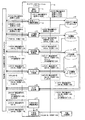
図2は、実施形態に係るネットワークオペレーションシステム10による設定の流れを示す図である。なお、以下では、終端装置としてのGW装置とVPN終端装置との接続(物理的なケーブル又は仮想的なケーブルによる接続)や、図1に示すネットワークの構成は、既に構築済みであることを想定する。
FIG. 2 is a diagram illustrating a setting flow by the
まず概要を説明すると、実施形態に係るネットワークオペレーションシステム10は、複数のクラウド拠点を利用するテナントのために、GW装置とVPN終端装置との間の区間(例えば、4箇所)にVLANの設定を行う。すなわち、実施形態に係るネットワークオペレーションシステム10は、まず、複数のクラウド拠点間を接続する要求を受け付け、クラウド管理部、仮想NW管理部、及びVPN管理部から、VLAN−IDの割り当てに必要な各種情報を収集する。例えば、ネットワークオペレーションシステム10は、クラウド管理部から、仮想マシンに関連する情報(以下、仮想マシン情報)を収集し、また、仮想NW管理部から、終端装置としてのGW装置に関する情報(以下、GW情報)や、VPN終端装置に関する情報(以下、VPN情報)を収集する。続いて、ネットワークオペレーションシステム10は、仮想NW管理部に対して、割り当て可能なVLAN−IDの問い合わせを行い、VLAN−IDを予約する。その後、ネットワークオペレーションシステム10は、設定に必要な各種情報を、予約したVLAN−IDとともに整理し、仮想NW管理部やVPN管理部に対してVLAN−IDの設定をするよう設定指示を行う。
First, the outline will be described. The
更に、実施形態に係るクラウドシステムは、クラウド拠点A内の仮想マシンA−1とクラウド拠点B内の仮想マシンB−2とを、冗長化された第1経路及び第2経路で相互に接続することを想定するので、ネットワークオペレーションシステム10は、この冗長化された第1経路及び第2経路を含むネットワークに生じるループを阻止する設定を行う。
Furthermore, the cloud system according to the embodiment connects the virtual machine A-1 in the cloud base A and the virtual machine B-2 in the cloud base B to each other through the redundant first route and second route. Therefore, the
なお、ネットワークオペレーションシステム10は、一方の経路に切断などの障害が発生した場合には経路の切り替えも実現する(例えば、GW装置及びVPN終端装置に切り替えのための機能を備える)。また、ネットワークオペレーションシステム10は、QoS/SLAの制御も行う。
The
なお、上述した設定の流れや、以下に説明する設定の流れの具体例は一例に過ぎず、例えば、問い合わせ先の管理部や、データベースの構成、問い合わせの順序、設定対象となる装置など、任意に変更することが可能である。ネットワークオペレーションシステム10は、必要な各種情報を収集し、その設定までを完了させることが可能であればよい。
Note that the above-described setting flow and specific examples of the setting flow described below are merely examples. For example, an inquiry destination management unit, a database configuration, an inquiry order, an apparatus to be set, and the like are arbitrary. It is possible to change to The
それでは、図2を用いて設定例を説明する。図2に示すように、ネットワークオペレーションシステム10は、要求受付部11と、仮想マシン情報取得部12と、GW情報取得部13と、VPN情報取得部14と、VLAN−ID予約部15と、VLAN設定部16と、冗長化設定情報取得部17と、冗長化設定部18とを有する。
A setting example will now be described with reference to FIG. As illustrated in FIG. 2, the
要求受付部11は、クラウド拠点間を接続する要求を受け付け、受け付けた要求を仮想マシン情報取得部12に送る。例えば、要求受付部11は、ネットワークオペレーションシステム10の管理者から、クラウド拠点識別子及び仮想マシン名称の指定を受け付け、受け付けたクラウド拠点識別子及び仮想マシン名称を仮想マシン情報取得部12に送る(図2の(1)を参照)。図1の例を用いて説明すると、例えば、要求受付部11は、
クラウド拠点識別子:A
仮想マシン名称:A−1
クラウド拠点識別子:B
仮想マシン名称:B−2
を受け付け、仮想マシン情報取得部12に送る。
The
Cloud base identifier: A
Virtual machine name: A-1
Cloud base identifier: B
Virtual machine name: B-2
Is sent to the virtual machine
仮想マシン情報取得部12は、クラウド管理部に対して仮想マシン情報の問い合わせを行い、クラウド管理部から送られた仮想マシン情報を、仮想マシン情報データベース20に格納する。例えば、仮想マシン情報取得部12は、要求受付部11から送られたクラウド拠点識別子及び仮想マシン名称を用いて、クラウド管理部に対して仮想マシン情報の問い合わせを行う(図2の(2)を参照)。続いて、仮想マシン情報取得部12は、クラウド管理部から、仮想マシンUUID(Universally Unique Identifier)及び仮想NIC(Network Interface Card)UUIDを受け取る(図2の(3)を参照)。そして、仮想マシン情報取得部12は、クラウド拠点識別子及び仮想マシン名称と、仮想マシンUUID及び仮想NIC UUIDとを、仮想マシン情報データベース20に格納する(図2の(4)を参照)。なお、実施形態において、各仮想マシンは、2つの仮想NICを有しており、これらは、各クラウド管理部によって設定されたものである。
The virtual machine
図1の例を用いて説明すると、例えば、仮想マシン情報取得部12は、
クラウド拠点識別子:A
仮想マシン名称:A−1
クラウド拠点識別子:B
仮想マシン名称:B−2
を用いて問い合わせを行い、クラウド管理部Aから、
仮想マシンUUID:M0001
仮想NIC UUID1:NIC0001
仮想NIC UUID2:NIC0015
を受け取り、クラウド管理部Bから、
仮想マシンUUID:M0002
仮想NIC UUID1:NIC0002
仮想NIC UUID2:NIC0025
を受け取り、仮想マシン情報データベース20に、これらの情報を適宜格納する。
If it demonstrates using the example of FIG. 1, the virtual machine
Cloud base identifier: A
Virtual machine name: A-1
Cloud base identifier: B
Virtual machine name: B-2
And make an inquiry from the cloud management department A,
Virtual machine UUID: M0001
Virtual NIC UUID1: NIC0001
Virtual NIC UUID2: NIC0015
From the cloud management department B,
Virtual machine UUID: M0002
Virtual NIC UUID1: NIC0002
Virtual NIC UUID2: NIC0025
Are stored in the virtual
なお、図3は、実施形態に係る仮想マシン情報データベース20を示す図である。図3に示すように、仮想マシン情報データベース20は、仮想マシン情報取得部12によって格納された情報を記憶する。
FIG. 3 is a diagram illustrating the virtual
GW情報取得部13は、仮想NW管理部に対してGW情報の問い合わせを行い、仮想NW管理部から送られたGW情報を、GW情報データベース21に格納する。例えば、GW情報取得部13は、仮想マシン情報データベース20に格納されたクラウド拠点識別子及び仮想NIC UUIDを用いて、仮想NW管理部に対してGW情報の問い合わせを行う(図2の(5)及び(6)を参照)。続いて、GW情報取得部13は、仮想NW管理部から、終端装置としてのGW装置を識別するGW−ID、及び、このGW装置がVPN終端装置と接続する接続ポートである外部ポートIDを受け取る(図2の(7)を参照)。そして、GW情報取得部13は、クラウド拠点識別子及び仮想NIC UUIDと、GW−ID及び外部ポートIDとを、GW情報データベース21に格納する(図2の(8)を参照)。
The GW information acquisition unit 13 inquires about the GW information from the virtual NW management unit, and stores the GW information sent from the virtual NW management unit in the GW information database 21. For example, the GW information acquisition unit 13 uses the cloud base identifier and the virtual NIC UUID stored in the virtual
図1の例を用いて説明すると、例えば、GW情報取得部13は、
クラウド拠点識別子:A
仮想NIC UUID1:NIC0001
仮想NIC UUID2:NIC0015
クラウド拠点識別子:B
仮想NIC UUID1:NIC0002
仮想NIC UUID2:NIC0025
を用いて問い合わせを行い、仮想NW管理部Aから、
GW−ID1:GW100
外部ポートID1:PG100
GW−ID2:GW150
外部ポートID2:PG150
を受け取り、仮想NW管理部Bから、
GW−ID1:GW200
外部ポートID1:PG200
GW−ID2:GW250
外部ポートID2:PG250
を受け取り、GW情報データベース21に、これらの情報を適宜格納する。
If it demonstrates using the example of FIG. 1, the GW information acquisition part 13 will be described, for example.
Cloud base identifier: A
Virtual NIC UUID1: NIC0001
Virtual NIC UUID2: NIC0015
Cloud base identifier: B
Virtual NIC UUID1: NIC0002
Virtual NIC UUID2: NIC0025
Using the virtual NW management unit A,
GW-ID1: GW100
External port ID 1: PG100
GW-ID2: GW150
External port ID2: PG150
From the virtual NW management unit B,
GW-ID1: GW200
External port ID 1: PG200
GW-ID2: GW250
External port ID 2: PG250
Are stored in the GW information database 21 as appropriate.
なお、図4は、実施形態に係るGW情報データベース21を示す図である。図4に示すように、GW情報データベース21は、GW情報取得部13によって格納された情報を記憶する。 FIG. 4 is a diagram illustrating the GW information database 21 according to the embodiment. As illustrated in FIG. 4, the GW information database 21 stores information stored by the GW information acquisition unit 13.
VPN情報取得部14は、仮想NW管理部に対してVPN情報の問い合わせを行い、仮想NW管理部から送られたVPN情報を、VPN情報データベース22に格納する。例えば、VPN情報取得部14は、GW情報データベース21に格納されたクラウド拠点識別子、GW−ID及び外部ポートIDを用いて、仮想NW管理部に対してVPN情報の問い合わせを行う(図2の(9)及び(10)を参照)。続いて、VPN情報取得部14は、仮想NW管理部からVPN終端装置を識別するVPN−ID、及び、このVPN終端装置がGW装置と接続する接続ポートであるVPN接続先ポートIDを受け取る(図2の(11)を参照)。そして、VPN情報取得部14は、クラウド拠点識別子と、GW−IDと、外部ポートIDと、VPN−IDと、VPN接続先ポートIDとを、VPN情報データベース22に格納する(図2の(12)を参照)。
The VPN
図1の例を用いて説明すると、例えば、VPN情報取得部14は、
クラウド拠点識別子:A
GW−ID1:GW100
外部ポートID1:PG100
GW−ID2:GW150
外部ポートID2:PG150
クラウド拠点識別子:B
GW−ID1:GW200
外部ポートID1:PG200
GW−ID2:GW250
外部ポートID2:PG250
を用いて問い合わせを行い、仮想NW管理部Aから、
VPN−ID1:VPN100
VPN接続先ポートID1:VG100
VPN−ID2:VPN150
VPN接続先ポートID2:VG150
を受け取り、仮想NW管理部Bから、
VPN−ID1:VPN200
VPN接続先ポートID1:VG200
VPN−ID2:VPN250
VPN接続先ポートID2:VG250
を受け取り、VPN情報データベース22に、これらの情報を適宜格納する。
If it demonstrates using the example of FIG. 1, the VPN
Cloud base identifier: A
GW-ID1: GW100
External port ID 1: PG100
GW-ID2: GW150
External port ID2: PG150
Cloud base identifier: B
GW-ID1: GW200
External port ID 1: PG200
GW-ID2: GW250
External port ID 2: PG250
Using the virtual NW management unit A,
VPN-ID1: VPN100
VPN connection port ID 1: VG100
VPN-ID2: VPN150
VPN destination port ID2: VG150
From the virtual NW management unit B,
VPN-ID1: VPN200
VPN connection port ID 1: VG200
VPN-ID2: VPN250
VPN connection port ID2: VG250
Are stored in the
なお、図5は、実施形態に係るVPN情報データベース22を示す図である。図5に示すように、VPN情報データベース22は、VPN情報取得部14によって格納された情報を記憶する。
FIG. 5 is a diagram illustrating the
VLAN−ID予約部15は、仮想NW管理部に対して空きのVLAN−IDの問い合わせを行い、仮想NW管理部から送られたVLAN−IDを、VLAN情報データベース23に格納する。例えば、VLAN−ID予約部15は、VPN情報データベース22に格納されたクラウド識別子、GW−ID及び外部ポートIDを用いて、仮想NW管理部に対して空きのVLAN−IDの問い合わせを行う(図2の(13)及び(14)を参照)。続いて、VLAN−ID予約部15は、仮想NW管理部から、割り当て可能なVLAN−IDを受け取る(図2の(15)を参照)。例えば、仮想NW管理部においては、GW−ID及び外部ポートIDの組合せ毎に、VLAN−IDを管理しており、割り当て済みでない空きのVLAN−IDを検索して、VLAN−ID予約部15に送る。そして、VLAN−ID予約部15は、クラウド拠点識別子と、GW−IDと、外部ポートIDと、VLAN−IDとを、VLAN情報データベース23に格納する(図2の(16)を参照)。
The VLAN-
図1の例を用いて説明すると、例えば、VLAN−ID予約部15は、
クラウド拠点識別子:A
GW−ID1:GW100
外部ポートID1:PG100
GW−ID2:GW150
外部ポートID2:PG150
クラウド拠点識別子:B
GW−ID1:GW200
外部ポートID1:PG200
GW−ID2:GW250
外部ポートID2:PG250
を用いて問い合わせを行い、仮想NW管理部Aから、
VLAN−ID1:VLAN1000
VLAN−ID2:VLAN1500
を受け取り、仮想NW管理部Bから、
VLAN−ID1:VLAN2000
VLAN−ID2:VLAN2500
を受け取り、VLAN情報データベース23に、これらの情報を適宜格納する。
If it demonstrates using the example of FIG. 1, the VLAN-
Cloud base identifier: A
GW-ID1: GW100
External port ID 1: PG100
GW-ID2: GW150
External port ID2: PG150
Cloud base identifier: B
GW-ID1: GW200
External port ID 1: PG200
GW-ID2: GW250
External port ID 2: PG250
Using the virtual NW management unit A,
VLAN-ID1: VLAN1000
VLAN-ID2: VLAN1500
From the virtual NW management unit B,
VLAN-ID1: VLAN2000
VLAN-ID2: VLAN 2500
Are stored in the
なお、図6は、実施形態に係るVLAN情報データベース23を示す図である。図6に示すように、VLAN情報データベース23は、VLAN−ID予約部15によって格納された情報を記憶する。
FIG. 6 is a diagram illustrating the
VLAN設定部16は、設定に必要な各種情報を、予約したVLAN−IDとともに整理し、仮想NW管理部やVPN管理部に対してVLAN−IDの設定をするよう、設定指示を行う。例えば、VLAN設定部16は、GW情報データベース21から、クラウド拠点識別子、GW−ID、及び外部ポートIDを読み出し(図2の(17)を参照)、これらをキーにVLAN情報データベース23を検索して、対応するVLAN−IDを読み出す。そして、VLAN設定部16は、該当する仮想NW管理部に対して、クラウド拠点識別子、GW−ID、外部ポートID、及びVLAN−IDを送り、VLAN−IDの設定をするよう、設定指示を行う(図2の(18)を参照)。
The VLAN setting unit 16 organizes various information necessary for setting together with the reserved VLAN-ID, and instructs the virtual NW management unit and the VPN management unit to set the VLAN-ID. For example, the VLAN setting unit 16 reads the cloud base identifier, GW-ID, and external port ID from the GW information database 21 (see (17) in FIG. 2), and searches the
図1の例を用いて説明すると、例えば、VLAN設定部16は、仮想NW管理部Aに対して、
クラウド拠点識別子:A
GW−ID1:GW100
外部ポートID1:PG100
VLAN−ID1:VLAN1000
GW−ID2:GW150
外部ポートID2:PG150
VLAN−ID2:VLAN1500
を送り、設定指示を行い、仮想NW管理部Bに対して、
クラウド拠点識別子:B
GW−ID1:GW200
外部ポートID1:PG200
VLAN−ID1:VLAN2000
GW−ID2:GW250
外部ポートID2:PG250
VLAN−ID2:VLAN2500
を送り、設定指示を行う。
If it demonstrates using the example of FIG. 1, the VLAN setting part 16 will be with respect to the virtual NW management part A, for example.
Cloud base identifier: A
GW-ID1: GW100
External port ID 1: PG100
VLAN-ID1: VLAN1000
GW-ID2: GW150
External port ID2: PG150
VLAN-ID2: VLAN1500
Is sent to the virtual NW management unit B.
Cloud base identifier: B
GW-ID1: GW200
External port ID 1: PG200
VLAN-ID1: VLAN2000
GW-ID2: GW250
External port ID 2: PG250
VLAN-ID2: VLAN 2500
To instruct setting.
また、VLAN設定部16は、VPN情報データベース22から、クラウド拠点識別子、GW−ID、外部ポートID、VPN−ID、及びVPN接続先ポートIDを読み出し(図2の(19)を参照)、これらをキーにVLAN情報データベース23を検索して、対応するVLAN−IDを読み出す。そして、VLAN設定部16は、該当するVPN管理部に対して、クラウド拠点識別子、VPN−ID、VPN接続先ポートID、及びVLAN−IDを送り、VLAN−IDの設定をするよう、設定指示を行う(図2の(20)を参照)。
Further, the VLAN setting unit 16 reads out the cloud base identifier, GW-ID, external port ID, VPN-ID, and VPN connection destination port ID from the VPN information database 22 (see (19) in FIG. 2). The key is used to search the
図1の例を用いて説明すると、例えば、VLAN設定部16は、VPN管理部に対し、
クラウド拠点識別子:A
VPN−ID1:VPN100
VPN接続先ポートID1:VG100
VLAN−ID1:VLAN1000
VPN−ID2:VPN150
VPN接続先ポートID2:VG150
VLAN−ID2:VLAN1500
を送り、設定指示を行うとともに、
クラウド拠点識別子:B
VPN−ID1:VPN200
VPN接続先ポートID1:VG200
VLAN−ID1:VLAN2000
VPN−ID2:VPN250
VPN接続先ポートID2:VG250
VLAN−ID2:VLAN2500
を送り、設定指示を行う。
If it demonstrates using the example of FIG. 1, for example, the VLAN setting part 16 will be with respect to a VPN management part.
Cloud base identifier: A
VPN-ID1: VPN100
VPN connection port ID 1: VG100
VLAN-ID1: VLAN1000
VPN-ID2: VPN150
VPN destination port ID2: VG150
VLAN-ID2: VLAN1500
And give instructions for setting,
Cloud base identifier: B
VPN-ID1: VPN200
VPN connection port ID 1: VG200
VLAN-ID1: VLAN2000
VPN-ID2: VPN250
VPN connection port ID2: VG250
VLAN-ID2: VLAN 2500
To instruct setting.
冗長化設定情報取得部17は、仮想NW管理部又はVPN管理部に対して、冗長化されたネットワークに生じるループを阻止する設定(STP(Spanning Tree Protocol)によるブロッキングポイントの設定)を行う場所を問い合わせ、問い合わせた内容を、冗長化設定部18に送る。ブロッキングポイントの設定とは、例えば、GW装置とVPN終端装置との間に監視装置を挿入し、監視装置に、ループの発生を検知してパケットの転送を中止させる機能を組み込むことである。また、例えば、GW装置やVPN終端装置に同様の機能を設定することである。以下では、GW装置に同様の機能を設定する例を説明する。 The redundancy setting information acquisition unit 17 sets a place for performing setting (blocking point setting by STP (Spanning Tree Protocol)) that prevents a loop generated in the redundant network to the virtual NW management unit or the VPN management unit. The inquiry and the contents of the inquiry are sent to the redundancy setting unit 18. The setting of the blocking point is, for example, that a monitoring device is inserted between the GW device and the VPN terminating device, and a function for detecting the occurrence of a loop and stopping packet transfer is incorporated in the monitoring device. For example, the same function is set in the GW apparatus or the VPN termination apparatus. Below, the example which sets the same function to GW apparatus is demonstrated.
図7は、実施形態におけるブロッキングポイントの設定を説明するための図である。ブロッキングポイントは、クラウド拠点A側のGW装置100とVPN終端装置300との接続、クラウド拠点B側のGW装置200とVPN終端装置400との接続、クラウド拠点A側のGW装置150とVPN終端装置350との接続、及び、クラウド拠点B側のGW装置250とVPN終端装置450との接続のうち、少なくとも1つの接続に対して設定されればよい。
FIG. 7 is a diagram for explaining setting of a blocking point in the embodiment. The blocking points are the connection between the
例えば、仮想NW管理部又はVPN管理部は、ブロッキングポイントの設定を行う場所を示す冗長化設定情報として、「{クラウド拠点識別子,GW−ID,外部ポートID},冗長設定フラグ、設定先,装置ID又は装置アドレス」を管理している。例えば、仮想NW管理部又はVPN管理部は、「{A,GW150,*},1,2,10.0.0.5」を管理している。これは、クラウド拠点Aに設置されたGW装置150に(外部ポートIDはワイルドカード)、ブロッキングポイントを設定すべきであることを示す。また、冗長設定フラグは、GW装置とVPN終端装置とが分離型(物理的なケーブルで接続)である場合に「1」であり、一体型(仮想的なケーブルで接続)である場合に「2」である。また、設定先は、設定対象が仮想NW管理部又はVPN管理部に対する設定指示の場合には「1」、GW装置やVPN終端装置に対する直接の設定指示の場合には「2」である。また、装置ID又は装置アドレスは、設定先の装置(仮想NW管理部又はVPN管理部、あるいは、GW装置又はVPN終端装置)を識別するIDやIP(Internet Protocol)アドレスである。
For example, the virtual NW management unit or the VPN management unit uses “{cloud base identifier, GW-ID, external port ID}, redundancy setting flag, setting destination, device as redundancy setting information indicating a place where a blocking point is set. ID or device address "is managed. For example, the virtual NW management unit or the VPN management unit manages “{A, GW150, *}, 1, 2, 10.0.0.5”. This indicates that a blocking point should be set in the
例えば、冗長化設定情報取得部17は、該当する仮想NW管理部又はVPN管理部に対して、クラウド拠点識別子及びGW−IDを送り、ブロッキングポイントの設定を行う場所を問い合わせる(図2の(21)を参照)。すると、仮想NW管理部又はVPN管理部は、クラウド拠点識別子、GW−ID、及び外部ポートIDを含む冗長化設定情報を、冗長化設定情報取得部17に送る(図2の(22)を参照)。 For example, the redundancy setting information acquisition unit 17 sends the cloud base identifier and the GW-ID to the corresponding virtual NW management unit or VPN management unit, and inquires about the location where the blocking point is set ((21 in FIG. 2). )). Then, the virtual NW management unit or the VPN management unit sends the redundancy setting information including the cloud base identifier, the GW-ID, and the external port ID to the redundancy setting information acquisition unit 17 (see (22) in FIG. 2). ).
図7の例を用いて説明すると、例えば、冗長化設定情報取得部17は、仮想NW管理部A、仮想NW管理部B又はVPN管理部に対し、
クラウド拠点識別子:A
GW−ID1:GW100
GW−ID2:GW150
クラウド拠点識別子:B
GW−ID1:GW200
GW−ID2:GW250
を送り、ブロッキングポイントの設定を行う場所を問い合わせ、仮想NW管理部A、仮想NW管理部B又はVPN管理部から、冗長化設定情報として、
{A,GW150,*},1,2,10.0.0.5
を受け取る。例えば、仮想NW管理部A、仮想NW管理部B又はVPN管理部は、ブロッキングポイントとして設定可能な場所をGW−IDを用いて検索し、該当するGW−IDが含まれる冗長化情報を、冗長化設定情報取得部17に送る。複数の冗長化情報が検索された場合には、仮想NW管理部A、仮想NW管理部B又はVPN管理部は、適宜選択して冗長化設定情報取得部17に送ってもよい。
If it demonstrates using the example of FIG. 7, the redundancy setting information acquisition part 17 will be with respect to the virtual NW management part A, the virtual NW management part B, or the VPN management part, for example.
Cloud base identifier: A
GW-ID1: GW100
GW-ID2: GW150
Cloud base identifier: B
GW-ID1: GW200
GW-ID2: GW250
As a redundant setting information from the virtual NW management unit A, the virtual NW management unit B or the VPN management unit.
{A, GW150, *}, 1, 2, 10.0.0.5
Receive. For example, the virtual NW management unit A, the virtual NW management unit B, or the VPN management unit searches for a place that can be set as a blocking point by using the GW-ID, and makes redundant information including the corresponding GW-ID redundant. Sent to the setup information acquisition unit 17. When a plurality of redundancy information is searched, the virtual NW management unit A, the virtual NW management unit B, or the VPN management unit may be appropriately selected and sent to the redundancy setting information acquisition unit 17.
なお、上述の例では、外部ポートIDはワイルドカードとなっており、特定のGW装置であれば、外部ポートに限らず常にブロッキングポイントの設定対象となる例を示したが、実施形態はこれに限られるものではない。例えば、外部ポートの単位で細かくブロッキングポイントの設定場所が制御される場合、仮想NW管理部又はVPN管理部は、外部ポートIDまで具体的に記述した冗長化設定情報を管理し、例えば、リストの状態で冗長化設定情報取得部17に送ってもよい。例えば、仮想NW管理部又はVPN管理部は、
{A,GW150,PG550},1,2,10.0.0.5
{A,GW150,PG650},1,2,10.0.0.5
{B,GW250,PG250},1,2,10.0.0.5
{B,GW250,PG350},1,2,10.0.0.5
といったリストを冗長化設定情報取得部17に送ってもよい。なお、上述のリストの例の場合、設定可能なブロッキングポイントは、クラウド拠点BのGW装置250となる。
In the above-described example, the external port ID is a wild card, and, as long as it is a specific GW device, an example in which a blocking point is always set is shown in addition to the external port. It is not limited. For example, when the blocking point setting location is finely controlled in units of external ports, the virtual NW management unit or VPN management unit manages the redundant setting information specifically described up to the external port ID. You may send to the redundant setting information acquisition part 17 in a state. For example, the virtual NW management unit or the VPN management unit
{A, GW150, PG550}, 1, 2, 10.0.0.5
{A, GW150, PG650}, 1, 2, 10.0.0.5
{B, GW250, PG250}, 1, 2, 10.0.0.5
{B, GW250, PG350}, 1, 2, 10.0.0.5
Such a list may be sent to the redundancy setting information acquisition unit 17. In the case of the above-described list example, the settable blocking point is the
冗長化設定部18は、冗長化設定情報取得部17から受け取った冗長化設定情報に基づいて、ブロッキングポイントの設定を行う。例えば、冗長化設定部18は、冗長化設定情報として、
{A,GW150,*},1,2,10.0.0.5
を受け取ると、
・クラウド拠点AのGW装置150にブロッキングポイントの設定をすべきこと、
・GW装置とVPN終端装置とが分離型(物理的なケーブルで接続)であること、
・設定先は、GW装置に対する直接の設定指示であること、
・GW装置のIPアドレスは「10.0.0.5」であること、
を把握する。そして、冗長化設定部18は、IPアドレス「10.0.0.5」のGW150に対して、外部ポートID「PG150」を指定し、直接、ブロッキングポイントの設定指示を行う。
The redundancy setting unit 18 sets a blocking point based on the redundancy setting information received from the redundancy setting information acquisition unit 17. For example, the redundancy setting unit 18 includes the redundancy setting information as
{A, GW150, *}, 1, 2, 10.0.0.5
When you receive
-A blocking point should be set for the
-The GW device and the VPN terminator are separated (connected with a physical cable),
-The setting destination is a direct setting instruction to the GW device.
-The IP address of the GW device is "10.0.0.5"
To figure out. Then, the redundancy setting unit 18 designates the external port ID “PG150” for the
なお、VLAN設定部16や冗長化設定部18による設定指示には、例えば、アタッチメントが用いられる。アタッチメントとは、例えば、VLAN−IDを設定するためのプログラムや、ブロッキングポイントを設定するためのプログラムなどである。アタッチメントには、ネットワークオペレーションシステム10と、仮想NW管理部やVPN管理部、GW装置などとの間で用いられる通信プロトコルが規定される。なお、一般に、この通信プロトコルには、各装置のベンダによって規定される独自仕様の通信プロトコルが用いられる。また、アタッチメントには、例えば、ネットワークオペレーションシステム10から各装置に対してtelnetやSSH(Secure SHell)などを用いて遠隔操作することにより、各種情報を設定する手法が含まれていてもよい。
For example, an attachment is used for the setting instruction by the VLAN setting unit 16 or the redundancy setting unit 18. The attachment is, for example, a program for setting a VLAN-ID, a program for setting a blocking point, or the like. In the attachment, a communication protocol used between the
上述してきたように、実施形態に係るクラウドシステムによれば、VLAN−IDが一意に割り当てられるべき範囲が局所化される結果、VLAN−IDの枯渇を改善することができる。また、実施形態に係るクラウドシステムによれば、VLAN−IDは、局所化された範囲内でのみ一意に割り当てられればよいので、自由度が向上し、その調整の手間も低減され、ひいては、VLAN−IDの割り当てを自動化することも可能になる。 As described above, according to the cloud system according to the embodiment, as a result of localizing the range to which the VLAN-ID is uniquely assigned, it is possible to improve the depletion of the VLAN-ID. In addition, according to the cloud system according to the embodiment, the VLAN-ID only needs to be uniquely assigned within a localized range, so that the degree of freedom is improved and the effort of adjustment is reduced. -It is also possible to automate ID assignment.
また、実施形態に係るネットワークオペレーションシステム10によれば、物理的なネットワークの情報や仮想的なネットワークの情報を集めて一元管理することで、設定の手間を低減し、VLAN−IDの割り当てを効率的に自動化することが可能である。
In addition, according to the
[他の実施形態]
なお、上述したゲートウェイ装置100、ゲートウェイ装置150、ゲートウェイ装置200、及びゲートウェイ装置250や、ネットワークオペレーションシステム10は、上述した実施形態以外にも、種々の異なる形態にて実施されてよい。
[Other Embodiments]
The
例えば、上述した実施形態に係るゲートウェイ装置100、ゲートウェイ装置150、ゲートウェイ装置200、及びゲートウェイ装置250や、ネットワークオペレーションシステム10が実行する処理を、コンピュータが実行可能な言語で記述したプログラムを作成することもできる。この場合、コンピュータがプログラムを実行することにより、上述した実施形態と同様の効果を得ることができる。更に、かかるプログラムをコンピュータ読み取り可能な記録媒体に記録して、この記録媒体に記録されたプログラムをコンピュータに読み込ませて実行することにより、上述の実施形態と同様の処理を実現してもよい。以下、図1に示したゲートウェイ装置100と同様の機能を実現するプログラムを実行するコンピュータの一例を説明する。
For example, creating a program describing the processing executed by the
図8は、ゲートウェイ装置100と同様の機能を実現するプログラムを実行するコンピュータを示す図である。図8に示すように、コンピュータは、例えば、メモリと、CPU(Central Processing Unit)と、ハードディスクドライブインタフェースと、ディスクドライブインタフェースと、シリアルポートインタフェースと、ビデオアダプタと、ネットワークインタフェースとを有し、これらの各部はバスによって接続される。
FIG. 8 is a diagram illustrating a computer that executes a program that implements the same function as that of the
メモリは、図8に示すように、ROM(Read Only Memory)及びRAM(Random Access Memory)を含む。ROMは、例えば、BIOS(Basic Input Output System)などのブートプログラムを記憶する。ハードディスクドライブインタフェースは、図8に示すように、ハードディスクドライブに接続される。ディスクドライブインタフェースは、図8に示すように、ディスクドライブに接続される。例えば磁気ディスクや光ディスクなどの着脱可能な記憶媒体が、ディスクドライブに挿入される。シリアルポートインタフェースは、図8に示すように、例えばマウス、キーボードに接続される。ビデオアダプタは、図8に示すように、例えばディスプレイに接続される。 As shown in FIG. 8, the memory includes a ROM (Read Only Memory) and a RAM (Random Access Memory). The ROM stores, for example, a boot program such as BIOS (Basic Input Output System). The hard disk drive interface is connected to the hard disk drive as shown in FIG. The disk drive interface is connected to the disk drive as shown in FIG. For example, a removable storage medium such as a magnetic disk or an optical disk is inserted into the disk drive. As shown in FIG. 8, the serial port interface is connected to a mouse and a keyboard, for example. As shown in FIG. 8, the video adapter is connected to a display, for example.
ここで、図8に示すように、ハードディスクドライブは、例えば、OS(Operating System)、アプリケーションプログラム、プログラムモジュール、プログラムデータを記憶する。すなわち、上述のプログラムは、コンピュータによって実行される指令が記述されたプログラムモジュールとして、例えばハードディスクドライブに記憶される。例えば、「VPN終端装置300との間でパケットを送受信する場合に、テナント単位に割り当てられたVLAN−IDを用いて送受信する第1送受信手順」と、「クラウド拠点Aのネットワーク内でパケットを転送するゲートウェイ装置110との間でパケットを送受信する場合に、VLAN−IDとは異なる識別情報を用いて送受信する第2送受信手順」とが記述されたプログラムモジュールが、ハードディスクドライブに記憶される。
Here, as shown in FIG. 8, the hard disk drive stores, for example, an OS (Operating System), application programs, program modules, and program data. That is, the above-described program is stored in, for example, a hard disk drive as a program module in which a command to be executed by a computer is described. For example, “when transmitting / receiving a packet to / from the
また、上述した実施形態で説明したゲートウェイ装置100が保持する各種データは、プログラムデータとして、例えばメモリやハードディスクドライブに記憶される。そして、CPUが、メモリやハードディスクドライブに記憶されたプログラムモジュールやプログラムデータを必要に応じてRAMに読み出し、各手順を実行する。
Various data held by the
なお、上述のプログラムに係るプログラムモジュールやプログラムデータは、ハードディスクドライブに記憶される場合に限られず、例えば着脱可能な記憶媒体に記憶され、ディスクドライブなどを介してCPUによって読み出されてもよい。あるいは、上述のプログラムに係るプログラムモジュールやプログラムデータは、ネットワーク(LAN(Local Area Network)、WAN(Wide Area Network)など)を介して接続された他のコンピュータに記憶され、ネットワークインタフェースを介してCPUによって読み出されてもよい。 Note that the program modules and program data related to the above-described program are not limited to being stored in the hard disk drive, but may be stored in, for example, a removable storage medium and read by the CPU via the disk drive or the like. Alternatively, the program module and program data related to the above-described program are stored in another computer connected via a network (LAN (Local Area Network), WAN (Wide Area Network), etc.), and the CPU is connected to the CPU via the network interface. May be read.
10 ネットワークオペレーションシステム
100 GW装置
150 GW装置
200 GW装置
250 GW装置
300 VPN終端装置
350 VPN終端装置
400 VPN終端装置
450 VPN終端装置
DESCRIPTION OF
Claims (6)
前記クラウド拠点に設けられ、テナントの端末からの要求に応じてサービスを提供する仮想マシンと、
前記クラウド拠点に設けられ、前記仮想マシンに接続されて、該仮想マシンと前記端末との間で送受信されるパケットを、自クラウド拠点のネットワーク内で転送する転送装置と、
前記クラウド拠点に設けられ、前記転送装置と、前記VPNを前記クラウド拠点側で終端するVPN終端装置とに接続されて、該自クラウド拠点のネットワークを終端するゲートウェイ装置とを備え、
前記転送装置は、前記テナント単位に割り当てられたVLAN(Virtual Local Area Network)を識別する、VLAN−ID(VLAN-Identifier)とは異なるVLAN識別情報を用いてパケットを転送し、
前記ゲートウェイ装置は、前記VPN終端装置との間では、前記VLAN−IDを用いてパケットを送受信し、前記転送装置との間では、前記VLAN識別情報を用いてパケットを送受信し、
前記VLAN−IDは、前記ゲートウェイ装置及び前記VPN終端装置の接続区間ごとに、一意に割り当てられる
ことを特徴とするクラウドシステム。 A cloud system that connects multiple cloud sites by connecting cloud sites to each other via a VPN (Virtual Private Network),
A virtual machine provided at the cloud base and providing a service in response to a request from a tenant's terminal;
A transfer device provided at the cloud base, connected to the virtual machine and transmitting / receiving a packet transmitted / received between the virtual machine and the terminal within the network of the own cloud base;
Provided in the cloud base, and connected to the transfer device and a VPN terminator for terminating the VPN on the cloud base side, and a gateway device for terminating the network of the cloud base,
The transfer device transfers a packet using VLAN identification information different from a VLAN-ID (VLAN-Identifier) that identifies a VLAN (Virtual Local Area Network) allocated to each tenant unit,
The gateway device transmits / receives a packet using the VLAN-ID to / from the VPN terminating device, and transmits / receives a packet to / from the transfer device using the VLAN identification information ,
The VLAN-ID is uniquely assigned for each connection section of the gateway device and the VPN termination device.
Cloud system comprising a call.
第1クラウド拠点内の仮想マシンと第2クラウド拠点内の仮想マシンとを冗長化された第1経路及び第2経路で相互に接続するものであって、
前記第1経路及び前記第2経路を含むネットワークに生じるループを阻止する設定を、前記第1経路に含まれる第1クラウド拠点側のゲートウェイ装置とVPN終端装置との接続、前記第1経路に含まれる第2クラウド拠点側のゲートウェイ装置とVPN終端装置との接続、前記第2経路に含まれる第1クラウド拠点側のゲートウェイ装置とVPN終端装置との接続、及び、前記第2経路に含まれる第2クラウド拠点側のゲートウェイ装置とVPN終端装置との接続のうち、少なくとも1つの接続に対して設定することを特徴とする請求項1又は2に記載のクラウドシステム。 The cloud system
The virtual machine in the first cloud base and the virtual machine in the second cloud base are connected to each other by the redundant first route and second route,
A setting for preventing a loop generated in the network including the first route and the second route is included in the connection between the gateway device on the first cloud base side and the VPN termination device included in the first route, and the first route. A connection between the gateway device on the second cloud base side and the VPN termination device, a connection between the gateway device on the first cloud base side and the VPN termination device included in the second route, and a second included in the second route. 3. The cloud system according to claim 1, wherein the cloud system is set for at least one connection among connections between the gateway device on the cloud base side and the VPN termination device.
前記VPN終端装置との間でパケットを送受信する場合に、テナント単位に割り当てられたVLANを識別するVLAN−ID(VLAN-Identifier)を用いて送受信する第1送受信部と、
前記クラウド拠点のネットワーク内でパケットを転送する転送装置との間でパケットを送受信する場合に、前記VLAN−IDとは異なるVLAN識別情報を用いて送受信する第2送受信部と
を備え、
前記VLAN−IDは、前記ゲートウェイ装置及び前記VPN終端装置の接続区間ごとに、一意に割り当てられる
ことを特徴とするゲートウェイ装置。 A gateway that terminates a network at a cloud base by connecting to a VPN terminator that terminates the VPN at the cloud base when the cloud bases are connected to each other via a VPN. A device,
A first transmission / reception unit that transmits / receives a VLAN-ID (VLAN-Identifier) that identifies a VLAN assigned to each tenant when transmitting / receiving a packet to / from the VPN termination device;
A second transmission / reception unit that transmits / receives a packet using a VLAN identification information different from the VLAN -ID when transmitting / receiving a packet to / from a transfer device that transfers the packet in the cloud base network ,
The VLAN-ID is uniquely assigned for each connection section of the gateway device and the VPN termination device.
Gateway device comprising a call.
前記通信制御方法は、
前記VPN終端装置との間でパケットを送受信する場合に、テナント単位に割り当てられたVLANを識別するVLAN−ID(VLAN-Identifier)を用いて送受信する第1送受信工程と、
前記クラウド拠点のネットワーク内でパケットを転送する転送装置との間でパケットを送受信する場合に、前記VLAN−IDとは異なるVLAN識別情報を用いて送受信する第2送受信工程と
を含み、
前記VLAN−IDは、前記ゲートウェイ装置及び前記VPN終端装置の接続区間ごとに、一意に割り当てられる
ことを特徴とする通信制御方法。 A gateway that terminates a network at a cloud base by connecting to a VPN terminator that terminates the VPN at the cloud base when the cloud bases are connected to each other via a VPN. A communication control method executed by an apparatus,
The communication control method includes:
A first transmission / reception step of transmitting / receiving using a VLAN-ID (VLAN-Identifier) for identifying a VLAN assigned to each tenant when transmitting / receiving a packet to / from the VPN termination device;
When sending and receiving packets to and from the transfer device for transferring packets within the network of the cloud base, seen including a second receiving step of receiving with different VLAN identification information and the VLAN-ID,
The VLAN-ID is uniquely assigned for each connection section of the gateway device and the VPN termination device.
Communication control method according to claim and this.
Priority Applications (1)
| Application Number | Priority Date | Filing Date | Title |
|---|---|---|---|
| JP2012024446A JP5679343B2 (en) | 2012-02-07 | 2012-02-07 | Cloud system, gateway device, communication control method, and communication control program |
Applications Claiming Priority (1)
| Application Number | Priority Date | Filing Date | Title |
|---|---|---|---|
| JP2012024446A JP5679343B2 (en) | 2012-02-07 | 2012-02-07 | Cloud system, gateway device, communication control method, and communication control program |
Publications (2)
| Publication Number | Publication Date |
|---|---|
| JP2013162418A JP2013162418A (en) | 2013-08-19 |
| JP5679343B2 true JP5679343B2 (en) | 2015-03-04 |
Family
ID=49174316
Family Applications (1)
| Application Number | Title | Priority Date | Filing Date |
|---|---|---|---|
| JP2012024446A Expired - Fee Related JP5679343B2 (en) | 2012-02-07 | 2012-02-07 | Cloud system, gateway device, communication control method, and communication control program |
Country Status (1)
| Country | Link |
|---|---|
| JP (1) | JP5679343B2 (en) |
Cited By (2)
| Publication number | Priority date | Publication date | Assignee | Title |
|---|---|---|---|---|
| CN108781178A (en) * | 2016-03-02 | 2018-11-09 | 日本电气株式会社 | Network system, control device, the construction method of virtual network function and program |
| EP4170981A1 (en) | 2021-10-19 | 2023-04-26 | Yokogawa Electric Corporation | Control system, control method, and non-transitory computer readable storage medium |
Families Citing this family (6)
| Publication number | Priority date | Publication date | Assignee | Title |
|---|---|---|---|---|
| JP2014075731A (en) * | 2012-10-05 | 2014-04-24 | Hitachi Solutions Ltd | Intercloud communication-setting system |
| JP6256591B2 (en) | 2014-03-14 | 2018-01-10 | 日本電気株式会社 | Communication apparatus and traffic control method |
| WO2016110897A1 (en) * | 2015-01-09 | 2016-07-14 | 日本電気株式会社 | Communication system, communication device, communication method and control program |
| JP6317042B2 (en) * | 2015-07-24 | 2018-04-25 | 株式会社日立製作所 | Data center linkage system and method |
| US11438417B2 (en) | 2016-03-02 | 2022-09-06 | Nec Corporation | Network system, terminal, sensor data collection method, and program |
| JP6579257B2 (en) * | 2016-03-02 | 2019-09-25 | 日本電気株式会社 | Network system, control device, virtual network construction method and program |
Family Cites Families (2)
| Publication number | Priority date | Publication date | Assignee | Title |
|---|---|---|---|---|
| CN101146016B (en) * | 2006-09-15 | 2010-07-07 | 华为技术有限公司 | Ethernet frame transmission method and Ethernet architecture |
| CA2797278A1 (en) * | 2010-05-03 | 2011-11-10 | Brocade Communications Systems, Inc. | Virtual cluster switching |
-
2012
- 2012-02-07 JP JP2012024446A patent/JP5679343B2/en not_active Expired - Fee Related
Cited By (3)
| Publication number | Priority date | Publication date | Assignee | Title |
|---|---|---|---|---|
| CN108781178A (en) * | 2016-03-02 | 2018-11-09 | 日本电气株式会社 | Network system, control device, the construction method of virtual network function and program |
| CN108781178B (en) * | 2016-03-02 | 2021-12-28 | 日本电气株式会社 | Network system, control device, method for constructing virtual network function, and program |
| EP4170981A1 (en) | 2021-10-19 | 2023-04-26 | Yokogawa Electric Corporation | Control system, control method, and non-transitory computer readable storage medium |
Also Published As
| Publication number | Publication date |
|---|---|
| JP2013162418A (en) | 2013-08-19 |
Similar Documents
| Publication | Publication Date | Title |
|---|---|---|
| US11646964B2 (en) | System, apparatus and method for providing a virtual network edge and overlay with virtual control plane | |
| JP5679343B2 (en) | Cloud system, gateway device, communication control method, and communication control program | |
| US20230224246A1 (en) | System, apparatus and method for providing a virtual network edge and overlay with virtual control plane | |
| EP3522485B1 (en) | Application-aware firewall policy enforcement by data center controller | |
| US11184842B2 (en) | Conveying non-access stratum messages over ethernet | |
| US10389542B2 (en) | Multicast helper to link virtual extensible LANs | |
| US9124485B2 (en) | Topology aware provisioning in a software-defined networking environment | |
| EP2840743B1 (en) | Method and system for realizing virtual network | |
| EP3152865B1 (en) | Provisioning and managing slices of a consumer premises equipment device | |
| US11398956B2 (en) | Multi-Edge EtherChannel (MEEC) creation and management | |
| EP2731313B1 (en) | Distributed cluster processing system and message processing method thereof | |
| US9444723B1 (en) | Passing data over virtual links | |
| CN103580980A (en) | Automatic searching and automatic configuration method and device of VN | |
| EP3289728B1 (en) | Distribution of internal routes for virtual networking | |
| US9967140B2 (en) | Virtual links for network appliances | |
| EP3817293B1 (en) | Bulk discovery of devices behind a network address translation device | |
| CN112385194B (en) | State packet transmission between remote networks | |
| KR101729944B1 (en) | Method for supplying ip address by multi tunant network system based on sdn | |
| US9794146B2 (en) | Methods and systems for a monitoring device to execute commands on an attached switch | |
| CN112671811B (en) | Network access method and equipment | |
| JP5063726B2 (en) | Configuration control method for virtual node device | |
| EP3817341B1 (en) | Bulk configuration of devices behind a network address translation device | |
| KR101729945B1 (en) | Method for supporting multi tunant by network system based on sdn | |
| KR20170006950A (en) | Network flattening system based on sdn and method thereof | |
| KR101806376B1 (en) | Multi tunant network system based on sdn capable of supplying ip address |
Legal Events
| Date | Code | Title | Description |
|---|---|---|---|
| A621 | Written request for application examination |
Free format text: JAPANESE INTERMEDIATE CODE: A621 Effective date: 20140115 |
|
| A977 | Report on retrieval |
Free format text: JAPANESE INTERMEDIATE CODE: A971007 Effective date: 20140901 |
|
| A131 | Notification of reasons for refusal |
Free format text: JAPANESE INTERMEDIATE CODE: A131 Effective date: 20140909 |
|
| A521 | Request for written amendment filed |
Free format text: JAPANESE INTERMEDIATE CODE: A523 Effective date: 20141029 |
|
| TRDD | Decision of grant or rejection written | ||
| A01 | Written decision to grant a patent or to grant a registration (utility model) |
Free format text: JAPANESE INTERMEDIATE CODE: A01 Effective date: 20141224 |
|
| A61 | First payment of annual fees (during grant procedure) |
Free format text: JAPANESE INTERMEDIATE CODE: A61 Effective date: 20141225 |
|
| R150 | Certificate of patent or registration of utility model |
Ref document number: 5679343 Country of ref document: JP Free format text: JAPANESE INTERMEDIATE CODE: R150 |
|
| LAPS | Cancellation because of no payment of annual fees |