EP3201122B1 - Micromachined ultrasonic transducers with a slotted membrane structure - Google Patents
Micromachined ultrasonic transducers with a slotted membrane structure Download PDFInfo
- Publication number
- EP3201122B1 EP3201122B1 EP15846584.9A EP15846584A EP3201122B1 EP 3201122 B1 EP3201122 B1 EP 3201122B1 EP 15846584 A EP15846584 A EP 15846584A EP 3201122 B1 EP3201122 B1 EP 3201122B1
- Authority
- EP
- European Patent Office
- Prior art keywords
- cantilevers
- membrane
- substrate
- pmut
- layer
- Prior art date
- Legal status (The legal status is an assumption and is not a legal conclusion. Google has not performed a legal analysis and makes no representation as to the accuracy of the status listed.)
- Active
Links
- 239000012528 membrane Substances 0.000 title claims description 58
- 239000000758 substrate Substances 0.000 claims description 23
- 238000000034 method Methods 0.000 claims description 9
- 239000000463 material Substances 0.000 claims description 8
- 238000013461 design Methods 0.000 description 13
- 230000035945 sensitivity Effects 0.000 description 6
- 229910052710 silicon Inorganic materials 0.000 description 6
- 239000010703 silicon Substances 0.000 description 6
- 238000006073 displacement reaction Methods 0.000 description 5
- 238000005530 etching Methods 0.000 description 5
- 229910052751 metal Inorganic materials 0.000 description 5
- 239000002184 metal Substances 0.000 description 5
- XUIMIQQOPSSXEZ-UHFFFAOYSA-N Silicon Chemical compound [Si] XUIMIQQOPSSXEZ-UHFFFAOYSA-N 0.000 description 4
- 229910052782 aluminium Inorganic materials 0.000 description 3
- 238000004519 manufacturing process Methods 0.000 description 3
- 238000012986 modification Methods 0.000 description 3
- 230000004048 modification Effects 0.000 description 3
- 229910052750 molybdenum Inorganic materials 0.000 description 3
- 238000004088 simulation Methods 0.000 description 3
- 230000003068 static effect Effects 0.000 description 3
- 238000010276 construction Methods 0.000 description 2
- 230000008878 coupling Effects 0.000 description 2
- 238000010168 coupling process Methods 0.000 description 2
- 238000005859 coupling reaction Methods 0.000 description 2
- 238000000708 deep reactive-ion etching Methods 0.000 description 2
- 230000000694 effects Effects 0.000 description 2
- HFGPZNIAWCZYJU-UHFFFAOYSA-N lead zirconate titanate Chemical compound [O-2].[O-2].[O-2].[O-2].[O-2].[Ti+4].[Zr+4].[Pb+2] HFGPZNIAWCZYJU-UHFFFAOYSA-N 0.000 description 2
- 229910052451 lead zirconate titanate Inorganic materials 0.000 description 2
- 150000002739 metals Chemical class 0.000 description 2
- 239000011733 molybdenum Substances 0.000 description 2
- 239000002033 PVDF binder Substances 0.000 description 1
- 229910052581 Si3N4 Inorganic materials 0.000 description 1
- VYPSYNLAJGMNEJ-UHFFFAOYSA-N Silicium dioxide Chemical compound O=[Si]=O VYPSYNLAJGMNEJ-UHFFFAOYSA-N 0.000 description 1
- 238000013459 approach Methods 0.000 description 1
- 230000003190 augmentative effect Effects 0.000 description 1
- 229910052802 copper Inorganic materials 0.000 description 1
- 230000007423 decrease Effects 0.000 description 1
- 230000001419 dependent effect Effects 0.000 description 1
- 230000006870 function Effects 0.000 description 1
- 239000011521 glass Substances 0.000 description 1
- 229910052737 gold Inorganic materials 0.000 description 1
- 230000003287 optical effect Effects 0.000 description 1
- ZBSCCQXBYNSKPV-UHFFFAOYSA-N oxolead;oxomagnesium;2,4,5-trioxa-1$l^{5},3$l^{5}-diniobabicyclo[1.1.1]pentane 1,3-dioxide Chemical compound [Mg]=O.[Pb]=O.[Pb]=O.[Pb]=O.O1[Nb]2(=O)O[Nb]1(=O)O2 ZBSCCQXBYNSKPV-UHFFFAOYSA-N 0.000 description 1
- 229920000642 polymer Polymers 0.000 description 1
- 229920000307 polymer substrate Polymers 0.000 description 1
- 229920002981 polyvinylidene fluoride Polymers 0.000 description 1
- 238000011160 research Methods 0.000 description 1
- HQVNEWCFYHHQES-UHFFFAOYSA-N silicon nitride Chemical compound N12[Si]34N5[Si]62N3[Si]51N64 HQVNEWCFYHHQES-UHFFFAOYSA-N 0.000 description 1
- 229910052814 silicon oxide Inorganic materials 0.000 description 1
- 239000010409 thin film Substances 0.000 description 1
- 230000026683 transduction Effects 0.000 description 1
- 238000010361 transduction Methods 0.000 description 1
- 238000002604 ultrasonography Methods 0.000 description 1
Images


Classifications
-
- B—PERFORMING OPERATIONS; TRANSPORTING
- B06—GENERATING OR TRANSMITTING MECHANICAL VIBRATIONS IN GENERAL
- B06B—METHODS OR APPARATUS FOR GENERATING OR TRANSMITTING MECHANICAL VIBRATIONS OF INFRASONIC, SONIC, OR ULTRASONIC FREQUENCY, e.g. FOR PERFORMING MECHANICAL WORK IN GENERAL
- B06B1/00—Methods or apparatus for generating mechanical vibrations of infrasonic, sonic, or ultrasonic frequency
- B06B1/02—Methods or apparatus for generating mechanical vibrations of infrasonic, sonic, or ultrasonic frequency making use of electrical energy
- B06B1/06—Methods or apparatus for generating mechanical vibrations of infrasonic, sonic, or ultrasonic frequency making use of electrical energy operating with piezoelectric effect or with electrostriction
- B06B1/0607—Methods or apparatus for generating mechanical vibrations of infrasonic, sonic, or ultrasonic frequency making use of electrical energy operating with piezoelectric effect or with electrostriction using multiple elements
- B06B1/0622—Methods or apparatus for generating mechanical vibrations of infrasonic, sonic, or ultrasonic frequency making use of electrical energy operating with piezoelectric effect or with electrostriction using multiple elements on one surface
- B06B1/0625—Annular array
-
- B—PERFORMING OPERATIONS; TRANSPORTING
- B06—GENERATING OR TRANSMITTING MECHANICAL VIBRATIONS IN GENERAL
- B06B—METHODS OR APPARATUS FOR GENERATING OR TRANSMITTING MECHANICAL VIBRATIONS OF INFRASONIC, SONIC, OR ULTRASONIC FREQUENCY, e.g. FOR PERFORMING MECHANICAL WORK IN GENERAL
- B06B1/00—Methods or apparatus for generating mechanical vibrations of infrasonic, sonic, or ultrasonic frequency
- B06B1/02—Methods or apparatus for generating mechanical vibrations of infrasonic, sonic, or ultrasonic frequency making use of electrical energy
- B06B1/06—Methods or apparatus for generating mechanical vibrations of infrasonic, sonic, or ultrasonic frequency making use of electrical energy operating with piezoelectric effect or with electrostriction
- B06B1/0603—Methods or apparatus for generating mechanical vibrations of infrasonic, sonic, or ultrasonic frequency making use of electrical energy operating with piezoelectric effect or with electrostriction using a piezoelectric bender, e.g. bimorph
-
- B—PERFORMING OPERATIONS; TRANSPORTING
- B81—MICROSTRUCTURAL TECHNOLOGY
- B81B—MICROSTRUCTURAL DEVICES OR SYSTEMS, e.g. MICROMECHANICAL DEVICES
- B81B3/00—Devices comprising flexible or deformable elements, e.g. comprising elastic tongues or membranes
-
- B—PERFORMING OPERATIONS; TRANSPORTING
- B81—MICROSTRUCTURAL TECHNOLOGY
- B81B—MICROSTRUCTURAL DEVICES OR SYSTEMS, e.g. MICROMECHANICAL DEVICES
- B81B3/00—Devices comprising flexible or deformable elements, e.g. comprising elastic tongues or membranes
- B81B3/0064—Constitution or structural means for improving or controlling the physical properties of a device
- B81B3/0067—Mechanical properties
- B81B3/0072—For controlling internal stress or strain in moving or flexible elements, e.g. stress compensating layers
-
- G—PHYSICS
- G01—MEASURING; TESTING
- G01N—INVESTIGATING OR ANALYSING MATERIALS BY DETERMINING THEIR CHEMICAL OR PHYSICAL PROPERTIES
- G01N29/00—Investigating or analysing materials by the use of ultrasonic, sonic or infrasonic waves; Visualisation of the interior of objects by transmitting ultrasonic or sonic waves through the object
- G01N29/22—Details, e.g. general constructional or apparatus details
- G01N29/24—Probes
- G01N29/2437—Piezoelectric probes
-
- G—PHYSICS
- G10—MUSICAL INSTRUMENTS; ACOUSTICS
- G10K—SOUND-PRODUCING DEVICES; METHODS OR DEVICES FOR PROTECTING AGAINST, OR FOR DAMPING, NOISE OR OTHER ACOUSTIC WAVES IN GENERAL; ACOUSTICS NOT OTHERWISE PROVIDED FOR
- G10K13/00—Cones, diaphragms, or the like, for emitting or receiving sound in general
-
- G—PHYSICS
- G10—MUSICAL INSTRUMENTS; ACOUSTICS
- G10K—SOUND-PRODUCING DEVICES; METHODS OR DEVICES FOR PROTECTING AGAINST, OR FOR DAMPING, NOISE OR OTHER ACOUSTIC WAVES IN GENERAL; ACOUSTICS NOT OTHERWISE PROVIDED FOR
- G10K9/00—Devices in which sound is produced by vibrating a diaphragm or analogous element, e.g. fog horns, vehicle hooters or buzzers
- G10K9/12—Devices in which sound is produced by vibrating a diaphragm or analogous element, e.g. fog horns, vehicle hooters or buzzers electrically operated
- G10K9/122—Devices in which sound is produced by vibrating a diaphragm or analogous element, e.g. fog horns, vehicle hooters or buzzers electrically operated using piezoelectric driving means
- G10K9/125—Devices in which sound is produced by vibrating a diaphragm or analogous element, e.g. fog horns, vehicle hooters or buzzers electrically operated using piezoelectric driving means with a plurality of active elements
-
- H—ELECTRICITY
- H03—ELECTRONIC CIRCUITRY
- H03H—IMPEDANCE NETWORKS, e.g. RESONANT CIRCUITS; RESONATORS
- H03H9/00—Networks comprising electromechanical or electro-acoustic devices; Electromechanical resonators
- H03H9/24—Constructional features of resonators of material which is not piezoelectric, electrostrictive, or magnetostrictive
- H03H9/2405—Constructional features of resonators of material which is not piezoelectric, electrostrictive, or magnetostrictive of microelectro-mechanical resonators
- H03H9/2447—Beam resonators
-
- H—ELECTRICITY
- H10—SEMICONDUCTOR DEVICES; ELECTRIC SOLID-STATE DEVICES NOT OTHERWISE PROVIDED FOR
- H10N—ELECTRIC SOLID-STATE DEVICES NOT OTHERWISE PROVIDED FOR
- H10N30/00—Piezoelectric or electrostrictive devices
- H10N30/01—Manufacture or treatment
- H10N30/08—Shaping or machining of piezoelectric or electrostrictive bodies
-
- B—PERFORMING OPERATIONS; TRANSPORTING
- B81—MICROSTRUCTURAL TECHNOLOGY
- B81B—MICROSTRUCTURAL DEVICES OR SYSTEMS, e.g. MICROMECHANICAL DEVICES
- B81B2201/00—Specific applications of microelectromechanical systems
- B81B2201/02—Sensors
- B81B2201/0271—Resonators; ultrasonic resonators
-
- B—PERFORMING OPERATIONS; TRANSPORTING
- B81—MICROSTRUCTURAL TECHNOLOGY
- B81B—MICROSTRUCTURAL DEVICES OR SYSTEMS, e.g. MICROMECHANICAL DEVICES
- B81B2203/00—Basic microelectromechanical structures
- B81B2203/01—Suspended structures, i.e. structures allowing a movement
- B81B2203/0127—Diaphragms, i.e. structures separating two media that can control the passage from one medium to another; Membranes, i.e. diaphragms with filtering function
Definitions
- the present disclosure generally relates to micromachined ultrasonic transducers (MUTs) and more particularly to a design for a piezoelectric micromachined ultrasonic transducer (PMUT) device and a method to fabricate such a device.
- MUTs micromachined ultrasonic transducers
- PMUT piezoelectric micromachined ultrasonic transducer
- Piezoelectric micromachined ultrasonic transducers are MUTs that use a piezoelectric layer for electro-mechanical transduction.
- a typical pMUT is a multilayer membrane structure that is excited into flexural vibration using piezoelectric actuation.
- the membrane structure is often formed by etching through a silicon wafer to remove the material beneath the membrane, thereby allowing it to vibrate. This etch forms a hollow tube beneath the backside of the membrane. Sound is emitted from the tube when the membrane vibrates, and the tube may be designed as an acoustic resonator to improve acoustic performance of the pMUT.
- a typical pMUT structure consists of a membrane that is attached to the substrate at its boundary, a condition that is described as a clamped boundary condition.
- the resonant frequency of a membrane with a clamped boundary condition is very sensitive to in-plane residual stress.
- A2 discloses a hearing aid with a piezoelectric soundtransducer having cantilevers that are mechanically coupled by one concentric ring , but not a piezoelectric micromachined ultrasonic transducer, pMUT, transducer with at least two concentric rings that couple the cantilevers.
- a piezoelectric micromachined ultrasonic transducer (PMUT) device in accordance with claim 1.
- a method for fabricating a piezoelectric micromachined ultrasonic transducer (PMUT) device is defined in claim 8.
- Advantageous features are described in the dependent claims.
- a piezoelectric micromachined ultrasonic transducer (PMUT) device may include a clamped membrane in any symmetric shape (circular, squared, triangular, among others) that is partially released by "slicing" the membrane into cantilevers, which may include two or more tapered and/or identically-shaped cantilevers.
- the individual cantilevers are mechanically coupled so that they resonate together at the same frequency, thereby avoiding the multiple resonant frequencies that occur with individually-defined cantilevers having small dimension variations.
- this design shows the following advantages: (i) reduced stress sensitivity; (ii) increased transmit and receive acoustic sensitivity, coming from the fact that the released design enables larger displacement of the membrane; (iii) resonance frequency adjustment - the resonance frequency of the device can be easily adjusted by defining the number of slices that comprise the structure, as well as the number of connections between slices. This feature is extremely advantageous since the resonance frequency can be adjusted without changing the basic dimensions of the membrane, such as diameter and thickness.
- MUT micromachined ultrasonic transducer
- pMUT piezoelectric micromachined ultrasonic transducer
- the cantilevers are mechanically coupled; in one embodiment the coupling may be accomplished using several concentric rings.
- the following embodiments are provided by way of example only, and that numerous variations and modifications are possible.
- the pMUT membrane may have many different shapes such as square, rectangular, hexagonal, octagonal, and so on.
- pMUTs are shown in this description, other MUTs should also be considered, such as capacitive micromachined ultrasonic transducers (cMUTs) or optical acoustic transducers.
- cMUTs capacitive micromachined ultrasonic transducers
- optical acoustic transducers such as capacitive micromachined ultrasonic transducers (cMUTs) or optical acoustic transducers.
- cMUTs capacitive micromachined ultrasonic transducers
- optical acoustic transducers optical acoustic transducers.
- this description is focused on pMUTs having a unimorph construction, consisting of a single piezoelectric layer on a passive layer, aspects of the disclosure are not limited thereby.
- bimorph and multimorph pMUTs having multiple piezoelectric layers and various electrode patterns are possible, and should also be considered part of the present disclosure. All such variations that would be apparent to one of ordinary skill in the
- FIG. 2 is a cross-section illustration of the proposed pMUT formed from multiple thin-film layers deposited onto the substrate 100.
- Substrate 100 may be silicon but alternative materials such as glass or polymer substrates may be used.
- a passive layer 101 is first deposited onto the substrate 100.
- Passive layer 101 may be composed of various materials such as silicon, silicon oxide, and/or silicon nitride, and the thickness of this layer is in the range of 0.5 microns to 30 microns for transducers with center frequency from 40 kHz to 20 MHz, and more specifically from 1 micron to 10 microns for transducers with center frequency from 40 kHz to 1 MHz.
- a conductive metal bottom electrode layer 106 is then deposited.
- Bottom electrode 106 can be patterned or not, and may be composed of various metals such as Mo, Pt, or Al, and the thickness of this layer is from 50 nm to 400 nm and more specifically from 100 nm to 300 nm.
- Piezoelectric layer 102 may be composed of various piezoelectric materials including AIN, PZT (lead zirconate titanate), ZnO, KNN (K x Na 1-x NbO 3 ) or PMN-PT (lead magnesium niobate - lead titanate). Polymer piezoelectric materials such as PVDF may be used as piezoelectric layer 102 as well.
- the thickness of piezoelectric layer 122 is from 250 nm to 3000 nm, and more specifically from 500 nm to 1500 nm.
- a conductive top electrode metal layer 104 is then deposited. Various metals may be used for top electrode 104, including Al, Au, Cu, and Mo.
- the thickness of top electrode 104 is from 50 nm to 3000 nm and more specifically from 100 nm to 1000 nm.
- Electrical contact to the bottom electrode metal 106 is formed by etching a via 105 through the piezoelectric layer 102.
- the multilayer membrane is then etched to form identical tapered cantilevers anchored at the perimeter of the membrane. The cantilevers are mechanically coupled to ensure that they resonate at a common frequency.
- this coupling is achieved by one or more concentric rings connecting the cantilevers.
- the gap 103 should be smaller than (1 ⁇ m)/f o , where f o is the operational frequency in MHz, or more specifically smaller than (0.6 ⁇ m)/f o .
- the gap 103, the concentric ring connection 202, and partially released pMUT triangular cantilevers can be better understood from top view figure 3 .
- the number of cantilever slices can be defined to target a specific acoustic performance and resonance frequency.
- the final pMUT structure is formed by releasing the membrane from the substrate 100.
- the release etch is performed by etching through the back of the wafer, forming an opening 107, e.g., a tube, through backside of the substrate 100.
- this etch may be conducted by deep reactive ion etching (DRIE).
- DRIE deep reactive ion etching
- Alternative fabrication methods using frontside etching to release the membrane are also possible.
- the membrane diameter is in the range of 100 microns to 2000 microns for transducers operating at frequencies from 40 kHz to 10 MHz and more specifically the diameter is from 200 microns to 1500 microns for transducers operating at frequencies from 60 kHz to 600 kHz.
- the etch may be performed after thinning the substrate 100 by grinding or other means.
- the thickness of the substrate 100 may be determined such that the opening 107 possesses an acoustic resonance frequency that is matched to the center frequency of the PMUT.
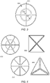
- Figure 4 shows alternative embodiments, representing circular membranes with different numbers of connecting rings and partially released cantilevers 301-302, and also membranes with alternative shaped geometries in particular a triangular 304, and a square 303 design.
- Figure 5(a) shows a full isometric view of the pMUT circular embodiment.
- Figure 5(b) shows the same isometric view of the embodiment, with an open cut section for better viewing and understanding of the pMUT structure and geometry.
- top electrode ( 104 ) aluminum (0.2 ⁇ m) / piezoelectric layer ( 102 ) - aluminum nitride (1 ⁇ m) / bottom electrode ( 106 ) - molybdenum (0.2 ⁇ m) / passive layer ( 101 ) - silicon (4 ⁇ m).
- Membrane diameter - 600 ⁇ m / gap ( 103 ) - 4 ⁇ m. Connecting rings width - 4 ⁇ m.
- the preferred pMUT embodiment also has advantages in terms of maximum displacement and acoustic performance in both transmitter and receiver mode, when compared to a fully clamped membrane.
- the mechanical nature of a cantilever beam allows it to displace much more than a constrained or fully clamped membrane structure.
- figure 7 shows the results of FEM simulation of the static displacement per unit volt of a standard fully clamped circular pMUT, and the proposed slotted pMUT with similar dimensions. This enhancement in displacement directly translates to augmented output pressure.
- figure 8 shows the results of FEM simulations of resonance frequency for pMUTs having various numbers of sliced cantilevers and ring connectors in the membrane for the following structure: top electrode ( 104 ) - aluminum (0.2 ⁇ m) / piezoelectric layer ( 102 ) - aluminum nitride (1 ⁇ m) / bottom electrode ( 106 ) - molybdenum (0.2 ⁇ m) / passive layer ( 101 ) - silicon (4 ⁇ m).
- the resonance frequency decreases with the number of slices and rings, and for this particular example, the frequency can be adjusted in a range of 23 kHz (189 to 212 kHz). of slices and rings, and for this particular example, the frequency can be adjusted in a range of 23 kHz (189 to 212 kHz).
Description
- The present disclosure generally relates to micromachined ultrasonic transducers (MUTs) and more particularly to a design for a piezoelectric micromachined ultrasonic transducer (PMUT) device and a method to fabricate such a device.
- The following art appears relevant to the present disclosure:
-
Publication Number Kind Code Issue Date Patentee US2012/0250909 A1 Oct. 4, 2012 Grosh - Micromachined ultrasonic transducers (MUTs) have been subject to extensive research for the last two decades. Piezoelectric micromachined ultrasonic transducers (pMUTs) are MUTs that use a piezoelectric layer for electro-mechanical transduction. A typical pMUT is a multilayer membrane structure that is excited into flexural vibration using piezoelectric actuation. The membrane structure is often formed by etching through a silicon wafer to remove the material beneath the membrane, thereby allowing it to vibrate. This etch forms a hollow tube beneath the backside of the membrane. Sound is emitted from the tube when the membrane vibrates, and the tube may be designed as an acoustic resonator to improve acoustic performance of the pMUT. These devices typically operate at the membrane's flexural resonance frequency, which is defined by selecting the correct materials, membrane size, thickness and/or in-plane stress. For multi-pMUT applications, good matching of the resonance frequencies of the individual pMUTs is required for proper operation. For this reason, it is important for pMUTs to be manufactured with closely-matched resonance frequencies. One important parameter causing frequency variation is the residual stress present in the layers composing the pMUT membrane, in particular in the piezoelectric layer. A typical pMUT structure consists of a membrane that is attached to the substrate at its boundary, a condition that is described as a clamped boundary condition. The resonant frequency of a membrane with a clamped boundary condition is very sensitive to in-plane residual stress. Several designs have been suggested to reduce stress sensitivity, such as released cantilevers and flexurallysuspended membranes, but they all show poor acoustic performance and or poor manufacturability (e.g. inefficient resonance modes, cracks created by stress concentrations, poor micro-fabrication yield)
- In
US 2012/0250909 Grosh describes an acoustic transducer wherein a membrane transducer is released from the substrate by separating the membrane into several identical tapered cantilevers, reducing the effect of stress on the mechanical behavior of the membrane. Grosh's approach works well for a non-resonant device, such as a conventional piezoelectric microphone. However, for a pMUT operated at resonance, small differences caused by fabrication variations can cause the cantilevers to have slightly different resonance frequencies, resulting in considerable negative impact on the acoustic performance of the device when operated at resonance. Specifically, when excited at a single frequency, mismatched cantilevers will oscillate with significantly different phase and amplitude, creating phase and amplitude errors in the ultrasound signal. In addition,EP 2 362 686 - A2 discloses a hearing aid with a piezoelectric soundtransducer having cantilevers that are mechanically coupled by one concentric ring , but not a piezoelectric micromachined ultrasonic transducer, pMUT, transducer with at least two concentric rings that couple the cantilevers.
- Accordingly, what is needed is a pMUT design with good acoustic performance that resonates at a single stable resonance mode, and with low sensitivity to stress. This invention describes such design.
- The present teachings relate to a piezoelectric micromachined ultrasonic transducer (PMUT) device in accordance with
claim 1. A method for fabricating a piezoelectric micromachined ultrasonic transducer (PMUT) device is defined inclaim 8. Advantageous features are described in the dependent claims. According to aspects of this disclosure a piezoelectric micromachined ultrasonic transducer (PMUT) device may include a clamped membrane in any symmetric shape (circular, squared, triangular, among others) that is partially released by "slicing" the membrane into cantilevers, which may include two or more tapered and/or identically-shaped cantilevers. The individual cantilevers are mechanically coupled so that they resonate together at the same frequency, thereby avoiding the multiple resonant frequencies that occur with individually-defined cantilevers having small dimension variations. When compared to a fully clamped membrane, this design shows the following advantages: (i) reduced stress sensitivity; (ii) increased transmit and receive acoustic sensitivity, coming from the fact that the released design enables larger displacement of the membrane; (iii) resonance frequency adjustment - the resonance frequency of the device can be easily adjusted by defining the number of slices that comprise the structure, as well as the number of connections between slices. This feature is extremely advantageous since the resonance frequency can be adjusted without changing the basic dimensions of the membrane, such as diameter and thickness. - The present disclosure may be better understood by reference to the following drawings which are for illustrative purposes only:
-
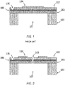
FIG.1 shows a cross section of a circular clamped transducer design known from prior art. -
FIG.2 is a cross section of a circular embodiment of the proposed partially released pMUT. -
FIG.3 is a top view of the proposed pMUT, showing a 4 slice design, with one connecting ring (highlighted). -
FIG.4 is a top view of different alternative embodiments with different shapes, comprising different number of partially released cantilevers: 4, 6 and 8. -
FIG.5(a) shows a full isometric view of the pMUT circular embodiment.FIG.5(b) shows the same isometric view of the embodiment, with an open cut section for better viewing and understanding of the pMUT structure and geometry. -
FIG.6 Comparison of the stress sensitivity of a fully clamped pMUT membrane, and the proposed pMUT design comprising different number of cantilever slices and connecting rings. -
FIG.7 shows a comparison of the static displacement in nm/V of a standard clamped pMUT membrane, and the proposed pMUT design comprising 4, 6 and 8 slices/cantilevers all with two connecting rings. -
FIG.8 Resonance frequencies for similar pMUT embodiments with different number of released cantilevers, and connecting rings. - Although the description herein contains many details, these should not be construed as limiting the scope of the invention but as merely providing illustrations of some of the presently preferred embodiments of this invention. It should be noted and understood that there can be improvements and modifications made of the present invention described in detail below without departing from the scope of the invention as set forth in the accompanying claims.
- Aspects of this disclosure include a micromachined ultrasonic transducer (MUT), in particular a piezoelectric micromachined ultrasonic transducer (pMUT) device comprising a circular membrane, sliced in identical tapered cantilevers anchored at the perimeter of the membrane. The cantilevers are mechanically coupled; in one embodiment the coupling may be accomplished using several concentric rings. It will be appreciated that the following embodiments are provided by way of example only, and that numerous variations and modifications are possible. For example, while circular embodiments are shown, the pMUT membrane may have many different shapes such as square, rectangular, hexagonal, octagonal, and so on. Furthermore, while pMUTs are shown in this description, other MUTs should also be considered, such as capacitive micromachined ultrasonic transducers (cMUTs) or optical acoustic transducers. Also, although this description is focused on pMUTs having a unimorph construction, consisting of a single piezoelectric layer on a passive layer, aspects of the disclosure are not limited thereby. For example, bimorph and multimorph pMUTs having multiple piezoelectric layers and various electrode patterns are possible, and should also be considered part of the present disclosure. All such variations that would be apparent to one of ordinary skill in the art are intended to fall within the scope of this disclosure. It will also be appreciated that the drawings are not necessarily to scale, with emphasis being instead on the distinguishing features of the bonded wafer pMUT device disclosed herein.
-
Figure 2 is a cross-section illustration of the proposed pMUT formed from multiple thin-film layers deposited onto thesubstrate 100.Substrate 100 may be silicon but alternative materials such as glass or polymer substrates may be used. In the unimorph pMUT construction illustrated here as one embodiment, apassive layer 101 is first deposited onto thesubstrate 100.Passive layer 101 may be composed of various materials such as silicon, silicon oxide, and/or silicon nitride, and the thickness of this layer is in the range of 0.5 microns to 30 microns for transducers with center frequency from 40 kHz to 20 MHz, and more specifically from 1 micron to 10 microns for transducers with center frequency from 40 kHz to 1 MHz. A conductive metalbottom electrode layer 106 is then deposited.Bottom electrode 106 can be patterned or not, and may be composed of various metals such as Mo, Pt, or Al, and the thickness of this layer is from 50 nm to 400 nm and more specifically from 100 nm to 300 nm.Piezoelectric layer 102 may be composed of various piezoelectric materials including AIN, PZT (lead zirconate titanate), ZnO, KNN (KxNa1-xNbO3) or PMN-PT (lead magnesium niobate - lead titanate). Polymer piezoelectric materials such as PVDF may be used aspiezoelectric layer 102 as well. The thickness of piezoelectric layer 122 is from 250 nm to 3000 nm, and more specifically from 500 nm to 1500 nm. A conductive topelectrode metal layer 104 is then deposited. Various metals may be used fortop electrode 104, including Al, Au, Cu, and Mo. The thickness oftop electrode 104 is from 50 nm to 3000 nm and more specifically from 100 nm to 1000 nm. Electrical contact to thebottom electrode metal 106 is formed by etching a via 105 through thepiezoelectric layer 102. The multilayer membrane is then etched to form identical tapered cantilevers anchored at the perimeter of the membrane. The cantilevers are mechanically coupled to ensure that they resonate at a common frequency. In one embodiment, this coupling is achieved by one or more concentric rings connecting the cantilevers. Thegap 103 should be smaller than (1 µm)/fo, where fo is the operational frequency in MHz, or more specifically smaller than (0.6 µm)/fo. Thegap 103, theconcentric ring connection 202, and partially released pMUT triangular cantilevers can be better understood from top viewfigure 3 . The number of cantilever slices can be defined to target a specific acoustic performance and resonance frequency. The final pMUT structure is formed by releasing the membrane from thesubstrate 100. In one embodiment, the release etch is performed by etching through the back of the wafer, forming anopening 107, e.g., a tube, through backside of thesubstrate 100. When a silicon substrate is employed, this etch may be conducted by deep reactive ion etching (DRIE). Alternative fabrication methods using frontside etching to release the membrane are also possible. The membrane diameter is in the range of 100 microns to 2000 microns for transducers operating at frequencies from 40 kHz to 10 MHz and more specifically the diameter is from 200 microns to 1500 microns for transducers operating at frequencies from 60 kHz to 600 kHz. The etch may be performed after thinning thesubstrate 100 by grinding or other means. The thickness of thesubstrate 100 may be determined such that theopening 107 possesses an acoustic resonance frequency that is matched to the center frequency of the PMUT. -
Figure 4 shows alternative embodiments, representing circular membranes with different numbers of connecting rings and partially released cantilevers 301-302, and also membranes with alternative shaped geometries in particular a triangular 304, and a square 303 design. -
Figure 5(a) shows a full isometric view of the pMUT circular embodiment.Figure 5(b) shows the same isometric view of the embodiment, with an open cut section for better viewing and understanding of the pMUT structure and geometry. - By partially etching the
gaps 103 to define the suspended cantilevers in the membrane, the stress sensitivity is largely reduced. The in-plane stress present in the pMUT structural layers is released due to the less constrained geometry of the released cantilevers. The stress release has an effect on the initial static deformation of the pMUT, which will deform up or downwards, depending on the average residual stress and residual stress gradients present in the layers. Finite element method (FEM) simulations were conducted to model the resonance frequency of several pMUT designs at varying levels of residual stress in the piezoelectric layer.Figure 6 compares resonance frequency as a function of residual stress for the standard clamped design, and three preferred pMUT embodiments with four, six and eight partially released cantilevers. For this example the following pMUT structure was considered: top electrode (104) - aluminum (0.2 µm) / piezoelectric layer (102) - aluminum nitride (1 µm) / bottom electrode (106) - molybdenum (0.2 µm) / passive layer (101) - silicon (4 µm). Membrane diameter - 600 µm / gap (103) - 4 µm. Connecting rings width - 4 µm. - The preferred pMUT embodiment also has advantages in terms of maximum displacement and acoustic performance in both transmitter and receiver mode, when compared to a fully clamped membrane. When driven at resonance, the mechanical nature of a cantilever beam allows it to displace much more than a constrained or fully clamped membrane structure. By way of example, and not of limitation,
figure 7 shows the results of FEM simulation of the static displacement per unit volt of a standard fully clamped circular pMUT, and the proposed slotted pMUT with similar dimensions. This enhancement in displacement directly translates to augmented output pressure. - The number of slices/cantilevers and the number of ring connectors that mechanically couple the cantilevers together can be used to adjust the resonance frequency of the structure without changing its basic dimensions such as the thickness of the layers and/or the diameter of the membrane. By way of example, and not of limitation,
figure 8 shows the results of FEM simulations of resonance frequency for pMUTs having various numbers of sliced cantilevers and ring connectors in the membrane for the following structure: top electrode (104) - aluminum (0.2 µm) / piezoelectric layer (102) - aluminum nitride (1 µm) / bottom electrode (106) - molybdenum (0.2 µm) / passive layer (101) - silicon (4 µm). Membrane diameter - 600 µm / gap (103) - 4 µm. Connecting rings width - 4 µm. As seen inFigure 8 , the resonance frequency decreases with the number of slices and rings, and for this particular example, the frequency can be adjusted in a range of 23 kHz (189 to 212 kHz). of slices and rings, and for this particular example, the frequency can be adjusted in a range of 23 kHz (189 to 212 kHz). - It should be noted and understood that there can be improvements and modifications made of the present invention described in detail above without departing from the scope of the invention as set forth in the accompanying claims.
Claims (12)
- A piezoelectric micromachined ultrasonic transducer, PMUT, device, comprising:a substrate (100) having an open cavity; anda membrane attached to the substrate over the opening, a portion of the membrane that overlies the open cavity being divided into a plurality of cantilevers (301-302) defined by a plurality of gaps (103) in the membrane, wherein the cantilevers (301-302) are anchored at the perimeter of the membrane and wherein the cantilevers (301-302) are mechanically coupled by two or more concentric rings so that the cantilevers (301-302) resonate at a common frequency.
- The device of claim 1, wherein the open cavity is fully open through the substrate (100) from a side of the substrate to which the membrane is attached to a side of the substrate opposite the side of the substrate to which the membrane is attached.
- The device of claim 1, wherein the cavity is partially open from a side of the substrate (100) to which the membrane is attached but not through to a side of the substrate opposite the side of the substrate to which the membrane is attached.
- The device of claim 1, wherein a shape of the membrane is a symmetrical shape.
- The device of claim 1, wherein the plurality of cantilevers includes:two or more cantilevers;three or more cantilevers;four or more cantilevers;six or more cantilevers;eight or more cantilevers;two or more identically-shaped cantilevers;two or more tapered cantilevers; ortwo or more identically-shaped tapered cantilevers.
- The device of claim 1, wherein the membrane includes multiple layers of material, including a passive layer (101) formed on the substrate, a conductive bottom electrode layer (106) formed on the passive layer, a piezoelectric layer (102) formed on the conductive bottom electrode layer, and a conductive top electrode layer (104) formed on the piezoelectric layer.
- The device of claim 1, wherein the cantilevers are mechanically coupled by three or more concentric rings.
- A method for fabricating a piezoelectric micromachined ultrasonic transducer, PMUT, device, comprising:forming a membrane attached to a substrate (100);dividing a portion of the membrane into a plurality of cantilevers (301-302) that are defined by a plurality of gaps (103) in the membrane, wherein the cantilevers (301-302) are anchored at the perimeter of the membrane and wherein the cantilevers (301-302) are mechanically coupled by two or more concentric rings; andforming an opening through a portion of the substrate underlying the plurality of cantilevers (301-302) to release the cantilevers (301-302), wherein the cantilevers (301-302) are mechanically coupled so that the cantilevers (301-302) resonate at a common frequency.
- The method of claim 8, wherein a shape of the membrane is a symmetrical shape.
- The method of claim 8, wherein the plurality of cantilevers includes:two or more cantilevers;three or more cantilevers;four or more cantilevers;six or more cantilevers;eight or more cantilevers;two or more identically-shaped cantilevers;two or more tapered cantilevers; ortwo or more identically-shaped tapered cantilevers.
- The method of claim 9, wherein forming the membrane includes forming multiple layers of material including a passive layer (101) on the substrate, a conductive bottom electrode layer (106) on the passive layer, a conductive bottom electrode layer on the passive layer, a piezoelectric layer (102) on the conductive bottom electrode layer, and a conductive top electrode layer (104) on the piezoelectric layer.
- The method of claim 8, wherein dividing a portion of the membrane into a plurality of cantilevers that are defined by a plurality of gaps (103) in the membrane includes dividing said portion of the membrane into a plurality of identically-shaped tapered cantilevers, and wherein the plurality of identically-shaped tapered cantilevers are coupled by the two or more concentric rings or three or more concentric rings.
Applications Claiming Priority (2)
| Application Number | Priority Date | Filing Date | Title |
|---|---|---|---|
| US201462058909P | 2014-10-02 | 2014-10-02 | |
| PCT/US2015/053605 WO2016054447A1 (en) | 2014-10-02 | 2015-10-01 | Micromachined ultrasonic transducers with a slotted membrane structure |
Publications (3)
| Publication Number | Publication Date |
|---|---|
| EP3201122A1 EP3201122A1 (en) | 2017-08-09 |
| EP3201122A4 EP3201122A4 (en) | 2018-05-30 |
| EP3201122B1 true EP3201122B1 (en) | 2022-12-28 |
Family
ID=55631565
Family Applications (1)
| Application Number | Title | Priority Date | Filing Date |
|---|---|---|---|
| EP15846584.9A Active EP3201122B1 (en) | 2014-10-02 | 2015-10-01 | Micromachined ultrasonic transducers with a slotted membrane structure |
Country Status (3)
| Country | Link |
|---|---|
| US (1) | US10293377B2 (en) |
| EP (1) | EP3201122B1 (en) |
| WO (1) | WO2016054447A1 (en) |
Families Citing this family (41)
| Publication number | Priority date | Publication date | Assignee | Title |
|---|---|---|---|---|
| US20200322731A1 (en) * | 2013-10-17 | 2020-10-08 | Merry Electronics(Shenzhen) Co., Ltd. | Acoustic transducer |
| EP3201122B1 (en) | 2014-10-02 | 2022-12-28 | InvenSense, Inc. | Micromachined ultrasonic transducers with a slotted membrane structure |
| WO2016054448A1 (en) | 2014-10-02 | 2016-04-07 | Chirp Microsystems | Piezoelectric micromachined ultrasonic transducers having differential transmit and receive circuitry |
| WO2016106153A1 (en) * | 2014-12-21 | 2016-06-30 | Chirp Microsystems, Inc. | Piezoelectric micromachined ultrasonic transducers with low stress sensitivity and methods of fabrication |
| US11229927B2 (en) | 2015-10-21 | 2022-01-25 | Agency For Science, Technology And Research | Ultrasound transducer and method of forming ihe same |
| ITUB20155716A1 (en) | 2015-11-19 | 2017-05-19 | St Microelectronics Srl | MICRO-ELECTRO-MECHANICAL DEVICE EQUIPPED WITH TWO CAVITIES AND RELATIVE PROCESS OF MANUFACTURE |
| US10618079B2 (en) * | 2016-02-29 | 2020-04-14 | Qualcomm Incorporated | Piezoelectric micromechanical ultrasonic transducers and transducer arrays |
| EP3472829B1 (en) | 2016-06-17 | 2023-08-16 | InvenSense, Inc. | Piezoelectric micromachined ultrasonic transducers having stress relief features |
| WO2018076042A1 (en) * | 2016-10-31 | 2018-05-03 | Thales Australia Limited | Acoustic transducer |
| US11039814B2 (en) | 2016-12-04 | 2021-06-22 | Exo Imaging, Inc. | Imaging devices having piezoelectric transducers |
| CN110546776B (en) * | 2017-04-17 | 2023-04-18 | 锐迪科微电子(上海)有限公司 | MEMS piezoelectric transducer for optimizing capacitance shape |
| KR101949593B1 (en) * | 2017-05-30 | 2019-02-18 | 서울대학교산학협력단 | Mems device |
| KR101949594B1 (en) * | 2017-05-30 | 2019-04-29 | 서울대학교산학협력단 | Mems transducer package and mems device inlcuding the same |
| US10656007B2 (en) | 2018-04-11 | 2020-05-19 | Exo Imaging Inc. | Asymmetrical ultrasound transducer array |
| US10648852B2 (en) | 2018-04-11 | 2020-05-12 | Exo Imaging Inc. | Imaging devices having piezoelectric transceivers |
| TW201946700A (en) * | 2018-05-03 | 2019-12-16 | 美商蝴蝶網路公司 | Ultrasound devices |
| TWI684367B (en) * | 2018-09-14 | 2020-02-01 | 美律實業股份有限公司 | Speaker and microelectromechanical actuator thereof |
| JP6750765B1 (en) * | 2018-09-21 | 2020-09-02 | 株式会社村田製作所 | Piezoelectric device |
| US11865581B2 (en) | 2018-11-21 | 2024-01-09 | Stmicroelectronics S.R.L. | Ultrasonic MEMS acoustic transducer with reduced stress sensitivity and manufacturing process thereof |
| CN109587613B (en) * | 2018-12-31 | 2020-11-10 | 瑞声声学科技(深圳)有限公司 | Piezoelectric microphone |
| IT201900005808A1 (en) | 2019-04-15 | 2020-10-15 | St Microelectronics Srl | MICROPUMP MEMS DEVICE FOR HANDLING OR EJECTION OF A FLUID, IN PARTICULAR MICROSOFT OR FLOWMETER |
| CN110052391B (en) * | 2019-05-28 | 2023-06-16 | 浙江大学 | Micromechanical piezoelectric ultrasonic transducer coupled by double resonance modes |
| US11418887B2 (en) * | 2019-08-28 | 2022-08-16 | Taiwan Semiconductor Manufacturing Company Ltd. | MEMS device with enhanced membrane structure and method of forming the same |
| AU2020344610A1 (en) * | 2019-09-12 | 2022-04-07 | Exo Imaging, Inc. | Increased MUT coupling efficiency and bandwidth via edge groove, virtual pivots, and free boundaries |
| US11819361B2 (en) * | 2019-12-13 | 2023-11-21 | Invensense, Inc. | Split electrode design for a transducer |
| CN114830520A (en) | 2019-12-17 | 2022-07-29 | 株式会社村田制作所 | Energy converter |
| US11057716B1 (en) * | 2019-12-27 | 2021-07-06 | xMEMS Labs, Inc. | Sound producing device |
| US11252511B2 (en) * | 2019-12-27 | 2022-02-15 | xMEMS Labs, Inc. | Package structure and methods of manufacturing sound producing chip, forming package structure and forming sound producing apparatus |
| US11395073B2 (en) | 2020-04-18 | 2022-07-19 | xMEMS Labs, Inc. | Sound producing package structure and method for packaging sound producing package structure |
| US20230347382A1 (en) * | 2020-04-13 | 2023-11-02 | Stelect Pty. Ltd | Ultrasound transducers |
| EP4153428A4 (en) * | 2020-05-22 | 2023-12-20 | Magic Leap, Inc. | Method and system for scanning mems cantilevers |
| US11884535B2 (en) | 2020-07-11 | 2024-01-30 | xMEMS Labs, Inc. | Device, package structure and manufacturing method of device |
| US11323797B2 (en) * | 2020-07-11 | 2022-05-03 | xMEMS Labs, Inc. | Acoustic transducer, wearable sound device and manufacturing method of acoustic transducer |
| US11399228B2 (en) | 2020-07-11 | 2022-07-26 | xMEMS Labs, Inc. | Acoustic transducer, wearable sound device and manufacturing method of acoustic transducer |
| CN116325803A (en) * | 2020-09-07 | 2023-06-23 | 株式会社村田制作所 | Transducer |
| IT202000024469A1 (en) * | 2020-10-16 | 2022-04-16 | St Microelectronics Srl | MICROMACHINING PIEZOELECTRIC ULTRASONIC TRANSDUCER |
| US11819881B2 (en) | 2021-03-31 | 2023-11-21 | Exo Imaging, Inc. | Imaging devices having piezoelectric transceivers with harmonic characteristics |
| US11951512B2 (en) | 2021-03-31 | 2024-04-09 | Exo Imaging, Inc. | Imaging devices having piezoelectric transceivers with harmonic characteristics |
| CN113042350A (en) * | 2021-04-20 | 2021-06-29 | 广州蜂鸟传感科技有限公司 | Piezoelectric micro-mechanical transducer |
| US20230270011A1 (en) * | 2022-02-24 | 2023-08-24 | Qualcomm Technologies, Inc. | Piezoelectric micromachined ultrasonic transducer (pmut) design |
| WO2024070112A1 (en) * | 2022-09-30 | 2024-04-04 | 太陽誘電株式会社 | Ultrasonic transducer |
Family Cites Families (19)
| Publication number | Priority date | Publication date | Assignee | Title |
|---|---|---|---|---|
| US4398116A (en) | 1981-04-30 | 1983-08-09 | Siemens Gammasonics, Inc. | Transducer for electronic focal scanning in an ultrasound imaging device |
| JPS59144997U (en) * | 1983-03-18 | 1984-09-27 | 三洋電機株式会社 | piezoelectric sounding body |
| JPS61150499A (en) * | 1984-12-24 | 1986-07-09 | Sawafuji Dainameka Kk | Separate type piezoelectric diaphragm |
| US6535612B1 (en) * | 1998-12-07 | 2003-03-18 | American Technology Corporation | Electroacoustic transducer with diaphragm securing structure and method |
| DE10002567C1 (en) * | 2000-01-21 | 2001-09-27 | Siemens Audiologische Technik | Miniature electric-acoustic transducer |
| US7253488B2 (en) * | 2002-04-23 | 2007-08-07 | Sharp Laboratories Of America, Inc. | Piezo-TFT cantilever MEMS |
| US20050215907A1 (en) * | 2002-07-18 | 2005-09-29 | Minoru Toda | Ultrasonic transducer for electronic devices |
| JP3974114B2 (en) * | 2004-01-20 | 2007-09-12 | 株式会社東芝 | Diaphragm integrated substrate, acoustoelectric transducer, acoustoelectric conversion system, and method for manufacturing diaphragm integrated substrate |
| JP4622574B2 (en) * | 2005-02-21 | 2011-02-02 | 株式会社デンソー | Ultrasonic element |
| US7305883B2 (en) * | 2005-10-05 | 2007-12-11 | The Board Of Trustees Of The Leland Stanford Junior University | Chemical micromachined microsensors |
| JP5491080B2 (en) * | 2009-06-18 | 2014-05-14 | 国立大学法人 東京大学 | microphone |
| DE102010009453A1 (en) * | 2010-02-26 | 2011-09-01 | Fraunhofer-Gesellschaft zur Förderung der angewandten Forschung e.V. | Sound transducer for insertion in an ear |
| CA2819615A1 (en) * | 2010-12-03 | 2012-06-07 | Research Triangle Institute | Method for forming an ultrasonic transducer, and associated apparatus |
| JP4924853B1 (en) * | 2011-02-23 | 2012-04-25 | オムロン株式会社 | Acoustic sensor and microphone |
| WO2013002847A1 (en) | 2011-03-31 | 2013-01-03 | Bakr-Calling, Inc. | Acoustic transducer with gap-controlling geometry and method of manufacturing an acoustic transducer |
| US8667846B2 (en) * | 2011-04-19 | 2014-03-11 | Eastman Kodak Company | Method of operating an ultrasonic transmitter and receiver |
| WO2015131083A1 (en) * | 2014-02-28 | 2015-09-03 | The Regents Of The University Of California | Variable thickness diaphragm for a wideband robust piezoelectric micromachined ultrasonic transducer (pmut) |
| WO2016022187A2 (en) | 2014-05-12 | 2016-02-11 | Chirp Microsystems | Time of flight range finding with an adaptive transmit pulse and adaptive receiver processing |
| EP3201122B1 (en) | 2014-10-02 | 2022-12-28 | InvenSense, Inc. | Micromachined ultrasonic transducers with a slotted membrane structure |
-
2015
- 2015-10-01 EP EP15846584.9A patent/EP3201122B1/en active Active
- 2015-10-01 WO PCT/US2015/053605 patent/WO2016054447A1/en active Application Filing
-
2016
- 2016-04-28 US US15/141,746 patent/US10293377B2/en active Active
Also Published As
| Publication number | Publication date |
|---|---|
| EP3201122A1 (en) | 2017-08-09 |
| EP3201122A4 (en) | 2018-05-30 |
| US10293377B2 (en) | 2019-05-21 |
| US20170021391A1 (en) | 2017-01-26 |
| WO2016054447A1 (en) | 2016-04-07 |
Similar Documents
| Publication | Publication Date | Title |
|---|---|---|
| EP3201122B1 (en) | Micromachined ultrasonic transducers with a slotted membrane structure | |
| US11711067B2 (en) | Micromachined ultrasound transducer using multiple piezoelectric materials | |
| US20240049602A1 (en) | Piezoelectric Micromachined Ultrasonic Transducer With A Patterned Membrane Structure | |
| EP3233311B1 (en) | Piezoelectric micromachined ultrasonic transducers with low stress sensitivity and methods of fabrication | |
| US10576500B2 (en) | Piezoelectric micro-machined ultrasonic transducer (PMUT) and method for manufacturing the PMUT | |
| US7770279B2 (en) | Electrostatic membranes for sensors, ultrasonic transducers incorporating such membranes, and manufacturing methods therefor | |
| US11292030B2 (en) | Piezoelectric micromachined ultrasonic transducers having stress relief features | |
| US8329053B2 (en) | Micromachined transducers and method of fabrication | |
| EP3036779B1 (en) | Multi-layered thin film piezoelectric devices & methods of making the same | |
| EP3530358B1 (en) | Improved micromachined ultrasonic transducer (mut), method for manufacturing the mut, and method for designing the mut | |
| Horsley et al. | Piezoelectric micromachined ultrasonic transducers for human-machine interfaces and biometric sensing | |
| Luo et al. | High-pressure output 40 kHz air-coupled piezoelectric micromachined ultrasonic transducers | |
| EP3317026B1 (en) | Ultrasound system and ultrasonic pulse transmission method | |
| Chao et al. | Piezoelectric micromachined ultrasonic transducers based on P (VDF-TrFE) copolymer thin films | |
| Ren et al. | Micromachined piezoelectric acoustic device | |
| CN113896165A (en) | Piezoelectric micromechanical ultrasonic transducer and manufacturing method thereof | |
| CN114105082A (en) | Piezoelectric micromechanical ultrasonic transducer and manufacturing method thereof | |
| CN116809363A (en) | Piezoelectric MEMS ultrasonic transducer imitating Langmuir vibrator and preparation method thereof | |
| CN115945375A (en) | Piston mode capacitance piezoelectric composite miniature ultrasonic transducer and preparation method thereof |
Legal Events
| Date | Code | Title | Description |
|---|---|---|---|
| STAA | Information on the status of an ep patent application or granted ep patent |
Free format text: STATUS: THE INTERNATIONAL PUBLICATION HAS BEEN MADE |
|
| PUAI | Public reference made under article 153(3) epc to a published international application that has entered the european phase |
Free format text: ORIGINAL CODE: 0009012 |
|
| STAA | Information on the status of an ep patent application or granted ep patent |
Free format text: STATUS: REQUEST FOR EXAMINATION WAS MADE |
|
| 17P | Request for examination filed |
Effective date: 20170405 |
|
| AK | Designated contracting states |
Kind code of ref document: A1 Designated state(s): AL AT BE BG CH CY CZ DE DK EE ES FI FR GB GR HR HU IE IS IT LI LT LU LV MC MK MT NL NO PL PT RO RS SE SI SK SM TR |
|
| AX | Request for extension of the european patent |
Extension state: BA ME |
|
| DAV | Request for validation of the european patent (deleted) | ||
| DAX | Request for extension of the european patent (deleted) | ||
| A4 | Supplementary search report drawn up and despatched |
Effective date: 20180504 |
|
| RIC1 | Information provided on ipc code assigned before grant |
Ipc: G01N 29/24 20060101ALI20180426BHEP Ipc: B06B 1/06 20060101ALI20180426BHEP Ipc: G10K 13/00 20060101ALI20180426BHEP Ipc: B81B 3/00 20060101AFI20180426BHEP Ipc: H01L 41/113 20060101ALI20180426BHEP Ipc: H01L 41/04 20060101ALI20180426BHEP Ipc: G10K 9/125 20060101ALI20180426BHEP |
|
| STAA | Information on the status of an ep patent application or granted ep patent |
Free format text: STATUS: EXAMINATION IS IN PROGRESS |
|
| 17Q | First examination report despatched |
Effective date: 20211202 |
|
| GRAP | Despatch of communication of intention to grant a patent |
Free format text: ORIGINAL CODE: EPIDOSNIGR1 |
|
| STAA | Information on the status of an ep patent application or granted ep patent |
Free format text: STATUS: GRANT OF PATENT IS INTENDED |
|
| INTG | Intention to grant announced |
Effective date: 20220826 |
|
| RAP1 | Party data changed (applicant data changed or rights of an application transferred) |
Owner name: INVENSENSE, INC. |
|
| GRAS | Grant fee paid |
Free format text: ORIGINAL CODE: EPIDOSNIGR3 |
|
| GRAA | (expected) grant |
Free format text: ORIGINAL CODE: 0009210 |
|
| STAA | Information on the status of an ep patent application or granted ep patent |
Free format text: STATUS: THE PATENT HAS BEEN GRANTED |
|
| AK | Designated contracting states |
Kind code of ref document: B1 Designated state(s): AL AT BE BG CH CY CZ DE DK EE ES FI FR GB GR HR HU IE IS IT LI LT LU LV MC MK MT NL NO PL PT RO RS SE SI SK SM TR |
|
| REG | Reference to a national code |
Ref country code: GB Ref legal event code: FG4D |
|
| REG | Reference to a national code |
Ref country code: CH Ref legal event code: EP |
|
| REG | Reference to a national code |
Ref country code: DE Ref legal event code: R096 Ref document number: 602015082114 Country of ref document: DE |
|
| REG | Reference to a national code |
Ref country code: AT Ref legal event code: REF Ref document number: 1540371 Country of ref document: AT Kind code of ref document: T Effective date: 20230115 |
|
| REG | Reference to a national code |
Ref country code: IE Ref legal event code: FG4D |
|
| REG | Reference to a national code |
Ref country code: LT Ref legal event code: MG9D |
|
| PG25 | Lapsed in a contracting state [announced via postgrant information from national office to epo] |
Ref country code: SE Free format text: LAPSE BECAUSE OF FAILURE TO SUBMIT A TRANSLATION OF THE DESCRIPTION OR TO PAY THE FEE WITHIN THE PRESCRIBED TIME-LIMIT Effective date: 20221228 Ref country code: NO Free format text: LAPSE BECAUSE OF FAILURE TO SUBMIT A TRANSLATION OF THE DESCRIPTION OR TO PAY THE FEE WITHIN THE PRESCRIBED TIME-LIMIT Effective date: 20230328 Ref country code: LT Free format text: LAPSE BECAUSE OF FAILURE TO SUBMIT A TRANSLATION OF THE DESCRIPTION OR TO PAY THE FEE WITHIN THE PRESCRIBED TIME-LIMIT Effective date: 20221228 Ref country code: FI Free format text: LAPSE BECAUSE OF FAILURE TO SUBMIT A TRANSLATION OF THE DESCRIPTION OR TO PAY THE FEE WITHIN THE PRESCRIBED TIME-LIMIT Effective date: 20221228 |
|
| REG | Reference to a national code |
Ref country code: NL Ref legal event code: MP Effective date: 20221228 |
|
| REG | Reference to a national code |
Ref country code: AT Ref legal event code: MK05 Ref document number: 1540371 Country of ref document: AT Kind code of ref document: T Effective date: 20221228 |
|
| PG25 | Lapsed in a contracting state [announced via postgrant information from national office to epo] |
Ref country code: RS Free format text: LAPSE BECAUSE OF FAILURE TO SUBMIT A TRANSLATION OF THE DESCRIPTION OR TO PAY THE FEE WITHIN THE PRESCRIBED TIME-LIMIT Effective date: 20221228 Ref country code: LV Free format text: LAPSE BECAUSE OF FAILURE TO SUBMIT A TRANSLATION OF THE DESCRIPTION OR TO PAY THE FEE WITHIN THE PRESCRIBED TIME-LIMIT Effective date: 20221228 Ref country code: HR Free format text: LAPSE BECAUSE OF FAILURE TO SUBMIT A TRANSLATION OF THE DESCRIPTION OR TO PAY THE FEE WITHIN THE PRESCRIBED TIME-LIMIT Effective date: 20221228 Ref country code: GR Free format text: LAPSE BECAUSE OF FAILURE TO SUBMIT A TRANSLATION OF THE DESCRIPTION OR TO PAY THE FEE WITHIN THE PRESCRIBED TIME-LIMIT Effective date: 20230329 |
|
| P01 | Opt-out of the competence of the unified patent court (upc) registered |
Effective date: 20230524 |
|
| PG25 | Lapsed in a contracting state [announced via postgrant information from national office to epo] |
Ref country code: NL Free format text: LAPSE BECAUSE OF FAILURE TO SUBMIT A TRANSLATION OF THE DESCRIPTION OR TO PAY THE FEE WITHIN THE PRESCRIBED TIME-LIMIT Effective date: 20221228 |
|
| PG25 | Lapsed in a contracting state [announced via postgrant information from national office to epo] |
Ref country code: SM Free format text: LAPSE BECAUSE OF FAILURE TO SUBMIT A TRANSLATION OF THE DESCRIPTION OR TO PAY THE FEE WITHIN THE PRESCRIBED TIME-LIMIT Effective date: 20221228 Ref country code: RO Free format text: LAPSE BECAUSE OF FAILURE TO SUBMIT A TRANSLATION OF THE DESCRIPTION OR TO PAY THE FEE WITHIN THE PRESCRIBED TIME-LIMIT Effective date: 20221228 Ref country code: PT Free format text: LAPSE BECAUSE OF FAILURE TO SUBMIT A TRANSLATION OF THE DESCRIPTION OR TO PAY THE FEE WITHIN THE PRESCRIBED TIME-LIMIT Effective date: 20230428 Ref country code: ES Free format text: LAPSE BECAUSE OF FAILURE TO SUBMIT A TRANSLATION OF THE DESCRIPTION OR TO PAY THE FEE WITHIN THE PRESCRIBED TIME-LIMIT Effective date: 20221228 Ref country code: EE Free format text: LAPSE BECAUSE OF FAILURE TO SUBMIT A TRANSLATION OF THE DESCRIPTION OR TO PAY THE FEE WITHIN THE PRESCRIBED TIME-LIMIT Effective date: 20221228 Ref country code: CZ Free format text: LAPSE BECAUSE OF FAILURE TO SUBMIT A TRANSLATION OF THE DESCRIPTION OR TO PAY THE FEE WITHIN THE PRESCRIBED TIME-LIMIT Effective date: 20221228 Ref country code: AT Free format text: LAPSE BECAUSE OF FAILURE TO SUBMIT A TRANSLATION OF THE DESCRIPTION OR TO PAY THE FEE WITHIN THE PRESCRIBED TIME-LIMIT Effective date: 20221228 |
|
| PG25 | Lapsed in a contracting state [announced via postgrant information from national office to epo] |
Ref country code: SK Free format text: LAPSE BECAUSE OF FAILURE TO SUBMIT A TRANSLATION OF THE DESCRIPTION OR TO PAY THE FEE WITHIN THE PRESCRIBED TIME-LIMIT Effective date: 20221228 Ref country code: PL Free format text: LAPSE BECAUSE OF FAILURE TO SUBMIT A TRANSLATION OF THE DESCRIPTION OR TO PAY THE FEE WITHIN THE PRESCRIBED TIME-LIMIT Effective date: 20221228 Ref country code: IS Free format text: LAPSE BECAUSE OF FAILURE TO SUBMIT A TRANSLATION OF THE DESCRIPTION OR TO PAY THE FEE WITHIN THE PRESCRIBED TIME-LIMIT Effective date: 20230428 Ref country code: AL Free format text: LAPSE BECAUSE OF FAILURE TO SUBMIT A TRANSLATION OF THE DESCRIPTION OR TO PAY THE FEE WITHIN THE PRESCRIBED TIME-LIMIT Effective date: 20221228 |
|
| REG | Reference to a national code |
Ref country code: DE Ref legal event code: R097 Ref document number: 602015082114 Country of ref document: DE |
|
| PG25 | Lapsed in a contracting state [announced via postgrant information from national office to epo] |
Ref country code: DK Free format text: LAPSE BECAUSE OF FAILURE TO SUBMIT A TRANSLATION OF THE DESCRIPTION OR TO PAY THE FEE WITHIN THE PRESCRIBED TIME-LIMIT Effective date: 20221228 |
|
| PLBE | No opposition filed within time limit |
Free format text: ORIGINAL CODE: 0009261 |
|
| STAA | Information on the status of an ep patent application or granted ep patent |
Free format text: STATUS: NO OPPOSITION FILED WITHIN TIME LIMIT |
|
| 26N | No opposition filed |
Effective date: 20230929 |
|
| PG25 | Lapsed in a contracting state [announced via postgrant information from national office to epo] |
Ref country code: SI Free format text: LAPSE BECAUSE OF FAILURE TO SUBMIT A TRANSLATION OF THE DESCRIPTION OR TO PAY THE FEE WITHIN THE PRESCRIBED TIME-LIMIT Effective date: 20221228 |
|
| PGFP | Annual fee paid to national office [announced via postgrant information from national office to epo] |
Ref country code: DE Payment date: 20230830 Year of fee payment: 9 |