EP3144919B1 - Device and method for start assistance for a motor vehicle - Google Patents
Device and method for start assistance for a motor vehicle Download PDFInfo
- Publication number
- EP3144919B1 EP3144919B1 EP15465540.1A EP15465540A EP3144919B1 EP 3144919 B1 EP3144919 B1 EP 3144919B1 EP 15465540 A EP15465540 A EP 15465540A EP 3144919 B1 EP3144919 B1 EP 3144919B1
- Authority
- EP
- European Patent Office
- Prior art keywords
- motor vehicle
- starting
- pedestrians
- environment
- pedestrian
- Prior art date
- Legal status (The legal status is an assumption and is not a legal conclusion. Google has not performed a legal analysis and makes no representation as to the accuracy of the status listed.)
- Active
Links
- 238000000034 method Methods 0.000 title claims description 24
- 238000001514 detection method Methods 0.000 claims description 18
- 238000003384 imaging method Methods 0.000 claims description 13
- 230000003287 optical effect Effects 0.000 claims description 7
- 238000002604 ultrasonography Methods 0.000 claims description 5
- 241000283070 Equus zebra Species 0.000 description 4
- 238000001454 recorded image Methods 0.000 description 4
- 238000011161 development Methods 0.000 description 3
- 230000018109 developmental process Effects 0.000 description 3
- 230000000295 complement effect Effects 0.000 description 2
- 230000005855 radiation Effects 0.000 description 2
- 239000004065 semiconductor Substances 0.000 description 2
- 230000003466 anti-cipated effect Effects 0.000 description 1
- 238000013459 approach Methods 0.000 description 1
- 230000001419 dependent effect Effects 0.000 description 1
- 229910044991 metal oxide Inorganic materials 0.000 description 1
- 150000004706 metal oxides Chemical class 0.000 description 1
- 238000005096 rolling process Methods 0.000 description 1
Images


Classifications
-
- G—PHYSICS
- G08—SIGNALLING
- G08G—TRAFFIC CONTROL SYSTEMS
- G08G1/00—Traffic control systems for road vehicles
- G08G1/16—Anti-collision systems
- G08G1/166—Anti-collision systems for active traffic, e.g. moving vehicles, pedestrians, bikes
-
- B—PERFORMING OPERATIONS; TRANSPORTING
- B60—VEHICLES IN GENERAL
- B60T—VEHICLE BRAKE CONTROL SYSTEMS OR PARTS THEREOF; BRAKE CONTROL SYSTEMS OR PARTS THEREOF, IN GENERAL; ARRANGEMENT OF BRAKING ELEMENTS ON VEHICLES IN GENERAL; PORTABLE DEVICES FOR PREVENTING UNWANTED MOVEMENT OF VEHICLES; VEHICLE MODIFICATIONS TO FACILITATE COOLING OF BRAKES
- B60T7/00—Brake-action initiating means
- B60T7/12—Brake-action initiating means for automatic initiation; for initiation not subject to will of driver or passenger
- B60T7/22—Brake-action initiating means for automatic initiation; for initiation not subject to will of driver or passenger initiated by contact of vehicle, e.g. bumper, with an external object, e.g. another vehicle, or by means of contactless obstacle detectors mounted on the vehicle
-
- B—PERFORMING OPERATIONS; TRANSPORTING
- B60—VEHICLES IN GENERAL
- B60W—CONJOINT CONTROL OF VEHICLE SUB-UNITS OF DIFFERENT TYPE OR DIFFERENT FUNCTION; CONTROL SYSTEMS SPECIALLY ADAPTED FOR HYBRID VEHICLES; ROAD VEHICLE DRIVE CONTROL SYSTEMS FOR PURPOSES NOT RELATED TO THE CONTROL OF A PARTICULAR SUB-UNIT
- B60W30/00—Purposes of road vehicle drive control systems not related to the control of a particular sub-unit, e.g. of systems using conjoint control of vehicle sub-units
- B60W30/18—Propelling the vehicle
- B60W30/18009—Propelling the vehicle related to particular drive situations
- B60W30/18027—Drive off, accelerating from standstill
-
- B—PERFORMING OPERATIONS; TRANSPORTING
- B60—VEHICLES IN GENERAL
- B60W—CONJOINT CONTROL OF VEHICLE SUB-UNITS OF DIFFERENT TYPE OR DIFFERENT FUNCTION; CONTROL SYSTEMS SPECIALLY ADAPTED FOR HYBRID VEHICLES; ROAD VEHICLE DRIVE CONTROL SYSTEMS FOR PURPOSES NOT RELATED TO THE CONTROL OF A PARTICULAR SUB-UNIT
- B60W40/00—Estimation or calculation of non-directly measurable driving parameters for road vehicle drive control systems not related to the control of a particular sub unit, e.g. by using mathematical models
- B60W40/02—Estimation or calculation of non-directly measurable driving parameters for road vehicle drive control systems not related to the control of a particular sub unit, e.g. by using mathematical models related to ambient conditions
-
- G—PHYSICS
- G06—COMPUTING; CALCULATING OR COUNTING
- G06V—IMAGE OR VIDEO RECOGNITION OR UNDERSTANDING
- G06V20/00—Scenes; Scene-specific elements
- G06V20/50—Context or environment of the image
- G06V20/56—Context or environment of the image exterior to a vehicle by using sensors mounted on the vehicle
- G06V20/58—Recognition of moving objects or obstacles, e.g. vehicles or pedestrians; Recognition of traffic objects, e.g. traffic signs, traffic lights or roads
-
- G—PHYSICS
- G08—SIGNALLING
- G08G—TRAFFIC CONTROL SYSTEMS
- G08G1/00—Traffic control systems for road vehicles
- G08G1/14—Traffic control systems for road vehicles indicating individual free spaces in parking areas
- G08G1/141—Traffic control systems for road vehicles indicating individual free spaces in parking areas with means giving the indication of available parking spaces
- G08G1/143—Traffic control systems for road vehicles indicating individual free spaces in parking areas with means giving the indication of available parking spaces inside the vehicles
-
- B—PERFORMING OPERATIONS; TRANSPORTING
- B60—VEHICLES IN GENERAL
- B60T—VEHICLE BRAKE CONTROL SYSTEMS OR PARTS THEREOF; BRAKE CONTROL SYSTEMS OR PARTS THEREOF, IN GENERAL; ARRANGEMENT OF BRAKING ELEMENTS ON VEHICLES IN GENERAL; PORTABLE DEVICES FOR PREVENTING UNWANTED MOVEMENT OF VEHICLES; VEHICLE MODIFICATIONS TO FACILITATE COOLING OF BRAKES
- B60T2210/00—Detection or estimation of road or environment conditions; Detection or estimation of road shapes
- B60T2210/30—Environment conditions or position therewithin
- B60T2210/32—Vehicle surroundings
-
- B—PERFORMING OPERATIONS; TRANSPORTING
- B60—VEHICLES IN GENERAL
- B60W—CONJOINT CONTROL OF VEHICLE SUB-UNITS OF DIFFERENT TYPE OR DIFFERENT FUNCTION; CONTROL SYSTEMS SPECIALLY ADAPTED FOR HYBRID VEHICLES; ROAD VEHICLE DRIVE CONTROL SYSTEMS FOR PURPOSES NOT RELATED TO THE CONTROL OF A PARTICULAR SUB-UNIT
- B60W2554/00—Input parameters relating to objects
-
- B—PERFORMING OPERATIONS; TRANSPORTING
- B60—VEHICLES IN GENERAL
- B60W—CONJOINT CONTROL OF VEHICLE SUB-UNITS OF DIFFERENT TYPE OR DIFFERENT FUNCTION; CONTROL SYSTEMS SPECIALLY ADAPTED FOR HYBRID VEHICLES; ROAD VEHICLE DRIVE CONTROL SYSTEMS FOR PURPOSES NOT RELATED TO THE CONTROL OF A PARTICULAR SUB-UNIT
- B60W2710/00—Output or target parameters relating to a particular sub-units
- B60W2710/18—Braking system
Definitions
- the present invention relates to start-up assistants and driver assistance systems for motor vehicles, which assist the driver when starting.
- the present invention relates to a device and a method for starting assistance for a motor vehicle.
- Starting assistants for motor vehicles can be connected to an automatic stop function of the motor vehicle. Thanks to the automatic stop function and the start-up assistant, the service or parking brake system is automatically activated when the vehicle is at a standstill to prevent it from rolling away unintentionally.
- the state of the art is the published patent application EP 1703482 A1 known.
- the document discloses a device for starting assistance of a vehicle with an environment detection sensor for detecting a vehicle environment for the application that the vehicle follows a vehicle in front.
- an environment detection sensor for detecting a vehicle environment for the application that the vehicle follows a vehicle in front.
- an image of the surroundings in front of the vehicle is recorded. If the vehicle traveling in front approaches, an image of the surroundings in front of the vehicle is again acquired. Both images agree matches, there is an automatic restart. If the two images do not match, it is concluded that an object has moved into the space in front of the vehicle and an automatic restart is prevented.
- the disclosure DE 102009049408 A1 specifies a method and a device for autonomous arrival of a vehicle.
- a space in front of a vehicle is monitored while the vehicle is stationary.
- An autonomous restart is prevented if objects have moved into the area in front of the vehicle.
- a first aspect of the present invention relates to a device for starting assistance for a motor vehicle, the device comprising: an environment detection device which is designed to detect an image of an environment of the motor vehicle; and a start-up assistance device, which is designed to determine a movement and / or a position of a pedestrian based on the recorded image of the surroundings of the motor vehicle and based on the determined movement and / or the determined position of the pedestrian to determine a starting time for starting the motor vehicle.
- the device for starting assistance for a motor vehicle is designed to avoid a collision with pedestrians when starting off.
- the device can be designed to maintain a sufficient safety distance from a pedestrian and / or from a group of pedestrians.
- the device can advantageously be coupled with starting assistants and driver assistance systems which support the driver when starting off.
- the device for starting assistance automatically adjusts the speed and / or the time of starting the motor vehicle to a traffic density prevailing in the surroundings of the motor vehicle or to the presence of pedestrians or other obstacles.
- the present invention advantageously enables relaxed starting.
- the present invention advantageously enables the motor vehicle to start up independently, even in the event of heavy pedestrian traffic in front of the motor vehicle.
- the device can receive the necessary data from, for example, an optical sensor device or an imaging sensor device attached behind the radiator grille.
- the device can comprise further imaging sensors, which are mounted, for example, between the inside mirror and the front window in a housing.
- the device can comprise a signal generator which warns the driver if a pedestrian is too close, that is to say within a sufficient safety distance from the vehicle.
- the surroundings of the motor vehicle monitored by the sensors can encompass a range of up to 120 m or up to 80 m or up to 40 m from the vehicle.
- the safety distance can be, for example, up to 15 m or up to 10 m or up to 5 m.
- a method for starting assistance for a motor vehicle comprising the following method steps: As a first step of the method, an image of an environment of the motor vehicle is acquired using an environment detection device.
- a movement and / or a position of a pedestrian is determined based on the recorded image of the surroundings of the motor vehicle with the aid of a start-up assistance device.
- a starting time for starting the motor vehicle is determined based on the determined movement and / or the determined position of the pedestrian.
- the starting assistance device is designed to be based on the captured image of the To determine a movement and / or a position of a group of pedestrians around the motor vehicle and to determine the starting time for starting the motor vehicle based on the determined movement and / or the determined position of the group of pedestrians.
- the starting of the motor vehicle can include initialization and execution of various procedures of start-up assistance systems of the motor vehicle.
- starting the motor vehicle can also start, i.e. moving the motor vehicle, in other words, starting the motor vehicle may include accelerating the motor vehicle.
- the start-up assistance device is designed to determine an expected route of the motor vehicle within the environment of the motor vehicle on the basis of the recorded image of the surroundings of the motor vehicle and to determine a probable distance traveled by the pedestrian or the group of pedestrians determine and determine the starting time for starting the motor vehicle on the basis of the ascertained probable driving route and the ascertained probable route. This advantageously enables collision avoidance To provide and avoid collisions or collisions between pedestrians and the motor vehicle.
- the start-up assistance device is designed to provide collision avoidance based on the ascertained probable driving route and the probable route.
- the environment detection device comprises an optical camera system, an imaging radar system or an imaging ultrasound system.
- the Environment detection device can be designed to recognize objects on the image and to identify pedestrians on the image. For example, people up to 75 m or up to 35 m or up to 25 m away can be detected and identified as people or pedestrians by means of image processing or computer-assisted image recognition.
- the environment detection device can be designed to recognize movement patterns of pedestrians and thus to determine the movement and / or the position of the pedestrians.
- the imaging radar system can include, for example, a 76 GHz radar unit.
- the imaging radar system can be designed, for example, to detect stationary objects in the vicinity or in the vicinity of the motor vehicle and to transmit radar signals in the frequency range of 24 GHz or 77 GHz and to receive backscattering.
- the imaging radar system has a radiation angle in the azimuth at +/- 80 ° and in the vertical radiation characteristic at approximately +/- 20 °.
- the optical camera system can include, for example, a CMOS camera, abbreviation CMOS stands for “Complementary metal-oxide-semiconductor”, from the English: “Complementary metal-oxide semiconductor”.
- CMOS Complementary metal-oxide-semiconductor
- the Fig. 1 shows a schematic representation of a device for driver assistance for a motor vehicle according to an embodiment of the present invention.
- the device 100 comprises, for example, an environment detection device 10 and a starting assistance device 20.
- the example shown is a group G of pedestrians F1, F2, ..., Fn busy crossing a crosswalk.
- This crossing of the zebra crossing carried out by the pedestrians F1, F2,..., Fn is detected by the environment detection device 10.
- the environment detection device 10 can, for example, record an image in the form of an optical camera image or a radar image or in the form of an ultrasound environment image, on which the pedestrians F1, F2, ..., Fn are imaged when crossing the zebra crossing in the vicinity of the motor vehicle.
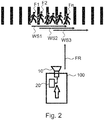
- the Fig. 2 shows a schematic representation of a device for starting assistance for a motor vehicle according to a further embodiment of the present invention.
- the start-up assistance device 20 calculated an expected route, for example a first route WS1, a second route WS2, and a third route WS3, individual pedestrians F1, F2, ..., Fn from group G of pedestrians F1, F2, .. ., Fn assigned, the pedestrians F1, F2, ..., Fn crossing the zebra crossing.
- an expected route for example a first route WS1, a second route WS2, and a third route WS3, individual pedestrians F1, F2, ..., Fn from group G of pedestrians F1, F2, .. ., Fn assigned, the pedestrians F1, F2, ..., Fn crossing the zebra crossing.
- the start-up assistance device 20 now determines possible intersection points between the route FR of the motor vehicle and the distances WS1, WS2, WS3 of the pedestrians.
- the start-up assistance device has determined intersection or intersection points between the driving routes and the routes and has consequently shifted a starting time for starting the motor vehicle.
- the Fig. 3 shows a schematic representation of a device for starting assistance for a motor vehicle.
- the start-up assistance device 20 can determine that the motor vehicle is still sufficiently far from the crosswalk - for example 12 m - and thus a starting time for starting the motor vehicle can be defined without the safety distance between the vehicle and pedestrian F1 falling below a sufficient distance (for example 8 m) becomes.
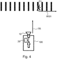
- the Fig. 4 shows a schematic representation of a device for starting assistance for a motor vehicle.
- the starting assistance device 20 has determined a driving route of the motor vehicle. Furthermore, the Start-up assistance device 20 determines a distance WS1 for pedestrian F1 located on the crosswalk.
- the starting assistance device 20 has determined a starting time for starting the motor vehicle based on the determined route WS1 and based on the determined anticipated driving route FR.
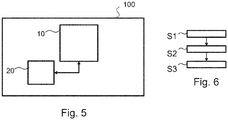
- the Fig. 5 shows a schematic representation of a device for starting assistance for a motor vehicle according to a further embodiment of the present invention.
- the device 100 comprises a surroundings detection device 10 and a starting assistance device 20.
- the environment detection device 10 is designed, for example, to capture an image of an environment of the motor vehicle.
- the environment detection device 10 is designed, for example, as an optical camera system, as an imaging radar system or as an imaging ultrasound system.
- the environment detection device 10 can also be designed as a combination of an optical camera system and / or an imaging radar system and / or an imaging ultrasound system.
- the start-up assistance device 20 is designed, for example, to be based on the captured image of the surroundings Motor vehicle to determine a movement and / or a position of a pedestrian F1, F2, ..., Fn and based on the determined movement and / or the determined position of the pedestrian F1, F2, ..., Fn a starting time for starting the motor vehicle to determine.
- the starting assistance device 20 is designed, for example, to determine a movement and / or a position of a group G of pedestrians F1, F2,..., Fn based on the recorded image of the surroundings of the motor vehicle and based on the determined movement and / or the determined position of group G of pedestrians F1, F2, ..., Fn to determine the starting time for starting the motor vehicle.
- the Fig. 6 shows a schematic representation of a method for starting assistance for a motor vehicle according to a further embodiment of the present invention.
- the start-up assistance process includes the following process steps, for example: As a first step of the method, an image S1 of an environment of the motor vehicle is acquired using an environment detection device 10.
- a movement and / or a position of a pedestrian F1, F2,..., Fn is determined, for example, based on the captured image of the surroundings of the motor vehicle with the aid of a start-up assistance device 20.
- S3 determines a start time for starting the Motor vehicle based on the determined movement and / or the determined position of the pedestrian.
Landscapes
- Engineering & Computer Science (AREA)
- Physics & Mathematics (AREA)
- Transportation (AREA)
- Mechanical Engineering (AREA)
- General Physics & Mathematics (AREA)
- Automation & Control Theory (AREA)
- Mathematical Physics (AREA)
- Multimedia (AREA)
- Theoretical Computer Science (AREA)
- Traffic Control Systems (AREA)
- Electric Propulsion And Braking For Vehicles (AREA)
Description
Die vorliegende Erfindung betrifft Anfahrassistenten und Fahrerassistenzsysteme für Kraftfahrzeuge, welche den Autofahrer beim Anfahren unterstützen. Insbesondere betrifft die vorliegende Erfindung eine Vorrichtung und ein Verfahren zur Anfahrassistenz für ein Kraftfahrzeug.The present invention relates to start-up assistants and driver assistance systems for motor vehicles, which assist the driver when starting. In particular, the present invention relates to a device and a method for starting assistance for a motor vehicle.
Fahrerassistenzsysteme und Anfahrassistenten für Kraftfahrzeuge erhöhen bei Kraftfahrzeugen den Komfort für den Fahrer beim Anfahren. Anfahrassistenten für Kraftfahrzeuge können mit einer automatischen Haltefunktion des Kraftfahrzeugs verbunden werden. Durch die automatische Haltefunktion und den Anfahrassistenten wird die Betriebs- oder Feststellbremsanlage automatisch bei Stillstand des Fahrzeugs angesteuert, um ungewolltes Wegrollen zu verhindern.Driver assistance systems and start-up assistants for motor vehicles increase the comfort for the driver when starting. Starting assistants for motor vehicles can be connected to an automatic stop function of the motor vehicle. Thanks to the automatic stop function and the start-up assistant, the service or parking brake system is automatically activated when the vehicle is at a standstill to prevent it from rolling away unintentionally.
Als Stand der Technik ist die Offenlegungsschrift
Die Offenlegungsschrift
Es ist eine Aufgabe der vorliegenden Erfindung, eine verbesserte Vorrichtung und ein verbessertes Verfahren zur Anfahrassistenz für ein Kraftfahrzeug bereitzustellen.It is an object of the present invention to provide an improved device and an improved method for starting assistance for a motor vehicle.
Diese Aufgabe wird durch die Gegenstände der unabhängigen Patentansprüche gelöst. Ausführungsformen und Weiterbildungen sind den abhängigen Patentansprüchen, der Beschreibung und den Figuren der Zeichnungen zu entnehmen.This object is solved by the subject matter of the independent claims. Embodiments and developments can be found in the dependent claims, the description and the figures in the drawings.
Ein erster Aspekt der vorliegenden Erfindung betrifft eine Vorrichtung zur Anfahrassistenz für ein Kraftfahrzeug, wobei die Vorrichtung umfasst: eine Umfelderfassungseinrichtung, welche dazu ausgelegt ist, ein Abbild eines Umfeldes des Kraftfahrzeuges zu erfassen; und eine Anfahrassistenzeinrichtung, welche dazu ausgelegt ist, basierend auf dem erfassten Abbild des Umfeldes des Kraftfahrzeuges eine Bewegung und/oder eine Position eines Fußgängers zu ermitteln und basierend auf der ermittelten Bewegung und/oder der ermittelten Position des Fußgängers einen Startzeitpunkt zum Starten des Kraftfahrzeuges zu bestimmen.A first aspect of the present invention relates to a device for starting assistance for a motor vehicle, the device comprising: an environment detection device which is designed to detect an image of an environment of the motor vehicle; and a start-up assistance device, which is designed to determine a movement and / or a position of a pedestrian based on the recorded image of the surroundings of the motor vehicle and based on the determined movement and / or the determined position of the pedestrian to determine a starting time for starting the motor vehicle.
In anderen Worten ausgedrückt, die Vorrichtung zur Anfahrassistenz für ein Kraftfahrzeug ist dazu ausgelegt, dass eine Kollision mit Fußgängern beim Anfahren vermieden wird.In other words, the device for starting assistance for a motor vehicle is designed to avoid a collision with pedestrians when starting off.
Die Vorrichtung kann dazu ausgebildet sein, einen ausreichenden Sicherheitsabstand zu einem Fußgänger und/oder zu einer Gruppe von Fußgängern einzuhalten.The device can be designed to maintain a sufficient safety distance from a pedestrian and / or from a group of pedestrians.
Die Vorrichtung kann vorteilhaft mit Anfahrassistenten und Fahrerassistenzsystemen gekoppelt werden, welche den Autofahrer beim Anfahren unterstützen.The device can advantageously be coupled with starting assistants and driver assistance systems which support the driver when starting off.
Dabei passt die Vorrichtung zur Anfahrassistenz automatisch die Geschwindigkeit und/oder den Zeitpunkt des Anfahrens des Kraftfahrzeuges an eine im Umfeld des Kraftfahrzeugs vorherrschende Verkehrsdichte bzw. an ein Vorhandensein von Fußgängern oder von sonstigen Hindernissen an.The device for starting assistance automatically adjusts the speed and / or the time of starting the motor vehicle to a traffic density prevailing in the surroundings of the motor vehicle or to the presence of pedestrians or other obstacles.
Die vorliegende Erfindung ermöglicht vorteilhaft ein entspanntes Anfahren. Die vorliegende Erfindung ermöglicht vorteilhaft, dass das Kraftfahrzeug selbstständig anfahren kann, auch im Falle eines regen Fußgängerverkehrs vor dem Kraftfahrzeug. Die notwendigen Daten kann die Vorrichtung von einer beispielsweise hinter dem Kühlergrill angebrachten optischen Sensoreinrichtung bzw. einer bildgebenden Sensoreinrichtung erhalten.The present invention advantageously enables relaxed starting. The present invention advantageously enables the motor vehicle to start up independently, even in the event of heavy pedestrian traffic in front of the motor vehicle. The device can receive the necessary data from, for example, an optical sensor device or an imaging sensor device attached behind the radiator grille.
Ferner kann die Vorrichtung weitere bildgebende Sensoren umfassen, welche beispielsweise zwischen Innenspiegel und Frontscheibe in einem Gehäuse montiert werden.Furthermore, the device can comprise further imaging sensors, which are mounted, for example, between the inside mirror and the front window in a housing.
Ferner kann die Vorrichtung einen Signalgeber umfassen, welcher den Fahrer warnt, wenn ein Fußgänger zu nah, das heißt innerhalb eines ausreichenden Sicherheitsabstands zum Fahrzeug sich befindet. Beispielsweise kann das von den Sensoren überwachte Umfeld des Kraftfahrzeugs einen Bereich von bis zu 120 m oder bis zu 80 m oder bis zu 40 m vom Fahrzeug aus umfassen. Der Sicherheitsabstand kann beispielsweise bis zu 15 m oder bis zu 10 m oder bis zu 5 m betragen.Furthermore, the device can comprise a signal generator which warns the driver if a pedestrian is too close, that is to say within a sufficient safety distance from the vehicle. For example, the surroundings of the motor vehicle monitored by the sensors can encompass a range of up to 120 m or up to 80 m or up to 40 m from the vehicle. The safety distance can be, for example, up to 15 m or up to 10 m or up to 5 m.
Nach einem weiteren zweiten Aspekt der vorliegenden Erfindung wird ein Verfahren zur Anfahrassistenz für ein Kraftfahrzeug bereitgestellt, wobei das Verfahren folgende Verfahrensschritte umfasst:
Als ein erster Schritt des Verfahrens erfolgt ein Erfassen eines Abbilds eines Umfeldes des Kraftfahrzeuges mithilfe von einer Umfelderfassungseinrichtung.According to a further second aspect of the present invention, a method for starting assistance for a motor vehicle is provided, the method comprising the following method steps:
As a first step of the method, an image of an environment of the motor vehicle is acquired using an environment detection device.
Als ein zweiter Schritt des Verfahrens erfolgt ein Ermitteln einer Bewegung und/oder einer Position eines Fußgängers basierend auf dem erfassten Abbild des Umfeldes des Kraftfahrzeuges mithilfe von einer Anfahrassistenzeinrichtung.As a second step of the method, a movement and / or a position of a pedestrian is determined based on the recorded image of the surroundings of the motor vehicle with the aid of a start-up assistance device.
Als ein dritter Schritt des Verfahrens erfolgt ein Bestimmen eines Startzeitpunkts zum Starten des Kraftfahrzeuges basierend auf der ermittelten Bewegung und/oder der ermittelten Position des Fußgängers.As a third step of the method, a starting time for starting the motor vehicle is determined based on the determined movement and / or the determined position of the pedestrian.
In einer ersten Alternative der vorliegenden Erfindung ist vorgesehen, dass die Anfahrassistenzeinrichtung dazu ausgelegt ist, basierend auf dem erfassten Abbild des Umfeldes des Kraftfahrzeuges eine Bewegung und/oder eine Position einer Gruppe von Fußgängern zu ermitteln und basierend auf der ermittelten Bewegung und/oder der ermittelten Position der Gruppe von Fußgängern den Startzeitpunkt zum Starten des Kraftfahrzeuges zu bestimmen. Das Starten des Kraftfahrzeugs kann dabei eine Initialisierung und ein Ausführen von verschiedenen Prozeduren von Anfahrassistenzsystemen des Kraftfahrzeuges umfassen.In a first alternative of the present invention it is provided that the starting assistance device is designed to be based on the captured image of the To determine a movement and / or a position of a group of pedestrians around the motor vehicle and to determine the starting time for starting the motor vehicle based on the determined movement and / or the determined position of the group of pedestrians. The starting of the motor vehicle can include initialization and execution of various procedures of start-up assistance systems of the motor vehicle.
Ferner kann das Starten des Kraftfahrzeuges auch das Anfahren, d.h. das Bewegen des Kraftfahrzeuges umfassen, in anderen Worten ausgedrückt, das Starten des Kraftfahrzeugs kann eine Beschleunigung des Kraftfahrzeuges umfassen.Furthermore, starting the motor vehicle can also start, i.e. moving the motor vehicle, in other words, starting the motor vehicle may include accelerating the motor vehicle.
Dies ermöglicht vorteilhaft, neben einem einzelnen Fußgänger auch eine Gruppe von Fußgängern zu identifizieren und einen ausreichenden Sicherheitsabstand zwischen Fußgängern und Kraftfahrzeug zu gewährleisten, so dass das Anfahren des Kraftfahrzeugs gefahrlos erfolgen kann, d.h. unter Einhaltung des vordefinierten Sicherheitsabstandes.This advantageously makes it possible to identify a group of pedestrians in addition to a single pedestrian and to ensure a sufficient safety distance between pedestrians and the motor vehicle, so that the motor vehicle can be started safely, i.e. in compliance with the predefined safety distance.
In einer zweiten Alternative der vorliegenden Erfindung ist vorgesehen, dass die Anfahrassistenzeinrichtung dazu ausgelegt ist, basierend auf dem erfassten Abbild des Umfeldes des Kraftfahrzeuges eine voraussichtliche Fahrroute des Kraftfahrzeuges innerhalb des Umfeld des Kraftfahrzeuges zu bestimmen und eine voraussichtliche Wegstrecke des Fußgängers oder der Gruppe von Fußgängern zu bestimmen und basierend auf der ermittelten voraussichtlichen Fahrroute und der ermittelten voraussichtlichen Wegstrecke den Startzeitpunkt zum Starten des Kraftfahrzeuges zu bestimmen. Dies ermöglicht vorteilhaft, eine Kollisionsvermeidung bereitzustellen und Kollisionen oder Zusammenstöße von Fußgängern und dem Kraftfahrzeug zu vermeiden.In a second alternative of the present invention, it is provided that the start-up assistance device is designed to determine an expected route of the motor vehicle within the environment of the motor vehicle on the basis of the recorded image of the surroundings of the motor vehicle and to determine a probable distance traveled by the pedestrian or the group of pedestrians determine and determine the starting time for starting the motor vehicle on the basis of the ascertained probable driving route and the ascertained probable route. This advantageously enables collision avoidance To provide and avoid collisions or collisions between pedestrians and the motor vehicle.
Vorteilhafte Ausgestaltungen der vorliegenden Erfindung sind in den Unteransprüchen gekennzeichnet.Advantageous embodiments of the present invention are characterized in the subclaims.
In einer vorteilhaften Ausführungsform der vorliegenden Erfindung ist vorgesehen, dass die Anfahrassistenzeinrichtung dazu ausgelegt ist, eine Kollisionsvermeidung basierend auf der ermittelten voraussichtlichen Fahrroute und der voraussichtlichen Wegstrecke bereitzustellen.In an advantageous embodiment of the present invention, it is provided that the start-up assistance device is designed to provide collision avoidance based on the ascertained probable driving route and the probable route.
In einer weiteren vorteilhaften Ausführungsform der vorliegenden Erfindung ist vorgesehen, dass die Umfelderfassungseinrichtung ein optisches Kamerasystem, ein bildgebendes Radarsystem oder ein bildgebendes Ultraschallsystem umfasst.In a further advantageous embodiment of the present invention, it is provided that the environment detection device comprises an optical camera system, an imaging radar system or an imaging ultrasound system.
Dies ermöglicht vorteilhaft, Umfelddaten und Umfeldinformationen zu sammeln und eine automatische Fußgängererkennung bereitzustellen. Dabei kann die Umfelderfassungseinrichtung dazu ausgebildet sein, Objekte auf dem Abbild zu erkennen und Fußgänger auf dem Abbild zu identifizieren. Beispielsweise können Personen in bis zu 75 m oder in bis zu 35 m oder in bis zu 25 m Entfernung erfasst und mittels Bildverarbeitung oder Computer-unterstützter Bilderkennung als Personen oder Fußgänger identifiziert werden.This advantageously enables environment data and environment information to be collected and automatic pedestrian detection to be provided. The Environment detection device can be designed to recognize objects on the image and to identify pedestrians on the image. For example, people up to 75 m or up to 35 m or up to 25 m away can be detected and identified as people or pedestrians by means of image processing or computer-assisted image recognition.
Die Umfelderfassungseinrichtung kann dazu ausgebildet sein, Bewegungsmuster von Fußgängern zu erkennen und somit die Bewegung und/oder die Position der Fußgänger zu ermitteln.The environment detection device can be designed to recognize movement patterns of pedestrians and thus to determine the movement and / or the position of the pedestrians.
Das bildgebende Radarsystem kann beispielsweise eine 76-GHz-Radareinheit umfassen.The imaging radar system can include, for example, a 76 GHz radar unit.
Das bildgebende Radarsystem kann beispielsweise dazu ausgebildet sein, stationäre Objekte im Nahbereich oder im Umfeld des Kraftfahrzeuge zu erfassen und im Frequenzbereich von 24 GHz oder 77 GHz Radarsignale zu senden und Rückstreuungen zu empfange. Das bildgebende Radarsystem hat beispielsweise einen Abstrahlwinkel im Azimut bei +/-80° und in der vertikalen Abstrahlcharakteristik bei etwa +/-20°.The imaging radar system can be designed, for example, to detect stationary objects in the vicinity or in the vicinity of the motor vehicle and to transmit radar signals in the frequency range of 24 GHz or 77 GHz and to receive backscattering. For example, the imaging radar system has a radiation angle in the azimuth at +/- 80 ° and in the vertical radiation characteristic at approximately +/- 20 °.
Das optische Kamerasystem kann beispielsweise eine CMOS-Kamera umfassen, Abkürzung CMOS steht für "Complementary metal-oxide-semiconductor", aus dem Englischen: "sich ergänzender Metall-Oxid-Halbleiter".The optical camera system can include, for example, a CMOS camera, abbreviation CMOS stands for "Complementary metal-oxide-semiconductor", from the English: "Complementary metal-oxide semiconductor".
Die beschriebenen Ausgestaltungen und Weiterbildungen lassen sich beliebig miteinander kombinieren.The embodiments and further developments described can be combined with one another as desired.
Weitere mögliche Ausgestaltungen, Weiterbildungen und Implementierungen der vorliegenden Erfindung umfassen auch nicht explizit genannte Kombinationen von zuvor oder im Folgenden bezüglich der Ausführungsbeispiele beschriebenen Merkmale der vorliegenden Erfindung.Further possible refinements, developments and implementations of the present invention also include combinations of previously or in the said which are not explicitly mentioned The following features of the present invention described with reference to the exemplary embodiments.
Die beiliegenden Zeichnungen sollen ein weiteres Verständnis der Ausführungsformen der vorliegenden Erfindung vermitteln. Die beiliegenden Zeichnungen veranschaulichen Ausführungsformen und dienen im Zusammenhang mit der Beschreibung der Erklärung von Konzepten der vorliegenden Erfindung.The accompanying drawings are intended to provide further understanding of the embodiments of the present invention. The accompanying drawings illustrate embodiments and, in connection with the description, serve to explain concepts of the present invention.
Andere Ausführungsformen und viele der genannten Vorteile ergeben sich im Hinblick auf die Figuren der Zeichnungen. Die dargestellten Elemente der Figuren der Zeichnungen sind nicht notwendigerweise maßstabsgetreu zueinander gezeigt.Other embodiments and many of the advantages mentioned arise with regard to the figures of the drawings. The elements shown in the figures of the drawings are not necessarily shown to scale with respect to one another.
Es zeigen:
- Fig. 1
- eine schematische Darstellung einer Vorrichtung zur Fahrerassistenz für ein Kraftfahrzeug bei der Anfahrt vor einem Zebrastreifen, welcher von einer Gruppe von Fußgängern überquert wird;
- Fig. 2
- zeigt eine schematische Darstellung einer Vorrichtung zur Anfahrassistenz für ein Kraftfahrzeug gemäß einer weiteren Ausführungsform der vorliegenden Erfindung;
- Fig. 3
- zeigt eine schematische Darstellung einer Vorrichtung zur Anfahrassistenz für ein Kraftfahrzeug, wobei das Kraftfahrzeug vor einem Zebrastreifen mit einem einzelnen Fußgänger anfährt;
- Fig. 4
- zeigt eine schematische Darstellung einer Vorrichtung zur Fahrerassistenz für ein Kraftfahrzeug gemäß einer weiteren Ausführungsform der vorliegenden Erfindung;
- Fig. 5
- zeigt eine schematische Darstellung einer Vorrichtung zur Anfahrassistenz für ein Kraftfahrzeug gemäß einer weiteren Ausführungsform der vorliegenden Erfindung; und
- Fig. 6
- zeigt eine schematische Darstellung einer Vorrichtung zur Anfahrassistenz gemäß einer weiteren Ausführungsform der vorliegenden Erfindung.
- Fig. 1
- is a schematic representation of a device for driver assistance for a motor vehicle when approaching a zebra crossing, which is crossed by a group of pedestrians;
- Fig. 2
- shows a schematic representation of a device for starting assistance for a motor vehicle according to a further embodiment of the present invention;
- Fig. 3
- shows a schematic representation of a device for starting assistance for a motor vehicle, the motor vehicle starting in front of a crosswalk with a single pedestrian;
- Fig. 4
- shows a schematic representation of a device for driver assistance for a motor vehicle according to a further embodiment of the present invention;
- Fig. 5
- shows a schematic representation of a device for starting assistance for a motor vehicle according to a further embodiment of the present invention; and
- Fig. 6
- shows a schematic representation of a device for starting assistance according to a further embodiment of the present invention.
In den Figuren der Zeichnungen bezeichnen gleiche Bezugszeichen gleiche oder funktionsgleiche Elemente, Bauteile, Komponenten oder Verfahrensschritte, soweit nichts Gegenteiliges angegeben ist.In the figures of the drawings, identical reference symbols designate identical or functionally identical elements, components, components or method steps, unless stated otherwise.
Die
Die Vorrichtung 100 umfasst beispielsweise eine Umfelderfassungseinrichtung 10 und eine Anfahrassistenzeinrichtung 20.The
Bei dem in der
Diese von den Fußgängern F1, F2, ..., Fn vorgenommene Überquerung des Zebrastreifens wird von der Umfelderfassungseinrichtung 10 erfasst.This crossing of the zebra crossing carried out by the pedestrians F1, F2,..., Fn is detected by the
Die Umfelderfassungseinrichtung 10 kann beispielsweise ein Abbild in Form eines optischen Kamerabildes oder eines Radarbildes oder in Form eines Ultraschallumgebungsbildes aufnehmen, auf dem die Fußgänger F1, F2, ..., Fn beim Überqueren des Zebrastreifens im Umfeld des Kraftfahrzeuges abgebildet sind.The
Die
Bei der in der
Ferner wurde von der Anfahrassistenzeinrichtung 20 eine voraussichtliche Wegstrecke, beispielsweise eine erste Wegstrecke WS1, eine zweite Wegstrecke WS2, sowie eine dritte Wegstrecke WS3, einzelnen Fußgängern F1, F2, ..., Fn aus der Gruppe G von Fußgängern F1, F2, ..., Fn zugeordnet, wobei die Fußgänger F1, F2, ..., Fn den Zebrastreifen überqueren.Furthermore, the start-up
Die Anfahrassistenzeinrichtung 20 ermittelt nun mögliche Schnittpunkte zwischen der Fahrroute FR des Kraftfahrzeugs und den Wegstrecken WS1, WS2, WS3 der Fußgänger.The start-up
Im vorliegenden Fall hat die Anfahrassistenzeinrichtung dabei Schnitt- oder Kreuzungspunkte zwischen den Fahrrouten und den Wegstrecken festgestellt und folglich einen Startzeitpunkt zum Starten des Kraftfahrzeuges verschoben.In the present case, the start-up assistance device has determined intersection or intersection points between the driving routes and the routes and has consequently shifted a starting time for starting the motor vehicle.
Die weiteren Bezugszeichen, wie in der
Die
In der in der
Ferner kann die Anfahrassistenzeinrichtung 20 ermitteln, dass das Kraftfahrzeug noch hinreichend entfernt ist von dem Zebrastreifen - beispielsweise 12 m - und somit kann ein Startzeitpunkt zum Starten des Kraftfahrzeuges festgelegt werden, ohne dass ein ausreichender Sicherheitsabstand - beispielsweise 8 m - zwischen Fahrzeug und Fußgänger F1 unterschritten wird.Furthermore, the start-up
Die weiteren Bezugszeichen, wie in der
Die
Die Anfahrassistenzeinrichtung 20 hat eine Fahrroute des Kraftfahrzeuges ermittelt. Ferner hat die Anfahrassistenzeinrichtung 20 eine Wegstrecke WS1 für den auf dem Zebrastreifen befindlichen Fußgänger F1 ermittelt.The starting
Ferner hat die Anfahrassistenzeinrichtung 20 basierend auf der ermittelten Wegstrecke WS1 und basierend auf der ermittelten voraussichtlichen Fahrroute FR einen Startzeitpunkt zum Starten des Kraftfahrzeuges bestimmt.Furthermore, the starting
Die weiteren Bezugszeichen, wie in der
Die
Die Vorrichtung 100 umfasst eine Umfelderfassungseinrichtung 10 und eine Anfahrassistenzeinrichtung 20.The
Die Umfelderfassungseinrichtung 10 ist beispielsweise dazu ausgelegt, ein Abbild eines Umfelds des Kraftfahrzeuges zu erfassen. Die Umfelderfassungseinrichtung 10 ist beispielsweise als ein optisches Kamerasystem, als ein bildgebendes Radarsystem oder als ein bildgebendes Ultraschallsystem ausgebildet.The
Ferner kann die Umfelderfassungseinrichtung 10 auch als eine Kombination von einem optischen Kamerasystem und/oder einem bildgebenden Radarsystem und/oder einem bildgebenden Ultraschallsystem ausgebildet sein.Furthermore, the
Die Anfahrassistenzeinrichtung 20 ist beispielsweise dazu ausgebildet, basierend auf dem erfassten Abbild des Umfelds Kraftfahrzeuges eine Bewegung und/oder eine Position eines Fußgängers F1, F2, ..., Fn zu ermitteln und basierend auf der ermittelten Bewegung und/oder der ermittelten Position des Fußgängers F1, F2, ..., Fn einen Startzeitpunkt zum Starten des Kraftfahrzeuges zu bestimmen.The start-up
Die Anfahrassistenzeinrichtung 20 ist beispielsweise dazu ausgebildet, basierend auf dem erfassten Abbild des Umfeldes des Kraftfahrzeuges eine Bewegung und/oder eine Position einer Gruppe G von Fußgängern F1, F2, ..., Fn zu ermitteln und basierend auf der ermittelten Bewegung und/oder der ermittelten Position der Gruppe G von Fußgängern F1, F2, ..., Fn den Startzeitpunkt zum Starten des Kraftfahrzeuges zu bestimmen.The starting
Die
Das Verfahren zur Anfahrassistenz umfasst beispielsweise folgende Verfahrensschritte:
Als ein erster Schritt des Verfahrens erfolgt ein Erfassen S1 eines Abbilds eines Umfeldes des Kraftfahrzeuges mithilfe von einer Umfelderfassungseinrichtung 10.The start-up assistance process includes the following process steps, for example:
As a first step of the method, an image S1 of an environment of the motor vehicle is acquired using an
Als ein zweiter Verfahrensschritt erfolgt beispielsweise ein Ermitteln S2 einer Bewegung und/oder einer Position eines Fußgängers F1, F2, ..., Fn basierend auf dem erfassten Abbild des Umfeldes des Kraftfahrzeuges mithilfe von einer Anfahrassistenzeinrichtung 20.As a second method step, a movement and / or a position of a pedestrian F1, F2,..., Fn is determined, for example, based on the captured image of the surroundings of the motor vehicle with the aid of a start-up
Als ein dritter Schritt des Verfahrens erfolgt beispielsweise ein Bestimmen S3 eines Startzeitpunkts zum Starten des Kraftfahrzeuges basierend auf der ermittelten Bewegung und/oder der ermittelten Position des Fußgängers.As a third step of the method, for example, S3 determines a start time for starting the Motor vehicle based on the determined movement and / or the determined position of the pedestrian.
Obwohl die vorliegende Erfindung anhand bevorzugter Ausführungsbeispiele vorstehend beschrieben wurde, ist sie nicht darauf beschränkt, sondern auf vielfältige Art und Weise modifizierbar. Insbesondere lässt sich die vorliegende Erfindung in mannigfaltiger Weise verändern oder modifizieren, ohne vom Kern der Erfindung abzuweichen.Although the present invention has been described above on the basis of preferred exemplary embodiments, it is not restricted to these but can be modified in a variety of ways. In particular, the present invention can be changed or modified in a variety of ways without departing from the essence of the invention.
Ergänzend sei darauf hingewiesen, dass "umfassend" und "aufweisend" keine anderen Elemente oder Schritte ausschließt und "eine" oder "ein" keine Vielzahl ausschließt.In addition, it should be pointed out that “comprising” and “having” do not exclude other elements or steps, and “a” or “an” does not exclude a plurality.
Ferner sei darauf hingewiesen, dass Merkmale oder Schritte, die mit Verweis auf eines der obigen Ausführungsbeispiele beschrieben worden sind, auch in Kombination mit anderen Merkmalen oder Schritten anderer oben beschriebener Ausführungsbeispiele verwendet werden können. Bezugszeichen in den Ansprüchen sind nicht als Einschränkungen anzusehen.Furthermore, it should be pointed out that features or steps that have been described with reference to one of the above exemplary embodiments can also be used in combination with other features or steps of other exemplary embodiments described above. Reference signs in the claims are not to be regarded as restrictions.
Claims (6)
- A device (100) for start assistance for a motor vehicle, wherein the device (100) comprises:- a surroundings detection apparatus (10) which is designed to detect an image of the environment of the motor vehicle; and- a start assistance apparatus (20) which is designedi) to establish a movement and/or a position of a pedestrian (F1, F2, ..., Fn) and of a group (G) of pedestrians (F1, F2, ..., Fn)
on the basis of the detected image of the environment of the motor vehicle and to determine a starting time for starting the motor vehicle on the basis of the established movement and/or the established position of the pedestrian (F1, F2, ..., Fn) and of a group (G) of pedestrians (F1, F2, ..., Fn) orii) to determine a likely route (FR) of the motor vehicle within the environment of the motor vehicle and to determine a likely path (WS1, WS2, ..., WSn) of the pedestrian (F1, F2, ..., Fn) or the group (G) of pedestrians (F1, F2, ..., Fn) and to determine the starting time for starting the motor vehicle on the basis of the established likely route and the established likely path. - The device according to Claim 1,
wherein the start assistance apparatus (20) is designed to provide a collision avoidance on the basis of the established likely route (FR) and the likely path (WS1, WS2, ..., WSn). - The device according to any one of the preceding claims, wherein the surroundings detection apparatus (10) comprises an optical camera system, an imaging radar system, or an imaging ultrasound system.
- A motor vehicle which comprises a device according to any one of the preceding Claims 1 to 3.
- A method for start assistance for a motor vehicle, wherein the method comprises the following method steps:- detecting (S1) an image of the environment of the motor vehicle with the aid of surroundings detection apparatus (10); andi) establishing (S2) a movement and/or a position of a pedestrian (F1, F2, ..., Fn) and of a group (G) of pedestrians (F1, F2, ..., Fn) on the basis of the detected image of the environment of the motor vehicle with the aid of a start assistance apparatus (20); and determining (S3) a starting time for starting the motor vehicle on the basis of the established movement and/or the established position of the pedestrian (F1, F2, ..., Fn) and of a group (G) of pedestrians (F1, F2, ..., Fn),
orii) determining a likely route (FR) of the motor vehicle within the environment of the motor vehicle on the basis of the detected image of the environment of the motor vehicle and determining a likely path of the pedestrian or of the group (G) of pedestrians (F1, F2, ..., Fn) on the basis of the detected image of the environment of the motor vehicle, and determining the starting time for starting the motor vehicle on the basis of the established likely route (FR) and the likely path (WS1, WS2, ..., WSn). - The method according to Claim 5,
wherein the method additionally comprises the following method step:- providing a collision avoidance on the basis of the established likely route (FR) and the likely path (WS1, WS2, ..., WSn).
Priority Applications (4)
| Application Number | Priority Date | Filing Date | Title |
|---|---|---|---|
| EP15465540.1A EP3144919B1 (en) | 2015-09-18 | 2015-09-18 | Device and method for start assistance for a motor vehicle |
| PCT/EP2016/066880 WO2017045802A1 (en) | 2015-09-18 | 2016-07-15 | Device and method for start assistance for a motor vehicle |
| CN201680053178.XA CN108028019B (en) | 2015-09-18 | 2016-07-15 | Device and method for starting assistance of a motor vehicle |
| US15/923,131 US20180204462A1 (en) | 2015-09-18 | 2018-03-16 | Device and method for start assistance for a motor vehicle |
Applications Claiming Priority (1)
| Application Number | Priority Date | Filing Date | Title |
|---|---|---|---|
| EP15465540.1A EP3144919B1 (en) | 2015-09-18 | 2015-09-18 | Device and method for start assistance for a motor vehicle |
Publications (2)
| Publication Number | Publication Date |
|---|---|
| EP3144919A1 EP3144919A1 (en) | 2017-03-22 |
| EP3144919B1 true EP3144919B1 (en) | 2020-06-24 |
Family
ID=54291239
Family Applications (1)
| Application Number | Title | Priority Date | Filing Date |
|---|---|---|---|
| EP15465540.1A Active EP3144919B1 (en) | 2015-09-18 | 2015-09-18 | Device and method for start assistance for a motor vehicle |
Country Status (4)
| Country | Link |
|---|---|
| US (1) | US20180204462A1 (en) |
| EP (1) | EP3144919B1 (en) |
| CN (1) | CN108028019B (en) |
| WO (1) | WO2017045802A1 (en) |
Families Citing this family (5)
| Publication number | Priority date | Publication date | Assignee | Title |
|---|---|---|---|---|
| KR102019001B1 (en) * | 2016-01-29 | 2019-09-05 | 닛산 지도우샤 가부시키가이샤 | Driving control method of vehicle and driving control apparatus of vehicle |
| KR102441060B1 (en) * | 2016-12-13 | 2022-09-06 | 현대자동차주식회사 | Apparatus for preventing pedestrian collision, system having the same and method thereof |
| US11137993B2 (en) * | 2017-01-06 | 2021-10-05 | Hitachi Automotive Systems, Ltd. | Imaging device |
| CN108986504A (en) * | 2018-08-06 | 2018-12-11 | 佛山市苔藓云链科技有限公司 | A kind of intelligent vehicle and its method for restarting |
| CN109017675A (en) * | 2018-08-06 | 2018-12-18 | 佛山市苔藓云链科技有限公司 | A kind of intelligent vehicle and Vehicular intelligent starting method |
Family Cites Families (26)
| Publication number | Priority date | Publication date | Assignee | Title |
|---|---|---|---|---|
| US6580385B1 (en) * | 1999-05-26 | 2003-06-17 | Robert Bosch Gmbh | Object detection system |
| EP1083076A3 (en) * | 1999-09-07 | 2005-01-12 | Mazda Motor Corporation | Display apparatus for vehicle |
| US7561966B2 (en) * | 2003-12-17 | 2009-07-14 | Denso Corporation | Vehicle information display system |
| DE102004016981A1 (en) * | 2004-04-07 | 2005-10-27 | Robert Bosch Gmbh | Method and device for warning the driver of a motor vehicle |
| JP2006259895A (en) * | 2005-03-15 | 2006-09-28 | Omron Corp | Start control device for movable body |
| DE102005045017A1 (en) * | 2005-09-21 | 2007-03-22 | Robert Bosch Gmbh | Method and driver assistance system for sensor-based approach control of a motor vehicle |
| JP4743275B2 (en) * | 2006-03-01 | 2011-08-10 | トヨタ自動車株式会社 | Own vehicle route determination method and own vehicle route determination device |
| DE102009049408A1 (en) * | 2008-10-21 | 2010-04-22 | Continental Teves Ag & Co. Ohg | Sensor system for autonomous starting of motor vehicle, has camera system monitoring area before vehicle during standstill condition of vehicle, and preventing automatic starting of vehicle when objects move in predetermined area |
| DE102008061760A1 (en) * | 2008-12-12 | 2010-06-17 | Daimler Ag | Device for monitoring an environment of a vehicle |
| DE102009024062A1 (en) * | 2009-06-05 | 2010-12-09 | Valeo Schalter Und Sensoren Gmbh | Apparatus and method for displaying objects in a vehicle environment |
| CN101934790B (en) * | 2009-07-01 | 2015-10-14 | 福特环球技术公司 | The starting that the starting/stopping of vehicle controls stops |
| DE102009057836B4 (en) * | 2009-12-10 | 2013-02-21 | Continental Teves Ag & Co. Ohg | Emergency braking assistance system to assist a driver of a vehicle when starting |
| WO2011129014A1 (en) * | 2010-04-16 | 2011-10-20 | トヨタ自動車株式会社 | Driving support device |
| SE535225C2 (en) * | 2010-10-07 | 2012-05-29 | Scania Cv Ab | Procedure and warning system for objects in connection with a motor vehicle |
| DE102010052304A1 (en) * | 2010-11-23 | 2012-05-24 | Valeo Schalter Und Sensoren Gmbh | Method and device for assisting a driver of a motor vehicle when parking out of a parking space and motor vehicle |
| CN102096803B (en) * | 2010-11-29 | 2013-11-13 | 吉林大学 | Safe state recognition system for people on basis of machine vision |
| DE102011081614A1 (en) * | 2011-08-26 | 2013-02-28 | Robert Bosch Gmbh | Method and device for analyzing a road section to be traveled by a vehicle |
| DE102011086404A1 (en) * | 2011-11-15 | 2013-05-16 | Robert Bosch Gmbh | Method for generating signal representative of release or prohibition of starting of vehicle e.g. motor car, involves recognizing search area around vehicle contour based on detection of color change in presence of object |
| WO2014068671A1 (en) * | 2012-10-30 | 2014-05-08 | トヨタ自動車 株式会社 | Vehicle safety apparatus |
| JP6022983B2 (en) * | 2013-03-29 | 2016-11-09 | 株式会社日本自動車部品総合研究所 | Driving assistance device |
| JP5905846B2 (en) * | 2013-03-29 | 2016-04-20 | 株式会社日本自動車部品総合研究所 | Crossing determination device and program |
| JP5884771B2 (en) * | 2013-05-22 | 2016-03-15 | 株式会社デンソー | Collision mitigation device |
| DE202013006676U1 (en) * | 2013-07-25 | 2014-10-28 | GM Global Technology Operations LLC (n. d. Ges. d. Staates Delaware) | System for warning of a possible collision of a motor vehicle with an object |
| US9988047B2 (en) * | 2013-12-12 | 2018-06-05 | Magna Electronics Inc. | Vehicle control system with traffic driving control |
| DE102014201159A1 (en) * | 2014-01-23 | 2015-07-23 | Robert Bosch Gmbh | Method and device for classifying a behavior of a pedestrian when crossing a roadway of a vehicle and personal protection system of a vehicle |
| DE102014201382A1 (en) * | 2014-01-27 | 2015-07-30 | Robert Bosch Gmbh | Method for operating a driver assistance system and driver assistance system |
-
2015
- 2015-09-18 EP EP15465540.1A patent/EP3144919B1/en active Active
-
2016
- 2016-07-15 WO PCT/EP2016/066880 patent/WO2017045802A1/en active Application Filing
- 2016-07-15 CN CN201680053178.XA patent/CN108028019B/en active Active
-
2018
- 2018-03-16 US US15/923,131 patent/US20180204462A1/en not_active Abandoned
Non-Patent Citations (1)
| Title |
|---|
| None * |
Also Published As
| Publication number | Publication date |
|---|---|
| WO2017045802A1 (en) | 2017-03-23 |
| CN108028019A (en) | 2018-05-11 |
| EP3144919A1 (en) | 2017-03-22 |
| CN108028019B (en) | 2021-08-24 |
| US20180204462A1 (en) | 2018-07-19 |
Similar Documents
| Publication | Publication Date | Title |
|---|---|---|
| EP2620929B1 (en) | Method and apparatus for detecting an exceptional traffic situation | |
| EP3144919B1 (en) | Device and method for start assistance for a motor vehicle | |
| EP2788967B1 (en) | Method for monitoring and signaling a traffic situation in the surroundings of a vehicle | |
| DE102009006335B4 (en) | Method for assisting the driver of a motor vehicle | |
| EP3394844B1 (en) | Method for collision avoidance of a motor vehicle with an emergency vehicle and a related system and motor vehicle | |
| DE102016003438A1 (en) | Driving assistance system of a vehicle and method for controlling the same | |
| DE102017000641A1 (en) | VEHICLE CONTROL DEVICE | |
| WO2015032709A1 (en) | Method and traffic monitoring unit for establishing that a motor vehicle is driving in the wrong direction | |
| DE102014200700A1 (en) | Method and system for detecting an emergency lane situation | |
| DE102016223579A1 (en) | Method for determining data of a traffic situation | |
| WO2008019907A1 (en) | Method and apparatus for driver assistance through the production of lane information for supporting or replacing lane information from a video-based lane information device | |
| DE102016002230B4 (en) | Method for operating a motor vehicle and motor vehicle | |
| EP2021975A1 (en) | Device and method for the determination of the clearance in front of a vehicle | |
| DE102013005404A1 (en) | Method for supporting driver during driving of motor car in three-lane road surface, involves optically marking detected area to be occupied by vehicle during lane changing and/or sudden approach in environment of other vehicle | |
| DE102013015028A1 (en) | Method for operating a vehicle | |
| DE102017205495A1 (en) | Device and method for focusing sensors in the driving dynamic limit range for a motor vehicle | |
| DE102020207928A1 (en) | DEVICE FOR ASSISTING THE DRIVING OF A VEHICLE AND METHOD FOR THEREFORE | |
| DE102010001304A1 (en) | Traffic condition controlling method for e.g. electric car, involves computing probability of crash of car based on kinematic data and performing evasive maneuver by another car when crash is threatened by former car | |
| DE102012208302B4 (en) | Method for providing information about the surroundings of a vehicle | |
| EP1887540B1 (en) | Device and method for avoiding rear-end collisions | |
| DE102016216745A1 (en) | Method for operating a motor vehicle | |
| DE102012220191A1 (en) | Method for supporting driver during transverse guide of vehicle, involves carrying out steering intervention during collision of vehicle with recognized objects, and determining vehicle data through forward facing camera | |
| DE102006040332A1 (en) | Traffic detecting method, involves determining average speed assigned to lanes, and generating warning signal in lanes with intended track change of vehicle, when average speed varies around preset value of speed of vehicle | |
| DE102014208026A1 (en) | METHOD AND DEVICE FOR WARNING TRANSPORT PARTICIPANTS | |
| DE102007007283A1 (en) | Vehicle for recording surroundings makes information on surroundings available to a vehicle's control unit so as to change a vehicle's performance |
Legal Events
| Date | Code | Title | Description |
|---|---|---|---|
| PUAI | Public reference made under article 153(3) epc to a published international application that has entered the european phase |
Free format text: ORIGINAL CODE: 0009012 |
|
| STAA | Information on the status of an ep patent application or granted ep patent |
Free format text: STATUS: THE APPLICATION HAS BEEN PUBLISHED |
|
| AK | Designated contracting states |
Kind code of ref document: A1 Designated state(s): AL AT BE BG CH CY CZ DE DK EE ES FI FR GB GR HR HU IE IS IT LI LT LU LV MC MK MT NL NO PL PT RO RS SE SI SK SM TR |
|
| AX | Request for extension of the european patent |
Extension state: BA ME |
|
| STAA | Information on the status of an ep patent application or granted ep patent |
Free format text: STATUS: REQUEST FOR EXAMINATION WAS MADE |
|
| 17P | Request for examination filed |
Effective date: 20170922 |
|
| RBV | Designated contracting states (corrected) |
Designated state(s): AL AT BE BG CH CY CZ DE DK EE ES FI FR GB GR HR HU IE IS IT LI LT LU LV MC MK MT NL NO PL PT RO RS SE SI SK SM TR |
|
| GRAP | Despatch of communication of intention to grant a patent |
Free format text: ORIGINAL CODE: EPIDOSNIGR1 |
|
| STAA | Information on the status of an ep patent application or granted ep patent |
Free format text: STATUS: GRANT OF PATENT IS INTENDED |
|
| INTG | Intention to grant announced |
Effective date: 20200213 |
|
| GRAJ | Information related to disapproval of communication of intention to grant by the applicant or resumption of examination proceedings by the epo deleted |
Free format text: ORIGINAL CODE: EPIDOSDIGR1 |
|
| GRAP | Despatch of communication of intention to grant a patent |
Free format text: ORIGINAL CODE: EPIDOSNIGR1 |
|
| INTG | Intention to grant announced |
Effective date: 20200421 |
|
| GRAS | Grant fee paid |
Free format text: ORIGINAL CODE: EPIDOSNIGR3 |
|
| GRAA | (expected) grant |
Free format text: ORIGINAL CODE: 0009210 |
|
| STAA | Information on the status of an ep patent application or granted ep patent |
Free format text: STATUS: THE PATENT HAS BEEN GRANTED |
|
| AK | Designated contracting states |
Kind code of ref document: B1 Designated state(s): AL AT BE BG CH CY CZ DE DK EE ES FI FR GB GR HR HU IE IS IT LI LT LU LV MC MK MT NL NO PL PT RO RS SE SI SK SM TR |
|
| REG | Reference to a national code |
Ref country code: GB Ref legal event code: FG4D Free format text: NOT ENGLISH |
|
| REG | Reference to a national code |
Ref country code: CH Ref legal event code: EP |
|
| REG | Reference to a national code |
Ref country code: AT Ref legal event code: REF Ref document number: 1284670 Country of ref document: AT Kind code of ref document: T Effective date: 20200715 |
|
| REG | Reference to a national code |
Ref country code: DE Ref legal event code: R096 Ref document number: 502015012855 Country of ref document: DE |
|
| REG | Reference to a national code |
Ref country code: IE Ref legal event code: FG4D Free format text: LANGUAGE OF EP DOCUMENT: GERMAN |
|
| RAP2 | Party data changed (patent owner data changed or rights of a patent transferred) |
Owner name: CONTINENTAL AUTOMOTIVE GMBH |
|
| PG25 | Lapsed in a contracting state [announced via postgrant information from national office to epo] |
Ref country code: FI Free format text: LAPSE BECAUSE OF FAILURE TO SUBMIT A TRANSLATION OF THE DESCRIPTION OR TO PAY THE FEE WITHIN THE PRESCRIBED TIME-LIMIT Effective date: 20200624 Ref country code: LT Free format text: LAPSE BECAUSE OF FAILURE TO SUBMIT A TRANSLATION OF THE DESCRIPTION OR TO PAY THE FEE WITHIN THE PRESCRIBED TIME-LIMIT Effective date: 20200624 Ref country code: SE Free format text: LAPSE BECAUSE OF FAILURE TO SUBMIT A TRANSLATION OF THE DESCRIPTION OR TO PAY THE FEE WITHIN THE PRESCRIBED TIME-LIMIT Effective date: 20200624 Ref country code: GR Free format text: LAPSE BECAUSE OF FAILURE TO SUBMIT A TRANSLATION OF THE DESCRIPTION OR TO PAY THE FEE WITHIN THE PRESCRIBED TIME-LIMIT Effective date: 20200925 Ref country code: NO Free format text: LAPSE BECAUSE OF FAILURE TO SUBMIT A TRANSLATION OF THE DESCRIPTION OR TO PAY THE FEE WITHIN THE PRESCRIBED TIME-LIMIT Effective date: 20200924 |
|
| REG | Reference to a national code |
Ref country code: LT Ref legal event code: MG4D |
|
| PG25 | Lapsed in a contracting state [announced via postgrant information from national office to epo] |
Ref country code: HR Free format text: LAPSE BECAUSE OF FAILURE TO SUBMIT A TRANSLATION OF THE DESCRIPTION OR TO PAY THE FEE WITHIN THE PRESCRIBED TIME-LIMIT Effective date: 20200624 Ref country code: RS Free format text: LAPSE BECAUSE OF FAILURE TO SUBMIT A TRANSLATION OF THE DESCRIPTION OR TO PAY THE FEE WITHIN THE PRESCRIBED TIME-LIMIT Effective date: 20200624 Ref country code: LV Free format text: LAPSE BECAUSE OF FAILURE TO SUBMIT A TRANSLATION OF THE DESCRIPTION OR TO PAY THE FEE WITHIN THE PRESCRIBED TIME-LIMIT Effective date: 20200624 Ref country code: BG Free format text: LAPSE BECAUSE OF FAILURE TO SUBMIT A TRANSLATION OF THE DESCRIPTION OR TO PAY THE FEE WITHIN THE PRESCRIBED TIME-LIMIT Effective date: 20200924 |
|
| REG | Reference to a national code |
Ref country code: NL Ref legal event code: MP Effective date: 20200624 |
|
| PG25 | Lapsed in a contracting state [announced via postgrant information from national office to epo] |
Ref country code: NL Free format text: LAPSE BECAUSE OF FAILURE TO SUBMIT A TRANSLATION OF THE DESCRIPTION OR TO PAY THE FEE WITHIN THE PRESCRIBED TIME-LIMIT Effective date: 20200624 Ref country code: AL Free format text: LAPSE BECAUSE OF FAILURE TO SUBMIT A TRANSLATION OF THE DESCRIPTION OR TO PAY THE FEE WITHIN THE PRESCRIBED TIME-LIMIT Effective date: 20200624 |
|
| PG25 | Lapsed in a contracting state [announced via postgrant information from national office to epo] |
Ref country code: PT Free format text: LAPSE BECAUSE OF FAILURE TO SUBMIT A TRANSLATION OF THE DESCRIPTION OR TO PAY THE FEE WITHIN THE PRESCRIBED TIME-LIMIT Effective date: 20201026 Ref country code: ES Free format text: LAPSE BECAUSE OF FAILURE TO SUBMIT A TRANSLATION OF THE DESCRIPTION OR TO PAY THE FEE WITHIN THE PRESCRIBED TIME-LIMIT Effective date: 20200624 Ref country code: SM Free format text: LAPSE BECAUSE OF FAILURE TO SUBMIT A TRANSLATION OF THE DESCRIPTION OR TO PAY THE FEE WITHIN THE PRESCRIBED TIME-LIMIT Effective date: 20200624 Ref country code: EE Free format text: LAPSE BECAUSE OF FAILURE TO SUBMIT A TRANSLATION OF THE DESCRIPTION OR TO PAY THE FEE WITHIN THE PRESCRIBED TIME-LIMIT Effective date: 20200624 Ref country code: RO Free format text: LAPSE BECAUSE OF FAILURE TO SUBMIT A TRANSLATION OF THE DESCRIPTION OR TO PAY THE FEE WITHIN THE PRESCRIBED TIME-LIMIT Effective date: 20200624 Ref country code: IT Free format text: LAPSE BECAUSE OF FAILURE TO SUBMIT A TRANSLATION OF THE DESCRIPTION OR TO PAY THE FEE WITHIN THE PRESCRIBED TIME-LIMIT Effective date: 20200624 Ref country code: CZ Free format text: LAPSE BECAUSE OF FAILURE TO SUBMIT A TRANSLATION OF THE DESCRIPTION OR TO PAY THE FEE WITHIN THE PRESCRIBED TIME-LIMIT Effective date: 20200624 |
|
| PG25 | Lapsed in a contracting state [announced via postgrant information from national office to epo] |
Ref country code: PL Free format text: LAPSE BECAUSE OF FAILURE TO SUBMIT A TRANSLATION OF THE DESCRIPTION OR TO PAY THE FEE WITHIN THE PRESCRIBED TIME-LIMIT Effective date: 20200624 Ref country code: SK Free format text: LAPSE BECAUSE OF FAILURE TO SUBMIT A TRANSLATION OF THE DESCRIPTION OR TO PAY THE FEE WITHIN THE PRESCRIBED TIME-LIMIT Effective date: 20200624 Ref country code: IS Free format text: LAPSE BECAUSE OF FAILURE TO SUBMIT A TRANSLATION OF THE DESCRIPTION OR TO PAY THE FEE WITHIN THE PRESCRIBED TIME-LIMIT Effective date: 20201024 |
|
| REG | Reference to a national code |
Ref country code: DE Ref legal event code: R097 Ref document number: 502015012855 Country of ref document: DE |
|
| PG25 | Lapsed in a contracting state [announced via postgrant information from national office to epo] |
Ref country code: MC Free format text: LAPSE BECAUSE OF FAILURE TO SUBMIT A TRANSLATION OF THE DESCRIPTION OR TO PAY THE FEE WITHIN THE PRESCRIBED TIME-LIMIT Effective date: 20200624 Ref country code: DK Free format text: LAPSE BECAUSE OF FAILURE TO SUBMIT A TRANSLATION OF THE DESCRIPTION OR TO PAY THE FEE WITHIN THE PRESCRIBED TIME-LIMIT Effective date: 20200624 |
|
| PLBE | No opposition filed within time limit |
Free format text: ORIGINAL CODE: 0009261 |
|
| REG | Reference to a national code |
Ref country code: CH Ref legal event code: PL |
|
| STAA | Information on the status of an ep patent application or granted ep patent |
Free format text: STATUS: NO OPPOSITION FILED WITHIN TIME LIMIT |
|
| GBPC | Gb: european patent ceased through non-payment of renewal fee |
Effective date: 20200924 |
|
| 26N | No opposition filed |
Effective date: 20210325 |
|
| REG | Reference to a national code |
Ref country code: BE Ref legal event code: MM Effective date: 20200930 |
|
| PG25 | Lapsed in a contracting state [announced via postgrant information from national office to epo] |
Ref country code: LU Free format text: LAPSE BECAUSE OF NON-PAYMENT OF DUE FEES Effective date: 20200918 |
|
| PG25 | Lapsed in a contracting state [announced via postgrant information from national office to epo] |
Ref country code: FR Free format text: LAPSE BECAUSE OF NON-PAYMENT OF DUE FEES Effective date: 20200930 |
|
| PG25 | Lapsed in a contracting state [announced via postgrant information from national office to epo] |
Ref country code: SI Free format text: LAPSE BECAUSE OF FAILURE TO SUBMIT A TRANSLATION OF THE DESCRIPTION OR TO PAY THE FEE WITHIN THE PRESCRIBED TIME-LIMIT Effective date: 20200624 Ref country code: IE Free format text: LAPSE BECAUSE OF NON-PAYMENT OF DUE FEES Effective date: 20200918 Ref country code: GB Free format text: LAPSE BECAUSE OF NON-PAYMENT OF DUE FEES Effective date: 20200924 Ref country code: LI Free format text: LAPSE BECAUSE OF NON-PAYMENT OF DUE FEES Effective date: 20200930 Ref country code: BE Free format text: LAPSE BECAUSE OF NON-PAYMENT OF DUE FEES Effective date: 20200930 Ref country code: CH Free format text: LAPSE BECAUSE OF NON-PAYMENT OF DUE FEES Effective date: 20200930 |
|
| REG | Reference to a national code |
Ref country code: AT Ref legal event code: MM01 Ref document number: 1284670 Country of ref document: AT Kind code of ref document: T Effective date: 20200918 |
|
| PG25 | Lapsed in a contracting state [announced via postgrant information from national office to epo] |
Ref country code: AT Free format text: LAPSE BECAUSE OF NON-PAYMENT OF DUE FEES Effective date: 20200918 |
|
| PG25 | Lapsed in a contracting state [announced via postgrant information from national office to epo] |
Ref country code: TR Free format text: LAPSE BECAUSE OF FAILURE TO SUBMIT A TRANSLATION OF THE DESCRIPTION OR TO PAY THE FEE WITHIN THE PRESCRIBED TIME-LIMIT Effective date: 20200624 Ref country code: MT Free format text: LAPSE BECAUSE OF FAILURE TO SUBMIT A TRANSLATION OF THE DESCRIPTION OR TO PAY THE FEE WITHIN THE PRESCRIBED TIME-LIMIT Effective date: 20200624 Ref country code: CY Free format text: LAPSE BECAUSE OF FAILURE TO SUBMIT A TRANSLATION OF THE DESCRIPTION OR TO PAY THE FEE WITHIN THE PRESCRIBED TIME-LIMIT Effective date: 20200624 |
|
| PG25 | Lapsed in a contracting state [announced via postgrant information from national office to epo] |
Ref country code: MK Free format text: LAPSE BECAUSE OF FAILURE TO SUBMIT A TRANSLATION OF THE DESCRIPTION OR TO PAY THE FEE WITHIN THE PRESCRIBED TIME-LIMIT Effective date: 20200624 |
|
| REG | Reference to a national code |
Ref country code: DE Ref legal event code: R081 Ref document number: 502015012855 Country of ref document: DE Owner name: CONTINENTAL AUTONOMOUS MOBILITY GERMANY GMBH, DE Free format text: FORMER OWNER: CONTINENTAL AUTOMOTIVE GMBH, 30165 HANNOVER, DE |
|
| PGFP | Annual fee paid to national office [announced via postgrant information from national office to epo] |
Ref country code: DE Payment date: 20230930 Year of fee payment: 9 |