EP3042249B1 - Methods and systems for augmented reality - Google Patents
Methods and systems for augmented reality Download PDFInfo
- Publication number
- EP3042249B1 EP3042249B1 EP14758926.1A EP14758926A EP3042249B1 EP 3042249 B1 EP3042249 B1 EP 3042249B1 EP 14758926 A EP14758926 A EP 14758926A EP 3042249 B1 EP3042249 B1 EP 3042249B1
- Authority
- EP
- European Patent Office
- Prior art keywords
- computer
- data
- hmd
- wearer
- holographic image
- Prior art date
- Legal status (The legal status is an assumption and is not a legal conclusion. Google has not performed a legal analysis and makes no representation as to the accuracy of the status listed.)
- Active
Links
- 238000000034 method Methods 0.000 title claims description 37
- 230000003190 augmentative effect Effects 0.000 title description 4
- 238000004891 communication Methods 0.000 claims description 77
- 238000012800 visualization Methods 0.000 claims description 68
- 241001393742 Simian endogenous retrovirus Species 0.000 claims description 29
- 230000015654 memory Effects 0.000 claims description 29
- 238000005286 illumination Methods 0.000 claims description 17
- 201000009310 astigmatism Diseases 0.000 claims description 12
- 230000035945 sensitivity Effects 0.000 claims description 10
- 239000011521 glass Substances 0.000 claims description 7
- 239000004973 liquid crystal related substance Substances 0.000 claims description 5
- 239000011159 matrix material Substances 0.000 claims description 5
- 208000029091 Refraction disease Diseases 0.000 claims description 4
- 230000004430 ametropia Effects 0.000 claims description 4
- 238000012545 processing Methods 0.000 claims description 4
- 208000014733 refractive error Diseases 0.000 claims description 4
- 229910052710 silicon Inorganic materials 0.000 claims description 4
- 239000010703 silicon Substances 0.000 claims description 4
- 230000003287 optical effect Effects 0.000 description 25
- 230000004438 eyesight Effects 0.000 description 16
- 230000004075 alteration Effects 0.000 description 10
- 230000005540 biological transmission Effects 0.000 description 9
- 238000013461 design Methods 0.000 description 7
- 230000000007 visual effect Effects 0.000 description 7
- 230000008901 benefit Effects 0.000 description 5
- 230000001427 coherent effect Effects 0.000 description 5
- 230000009977 dual effect Effects 0.000 description 5
- 239000003086 colorant Substances 0.000 description 4
- 230000006870 function Effects 0.000 description 4
- 210000003128 head Anatomy 0.000 description 4
- 201000010041 presbyopia Diseases 0.000 description 4
- 238000000576 coating method Methods 0.000 description 3
- 238000012937 correction Methods 0.000 description 3
- 230000007547 defect Effects 0.000 description 3
- 239000000463 material Substances 0.000 description 3
- 238000005070 sampling Methods 0.000 description 3
- 241000083513 Punctum Species 0.000 description 2
- 230000008859 change Effects 0.000 description 2
- 239000011248 coating agent Substances 0.000 description 2
- 230000001419 dependent effect Effects 0.000 description 2
- 230000036541 health Effects 0.000 description 2
- 208000001491 myopia Diseases 0.000 description 2
- 239000013307 optical fiber Substances 0.000 description 2
- 238000010422 painting Methods 0.000 description 2
- 210000001525 retina Anatomy 0.000 description 2
- 230000003595 spectral effect Effects 0.000 description 2
- 230000001360 synchronised effect Effects 0.000 description 2
- 206010002945 Aphakia Diseases 0.000 description 1
- 108010010803 Gelatin Proteins 0.000 description 1
- 206010038848 Retinal detachment Diseases 0.000 description 1
- BQCADISMDOOEFD-UHFFFAOYSA-N Silver Chemical compound [Ag] BQCADISMDOOEFD-UHFFFAOYSA-N 0.000 description 1
- 229910021417 amorphous silicon Inorganic materials 0.000 description 1
- 230000004323 axial length Effects 0.000 description 1
- 210000004556 brain Anatomy 0.000 description 1
- 210000004087 cornea Anatomy 0.000 description 1
- 238000001514 detection method Methods 0.000 description 1
- 230000009189 diving Effects 0.000 description 1
- 230000000694 effects Effects 0.000 description 1
- 239000000839 emulsion Substances 0.000 description 1
- 238000005265 energy consumption Methods 0.000 description 1
- 238000005516 engineering process Methods 0.000 description 1
- 239000012634 fragment Substances 0.000 description 1
- 229920000159 gelatin Polymers 0.000 description 1
- 235000019322 gelatine Nutrition 0.000 description 1
- 235000011852 gelatine desserts Nutrition 0.000 description 1
- 210000004247 hand Anatomy 0.000 description 1
- 208000013057 hereditary mucoepithelial dysplasia Diseases 0.000 description 1
- 238000001093 holography Methods 0.000 description 1
- 238000003384 imaging method Methods 0.000 description 1
- 239000012212 insulator Substances 0.000 description 1
- 230000003993 interaction Effects 0.000 description 1
- 210000000554 iris Anatomy 0.000 description 1
- 230000036244 malformation Effects 0.000 description 1
- 230000004048 modification Effects 0.000 description 1
- 238000012986 modification Methods 0.000 description 1
- 230000004379 myopia Effects 0.000 description 1
- 244000045947 parasite Species 0.000 description 1
- 230000000750 progressive effect Effects 0.000 description 1
- 230000001179 pupillary effect Effects 0.000 description 1
- 230000009467 reduction Effects 0.000 description 1
- 230000004044 response Effects 0.000 description 1
- 230000004264 retinal detachment Effects 0.000 description 1
- 229910052594 sapphire Inorganic materials 0.000 description 1
- 239000010980 sapphire Substances 0.000 description 1
- 229910052709 silver Inorganic materials 0.000 description 1
- 239000004332 silver Substances 0.000 description 1
- 239000004984 smart glass Substances 0.000 description 1
- 238000001228 spectrum Methods 0.000 description 1
- 230000002269 spontaneous effect Effects 0.000 description 1
- 239000000758 substrate Substances 0.000 description 1
- 230000002123 temporal effect Effects 0.000 description 1
- 210000003813 thumb Anatomy 0.000 description 1
Images


Classifications
-
- G—PHYSICS
- G03—PHOTOGRAPHY; CINEMATOGRAPHY; ANALOGOUS TECHNIQUES USING WAVES OTHER THAN OPTICAL WAVES; ELECTROGRAPHY; HOLOGRAPHY
- G03H—HOLOGRAPHIC PROCESSES OR APPARATUS
- G03H1/00—Holographic processes or apparatus using light, infrared or ultraviolet waves for obtaining holograms or for obtaining an image from them; Details peculiar thereto
- G03H1/04—Processes or apparatus for producing holograms
- G03H1/08—Synthesising holograms, i.e. holograms synthesized from objects or objects from holograms
- G03H1/0808—Methods of numerical synthesis, e.g. coherent ray tracing [CRT], diffraction specific
-
- G—PHYSICS
- G02—OPTICS
- G02B—OPTICAL ELEMENTS, SYSTEMS OR APPARATUS
- G02B27/00—Optical systems or apparatus not provided for by any of the groups G02B1/00 - G02B26/00, G02B30/00
- G02B27/01—Head-up displays
- G02B27/017—Head mounted
- G02B27/0172—Head mounted characterised by optical features
-
- G—PHYSICS
- G02—OPTICS
- G02C—SPECTACLES; SUNGLASSES OR GOGGLES INSOFAR AS THEY HAVE THE SAME FEATURES AS SPECTACLES; CONTACT LENSES
- G02C7/00—Optical parts
- G02C7/02—Lenses; Lens systems ; Methods of designing lenses
- G02C7/024—Methods of designing ophthalmic lenses
- G02C7/027—Methods of designing ophthalmic lenses considering wearer's parameters
-
- G—PHYSICS
- G02—OPTICS
- G02C—SPECTACLES; SUNGLASSES OR GOGGLES INSOFAR AS THEY HAVE THE SAME FEATURES AS SPECTACLES; CONTACT LENSES
- G02C7/00—Optical parts
- G02C7/02—Lenses; Lens systems ; Methods of designing lenses
- G02C7/08—Auxiliary lenses; Arrangements for varying focal length
- G02C7/086—Auxiliary lenses located directly on a main spectacle lens or in the immediate vicinity of main spectacles
-
- G—PHYSICS
- G03—PHOTOGRAPHY; CINEMATOGRAPHY; ANALOGOUS TECHNIQUES USING WAVES OTHER THAN OPTICAL WAVES; ELECTROGRAPHY; HOLOGRAPHY
- G03H—HOLOGRAPHIC PROCESSES OR APPARATUS
- G03H1/00—Holographic processes or apparatus using light, infrared or ultraviolet waves for obtaining holograms or for obtaining an image from them; Details peculiar thereto
- G03H1/22—Processes or apparatus for obtaining an optical image from holograms
- G03H1/2294—Addressing the hologram to an active spatial light modulator
-
- G—PHYSICS
- G06—COMPUTING; CALCULATING OR COUNTING
- G06T—IMAGE DATA PROCESSING OR GENERATION, IN GENERAL
- G06T19/00—Manipulating 3D models or images for computer graphics
- G06T19/006—Mixed reality
-
- G—PHYSICS
- G02—OPTICS
- G02B—OPTICAL ELEMENTS, SYSTEMS OR APPARATUS
- G02B27/00—Optical systems or apparatus not provided for by any of the groups G02B1/00 - G02B26/00, G02B30/00
- G02B27/01—Head-up displays
- G02B27/0101—Head-up displays characterised by optical features
- G02B2027/011—Head-up displays characterised by optical features comprising device for correcting geometrical aberrations, distortion
-
- G—PHYSICS
- G02—OPTICS
- G02B—OPTICAL ELEMENTS, SYSTEMS OR APPARATUS
- G02B27/00—Optical systems or apparatus not provided for by any of the groups G02B1/00 - G02B26/00, G02B30/00
- G02B27/01—Head-up displays
- G02B27/0101—Head-up displays characterised by optical features
- G02B2027/014—Head-up displays characterised by optical features comprising information/image processing systems
-
- G—PHYSICS
- G02—OPTICS
- G02B—OPTICAL ELEMENTS, SYSTEMS OR APPARATUS
- G02B27/00—Optical systems or apparatus not provided for by any of the groups G02B1/00 - G02B26/00, G02B30/00
- G02B27/01—Head-up displays
- G02B27/017—Head mounted
- G02B27/0172—Head mounted characterised by optical features
- G02B2027/0174—Head mounted characterised by optical features holographic
-
- G—PHYSICS
- G02—OPTICS
- G02B—OPTICAL ELEMENTS, SYSTEMS OR APPARATUS
- G02B27/00—Optical systems or apparatus not provided for by any of the groups G02B1/00 - G02B26/00, G02B30/00
- G02B27/01—Head-up displays
- G02B27/017—Head mounted
- G02B2027/0178—Eyeglass type
-
- G—PHYSICS
- G02—OPTICS
- G02C—SPECTACLES; SUNGLASSES OR GOGGLES INSOFAR AS THEY HAVE THE SAME FEATURES AS SPECTACLES; CONTACT LENSES
- G02C2202/00—Generic optical aspects applicable to one or more of the subgroups of G02C7/00
- G02C2202/20—Diffractive and Fresnel lenses or lens portions
-
- G—PHYSICS
- G02—OPTICS
- G02C—SPECTACLES; SUNGLASSES OR GOGGLES INSOFAR AS THEY HAVE THE SAME FEATURES AS SPECTACLES; CONTACT LENSES
- G02C7/00—Optical parts
- G02C7/14—Mirrors; Prisms
-
- G—PHYSICS
- G03—PHOTOGRAPHY; CINEMATOGRAPHY; ANALOGOUS TECHNIQUES USING WAVES OTHER THAN OPTICAL WAVES; ELECTROGRAPHY; HOLOGRAPHY
- G03H—HOLOGRAPHIC PROCESSES OR APPARATUS
- G03H1/00—Holographic processes or apparatus using light, infrared or ultraviolet waves for obtaining holograms or for obtaining an image from them; Details peculiar thereto
- G03H1/22—Processes or apparatus for obtaining an optical image from holograms
- G03H1/2286—Particular reconstruction light ; Beam properties
-
- G—PHYSICS
- G03—PHOTOGRAPHY; CINEMATOGRAPHY; ANALOGOUS TECHNIQUES USING WAVES OTHER THAN OPTICAL WAVES; ELECTROGRAPHY; HOLOGRAPHY
- G03H—HOLOGRAPHIC PROCESSES OR APPARATUS
- G03H1/00—Holographic processes or apparatus using light, infrared or ultraviolet waves for obtaining holograms or for obtaining an image from them; Details peculiar thereto
- G03H1/04—Processes or apparatus for producing holograms
- G03H1/08—Synthesising holograms, i.e. holograms synthesized from objects or objects from holograms
- G03H1/0808—Methods of numerical synthesis, e.g. coherent ray tracing [CRT], diffraction specific
- G03H2001/0825—Numerical processing in hologram space, e.g. combination of the CGH [computer generated hologram] with a numerical optical element
-
- G—PHYSICS
- G03—PHOTOGRAPHY; CINEMATOGRAPHY; ANALOGOUS TECHNIQUES USING WAVES OTHER THAN OPTICAL WAVES; ELECTROGRAPHY; HOLOGRAPHY
- G03H—HOLOGRAPHIC PROCESSES OR APPARATUS
- G03H1/00—Holographic processes or apparatus using light, infrared or ultraviolet waves for obtaining holograms or for obtaining an image from them; Details peculiar thereto
- G03H1/22—Processes or apparatus for obtaining an optical image from holograms
- G03H1/2249—Holobject properties
- G03H2001/2284—Superimposing the holobject with other visual information
-
- G—PHYSICS
- G03—PHOTOGRAPHY; CINEMATOGRAPHY; ANALOGOUS TECHNIQUES USING WAVES OTHER THAN OPTICAL WAVES; ELECTROGRAPHY; HOLOGRAPHY
- G03H—HOLOGRAPHIC PROCESSES OR APPARATUS
- G03H2225/00—Active addressable light modulator
- G03H2225/60—Multiple SLMs
-
- G—PHYSICS
- G03—PHOTOGRAPHY; CINEMATOGRAPHY; ANALOGOUS TECHNIQUES USING WAVES OTHER THAN OPTICAL WAVES; ELECTROGRAPHY; HOLOGRAPHY
- G03H—HOLOGRAPHIC PROCESSES OR APPARATUS
- G03H2226/00—Electro-optic or electronic components relating to digital holography
- G03H2226/04—Transmission or communication means, e.g. internet protocol
-
- G—PHYSICS
- G03—PHOTOGRAPHY; CINEMATOGRAPHY; ANALOGOUS TECHNIQUES USING WAVES OTHER THAN OPTICAL WAVES; ELECTROGRAPHY; HOLOGRAPHY
- G03H—HOLOGRAPHIC PROCESSES OR APPARATUS
- G03H2227/00—Mechanical components or mechanical aspects not otherwise provided for
- G03H2227/02—Handheld portable device, e.g. holographic camera, mobile holographic display
Definitions
- the present invention is directed to a method as defined in claim 1 and corresponding system recited in claim 12. Further preferred embodiments of the present invention are defined in the dependent claims.
- Computer-generated holographic image data are known in the art. They generally comprise coded data (set(s) of coded data) that allow for the display of a computer-generated holographic image for visualization by a subject.
- Computer-generated holographic image data include data that code for the computer-generated holographic image itself (its "content", which can be a picture, an alphanumerical character and combinations thereof, etc.), including for each pixel of the image (2D, 3D), information about the phase and amplitude.
- the light source LIGHT SOURC may emit light in a multiplex mode.
- the multiplex mode may be spatial or temporal.
- the multiplexing may also involve emitting light for display by a plurality of devices HMD.
- a single light source LIGHT SOURC can emit for the benefit of several visitors simultaneously.
- the visualization parameter data VPD of step (i) may be stored in a memory stored in a wearer database WEAR DB on a communication server COM SERV connected to said communication terminal COM TERM via a communication network COM NETW, in association with a visualization parameter identifier VP ID.
- This identifier VP ID can be defined as an identifier that allows the retrieval of said visualization parameter data (VPD). For example, it allows the retrieval of OD or HMDD data.
- This embodiment is advantageous in that it allows updates of the visualization parameter data VPD. For example, for a given wearer, prescription data may evolve over time and/or the wearer may change device HMD.
- the holographic image data may be those for the image of an actual clock with hands.
- the display of time and/or date is advantageously customized to the wearer, and provides for prescription-compliant display of time using personalized computer-generated holographic images.
- This example may be generalized to further embodiments where no terminal is required for performing the method.
Landscapes
- Physics & Mathematics (AREA)
- General Physics & Mathematics (AREA)
- Ophthalmology & Optometry (AREA)
- Health & Medical Sciences (AREA)
- Optics & Photonics (AREA)
- General Health & Medical Sciences (AREA)
- Engineering & Computer Science (AREA)
- Computer Graphics (AREA)
- Theoretical Computer Science (AREA)
- Software Systems (AREA)
- General Engineering & Computer Science (AREA)
- Computer Hardware Design (AREA)
- Control Of Indicators Other Than Cathode Ray Tubes (AREA)
- Holo Graphy (AREA)
Description
- The invention relates to methods and systems for augmented reality.
- The invention relates more particularly to the display of images, in particular holographic images, by means of a head-mounted device (HMD).
- Head-mounted devices with display features are known in the art. Such devices include so-called 'smart glasses', which allow the wearer thereof to visualize images or text for augmented reality.
- In order to improve wearer visual comfort, it is desirable to provide methods and systems wherein images and text are displayed in a customized way that is specifically adapted to the wearer and/or to the worn device.
- Further, in order to improve wearer ergonomic comfort, it is desirable to provide a head-mounted device that is light, compact, and in particular a device that has low energy requirements when in use.
- Also, with regards to safety, certain types of electromagnetic waves used in communication for data exchange may create health issues, especially for devices located close to the head such as HMDs. It is thus desirable to provide a head-mounted device whose functioning limits or avoids exposure of the wearer to such electromagnetic waves.
- The present invention generally provides methods and systems for image display with a head-mounted device, wherein customization of the display is achieved by taking into account wearer-specific visualization parameters. Such visualization parameters include parameters pertaining to the design of the device and/or wearer ophthalmic data such as wearer prescription data. Preferred images are computer-generated holographic images. According to the invention, the quality of the display and the wearer visual experience can be enhanced by correcting image distortions due to optical aberrations. Such aberrations may result from the geometry and design of the device itself and/or from the wearer ametropia and/or presbyopia.
- In preferred embodiments, the invention implements image display by means of a phase spatial light modulator (SLM). Said SLM can be selected from phase-only SLMs and phase and amplitude SLMs. Phase modulation is very advantageous in that it offers the possibility to code both image data and prescription data in the wave front, which is not possible with other regular displays that do not convey any information on the phase of the wave front. In other terms, the SLM allows to virtually code for the optical effect of a prescription lens in addition to coding for an image. Phase modulation also provides further advantages as described hereinafter.
- The present invention is directed to a method as defined in
claim 1 and corresponding system recited in claim 12. Further preferred embodiments of the present invention are defined in the dependent claims. - The following embodiments and drawings are not all claimed, some are included to help understanding the context of the invention which is defined in the appended claims. Any embodiment which does not fall within the scope of the claims does not form part of the invention, but rather represent background art that is useful for understanding the invention
- In the following description, although numerous features are introduced by "may" or "can", it is nevertheless acknowledged that all features comprised in the independent claims are not to be read as optional.
-
-
Figures 1-8 shows embodiments of the methods . -
Figures 9-11 show the structure of exemplary databases useful in the method of the invention. -
Figures 12-14 show exemplary structures for head-mounted devices. - The following definitions are provided to describe the present invention.
- "Computer-generated images" are known in the art. According to the present invention, computer-generated images comprise computer-generated holographic images, but also 2D-diffraction images, etc. Computer-generated images in the present invention are computer-generated holographic images.
- "Computer-generated holographic images" are known in the art. Such holographic images can be displayed by reading (illuminating) computer-generated holograms. Computer-generated holograms are also referred to as synthetic or digital holograms. Computer-generated holograms are generally obtained by selecting a 2D or 3D image, and digitally computing a hologram thereof. The holographic image can be displayed by optical reconstruction, namely by illuminating (reading) the hologram with a suitable light beam (reference beam of the hologram). The image may be 'real' in that it may be displayed on a physical screen or support, or 'aerial' (virtual). The hologram may be printed onto a holographic support or implemented on an SLM as explained thereafter.
- "Image data" ID are known in the art. They generally comprise coded data (set(s) of coded data) that allow for the display of an image for visualization by a subject. The image can be a computer-generated image such as a computer-generated holographic image. Image data include data that code for the image itself (its "content"), but may also further include data coding for the position (location) of the display of the image in the vision field of the wearer (for example with reference to the frame of the device HMD) and/or for the size of the image to be visualized (zoom or enlargement) and/or for the location of the focus plan of the image to be visualized. Image data may provide for several images to be displayed, for example for multiplex display. Image data may provide for an image in one color (for example, black and white), or in more than one color, for example using at least three colors, for example the three primary colors. According to the invention, said computer-generated image data ID may be modified (modified computer-generated image data MID) or not (ID). The data ID or MID can be decoded for allowing display. According to the invention, said data can be stored in a memory of the HMD and/or in a memory on a terminal such as a communication terminal COM TERM and/or in a database accessible via a server such as a communication server COM SERV. Computer-generated image data ID or MID can be stored in an image database IM DB. Said database IM DB comprises a memory suitable (arranged, configured) for storing and retrieving sets of image data and can be part of a server such as communication server COM SERV, or connected to the server via a communication network COM NETW.
- "Computer-generated holographic image data" HD are known in the art. They generally comprise coded data (set(s) of coded data) that allow for the display of a computer-generated holographic image for visualization by a subject. Computer-generated holographic image data include data that code for the computer-generated holographic image itself (its "content", which can be a picture, an alphanumerical character and combinations thereof, etc.), including for each pixel of the image (2D, 3D), information about the phase and amplitude. Computer-generated holographic image data may also further include data coding for the position (location) of the display of the holographic image in the vision field of the wearer (for example with reference to the frame of the device HMD) and/or for the size of the holographic image to be visualized (zoom or enlargement) and/or for the location of the focus plan of the holographic image to be visualized. Such data for holographic image location, size and focus plan are especially useful for display of the holographic image on a device HMD provided with a built-in light source. When the device HMD is not provided with a built-in light source, namely when the light source is remote from the device HMD, one may consider that the data for location and focus plan are implicitly included in the computer-generated holographic image data. Said data may however further comprise data for the size of the image (e.g. for zooming). Computer-generated holographic image data may also provide for several images to be displayed, for example for multiplex display. Computer-generated holographic image data may provide for an image in one color (for example, black and white), or in more than one color, for example using at least three colors, for example the three primary colors. The data that code for the computer-generated holographic image itself (its "content") are advantageously phase-coded. According to the invention, said computer-generated holographic image data HD may be modified (modified computer-generated holographic image data MHD) or not (HD). The data HD or MHD can be decoded and transmitted to displaying means, for example to an SLM, for allowing reading of the hologram and display of the corresponding holographic image upon suitable (arranged, configured) illumination. According to the invention, said data HD or MHD can be stored in a memory of the HMD and/or in a memory on a terminal such as a communication terminal COM TERM and/or in a database accessible via a server such as a communication server COM SERV. Sets of holographic image data HD or MHD can be stored in a holographic image database of computer-generated holographic image data HOLO DB and/or of modified computer-generated holographic image data M HOLO DB. Said database DB comprises a memory suitable (arranged, configured) for storing and retrieving sets of holographic image data and can be part of a server such as communication server COM SERV, or connected to the server via a communication network COM NETW. Examples of structures of computer-generated holographic image databases are shown on
Figures 10-11. Figure 10 illustrates an example of a database HOLO DB comprising computer-generated holographic image data HD. The holographic images can be alpha-numerical characters (letters "A", "B", etc.; numbers "1", "2", etc.) or more complex images such as pictures. The data may include location LOC of the image in the vision field of the wearer. Further, sets of data may be determined (defined) in accordance with access rights AC.Figure 11 illustrates an example of a database M HOLO DB of modified computer-generated holographic image data MHD. The same holographic images as forFigure 10 are shown, but modified for an ametropic wearer so as to take into account prescription data of said wearer. OnFigures 10-11 , each set of unmodified or modified computer-generated holographic image data HD and MHD can for example be retrieved form the database using an identifier (HOLO i, M HOLO i).Figures 10-11 can be generalized to image databases IM DB, M IM DB. - "Servers" SERV are known in the art. A server SERV may be connected via an extended network NETW to a plurality of terminals TERM. The network NETW allows for data transmission and may rely on wireless communication such as radio frequency communication (Wi-Fi, Bluetooth, 3G, 4G, etc.) and/or optical communication such as Li-Fi or FSO (infra-red IR, near infra-red NIR, short-wavelength infra-red SWIR, visible, etc.) and/or wire-communication (Ethernet, optical fiber). The server SERV may comprise one or more databases DB and/or it may be connected to one or more databases DB. The server SERV can be a communication server COM SERV and/or a lighting server LIGHT SERV.
- "Providing data" can be performed by means known in the art. Data may be provided by wireless communication (RF, including Wi-Fi, Bluetooth, 3G, 4G; optical including Li-Fi or FSO, IR, near IR, visible; etc.) or by wire-communication (for example trough an Ethernet cable, a USB port, optical fiber, etc.) from one entity to another. Optical communication may be preferred with respect to possible safety concerns. Indeed, use of optical communication such as by Li-Fi or FSO enables to limit exposure to certain types of waves (Wi-Fi, etc.) which may raise health issues. This is applies in particular to communication of data to/from a head-mounted device, since such device is for wearing in the vicinity of the brain.
- Data may be provided by access to and retrieval from a memory or database containing stored data (access and retrieval may be direct or indirect; conditional or not; etc.). Data may also be provided by way of acquisition, for example by taking a digital picture. The acquisition of data may be 'live' or real-time, i.e. continuous, such as by recording a digital video. Data may also be provided analogically, for example by 'manual' set-up (acquisition by haptic means, etc.).
- Providing data may also be dependent on pre-defined access rights, and/or the detected presence in the vicinity of a given terminal (sensor/s).
- "Head-mounted display devices" (HMD) are known in the art. Such devices are to be worn on or about the head of a wearer, including helmet-mounted displays, optical head-mounted displays, head-worn displays and the like. They include optical means for displaying an image for visualization by the wearer. The HMD may provide for the display of a computer-generated image only, or for the superimposed visualization of a computer generated image and of a 'real-life' vision field. The HMD may be monocular (single eye) or binocular (both eyes). The HMD of the invention can take various forms, including eyeglasses, masks such as skiing or diving masks, goggles, etc. The HMD may comprise one or more lenses. Said lenses can be selected from prescription lenses. According to the invention, the HMD comprises a spatial light modulator (SLM). In preferred embodiments, the HMD is a pair of eyeglasses provided with lenses. Examples of devices HMD of the invention are illustrated at
Figures 12-14 . - "Spatial light modulators" (SLM) are known in the art. Said SLM can be a phase SLM, a phase-only SLM, an amplitude-only SLM, or a phase and amplitude SLM. Where present, the amplitude modulation is preferably independent from the phase modulation, and allows for a reduction in the image speckle, so as to improve image quality in terms of levels of grays. In preferred embodiments, the SLM is a phase or a phase-only SLM. According to the invention, said SLM may be:
- a reflective SLM (the light beam that causes the display is reflected on the SLM). Examples thereof include SLMs made of LCoS material (Liquid Crystal on Silicon). Possible commercial sources include Holoeye, Boulder Nonlinear Systems, Syndiant, Cambridge technologies. A device HMD of the invention comprising a reflective SLM, further comprises a holographic mirror; or
- a transmissive SLM (the light beam that causes the display is transmitted through the SLM). Preferably, the transmissive SLM is a "see-through" or "transparent" SLM, namely an SLM with a transmissive rate of > 85% or > 90%. Such "see-through" SLM can advantageously be directly placed before a wearer eye, without otherwise impairing vision. Examples thereof include transparent active matrices made of thinned silicon on a glass (SOI: silicon on Insulator) or sapphire substrate or Glass transmissive Active Matrix Liquid Crystal. Such products are developed by Citizen Finetech Miyota. Other examples include LCD-type transparent active matrices such as amorphous silicon, IGZO, etc. Examples of possible commercial sources include Boulder Nonlinear Systems. A device HMD of the invention comprising a transmissive SLM may or may not comprise a holographic mirror.
- The SLM preferably has one or more, preferably all, of the following features:
- a pixel size of < 10 µm, preferably <5µm or < 4µm. It is preferred to select SLMs with small pixel sizes, so as to have spaced-apart diffraction orders, which are easy to select/pick, and so as to offer a suitable (arranged, configured) spatial sampling of the phase, yielding an image with higher resolution and better reproduction of the details thereof. Further, a smaller pixel size provides the possibility of images of wider fields, since the diffraction angles are larger.
- a diffraction efficacy of > 85 %, preferably > 90%. This is desirable because it provides for improved dynamics (response) and a suitable (arranged, configured) sampling of the phase of a single pixel;
- an invisible command matrix and hardware (to pilot pixels);
- phase dynamics of > 2π;
- phase sampling of 16 levels or more (4bits);
- fill factor (pixel useful area) of > 90%, preferably > 95%.
- According to the invention, phase SLMs are advantageous in that they allow for the display of images whose image data are phase-coded. Phase-coding lowers the energy required for a given display of image (no intensity loss as compared to amplitude-only-modulation coding). Correspondingly, the energy consumption of the HMD can be advantageously reduced due to lesser computation resource requirements. However, it is also advantageous that the SLM also allows for amplitude modulation, since it provides for improved image quality, even though in that case computation may require more resources and hence consume more energy. This enables the use of smaller batteries, and thus reduces the bulk of the HMD and extends the energy autonomy of the device. According to the invention, the SLM acts as a 'programmable' hologram, namely an electronically addressable reading support that allows the display of the desired holographic image.
- "Visualization parameter data" (VPD) include one or more of head-mounted device HMD data (such as frame data FD and lens data LD) and of wearer ophthalmic data OD (OD include data such as prescription data PD, eye sensitivity data SD, and biometry data BD). Said VPD may be stored on a memory built in on the HMD, and/or be stored on a dedicated database accessible via a server. The visualization parameter data VPD can be considered as wearer-customized, since they include OD (specific to the wearer) and HMDD data (specific to the device selected by the wearer).
- "Head-mounted device data" HMDD refers to a set of one or more data corresponding to physical features of the HMD device, in particular pertaining to the design, geometry or structure of the HMD. Such HMDD include data such as frame data FD and/or lens data LD. Said HMDD may be stored on a memory built in on the HMD, and/or be stored on a dedicated database accessible via a server. According to the invention, such data are very useful for optimizing display with the HMD, and in particular for correcting optical aberrations that result from the geometry of the HMD. A wearer can select a given HMD device, wherein said HMD device has corresponding HMDD data. Such HMDD data can be considered as wearer-customized visualization parameter data since the HMDD data are those of the device selected by the wearer.
- "Frame data" refers to a set of one or more data relating to the structure of the HMD, and may comprise design parameters such as the relative location of one element of the HMD within the HMD. This includes the location of the SLM, the relative location of a light source if any, the distance between the SLM and a lens of the HMD, etc. This also includes data pertaining to the features of the SLM, of the light source.
- "Lens data" (LD) refers to a set of one or more data characterizing an ophthalmic lens. Said data comprise data defining one or more geometrical (surface) characteristics and/or one or more optical characteristics of the lens, such as the optical index of the lens material. Lens data LD may correspond to the back surface of a lens and/or to the front surface of a lens, or their relative positions. Said lens data LD may further include data pertaining to the general geometry of the lens, for example average radius of curvature, convexity data, etc. Said lens data LD may also comprise data on surface coatings of the lens being present on the lens and characteristics thereof; data pertaining to a holographic mirror being present on the lens and characteristics thereof; or data pertaining to electro-chromic materials being present in the lens and characteristics thereof.
- "Wearer ophthalmic data" or "ophthalmic data" OD are known in the art. Wearer ophthalmic data include wearer prescription data PD, wearer eye sensitivity data SD and wearer ophthalmic biometry data BD, and generally data pertaining to any wearer vision defect, including for example data pertaining to chromatic aberrations, lack of eye lens (aphakia), etc.
- "Prescription data" PD are known in the art. Prescription data refers to one or more data obtained for the wearer and indicating for each eye a prescribed far vision mean refractive power PFV, and/or a prescribed astigmatism value CYLFV and/or a prescribed astigmatism axis AXEFV and/or a prescribed addition A suitable for correcting the ametropia and/or presbyopia of each eye. The mean refractive power PFV is obtained by summing the half value of the prescribed astigmatism value CYLFV to the prescribed sphere value SPHFV: PFV = SPHFV + CYLFV/2. Then, the mean refractive power for each eye for proximate (near) vision is obtained by summing the prescribed addition A to the far vision mean refractive power PFV prescribed for the same eye: PNV = PFV + A. In the case of a prescription for progressive lenses, prescription data comprise wearer data indicating for each eye values for SPHFV, CYLFV and A. In preferred embodiments, wearer prescription data PD are selected from astigmatism module, astigmatism axis, power, prism and addition, and more generally any data indicating the correction of any given vision defect. Such defect may result from a partial retinal detachment, retina or iris or cornea malformation,
- "Wearer eye sensitivity data" SD are known in the art. Wearer eye sensitivity data include data for spectral sensitivity (to one or more wavelengths or spectral bands); general sensitivity such as brightness sensitivity, for example for outdoors brightness sensitivity. Such data are of importance to optimize contrast for visualization of an image by the wearer.
- "Wearer ophthalmic biometry data" or "biometry data" BD are known in the art. Biometry data include data pertaining to the morphology of the wearer, and typically include one or more of monocular pupillary distance, inter-pupillary distance, axial length of the eye, position of the center of rotation of the eye, punctum remotum, punctum proximum, etc.
- "Wearer database" WEAR DB is a database comprising a memory suitable (arranged, configured) for storing and retrieving wearer visualization parameter data VPD. Databases and memories are known in the art. The retrieval of visualization parameter data can be achieved through the use of dedicated pointers, such as visualization parameter identifiers VP ID. The structure of one example of a wearer database WEAR DB is illustrated at
Figure 9 . OnFigure 9 , identifiers WEAR ID can serve as visualization parameter identifiers VP ID. Each weareridentifier WEAR ID - "Light sources" LIGHT SOURC are known in the art. According to the invention, a light source LIGHT SOURC is any light source that can emit a light beam suitable (arranged, configured) for displaying the image for visualization by the wearer. Regarding display of holographic images, the light beam comprises the reference beam for the hologram. The image can be displayed from the modified computer-generated image data (for example, modified computer-generated holographic image data) upon illumination of said HMD device by said light source LIGHT SOURC. The light source LIGHT SOURC is at least partially coherent, preferably quasi or fully coherent (spatially and spectrally). Coherence of the light generally results from the stimulated emission in an active medium within a resonance cavity. Coherence may be only partial due to the spontaneous emission of some media that are used for stimulated emission. Examples of coherent sources include lasers and narrow-spectrum laser diodes. Examples of partially coherent sources include certain laser diodes, modulated laser diodes, S-LEDs, some LEDs. Further examples are described in
EP 0 421 460 B1 . Preferably according to the invention, the light source LIGHT SOURC can be almost fully coherent (quasi-coherent), so as to suppress speckle effects resulting from perfect coherence. - According to the invention, the light source LIGHT SOURC may be monochromatic or polychromatic, for example tri-chromatic. For monochromatic use, it is preferred that the light beam emitted for image display comprises green light (wavelengths of about 500-560 nm). Green light is advantageous in that a lower energy (for example < 1mW) is required since the human retina is more sensitive to wavelengths in this range. Examples of monochromatic light sources with emission at about 520-550 nm include
class 2 lasers, lasers at 532 nm, laser diodes at 520 nm (for example from Osram or Nichia), LED emitting at around 550 nm, etc. Preferably, the power of the monochromatic source is < 10mW. Other suitable monochromatic light sources include red: 615-645 nm; green: 520-550 nm; blue: 435-465 nm. For polychromatic use, it is preferred to use wavelengths (red, green, blue) close the standards used in imaging (red: 615-645 nm; green: 520-550 nm; blue: 435-465 nm). When three distinct sources are used (red, green, blue), each of said sources preferably has a power of < 1mW. Examples of polychromatic light sources include lasers, laser diodes, LEDs or S-LEDs. Preferably, at least three, preferably four or five different emission wavelengths may be used in combination so as to improve chromatic quality. - In preferred embodiments, in order to avoid noise resulting from certain external light sources (natural light, other LEDs in the wearer environment...), the light source LIGHT SOURC of the invention may be synchronized with a specific frequency tied to the device, similarly to synchronous detection. Said frequency is preferably much higher than the Flicker frequency so as to avoid making image modulation visible. Such synchronizing is then required between the light source LIGHT SOURC and the image displayed by the device HMD. In some embodiments, there are thus two synchronizing stages: identification of the illumination light source LIGHT SOURC to avoid unwanted interaction with parasite light sources, and modulation for displaying the right image at the right color.
- The illumination need not be directional, as long as a suitable (arranged, configured) light beam can illuminate the device HMD (and its SLM) to cause the desired display. According to the invention, said light source LIGHT SOURC may be provided on a lighting terminal LIGHT TERM and/or may be built-in on said HMD device. In one embodiment, the light source LIGHT SOURC is provided on a remote lighting terminal LIGHT TERM, namely a terminal distinct over the HMD. Said lighting terminal LIGHT TERM may or not be connected to a server SERV via a network NETW. When provided on a lighting terminal LIGHT TERM, the light source LIGHT SOURC may be divergent. The emission of a light beam by the light source LIGHT SOURC does not disturb the visual environment of the people in the vicinity of the lighting terminal LIGHT TERM, irrespective of whether said people are provided with a device HMD. Further, the use of a divergent, low power (about < 100 mW) light source LIGHT SOURC is advantageous is terms of eye safety, since an HMD wearer and an HMD non-wearer are not endangered by the use of a laser. According to the invention, it is preferred that said light source LIGHT SOURC is also suitable (arranged, configured) for transmitting data. A preferred embodiment includes a light source LIGHT SOURC that is suitable (arranged, configured) for both causing the display of the image by illumination and for transmitting data. When transmitting data, the light source LIGHT SOURC can emit said data by way of optical communication (visible), for example by Li-Fi or FSO communication. Said data can be computer-generated image data (modified or not, ID or MID), computer-generated holographic image data (modified or not MHD or HD) or VPD such as PD. The data can be sequentially emitted, for example with a modulation higher than the Flicker frequency, notably at a frequency of 75 Hz or more or 80 Hz or more. Such frequencies are not perceived by the human eye and the light beam for image display does not interfere with vision in 'real-life'.
- "Terminals" TERM are known in the art. According to the invention, terminals TERM include lighting terminals LIGHT TERM and communication terminals COM TERM. A terminal TERM may simultaneously be a communication- and a lighting-terminal. This would be the case where, advantageously according to the invention, the light source LIGHT SOURC is also suitable (arranged, configured) for transmitting data to the HMD. Terminals include terminal with fixed geographic coordinates or fixed GPS coordinates and terminals with non-fixed geographic coordinates or non-fixed GPS coordinates. Terminals with fixed geographic or GPS coordinates include terminals located in train stations, metro stations, museums, airports, at traffic lights, etc. Terminals with non-fixed GPS include smartphones, tablets, boxes embarked on a vehicle, TV set top boxes, internet set top boxes, computers, etc. In some embodiments, the terminal is other than a smartphone and/or other than a tablet. The terminal may be portable or not. The terminal may be either stand-alone or connected to a network.
- The present invention provides methods and systems (terminals, devices) for the customized display of images by a head mounted device.
- One aspect relates to a computer-implemented method for the processing of computer-generated image data for display with a head-mounted computer-generated image displaying device HMD worn by a wearer. The method comprises:
- (i) a step of providing visualization parameter data VPD selected from
- wearer ophthalmic data OD including wearer prescription data PD, wearer eye sensitivity data SD and wearer ophthalmic biometry data BD; and
- head-mounted device data HMDD including frame data FD and lens data LD,
- (ii) a step of providing computer-generated image data ID,
- (iii) a step of calculating modified computer-generated image data MID from the computer-generated image data ID of step (ii) by taking into account the visualization parameter data VPD of step (i), and
- (iv) a step of providing the modified computer-generated image data MID of step (iii) to said device HMD for display.
- The step (i) of providing visualization parameter data VPD can be a step of transmitting said VPD data. For example, the transmission may be to a controller on the HMD. The transmission may be by wireless communication or by input through a flash-drive (USB key). Step (i) may also be performed by manually providing a setup on the HMD, for example by turning a thumb wheel on the HMD for adjusting visualization parameters VP to obtain the desired focus or to change the location of the image within the vision field of the wearer. In such case, the VPD data are provided on an analogical basis.
- The step (iii) of calculating advantageously takes into account visualization parameter data VPD. This provides for a customization of the image display, taking into wearer ophthalmic data OD and/or device data HMDD. In particular, the customization allows to limit or at least to partially correct the aberrations created by the optical system: optical aberrations created by the HMD, and notably by the fact that the SLM located on the HMD may not be in the visual axis of the device for the wearer (off-centered position of the SLM). Correspondingly, the display of an uncorrected (unmodified) image would lead to image distortions that heavily impact on visual comfort and image restitution.
- The step (iii) also takes into account the wearer prescription data PD to provide an image display that is customized to the wearer's ametropia/presbyopia. For example, for a given myopic wearer with given prescription data PD, the image displayed according to the invention would be perfectly sharp for said wearer, but would not be sharp for another wearer having different prescription data.
- The step (iii) comprises a calculation wherein the computer-generated image data are modified accordingly. For an HMD with an SLM, in terms of wave front, this means that the light wave front emitted by the SLM (by transmission or reflection) is modified to take into account the VPD data. It is possible to code the image as it would be seen through the prescription lenses of the ametropic wearer. Such calculations are in practice easier to perform in the Fourier space: calculation of the Fourier image hologram and of the wave front hologram. The wave front hologram may be described as an analytical surface, with calculation techniques known in the art, for example with Zernike polynomials.
- The step (iii) may comprise a single (one shot) calculation, or may comprise 'dynamic', continuous or real-time calculations, for example for dynamic visualization of an image. Further, step (iii) may be performed on an on/off basis. For example, for a myopic wearer, step (iii) may be performed for far-vision image display, whereas step (iii) may not be required for near-vision image display.
- In preferred embodiments, the visualization parameter data VPD comprise wearer prescription data PD. Said prescription data PD are preferably selected from astigmatism module, astigmatism axis, power, prism and addition.
- In embodiments, said computer-generated image is a holographic image. The HMD device is thus a head-mounted computer-generated holographic image displaying device HMD. Correspondingly, in the method of the invention, said computer-generated image data ID are computer-generated holographic image data HD, said modified computer-generated image data MID are modified computer-generated holographic image data MHD.
- Another aspect provides a computer-implemented method for the display of computer-generated holographic images with a head-mounted computer-generated holographic image displaying device HMD worn by a wearer. Said method comprises steps (i), (ii), (iii) and (iv) as described herein and may further comprise (v) a step of emitting, by at least one light source LIGHT SOURC, a light beam suitable (arranged, configured) for displaying the holographic image from the modified computer-generated holographic image data MHD of step (iii) by illumination of said device HMD. For an HMD with an SLM, step (v) thus comprises a step of illuminating the SLM with the light source LIGHT SOURC.
- In some embodiments, said light source LIGHT SOURC is provided on a remote lighting terminal LIGHT TERM. In other embodiments, said light source LIGHT SOURC is built-in on said device HMD. In some embodiments, a light source LIGHT SOURC is provided on a remote lighting terminal LIGHT TERM and a light source LIGHT SOURC is built-in on said device HMD.
- Advantageously according to the invention, when the light source LIGHT SOURC is provided an external terminal TERM (remote terminal, distinct over the HMD), the light source is 'fixed' in that it has, at least momentarily, constant geographic or GPS coordinates. Thus, it is possible to 'set' the image, and the image remains 'attached' to the light source LIGHT SOURC, for example a terminal TERM located near a given painting in a museum. This is advantageous in that there is no requirement for an eye tracker and for further calculations to 'attach' the image to the painting, even if the wearer turns the head.
- According to the invention, the light source LIGHT SOURC may emit light in a multiplex mode. The multiplex mode may be spatial or temporal. The multiplexing may also involve emitting light for display by a plurality of devices HMD. In a museum example, a single light source LIGHT SOURC can emit for the benefit of several visitors simultaneously.
- According to the invention, where said light source LIGHT SOURC is provided on a remote lighting terminal LIGHT TERM, said light source LIGHT SOURC can advantageously also be suitable (arranged, configured) for transmitting image data from said light terminal LIGHT TERM to said device HMD. The light source LIGHT SOURC thus plays a dual role of providing computer-generated holographic image (modified or not) data for display, and of illuminating the device HMD for causing the holographic image display. This dual role is particularly advantageous, in that it provides for image display on HMD devices, even if said HMD devices do not comprise their own light source. Further, it relies on a dual role of a communication terminal COM TERM that can transmit data including image data and, advantageously immediately thereafter, can cause display of the image by providing an illumination with a light beam suitable (arranged, configured).
- The step of providing said holographic image data (modified or not) thus comprises a step of transmitting said data by means of optical communication between the light source LIGHT SOURC on the remote light terminal LIGHT TERM, for example by Li-Fi or FSO communication. In such embodiments, step (ii) may comprise a step of transmitting said computer-generated holographic image data HD from said light source LIGHT SOURC to the device HMD or step (iv) may comprise a step of transmitting said modified computer-generated holographic image data MHD from said light source LIGHT SOURC to said device HMD.
- In one aspect of the invention, the visualization parameter data VPD of step (i) may be stored in a memory on the device HMD. In such case, the step (iii) of calculating modified data may be performed either by a processor located on the device HMD ('local' calculation), or by a remote processor ('remote' calculation). Said remote processor may be located on a remote terminal TERM, for example a remote lighting terminal LIGHT TERM or a remote communication terminal COM TERM. Said terminal TERM may or may not be connected to a server SERV via a network NETW (stand-alone terminal or network-connected terminal). Said remote processor may also be located in a server SERV. Thus, according to the invention, step (i) may comprise: (i-a) a step of detecting, by at least one communication terminal COM TERM, the presence of said wearer; and (i-b) responsive to the detected presence at step (i-a), a step of transmitting said visualization parameter data VPD from said device HMD to said communication terminal COM TERM, and step (iv) may comprise a step of transmitting modified computer-generated image data MID from said communication terminal COM TERM to said device HMD.
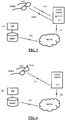
Figures 1-4 illustrate embodiments of the invention, wherein the visualization parameter data VPD are stored in a memory on the device HMD: -
Figures 1-2 illustrate embodiments wherein computer-generated image data ID or HD are provided on a communication terminal COM TERM. -
Figures 3-4 illustrate embodiments wherein computer-generated image data ID or HD are provided on a communication server COM SERV connected to a communication database DB. - The arrows indicate steps of providing data with annotation of the respective data transmitted, and the stars (*) indicate that the calculation step, namely step (iii), can be performed by a processor either on the terminal TERM or on the device HMD.
- In another aspect of the invention, the visualization parameter data VPD of step (i) may be stored in a memory stored in a wearer database WEAR DB on a communication server COM SERV connected to said communication terminal COM TERM via a communication network COM NETW, in association with a visualization parameter identifier VP ID. This identifier VP ID can be defined as an identifier that allows the retrieval of said visualization parameter data (VPD). For example, it allows the retrieval of OD or HMDD data. This embodiment is advantageous in that it allows updates of the visualization parameter data VPD. For example, for a given wearer, prescription data may evolve over time and/or the wearer may change device HMD. The use of a server in the method provides for update features to faithfully customize image displays by the device HMD. The visualization parameter identifier VP ID can be an individual one, for example, a unique identifier that identifies a given wearer. The visualization parameter identifier VP ID may also be a generic identifier (group identifier), for example to identify a group of wearer having identical prescription data PD, for example wearers having the same myopia correction, or a group of wearer having the same model of device HMD. The visualization parameter identifier VP ID may be a code, such as a QR code or an RFID code, located on the HMD. It may also be a modulation frequency specific to the HMD (and the wearer). It may be an optical signature.
- Where the visualization parameter data VPD are stored in a database DB on a server SERV, the retrieval of the visualization parameter data VPD can be performed by transmitting the visualization parameter data VPD from the database DB to a terminal TERM, and then optionally from said terminal TERM to the device HMD. Accordingly, step (i) may comprise (i-a) a step of detecting, by said communication terminal COM TERM, the presence of said wearer, and (i-b) responsive to the detected presence at step (i-a), a step of transmitting said visualization parameter data VPD from said communication server COM SERV to said communication terminal COM TERM. Step (i) may then optionally comprise (i-c) a further step of transmitting visualization parameter data VPD from said communication terminal COM TERM to said device HMD. The update of visualization parameter data VPD may be performed via a computer at an eye specialist shop, or by the wearer through a computer, a tablet or a smartphone.
- Where the visualization parameter data VPD are stored in a database DB on a server SERV, step (iii) of calculating modified image data MID may be performed either by a processor located on a terminal TERM or by a processor located in a server SERV. Accordingly, wherein step (iii) may comprise a step of transmitting modified computer-generated image data MID from said communication terminal COM TERM to said device HMD, and optionally, a prior step of transmitting modified computer-generated image data MID from said communication server COM SERV to said communication terminal COM TERM.
-
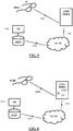
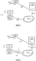
Figures 5-8 illustrate embodiments of the invention, wherein the visualization parameter data VPD are stored in a database: -
Figure 5 illustrates an embodiment wherein visualization parameter data VPD are retrieved from a communication database DB and transmitted to the device HMD via a communication terminal COM TERM. -
Figure 6 illustrates an embodiment wherein computer-generated image data ID, HD are provided on a communication terminal COM TERM. -
Figures 7 and 8 illustrate embodiments wherein computer-generated image data ID, HD are provided on a communication server SERV connected to a communication database DB. - The arrows indicate steps of providing data, and the stars (*) indicate that the calculation step, namely step (iii), can be performed by a processor on the terminal TERM, on the server SERV or on the device HMD.
- According to the invention, where image data are stored in an image database IM DB on a server SERV, it is possible to define access rights to certain images. Accordingly, where said computer-generated image data ID or said modified computer-generated image data MID are stored in an image database IM DB, the method of the invention may comprise a preliminary step of pre-registering, in said database, an association between a wearer identifier WEAR ID and said wearer, and the computer-generated image data ID of step (ii) and/or the modified computer-generated image data MID of step (iii) are determined (defined) according to said wearer identifier WEAR ID, optionally in accordance with access rights. The wearer identifier thus allows the definition of the wearer profile. The wearer identifier WEAR ID may be the same or different than the visualization parameter identifier VP ID. The wearer identifier may be a code, for example a QR code or an RFID code, located on the device HMD. It is thus possible to define one or more levels of access rights in connection with the image database IM DB.
- Another aspect provides systems, including lighting terminals LIGHT TERM and devices HMD. Said systems are suitable (arranged, configured) for performing the method of the invention.
- An aspect thus relates to a lighting terminal LIGHT TERM. This terminal is suitable (arranged, configured) for the implementation of the method of the invention, in particular where the computer-generated image is a holographic image.
- The light terminal LIGHT TERM comprises:
- a light source LIGHT SOURC suitable (arranged, configured) for displaying a holographic image by illumination,
- optionally, a sensor SENS suitable (arranged, configured) for detecting the presence of a wearer provided with a head-mounted computer-generated holographic image displaying device HMD, and
- optionally, a communication interface INT suitable (arranged, configured) for transmitting, from and/or to said terminal, data selected from visualization parameter data VPD, computer-generated holographic image data HD and modified computer-generated holographic image data MHD..
- The communication interface INT may include a USB port and/or any other interface for wireless communication, including radiofrequency such as Bluetooth, Wi-Fi, 4G, 3G; optical (Li-Fi or FSO) and/or IR communication; and/or a photodiode (for receiving data) and/or an emitter, for example a visible or near IR light source (for emitting data). Further, the light terminal LIGHT TERM may comprise one or more of the following:
- a battery or any other power means,
- a GPS for determining GPS coordinates,
- one memory or a plurality of memories,
- a digital camera,
- other sensors,
- a controller CONT suitable (arranged, configured) for processing holographic image data (modified or not). Said controller CONT is suitable (arranged, configured) for performing step (iii) and comprises a processor.
- In a preferred embodiment, in the lighting terminal LIGHT TERM of the invention, said light source LIGHT SOURC is further suitable (arranged, configured) for transmitting computer-generated holographic image data HD and/or modified computer-generated holographic image data MHD from said lighting terminal LIGHT TERM.
- This dual role (illumination for display and data transmission) is particularly advantageous, in that it provides for image display on HMD devices, even if said HMD devices do not comprise their own light source. Further, it relies on a dual role of a terminal that can transmit data including image data and, advantageously immediately thereafter, can cause display of the image by providing an illumination with a light beam suitable (arranged, configured).
- An aspect also pertains to a deployed network of lighting terminals as described herein. It thus relates to a system comprising a plurality of lighting terminals LIGHT TERM as described herein, wherein each of said lighting terminals LIGHT TERM is connected to a lighting server LIGHT SERV via a lighting network LIGHT NETW. Servers and networks are known in the art. For example, for communication purposes, it is possible to connect a plurality of terminals with a server via a network. Similarly, where the terminals are lighting terminals, each of said lighting terminals LIGHT TERM may be arranged (configured) to be in communication (connected) with a server LIGHT SERV via a network LIGHT NETW. According to the invention, a lighting terminal may also be a communication terminal. Further, a plurality of said lighting/communication terminals TERM may be arranged (configured) to be in communication (connected) with a server SERV via a network NETW.
- In another aspect, the invention pertains to a head-mounted device. The invention provides a head-mounted computer-generated image displaying device HMD, comprising:
- a phase and/or amplitude spatial light modulator SLM, and
- optionally, a light source LIGHT SOURC suitable (arranged, configured) for displaying an image illumination, and
- optionally, a communication interface µINT suitable (arranged, configured) for transmitting, from and/or to said device HMD, data selected from visualization parameter data VPD, computer-generated image data ID and modified computer-generated image data MID,
- This device HMD is suitable (arranged, configured) for implementing the method of the present invention.
- In a preferred embodiment, said device HMD is a pair of prescription eyeglasses with a phase SLM.
- Preferably, the computer-generated image is a computer-generated holographic image.
- The SLM is preferably a phase SLM, for example phase-only, and can be made of LCoS; or Glass transmissive Active Matrix Liquid Crystal. The SLM may also be a "see-through" SLM provided before the wearer eye, in which case no holographic mirror is required. When the SLM is provided elsewhere than before the wearer eye, for example when the SLM is provided on the side of the device HMD or near the wearer temple, then a holographic mirror may be required.
- According to the invention, the device HMD may comprise one or more of the following:
- at least one lens, wherein said lens is provided with an anti-reflection coating and optionally a holographic mirror provided on or within the lens on the side of the wearer; the holographic mirror is preferably present when the device HMD is provided with a built-in light source LIGHT SOURC,
- the lens may be part of a pair of prescription lenses,
- a battery,
- a GPS,
- at least one memory,
- a camera,
- a microphone,
- sensors, for example an eye tracker, a movement tracker or haptic means, including haptic command means,
- a micro-controller (µCONT) suitable (arranged, configured) for processing (decoding, demodulating, coding, etc.) image data. Said controller CONT may be suitable (arranged, configured) for performing step (iii) and comprise a processor.
- The communication interface µINT may include a USB port and/or any other interface for wireless communication, including radiofrequency such as Bluetooth, Wi-Fi, 4G, 3G; optical (Li-Fi or FSO) and/or IR communication; and/or a photodiode (for receiving data) and/or an emitter, for example a visible or near IR light source (for emitting data). The device HMD may comprise a memory suitable (arranged, configured) for storing data selected from visualization parameter data VPD, computer-generated image data ID and modified computer-generated image data MID. The programming of the device HMD may include inputting data selected from visualization parameter data VPD, computer-generated image data ID and modified computer-generated image data MID. Examples of devices HMD are illustrated on
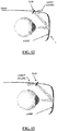
Figures 12-14 . These examples are devices comprising a light source LIGHT SOURC mounted on a temple TEMP of the device, although the presence of said light source LIGHT SOURC is optional. - The device HMD comprises a spatial light modulator SLM and a lens L.
- The SLM may be located on a temple TEMP of the device HMD. The SLM may function in reflection (
Figure 12 ) or in transmission (Figures 13 ). The light beam emitted by the light source LIGHT SOURC is respectively reflected (Figure 12 ) or transmitted (Figure 13 ) by the SLM, before hitting the lens L. Where the device HMD comprises a reflective SLM, the device HMD further comprises a holographic mirror. The lens L is provided with a holographic mirror MIRR on the side of the lens L facing the eye of the wearer. The lens L is also provided with an anti-reflection coating. After reflection on the holographic mirror MIRR, the light beam is directed to the wearer eye, thus causing visualization of the holographic image. The holographic mirror MIRR is off-center. - Holographic mirrors are known in the art, part of optical holography elements. They can for example comprise a diffraction grating of set fringes. The holographic mirror may be made of photopolymers of dichromated gelatins or synthetic photopolymer known in the art or bleached silver holographic emulsions. Advantageously, the holographic mirror MIRR can be combined with the lens without affecting the geometry of the lens. As a consequence, the optical function of the lens and the optical function of the holographic mirror are completely de-correlated and can be optimized independently. The holographic mirror may be designed so as to correct for some or all of the optical aberrations of the system (notably since the SLM is located on a glass temple TEMP as on
Figures 12-13 , it is off-center, which gives rise to optical aberrations in the image as visualized by the wearer). The holographic mirror may be manufactured angular fraction by angular fraction so as to limit field aberrations (reduced aperture). In such case, the mirror reflects the light in the desired wavelength(s) only for the incident light in a given direction. Such mirrors are especially advantageous for devices HMD provided with a built-in light source LIGHT SOURC. For constructing an image with larger aperture, it is possible to fragment the overall image and proceed with a scanning of the mirror by the beam. - The SLM may also be a "see-through" transmissive SLM as shown on
Figure 14 . A remote light source LIGHT SOURC emits a beam that is transmitted through the lens L and the SLM to reach the wearer's eye. - For monochromatic use, the holographic mirror is optically recorded (defined) at the wavelength of illumination. For wavelength other than this wavelength, the mirror is transparent and thus does not impair vision by the wearer through the lens. For tri-chromatic use (red, green, blue), the holographic mirror is optically recorded (defined) at three wavelengths and the holographic image can be visualized in the three wavelengths considered. The holographic mirror is transparent at the other wavelengths. Similarly, for wavelengths other than the three selected wavelengths, the mirror is transparent and thus does not impair vision by the wearer through the lens (diffraction efficacy is nil). Preferably, the mirror is optically recorded for various angles of illumination (incident light). More generally, the design and setup of the holographic mirror is common knowledge for the skilled person.
- The devices HMD of the invention are advantageous in that they protect confidentiality of the images visualized by the wearer wearing the device HMD, because the mirror is specific to the wavelength(s) used for illumination and visualization.
- When the SLM is provided on a temple of the glasses/HMD, it is obviously off-center, and thus the projection of the holographic image by the SLM creates visual/optical aberrations, which can advantageously be at least partially compensated by a suitable modification of the holographic image data. The SLM thus modifies the wave front emitted (transmitted or reflected) by the SLM accordingly, leading to improved visual experience and comfort.
- The present invention also pertains to the use of an SLM in a head-mounted device. More particularly, the invention pertains to the use of an SLM in eyeglasses, including prescription eyeglasses. The SLM can be a phase and/or amplitude spatial light modulator SLM, preferably a phase or phase-only SLM, for example an LCoS SLM or a Glass transmissive Active Matrix LC SLM.
- A myopic wearer is equipped with a device HMD of the invention. The wearer is allocated visualization parameter data VPD comprising prescription data PD (power for left and right eye) and device data HMDD corresponding to said device HMD. The visualization parameter data VPD are stored on a memory on said device HMD.
- In one embodiment, the method of the invention can be implemented as follows, as illustrated at
Figure 1 . A metro station is provided with a stand-alone terminal TERM comprising a light source LIGHT SOURC, a memory and a processor. Computer-generated holographic image data HD representing the map of a metro line are stored in the memory of the terminal TERM. The terminal TERM detects the presence of the wearer wearing the device HMD. This causes the transmission of the visualization parameter data VPD from the device HMD to the terminal TERM. The processor of the terminal performs a calculation step so as to provide modified holographic image data MHD, which are adapted to the wearer prescription data PD and to the device design HMDD. Said modified data MHD are then transmitted from the terminal TERM to the device HMD using Li-Fi communication. - In another embodiment, the method of the invention can be implemented as follows, as illustrated at
Figure 2 . A metro station is provided with a stand-alone terminal TERM comprising a light source LIGHT SOURC, a memory and a processor. Computer-generated holographic image data HD representing the map of a metro line are stored in the memory of the terminal TERM. The terminal TERM detects the presence of the wearer wearing the device HMD. This causes the transmission of the holographic image data HD from the terminal TERM to the device HMD by Li-Fi. The device HMD is equipped with a processor which performs a calculation step so as to provide modified holographic image data MHD, which are adapted to the wearer prescription data PD and to the device design HMDD. - In both embodiments, the light source LIGHT SOURC of the terminal TERM emits a light beam suitable (arranged, configured) for causing the display of the modified holographic image of the metro line map, thus allowing the wearer to find orientation in the metro.
- The wearer experiences augmented reality with personalized feature, since the display provides for correction of the holographic image as a function of the wearer prescription data.
- An astigmatic wearer is equipped with a device HMD. The wearer has visualization parameter data VPD comprising prescription data PD (astigmatism modulus and axis for left and right eye) and device data HMDD corresponding to said device. The device HMD comprises a clock, a memory and a built-in light source LIGHT SOURC. The clock is suitable for providing date and time. The memory comprises modified holographic image data that take into account the wearer's astigmatism prescription data PD and device data HMDD. The holographic image data comprise
digits
dd/mm/yy (day/month/year)
hh:mm (hours:minutes) - The HMD allows for the customization of the size of the fonts, of the location of the display (for example on the right-hand lower corner of the vision field), and of other display formats, such as
hh : mm (am or pm) (hours:minutes). - Alternatively, the holographic image data may be those for the image of an actual clock with hands. The display of time and/or date is advantageously customized to the wearer, and provides for prescription-compliant display of time using personalized computer-generated holographic images. This example may be generalized to further embodiments where no terminal is required for performing the method.
- A presbyopic wearer is equipped with a device HMD. The wearer has visualization parameter data VPD comprising prescription data PD (left and right eye) and device data HMDD corresponding to said device. The device comprises a light source LIGHT SOURC.
- The wearer is provided with a terminal TERM in the form of a tablet. The tablet is suitable (arranged, configured) for transmitting data to the device HMD. The tablet can be connected to the Internet and for example to a cloud via Wi-Fi communication.
- In one embodiment, the visualization parameter data VPD are stored on a memory on the HMD. The tablet can transmit to the device HMD a set of holographic image data HD representing the timetable of the wearer's day. The tablet detects the presence of the wearer, which causes the transmission of the data HD to the device HMD. The data HD are subsequently stored on the memory of the device (uploaded from the tablet) as such, can be modified by taking into account visualization data VPD, and may be also stored therein once modified to take into account the visualization data VPD.
- Alternatively, in another embodiment, the tablet may comprise a memory storing the visualization parameter data VPD, and the tablet may be programmed to directly calculate and transmit modified data MHD instead of unmodified holographic image data HD to the device HMD.
- For both embodiments, for the rest of the day, even when the wearer is 'off line', namely even if the HMD is not connected to a terminal or to a server, the wearer may access and display, as a holographic image, the time table data upon demand, for example following a haptic command. The display is possible upon illumination by the light source of the HMD. The display is advantageously customized to the presbyopia of the wearer. Updates of the data for the timetable are possible by connection to a suitable (arranged, configured) terminal connected to the relevant server or cloud.
- Possible applications are in a museum, wherein a single light source LIGHT SOURC is part of a terminal TERM and may emit for the benefit of a wearer visiting the museum. Further, the light source LIGHT SOURC may emit in multiplex mode, so that it may be used for the benefit of a plurality of HMD wearers visiting the museum at the same time.
- A terminal TERM equipped with a light source LIGHT SOURC may be set in a vehicle such as a car, motorbike, plane, truck. The terminal is for the display of information such as information about traffic, weather, etc. The information is displayed in a discrete, yet very visible fashion (as opposed to roads signs not always very visible by night or under difficult weather conditions such as rain or fog). The image is 'set' in the reference system of the vehicle, so that the driver needs not turn the head to watch for signs. Further, the light source may emit in multiplex mode and display other information for the benefit of another non-driving person in the vehicle.
- Building security (control of ins/outs) can be performed according to the invention. A terminal at the entrance allows the display of a virtual keyboard for entering an entrance code. Entering the building requires visitors to wear a suitable (arranged, configured) HMD.
Claims (15)
- Computer-implemented method for the processing of computer-generated holographic image data (HD) for display with a head-mounted computer-generated holographic image displaying device (HMD) worn by a wearer, comprising:(i) a step of providing visualization parameter data (VPD) selected from- wearer ophthalmic data (OD) including wearer prescription data (PD), wearer eye sensitivity data (SD) and wearer ophthalmic biometry data (BD); and- head-mounted device data (HMDD) including frame data (FD) and lens data (LD),(ii) a step of providing computer-generated holographic image data (HD),(iii) a step of calculating modified computer-generated holographic image data (MHD) from the computer-generated holographic image data (HD) of step (ii) by taking into account the visualization parameter data (VPD) of step (i),(iv) a step of providing the modified computer-generated holographic image data (MHD) of step (iii) to said device (HMD) for display, and(v) a step of emitting, by at least one light source (LIGHT SOURC) provided on a remote lighting terminal, a light beam arranged for displaying the holographic image from the modified computer-generated holographic image data (MHD) of step (iii) by illumination of said device (HMD),wherein said at least one light source (LIGHT SOURC) is further arranged to transmit data, and wherein:- step (ii) comprises a step of transmitting said computer-generated holographic image data (HD) from said at least one light source (LIGHT SOURC) to said device (HMD), or- step (iv) comprises a step of transmitting said modified computer-generated holographic image data (MHD) from said at least one light source (LIGHT SOURC) to said device (HMD).
- Computer-implemented method of claim 1, wherein said visualization parameter data (VPD) are wearer prescription data (PD) selected from astigmatism module, astigmatism axis, power, prism and addition.
- Computer-implemented method of claim 1 or 2, wherein at least one of said visualization parameter data (VPD) of step (i) are stored in a memory on said device (HMD).
- Computer-implemented method of claim 3, wherein step (i) comprises:(i-a) a step of detecting, by at least one communication terminal (COM TERM), the presence of said wearer,(i-b) responsive to the detected presence at step (i-a), a step of transmitting said visualization parameter data (VPD) from said device (HMD) to said communication terminal (COM TERM),and wherein step (iv) comprises a step of transmitting modified computer-generated holographic image data (MHD) from said communication terminal (COM TERM) to said device (HMD).
- Computer-implemented method of claim 1 or 2, wherein at least one of said visualization parameter data (VPD) of step (i) are stored in a wearer database (WEAR DB) on a communication server (COM SERV) connected to at least one communication terminal (COM TERM) via a communication network (COM NETW), in association with a visualization parameter identifier (VP ID) which is an identifier that allows the retrieval of said visualization parameter data (VPD).
- Computer-implemented method of claim 5, wherein step (i) comprises:(i-a) a step of detecting, by said at least one communication terminal (COM TERM), the presence of said wearer,(i-b) responsive to the detected presence at step (i-a), a step of transmitting said visualization parameter data (VPD) from said communication server (COM SERV) to said communication terminal (COM TERM).
- Computer-implemented method of claim 6, wherein step (i) comprises:
(i-c) a further step of transmitting visualization parameter data (VPD) from said communication terminal (COM TERM) to said device (HMD). - Computer-implemented method of claim 5, wherein step (iv) comprises:- a step of transmitting modified computer-generated holographic image data (MHD) from said communication terminal (COM TERM) to said device (HMD).
- Computer-implemented method of claim 8, wherein step (iv) comprises:- a prior step of transmitting modified computer-generated holographic image data (MHD) from said communication server (COM SERV) to said communication terminal (COM TERM).
- Computer-implemented method of any of claims 1-9, wherein said computer-generated holographic image data (HD) or said modified computer-generated holographic image data (MHD) are stored in an image database (IM DB),
wherein said method comprises a preliminary step of pre-registering, in said database, an association between a wearer identifier (WEAR ID) and said wearer, and
wherein said computer-generated holographic image data (HD) of step (ii) and/or said modified computer-generated holographic image data (MHD) of step (iii) are defined according to said wearer identifier (WEAR ID). - Computer-implemented method of claim 10, wherein said computer-generated holographic image data (HD) of step (ii) and/or said modified computer-generated holographic image data (MHD) of step (iii) are defined according to said wearer identifier (WEAR ID) in accordance with access rights.
- System for displaying a computer-generated holographic image for a wearer of a head-mounted computer-generated holographic image displaying device (HMD), the system comprising:- said head-mounted displaying device (HMD), and- at least one lighting terminal communicating with said device (HMD) and comprising:
* a light source (LIGHT SOURC), and- * a sensor (SENS) arranged for detecting the presence of a wearer provided with said device (HMD), and/or a communication interface (INT) arranged for transmitting, from and/or to said terminal, data selected from visualization parameter data (VPD), computer-generated holographic image data (HD) and modified computer-generated holographic image data (MHD),wherein said light source (LIGHT SOURC) is arranged for transmitting computer-generated holographic image data (HD) and/or modified computer-generated holographic image data (MHD) from said lighting terminal, and for emitting a light beam to illuminate said device (HMD) so as to display the holographic image
and wherein the system is arranged to implement the method of claim 1. - System according to claim 12, wherein it comprises a plurality of said lighting terminals, each of which is connected to a lighting server via a lighting network.
- System according to claim 12 or 13, wherein said head-mounted computer-generated holographic image displaying device (HMD) comprises a phase and/or amplitude spatial light modulator (SLM), for example made of LCoS (liquid crystal on silicon) or Glass transmissive Active Matrix Liquid Crystal.
- System according to claim 14, wherein said head-mounted computer-generated holographic image displaying device (HMD) is wearer-prescription-compliant, being arranged for correcting ametropia via said phase and/or amplitude spatial light modulator (SLM).
Priority Applications (1)
| Application Number | Priority Date | Filing Date | Title |
|---|---|---|---|
| EP14758926.1A EP3042249B1 (en) | 2013-09-04 | 2014-09-03 | Methods and systems for augmented reality |
Applications Claiming Priority (3)
| Application Number | Priority Date | Filing Date | Title |
|---|---|---|---|
| EP13306208 | 2013-09-04 | ||
| EP14758926.1A EP3042249B1 (en) | 2013-09-04 | 2014-09-03 | Methods and systems for augmented reality |
| PCT/EP2014/068758 WO2015032828A1 (en) | 2013-09-04 | 2014-09-03 | Methods and systems for augmented reality |
Publications (2)
| Publication Number | Publication Date |
|---|---|
| EP3042249A1 EP3042249A1 (en) | 2016-07-13 |
| EP3042249B1 true EP3042249B1 (en) | 2020-03-18 |
Family
ID=49170647
Family Applications (1)
| Application Number | Title | Priority Date | Filing Date |
|---|---|---|---|
| EP14758926.1A Active EP3042249B1 (en) | 2013-09-04 | 2014-09-03 | Methods and systems for augmented reality |
Country Status (6)
| Country | Link |
|---|---|
| US (1) | US10520730B2 (en) |
| EP (1) | EP3042249B1 (en) |
| JP (1) | JP6675312B2 (en) |
| KR (1) | KR102309257B1 (en) |
| CN (1) | CN105518539A (en) |
| WO (1) | WO2015032828A1 (en) |
Families Citing this family (50)
| Publication number | Priority date | Publication date | Assignee | Title |
|---|---|---|---|---|
| US10048647B2 (en) | 2014-03-27 | 2018-08-14 | Microsoft Technology Licensing, Llc | Optical waveguide including spatially-varying volume hologram |
| US10062224B2 (en) * | 2014-05-20 | 2018-08-28 | Tyco Safety Products Canada Ltd. | Dual access level security system and method |
| NZ773815A (en) | 2015-03-16 | 2022-07-01 | Magic Leap Inc | Methods and systems for diagnosing and treating health ailments |
| JP6966325B2 (en) * | 2015-04-03 | 2021-11-17 | エシロール アンテルナショナルEssilor International | Methods and systems for augmented reality |
| US9939644B2 (en) * | 2015-06-25 | 2018-04-10 | Intel Corporation | Technologies for controlling vision correction of a wearable computing device |
| US10210844B2 (en) | 2015-06-29 | 2019-02-19 | Microsoft Technology Licensing, Llc | Holographic near-eye display |
| US9798894B2 (en) * | 2015-07-02 | 2017-10-24 | Xerox Corporation | Secure computer display using inverse computational light field displays |
| CN107924057B (en) | 2015-07-03 | 2020-12-22 | 依视路国际公司 | Method and system for augmented reality |
| US10416456B2 (en) | 2015-07-03 | 2019-09-17 | Essilor International | Methods and systems for augmented reality |
| US20180224673A1 (en) * | 2015-09-16 | 2018-08-09 | Robert Therrien | Relaxation and meditation eyewear |
| DE102015219859B4 (en) | 2015-10-13 | 2017-07-27 | Carl Zeiss Vision International Gmbh | Apparatus and method for AR display |
| US10338410B1 (en) * | 2015-12-28 | 2019-07-02 | Facebook Technologies, Llc | Eyeglass prescription correction for optics blocks in head-mounted displays |
| US11663937B2 (en) | 2016-02-22 | 2023-05-30 | Real View Imaging Ltd. | Pupil tracking in an image display system |
| WO2017145158A1 (en) | 2016-02-22 | 2017-08-31 | Real View Imaging Ltd. | Zero order blocking and diverging for holographic imaging |
| WO2017145154A1 (en) | 2016-02-22 | 2017-08-31 | Real View Imaging Ltd. | Wide field of view hybrid holographic display |
| EP3420413A1 (en) | 2016-02-22 | 2019-01-02 | Real View Imaging Ltd. | A method and system for displaying holographic images within a real object |
| EP3329316B1 (en) * | 2016-03-11 | 2023-09-20 | Facebook Technologies, LLC | Corneal sphere tracking for generating an eye model |
| US10115205B2 (en) | 2016-03-11 | 2018-10-30 | Facebook Technologies, Llc | Eye tracking system with single point calibration |
| JP6409015B2 (en) * | 2016-03-29 | 2018-10-17 | 矢崎総業株式会社 | Projection display device for vehicle |
| IL299497B2 (en) | 2016-04-08 | 2024-02-01 | Magic Leap Inc | Augmented reality systems and methods with variable focus lens elements |
| US20170323482A1 (en) * | 2016-05-05 | 2017-11-09 | Universal City Studios Llc | Systems and methods for generating stereoscopic, augmented, and virtual reality images |
| US10108144B2 (en) | 2016-09-16 | 2018-10-23 | Microsoft Technology Licensing, Llc | Holographic wide field of view display |
| EP3296793A1 (en) * | 2016-09-19 | 2018-03-21 | Essilor International | Method of determining a correcting optical function to a virtual image |
| EP3296792A1 (en) * | 2016-09-19 | 2018-03-21 | Essilor International | Method for managing the display of an image to a user of an optical system |
| US10254542B2 (en) | 2016-11-01 | 2019-04-09 | Microsoft Technology Licensing, Llc | Holographic projector for a waveguide display |
| US20180144554A1 (en) | 2016-11-18 | 2018-05-24 | Eyedaptic, LLC | Systems for augmented reality visual aids and tools |
| US11022939B2 (en) | 2017-01-03 | 2021-06-01 | Microsoft Technology Licensing, Llc | Reduced bandwidth holographic near-eye display |
| KR102601052B1 (en) | 2017-02-23 | 2023-11-09 | 매직 립, 인코포레이티드 | Display system with variable power reflector |
| JP7058471B2 (en) * | 2017-04-17 | 2022-04-22 | キヤノン株式会社 | Image processing device, image processing method |
| JP6994048B2 (en) * | 2017-05-17 | 2022-01-14 | アップル インコーポレイテッド | Head mount display device for vision correction |
| US10712567B2 (en) | 2017-06-15 | 2020-07-14 | Microsoft Technology Licensing, Llc | Holographic display system |
| US20190012841A1 (en) | 2017-07-09 | 2019-01-10 | Eyedaptic, Inc. | Artificial intelligence enhanced system for adaptive control driven ar/vr visual aids |
| CN107589562A (en) * | 2017-09-20 | 2018-01-16 | 厦门云镜视界设计有限公司 | A kind of making spectacles to order method |
| IL307639A (en) * | 2017-09-27 | 2023-12-01 | Magic Leap Inc | Near eye 3d display with separate phase and amplitude modulators |
| US10984508B2 (en) * | 2017-10-31 | 2021-04-20 | Eyedaptic, Inc. | Demonstration devices and methods for enhancement for low vision users and systems improvements |
| EP3502763B1 (en) | 2017-12-22 | 2023-02-01 | Essilor International | Head mounted device comprising a fourier hologram |
| JP2020507094A (en) * | 2017-12-25 | 2020-03-05 | 歌爾科技有限公司GoerTek Technology Co., Ltd. | Laser beam scanning display device and augmented reality glasses |
| US11614623B2 (en) | 2018-02-26 | 2023-03-28 | Veyezer, Llc | Holographic real space refractive system |
| US11253149B2 (en) | 2018-02-26 | 2022-02-22 | Veyezer, Llc | Holographic real space refractive sequence |
| US10441161B2 (en) * | 2018-02-26 | 2019-10-15 | Veyezer LLC | Holographic real space refractive sequence |
| US11563885B2 (en) | 2018-03-06 | 2023-01-24 | Eyedaptic, Inc. | Adaptive system for autonomous machine learning and control in wearable augmented reality and virtual reality visual aids |
| EP3567419A1 (en) * | 2018-05-11 | 2019-11-13 | Essilor International (Compagnie Generale D'optique) | A system for generating a virtual image for a wearer |
| US11187906B2 (en) | 2018-05-29 | 2021-11-30 | Eyedaptic, Inc. | Hybrid see through augmented reality systems and methods for low vision users |
| EP3856098A4 (en) | 2018-09-24 | 2022-05-25 | Eyedaptic, Inc. | Enhanced autonomous hands-free control in electronic visual aids |
| DE102018126329A1 (en) * | 2018-10-23 | 2020-04-23 | Valeo Schalter Und Sensoren Gmbh | Method for aligning a virtual image element and head-up display for imaging a virtual image element |
| US10930183B2 (en) * | 2018-11-22 | 2021-02-23 | Electronics And Telecommunications Research Institute | Hologram content generation apparatus, integrated hologram content control system having the same, and method for operating the hologram content generation apparatus |
| CN109769136B (en) * | 2018-12-07 | 2021-02-19 | 北京交通大学 | Online video cache management method and system based on instantaneous access rate value |
| CA3134734A1 (en) * | 2019-05-09 | 2020-11-12 | Evolution Optiks Limited | Corrective light field display profile management, communication and integration system and method |
| US20220343606A1 (en) * | 2021-04-21 | 2022-10-27 | NewSight Reality, Inc. | Optical module with active microlens array capable of synchronizing with see-through display to provide multiple modes of functionality |
| US11790345B2 (en) * | 2022-02-03 | 2023-10-17 | Bank Of America Corporation | Card to card transaction initiation using light fidelity (“LIFI”) enabled smart glasses |
Family Cites Families (24)
| Publication number | Priority date | Publication date | Assignee | Title |
|---|---|---|---|---|
| US6421147B2 (en) * | 1998-07-07 | 2002-07-16 | Denso Corporation | Hologram screen and a method of producing the same |
| JP3385238B2 (en) * | 1999-01-12 | 2003-03-10 | シャープ株式会社 | Optical transceiver module |
| JP3827082B2 (en) * | 2002-10-24 | 2006-09-27 | 株式会社中川研究所 | Broadcast system, light bulb, lighting device |
| US7733298B2 (en) * | 2004-10-19 | 2010-06-08 | Hewlett-Packard Development Company, L.P. | Display device |
| JP2006208687A (en) * | 2005-01-27 | 2006-08-10 | Konica Minolta Photo Imaging Inc | Video control system for head-mounted display |
| DE102006003741B4 (en) * | 2006-01-18 | 2009-08-27 | Seereal Technologies S.A. | Method for coding a computer-generated hologram |
| JP2007274566A (en) * | 2006-03-31 | 2007-10-18 | Nakagawa Kenkyusho:Kk | Illumination light communication device |
| FR2900475B1 (en) * | 2006-04-26 | 2008-10-31 | Essilor Int | DISPLAY COMPRISING A PAIR OF BINOCULAR GLASSES AND WITH A DEVICE FOR ADJUSTING THE IMAGE |
| US7595933B2 (en) * | 2006-10-13 | 2009-09-29 | Apple Inc. | Head mounted display system |
| JP4963467B2 (en) * | 2007-12-14 | 2012-06-27 | 独立行政法人情報通信研究機構 | Hologram pattern generator, electronic holography astigmatism correction method, and hologram pattern generation program |
| US8019233B2 (en) * | 2008-05-30 | 2011-09-13 | Avago Technologies Fiber Ip (Singapore) Pte. Ltd. | Method and apparatus for using a hologram to control the optical field distribution of light generated by a light source and launched into an end of an optical waveguide |
| JP4858512B2 (en) * | 2008-08-21 | 2012-01-18 | ソニー株式会社 | Head-mounted display |
| US8436789B2 (en) * | 2009-01-16 | 2013-05-07 | Microsoft Corporation | Surface puck |
| JP5874176B2 (en) * | 2011-03-06 | 2016-03-02 | ソニー株式会社 | Display device and relay device |
| JP5451670B2 (en) * | 2011-03-15 | 2014-03-26 | 株式会社アウトスタンディングテクノロジー | Visible light communication device |
| JP5118266B2 (en) * | 2011-03-25 | 2013-01-16 | パナソニック株式会社 | Display device |
| US9389421B2 (en) * | 2011-10-20 | 2016-07-12 | Panasonic Intellectual Property Management Co., Ltd. | Display device and display system |
| US9143402B2 (en) * | 2012-02-24 | 2015-09-22 | Qualcomm Incorporated | Sensor based configuration and control of network devices |
| JP5994715B2 (en) * | 2012-04-10 | 2016-09-21 | パナソニックIpマネジメント株式会社 | Computer generated hologram display |
| CN102857299A (en) * | 2012-08-23 | 2013-01-02 | 中国科学院苏州纳米技术与纳米仿生研究所 | Optical communication system and method |
| CA3140855A1 (en) * | 2012-12-31 | 2014-07-03 | Esight Corporation | Apparatus and method for fitting head mounted vision augmentation systems |
| EP2973432A4 (en) * | 2013-03-15 | 2016-08-31 | Huntington Ingalls Inc | Method and system for disambiguation of augmented reality tracking databases |
| CN103297888A (en) * | 2013-04-24 | 2013-09-11 | 青岛海信电器股份有限公司 | Wireless headset device, mobile terminal device and light source device capable of being modulated |
| EP3042248B1 (en) * | 2013-09-04 | 2020-06-17 | Essilor International | Methods and systems for augmented reality |
-
2014
- 2014-09-03 KR KR1020167005451A patent/KR102309257B1/en active IP Right Grant
- 2014-09-03 JP JP2016539532A patent/JP6675312B2/en active Active
- 2014-09-03 CN CN201480048719.0A patent/CN105518539A/en active Pending
- 2014-09-03 EP EP14758926.1A patent/EP3042249B1/en active Active
- 2014-09-03 US US14/916,905 patent/US10520730B2/en active Active
- 2014-09-03 WO PCT/EP2014/068758 patent/WO2015032828A1/en active Application Filing
Non-Patent Citations (1)
| Title |
|---|
| None * |
Also Published As
| Publication number | Publication date |
|---|---|
| KR20160048800A (en) | 2016-05-04 |
| JP2016535872A (en) | 2016-11-17 |
| WO2015032828A1 (en) | 2015-03-12 |
| CN105518539A (en) | 2016-04-20 |
| US10520730B2 (en) | 2019-12-31 |
| US20160216515A1 (en) | 2016-07-28 |
| EP3042249A1 (en) | 2016-07-13 |
| JP6675312B2 (en) | 2020-04-01 |
| KR102309257B1 (en) | 2021-10-06 |
Similar Documents
| Publication | Publication Date | Title |
|---|---|---|
| EP3042249B1 (en) | Methods and systems for augmented reality | |
| US10698364B2 (en) | Methods and systems for augmented reality | |
| US10884246B2 (en) | Releasably attachable augmented reality system for eyewear | |
| US10466487B2 (en) | Releasably attachable augmented reality system for eyewear | |
| US10534174B2 (en) | Methods and systems for augmented reality | |
| US20180084232A1 (en) | Optical See-Through Head Worn Display | |
| CA2629903C (en) | Ophthalmic lens simulation system and method | |
| US20180003981A1 (en) | Near-to-eye display device with spatial light modulator and pupil tracker | |
| JP6145789B2 (en) | Display device and display system | |
| US10429648B2 (en) | Augmented reality head worn device | |
| US20180003962A1 (en) | Near-to-eye display device with variable resolution | |
| EP3237958A1 (en) | Near-to-eye display device with spatial light modulator and pupil tracker | |
| US10573080B2 (en) | Apparatus and method for augmented reality presentation | |
| WO2021055327A1 (en) | Augmented reality or mixed reality system for eyewear |
Legal Events
| Date | Code | Title | Description |
|---|---|---|---|
| PUAI | Public reference made under article 153(3) epc to a published international application that has entered the european phase |
Free format text: ORIGINAL CODE: 0009012 |
|
| 17P | Request for examination filed |
Effective date: 20160301 |
|
| AK | Designated contracting states |
Kind code of ref document: A1 Designated state(s): AL AT BE BG CH CY CZ DE DK EE ES FI FR GB GR HR HU IE IS IT LI LT LU LV MC MK MT NL NO PL PT RO RS SE SI SK SM TR |
|
| AX | Request for extension of the european patent |
Extension state: BA ME |
|
| DAX | Request for extension of the european patent (deleted) | ||
| RAP1 | Party data changed (applicant data changed or rights of an application transferred) |
Owner name: ESSILOR INTERNATIONAL |
|
| GRAP | Despatch of communication of intention to grant a patent |
Free format text: ORIGINAL CODE: EPIDOSNIGR1 |
|
| STAA | Information on the status of an ep patent application or granted ep patent |
Free format text: STATUS: GRANT OF PATENT IS INTENDED |
|
| INTG | Intention to grant announced |
Effective date: 20191018 |
|
| RIN1 | Information on inventor provided before grant (corrected) |
Inventor name: CANO, JEAN-PAUL Inventor name: LE SAUX, GILLES Inventor name: BOUCHIER, AUDE |
|
| GRAS | Grant fee paid |
Free format text: ORIGINAL CODE: EPIDOSNIGR3 |
|
| GRAA | (expected) grant |
Free format text: ORIGINAL CODE: 0009210 |
|
| STAA | Information on the status of an ep patent application or granted ep patent |
Free format text: STATUS: THE PATENT HAS BEEN GRANTED |
|
| AK | Designated contracting states |
Kind code of ref document: B1 Designated state(s): AL AT BE BG CH CY CZ DE DK EE ES FI FR GB GR HR HU IE IS IT LI LT LU LV MC MK MT NL NO PL PT RO RS SE SI SK SM TR |
|
| REG | Reference to a national code |
Ref country code: GB Ref legal event code: FG4D |
|
| REG | Reference to a national code |
Ref country code: DE Ref legal event code: R096 Ref document number: 602014062527 Country of ref document: DE |
|
| REG | Reference to a national code |
Ref country code: AT Ref legal event code: REF Ref document number: 1246617 Country of ref document: AT Kind code of ref document: T Effective date: 20200415 Ref country code: IE Ref legal event code: FG4D |
|
| PG25 | Lapsed in a contracting state [announced via postgrant information from national office to epo] |
Ref country code: NO Free format text: LAPSE BECAUSE OF FAILURE TO SUBMIT A TRANSLATION OF THE DESCRIPTION OR TO PAY THE FEE WITHIN THE PRESCRIBED TIME-LIMIT Effective date: 20200618 Ref country code: FI Free format text: LAPSE BECAUSE OF FAILURE TO SUBMIT A TRANSLATION OF THE DESCRIPTION OR TO PAY THE FEE WITHIN THE PRESCRIBED TIME-LIMIT Effective date: 20200318 Ref country code: RS Free format text: LAPSE BECAUSE OF FAILURE TO SUBMIT A TRANSLATION OF THE DESCRIPTION OR TO PAY THE FEE WITHIN THE PRESCRIBED TIME-LIMIT Effective date: 20200318 |
|
| REG | Reference to a national code |
Ref country code: NL Ref legal event code: MP Effective date: 20200318 |
|
| PG25 | Lapsed in a contracting state [announced via postgrant information from national office to epo] |
Ref country code: LV Free format text: LAPSE BECAUSE OF FAILURE TO SUBMIT A TRANSLATION OF THE DESCRIPTION OR TO PAY THE FEE WITHIN THE PRESCRIBED TIME-LIMIT Effective date: 20200318 Ref country code: SE Free format text: LAPSE BECAUSE OF FAILURE TO SUBMIT A TRANSLATION OF THE DESCRIPTION OR TO PAY THE FEE WITHIN THE PRESCRIBED TIME-LIMIT Effective date: 20200318 Ref country code: GR Free format text: LAPSE BECAUSE OF FAILURE TO SUBMIT A TRANSLATION OF THE DESCRIPTION OR TO PAY THE FEE WITHIN THE PRESCRIBED TIME-LIMIT Effective date: 20200619 Ref country code: HR Free format text: LAPSE BECAUSE OF FAILURE TO SUBMIT A TRANSLATION OF THE DESCRIPTION OR TO PAY THE FEE WITHIN THE PRESCRIBED TIME-LIMIT Effective date: 20200318 Ref country code: BG Free format text: LAPSE BECAUSE OF FAILURE TO SUBMIT A TRANSLATION OF THE DESCRIPTION OR TO PAY THE FEE WITHIN THE PRESCRIBED TIME-LIMIT Effective date: 20200618 |
|
| REG | Reference to a national code |
Ref country code: LT Ref legal event code: MG4D |
|
| PG25 | Lapsed in a contracting state [announced via postgrant information from national office to epo] |
Ref country code: NL Free format text: LAPSE BECAUSE OF FAILURE TO SUBMIT A TRANSLATION OF THE DESCRIPTION OR TO PAY THE FEE WITHIN THE PRESCRIBED TIME-LIMIT Effective date: 20200318 |
|
| PG25 | Lapsed in a contracting state [announced via postgrant information from national office to epo] |
Ref country code: CZ Free format text: LAPSE BECAUSE OF FAILURE TO SUBMIT A TRANSLATION OF THE DESCRIPTION OR TO PAY THE FEE WITHIN THE PRESCRIBED TIME-LIMIT Effective date: 20200318 Ref country code: IS Free format text: LAPSE BECAUSE OF FAILURE TO SUBMIT A TRANSLATION OF THE DESCRIPTION OR TO PAY THE FEE WITHIN THE PRESCRIBED TIME-LIMIT Effective date: 20200718 Ref country code: RO Free format text: LAPSE BECAUSE OF FAILURE TO SUBMIT A TRANSLATION OF THE DESCRIPTION OR TO PAY THE FEE WITHIN THE PRESCRIBED TIME-LIMIT Effective date: 20200318 Ref country code: LT Free format text: LAPSE BECAUSE OF FAILURE TO SUBMIT A TRANSLATION OF THE DESCRIPTION OR TO PAY THE FEE WITHIN THE PRESCRIBED TIME-LIMIT Effective date: 20200318 Ref country code: PT Free format text: LAPSE BECAUSE OF FAILURE TO SUBMIT A TRANSLATION OF THE DESCRIPTION OR TO PAY THE FEE WITHIN THE PRESCRIBED TIME-LIMIT Effective date: 20200812 Ref country code: SM Free format text: LAPSE BECAUSE OF FAILURE TO SUBMIT A TRANSLATION OF THE DESCRIPTION OR TO PAY THE FEE WITHIN THE PRESCRIBED TIME-LIMIT Effective date: 20200318 Ref country code: EE Free format text: LAPSE BECAUSE OF FAILURE TO SUBMIT A TRANSLATION OF THE DESCRIPTION OR TO PAY THE FEE WITHIN THE PRESCRIBED TIME-LIMIT Effective date: 20200318 Ref country code: SK Free format text: LAPSE BECAUSE OF FAILURE TO SUBMIT A TRANSLATION OF THE DESCRIPTION OR TO PAY THE FEE WITHIN THE PRESCRIBED TIME-LIMIT Effective date: 20200318 |
|
| REG | Reference to a national code |
Ref country code: AT Ref legal event code: MK05 Ref document number: 1246617 Country of ref document: AT Kind code of ref document: T Effective date: 20200318 |
|
| REG | Reference to a national code |
Ref country code: DE Ref legal event code: R097 Ref document number: 602014062527 Country of ref document: DE |
|
| PLBE | No opposition filed within time limit |
Free format text: ORIGINAL CODE: 0009261 |
|
| STAA | Information on the status of an ep patent application or granted ep patent |
Free format text: STATUS: NO OPPOSITION FILED WITHIN TIME LIMIT |
|
| PG25 | Lapsed in a contracting state [announced via postgrant information from national office to epo] |
Ref country code: AT Free format text: LAPSE BECAUSE OF FAILURE TO SUBMIT A TRANSLATION OF THE DESCRIPTION OR TO PAY THE FEE WITHIN THE PRESCRIBED TIME-LIMIT Effective date: 20200318 Ref country code: ES Free format text: LAPSE BECAUSE OF FAILURE TO SUBMIT A TRANSLATION OF THE DESCRIPTION OR TO PAY THE FEE WITHIN THE PRESCRIBED TIME-LIMIT Effective date: 20200318 Ref country code: IT Free format text: LAPSE BECAUSE OF FAILURE TO SUBMIT A TRANSLATION OF THE DESCRIPTION OR TO PAY THE FEE WITHIN THE PRESCRIBED TIME-LIMIT Effective date: 20200318 Ref country code: DK Free format text: LAPSE BECAUSE OF FAILURE TO SUBMIT A TRANSLATION OF THE DESCRIPTION OR TO PAY THE FEE WITHIN THE PRESCRIBED TIME-LIMIT Effective date: 20200318 |
|
| 26N | No opposition filed |
Effective date: 20201221 |
|
| PG25 | Lapsed in a contracting state [announced via postgrant information from national office to epo] |
Ref country code: PL Free format text: LAPSE BECAUSE OF FAILURE TO SUBMIT A TRANSLATION OF THE DESCRIPTION OR TO PAY THE FEE WITHIN THE PRESCRIBED TIME-LIMIT Effective date: 20200318 |
|
| PG25 | Lapsed in a contracting state [announced via postgrant information from national office to epo] |
Ref country code: MC Free format text: LAPSE BECAUSE OF FAILURE TO SUBMIT A TRANSLATION OF THE DESCRIPTION OR TO PAY THE FEE WITHIN THE PRESCRIBED TIME-LIMIT Effective date: 20200318 |
|
| REG | Reference to a national code |
Ref country code: CH Ref legal event code: PL |
|
| PG25 | Lapsed in a contracting state [announced via postgrant information from national office to epo] |
Ref country code: SI Free format text: LAPSE BECAUSE OF FAILURE TO SUBMIT A TRANSLATION OF THE DESCRIPTION OR TO PAY THE FEE WITHIN THE PRESCRIBED TIME-LIMIT Effective date: 20200318 |
|
| REG | Reference to a national code |
Ref country code: BE Ref legal event code: MM Effective date: 20200930 |
|
| PG25 | Lapsed in a contracting state [announced via postgrant information from national office to epo] |
Ref country code: LU Free format text: LAPSE BECAUSE OF NON-PAYMENT OF DUE FEES Effective date: 20200903 |
|
| PG25 | Lapsed in a contracting state [announced via postgrant information from national office to epo] |
Ref country code: CH Free format text: LAPSE BECAUSE OF NON-PAYMENT OF DUE FEES Effective date: 20200930 Ref country code: BE Free format text: LAPSE BECAUSE OF NON-PAYMENT OF DUE FEES Effective date: 20200930 Ref country code: IE Free format text: LAPSE BECAUSE OF NON-PAYMENT OF DUE FEES Effective date: 20200903 Ref country code: LI Free format text: LAPSE BECAUSE OF NON-PAYMENT OF DUE FEES Effective date: 20200930 |
|
| PG25 | Lapsed in a contracting state [announced via postgrant information from national office to epo] |
Ref country code: TR Free format text: LAPSE BECAUSE OF FAILURE TO SUBMIT A TRANSLATION OF THE DESCRIPTION OR TO PAY THE FEE WITHIN THE PRESCRIBED TIME-LIMIT Effective date: 20200318 Ref country code: MT Free format text: LAPSE BECAUSE OF FAILURE TO SUBMIT A TRANSLATION OF THE DESCRIPTION OR TO PAY THE FEE WITHIN THE PRESCRIBED TIME-LIMIT Effective date: 20200318 Ref country code: CY Free format text: LAPSE BECAUSE OF FAILURE TO SUBMIT A TRANSLATION OF THE DESCRIPTION OR TO PAY THE FEE WITHIN THE PRESCRIBED TIME-LIMIT Effective date: 20200318 |
|
| PG25 | Lapsed in a contracting state [announced via postgrant information from national office to epo] |
Ref country code: MK Free format text: LAPSE BECAUSE OF FAILURE TO SUBMIT A TRANSLATION OF THE DESCRIPTION OR TO PAY THE FEE WITHIN THE PRESCRIBED TIME-LIMIT Effective date: 20200318 Ref country code: AL Free format text: LAPSE BECAUSE OF FAILURE TO SUBMIT A TRANSLATION OF THE DESCRIPTION OR TO PAY THE FEE WITHIN THE PRESCRIBED TIME-LIMIT Effective date: 20200318 |
|
| P01 | Opt-out of the competence of the unified patent court (upc) registered |
Effective date: 20230525 |
|
| PGFP | Annual fee paid to national office [announced via postgrant information from national office to epo] |
Ref country code: GB Payment date: 20230927 Year of fee payment: 10 |
|
| PGFP | Annual fee paid to national office [announced via postgrant information from national office to epo] |
Ref country code: FR Payment date: 20230925 Year of fee payment: 10 Ref country code: DE Payment date: 20230927 Year of fee payment: 10 |