JP2006208687A - Video control system for head-mounted display - Google Patents
Video control system for head-mounted display Download PDFInfo
- Publication number
- JP2006208687A JP2006208687A JP2005019955A JP2005019955A JP2006208687A JP 2006208687 A JP2006208687 A JP 2006208687A JP 2005019955 A JP2005019955 A JP 2005019955A JP 2005019955 A JP2005019955 A JP 2005019955A JP 2006208687 A JP2006208687 A JP 2006208687A
- Authority
- JP
- Japan
- Prior art keywords
- display
- video
- image
- head mounted
- mounted display
- Prior art date
- Legal status (The legal status is an assumption and is not a legal conclusion. Google has not performed a legal analysis and makes no representation as to the accuracy of the status listed.)
- Pending
Links
Images


Landscapes
- Control Of Indicators Other Than Cathode Ray Tubes (AREA)
- Controls And Circuits For Display Device (AREA)
Abstract
Description
本発明は、ヘッドマウントディスプレイの映像調節システムに係り、特に、映像調節装置で設定した映像表示特性の値を入力することでヘッドマウントディスプレイに表示させる映像の表示特性を調節するヘッドマウントディスプレイの映像調節システムに関する。 The present invention relates to an image adjustment system for a head-mounted display, and more particularly, an image of a head-mounted display that adjusts a display characteristic of an image displayed on the head-mounted display by inputting a value of an image display characteristic set by an image adjustment device. Relates to the regulation system.
従来から、頭部等に懸架する装着具に、小型のディスプレイを装着して、眼前で映像を表示させるヘッドマウントディスプレイ(以下、単に「HMD」という。)やヘッドアップディスプレイ等が知られている。HMDは、結像距離を遠方に設定することが可能であるため、空間を選ばずに、眼前に大画面を表示可能とする。この点、映画等の観賞用としても活用されている。又、頭部等に懸架を可能とする装着具にディスプレイを搭載するため両手が自由になるという特徴を有する。この点、作業指示等の補助情報を表示する手段として、医療や工場等の現場でも活用されている。このように、HMDは普及の一途をたどっている。 Conventionally, a head-mounted display (hereinafter simply referred to as “HMD”), a head-up display, or the like in which a small display is mounted on a mounting tool suspended from the head or the like and an image is displayed in front of the eyes is known. . Since the HMD can set the imaging distance far, it is possible to display a large screen in front of the eyes without selecting a space. In this respect, it is also used for watching movies. In addition, since the display is mounted on a mounting tool that can be suspended from the head or the like, both hands are free. In this regard, it is also used in the field of medical care and factories as means for displaying auxiliary information such as work instructions. In this way, HMD is steadily spreading.
また、近年、眼鏡の形状を有する装着具に光学的素子を配設し、眼前に外界光と重畳する映像を表示するHMDも開発されている。このような外界光透過型HMDは、眼前の映像と外界の視界を簡単に使い分けることを可能とするという特徴がある。この点、弱視等の視覚障害者用の視覚情報取得を目的とした第2の眼として大いに活用されている。例えば、装着具に視界方向の映像を捉える小型撮像装置を備え、この小型撮像装置で捕らえた映像を眼前に表示させる構成となっている。 In recent years, HMDs have also been developed in which optical elements are arranged on a wearing tool having the shape of glasses, and an image superimposed on external light is displayed in front of the eyes. Such an external light transmissive HMD is characterized in that it allows easy use of the image in front of the eye and the visual field of the external world. In this respect, it is greatly utilized as a second eye for the purpose of acquiring visual information for visually impaired persons such as amblyopia. For example, the mounting tool is provided with a small imaging device that captures an image in the viewing direction, and the image captured by the small imaging device is displayed in front of the eyes.
ところで、このように視覚障害を有する者に活用される場合には、観者の眼の症状及び眼病の種類等に応じて表示の色、明るさ、コントラスト等を個別的に調整する必要が生ずる。また、これに限らず個人の嗜好によって映像表示の変更を所望することも有る。これに対し、製造段階における出荷段階では、表示の色等の設定は一律に設定(デフォルト)されており、観者によっては好適な映像とならない場合がある。例えば、色弱等で特定の色の識別が弱い場合は、出荷段階のデフォルト設定の映像では観者のニーズを満足することはできない虞がある。
また一方、HMDの故障や経年変化等を原因とする映像表示の劣化や不具合が生じることも考えられる。特に、視覚障害を有する者は、映像表示の不具合が自身の視力低下や眼病の進行にあるのか、HMDの劣化等にあるのか判別が困難であり深刻な問題となる虞も有る。
By the way, when used by a person with visual impairment in this way, it is necessary to individually adjust the color, brightness, contrast, etc. of the display according to the eye symptoms and the type of eye disease of the viewer. . In addition, the video display may be changed depending on personal preference without being limited thereto. On the other hand, at the shipping stage in the manufacturing stage, the display color and the like are set uniformly (default), and depending on the viewer, a suitable image may not be obtained. For example, when the identification of a specific color is weak due to color weakness or the like, there is a possibility that the default setting image at the shipping stage cannot satisfy the viewer's needs.
On the other hand, it is also conceivable that the video display is deteriorated or malfunctioned due to the failure of the HMD or aging. In particular, a person with visual impairment may have a serious problem because it is difficult to determine whether the video display defect is due to his own visual acuity deterioration or eye disease progression or HMD degradation.
このような問題に対し、HMDに表示調節螺子等が備えられている場合には、調節をして観者に好適な表示状態を設定することも可能である。しかしながら、一般にHMDは、ウェアラブル性(携行性)や装着性を追求するために、小型軽量化が図られる傾向にあり、各装置が精密に構成されておりまたそのように構成する必要がある。このため表示調節螺子等は極微小あるいは映像処理が完全にデジタイズされて観者自身による映像表示の調節が困難になるという虞がある。 In order to solve such a problem, when a display adjusting screw or the like is provided in the HMD, it is possible to set a display state suitable for the viewer by adjusting. However, in general, the HMD tends to be reduced in size and weight in order to pursue wearability (portability) and wearability, and each device is configured precisely and needs to be configured as such. For this reason, there is a possibility that the display adjusting screw or the like is very small or the image processing is completely digitized, and it becomes difficult for the viewer himself to adjust the image display.
本発明の目的は、観者ごとに異なる映像表示の調整を行うことが簡便にできるの映像調節システムを提供することに有る。 An object of the present invention is to provide a video adjustment system that can easily adjust video display different for each viewer.
上記課題を解決するために、請求項1に記載の発明は、眼前に映像を表示する映像表示装置を備えるヘッドマウントディスプレイと、該ヘッドマウントディスプレイの映像表示特性を調節する映像調節装置とを有線又は無線で接続してなるヘッドマウントディスプレイの映像調節システムであって、前記ヘッドマウントディスプレイは、映像表示特性データの記憶及び書換えを可能とする記憶手段と、前記記憶手段に記憶された映像表示特性データに基づいて映像信号の変換を指示する変換指示信号を出力する制御手段と、前記制御手段から出力される指示信号に基づいて前記映像信号を変換し前記映像表示装置に出力する表示駆動手段とを備え、前記映像調節装置は、新たな表示特性データの値を入力する表示特性データ入力手段と、前記制御手段に、前記表示特性データ入力手段により入力された新たな表示特性データの値及び該新たな表示特性データへの書換えを指示する書換え指示信号を出力する表示特性変更手段を備えることを特徴とする。
In order to solve the above-mentioned problem, the invention according to
請求項2に記載の発明は、請求項1に記載のヘッドマウントディスプレイの映像調節システムにおいて、前記映像調節装置は、前記新たな表示特性データの値を記憶する個別情報記憶手段を更に備え、前記表示特性変更手段は、前記個別情報記憶手段に、前記新たな表示特性データの値を記憶させることを特徴とする。 According to a second aspect of the present invention, in the video adjustment system for a head-mounted display according to the first aspect, the video adjustment device further includes individual information storage means for storing the value of the new display characteristic data, The display characteristic changing means stores the value of the new display characteristic data in the individual information storage means.
請求項3に記載の発明は、請求項2に記載のヘッドマウントディスプレイの映像調節システムにおいて、前記ヘッドマウントディスプレイは、該ヘッドマウントディスプレイに関する識別情報を出力する識別情報出力手段を備え、前記個別情報記憶手段は、前記新たな表示特性データの値と前記識別情報とを対応付けて記憶することを特徴とする。 According to a third aspect of the present invention, in the video adjustment system for a head mounted display according to the second aspect, the head mounted display includes identification information output means for outputting identification information related to the head mounted display, and the individual information The storage means stores the value of the new display characteristic data and the identification information in association with each other.
請求項4に記載の発明は、請求項1〜3のいずれか一項に記載のヘッドマウントディスプレイの映像調節システムにおいて、前記映像調節装置は、前記表示特性データのパラメータを表示する調節装置用モニタを更に備えることを特徴とする。 According to a fourth aspect of the present invention, in the video adjustment system for a head mounted display according to any one of the first to third aspects, the video adjustment device is a monitor for an adjustment device that displays parameters of the display characteristic data. Is further provided.
請求項5に記載の発明は、請求項1〜4のいずれか一項に記載のヘッドマウントディスプレイの映像調節システムにおいて、
前記ヘッドマウントディスプレイは、視線方向の映像を捕らえる撮像手段を更に備え、
前記撮像手段で撮影した映像を前記調節装置用モニタに出力することを特徴とする。
The invention according to
The head mounted display further includes an imaging unit that captures an image in a line-of-sight direction,
The video imaged by the imaging means is output to the adjusting device monitor.
請求項6に記載の発明は、請求項1〜5に記載のヘッドマウントディスプレイの映像調節システムにおいて、前記映像表示装置は、光学的手段により眼前に光学像を導く映像表示手段と、該映像表示手段に映像を投射する映像投射手段からなり、前記映像表示手段は、外界光を透過可能な支持基盤上に備えられることを特徴とする。 According to a sixth aspect of the present invention, in the video adjustment system for the head-mounted display according to any one of the first to fifth aspects, the video display device includes a video display unit for guiding an optical image in front of the eyes by an optical unit, and the video display. The image display means comprises an image projection means for projecting an image on the means, and the image display means is provided on a support base capable of transmitting external light.
請求項1に記載の発明によれば、映像調節装置の表示特性変更手段が、前記表示特性データ入力手段により入力された新たな表示特性データの値及び該新たな表示特性データへの書換えを指示する書換え指示信号をヘッドマウントディスプレイの制御手段に出力することで、表示駆動手段が映像表示装置に出力する映像データを変換させ、映像の映像特性を調節することが可能となる。このため、観者が毎にヘッドマウントディスプレイの映像表示特性を個別に調節することが可能となる。また、映像調節装置を有線又は無線で接続し、観者の近傍又は遠隔から映像表示特性を調節できるため、第三者が調節を行うことも可能となる。 According to the first aspect of the present invention, the display characteristic changing means of the video adjusting apparatus instructs the value of the new display characteristic data inputted by the display characteristic data input means and the rewriting to the new display characteristic data. By outputting the rewrite instruction signal to the control unit of the head mounted display, the video data output from the display driving unit to the video display device can be converted, and the video characteristics of the video can be adjusted. For this reason, it becomes possible for the viewer to individually adjust the video display characteristics of the head mounted display. In addition, since the video display device can be connected in a wired or wireless manner and the video display characteristics can be adjusted from the vicinity of the viewer or remotely, a third party can also perform the adjustment.
請求項2に記載の発明によれば、請求項1に記載の発明において、前記映像調節装置は、前記新たな表示特性データの値を記憶する個別情報記憶手段を更に備え、前記表示特性変更手段は、前記個別情報記憶手段に、前記新たな表示特性データの値を記憶させるため、観者の視力低下あるいは眼病の進行等を記録することが可能となる。 According to a second aspect of the present invention, in the first aspect of the present invention, the video adjustment device further includes individual information storage means for storing a value of the new display characteristic data, and the display characteristic changing means. The individual information storage means stores the value of the new display characteristic data, so that it is possible to record a decrease in the visual acuity of the viewer or the progression of eye disease.
請求項3に記載の発明によれば、請求項2に記載のヘッドマウントディスプレイの映像調節システムにおいて、ヘッドマウントディスプレイに関する識別情報を出力する識別情報出力手段を備え、前記個別情報記憶手段は、前記新たな表示特性データの値と識別情報とを対応付けて記憶することで、映像調節装置が識別番号を受信するだけで表示特性データの呼び出しが可能となる。 According to a third aspect of the present invention, in the video adjustment system for a head mounted display according to the second aspect, the head information display includes an identification information output unit that outputs identification information about the head mounted display, and the individual information storage unit includes the identification information output unit. By storing the new display characteristic data value and the identification information in association with each other, the display characteristic data can be called only by receiving the identification number by the video adjusting device.
請求項4に記載の発明によれば、請求項1〜3のいずれか一項に記載のヘッドマウントディスプレイの映像調節システムにおいて、前記映像調節装置は、表示特性データのパラメータを表示する調節装置用モニタを更に備えるため、このパラメータを視認しながら簡便に映像特性の調節を行うことが可能となる。 According to a fourth aspect of the present invention, in the video adjustment system for a head mounted display according to any one of the first to third aspects, the video adjustment device is for an adjustment device that displays parameters of display characteristic data. Since the monitor is further provided, the video characteristics can be easily adjusted while visually recognizing the parameters.
請求項5に記載の発明によれば、請求項1〜4のいずれか一項に記載のヘッドマウントディスプレイの映像調節システムにおいて、視線方向の映像を捕らえる撮像手段を更に備え、前記撮像手段で撮影した映像を前記調節装置用モニタに出力することを特徴とするため、映像調節装置で調節者が調節する際に、観者の実際の映像乃至は実際の映像に近い映像を確認することが可能となる。これにより、例えば、観者の視線方向にある対象物がコントラスト等の各種の映像特性の調節に適当でない色相等(例えばグレー)である場合には、調整に適当な対象に視線方向を捕らえさせることが可能となる。 According to the fifth aspect of the present invention, in the video adjustment system for the head mounted display according to any one of the first to fourth aspects, the imaging unit further includes an imaging unit that captures an image in a line-of-sight direction. Since the adjusted image is output to the monitor for the adjusting device, it is possible to check the actual image of the viewer or the image close to the actual image when the adjuster adjusts with the image adjusting device. It becomes. Thus, for example, when the object in the viewer's line-of-sight direction has a hue or the like that is not suitable for adjusting various image characteristics such as contrast (for example, gray), the object suitable for adjustment captures the line-of-sight direction. It becomes possible.
請求項6に記載の発明によれば、請求項1〜5に記載のヘッドマウントディスプレイの映像調節システムにおいて、映像表示装置は、光学的手段により眼前に光学像を導く映像表示手段と、映像表示手段に映像を投射する映像投射手段からなり、映像表示手段は、外界光を透過可能な支持基盤上に備えられるため、観者の視線を僅かにずらすだけで、映像表示手段に表示される映像と外界とを視認することが可能となる。このため、特に、観者自身が映像調節装置を操作して映像表示特性を調節させる場合に、操作と表示の両方を容易に観察することができ簡便な映像表示特性を行うことが可能となる。 According to a sixth aspect of the present invention, in the video adjustment system for the head-mounted display according to any one of the first to fifth aspects, the video display device includes a video display means for guiding an optical image in front of the eyes by an optical means, and a video display. Since the image display means is provided on a support base capable of transmitting external light, the image displayed on the image display means can be displayed by simply shifting the viewer's line of sight. And the outside world can be visually recognized. Therefore, in particular, when the viewer himself / herself operates the video adjustment device to adjust the video display characteristics, both the operation and the display can be easily observed, and simple video display characteristics can be performed. .
次に、本発明を実施するための最良の形態について図を用いて説明する。
図1は、本発明を適用したHMD2の映像調節システムの全体構成を示した概要図である。映像調節システム1は、HMD2と映像調節装置5とを有線接続して相互に各種データの交信を可能とする。また、HMD2は、大別してディスプレイ部3とコントロール部4とからなる。
Next, the best mode for carrying out the present invention will be described with reference to the drawings.
FIG. 1 is a schematic diagram showing the overall configuration of an image adjustment system of the
ディスプレイ部3は、頭部に装着可能な装着具に、映像表示手段としての小型の映像表示装置9及び観者の視線方向を撮像する撮像手段としてのCCD(Charge Coupled Devise)カメラ13が配設される。
コントロール部4は、ディスプレイ部3及び映像調節装置5と映像信号及び各種信号の入出力を行い、映像表示装置9の映像表示や表示特性を変更させるための制御系である。
映像調節装置5は、コントロール部4と映像信号及び各種の信号を入出力し、映像表示装置9の映像表示や表示特性を変更するものである。
以下に、各装置の具体的な構成を示す。
The
The
The video adjusting
Below, the concrete structure of each apparatus is shown.
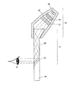
図2及び図3は、ディスプレイ部3の構成を示したものである。図2で、ディスプレイ部3は、通常の眼鏡と同様に、鼻当て6及びテンプル7が備えられるフレーム8と眼鏡レンズ14を有する。このフレーム8及び眼鏡レンズの上端部には、映像表示装置9が備えられる。映像表示装置9は、更に、映像投射装置10と接眼光学系11とからなり、接眼光学系11の一方端部が映像投射装置と接合され両者が一体となっている。眼鏡レンズ14は、垂直方向に接眼光学系11と略同一形状の凹部が形成され、この凹部に眼鏡レンズ14と接眼光学系11との面方向が段差無く一致するように嵌合されている。また、映像表示装置9のブリッジ12側の側面には、CCDカメラ13が備えられ、ケーブル15を介してコントロール部4に映像信号を出力する。なお、第1の実施形態は、撮像手段として小型CCDカメラを適用するが、光学像をデジタイズして出力できるものであればこれに限定するものではなく、CMOSセンサー、人口網膜LSIを用いた撮像機器も適用することが可能である。
2 and 3 show the configuration of the
図3は、映像投射装置10及び接眼光学系11の左側面からの断面を示した側断面図である。映像投射装置10は、ケーブル15を介して、コントロール部4から送信される電子信号を映像光束に変換して映像を接眼光学系11に照射するものである。映像投射装置10の本体となる筐体16の内部には、コントロール部4から送信される映像信号から映像を生成する透過型の液晶表示器17、光源であるLED(Light Emitting Diode)18及びLED18からの照射光を液晶表示器17の全面に導くための照明光学系19を備える。
FIG. 3 is a side sectional view showing a section from the left side of the
接眼光学系11は、更に、プリズム20とホログラム素子21とからなる。プリズム20の上端部は正面方向に厚く形成され、液晶表示器17からの照射される映像光を採光しやすいように上端部が広く形成された楔の形状を有した採光部を備える。LED18及び液晶表示器17から照射される映像は、この採光部から採光され、プリズム20の内部に反射されながら導光が行われるものである。ホログラム素子21は、プリズム20の下端部と眼鏡レンズ14の凹部との間に狭持されるホログラムフィルムである。プリズム20の内部を導光された映像光が照射されることで光の干渉により眼Eに虚像を結ばせるようになっている。本実施形態におけるHMD2は、映像投射装置10及び接眼光学系11等の作用により、観者の視界上に、ホログラム映像を重畳的に表示する外界光透過型のHMDを適用するものである。
The eyepiece
なお、本実施形態では、映像表示装置9を眼鏡レンズ14の一方にのみ備える構成となっているが、図4に示すように、両方の眼鏡レンズに備えて両眼観察を可能とする構成としてもよく、更に左右の映像表示装置で表示される映像を異ならせる構成としてもよい。
In the present embodiment, the
次にコントロール部4について説明する。図5はコントロール部4の構成を示したブロック図である。コントロール部4は、表示駆動装置26、A/D変換器27、外部出力端子28、外部入力端子29、演算処理部C30及び電源ユニット31を備える。
Next, the
表示駆動装置26は、演算処理部C30から出力される映像信号をディスプレイ部3の映像表示装置9に出力するものである。演算処理部C30から出力されるピクセルごとの映像データと、後述するメモリ38に予め記憶された映像表示装置9の表示状態データであるオフセット値とを演算処理し、表示特性を反映させた映像データを生成して映像表示装置9に出力を行うものである。
なおここで、表示状態データとは、映像データと演算が行われる付加データであり、コントラストデータ、輝度データ(輝度の上限や下限等の輝度範囲のデータ等を含む)、映像表示装置9に表示される映像のズーム比(拡大及び縮小等の表示画角データ)及びRGB信号の各チャンネルデータ等をいうものである。即ち、演算処理部C30から出力される映像データと、これらコントラストデータ、輝度データ及びRGB信号の各チャンネルデータ等のオフセット値とを演算することで生成される映像データを映像表示装置9に出力することにより、映像のコントラスト、明るさ、色合い及び階調反転等を可能にする。
The
Here, the display state data is additional data to be calculated with the video data, and is displayed on the
より具体的には、RGBの各チャンネルにおけるピクセルごとのデータが0〜255段階の階調を有するものとする。例えば、映像データの特定のピクセルにおけるRGBの各階調データがそれぞれ100、100、100である場合に、Rチャンネルのオフセット値を+50とし、G及びBのオフセット値をそれぞれ0とすると、表示駆動装置26により映像データの各RGBの階調値が150、100、100となる映像データが生成され、より赤が強くなる映像が表示されることとなる。
More specifically, it is assumed that the data for each pixel in each RGB channel has a gradation of 0 to 255 levels. For example, when the RGB gradation data in a specific pixel of video data is 100, 100, and 100, respectively, if the offset value of the R channel is +50 and the offset values of G and B are 0, display drive The
電源ユニット31は、ディスプレイ部3及びコントロール部4に電力の供給を行う電池である。
なお、本実施の形態では、ディスプレイ部3とコントロール部4とをそれぞれ独立させた構成を採用しているが、両者を一体として構成してもよく又電源ユニット31だけを独立に構成してもよい。
The
In the present embodiment, the configuration in which the
A/D(Analog/Digital)変換器27は、CCDカメラ13から出力されるアナログの映像信号に標本化及び量子化を行い演算処理部C30で処理可能な信号形式であるデジタル信号に変換するものである。外部出力端子28は、演算処理部C30で映像処理等が行われた映像データや各種の制御信号等を映像調節装置5に出力するI/F(Interface)であり、USBやIEEE1394等のケーブルを接続可能とするものである。また、外部入力端子29は、映像調節装置5から出力される各種の指示データや映像データ等が入力されるI/Fである。入力された信号は演算処理部C30に出力されるようになっている。
The A / D (Analog / Digital)
演算処理部C30は、CPU35、ROM36、RAM37、メモリ38、DSP39及びグラフィックメモリ40からなる(図5参照)。CPU35は、演算処理部C30を始め、ヘッドマウントディスプレイ全体の制御を行うものである。ROM36は、不揮発性のヘッドマウントディスプレイ及び映像調節装置5を用いた映像調節に関する各種のプログラムが記憶されたものである。DSP39は、ROM36に記憶されたプログラム及びこれに従って出力されるCPU35の制御信号等に基づいてCCDカメラ13で取得された映像データに映像処理を行うものである。また、グラフィックメモリ40は、DSP39の映像処理により生成された映像データを一時的に保存するとともに、プログラムを展開して映像処理等のワークエリアとして機能するものである。
RAM37は、演算処理部C30で行われる全体処理に関する各種の処理データ等を一時的に記憶するものであり、揮発性の半導体メモリである。また、各種プログラムを展開してワークエリアとして機能するものである。
The arithmetic processing unit C30 includes a
The
メモリ38は、演算処理部C30の演算処理等に使用する各種のデータが記録されるものである。EEPROM(Electrically Erasable Programmable Read Only Memory)、フラッシュメモリ及びハードディスク等を適用することが可能である。本実施の形態では、HMDの携行性に鑑み、小型、軽量且つ衝撃に強く、データの書換え回数に優れるフラッシュメモリを適用している。
The
また、上記メモリ38には、映像表示装置9に表示する映像の表示特性を調節するための表示特性データ(オフセット値)が記憶されている。上記表示駆動装置26は、CPU35から出力される制御信号に従って、メモリ38にアクセスし、記憶されている表示特性データと映像データの演算を行い映像表示装置9に出力するようになっている。なお、表示特性データは、メモリ38のみならずROM36に記憶させることも当然に可能である。後述する映像調節装置5から出力される表示特性データ変更の指示信号に基づいて、変更後の表示特性データへの書換えを行うため、既存の不要なデータの消去及び書込みに優れるフラッシュメモリが好ましい。
The
次に、映像調節装置5について説明する。図6は、映像調節装置5の構成を示したブロック図である。映像調節装置5は、外部入力端子45、外部出力端子46、入力装置54、調節装置用モニタ51及び演算処理部T50を備える。
外部入力端子45及び外部出力端子46は、それぞれHMD2のコントロール部4の外部出力端子28及び外部入力端子29と対応するI/Fであり、各種の指示信号や映像データ等の入出力を行うものである。
Next, the
The
調節装置用モニタ51は、後述する演算処理部T50の制御信号に基づいて、各種の映像を分割表示するものである。図7は、調節装置用モニタ51の画面を示したものである。コントラスト、輝度及びRGBの各チャンネル等各種の表示特性を示す表示特性パラメータW1、観者(顧客)のID番号、HMDのシリアル番号、使用累計時間及び修理履歴等の各種の観者個人に関するデータW2、ディスプレイ部3のCCDカメラ13で取得するカメラ映像W3及び映像表示装置9に表示させる各種の案内指示映像W4を表示する。
表示特性パラメータW1は、表示特性データの各要素毎にレベル値が区分され、HMDの工場出荷時等のデフォルト値を「0」、レベルの上下を各4段階で示されている。また、各要素に表示される○印は、現在の設定を示すものである。
The adjusting device monitor 51 divides and displays various images based on a control signal from the arithmetic processing unit T50 described later. FIG. 7 shows a screen of the adjustment device monitor 51. Data W2 relating to individual viewers such as display characteristic parameters W1 indicating various display characteristics such as contrast, luminance, and RGB channels, viewer (customer) ID number, HMD serial number, accumulated usage time, and repair history. The camera image W3 acquired by the
In the display characteristic parameter W1, the level value is divided for each element of the display characteristic data, the default value at the time of factory shipment of the HMD is “0”, and the upper and lower levels are shown in four stages. In addition, the ◯ mark displayed on each element indicates the current setting.
入力装置54は、映像調節装置5の操作者の操作により演算処理部T50に入力信号を出力するものである。表示特性データの各要素値を変更する信号やその変更後の設定を決定する信号等をCPU55に送信するものである。
なお、調節装置用モニタ51と入力装置54を一体としてタッチパネル形式にすることも当然に可能である。
The
Of course, the adjusting
演算処理部T50は、CPU55、ROM56、RAM57、メモリ58、DSP59及びグラフィックメモリ60からなる。CPU55は、プログラムに従って、映像表示装置9の全体制御を行うものである。ROM56は、CPU55のオペレーションプログラムや表示特性データの変更信号を送信するアプリケーションプログラム等が予め記憶されている不揮発性の半導体メモリである。
なお、後述するが、CPU55は、予め定められた所定の条件に基づいて表示特性データの限界調整値を判断する判断手段として機能するものである。
The arithmetic processing unit T50 includes a
As will be described later, the
RAM57は、CPU55等により実行される全体制御に関わる演算処理の結果が一時的に記憶される不揮発性の半導体メモリである。また、プログラムを展開しワークエリアとして機能するものである。
The
メモリ58は、演算処理部T50での演算に使用するデータが記憶するものである。観者に関する個人データ(観者ID、HMDのシリアル番号、購入日、修理履歴、視力、眼病等の症状及びHMDの表示特性データ等)が予め記憶されたデータベースとして機能する。また、表示特性データの変更がなされた場合に、変更後の表示特性データを記憶するものである。なお、メモリ58としては、EEPROM、フラッシュメモリ又はハードディスク等が適用可能であるが、本実施の形態では、映像調節装置5の汎用性、個人情報等のデータベースとしての機能を鑑み、記憶容量に優れるハードディスクを適用している。
The
DSP59は、外部入力端子45から入力された映像や調節装置用モニタ51に表示させる案内指示映像等に各種の映像処理を行い調節装置用モニタ51に出力するものである。また、グラフィックメモリ60は、DSP59での映像処理の結果を一時的に記憶するとともに、映像処理のプログラムを展開させてワークエリアとして機能するものである。
The
また、電源ユニット52は、映像調節装置5に電力を供給するものであるが、図1に示すように、電力供給の切り替えスイッチとして鍵型スイッチ61を備え、鍵62を挿入して左右に回転することにより電力のオン/オフを制御するようになっている。また、鍵型スイッチ62を、個人情報保護の制御手段又は電力切り替えの制御と個人情報保護の制御との両方の機能を有する構成としてもよい。即ち、調節装置用モニタ51には、観者の個人情報を表示する構成としているが、この表示をするに際して、鍵型スイッチ62をプライベート(PRIVATE)の位置まで更に回転させることで個人情報が表示される構成としてもよい。
なお、HMD2との接続にUSBケーブル等の電力供給型の通信ケーブルを使用する際には、HMD2にも電力を供給する構成とすることも当然に可能である。
In addition, the
It should be noted that when a power supply type communication cable such as a USB cable is used for connection with the
以上のような構成を有するHMD2の映像調整システムの動作について、図8に示すフロー図を用いて説明する。
The operation of the video adjustment system of the
ヘッドマウントディスプレイの映像調節に際しては、図9に示すように、観者M1はディスプレイ部3を装着している状態にあり、観者M1と対面するように映像調節装置5及び調節者M2が位置している。
When adjusting the image of the head mounted display, as shown in FIG. 9, the viewer M1 is wearing the
ヘッドマウントディスプレイ及び映像調節装置5の起動中にヘッドマウントディスプレイの外部入力端子29と外部出力端子46とを接続すると、CPU55より映像調節プログラムの起動コマンドがCPU35に送信される。CPU35は、ROM36アクセスし、映像調節プログラムを読み込み、映像調節プログラムを起動する(ステップS1)。
When the
CPU35は、映像調節プログラムの起動と同時に、外部出力端子28及び外部出力端子46を介して、映像調節プログラムの起動確認コマンド、HMDのシリアル番号データ及びCCDカメラ13で取得した映像データをCPU55に送信する(ステップS2)。
Simultaneously with the start of the video adjustment program, the
CPU55が軌道確認コマンド、個人情報データ及び映像データを受信すると、メモリ58にアクセスし、シリアル番号データに対応する個人情報データ(観者ID、HMDの購入日、修理履歴、観者視力、観者眼病等の種類や症状及びHMDの表示特性データ)を読み込み、調節装置用モニタ51に、観者個人に関するデータW2として表示させる(ステップS3)。また、CCDカメラ13から取得した映像データをDSP59に出力し、調節装置用モニタ51にカメラ映像W3として表示させる(ステップS4)。更に、ROM56にアクセスし、表示特性パラメータの表示に関するデータを読み込むとともに、受信した表示特性データの各値を反映させる演算を行い、現在のHMDの表示特性を示す表示特性パラメータW1を調節装置用モニタ51に表示させる(ステップS5)。
なお、上記個人情報データは、これらは特定の個人情報であることから、表示に際しては観者が固有するパスワードを観者自身によって入力してから調節装置用モニタ51に上記個人情報を表示する構成としてもよい。あるいは、上述のように鍵型スイッチ61を採用する構成とし(図1参照)、PRAIVATE(プライベート)の位置(図1参照)まで操作することで、W2に個人情報を表示させるように制限してもよい。
これにより、映像調節装置5の盗難や人情報の開示を所望しない場合等に、観者のプライバシーを保護することができる。
When the
Since the personal information data is specific personal information, the personal information is displayed on the
Thus, the privacy of the viewer can be protected when the
調節者M2は、問診等により得た観者M1(図9参照)の現状での映像の見え具合及び表示特性の希望等と調節装置用モニタ51に表示される各種の情報とを考慮し、入力装置54を介して、表示特性データの変更指示データをCPU55に送信する。
The adjuster M2 considers the visual appearance and display characteristics of the viewer M1 (refer to FIG. 9) obtained by the inquiry and the like, and various information displayed on the
入力装置54から表示特性データの変更指示データを受信したCPU55は、変更指示データが各パラメータの値の大きさを判別する(ステップS6)。ここで、変更指示データが各パラメータの最大値又は最小値でない場合(又は、予め定められた所定のデータ値を超えない場合)は(ステップS6:NO)、CPU55は、変更指示データをCPU35に送信する(ステップS7)。
The
変更指示データを受信したCPU35は、メモリ38にアクセスし、それまで設定されていた表示特性データ(オフセット値)の書換えを行う(ステップS8)。
The
表示駆動装置26は、CPU35からの制御信号に基づいて、DSP39から出力される映像データと書き換えられたオフセット値とを演算し、表示特性が変更された映像データを映像表示装置9に出力する。映像表示装置9は、表示特性が変更された映像を表示する(ステップS9)。
The
また、上記ステップS6で、変更指示データが各パラメータの最大値又は最小値である場合(又は、予め定められた所定のデータ値を超える場合)は(ステップS6:YES)、CPU55は、DSP59に案内指示映像の表示指示コマンドを送信する(ステップS10)。
DSP59は、ROM56にアクセスし、予め記憶された案内指示データを読み込みCPU55に出力する。CPU55は、調節装置用モニタ51に案内指示データを送信して「これ以上の調節はできません。」という旨の案内指示映像(スーパーインポーズ)W4を表示させる(ステップS11)。又同時に案内指示データと変更指示データとをCPU35に送信する(ステップS12)。
If the change instruction data is the maximum value or the minimum value of each parameter (or exceeds a predetermined data value determined in advance) in step S6 (step S6: YES), the
The
案内指示データ及び変更指示データを受信したCPU35は(ステップS13)、メモリ38にアクセスし、それまで設定されていた表示特性データ(オフセット値)の書換えを行う(ステップS14)。
The
表示駆動装置26は、CPU35からの制御信号に基づいて、DSP39から出力される映像データと書き換えられたオフセット値とを演算し、表示特性の変化した映像データを映像表示装置9に出力する。映像表示装置9は、表示特性が変更された映像を表示する(ステップS9)。
The
また、CPU55は、入力装置54を介して終了コマンドを受信すると、変更指示データをメモリ58に送信し表示特性データを書き換えるとともに、修理履歴データ等を書き換える(ステップS15)。
In addition, when receiving the end command via the
その後、CPU55はCPU35に映像調節プログラムの終了コマンドを送信し、このコマンドを受信したCPU35は映像調節プログラムを終了させ、映像表示装置9に通常の表示を行わせる(ステップS16)。
Thereafter, the
以上のように、本実施の形態におけるHMDの映像調節システムによれば、観者M1が実際に表示特性の変化した映像を確認することができるため、より実用的な映像調節を行うことができる。 As described above, according to the HMD video adjustment system according to the present embodiment, the viewer M1 can check the video whose display characteristics have actually changed, so that more practical video adjustment can be performed. .
また、観者M1と直接対話しながら瞬時且つより詳細な映像調節を行うことができる。このため、特に、視覚障害を有する者のように、比較的極端な表示特性を必要とする場合であっても、調節者M2に専門知識が要求されることなく簡便に表示特性の調節を行うことが可能となる。 In addition, instantaneous and more detailed video adjustment can be performed while directly interacting with the viewer M1. For this reason, even in the case where a relatively extreme display characteristic is required, such as a person with visual impairment, the display characteristic is easily adjusted without requiring expert knowledge of the adjuster M2. It becomes possible.
また、特に、本実施形態におけるHMDのように、ディスプレイ部3として外界光に映像を重畳させる外界光透過型の構成を採用すると、観者M1が一人で映像調節を行うこともできる。また、表示特性データの変更の程度が一定以上になると、調節限界を自動的に判断して案内指示映像が表示されることから、弱視等が原因で、調節装置用モニタ51の表示が確認しづらくても、手の触覚だけで入力装置54を操作することも可能である。また、このような案内指示映像が、映像調節装置5の調節装置用モニタ51にも表示されるため、調節者M2が機械操作に弱い場合でも、簡単に映像の調節を行うことが可能である。
In particular, when an external light transmissive configuration in which an image is superimposed on external light is used as the
更に、変更指示データの内容、即ち、新たに設定しなおしたコントラストデータやRGBの各チャンネルデータ等のオフセット値を映像調節装置5のメモリ58に記憶することから、観者ごとのデータベースを作成することが可能となる。このデータベースの内容を分析することで、観者の視力低下や眼病等の進行具合やHMD2の経年変化や故障による劣化等を判断又は推測が可能となる。更には、このようにして作成されたデータベースから眼病の進行等に関する一定の規定値(例えば、平均的な進行状況等)を予測することも可能となり、この予測データを予めメモリ58等に記憶させ、観者の眼病の進行がこの規定値以上の場合は、その旨の警告(図10参照)を調節装置用モニタ51や映像表示装置9に表示することで医師の診察を促すこともできる。
Further, the contents of the change instruction data, that is, offset values such as newly set contrast data and RGB channel data are stored in the
なお、本実施の形態では、HMDと映像調節装置5を、観者M1と調節者M2とが対面する形式で映像調節システムを使用する構成としたが、外部出力端子28、46及び外部入力端子29、45に代えて又は加えてI/FをNIC(Network Interface Card)等の外部ネットワーク接続機器等を用いてLAN(Local Area Network)、WAN(Wide Area Network)又はインターネット等を介して、遠隔から映像調節を可能とする構成としてもよい。これにより、観者は自宅等に居ながらにして映像調節を行うことが可能となる。
In the present embodiment, the HMD and the
以上、本発明を適用したHMDの映像調節システムについて説明したが、本発明はこれら種々の例に限定されるものではない。 The HMD video adjustment system to which the present invention is applied has been described above, but the present invention is not limited to these various examples.
1 映像調節システム
2 HMD
3 ディスプレイ部
4 コントロール部
5 映像調節装置
6 鼻当て
7 テンプル
8 フレーム
9 映像表示装置
10 映像投射装置
11 接眼光学系
12 ブリッジ
13 CCDカメラ
14 眼鏡レンズ
15 ケーブル
16 筐体
17 液晶表示器
18 LED
19 照明光学系
20 プリズム
21 ホログラム素子
26 表示駆動装置
27 A/D変換器
28 外部出力端子
29 外部入力端子
C30 演算処理部
35 CPU
36 ROM
37 RAM
38 メモリ
39 DSP
40 グラフィックメモリ
45 外部入力端子
46 外部出力端子
T50 演算処理部
51 調節装置用モニタ
52 電源ユニット
54 入力装置
55 CPU
56 ROM
57 RAM
58 メモリ
59 DSP
60 グラフィックメモリ
61 鍵型スイッチ
62 鍵
W1 表示特性パラメータの分割映像
W2 観者個人に関する情報の分割映像
W3 カメラ映像の分割映像
W4 案内指示映像の分割映像
M1 観者
M2 調節者
眼E
1
DESCRIPTION OF
19
36 ROM
37 RAM
38
40
56 ROM
57 RAM
58
60
Claims (6)
前記ヘッドマウントディスプレイは、
映像表示特性データの記憶及び書換えを可能とする記憶手段と、
前記記憶手段に記憶された映像表示特性データに基づいて映像信号の変換を指示する変換指示信号を出力する制御手段と、
前記制御手段から出力される指示信号に基づいて前記映像信号を変換し前記映像表示装置に出力する表示駆動手段とを備え、
前記映像調節装置は、
新たな表示特性データの値を入力する表示特性データ入力手段と、
前記制御手段に、前記表示特性データ入力手段により入力された新たな表示特性データの値及び該新たな表示特性データへの書換えを指示する書換え指示信号を出力する表示特性変更手段を備えることを特徴とするヘッドマウントディスプレイの映像調節システム。 An image adjustment system for a head mounted display comprising a head mounted display including an image display device that displays an image in front of the eyes and an image adjustment device that adjusts an image display characteristic of the head mounted display, wired or wirelessly connected. ,
The head mounted display is
Storage means for enabling storage and rewriting of video display characteristic data;
Control means for outputting a conversion instruction signal for instructing conversion of a video signal based on the video display characteristic data stored in the storage means;
Display driving means for converting the video signal based on an instruction signal output from the control means and outputting the converted video signal to the video display device;
The image adjusting device includes:
Display characteristic data input means for inputting values of new display characteristic data;
The control means includes display characteristic changing means for outputting a new display characteristic data value input by the display characteristic data input means and a rewrite instruction signal for instructing rewriting to the new display characteristic data. Head mounted display image adjustment system.
前記映像調節装置は、前記新たな表示特性データの値を記憶する個別情報記憶手段を更に備え、
前記表示特性変更手段は、前記個別情報記憶手段に、前記新たな表示特性データの値を記憶させることを特徴とするヘッドマウントディスプレイの映像調節システム。 The image adjustment system for a head mounted display according to claim 1,
The video adjusting device further includes individual information storage means for storing the value of the new display characteristic data,
The image adjustment system for a head mounted display, wherein the display characteristic changing unit stores the value of the new display characteristic data in the individual information storage unit.
前記ヘッドマウントディスプレイは、該ヘッドマウントディスプレイに関する識別情報を出力する識別情報出力手段を備え、前記個別情報記憶手段は、前記新たな表示特性データの値と前記識別情報とを対応付けて記憶することを特徴とするヘッドマウントディスプレイの映像調節システム。 The image adjustment system for a head mounted display according to claim 2,
The head mounted display includes identification information output means for outputting identification information relating to the head mounted display, and the individual information storage means stores the value of the new display characteristic data and the identification information in association with each other. An image adjustment system for head mounted displays.
前記映像調節装置は、前記表示特性データのパラメータを表示する調節装置用モニタを更に備えることを特徴とするヘッドマウントディスプレイの映像調節システム。 In the image adjustment system of the head mounted display according to any one of claims 1 to 3,
The image adjustment system according to claim 1, further comprising an adjustment device monitor for displaying a parameter of the display characteristic data.
前記ヘッドマウントディスプレイは、視線方向の映像を捕らえる撮像手段を更に備え、
前記撮像手段で撮影した映像を前記調節装置用モニタに出力することを特徴とするヘッドマウントディスプレイの映像調節システム。 In the image adjustment system of the head mounted display according to any one of claims 1 to 4,
The head mounted display further includes an imaging unit that captures an image in a line-of-sight direction,
An image adjustment system for a head-mounted display, wherein the image taken by the imaging means is output to the adjustment device monitor.
前記映像表示装置は、光学的手段により眼前に光学像を導く映像表示手段と、該映像表示手段に映像を投射する映像投射手段からなり、前記映像表示手段は、外界光を透過可能な支持基盤上に備えられることを特徴とするヘッドマウントディスプレイの映像調節システム。 In the image adjustment system of the head mounted display according to claim 1,
The video display device comprises video display means for guiding an optical image in front of the eyes by optical means, and video projection means for projecting an image on the video display means. The video display means is a support base capable of transmitting external light. An image adjustment system for a head-mounted display, which is provided on the top.
Priority Applications (1)
| Application Number | Priority Date | Filing Date | Title |
|---|---|---|---|
| JP2005019955A JP2006208687A (en) | 2005-01-27 | 2005-01-27 | Video control system for head-mounted display |
Applications Claiming Priority (1)
| Application Number | Priority Date | Filing Date | Title |
|---|---|---|---|
| JP2005019955A JP2006208687A (en) | 2005-01-27 | 2005-01-27 | Video control system for head-mounted display |
Publications (1)
| Publication Number | Publication Date |
|---|---|
| JP2006208687A true JP2006208687A (en) | 2006-08-10 |
Family
ID=36965630
Family Applications (1)
| Application Number | Title | Priority Date | Filing Date |
|---|---|---|---|
| JP2005019955A Pending JP2006208687A (en) | 2005-01-27 | 2005-01-27 | Video control system for head-mounted display |
Country Status (1)
| Country | Link |
|---|---|
| JP (1) | JP2006208687A (en) |
Cited By (7)
| Publication number | Priority date | Publication date | Assignee | Title |
|---|---|---|---|---|
| JP2013210643A (en) * | 2013-04-26 | 2013-10-10 | Sony Corp | Display device and display method |
| JP2014016627A (en) * | 2013-08-29 | 2014-01-30 | Sony Corp | Optical position adjustment method in head-mounted type display |
| US8681256B2 (en) | 2006-10-16 | 2014-03-25 | Sony Corporation | Display method and display apparatus in which a part of a screen area is in a through-state |
| KR20160048800A (en) * | 2013-09-04 | 2016-05-04 | 에씰로아 인터내셔날(콩파니에 제네랄 도프티크) | Methods and systems for augmented reality |
| JP2016526197A (en) * | 2013-04-25 | 2016-09-01 | エシロル アンテルナショナル(コンパーニュ ジェネラル ドプテーク) | How to customize an electronic image display device |
| WO2019098265A1 (en) * | 2017-11-17 | 2019-05-23 | 株式会社テレパシージャパン | Color vision support device |
| US11063822B2 (en) | 2018-08-27 | 2021-07-13 | Toshiba Client Solutions CO., LTD. | Electronic apparatus and control method |
Citations (9)
| Publication number | Priority date | Publication date | Assignee | Title |
|---|---|---|---|---|
| JPH0635659A (en) * | 1992-07-13 | 1994-02-10 | Toshiba Corp | Information processing system |
| JPH0840395A (en) * | 1994-08-02 | 1996-02-13 | Matsushita Electric Ind Co Ltd | Head wearing type image display unit |
| JPH0968672A (en) * | 1995-08-31 | 1997-03-11 | Seiko Epson Corp | Head-mounted type display device and driving method thereof |
| JPH09211376A (en) * | 1996-01-31 | 1997-08-15 | Nissan Motor Co Ltd | Head mounted display device |
| JPH11196352A (en) * | 1997-12-29 | 1999-07-21 | Canon Inc | Head mounted video display device |
| JP2000298246A (en) * | 1999-02-12 | 2000-10-24 | Canon Inc | Device and method for display, and storage medium |
| JP2000347642A (en) * | 1999-06-07 | 2000-12-15 | Seiko Epson Corp | Device and method for image display, and device and method for image processing |
| JP2002268623A (en) * | 2001-03-07 | 2002-09-20 | Fujitsu Ltd | Display system, display device, and computer |
| JP2004260672A (en) * | 2003-02-27 | 2004-09-16 | Minolta Co Ltd | Image display device |
-
2005
- 2005-01-27 JP JP2005019955A patent/JP2006208687A/en active Pending
Patent Citations (9)
| Publication number | Priority date | Publication date | Assignee | Title |
|---|---|---|---|---|
| JPH0635659A (en) * | 1992-07-13 | 1994-02-10 | Toshiba Corp | Information processing system |
| JPH0840395A (en) * | 1994-08-02 | 1996-02-13 | Matsushita Electric Ind Co Ltd | Head wearing type image display unit |
| JPH0968672A (en) * | 1995-08-31 | 1997-03-11 | Seiko Epson Corp | Head-mounted type display device and driving method thereof |
| JPH09211376A (en) * | 1996-01-31 | 1997-08-15 | Nissan Motor Co Ltd | Head mounted display device |
| JPH11196352A (en) * | 1997-12-29 | 1999-07-21 | Canon Inc | Head mounted video display device |
| JP2000298246A (en) * | 1999-02-12 | 2000-10-24 | Canon Inc | Device and method for display, and storage medium |
| JP2000347642A (en) * | 1999-06-07 | 2000-12-15 | Seiko Epson Corp | Device and method for image display, and device and method for image processing |
| JP2002268623A (en) * | 2001-03-07 | 2002-09-20 | Fujitsu Ltd | Display system, display device, and computer |
| JP2004260672A (en) * | 2003-02-27 | 2004-09-16 | Minolta Co Ltd | Image display device |
Cited By (13)
| Publication number | Priority date | Publication date | Assignee | Title |
|---|---|---|---|---|
| US9846304B2 (en) | 2006-10-16 | 2017-12-19 | Sony Corporation | Display method and display apparatus in which a part of a screen area is in a through-state |
| US8681256B2 (en) | 2006-10-16 | 2014-03-25 | Sony Corporation | Display method and display apparatus in which a part of a screen area is in a through-state |
| JP2016526197A (en) * | 2013-04-25 | 2016-09-01 | エシロル アンテルナショナル(コンパーニュ ジェネラル ドプテーク) | How to customize an electronic image display device |
| JP2013210643A (en) * | 2013-04-26 | 2013-10-10 | Sony Corp | Display device and display method |
| JP2014016627A (en) * | 2013-08-29 | 2014-01-30 | Sony Corp | Optical position adjustment method in head-mounted type display |
| KR20160048800A (en) * | 2013-09-04 | 2016-05-04 | 에씰로아 인터내셔날(콩파니에 제네랄 도프티크) | Methods and systems for augmented reality |
| JP2016535872A (en) * | 2013-09-04 | 2016-11-17 | エシロール アンテルナシオナル (コンパニー ジェネラル ドプティック) | Methods and systems for augmented reality |
| US10520730B2 (en) | 2013-09-04 | 2019-12-31 | Essilor International | Methods and systems for augmented reality |
| KR102309257B1 (en) * | 2013-09-04 | 2021-10-06 | 에씰로 앙터나시오날 | Methods and systems for augmented reality |
| WO2019098265A1 (en) * | 2017-11-17 | 2019-05-23 | 株式会社テレパシージャパン | Color vision support device |
| JP2019096939A (en) * | 2017-11-17 | 2019-06-20 | 株式会社テレパシージャパン | Color perception support device |
| JP7011295B2 (en) | 2017-11-17 | 2022-01-26 | Fairy Devices株式会社 | Color vision support device |
| US11063822B2 (en) | 2018-08-27 | 2021-07-13 | Toshiba Client Solutions CO., LTD. | Electronic apparatus and control method |
Similar Documents
| Publication | Publication Date | Title |
|---|---|---|
| JP2006208687A (en) | Video control system for head-mounted display | |
| JP5250834B2 (en) | Head-mounted image display device | |
| CN108535868B (en) | Head-mounted display device and control method thereof | |
| JP2007101618A (en) | Display device | |
| US9921645B2 (en) | Retinal projection device and method for activating a display of a retinal projection device | |
| CN109960481B (en) | Display system and control method thereof | |
| JP6819031B2 (en) | Head-mounted display device, display method | |
| JP2012160898A (en) | Image processing apparatus | |
| US10121409B2 (en) | Display device, method of controlling display device, and program | |
| JP2011209805A (en) | Video display device | |
| CN111988519B (en) | Welding guidance system for providing high-quality images | |
| JP6464729B2 (en) | Display device and control method of display device | |
| JP4604747B2 (en) | Video display device and glasses-type video display device | |
| KR102304916B1 (en) | Welding information providing apparatus | |
| JP4900277B2 (en) | Head-mounted image display device | |
| JP2009075610A (en) | See-through type display device with hazard prevention function and hazard prevention method when see-through type display device is used | |
| US20240061273A1 (en) | Electronic loupe | |
| JP2009192583A (en) | Head-mounted type video display device | |
| JP2017146726A (en) | Movement support device and movement support method | |
| JP2006203440A (en) | External field light transmission type head mount display | |
| JP2007104036A (en) | Display device | |
| JP2008113317A (en) | Remote operation support system | |
| JP2017161759A (en) | Retina projection type display device, image display method and program | |
| CN107896322A (en) | The control method and storage medium of projection arrangement, projection arrangement | |
| JP6609920B2 (en) | Display device and control method of display device |
Legal Events
| Date | Code | Title | Description |
|---|---|---|---|
| A625 | Written request for application examination (by other person) |
Free format text: JAPANESE INTERMEDIATE CODE: A625 Effective date: 20071024 |
|
| A711 | Notification of change in applicant |
Free format text: JAPANESE INTERMEDIATE CODE: A711 Effective date: 20110202 |
|
| A521 | Written amendment |
Free format text: JAPANESE INTERMEDIATE CODE: A821 Effective date: 20110203 |
|
| A977 | Report on retrieval |
Free format text: JAPANESE INTERMEDIATE CODE: A971007 Effective date: 20110322 |
|
| A131 | Notification of reasons for refusal |
Free format text: JAPANESE INTERMEDIATE CODE: A131 Effective date: 20110405 |
|
| A02 | Decision of refusal |
Free format text: JAPANESE INTERMEDIATE CODE: A02 Effective date: 20110809 |