EP3018916A1 - Techniques for generating audio signals - Google Patents
Techniques for generating audio signals Download PDFInfo
- Publication number
- EP3018916A1 EP3018916A1 EP15200544.3A EP15200544A EP3018916A1 EP 3018916 A1 EP3018916 A1 EP 3018916A1 EP 15200544 A EP15200544 A EP 15200544A EP 3018916 A1 EP3018916 A1 EP 3018916A1
- Authority
- EP
- European Patent Office
- Prior art keywords
- frequency
- speaker
- wave
- shutter
- frequencies
- Prior art date
- Legal status (The legal status is an assumption and is not a legal conclusion. Google has not performed a legal analysis and makes no representation as to the accuracy of the status listed.)
- Granted
Links
- 230000005236 sound signal Effects 0.000 title claims abstract description 52
- 238000000034 method Methods 0.000 title claims abstract description 37
- 239000012528 membrane Substances 0.000 claims abstract description 70
- 230000033001 locomotion Effects 0.000 claims description 16
- 230000010355 oscillation Effects 0.000 claims description 9
- 230000004044 response Effects 0.000 claims description 4
- 230000000694 effects Effects 0.000 claims description 3
- 238000004519 manufacturing process Methods 0.000 claims 1
- 230000000644 propagated effect Effects 0.000 claims 1
- 238000004891 communication Methods 0.000 description 22
- 238000006073 displacement reaction Methods 0.000 description 8
- 238000010586 diagram Methods 0.000 description 7
- 238000004590 computer program Methods 0.000 description 6
- 230000006870 function Effects 0.000 description 6
- 230000008569 process Effects 0.000 description 6
- 238000005516 engineering process Methods 0.000 description 4
- 239000000758 substrate Substances 0.000 description 4
- 230000002093 peripheral effect Effects 0.000 description 3
- 238000010276 construction Methods 0.000 description 2
- 238000013500 data storage Methods 0.000 description 2
- 239000000835 fiber Substances 0.000 description 2
- 230000003287 optical effect Effects 0.000 description 2
- 125000006850 spacer group Chemical group 0.000 description 2
- XUIMIQQOPSSXEZ-UHFFFAOYSA-N Silicon Chemical compound [Si] XUIMIQQOPSSXEZ-UHFFFAOYSA-N 0.000 description 1
- 230000001133 acceleration Effects 0.000 description 1
- 238000003491 array Methods 0.000 description 1
- 230000005540 biological transmission Effects 0.000 description 1
- 238000007667 floating Methods 0.000 description 1
- 230000003993 interaction Effects 0.000 description 1
- 230000007246 mechanism Effects 0.000 description 1
- 239000003607 modifier Substances 0.000 description 1
- 229910052710 silicon Inorganic materials 0.000 description 1
- 239000010703 silicon Substances 0.000 description 1
- 239000007787 solid Substances 0.000 description 1
- 238000001228 spectrum Methods 0.000 description 1
- 230000003068 static effect Effects 0.000 description 1
- 230000002123 temporal effect Effects 0.000 description 1
- 230000007723 transport mechanism Effects 0.000 description 1
Images


Classifications
-
- H—ELECTRICITY
- H04—ELECTRIC COMMUNICATION TECHNIQUE
- H04R—LOUDSPEAKERS, MICROPHONES, GRAMOPHONE PICK-UPS OR LIKE ACOUSTIC ELECTROMECHANICAL TRANSDUCERS; DEAF-AID SETS; PUBLIC ADDRESS SYSTEMS
- H04R1/00—Details of transducers, loudspeakers or microphones
- H04R1/20—Arrangements for obtaining desired frequency or directional characteristics
- H04R1/22—Arrangements for obtaining desired frequency or directional characteristics for obtaining desired frequency characteristic only
-
- G—PHYSICS
- G10—MUSICAL INSTRUMENTS; ACOUSTICS
- G10K—SOUND-PRODUCING DEVICES; METHODS OR DEVICES FOR PROTECTING AGAINST, OR FOR DAMPING, NOISE OR OTHER ACOUSTIC WAVES IN GENERAL; ACOUSTICS NOT OTHERWISE PROVIDED FOR
- G10K15/00—Acoustics not otherwise provided for
- G10K15/04—Sound-producing devices
-
- H—ELECTRICITY
- H04—ELECTRIC COMMUNICATION TECHNIQUE
- H04R—LOUDSPEAKERS, MICROPHONES, GRAMOPHONE PICK-UPS OR LIKE ACOUSTIC ELECTROMECHANICAL TRANSDUCERS; DEAF-AID SETS; PUBLIC ADDRESS SYSTEMS
- H04R1/00—Details of transducers, loudspeakers or microphones
-
- H—ELECTRICITY
- H04—ELECTRIC COMMUNICATION TECHNIQUE
- H04R—LOUDSPEAKERS, MICROPHONES, GRAMOPHONE PICK-UPS OR LIKE ACOUSTIC ELECTROMECHANICAL TRANSDUCERS; DEAF-AID SETS; PUBLIC ADDRESS SYSTEMS
- H04R1/00—Details of transducers, loudspeakers or microphones
- H04R1/20—Arrangements for obtaining desired frequency or directional characteristics
- H04R1/22—Arrangements for obtaining desired frequency or directional characteristics for obtaining desired frequency characteristic only
- H04R1/28—Transducer mountings or enclosures modified by provision of mechanical or acoustic impedances, e.g. resonator, damping means
-
- H—ELECTRICITY
- H04—ELECTRIC COMMUNICATION TECHNIQUE
- H04R—LOUDSPEAKERS, MICROPHONES, GRAMOPHONE PICK-UPS OR LIKE ACOUSTIC ELECTROMECHANICAL TRANSDUCERS; DEAF-AID SETS; PUBLIC ADDRESS SYSTEMS
- H04R17/00—Piezoelectric transducers; Electrostrictive transducers
-
- H—ELECTRICITY
- H04—ELECTRIC COMMUNICATION TECHNIQUE
- H04R—LOUDSPEAKERS, MICROPHONES, GRAMOPHONE PICK-UPS OR LIKE ACOUSTIC ELECTROMECHANICAL TRANSDUCERS; DEAF-AID SETS; PUBLIC ADDRESS SYSTEMS
- H04R19/00—Electrostatic transducers
- H04R19/02—Loudspeakers
-
- H—ELECTRICITY
- H04—ELECTRIC COMMUNICATION TECHNIQUE
- H04R—LOUDSPEAKERS, MICROPHONES, GRAMOPHONE PICK-UPS OR LIKE ACOUSTIC ELECTROMECHANICAL TRANSDUCERS; DEAF-AID SETS; PUBLIC ADDRESS SYSTEMS
- H04R31/00—Apparatus or processes specially adapted for the manufacture of transducers or diaphragms therefor
-
- H—ELECTRICITY
- H04—ELECTRIC COMMUNICATION TECHNIQUE
- H04R—LOUDSPEAKERS, MICROPHONES, GRAMOPHONE PICK-UPS OR LIKE ACOUSTIC ELECTROMECHANICAL TRANSDUCERS; DEAF-AID SETS; PUBLIC ADDRESS SYSTEMS
- H04R9/00—Transducers of moving-coil, moving-strip, or moving-wire type
-
- H—ELECTRICITY
- H04—ELECTRIC COMMUNICATION TECHNIQUE
- H04R—LOUDSPEAKERS, MICROPHONES, GRAMOPHONE PICK-UPS OR LIKE ACOUSTIC ELECTROMECHANICAL TRANSDUCERS; DEAF-AID SETS; PUBLIC ADDRESS SYSTEMS
- H04R1/00—Details of transducers, loudspeakers or microphones
- H04R1/02—Casings; Cabinets ; Supports therefor; Mountings therein
- H04R1/023—Screens for loudspeakers
-
- H—ELECTRICITY
- H04—ELECTRIC COMMUNICATION TECHNIQUE
- H04R—LOUDSPEAKERS, MICROPHONES, GRAMOPHONE PICK-UPS OR LIKE ACOUSTIC ELECTROMECHANICAL TRANSDUCERS; DEAF-AID SETS; PUBLIC ADDRESS SYSTEMS
- H04R19/00—Electrostatic transducers
- H04R19/005—Electrostatic transducers using semiconductor materials
-
- H—ELECTRICITY
- H04—ELECTRIC COMMUNICATION TECHNIQUE
- H04R—LOUDSPEAKERS, MICROPHONES, GRAMOPHONE PICK-UPS OR LIKE ACOUSTIC ELECTROMECHANICAL TRANSDUCERS; DEAF-AID SETS; PUBLIC ADDRESS SYSTEMS
- H04R2201/00—Details of transducers, loudspeakers or microphones covered by H04R1/00 but not provided for in any of its subgroups
- H04R2201/003—Mems transducers or their use
-
- H—ELECTRICITY
- H04—ELECTRIC COMMUNICATION TECHNIQUE
- H04R—LOUDSPEAKERS, MICROPHONES, GRAMOPHONE PICK-UPS OR LIKE ACOUSTIC ELECTROMECHANICAL TRANSDUCERS; DEAF-AID SETS; PUBLIC ADDRESS SYSTEMS
- H04R2217/00—Details of magnetostrictive, piezoelectric, or electrostrictive transducers covered by H04R15/00 or H04R17/00 but not provided for in any of their subgroups
- H04R2217/03—Parametric transducers where sound is generated or captured by the acoustic demodulation of amplitude modulated ultrasonic waves
-
- H—ELECTRICITY
- H04—ELECTRIC COMMUNICATION TECHNIQUE
- H04R—LOUDSPEAKERS, MICROPHONES, GRAMOPHONE PICK-UPS OR LIKE ACOUSTIC ELECTROMECHANICAL TRANSDUCERS; DEAF-AID SETS; PUBLIC ADDRESS SYSTEMS
- H04R2499/00—Aspects covered by H04R or H04S not otherwise provided for in their subgroups
- H04R2499/10—General applications
- H04R2499/11—Transducers incorporated or for use in hand-held devices, e.g. mobile phones, PDA's, camera's
-
- Y—GENERAL TAGGING OF NEW TECHNOLOGICAL DEVELOPMENTS; GENERAL TAGGING OF CROSS-SECTIONAL TECHNOLOGIES SPANNING OVER SEVERAL SECTIONS OF THE IPC; TECHNICAL SUBJECTS COVERED BY FORMER USPC CROSS-REFERENCE ART COLLECTIONS [XRACs] AND DIGESTS
- Y10—TECHNICAL SUBJECTS COVERED BY FORMER USPC
- Y10T—TECHNICAL SUBJECTS COVERED BY FORMER US CLASSIFICATION
- Y10T29/00—Metal working
- Y10T29/49—Method of mechanical manufacture
- Y10T29/49002—Electrical device making
- Y10T29/49005—Acoustic transducer
Definitions
- the present disclosure generally relates to techniques for generating an audio signal and in some examples to methods and apparatuses for generating an audio signal on mobile devices.
- a speaker is a device that generates acoustic signals.
- a speaker usually includes an electromagnetically actuated piston which creates a local pressure in the air. The pressure transverses the medium as an acoustic signal and is interpreted by an ear to register as sound.
- Some embodiments of the present disclosure may generally relate to a speaker device that includes a membrane and a shutter.
- the membrane is positioned in a first plane and configured to oscillate along a first directional path and at a first frequency effective to generate an ultrasonic acoustic signal.
- the shutter is positioned in a second plane that is substantially separated from the first plane. The shutter is configured to modulate the ultrasonic acoustic signal such that an audio signal is generated.
- the speaker array may include a first speaker and a second speaker.
- the first speaker includes a first membrane and a first shutter.
- the second speaker includes a second membrane and a second shutter.
- the first membrane may be configured to oscillate in a first directional path and at a first frequency effective to generate a first ultrasonic acoustic signal.
- the first shutter may be positioned above the first membrane and configured to modulate the first ultrasonic acoustic signal such that a first audio signal is generated.
- the second membrane may be configured to oscillate in the first directional path and at a second frequency effective to generate a second ultrasonic acoustic signal.
- the second shutter may be positioned above the second membrane and configured to modulate the second ultrasonic acoustic signal such that a second audio signal is generated.
- Additional embodiments of the present disclosure may generally relate to methods for generating an audio signal.
- One example method may include selectively oscillating a membrane located in a first plane along a first directional path and at a first frequency effective to generate an ultrasonic acoustic signal and selectively moving a shutter positioned in a second plane that is separated from the first plane effective to modulate the ultrasonic acoustic signal and generate an audio signal.
- This disclosure is drawn, inter alia, to methods, apparatus, computer programs, and systems of generating an audio signal.
- a speaker device in some embodiments, includes a membrane and a shutter.
- the membrane can be configured to oscillate along a first directional path and at a first frequency effective to generate an ultrasonic acoustic signal.
- the shutter is positioned proximate to the membrane.
- the speaker may further include a blind.
- the blind may be positioned between the membrane and the shutter, or alternatively positioned above the membrane and the shutter.
- the membrane, the blind, and the shutter may be positioned in a substantially parallel orientation with respect to each other.
- the shutter can be configured to move along a second directional path that is substantially perpendicular (orthogonal) to the first directional path. By the movement of the shutter, the shutter can be configured to modulate the ultrasonic acoustic signal such that an audio signal can be generated.
- the shutter can be adapted to move at a second frequency along the second directional path.
- the generated audio signal from the shutter has a frequency which is substantially equal to the difference between the first frequency and the second frequency.
- the shutter may be implemented as a comb drive actuator.
- the comb drive actuator may include a moving comb and a static comb.
- a first signal may be applied to the shutter by a controller to initiate the movement of the comb drive actuator.
- the shutter may further include a spring configured to push the moving comb back to its original position. The application of the first signal and the force of the spring can thus be adapted to control movement of the shutter in a backwards and forwards motion along the second directional path.
- the membrane may be implemented as a capacitive micromachined ultrasonic transducer.
- a second signal may be applied to the membrane by the controller.
- the membrane can be oscillated along the first directional path in response to the application of the second signal through the electrostatic effect.
- the shutter may move along the second directional path between a first position and a second position.
- the distance between the first position and the second position can be substantially equal to a distance between two adjacent openings of the first set of openings on the blind.
- the shutter may also include a second set of openings.
- the first set of openings can be aligned with the second set of openings.
- the first set of openings are no longer aligned with the second set of openings. The relationship and orientation of the first set of openings relative to the second set of openings will be further described below.
- the membrane is driven by an electric signal that oscillates at a frequency ⁇ and hence moves at Cos(2pi* ⁇ t).
- this electric signal has a portion that is derived from an audio signal A(t).
- B(f) is the spectrum of the audio signal
- delta(f) is the Dirac delta function
- a speaker array may include at least two speaker devices set forth above.
- the speaker array may include a first speaker device and a second speaker device.
- the first speaker device can include a first membrane and a first shutter.
- the second speaker device can include a second membrane and a second shutter.
- the first membrane can be configured to oscillate along a first directional path and at a first frequency effective to generate a first ultrasonic acoustic signal.
- the first shutter can be positioned above the first membrane and configured to modulate the frequency of the first ultrasonic acoustic signal effective to generate a first audio signal.
- the second membrane can be configured to oscillate along the first directional path and at a second frequency effective to generate a second ultrasonic acoustic signal.
- the second shutter can be positioned above the second membrane and configured to modulate the frequency of the second ultrasonic acoustic signal effective to generate a second audio signal.
- the first frequency and the second frequency may be substantially the same.
- the first shutter may be configured to move at a third frequency along a second directional path which is substantially perpendicular (e.g., orthogonal) to the first directional path.
- the second shutter may be configured to move at a fourth frequency along the second directional path.
- the third frequency and the fourth frequency may be substantially the same or different from one another. While the first shutter can be adapted to cover the top of the first speaker device, the second shutter may be simultaneously adapted to cover the top of the second speaker device. In some examples, while the first shutter can be adapted to cover the top of the first speaker device, the second shutter may be simultaneously adapted to reveal an opening at the top of the second speaker device.
- a method for generating an audio signal includes selectively oscillating a membrane along a first directional path and at a first frequency effective to generate an ultrasonic acoustic signal and selectively moving a shutter positioned above the membrane to modulate the ultrasonic acoustic signal effective and generate the audio signal.
- the shutter may be moved along a second directional path that is substantially perpendicular (e.g., normal or orthogonal) to the first directional path at a second frequency between a first position and a second position.
- the difference between the first frequency and the second frequency may be substantially equal to the frequency of the audio signal.
- FIG. 1A is a cross sectional view of an illustrative embodiment of speaker device 100 arranged in accordance with at least some embodiments of the present disclosure.
- Speaker device 100 includes shutter 101, blind 103, membrane 105, substrate 107, controller 109, and spacers 111.
- Speaker device 100 may be a micro electro mechanical system (MEMS) and pico-sized. Therefore, speaker device 100 may be suitable for mobile devices because of its compact size.
- Substrate 107 can be a silicon substrate of a micro electro mechanical system.
- Spacers 111 can be configured to separate shutter 101, blind 103, membrane 105, and substrate 107.
- Membrane 105 can be electrically coupled to controller 109. Controller 109 can be configured to apply a first signal 115 to membrane 105. In response to first signal 115, membrane 105 can oscillate along a directional path 190 effective to generate ultrasonic acoustic wave 117. Ultrasonic acoustic wave 117 may propagate along the directional path 190 from membrane 105 towards blind 103 and shutter 101.
- first alternating signal 115 may be a voltage or a current that alternates according to a first frequency.
- first alternating signal 115 may be some other variety of periodically changing signal such as a current or voltage that may be sinusoidal, pulsed, ramped, triangular, linearly changing, non-linearly changing, or some combination thereof.
- the oscillation frequency of membrane 105 can be substantially proportional to the frequency of first alternating signal 115. Therefore, by applying different alternating signals 115, controller 109 can control the oscillation frequency of membrane 105.
- Blind 103 can be positioned above membrane 105 and below shutter 101.
- Blind 103 can include a first set of rectangular openings (not shown).
- Ultrasonic acoustic wave 117 passes through the openings of blind 103 through to shutter 101.
- Shutter 101 is electrically coupled to controller 109. Controller 109 can be configured to apply a second signal 113 to shutter 101. In response to second signal 113, shutter 101 can moves along a directional path 192 between a first position and a second position. Shutter 101 includes a second set of openings (not shown). The relationship and orientation of the first set of openings relative to the second set of openings will be further described below.
- FIG. 1B is a perspective view of an illustrative embodiment of speaker device 100 set forth above and arranged in accordance with at least some embodiments of the present disclosure.
- Shutter 101 includes a second set of openings 121.
- the second set of openings 121 is in alignment (shown with dotted lines) with the first set of openings 123 of blind 103.
- Ultrasonic acoustic signal 117 could as a result directly pass through blind 103 and shutter 101 through the first set of openings 123 and the second set of openings 121, respectively.
- FIG. 1C is another perspective view of an illustrative embodiment of speaker device 100 set forth above and in accordance with at least some embodiments of the present disclosure.
- the displacement between the first position and the second position is given as displacement d 1 .
- the displacement d 1 may be equal to the distance d 2 between two adjacent openings of the first set of openings 123.
- FIG. 2 is a top view of an illustrative embodiment of speaker array 200, arranged in accordance with at least some embodiments of the present disclosure.
- Speaker array 200 can include a first speaker device 210 and a second speaker device 220.
- First speaker device 210 can include a first shutter 211 and a first membrane 213.
- First shutter 211 and first membrane 213 are both electrically coupled to controller 230.
- Controller 230 can be configured to apply a first signal to first shutter 211 and a second signal to first membrane 213.
- the moving frequency of first shutter 211 and the oscillation frequency of first membrane 213 can be associated with the first signal and the second signal, respectively.
- a first audio signal can be generated based on the movement of the first shutter 211 and the oscillating membrane 213.
- Second speaker device 220 can include a second shutter 221 and a second membrane 223. Second shutter 221 and second membrane 223 are both electrically coupled to controller 230. Controller 230 can be configured to apply a third signal to second shutter 221 and a fourth signal to second membrane 223. As set forth above, the moving frequency of second shutter 221 and the oscillation frequency of second membrane 223 are associated with the third signal and the fourth signal, respectively. A second audio signal can be generated based on the movement of the second shutter 221 and the oscillating membrane 223.
- the first audio signal can be generated by first speaker device 210 and the second audio signal can be generated by second speaker device 220 have substantially the same frequency.
- the moving frequencies of first shutter 211 and second shutter 221 are different, or the oscillation frequencies of first membrane 213 and second membrane 223 are different, the first audio signal generated by first speaker 210 and the second audio signal generated by second speaker 220 have substantially different frequencies.
- Generating different audio signals from various elements in the speaker array can be used for generating psychoacoustic effects creating the illusion of novel sound location or unique temporal effects in the acoustic signal.
- FIG. 3 is a flow chart of an illustrative embodiment of method 300 for generating an audio signal in accordance with at least some embodiments of the present disclosure.
- Method 300 may begin at block 301.
- example method 300 includes oscillating a membrane located in a first plane along a first directional path and at a first frequency effective to generate an ultrasonic acoustic signal. Method 300 may further include applying a first signal to the membrane to initiate the oscillation. The method may continue at block 303.
- the example method 300 includes moving a shutter positioned in a second plane that is separated from the first plane effective to modulate the ultrasonic acoustic signal and generate the audio signal.
- the shutter may move along a second directional path substantially perpendicular to the first directional path and at a second frequency.
- the shutter may have a displacement along the second directional path. The displacement will typically not be greater than a distance between two adjacent openings on the blind.
- the frequency of the generated audio signal may be substantially equal to the difference between the first frequency and the second frequency.
- FIG. 4 shows a block diagram illustrating a computer program product 400 that is arranged for generating an audio signal in accordance with at least some embodiments of the present disclosure.
- Computer program product 400 may include signal bearing medium 404, which may include one or more sets of executable instructions 402 that, when executed by, for example, a processor of a computing device, may provide at least the functionality described above and illustrated in FIG. 3 .
- signal bearing medium 404 may encompass non-transitory computer readable medium 408, such as, but not limited to, a hard disk drive, a Compact Disc (CD), a Digital Versatile Disk (DVD), a digital tape, memory, etc.
- signal bearing medium 404 may encompass recordable medium 410, such as, but not limited to, memory, read/write (R/W) CDs, R/W DVDs, etc.
- signal bearing medium 404 may encompass communications medium 406, such as, but not limited to, a digital and/or an analog communication medium (e.g., a fiber optic cable, a waveguide, a wired communications link, a wireless communication link, etc.)
- Computer program product 400 may also be recorded in non-transitory computer readable medium 408 or another similar recordable medium 410.
- FIG. 5 shows a block diagram of an illustrative embodiment of a computing device that is arranged for generating an audio signal in accordance with at least some embodiments of the present disclosure.
- computing device 500 typically includes one or more processors 510 and a system memory 520.
- a memory bus 530 may be used for communicating between processor 510 and system memory 520.
- processor 510 may be of any type including but not limited to a microprocessor ( ⁇ P), a microcontroller ( ⁇ C), a digital signal processor (DSP), or any combination thereof.
- Processor 510 may include one more levels of caching, such as a level one cache 511 and a level two cache 512, a processor core 513, and registers 514.
- An example processor core 513 may include an arithmetic logic unit (ALU), a floating point unit (FPU), a digital signal processing core (DSP Core), or any combination thereof.
- An example memory controller 515 may also be used with processor 510, or in some implementations memory controller 515 may be an internal part of processor 510.
- system memory 520 may be of any type including but not limited to volatile memory (such as RAM), non-volatile memory (such as ROM, flash memory, etc.) or any combination thereof.
- System memory 520 may include an operating system 521, one or more applications 522, and program data 524.
- application 522 may include an audio signal generation algorithm 523 that is arranged to perform the functions as described herein including those described with respect to the steps 301 and 303 of the method 300 of FIG. 3 .
- Program data 524 may include audio signal generation data sets 525 that may be useful for the operation of audio signal generation algorithm 523 as will be further described below.
- the audio signal generation data sets 525 may include, without limitation, a first signal level and a second signal level which oscillates the membrane and moves the shutter, respectively.
- application 522 may be arranged to operate with program data 524 on operating system 521 such that implementations of selecting preferred data set may be provided as described herein. This described basic configuration 501 is illustrated in FIG. 5 by those components within the inner dashed line.
- application 522 may include audio signal generation algorithm 523 that is arranged to perform the functions as described herein including those described with respect to the steps 301 and 303 of the method 300 of FIG. 3 .
- Computing device 500 may have additional features or functionality, and additional interfaces to facilitate communications between basic configuration 501 and any required devices and interfaces.
- a bus/interface controller 540 may be used to facilitate communications between basic configuration 501 and one or more data storage devices 550 via a storage interface bus 541.
- Data storage devices 550 may be removable storage devices 551, non-removable storage devices 552, or a combination thereof.
- Examples of removable storage and non-removable storage devices include magnetic disk devices such as flexible disk drives and hard-disk drives (HDD), optical disk drives such as compact disk (CD) drives or digital versatile disk (DVD) drives, solid state drives (SSD), and tape drives to name a few.
- Example computer storage media may include volatile and nonvolatile, removable and non-removable media implemented in any method or technology for storage of information, such as computer readable instructions, data structures, program modules, or other data.
- Computer storage media includes, but is not limited to, RAM, ROM, EEPROM, flash memory or other memory technology, CD-ROM, digital versatile disks (DVD) or other optical storage, magnetic cassettes, magnetic tape, magnetic disk storage or other magnetic storage devices, or any other medium which may be used to store the desired information and which may be accessed by computing device 500. Any such computer storage media may be part of computing device 500.
- Computing device 500 may also include an interface bus 542 for facilitating communication from various interface devices (e.g., output devices 560, peripheral interfaces 570, and communication devices 580) to basic configuration 501 via bus/interface controller 540.
- Example output devices 560 include a graphics processing unit 561 and an audio processing unit 562, which may be configured to communicate to various external devices such as a display or speakers via one or more A/V ports 563.
- Example peripheral interfaces 570 include a serial interface controller 571 or a parallel interface controller 572, which may be configured to communicate with external devices such as input devices (e.g., keyboard, mouse, pen, voice input device, touch input device, etc.) or other peripheral devices (e.g., printer, scanner, etc.) via one or more I/O ports 573.
- An example communication device 580 includes a network controller 581, which may be arranged to facilitate communications with one or more other computing devices 590 over a network communication link via one or more communication ports 582.
- the other computing devices 590 may include other applications, which may be operated based on the results of the application 522.
- the network communication link may be one example of a communication media.
- Communication media may typically be embodied by computer readable instructions, data structures, program modules, or other data in a modulated data signal, such as a carrier wave or other transport mechanism, and may include any information delivery media.
- a "modulated data signal" may be a signal that has one or more of its characteristics set or changed in such a manner as to encode information in the signal.
- communication media may include wired media such as a wired network or direct-wired connection, and wireless media such as acoustic, radio frequency (RF), microwave, infrared (IR) and other wireless media.
- RF radio frequency
- IR infrared
- the term computer readable media as used herein may include both storage media and communication media.
- Computing device 500 may be implemented as a portion of a small-form factor portable (or mobile) electronic device such as a cell phone, a personal data assistant (PDA), a personal media player device, a wireless web-watch device, a personal headset device, an application specific device, or a hybrid device that include any of the above functions.
- a small-form factor portable (or mobile) electronic device such as a cell phone, a personal data assistant (PDA), a personal media player device, a wireless web-watch device, a personal headset device, an application specific device, or a hybrid device that include any of the above functions.
- PDA personal data assistant
- Computing device 500 may also be implemented as a personal computer including both laptop computer and non-laptop computer configurations.
- the implementer may opt for a mainly hardware and/or firmware vehicle; if flexibility is paramount, the implementer may opt for a mainly software implementation; or, yet again alternatively, the implementer may opt for some combination of hardware, software, and/or firmware.
- Examples of a signal bearing medium include, but are not limited to, the following: a recordable type medium such as a floppy disk, a hard disk drive, a Compact Disc (CD), a Digital Versatile Disk (DVD), a digital tape, a computer memory, etc.; and a transmission type medium such as a digital and/or an analog communication medium (e.g., a fiber optic cable, a waveguide, a wired communications link, a wireless communication link, etc.).
- a typical data processing system generally includes one or more of a system unit housing, a video display device, a memory such as volatile and non-volatile memory, processors such as microprocessors and digital signal processors, computational entities such as operating systems, drivers, graphical user interfaces, and applications programs, one or more interaction devices, such as a touch pad or screen, and/or control systems including feedback loops and control motors (e.g., feedback for sensing position and/or velocity; control motors for moving and/or adjusting components and/or quantities).
- a typical data processing system may be implemented utilizing any suitable commercially available components, such as those typically found in data computing/communication and/or network computing/communication systems.
- any two components so associated can also be viewed as being “operably connected”, or “operably coupled”, to each other to achieve the desired functionality, and any two components capable of being so associated can also be viewed as being “operably couplable”, to each other to achieve the desired functionality.
- operably couplable include but are not limited to physically mateable and/or physically interacting components and/or wirelessly interactable and/or wirelessly interacting components and/or logically interacting and/or logically interactable components.
Landscapes
- Engineering & Computer Science (AREA)
- Physics & Mathematics (AREA)
- Acoustics & Sound (AREA)
- Signal Processing (AREA)
- Health & Medical Sciences (AREA)
- Otolaryngology (AREA)
- Manufacturing & Machinery (AREA)
- Multimedia (AREA)
- Transducers For Ultrasonic Waves (AREA)
- Obtaining Desirable Characteristics In Audible-Bandwidth Transducers (AREA)
- Circuit For Audible Band Transducer (AREA)
- Diaphragms For Electromechanical Transducers (AREA)
- Soundproofing, Sound Blocking, And Sound Damping (AREA)
Abstract
Description
- The present disclosure generally relates to techniques for generating an audio signal and in some examples to methods and apparatuses for generating an audio signal on mobile devices.
- A speaker is a device that generates acoustic signals. A speaker usually includes an electromagnetically actuated piston which creates a local pressure in the air. The pressure transverses the medium as an acoustic signal and is interpreted by an ear to register as sound.
- Some embodiments of the present disclosure may generally relate to a speaker device that includes a membrane and a shutter. The membrane is positioned in a first plane and configured to oscillate along a first directional path and at a first frequency effective to generate an ultrasonic acoustic signal. The shutter is positioned in a second plane that is substantially separated from the first plane. The shutter is configured to modulate the ultrasonic acoustic signal such that an audio signal is generated.
- Other embodiments of the present disclosure may generally relate to a speaker array. The speaker array may include a first speaker and a second speaker. The first speaker includes a first membrane and a first shutter. The second speaker includes a second membrane and a second shutter. The first membrane may be configured to oscillate in a first directional path and at a first frequency effective to generate a first ultrasonic acoustic signal. The first shutter may be positioned above the first membrane and configured to modulate the first ultrasonic acoustic signal such that a first audio signal is generated. The second membrane may be configured to oscillate in the first directional path and at a second frequency effective to generate a second ultrasonic acoustic signal. The second shutter may be positioned above the second membrane and configured to modulate the second ultrasonic acoustic signal such that a second audio signal is generated.
- Additional embodiments of the present disclosure may generally relate to methods for generating an audio signal. One example method may include selectively oscillating a membrane located in a first plane along a first directional path and at a first frequency effective to generate an ultrasonic acoustic signal and selectively moving a shutter positioned in a second plane that is separated from the first plane effective to modulate the ultrasonic acoustic signal and generate an audio signal.
- The foregoing summary is illustrative only and is not intended to be in any way limiting. In addition to the illustrative aspects, embodiments, and features described above, further aspects, embodiments, and features will become apparent by reference to the drawings and the following detailed description.
- The foregoing and other features of the present disclosure will become more fully apparent from the following description and appended claims, taken in conjunction with the accompanying drawings. Understanding that these drawings depict only several embodiments in accordance with the disclosure and are therefore not to be considered limiting of its scope, the disclosure will be described with additional specificity and detail through use of the accompanying drawings.
-
FIG. 1A is a cross sectional view of an illustrative embodiment of a speaker; -
FIG. 1B is a perspective view of an illustrative embodiment of a speaker; -
FIG. 1C is another perspective view of an illustrative embodiment of a speaker; -
FIG. 2 is a top view of an illustrative embodiment of a speaker array; -
FIG. 3 is a flow chart of an illustrative embodiment of a method for generating an audio signal; -
FIG. 4 shows a block diagram illustrating a computer program product that is arranged for generating an audio signal; and -
FIG. 5 shows a block diagram of an illustrative embodiment of a computing device that is arranged for generating an audio signal, - In the following detailed description, reference is made to the accompanying drawings, which form a part hereof. In the drawings, similar symbols typically identify similar components, unless context dictates otherwise. The illustrative embodiments described in the detailed description, drawings, and claims are not meant to be limiting. Other embodiments may be utilized, and other changes may be made, without departing from the spirit or scope of the subject matter presented here. It will be readily understood that the aspects of the present disclosure, as generally described herein, and illustrated in the figures, can be arranged, substituted, combined, and designed in a wide variety of different configurations, all of which are explicitly contemplated and make part of this disclosure.
- This disclosure is drawn, inter alia, to methods, apparatus, computer programs, and systems of generating an audio signal.
- In some embodiments, a speaker device is described that includes a membrane and a shutter. The membrane can be configured to oscillate along a first directional path and at a first frequency effective to generate an ultrasonic acoustic signal. The shutter is positioned proximate to the membrane. The speaker may further include a blind. The blind may be positioned between the membrane and the shutter, or alternatively positioned above the membrane and the shutter. The membrane, the blind, and the shutter may be positioned in a substantially parallel orientation with respect to each other.
- The shutter can be configured to move along a second directional path that is substantially perpendicular (orthogonal) to the first directional path. By the movement of the shutter, the shutter can be configured to modulate the ultrasonic acoustic signal such that an audio signal can be generated. The shutter can be adapted to move at a second frequency along the second directional path. The generated audio signal from the shutter has a frequency which is substantially equal to the difference between the first frequency and the second frequency.
- In some examples, the shutter may be implemented as a comb drive actuator. The comb drive actuator may include a moving comb and a static comb. A first signal may be applied to the shutter by a controller to initiate the movement of the comb drive actuator. The shutter may further include a spring configured to push the moving comb back to its original position. The application of the first signal and the force of the spring can thus be adapted to control movement of the shutter in a backwards and forwards motion along the second directional path.
- In some examples, the membrane may be implemented as a capacitive micromachined ultrasonic transducer. A second signal may be applied to the membrane by the controller. The membrane can be oscillated along the first directional path in response to the application of the second signal through the electrostatic effect.
- The shutter may move along the second directional path between a first position and a second position. The distance between the first position and the second position can be substantially equal to a distance between two adjacent openings of the first set of openings on the blind.
- The shutter may also include a second set of openings. When the shutter is at the first position, the first set of openings can be aligned with the second set of openings. When the shutter is at the second position, the first set of openings are no longer aligned with the second set of openings. The relationship and orientation of the first set of openings relative to the second set of openings will be further described below.
- In some embodiments, suppose the membrane is driven by an electric signal that oscillates at a frequency Ω and hence moves at Cos(2pi*Ωt). Suppose further that this electric signal has a portion that is derived from an audio signal A(t). The acoustic signal, which corresponds to the acoustic pressure related to the acceleration of the membrane, may be characterized as:


- Suppose we apply to this S(f) a shutter also oscillating at frequency Ω, then in time domain, the mathematical relationship may be characterized as:


- In some other embodiments, a speaker array may include at least two speaker devices set forth above. For example, the speaker array may include a first speaker device and a second speaker device. The first speaker device can include a first membrane and a first shutter. The second speaker device can include a second membrane and a second shutter. The first membrane can be configured to oscillate along a first directional path and at a first frequency effective to generate a first ultrasonic acoustic signal. The first shutter can be positioned above the first membrane and configured to modulate the frequency of the first ultrasonic acoustic signal effective to generate a first audio signal. The second membrane can be configured to oscillate along the first directional path and at a second frequency effective to generate a second ultrasonic acoustic signal. The second shutter can be positioned above the second membrane and configured to modulate the frequency of the second ultrasonic acoustic signal effective to generate a second audio signal. In some examples, the first frequency and the second frequency may be substantially the same.
- The first shutter may be configured to move at a third frequency along a second directional path which is substantially perpendicular (e.g., orthogonal) to the first directional path. The second shutter may be configured to move at a fourth frequency along the second directional path. The third frequency and the fourth frequency may be substantially the same or different from one another. While the first shutter can be adapted to cover the top of the first speaker device, the second shutter may be simultaneously adapted to cover the top of the second speaker device. In some examples, while the first shutter can be adapted to cover the top of the first speaker device, the second shutter may be simultaneously adapted to reveal an opening at the top of the second speaker device.
- In some other embodiments, a method for generating an audio signal includes selectively oscillating a membrane along a first directional path and at a first frequency effective to generate an ultrasonic acoustic signal and selectively moving a shutter positioned above the membrane to modulate the ultrasonic acoustic signal effective and generate the audio signal.
- The shutter may be moved along a second directional path that is substantially perpendicular (e.g., normal or orthogonal) to the first directional path at a second frequency between a first position and a second position. The difference between the first frequency and the second frequency may be substantially equal to the frequency of the audio signal.
-
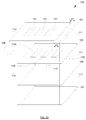
FIG. 1A is a cross sectional view of an illustrative embodiment ofspeaker device 100 arranged in accordance with at least some embodiments of the present disclosure.Speaker device 100 includesshutter 101, blind 103,membrane 105,substrate 107,controller 109, andspacers 111.Speaker device 100 may be a micro electro mechanical system (MEMS) and pico-sized. Therefore,speaker device 100 may be suitable for mobile devices because of its compact size.Substrate 107 can be a silicon substrate of a micro electro mechanical system.Spacers 111 can be configured toseparate shutter 101, blind 103,membrane 105, andsubstrate 107. -
Membrane 105 can be electrically coupled tocontroller 109.Controller 109 can be configured to apply afirst signal 115 tomembrane 105. In response tofirst signal 115,membrane 105 can oscillate along adirectional path 190 effective to generate ultrasonicacoustic wave 117. Ultrasonicacoustic wave 117 may propagate along thedirectional path 190 frommembrane 105 towards blind 103 andshutter 101. - In some examples, first alternating
signal 115 may be a voltage or a current that alternates according to a first frequency. In some other examples, first alternatingsignal 115 may be some other variety of periodically changing signal such as a current or voltage that may be sinusoidal, pulsed, ramped, triangular, linearly changing, non-linearly changing, or some combination thereof. The oscillation frequency ofmembrane 105 can be substantially proportional to the frequency of first alternatingsignal 115. Therefore, by applying different alternatingsignals 115,controller 109 can control the oscillation frequency ofmembrane 105. - Blind 103 can be positioned above
membrane 105 and belowshutter 101. Blind 103 can include a first set of rectangular openings (not shown). Ultrasonicacoustic wave 117 passes through the openings of blind 103 through to shutter 101. -
Shutter 101 is electrically coupled tocontroller 109.Controller 109 can be configured to apply asecond signal 113 to shutter 101. In response tosecond signal 113,shutter 101 can moves along adirectional path 192 between a first position and a second position.Shutter 101 includes a second set of openings (not shown). The relationship and orientation of the first set of openings relative to the second set of openings will be further described below. -
FIG. 1B is a perspective view of an illustrative embodiment ofspeaker device 100 set forth above and arranged in accordance with at least some embodiments of the present disclosure.Shutter 101 includes a second set ofopenings 121. Whenshutter 101 is at a first position, as shown inFIG. 1B , the second set ofopenings 121 is in alignment (shown with dotted lines) with the first set ofopenings 123 of blind 103. Ultrasonicacoustic signal 117 could as a result directly pass through blind 103 and shutter 101 through the first set ofopenings 123 and the second set ofopenings 121, respectively. -
FIG. 1C is another perspective view of an illustrative embodiment ofspeaker device 100 set forth above and in accordance with at least some embodiments of the present disclosure. Whenshutter 101 is at a second position, as shown inFIG. 1C , the displacement between the first position and the second position is given as displacement d1. The displacement d1 may be equal to the distance d2 between two adjacent openings of the first set ofopenings 123. -
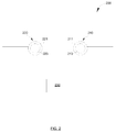
FIG. 2 is a top view of an illustrative embodiment ofspeaker array 200, arranged in accordance with at least some embodiments of the present disclosure.Speaker array 200 can include afirst speaker device 210 and asecond speaker device 220.First speaker device 210 can include afirst shutter 211 and afirst membrane 213.First shutter 211 andfirst membrane 213 are both electrically coupled tocontroller 230.Controller 230 can be configured to apply a first signal tofirst shutter 211 and a second signal tofirst membrane 213. As set forth above, the moving frequency offirst shutter 211 and the oscillation frequency offirst membrane 213 can be associated with the first signal and the second signal, respectively. A first audio signal can be generated based on the movement of thefirst shutter 211 and theoscillating membrane 213. -
Second speaker device 220 can include asecond shutter 221 and asecond membrane 223.Second shutter 221 andsecond membrane 223 are both electrically coupled tocontroller 230.Controller 230 can be configured to apply a third signal tosecond shutter 221 and a fourth signal tosecond membrane 223. As set forth above, the moving frequency ofsecond shutter 221 and the oscillation frequency ofsecond membrane 223 are associated with the third signal and the fourth signal, respectively. A second audio signal can be generated based on the movement of thesecond shutter 221 and theoscillating membrane 223. - When the moving frequencies of
first shutter 211 andsecond shutter 221, and the oscillation frequencies offirst membrane 213 andsecond membrane 223 are substantially the same, the first audio signal can be generated byfirst speaker device 210 and the second audio signal can be generated bysecond speaker device 220 have substantially the same frequency. When the moving frequencies offirst shutter 211 andsecond shutter 221 are different, or the oscillation frequencies offirst membrane 213 andsecond membrane 223 are different, the first audio signal generated byfirst speaker 210 and the second audio signal generated bysecond speaker 220 have substantially different frequencies. Generating different audio signals from various elements in the speaker array can be used for generating psychoacoustic effects creating the illusion of novel sound location or unique temporal effects in the acoustic signal. -
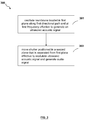
FIG. 3 is a flow chart of an illustrative embodiment ofmethod 300 for generating an audio signal in accordance with at least some embodiments of the present disclosure.Method 300 may begin atblock 301. - At
block 301,example method 300 includes oscillating a membrane located in a first plane along a first directional path and at a first frequency effective to generate an ultrasonic acoustic signal.Method 300 may further include applying a first signal to the membrane to initiate the oscillation. The method may continue atblock 303. - At
block 303, theexample method 300 includes moving a shutter positioned in a second plane that is separated from the first plane effective to modulate the ultrasonic acoustic signal and generate the audio signal. The shutter may move along a second directional path substantially perpendicular to the first directional path and at a second frequency. The shutter may have a displacement along the second directional path. The displacement will typically not be greater than a distance between two adjacent openings on the blind. The frequency of the generated audio signal may be substantially equal to the difference between the first frequency and the second frequency. -
FIG. 4 shows a block diagram illustrating acomputer program product 400 that is arranged for generating an audio signal in accordance with at least some embodiments of the present disclosure.Computer program product 400 may include signal bearing medium 404, which may include one or more sets ofexecutable instructions 402 that, when executed by, for example, a processor of a computing device, may provide at least the functionality described above and illustrated inFIG. 3 . - In some implementations, signal bearing medium 404 may encompass non-transitory computer
readable medium 408, such as, but not limited to, a hard disk drive, a Compact Disc (CD), a Digital Versatile Disk (DVD), a digital tape, memory, etc. In some implementations, signal bearing medium 404 may encompassrecordable medium 410, such as, but not limited to, memory, read/write (R/W) CDs, R/W DVDs, etc. In some implementations, signal bearing medium 404 may encompasscommunications medium 406, such as, but not limited to, a digital and/or an analog communication medium (e.g., a fiber optic cable, a waveguide, a wired communications link, a wireless communication link, etc.)Computer program product 400 may also be recorded in non-transitory computerreadable medium 408 or anothersimilar recordable medium 410. -
FIG. 5 shows a block diagram of an illustrative embodiment of a computing device that is arranged for generating an audio signal in accordance with at least some embodiments of the present disclosure. In a very basic configuration 501,computing device 500 typically includes one ormore processors 510 and asystem memory 520. A memory bus 530 may be used for communicating betweenprocessor 510 andsystem memory 520. - Depending on the desired configuration,
processor 510 may be of any type including but not limited to a microprocessor (µP), a microcontroller (µC), a digital signal processor (DSP), or any combination thereof.Processor 510 may include one more levels of caching, such as a level one cache 511 and a level two cache 512, aprocessor core 513, and registers 514. Anexample processor core 513 may include an arithmetic logic unit (ALU), a floating point unit (FPU), a digital signal processing core (DSP Core), or any combination thereof. Anexample memory controller 515 may also be used withprocessor 510, or in someimplementations memory controller 515 may be an internal part ofprocessor 510. - Depending on the desired configuration,
system memory 520 may be of any type including but not limited to volatile memory (such as RAM), non-volatile memory (such as ROM, flash memory, etc.) or any combination thereof.System memory 520 may include anoperating system 521, one ormore applications 522, andprogram data 524. In some embodiments,application 522 may include an audiosignal generation algorithm 523 that is arranged to perform the functions as described herein including those described with respect to thesteps method 300 ofFIG. 3 .Program data 524 may include audio signal generation data sets 525 that may be useful for the operation of audiosignal generation algorithm 523 as will be further described below. In some embodiments, the audio signal generation data sets 525 may include, without limitation, a first signal level and a second signal level which oscillates the membrane and moves the shutter, respectively. In some embodiments,application 522 may be arranged to operate withprogram data 524 onoperating system 521 such that implementations of selecting preferred data set may be provided as described herein. This described basic configuration 501 is illustrated inFIG. 5 by those components within the inner dashed line. - In some other embodiments,
application 522 may include audiosignal generation algorithm 523 that is arranged to perform the functions as described herein including those described with respect to thesteps method 300 ofFIG. 3 . -
Computing device 500 may have additional features or functionality, and additional interfaces to facilitate communications between basic configuration 501 and any required devices and interfaces. For example, a bus/interface controller 540 may be used to facilitate communications between basic configuration 501 and one or moredata storage devices 550 via a storage interface bus 541.Data storage devices 550 may beremovable storage devices 551,non-removable storage devices 552, or a combination thereof. Examples of removable storage and non-removable storage devices include magnetic disk devices such as flexible disk drives and hard-disk drives (HDD), optical disk drives such as compact disk (CD) drives or digital versatile disk (DVD) drives, solid state drives (SSD), and tape drives to name a few. Example computer storage media may include volatile and nonvolatile, removable and non-removable media implemented in any method or technology for storage of information, such as computer readable instructions, data structures, program modules, or other data. -
System memory 520,removable storage devices 551 andnon-removable storage devices 552 are examples of computer storage media. Computer storage media includes, but is not limited to, RAM, ROM, EEPROM, flash memory or other memory technology, CD-ROM, digital versatile disks (DVD) or other optical storage, magnetic cassettes, magnetic tape, magnetic disk storage or other magnetic storage devices, or any other medium which may be used to store the desired information and which may be accessed by computingdevice 500. Any such computer storage media may be part ofcomputing device 500. -
Computing device 500 may also include an interface bus 542 for facilitating communication from various interface devices (e.g.,output devices 560,peripheral interfaces 570, and communication devices 580) to basic configuration 501 via bus/interface controller 540.Example output devices 560 include agraphics processing unit 561 and an audio processing unit 562, which may be configured to communicate to various external devices such as a display or speakers via one or more A/V ports 563. Exampleperipheral interfaces 570 include aserial interface controller 571 or aparallel interface controller 572, which may be configured to communicate with external devices such as input devices (e.g., keyboard, mouse, pen, voice input device, touch input device, etc.) or other peripheral devices (e.g., printer, scanner, etc.) via one or more I/O ports 573. Anexample communication device 580 includes anetwork controller 581, which may be arranged to facilitate communications with one or moreother computing devices 590 over a network communication link via one ormore communication ports 582. In some embodiments, theother computing devices 590 may include other applications, which may be operated based on the results of theapplication 522. - The network communication link may be one example of a communication media. Communication media may typically be embodied by computer readable instructions, data structures, program modules, or other data in a modulated data signal, such as a carrier wave or other transport mechanism, and may include any information delivery media. A "modulated data signal" may be a signal that has one or more of its characteristics set or changed in such a manner as to encode information in the signal. By way of example, and not limitation, communication media may include wired media such as a wired network or direct-wired connection, and wireless media such as acoustic, radio frequency (RF), microwave, infrared (IR) and other wireless media. The term computer readable media as used herein may include both storage media and communication media.
-
Computing device 500 may be implemented as a portion of a small-form factor portable (or mobile) electronic device such as a cell phone, a personal data assistant (PDA), a personal media player device, a wireless web-watch device, a personal headset device, an application specific device, or a hybrid device that include any of the above functions.Computing device 500 may also be implemented as a personal computer including both laptop computer and non-laptop computer configurations. - There is little distinction left between hardware and software implementations of aspects of systems; the use of hardware or software is generally (but not always, in that in certain contexts the choice between hardware and software can become significant) a design choice representing cost versus efficiency tradeoffs. There are various vehicles by which processes and/or systems and/or other technologies described herein can be effected (e.g., hardware, software, and/or firmware), and that the preferred vehicle will vary with the context in which the processes and/or systems and/or other technologies are deployed. For example, if an implementer determines that speed and accuracy are paramount, the implementer may opt for a mainly hardware and/or firmware vehicle; if flexibility is paramount, the implementer may opt for a mainly software implementation; or, yet again alternatively, the implementer may opt for some combination of hardware, software, and/or firmware.
- The foregoing detailed description has set forth various embodiments of the devices and/or processes via the use of block diagrams, flowcharts, and/or examples. Insofar as such block diagrams, flowcharts, and/or examples contain one or more functions and/or operations, it will be understood by those within the art that each function and/or operation within such block diagrams, flowcharts, or examples can be implemented, individually and/or collectively, by a wide range of hardware, software, firmware, or virtually any combination thereof. In one embodiment, several portions of the subject matter described herein may be implemented via Application Specific Integrated Circuits (ASICs), Field Programmable Gate Arrays (FPGAs), digital signal processors (DSPs), or other integrated formats. However, those skilled in the art will recognize that some aspects of the embodiments disclosed herein, in whole or in part, can be equivalently implemented in integrated circuits, as one or more computer programs running on one or more computers (e.g., as one or more programs running on one or more computer systems), as one or more programs running on one or more processors (e.g., as one or more programs running on one or more microprocessors), as firmware, or as virtually any combination thereof, and that designing the circuitry and/or writing the code for the software and or firmware would be well within the skill of one of skill in the art in light of this disclosure. In addition, those skilled in the art will appreciate that the mechanisms of the subject matter described herein are capable of being distributed as a program product in a variety of forms, and that an illustrative embodiment of the subject matter described herein applies regardless of the particular type of signal bearing medium used to actually carry out the distribution. Examples of a signal bearing medium include, but are not limited to, the following: a recordable type medium such as a floppy disk, a hard disk drive, a Compact Disc (CD), a Digital Versatile Disk (DVD), a digital tape, a computer memory, etc.; and a transmission type medium such as a digital and/or an analog communication medium (e.g., a fiber optic cable, a waveguide, a wired communications link, a wireless communication link, etc.).
- Those skilled in the art will recognize that it is common within the art to describe devices and/or processes in the fashion set forth herein, and thereafter use engineering practices to integrate such described devices and/or processes into data processing systems. That is, at least a portion of the devices and/or processes described herein can be integrated into a data processing system via a reasonable amount of experimentation. Those having skill in the art will recognize that a typical data processing system generally includes one or more of a system unit housing, a video display device, a memory such as volatile and non-volatile memory, processors such as microprocessors and digital signal processors, computational entities such as operating systems, drivers, graphical user interfaces, and applications programs, one or more interaction devices, such as a touch pad or screen, and/or control systems including feedback loops and control motors (e.g., feedback for sensing position and/or velocity; control motors for moving and/or adjusting components and/or quantities). A typical data processing system may be implemented utilizing any suitable commercially available components, such as those typically found in data computing/communication and/or network computing/communication systems.
- The herein described subject matter sometimes illustrates different components contained within, or connected with, different other components. It is to be understood that such depicted architectures are merely exemplary, and that in fact many other architectures can be implemented which achieve the same functionality. In a conceptual sense, any arrangement of components to achieve the same functionality is effectively "associated" such that the desired functionality is achieved. Hence, any two components herein combined to achieve a particular functionality can be seen as "associated with" each other such that the desired functionality is achieved, irrespective of architectures or intermedial components. Likewise, any two components so associated can also be viewed as being "operably connected", or "operably coupled", to each other to achieve the desired functionality, and any two components capable of being so associated can also be viewed as being "operably couplable", to each other to achieve the desired functionality. Specific examples of operably couplable include but are not limited to physically mateable and/or physically interacting components and/or wirelessly interactable and/or wirelessly interacting components and/or logically interacting and/or logically interactable components.
- With respect to the use of substantially any plural and/or singular terms herein, those having skill in the art can translate from the plural to the singular and/or from the singular to the plural as is appropriate to the context and/or application. The various singular/plural permutations may be expressly set forth herein for sake of clarity.
- It will be understood by those within the art that, in general, terms used herein, and especially in the appended claims (e.g., bodies of the appended claims) are generally intended as "open" terms (e.g., the term "including" should be interpreted as "including but not limited to," the term "having" should be interpreted as "having at least," the term "includes" should be interpreted as "includes but is not limited to," etc.). It will be further understood by those within the art that if a specific number of an introduced claim recitation is intended, such an intent will be explicitly recited in the claim, and in the absence of such recitation no such intent is present. For example, as an aid to understanding, the following appended claims may contain usage of the introductory phrases "at least one" and "one or more" to introduce claim recitations. However, the use of such phrases should not be construed to imply that the introduction of a claim recitation by the indefinite articles "a" or "an" limits any particular claim containing such introduced claim recitation to disclosures containing only one such recitation, even when the same claim includes the introductory phrases "one or more" or "at least one" and indefinite articles such as "a" or "an" (e.g., "a" and/or "an" should typically be interpreted to mean "at least one" or "one or more"); the same holds true for the use of definite articles used to introduce claim recitations. In addition, even if a specific number of an introduced claim recitation is explicitly recited, those skilled in the art will recognize that such recitation should typically be interpreted to mean at least the recited number (e.g., the bare recitation of "two recitations," without other modifiers, typically means at least two recitations, or two or more recitations). Furthermore, in those instances where a convention analogous to "at least one of A, B, and C, etc." is used, in general such a construction is intended in the sense one having skill in the art would understand the convention (e.g., "a system having at least one of A, B, and C" would include but not be limited to systems that have A alone, B alone, C alone, A and B together, A and C together, B and C together, and/or A, B, and C together, etc.). In those instances where a convention analogous to "at least one of A, B, or C, etc." is used, in general such a construction is intended in the sense one having skill in the art would understand the convention (e.g., "a system having at least one of A, B, or C" would include but not be limited to systems that have A alone, B alone, C alone, A and B together, A and C together, B and C together, and/or A, B, and C together, etc.). It will be further understood by those within the art that virtually any disjunctive word and/or phrase presenting two or more alternative terms, whether in the description, claims, or drawings, should be understood to contemplate the possibilities of including one of the terms, either of the terms, or both terms. For example, the phrase "A or B" will be understood to include the possibilities of "A" or "B" or "A and B."
- While various aspects and embodiments have been disclosed herein, other aspects and embodiments will be apparent to those skilled in the art. The various aspects and embodiments disclosed herein are for purposes of illustration and are not intended to be limiting, with the true scope and spirit being indicated by the following claims.
- This application further encompasses the following items:
- 1. A speaker device, comprising:
- a membrane positioned in a first plane, wherein the membrane is configured to oscillate along a first directional path and at a first frequency effective to generate an ultrasonic acoustic signal; and
- a shutter positioned in a second plane that is substantially separated from the first plane, wherein the shutter is configured to modulate the ultrasonic acoustic signal such that an audio signal is generated.
- 2. The speaker device of
claim 1, wherein the shutter is configured effective to move along a second directional path substantially perpendicular to the first directional path. - 3. The speaker device of
claim 2, wherein the shutter is configured to move along the second directional path at a second frequency, wherein the frequency of the audio signal is substantially equal to the difference between the first frequency and the second frequency. - 4. The speaker device of
claim 2, further comprising a blind positioned in a third plane located between the membrane in the first plane and the shutter in the second plane. - 5. The speaker device of claim 4, wherein the membrane, the blind, and the shutter are positioned in planes that are substantially parallel to each other.
- 6. The speaker device of claim 4, wherein the shutter is configured to move along the second directional path between a first position and a second position defining a displacement along the second directional path, wherein the displacement is substantially equal to a distance between two adjacent openings of the first set of openings of the blind.
- 7. The speaker device of claim 6, wherein the shutter includes a second set of openings.
- 8. The speaker device of claim 7, wherein when the shutter is at the first position, the first set of openings are substantially aligned with the second set of openings.
- 9. The speaker device of
claim 2, further comprising a blind positioned in a third plane that is substantially separated from the first plane and the second plane. - 10. The speaker device of
claim 1, the membrane and the shutter comprising an individual speaker from an array of speakers in the speaker device. - 11. A method for generating an audio signal, comprising:
- selectively oscillating a membrane located in a first plane along a first directional path and at a first frequency effective to generate an ultrasonic acoustic signal; and
- selectively moving a shutter positioned in a second plane that is separated from the first plane effective to modulate the ultrasonic acoustic signal and generate the audio signal.
- 12. The method of
claim 11, wherein moving the shutter further comprises moving the shutter along a second directional path substantially perpendicular to the first directional path. - 13. The method of claim 12, further comprising moving the shutter along the second directional path at a second frequency, wherein the frequency of the audio signal is substantially equal to the difference between the first frequency and the second frequency.
- 14. The method of claim 12, wherein moving the shutter along the second directional path further comprises moving the shutter between a first position and a second position.
- 15. The method of claim 14, wherein a displacement between the first position and the second position is associated with a distance between two adjacent openings on the blind.
- 16. A speaker array, comprising:
- a first speaker device, comprising
- a first membrane positioned in a first plane, wherein the first membrane is configured to oscillate along a first directional path and at a first frequency effective to generate a first ultrasonic acoustic signal; and
- a first shutter positioned in a second plane that is substantially separated from the first plane, wherein the first shutter is configured to modulate the first ultrasonic acoustic signal such that a first audio signal is generated; and
- a second speaker device, comprising
- a second membrane positioned in the first plane, wherein the second membrane is configured to oscillate along the first directional path and at a second frequency effective to generate a second ultrasonic acoustic signal; and
- a second shutter positioned in the second plane, wherein the second shutter is configured to modulate the second ultrasonic acoustic signal such that a second audio signal is generated.
- a first speaker device, comprising
- 16. The speaker array of claim 15, wherein the first frequency and the second frequency are substantially the same.
- 17. The speaker array of claim 15, wherein the first shutter is configured to move at a third frequency along a second directional path substantially perpendicular to the first directional path, the second shutter is configured to move at a fourth frequency along the second directional path.
- 18. The speaker array of claim 17, wherein the third frequency and the fourth frequency are substantially the same.
- 19. The speaker array of claim 18, wherein the first shutter is simultaneously adapted to cover the top of the first speaker device, while the second shutter is adapted to cover the top of the second speaker device.
- 20. The speaker array of claim 18, wherein the first shutter is simultaneously adapted to cover the top of the first speaker device, while the second shutter is adapted to reveal an opening at the top of the second speaker device.
Claims (23)
- A speaker apparatus, comprising:a first member positioned at a first location and configured to move along a first direction to generate a signal that has a frequency within a first range of frequencies; anda second member positioned at a second location spaced apart from the first location, and configured to move along a second direction, so as to operate on the signal that has the frequency within the first range of frequencies to generate a signal that has a frequency within a second range of frequencies,wherein the second range of frequencies is lower than the first range of frequencies.
- The speaker apparatus of claim 1,
wherein the second frequency range includes an audio frequency range and wherein the first frequency range includes an ultrasonic frequency range, or
wherein the first member is positioned at the first location along a first plane that is generally parallel to a second plane along which the second member is positioned at the second location, or
wherein the first member is configured to orthogonally move along the first direction relative to movement of the second member along the second direction. - The speaker apparatus of claim 1, wherein the first member is configured to move along the first direction by oscillation at a first frequency, and wherein the second member is configured to move along the second direction at a second frequency different from the first frequency.
- The speaker apparatus of claim 3, wherein the signal that has the frequency within the second range of frequencies has a frequency that is substantially equal to a difference between the first and second frequencies.
- The speaker apparatus of claim 1, wherein the second member is configured to move along the second direction between a first position and a second position, the speaker apparatus further comprising a third member spaced from the first and second members, and configured as a blind element with a first set of openings, wherein a distance between the first position and the second position is substantially equal to a distance between two consecutive openings in the first set of openings.
- The speaker apparatus of claim 5, wherein:the second member is configured with a second set of openings;at the first position of the second member, the first set of openings are aligned with the second set of openings; andat the second position of the second member, the first set of openings are misaligned with the second set of openings.
- The speaker apparatus of claim 5, wherein the third element is positioned at a third location that is spaced from and in between the first location where the first member is positioned and the second location where the second member is positioned.
- The speaker apparatus of claim 1, further comprising at least one controller configured to apply a first control signal to the second member to initiate movement of the second member along the second direction, and configured to apply a second control signal to the first member to initiate movement of the first member along the first direction.
- The speaker apparatus of claim 8, wherein the first member is formed as a capacitive micro-machined element that moves in response to electrostatic effect caused by application of the second signal.
- The speaker apparatus of claim 1, wherein the first and second members comprise parts of a first speaker device, and wherein the speaker apparatus further comprises a second speaker device similar to the first speaker device.
- The speaker apparatus of claim 10, wherein the first and second speaker devices have a respective opening at their top that can be covered and revealed during operation, and wherein during operation:the second member is configured during its movement to cover the top of the first speaker device while the top of the second speaker device is covered, and to reveal the top of the first speaker device while the top of the second speaker device is revealed; orthe second member is configured to cover the top of the first speaker device while the top of the second speaker device is revealed, and to reveal the top of the first speaker device while the top of the second speaker device is covered.
- The speaker apparatus of claim 10, wherein the signal generated by the second member that has the frequency within the second range of frequencies includes an audio signal, and wherein the first speaker device and the second speaker device are configured to be respectively operated with
control signals with a same control signal frequency, so as to enable the first and second speaker devices to generate audio signals with a same audio signal frequency within the second range of frequencies, or
control signals having different control signal frequencies, so as to enable the first and second speaker devices to generate audio signals with different audio signal frequencies within the second range of frequencies. - A speaker apparatus, comprising:a microelectromechanical system, MEMS, speaker device that includes:a first element configured to receive electrostatic actuation to oscillate at a first frequency so as to generate a first wave;a second element configured to move at a second frequency different from the first frequency,wherein the first wave generated by the first element is incident on the second element, and wherein movement of the second element enables the second element to operate on the first wave so as to generate a second wave.
- The speaker apparatus of claim 13,
wherein the second wave has a frequency within an audio frequency range, and wherein the first wave has a frequency within an ultrasonic frequency range, or
wherein the second element is spaced apart from the first element, and wherein the first and second elements are arranged in generally parallel respective planes. - The speaker apparatus of claim 13, wherein the second element is configured with at least one opening, and wherein the MEMS speaker device further includes a third element configured to at least partially cover and reveal the at least one opening of the second element as the second element moves.
- The speaker apparatus of claim 15,
wherein the third element is located between the first element and the second element, or
wherein the third element is located above the first element and the second element. - The speaker apparatus of claim 13, further comprising a computing device that includes at least one controller configured to generate at least one control signal to respectively control oscillation of the first element and movement of the second element.
- A method to generate an output wave from a speaker device, the method comprising:actuating a first element to move so as to generate a first wave with a frequency within a first range of frequencies;directing the generated first wave to propagate along a waveguide;receiving, at a second element, the generated first wave that has propagated along the waveguide; andactuating the second element to move so as to operate on the received first wave to generate the output wave, wherein the output wave has a frequency in a second range of frequencies that includes an audio range of frequencies.
- The method of claim 18, wherein actuating the first element to move so as to generate the first wave with the frequency within the first range of frequencies includes:actuating the first element to move so as to provide the first wave with an ultrasonic frequency.
- The method of claim 18, wherein actuating the second element to move includes actuating the second element to move in a direction different from a direction of movement of the first element.
- The method of claim 20, wherein actuating the second element to move in the direction different from the direction of movement of the first element includes:actuating the second element to move in a generally orthogonal direction relative to the direction of movement of the first element.
- The method of claim 18, wherein actuating the second element to move so as to operate on the received first wave includes:moving the second element to a first position to enable at least one opening of the second element to align with at least one opening of a third element, so as to enable the first wave to pass through the aligned at least one openings;moving the second element to a second position to enable at least one opening of the second element to be mis-aligned with at least one opening of a third element; andrepeatedly moving the second element between the first and second positions.
- A method to manufacture a microelectromechanical system ,MEMS, speaker device, the method comprising:forming a membrane element configured to oscillate at a first frequency so as to generate a first wave;forming a shutter element configured to move at a second frequency different from the first frequency; andspacing the shutter element apart from the membrane element to at least partially define a waveguide between the spaced apart first and second elements, so as to enable the generated first wave to propagate within the waveguide from the membrane element to the shutter element,wherein movement of the shutter element enables the shutter element to operate on the first wave so as to generate a second wave.
Priority Applications (1)
| Application Number | Priority Date | Filing Date | Title |
|---|---|---|---|
| EP15200544.3A EP3018916B1 (en) | 2011-08-16 | 2011-08-16 | Techniques for generating audio signals |
Applications Claiming Priority (3)
| Application Number | Priority Date | Filing Date | Title |
|---|---|---|---|
| EP11870957.5A EP2745536B1 (en) | 2011-08-16 | 2011-08-16 | Techniques for generating audio signals |
| PCT/US2011/047833 WO2013025199A1 (en) | 2011-08-16 | 2011-08-16 | Techniques for generating audio signals |
| EP15200544.3A EP3018916B1 (en) | 2011-08-16 | 2011-08-16 | Techniques for generating audio signals |
Related Parent Applications (2)
| Application Number | Title | Priority Date | Filing Date |
|---|---|---|---|
| EP11870957.5A Division-Into EP2745536B1 (en) | 2011-08-16 | 2011-08-16 | Techniques for generating audio signals |
| EP11870957.5A Division EP2745536B1 (en) | 2011-08-16 | 2011-08-16 | Techniques for generating audio signals |
Publications (2)
| Publication Number | Publication Date |
|---|---|
| EP3018916A1 true EP3018916A1 (en) | 2016-05-11 |
| EP3018916B1 EP3018916B1 (en) | 2020-02-19 |
Family
ID=47712688
Family Applications (2)
| Application Number | Title | Priority Date | Filing Date |
|---|---|---|---|
| EP11870957.5A Active EP2745536B1 (en) | 2011-08-16 | 2011-08-16 | Techniques for generating audio signals |
| EP15200544.3A Active EP3018916B1 (en) | 2011-08-16 | 2011-08-16 | Techniques for generating audio signals |
Family Applications Before (1)
| Application Number | Title | Priority Date | Filing Date |
|---|---|---|---|
| EP11870957.5A Active EP2745536B1 (en) | 2011-08-16 | 2011-08-16 | Techniques for generating audio signals |
Country Status (9)
| Country | Link |
|---|---|
| US (3) | US8861752B2 (en) |
| EP (2) | EP2745536B1 (en) |
| JP (1) | JP5859648B2 (en) |
| KR (1) | KR101568825B1 (en) |
| CN (1) | CN103765920B (en) |
| AU (1) | AU2011374985C1 (en) |
| CA (1) | CA2845204C (en) |
| IL (1) | IL230953A (en) |
| WO (1) | WO2013025199A1 (en) |
Families Citing this family (33)
| Publication number | Priority date | Publication date | Assignee | Title |
|---|---|---|---|---|
| CA2845204C (en) | 2011-08-16 | 2016-08-09 | Empire Technology Development Llc | Techniques for generating audio signals |
| DE102013224718A1 (en) * | 2013-12-03 | 2015-06-03 | Robert Bosch Gmbh | MEMS microphone component and device having such a MEMS microphone component |
| US9913048B2 (en) | 2014-02-08 | 2018-03-06 | Empire Technology Development Llc | MEMS-based audio speaker system with modulation element |
| WO2015119626A1 (en) | 2014-02-08 | 2015-08-13 | Empire Technology Development Llc | Mems-based structure for pico speaker |
| US10123126B2 (en) | 2014-02-08 | 2018-11-06 | Empire Technology Development Llc | MEMS-based audio speaker system using single sideband modulation |
| US10271146B2 (en) | 2014-02-08 | 2019-04-23 | Empire Technology Development Llc | MEMS dual comb drive |
| US20160277838A1 (en) * | 2015-03-17 | 2016-09-22 | Dsp Group Ltd. | Multi-layered mems speaker |
| US20160277845A1 (en) * | 2015-03-17 | 2016-09-22 | Dsp Group Ltd. | Mems-based speaker implementation |
| US9648417B2 (en) * | 2015-03-19 | 2017-05-09 | Dsp Group Ltd. | Energy efficient charge reuse in driving capacitive loads |
| US10034098B2 (en) * | 2015-03-25 | 2018-07-24 | Dsp Group Ltd. | Generation of audio and ultrasonic signals and measuring ultrasonic response in dual-mode MEMS speaker |
| US9774959B2 (en) * | 2015-03-25 | 2017-09-26 | Dsp Group Ltd. | Pico-speaker acoustic modulator |
| US9843862B2 (en) | 2015-08-05 | 2017-12-12 | Infineon Technologies Ag | System and method for a pumping speaker |
| DE102016201872A1 (en) * | 2016-02-08 | 2017-08-10 | Robert Bosch Gmbh | MEMS speaker device and corresponding manufacturing method |
| US10609474B2 (en) | 2017-10-18 | 2020-03-31 | xMEMS Labs, Inc. | Air pulse generating element and manufacturing method thereof |
| US10625669B2 (en) * | 2018-02-21 | 2020-04-21 | Ford Global Technologies, Llc | Vehicle sensor operation |
| US10425732B1 (en) * | 2018-04-05 | 2019-09-24 | xMEMS Labs, Inc. | Sound producing device |
| KR102605479B1 (en) * | 2018-08-30 | 2023-11-22 | 엘지디스플레이 주식회사 | Piezoelectric element and display apparatus comprising the same |
| US10484784B1 (en) | 2018-10-19 | 2019-11-19 | xMEMS Labs, Inc. | Sound producing apparatus |
| US10681488B1 (en) * | 2019-03-03 | 2020-06-09 | xMEMS Labs, Inc. | Sound producing apparatus and sound producing system |
| US10863280B2 (en) * | 2019-03-05 | 2020-12-08 | xMEMS Labs, Inc. | Sound producing device |
| US10623882B1 (en) * | 2019-04-03 | 2020-04-14 | xMEMS Labs, Inc. | Sounding system and sounding method |
| US10783866B1 (en) * | 2019-07-07 | 2020-09-22 | xMEMS Labs, Inc. | Sound producing device |
| US11172310B2 (en) | 2019-07-07 | 2021-11-09 | xMEMS Labs, Inc. | Sound producing device |
| CN114514757A (en) | 2019-08-28 | 2022-05-17 | 声波边缘有限公司 | System and method for generating an audio signal |
| US10805751B1 (en) * | 2019-09-08 | 2020-10-13 | xMEMS Labs, Inc. | Sound producing device |
| US10771893B1 (en) * | 2019-10-10 | 2020-09-08 | xMEMS Labs, Inc. | Sound producing apparatus |
| US11323816B2 (en) | 2019-12-23 | 2022-05-03 | Sonicedge Ltd. | Techniques for generating audio signals |
| EP4136859A1 (en) | 2019-12-23 | 2023-02-22 | Sonicedge Ltd. | Sound generation device and applications |
| US11943585B2 (en) | 2021-01-14 | 2024-03-26 | xMEMS Labs, Inc. | Air-pulse generating device with common mode and differential mode movement |
| EP4258693A1 (en) | 2022-04-05 | 2023-10-11 | Sonicedge Ltd. | A system and method for generating an audio signal |
| EP4283609A1 (en) * | 2022-05-28 | 2023-11-29 | xMEMS Labs, Inc. | Air-pulse generating device |
| EP4287177A1 (en) | 2022-05-30 | 2023-12-06 | xMEMS Labs, Inc. | Air-pulse generating device |
| EP4293659A1 (en) | 2022-06-18 | 2023-12-20 | xMEMS Labs, Inc. | Air-pulse generating device producing asymmetric air pulses |
Citations (2)
| Publication number | Priority date | Publication date | Assignee | Title |
|---|---|---|---|---|
| US3939467A (en) * | 1974-04-08 | 1976-02-17 | The United States Of America As Represented By The Secretary Of The Navy | Transducer |
| EP1737266A1 (en) * | 2004-04-13 | 2006-12-27 | Matsushita Electric Industrial Co., Ltd. | Speaker device |
Family Cites Families (63)
| Publication number | Priority date | Publication date | Assignee | Title |
|---|---|---|---|---|
| US6778672B2 (en) | 1992-05-05 | 2004-08-17 | Automotive Technologies International Inc. | Audio reception control arrangement and method for a vehicle |
| JP2634402B2 (en) * | 1985-09-13 | 1997-07-23 | パイオニア株式会社 | Air flow speaker |
| US5000000A (en) | 1988-08-31 | 1991-03-19 | University Of Florida | Ethanol production by Escherichia coli strains co-expressing Zymomonas PDC and ADH genes |
| US5889870A (en) * | 1996-07-17 | 1999-03-30 | American Technology Corporation | Acoustic heterodyne device and method |
| US6577738B2 (en) * | 1996-07-17 | 2003-06-10 | American Technology Corporation | Parametric virtual speaker and surround-sound system |
| US6229899B1 (en) * | 1996-07-17 | 2001-05-08 | American Technology Corporation | Method and device for developing a virtual speaker distant from the sound source |
| WO1998012589A1 (en) | 1996-09-20 | 1998-03-26 | Ascom Tech Ag | A fiber optic circuit switch and a process for its production |
| US6011855A (en) * | 1997-03-17 | 2000-01-04 | American Technology Corporation | Piezoelectric film sonic emitter |
| JPH11164384A (en) | 1997-11-25 | 1999-06-18 | Nec Corp | Super directional speaker and speaker drive method |
| JP3148729B2 (en) | 1998-04-13 | 2001-03-26 | セイコーインスツルメンツ株式会社 | Ultrasonic motor and electronic equipment with ultrasonic motor |
| US7391872B2 (en) | 1999-04-27 | 2008-06-24 | Frank Joseph Pompei | Parametric audio system |
| US6584205B1 (en) | 1999-08-26 | 2003-06-24 | American Technology Corporation | Modulator processing for a parametric speaker system |
| US6388359B1 (en) | 2000-03-03 | 2002-05-14 | Optical Coating Laboratory, Inc. | Method of actuating MEMS switches |
| US6744173B2 (en) | 2000-03-24 | 2004-06-01 | Analog Devices, Inc. | Multi-layer, self-aligned vertical combdrive electrostatic actuators and fabrication methods |
| US6925187B2 (en) * | 2000-03-28 | 2005-08-02 | American Technology Corporation | Horn array emitter |
| US6631196B1 (en) | 2000-04-07 | 2003-10-07 | Gn Resound North America Corporation | Method and device for using an ultrasonic carrier to provide wide audio bandwidth transduction |
| US6771001B2 (en) | 2001-03-16 | 2004-08-03 | Optical Coating Laboratory, Inc. | Bi-stable electrostatic comb drive with automatic braking |
| US6619813B1 (en) | 2002-03-19 | 2003-09-16 | Ip Holdings, Inc. | Multi-purpose LED light |
| JP4140816B2 (en) | 2002-05-24 | 2008-08-27 | 富士通株式会社 | Micro mirror element |
| JP2004349815A (en) | 2003-05-20 | 2004-12-09 | Seiko Epson Corp | Parametric speaker |
| JP2004363967A (en) | 2003-06-05 | 2004-12-24 | Pioneer Electronic Corp | Magnetostrictive speaker |
| KR100533715B1 (en) | 2003-12-05 | 2005-12-05 | 신정열 | Plane speaker having device guiding coil plate |
| JP2005184365A (en) * | 2003-12-18 | 2005-07-07 | Mitsubishi Electric Engineering Co Ltd | Super-directivity acoustic apparatus |
| JP4371268B2 (en) | 2003-12-18 | 2009-11-25 | シチズンホールディングス株式会社 | Directional speaker driving method and directional speaker |
| JP2005354582A (en) | 2004-06-14 | 2005-12-22 | Seiko Epson Corp | Ultrasonic transducer and ultrasonic speaker employing it |
| US20060094988A1 (en) | 2004-10-28 | 2006-05-04 | Tosaya Carol A | Ultrasonic apparatus and method for treating obesity or fat-deposits or for delivering cosmetic or other bodily therapy |
| DE102005008511B4 (en) | 2005-02-24 | 2019-09-12 | Tdk Corporation | MEMS microphone |
| JP2007005872A (en) | 2005-06-21 | 2007-01-11 | Anodeikku Supply:Kk | Ultrasonic speaker system |
| US7961900B2 (en) | 2005-06-29 | 2011-06-14 | Motorola Mobility, Inc. | Communication device with single output audio transducer |
| US20070050441A1 (en) | 2005-08-26 | 2007-03-01 | Step Communications Corporation,A Nevada Corporati | Method and apparatus for improving noise discrimination using attenuation factor |
| US20080205195A1 (en) | 2005-08-29 | 2008-08-28 | Jacobus Johannes Van Der Merwe | Method of Amplitude Modulating a Message Signal in the Audible Frequency Range Onto a Carrier Signal in the Ultrasonic Frequency Range |
| JP2007124449A (en) | 2005-10-31 | 2007-05-17 | Sanyo Electric Co Ltd | Microphone and microphone module |
| KR100681200B1 (en) | 2006-01-03 | 2007-02-09 | 삼성전자주식회사 | Screen of playing audible signals by demodulating ultrasonic signals having the audible signals |
| US7327547B1 (en) | 2006-01-20 | 2008-02-05 | Epstein Barry M | Circuit element and use thereof |
| JP2007267368A (en) | 2006-03-03 | 2007-10-11 | Seiko Epson Corp | Speaker device, sound reproducing method, and speaker control device |
| US7764003B2 (en) | 2006-04-04 | 2010-07-27 | Kolo Technologies, Inc. | Signal control in micromachined ultrasonic transducer |
| WO2007124357A2 (en) | 2006-04-19 | 2007-11-01 | The Regents Of The University Of California | Integrated mems metrology device using complementary measuring combs |
| JP2007312019A (en) * | 2006-05-17 | 2007-11-29 | Mitsubishi Electric Engineering Co Ltd | Electromagnetic transducer |
| US8428278B2 (en) | 2006-08-10 | 2013-04-23 | Claudio Lastrucci | Improvements to systems for acoustic diffusion |
| JP2008048312A (en) | 2006-08-21 | 2008-02-28 | Citizen Holdings Co Ltd | Speaker system |
| JP4657225B2 (en) * | 2007-01-25 | 2011-03-23 | ティーオーエー株式会社 | Air flow speaker |
| US8131006B2 (en) | 2007-02-06 | 2012-03-06 | Analog Devices, Inc. | MEMS device with surface having a low roughness exponent |
| US8189849B2 (en) | 2007-03-13 | 2012-05-29 | Steve Waddell | Movable speaker covering |
| GB0711382D0 (en) | 2007-06-13 | 2007-07-25 | Univ Edinburgh | Improvements in and relating to reconfigurable antenna and switching |
| US8116508B2 (en) * | 2008-09-26 | 2012-02-14 | Nokia Corporation | Dual-mode loudspeaker |
| WO2010038229A2 (en) | 2008-10-02 | 2010-04-08 | Audio Pixels Ltd. | Actuator apparatus with comb-drive component and methods useful for manufacturing and operating same |
| US8391500B2 (en) | 2008-10-17 | 2013-03-05 | University Of Kentucky Research Foundation | Method and system for creating three-dimensional spatial audio |
| SE533992C2 (en) | 2008-12-23 | 2011-03-22 | Silex Microsystems Ab | Electrical connection in a structure with insulating and conductive bearings |
| EP2419370B1 (en) | 2009-04-17 | 2017-11-29 | SI-Ware Systems | Long travel range mems actuator |
| US7990604B2 (en) | 2009-06-15 | 2011-08-02 | Qualcomm Mems Technologies, Inc. | Analog interferometric modulator |
| EP2271129A1 (en) | 2009-07-02 | 2011-01-05 | Nxp B.V. | Transducer with resonant cavity |
| JP5671876B2 (en) | 2009-11-16 | 2015-02-18 | セイコーエプソン株式会社 | Ultrasonic transducer, ultrasonic sensor, method for manufacturing ultrasonic transducer, and method for manufacturing ultrasonic sensor |
| US8406084B2 (en) | 2009-11-20 | 2013-03-26 | Avago Technologies Wireless Ip (Singapore) Pte. Ltd. | Transducer device having coupled resonant elements |
| US9344805B2 (en) | 2009-11-24 | 2016-05-17 | Nxp B.V. | Micro-electromechanical system microphone |
| US9253584B2 (en) | 2009-12-31 | 2016-02-02 | Nokia Technologies Oy | Monitoring and correcting apparatus for mounted transducers and method thereof |
| KR101702330B1 (en) | 2010-07-13 | 2017-02-03 | 삼성전자주식회사 | Method and apparatus for simultaneous controlling near and far sound field |
| FR2963099B1 (en) | 2010-07-22 | 2013-10-04 | Commissariat Energie Atomique | DYNAMIC MEMS PRESSURE SENSOR, IN PARTICULAR FOR MICROPHONE APPLICATIONS |
| BR112013001418A2 (en) | 2010-07-22 | 2016-05-24 | Koninkl Philips Electronics Nv | "directional signal generating apparatus for parametric speakers, parametric speaker system and parametric speaker routing method" |
| US8804993B2 (en) | 2011-01-10 | 2014-08-12 | Apple Inc. | Audio port configuration for compact electronic devices |
| KR20130137018A (en) | 2011-02-02 | 2013-12-13 | 비덱스 에이/에스 | Binaural hearing aid system and a method of providing binaural beats |
| JP2012216898A (en) | 2011-03-31 | 2012-11-08 | Nec Casio Mobile Communications Ltd | Audio output device |
| CA2845204C (en) | 2011-08-16 | 2016-08-09 | Empire Technology Development Llc | Techniques for generating audio signals |
| US9402137B2 (en) | 2011-11-14 | 2016-07-26 | Infineon Technologies Ag | Sound transducer with interdigitated first and second sets of comb fingers |
-
2011
- 2011-08-16 CA CA2845204A patent/CA2845204C/en not_active Expired - Fee Related
- 2011-08-16 WO PCT/US2011/047833 patent/WO2013025199A1/en active Application Filing
- 2011-08-16 AU AU2011374985A patent/AU2011374985C1/en not_active Ceased
- 2011-08-16 JP JP2014525972A patent/JP5859648B2/en active Active
- 2011-08-16 KR KR1020147006943A patent/KR101568825B1/en active IP Right Grant
- 2011-08-16 US US13/390,337 patent/US8861752B2/en active Active
- 2011-08-16 EP EP11870957.5A patent/EP2745536B1/en active Active
- 2011-08-16 CN CN201180072868.7A patent/CN103765920B/en active Active
- 2011-08-16 EP EP15200544.3A patent/EP3018916B1/en active Active
-
2014
- 2014-02-13 IL IL230953A patent/IL230953A/en active IP Right Grant
- 2014-09-10 US US14/483,120 patent/US9866948B2/en active Active
-
2017
- 2017-12-26 US US15/854,117 patent/US10448146B2/en active Active
Patent Citations (2)
| Publication number | Priority date | Publication date | Assignee | Title |
|---|---|---|---|---|
| US3939467A (en) * | 1974-04-08 | 1976-02-17 | The United States Of America As Represented By The Secretary Of The Navy | Transducer |
| EP1737266A1 (en) * | 2004-04-13 | 2006-12-27 | Matsushita Electric Industrial Co., Ltd. | Speaker device |
Also Published As
| Publication number | Publication date |
|---|---|
| KR20140046482A (en) | 2014-04-18 |
| KR101568825B1 (en) | 2015-11-12 |
| EP2745536A1 (en) | 2014-06-25 |
| US10448146B2 (en) | 2019-10-15 |
| US20130044904A1 (en) | 2013-02-21 |
| US20150055811A1 (en) | 2015-02-26 |
| CA2845204C (en) | 2016-08-09 |
| AU2011374985B2 (en) | 2015-06-11 |
| JP5859648B2 (en) | 2016-02-10 |
| AU2011374985A1 (en) | 2014-03-27 |
| AU2011374985C1 (en) | 2015-11-12 |
| US9866948B2 (en) | 2018-01-09 |
| JP2014526218A (en) | 2014-10-02 |
| WO2013025199A1 (en) | 2013-02-21 |
| EP2745536B1 (en) | 2016-02-24 |
| EP3018916B1 (en) | 2020-02-19 |
| CN103765920A (en) | 2014-04-30 |
| IL230953A0 (en) | 2014-03-31 |
| CA2845204A1 (en) | 2013-02-21 |
| IL230953A (en) | 2016-07-31 |
| EP2745536A4 (en) | 2015-05-13 |
| US20180124498A1 (en) | 2018-05-03 |
| CN103765920B (en) | 2017-03-01 |
| US8861752B2 (en) | 2014-10-14 |
Similar Documents
| Publication | Publication Date | Title |
|---|---|---|
| US10448146B2 (en) | Techniques for generating audio signals | |
| US10123126B2 (en) | MEMS-based audio speaker system using single sideband modulation | |
| US10284961B2 (en) | MEMS-based structure for pico speaker | |
| TWI699695B (en) | System having a coupled resonant frequency response and method for designing a multi-resonant coupled system | |
| US9913048B2 (en) | MEMS-based audio speaker system with modulation element | |
| US10271146B2 (en) | MEMS dual comb drive | |
| JP6494220B2 (en) | System and method for generating haptic effects related to transitions of an audio signal | |
| US11323816B2 (en) | Techniques for generating audio signals | |
| US11917387B2 (en) | MEMS speaker | |
| US9143865B2 (en) | Handheld electronic devices and methods involving distributed mode loudspeakers | |
| JP2014236292A (en) | Ultrasonic vibrator |
Legal Events
| Date | Code | Title | Description |
|---|---|---|---|
| PUAI | Public reference made under article 153(3) epc to a published international application that has entered the european phase |
Free format text: ORIGINAL CODE: 0009012 |
|
| 17P | Request for examination filed |
Effective date: 20151216 |
|
| AC | Divisional application: reference to earlier application |
Ref document number: 2745536 Country of ref document: EP Kind code of ref document: P |
|
| AK | Designated contracting states |
Kind code of ref document: A1 Designated state(s): AL AT BE BG CH CY CZ DE DK EE ES FI FR GB GR HR HU IE IS IT LI LT LU LV MC MK MT NL NO PL PT RO RS SE SI SK SM TR |
|
| GRAP | Despatch of communication of intention to grant a patent |
Free format text: ORIGINAL CODE: EPIDOSNIGR1 |
|
| STAA | Information on the status of an ep patent application or granted ep patent |
Free format text: STATUS: GRANT OF PATENT IS INTENDED |
|
| INTG | Intention to grant announced |
Effective date: 20190919 |
|
| GRAS | Grant fee paid |
Free format text: ORIGINAL CODE: EPIDOSNIGR3 |
|
| GRAA | (expected) grant |
Free format text: ORIGINAL CODE: 0009210 |
|
| STAA | Information on the status of an ep patent application or granted ep patent |
Free format text: STATUS: THE PATENT HAS BEEN GRANTED |
|
| AC | Divisional application: reference to earlier application |
Ref document number: 2745536 Country of ref document: EP Kind code of ref document: P |
|
| AK | Designated contracting states |
Kind code of ref document: B1 Designated state(s): AL AT BE BG CH CY CZ DE DK EE ES FI FR GB GR HR HU IE IS IT LI LT LU LV MC MK MT NL NO PL PT RO RS SE SI SK SM TR |
|
| REG | Reference to a national code |
Ref country code: CH Ref legal event code: EP |
|
| REG | Reference to a national code |
Ref country code: DE Ref legal event code: R096 Ref document number: 602011065156 Country of ref document: DE |
|
| REG | Reference to a national code |
Ref country code: AT Ref legal event code: REF Ref document number: 1236346 Country of ref document: AT Kind code of ref document: T Effective date: 20200315 |
|
| REG | Reference to a national code |
Ref country code: IE Ref legal event code: FG4D |
|
| REG | Reference to a national code |
Ref country code: NL Ref legal event code: MP Effective date: 20200219 |
|
| PG25 | Lapsed in a contracting state [announced via postgrant information from national office to epo] |
Ref country code: RS Free format text: LAPSE BECAUSE OF FAILURE TO SUBMIT A TRANSLATION OF THE DESCRIPTION OR TO PAY THE FEE WITHIN THE PRESCRIBED TIME-LIMIT Effective date: 20200219 Ref country code: NO Free format text: LAPSE BECAUSE OF FAILURE TO SUBMIT A TRANSLATION OF THE DESCRIPTION OR TO PAY THE FEE WITHIN THE PRESCRIBED TIME-LIMIT Effective date: 20200519 Ref country code: FI Free format text: LAPSE BECAUSE OF FAILURE TO SUBMIT A TRANSLATION OF THE DESCRIPTION OR TO PAY THE FEE WITHIN THE PRESCRIBED TIME-LIMIT Effective date: 20200219 |
|
| REG | Reference to a national code |
Ref country code: LT Ref legal event code: MG4D |
|
| PG25 | Lapsed in a contracting state [announced via postgrant information from national office to epo] |
Ref country code: SE Free format text: LAPSE BECAUSE OF FAILURE TO SUBMIT A TRANSLATION OF THE DESCRIPTION OR TO PAY THE FEE WITHIN THE PRESCRIBED TIME-LIMIT Effective date: 20200219 Ref country code: LV Free format text: LAPSE BECAUSE OF FAILURE TO SUBMIT A TRANSLATION OF THE DESCRIPTION OR TO PAY THE FEE WITHIN THE PRESCRIBED TIME-LIMIT Effective date: 20200219 Ref country code: HR Free format text: LAPSE BECAUSE OF FAILURE TO SUBMIT A TRANSLATION OF THE DESCRIPTION OR TO PAY THE FEE WITHIN THE PRESCRIBED TIME-LIMIT Effective date: 20200219 Ref country code: GR Free format text: LAPSE BECAUSE OF FAILURE TO SUBMIT A TRANSLATION OF THE DESCRIPTION OR TO PAY THE FEE WITHIN THE PRESCRIBED TIME-LIMIT Effective date: 20200520 Ref country code: BG Free format text: LAPSE BECAUSE OF FAILURE TO SUBMIT A TRANSLATION OF THE DESCRIPTION OR TO PAY THE FEE WITHIN THE PRESCRIBED TIME-LIMIT Effective date: 20200519 Ref country code: IS Free format text: LAPSE BECAUSE OF FAILURE TO SUBMIT A TRANSLATION OF THE DESCRIPTION OR TO PAY THE FEE WITHIN THE PRESCRIBED TIME-LIMIT Effective date: 20200619 |
|
| PG25 | Lapsed in a contracting state [announced via postgrant information from national office to epo] |
Ref country code: NL Free format text: LAPSE BECAUSE OF FAILURE TO SUBMIT A TRANSLATION OF THE DESCRIPTION OR TO PAY THE FEE WITHIN THE PRESCRIBED TIME-LIMIT Effective date: 20200219 |
|
| PG25 | Lapsed in a contracting state [announced via postgrant information from national office to epo] |
Ref country code: PT Free format text: LAPSE BECAUSE OF FAILURE TO SUBMIT A TRANSLATION OF THE DESCRIPTION OR TO PAY THE FEE WITHIN THE PRESCRIBED TIME-LIMIT Effective date: 20200712 Ref country code: SK Free format text: LAPSE BECAUSE OF FAILURE TO SUBMIT A TRANSLATION OF THE DESCRIPTION OR TO PAY THE FEE WITHIN THE PRESCRIBED TIME-LIMIT Effective date: 20200219 Ref country code: RO Free format text: LAPSE BECAUSE OF FAILURE TO SUBMIT A TRANSLATION OF THE DESCRIPTION OR TO PAY THE FEE WITHIN THE PRESCRIBED TIME-LIMIT Effective date: 20200219 Ref country code: CZ Free format text: LAPSE BECAUSE OF FAILURE TO SUBMIT A TRANSLATION OF THE DESCRIPTION OR TO PAY THE FEE WITHIN THE PRESCRIBED TIME-LIMIT Effective date: 20200219 Ref country code: LT Free format text: LAPSE BECAUSE OF FAILURE TO SUBMIT A TRANSLATION OF THE DESCRIPTION OR TO PAY THE FEE WITHIN THE PRESCRIBED TIME-LIMIT Effective date: 20200219 Ref country code: ES Free format text: LAPSE BECAUSE OF FAILURE TO SUBMIT A TRANSLATION OF THE DESCRIPTION OR TO PAY THE FEE WITHIN THE PRESCRIBED TIME-LIMIT Effective date: 20200219 Ref country code: DK Free format text: LAPSE BECAUSE OF FAILURE TO SUBMIT A TRANSLATION OF THE DESCRIPTION OR TO PAY THE FEE WITHIN THE PRESCRIBED TIME-LIMIT Effective date: 20200219 Ref country code: SM Free format text: LAPSE BECAUSE OF FAILURE TO SUBMIT A TRANSLATION OF THE DESCRIPTION OR TO PAY THE FEE WITHIN THE PRESCRIBED TIME-LIMIT Effective date: 20200219 Ref country code: EE Free format text: LAPSE BECAUSE OF FAILURE TO SUBMIT A TRANSLATION OF THE DESCRIPTION OR TO PAY THE FEE WITHIN THE PRESCRIBED TIME-LIMIT Effective date: 20200219 |
|
| PGFP | Annual fee paid to national office [announced via postgrant information from national office to epo] |
Ref country code: FR Payment date: 20200826 Year of fee payment: 10 Ref country code: GB Payment date: 20200819 Year of fee payment: 10 |
|
| REG | Reference to a national code |
Ref country code: AT Ref legal event code: MK05 Ref document number: 1236346 Country of ref document: AT Kind code of ref document: T Effective date: 20200219 |
|
| REG | Reference to a national code |
Ref country code: DE Ref legal event code: R097 Ref document number: 602011065156 Country of ref document: DE |
|
| PLBE | No opposition filed within time limit |
Free format text: ORIGINAL CODE: 0009261 |
|
| STAA | Information on the status of an ep patent application or granted ep patent |
Free format text: STATUS: NO OPPOSITION FILED WITHIN TIME LIMIT |
|
| 26N | No opposition filed |
Effective date: 20201120 |
|
| PG25 | Lapsed in a contracting state [announced via postgrant information from national office to epo] |
Ref country code: IT Free format text: LAPSE BECAUSE OF FAILURE TO SUBMIT A TRANSLATION OF THE DESCRIPTION OR TO PAY THE FEE WITHIN THE PRESCRIBED TIME-LIMIT Effective date: 20200219 Ref country code: AT Free format text: LAPSE BECAUSE OF FAILURE TO SUBMIT A TRANSLATION OF THE DESCRIPTION OR TO PAY THE FEE WITHIN THE PRESCRIBED TIME-LIMIT Effective date: 20200219 |
|
| PG25 | Lapsed in a contracting state [announced via postgrant information from national office to epo] |
Ref country code: SI Free format text: LAPSE BECAUSE OF FAILURE TO SUBMIT A TRANSLATION OF THE DESCRIPTION OR TO PAY THE FEE WITHIN THE PRESCRIBED TIME-LIMIT Effective date: 20200219 Ref country code: PL Free format text: LAPSE BECAUSE OF FAILURE TO SUBMIT A TRANSLATION OF THE DESCRIPTION OR TO PAY THE FEE WITHIN THE PRESCRIBED TIME-LIMIT Effective date: 20200219 |
|
| PG25 | Lapsed in a contracting state [announced via postgrant information from national office to epo] |
Ref country code: MC Free format text: LAPSE BECAUSE OF FAILURE TO SUBMIT A TRANSLATION OF THE DESCRIPTION OR TO PAY THE FEE WITHIN THE PRESCRIBED TIME-LIMIT Effective date: 20200219 |
|
| REG | Reference to a national code |
Ref country code: CH Ref legal event code: PL |
|
| PG25 | Lapsed in a contracting state [announced via postgrant information from national office to epo] |
Ref country code: LU Free format text: LAPSE BECAUSE OF NON-PAYMENT OF DUE FEES Effective date: 20200816 Ref country code: LI Free format text: LAPSE BECAUSE OF NON-PAYMENT OF DUE FEES Effective date: 20200831 Ref country code: CH Free format text: LAPSE BECAUSE OF NON-PAYMENT OF DUE FEES Effective date: 20200831 |
|
| REG | Reference to a national code |
Ref country code: BE Ref legal event code: MM Effective date: 20200831 |
|
| PG25 | Lapsed in a contracting state [announced via postgrant information from national office to epo] |
Ref country code: BE Free format text: LAPSE BECAUSE OF NON-PAYMENT OF DUE FEES Effective date: 20200831 Ref country code: IE Free format text: LAPSE BECAUSE OF NON-PAYMENT OF DUE FEES Effective date: 20200816 |
|
| GBPC | Gb: european patent ceased through non-payment of renewal fee |
Effective date: 20210816 |
|
| PG25 | Lapsed in a contracting state [announced via postgrant information from national office to epo] |
Ref country code: TR Free format text: LAPSE BECAUSE OF FAILURE TO SUBMIT A TRANSLATION OF THE DESCRIPTION OR TO PAY THE FEE WITHIN THE PRESCRIBED TIME-LIMIT Effective date: 20200219 Ref country code: MT Free format text: LAPSE BECAUSE OF FAILURE TO SUBMIT A TRANSLATION OF THE DESCRIPTION OR TO PAY THE FEE WITHIN THE PRESCRIBED TIME-LIMIT Effective date: 20200219 Ref country code: CY Free format text: LAPSE BECAUSE OF FAILURE TO SUBMIT A TRANSLATION OF THE DESCRIPTION OR TO PAY THE FEE WITHIN THE PRESCRIBED TIME-LIMIT Effective date: 20200219 |
|
| PG25 | Lapsed in a contracting state [announced via postgrant information from national office to epo] |
Ref country code: MK Free format text: LAPSE BECAUSE OF FAILURE TO SUBMIT A TRANSLATION OF THE DESCRIPTION OR TO PAY THE FEE WITHIN THE PRESCRIBED TIME-LIMIT Effective date: 20200219 Ref country code: AL Free format text: LAPSE BECAUSE OF FAILURE TO SUBMIT A TRANSLATION OF THE DESCRIPTION OR TO PAY THE FEE WITHIN THE PRESCRIBED TIME-LIMIT Effective date: 20200219 |
|
| PG25 | Lapsed in a contracting state [announced via postgrant information from national office to epo] |
Ref country code: GB Free format text: LAPSE BECAUSE OF NON-PAYMENT OF DUE FEES Effective date: 20210816 Ref country code: FR Free format text: LAPSE BECAUSE OF NON-PAYMENT OF DUE FEES Effective date: 20210831 |
|
| PGFP | Annual fee paid to national office [announced via postgrant information from national office to epo] |
Ref country code: DE Payment date: 20230816 Year of fee payment: 13 |