EP2907947B1 - Locking device for semi-fixed door or window leaf - Google Patents
Locking device for semi-fixed door or window leaf Download PDFInfo
- Publication number
- EP2907947B1 EP2907947B1 EP15155594.3A EP15155594A EP2907947B1 EP 2907947 B1 EP2907947 B1 EP 2907947B1 EP 15155594 A EP15155594 A EP 15155594A EP 2907947 B1 EP2907947 B1 EP 2907947B1
- Authority
- EP
- European Patent Office
- Prior art keywords
- locking
- leaf
- control rod
- semi
- locking device
- Prior art date
- Legal status (The legal status is an assumption and is not a legal conclusion. Google has not performed a legal analysis and makes no representation as to the accuracy of the status listed.)
- Active
Links
- 230000000295 complement effect Effects 0.000 claims description 20
- 230000000903 blocking effect Effects 0.000 claims 5
- 238000012423 maintenance Methods 0.000 description 4
- 230000003993 interaction Effects 0.000 description 3
- 230000006835 compression Effects 0.000 description 2
- 238000007906 compression Methods 0.000 description 2
- 238000006073 displacement reaction Methods 0.000 description 2
- 238000009434 installation Methods 0.000 description 2
- 230000000712 assembly Effects 0.000 description 1
- 238000000429 assembly Methods 0.000 description 1
- 230000001010 compromised effect Effects 0.000 description 1
- 230000000694 effects Effects 0.000 description 1
- 238000002513 implantation Methods 0.000 description 1
- 230000014759 maintenance of location Effects 0.000 description 1
- 238000004519 manufacturing process Methods 0.000 description 1
- 238000011084 recovery Methods 0.000 description 1
- 230000009897 systematic effect Effects 0.000 description 1
- 230000002747 voluntary effect Effects 0.000 description 1
- 230000003313 weakening effect Effects 0.000 description 1
Images

Classifications
-
- E—FIXED CONSTRUCTIONS
- E05—LOCKS; KEYS; WINDOW OR DOOR FITTINGS; SAFES
- E05C—BOLTS OR FASTENING DEVICES FOR WINGS, SPECIALLY FOR DOORS OR WINDOWS
- E05C7/00—Fastening devices specially adapted for two wings
- E05C7/04—Fastening devices specially adapted for two wings for wings which abut when closed
- E05C7/06—Fastening devices specially adapted for two wings for wings which abut when closed a fastening device for one wing being actuated or controlled by closing another wing
-
- E—FIXED CONSTRUCTIONS
- E05—LOCKS; KEYS; WINDOW OR DOOR FITTINGS; SAFES
- E05B—LOCKS; ACCESSORIES THEREFOR; HANDCUFFS
- E05B15/00—Other details of locks; Parts for engagement by bolts of fastening devices
- E05B15/04—Spring arrangements in locks
Definitions
- the invention relates to a locking device for a semi-fixed door or window leaf mounted to pivot on a fixed frame and cooperating, in the closed position of said door or window, with a movable leaf coming in recovery.
- the present invention will find its application in the field of building hardware and relates, more particularly, to locking devices for semi-fixed leaf in the frame of doors or windows comprising at least two leaves.
- this second leaf in general, it is this second leaf, called the service leaf or mobile leaf, which is fitted with the locking hardware of the cremone or lock-type locking fitting, insofar as its front upright, by covering the front upright of the first leaf, said semi-fixed leaf, necessarily ensures the maintenance of this second leaf locked against the fixed frame.
- the semi-fixed leaf is also equipped with a locking device to prevent it from opening automatically when the mobile leaf is opened, but also to keep it individually locked and secure on the frame. dormant after closing this mobile leaf.
- this locking device is in the form of an attached latch, using a fixing support, in the rebate of the front upright of this semi-fixed leaf.
- This latch is slidably mounted at the level of this fixing support between at least one unlocked position and a locking position in which one end of this latch is pushed into a projecting position, so as to cooperate with a keeper arranged in correspondence on the dormant frame.
- a latch is necessarily located near the upper and / or lower angle of said front upright of this semi-fixed leaf.
- a locking device comprising, as before, a lock slidably mounted on a fixing support in the form of a box capable of being attached to the rebate of the front upright of the semi-fixed leaf. More particularly, this lock is subjected to the action of elastic return means tending to push it back into the locking position so that one end of this lock protrudes from the housing so as to cooperate with a keeper on the lock. dormant frame.
- this keeper is associated with a locking element movable in translation in rebate of the fixed frame so as to occupy a locking position and a position of simple retention in the closed position of the semi-fixed leaf.
- this locking element is in the form of a double-opening keeper, one of which is deeper than the other and which, by displacement of this locking element, are liable to appear under the end. protruding from the lock.
- this locking element is pushed back into this closed position against the action of elastic return means, this under the influence of a cam associated with the mobile leaf.
- this cam acts on the locking element by pushing it back from its open position into its closed position resulting in the engagement of the end of the latch from the shallow opening into the deeper opening.
- this end forming the locking member of the lock, is bevelled and comes to cooperate with ramps delimiting on either side the shallower opening.
- the semi-fixed leaf is kept closed on the fixed frame thanks to this tapered end of the held lock. engaged in the shallowest opening.
- the lock is pushed back into an unlocked position, in the housing of the fixing support, finally allowing the opening of this semi-fixed leaf.
- the lock is pushed back in its unlocking direction against the action of elastic return means ensuring its systematic return to the locking position. This makes it possible, in particular, to avoid the unexpected opening, therefore without user intervention, of the semi-fixed leaf.
- this relative mobility of this locking element necessarily leads to weakening compared to a keeper firmly fixed to the joinery.
- this mobility can be compromised by possible dirt on the rebate of the frame.
- this locking device has many other drawbacks.
- First of all like the locking device in the form of a latch, it can only ensure the locking of the semi-fixed leaf at the upper and / or lower ends of its front upright.
- action is taken on a latch or latch slidably mounted on a fixing support and one end of which is capable, in the locking position, of being sufficiently protruding to cooperate with a keeper disposed, in correspondence, on the dormant frame.
- this semi-fixed leaf with a locking gear capable, for example, of being actuated through a driver that includes the locking fitting mounted on the service leaf.
- the object of the present invention is to remedy these drawbacks.
- a fitting for joinery comprising at least three leaves, without central mullion.
- This locking fitting is in the form of a lock fitted to the lower cross member of the central leaf. It is provided with a latch in the form of a rod sliding under a faceplate and comprising an end capable of acting in the manner of a bolt or a cam with an adjacent service leaf, this by extending in a projecting manner. relative to the front upright of said central leaf.
- this latch comprises a rod, a first end of which defines a locking member able to cooperate with a keeper disposed in correspondence on the lower cross member of the fixed frame of the joinery.
- the opposite end of this rod forms an operating member on which acts a control member that bears, in the rebate, the service leaf.
- Second elastic return means act on this same rod to push it back into a locked position, between the unlocked position and the locked position.
- said locking device ensures that the semi-fixed leaf is kept closed when the service leaf is open.
- the lock more exactly the box inside which the rod is slidably mounted, carries, on the front face, a keeper inside which can be engaged a locking member, in the form of a roller, of the cremone type locking fitting, carried by the service leaf.
- the retaining force provided by all the locking members can be large enough to prevent the unexpected opening of a large semi-fixed leaf
- the retaining force provided, individually, by each locking member being relatively weak facilitates their release from their defined complementary locking member, such as a keeper, in the event of intentional manipulation of this semi-fixed leaf.
- the invention relates to a locking device for a semi-fixed leaf of a door or window pivotally mounted on a fixed frame and cooperating, in the closed position of said door or window, with a movable leaf coming to cover it, comprising a rod provided , along its length, at least one locking member able to cooperate with a complementary locking member, in the form of a roller and a keeper, this rod being slidably mounted on a fixing support, between an unlocked position and at least one locking position, said rod further comprising an end forming an operating member for pushing it back into a locking position in which the locking member (s) are able to cooperate, each with a complementary locking member, characterized in that ' it comprises first elastic return means tending to push said rod back into its unlocked position and second elastic return means tending to push this rod back into a locking position, between the unlocked position and the locked position, against the action of the first elastic return means.
- the invention also relates to a door or window comprising at least two pivoting leaves including a service leaf covering, in the closed position of the door or window, on a semi-fixed leaf provided, with a rebate of its horizontal cross member.
- a locking device comprising a rod provided, over its length, with at least one locking member and slidably mounted on a fixing support, said rod comprising one end forming a operating member with which a cam fitted to the service leaf is brought to cooperate in order to push, when closing said service leaf, said rod into at least one locking position, against the action of first and second elastic return means , locking position in which the locking member (s) are brought into at least one locking position in cooperation with a complementary locking member re equipping the fixed frame of said door or window.
- the present invention relates to a door or window 1 comprising at least two leaves 2, 3 mounted to pivot on a fixed frame 4 and of which at least one leaf, called service or mobile leaf 2 overlaps on a so-called semi-fixed leaf 3.
- these leaves 2, 3 are mounted to pivot about vertical axes at the height of their rear uprights 5, 6 on said fixed frame 4.
- the invention also relates to a locking device 9 for the semi-fixed leaf 3, visible in the figures 2 to 4 drawings.
- This locking device 9 is designed to be installed in the rebate of the lower 10 and / or upper 11 cross member of this semi-fixed leaf 3.
- this locking device 9 comprises a rod 12 provided over its length with at least one locking member 13, shown in the form of a roller in the figures, able to cooperate with a complementary locking member 14, for example under in the form of a keeper, located at the level of the fixed frame 4.
- This rod 12 is slidably mounted on a fixing support 15 which can substantially take the form of a faceplate 16.
- the rod 12 can be slidably mounted at the rear of this faceplate 16 by means of the or locking members 13 fixed on the rod 12 through oblong openings 17 in the faceplate 16.
- this rod 12 is movable in translation between an unlocked position 18 and at least one locking position 19 in which the locking member (s) 13 are brought into a locking position in cooperation with the complementary locking member (s) 14 .
- One end 20 of the rod 12 forms an operating member through which this rod 12 can, precisely, be pushed back into at least its locking position 19.
- this end 20 of the rod 12 can be equipped with a feeler 21 on which can intervene, more easily, this action attempting to push the rod 12 into said locking position 19.
- the feeler 21 can equip this end 20 of the rod 12 through an oblong opening 22 adapted in the faceplate 16 so as to be able to extend in front of the latter.
- the locking device 9 fitted to the semi-fixed leaf 3 and therefore the rod 12 of this locking device 9, is forced to be pushed back into its locking position 19 under the impulse of the closing of the leaf of service 2.
- the latter advantageously comprises a defined cam 23 capable, during this closing, of cooperating with said end 20, forming an operating member, of the rod 12 of the locking device 9. In the mode of the illustrated embodiment, this cooperation takes place through the feeler 21 defining, substantially, this end 20 of said rod 12.
- the locking device 9 and / or the cam 23 comprises adjustment means 24; 25 allowing their adjustment in position on, as the case may be, the semi-fixed leaf 3 or the service leaf 2.
- adjustment means 24, 25 make it possible to meet the manufacturing tolerances of the joinery or even the variable positioning of a service leaf 2 relative to a semi-fixed leaf 3 in a fixed frame 4, or even to the maladjustment of this positioning of the leaf (s) 2, 3 /
- the adjustment means 25 associated with the cam 23 may be in the form of an eccentric which, by rotation, makes it possible to adjust the profile of the cam 23 to the aforementioned constraints.
- adjustment means 24 may consist of means for adjusting the position of the fixing support 15 on the semi-fixed leaf 3, therefore in the rebate of the lower 10 or upper cross member 11 of the latter.
- the rod 12 is subjected to first elastic return means 26 tending to push it back in the direction of its unlocked position 18, in particular from its locking position 19.
- first elastic return means 26 are in the form of a helical spring 27 on one end 28 of which the rod 12 bears directly or via the sensor 21, so as to cause the compression of this spring 27, held in place. in abutment on the side of its opposite end 29, when said rod 12 is pushed back in its locking direction 19.
- This locking device 9 advantageously comprises second elastic return means 30 pushing the rod 12 into a locking position 31, between the unlocked position 18 and the locking position 19.
- these second elastic return means 30 are defined by the same helical spring 27 on the end 29 of which bears, directly or via the feeler 21, said rod 12 to compress this spring 27, held in abutment at its opposite end 28, when the rod 12 is pushed back into the unlocking position 18.
- the spring 27 is substantially prestressed between two end walls 32, 33, of a housing 34 formed in a housing 35 associated with the fixing support 15, in this case the faceplate 16 in the mode. particular embodiment, described here.
- the drive fingers 36, 37 which the rod 12 comprises, or the sensor 21 in the illustrated embodiment come to bear on the ends 28, 29 of the spring 27 through appropriate openings in the walls d. end 32, 33 of said housing 35.
- the locking members 13 are themselves located in a locking position 38 in relation to complementary locking members 14, this between a locking position and an unlocked position.
- the locking members 13 are defined capable, in cooperation with the complementary locking members 14, of performing a function of maintaining the semi-fixed leaf 3 closed on the fixed frame 4.
- the complementary locking members 14, in cooperation with said locking members 13, push the locking member (s) 13 towards the unlocking under the action of a force exerted between such a complementary locking member 14 and a locking member 13 perpendicular to the direction of movement of the rod 12.
- these advantageously consist of a sliding assembly of the housing 35, containing the spring 27, on the fixing support 15 corresponding, here, to the headrest 16.
- These means 24 are further supplemented by a member 41 for adjusting the position of this housing 35 on said fixing support 15.
- this adjustment member 41 may consist of an adjustment screw 42 in cooperation with the faceplate 16 and in engagement with a threaded hole 43 in the housing 35.
- the faceplate 16 may be provided, at its end with a return 44 crossed with a hole for the passage of the screw 42.
- the latter can be accessible in the rebate of the lower cross member 10 or, depending on the upper case 11 of the semi-fixed leaf 3, substantially in the angle with the front upright 8 of the latter.
Landscapes
- Engineering & Computer Science (AREA)
- Mechanical Engineering (AREA)
- Window Of Vehicle (AREA)
- Closing And Opening Devices For Wings, And Checks For Wings (AREA)
- Lock And Its Accessories (AREA)
Description
L'invention concerne un dispositif de verrouillage pour un vantail semi fixe de porte ou fenêtre monté pivotant sur un cadre dormant et coopérant, en position de fermeture de ladite porte ou fenêtre, avec un vantail mobile venant en recouvrement.The invention relates to a locking device for a semi-fixed door or window leaf mounted to pivot on a fixed frame and cooperating, in the closed position of said door or window, with a movable leaf coming in recovery.
La présente invention trouvera son application dans le domaine de la quincaillerie du bâtiment et a trait, tout particulièrement, aux dispositifs de verrouillage pour vantail semi-fixe dans le cadre de portes ou fenêtres comportant au moins deux vantaux.The present invention will find its application in the field of building hardware and relates, more particularly, to locking devices for semi-fixed leaf in the frame of doors or windows comprising at least two leaves.
On connaît d'ores et déjà de nombreux dispositifs de verrouillage pour vantail semi-fixe de portes ou fenêtres répondant à la description ci-dessus.Numerous locking devices are already known for the semi-fixed leaf of doors or windows corresponding to the above description.
Tout particulièrement, dans le cadre de portes ou fenêtres pourvues de deux vantaux sans meneau central, lors de la fermeture d'une telle menuiserie, il est tout d'abord repoussé dans le plan du cadre dormant un premier vantail sur lequel vient se refermer le second vantail en recouvrement de leur montant avant.In particular, in the context of doors or windows provided with two leaves without a central mullion, when closing such a joinery, it is first of all pushed back into the plane of the fixed frame a first leaf on which is closed the second leaf overlapping their front upright.
De manière générale, c'est ce second vantail, dit vantail de service ou vantail mobile, qui est équipé de la ferrure de verrouillage de type crémone ou crémone-serrure, dans la mesure où son montant avant, en recouvrant le montant avant du premier vantail, dit vantail semi-fixe, assure nécessairement le maintien de ce second vantail verrouillé contre le cadre dormant.In general, it is this second leaf, called the service leaf or mobile leaf, which is fitted with the locking hardware of the cremone or lock-type locking fitting, insofar as its front upright, by covering the front upright of the first leaf, said semi-fixed leaf, necessarily ensures the maintenance of this second leaf locked against the fixed frame.
Pour autant, le vantail semi-fixe est, lui aussi, équipé d'un dispositif de verrouillage pour éviter qu'il ne s'ouvre automatiquement dès l'ouverture du vantail mobile, mais aussi pour le maintenir individuellement verrouillé et sécurisé sur le cadre dormant après fermeture de ce vantail mobile.However, the semi-fixed leaf is also equipped with a locking device to prevent it from opening automatically when the mobile leaf is opened, but also to keep it individually locked and secure on the frame. dormant after closing this mobile leaf.
De manière très fréquente, ce dispositif de verrouillage se présente sous forme d'un loquet rapporté, à l'aide d'un support de fixation, en feuillure du montant avant de ce vantail semi-fixe. Ce loquet est monté coulissant au niveau de ce support de fixation entre au moins une position déverrouillée et une position de verrouillage dans laquelle une extrémité de ce loquet est repoussée dans une position saillante, de manière apte à coopérer avec une gâche disposée en correspondance sur le cadre dormant. A ce propos, pour permettre une telle coopération, un tel loquet est nécessairement implanté à proximité de l'angle supérieur et/ou inférieur dudit montant avant de ce vantail semi-fixe.Very often, this locking device is in the form of an attached latch, using a fixing support, in the rebate of the front upright of this semi-fixed leaf. This latch is slidably mounted at the level of this fixing support between at least one unlocked position and a locking position in which one end of this latch is pushed into a projecting position, so as to cooperate with a keeper arranged in correspondence on the dormant frame. In this regard, to allow such cooperation, such a latch is necessarily located near the upper and / or lower angle of said front upright of this semi-fixed leaf.
Il est également connu par le document
Substantiellement, cette gâche est associée à un élément de verrouillage mobile en translation en feuillure du cadre dormant de manière apte à occuper une position de verrouillage et une position de simple retenue en position de fermeture du vantail semi-fixe.Substantially, this keeper is associated with a locking element movable in translation in rebate of the fixed frame so as to occupy a locking position and a position of simple retention in the closed position of the semi-fixed leaf.
En somme, cet élément de verrouillage se présente sous forme d'une gâche à double ouverture, dont l'une est plus profonde que l'autre et qui, par déplacement de cet élément de verrouillage, sont susceptibles de se présenter sous l'extrémité saillante du verrou.In short, this locking element is in the form of a double-opening keeper, one of which is deeper than the other and which, by displacement of this locking element, are liable to appear under the end. protruding from the lock.
Ainsi, dans la première ouverture, moins profonde, vient partiellement pénétrer cette extrémité du verrou, formant organe de verrouillage, lorsque l'élément de verrouillage est dans sa position dite d'ouverture, tandis qu'elle vient se loger dans la seconde ouverture, plus profonde, lorsque cet élément de verrouillage est repoussé dans sa position de fermeture.Thus, in the first opening, which is shallower, partially penetrates this end of the lock, forming a locking member, when the locking element is in its so-called open position, while it is housed in the second opening, deeper, when this locking element is pushed back into its closed position.
Plus particulièrement, cet élément de verrouillage est repoussé dans cette position de fermeture contre l'action de moyens de rappel élastiques, ceci sous l'influence d'une came associée au vantail mobile. Autrement dit, lorsque le vantail mobile est refermé sur le vantail semi-fixe, cette came agit sur l'élément de verrouillage en le repoussant depuis sa position d'ouverture dans sa position de fermeture ayant pour conséquence l'engagement de l'extrémité du verrou depuis l'ouverture de faible profondeur dans l'ouverture plus profonde.More particularly, this locking element is pushed back into this closed position against the action of elastic return means, this under the influence of a cam associated with the mobile leaf. In other words, when the mobile leaf is closed on the semi-fixed leaf, this cam acts on the locking element by pushing it back from its open position into its closed position resulting in the engagement of the end of the latch from the shallow opening into the deeper opening.
A noter encore, que cette extrémité, formant organe de verrouillage du verrou est biseautée et vient à coopérer avec des rampes délimitant de part et d'autre l'ouverture la moins profonde. Ainsi, lorsque le vantail mobile est ouvert et que l'élément de verrouillage est repoussé par les moyens de rappel élastiques dans sa position d'ouverture, le vantail semi-fixe est maintenu refermé sur le cadre dormant grâce à cette extrémité effilée du verrou maintenu engagé dans l'ouverture la moins profonde. Pour autant, sous l'influence de l'interaction entre une rampe de cette ouverture et la forme effilée de l'extrémité du verrou, mais aussi sous l'effet d'une traction en direction de l'ouverture exercée sur le vantail semi-fixe, le verrou vient à être repoussé dans une position déverrouillée, dans le boîtier du support de fixation, autorisant, finalement, l'ouverture de ce vantail semi-fixe. A noter que le verrou est repoussé dans sa direction de déverrouillage contre l'action de moyens de rappel élastiques assurant son retour systématique en position de verrouillage. Ceci permet, en particulier, d'éviter l'ouverture inopinée donc sans intervention de l'usager, du vantail semi-fixe.It should also be noted that this end, forming the locking member of the lock, is bevelled and comes to cooperate with ramps delimiting on either side the shallower opening. Thus, when the mobile leaf is open and the locking element is pushed back by the elastic return means in its open position, the semi-fixed leaf is kept closed on the fixed frame thanks to this tapered end of the held lock. engaged in the shallowest opening. However, under the influence of the interaction between a ramp of this opening and the tapered shape of the end of the lock, but also under the effect of a traction in the direction of the opening exerted on the semi-circular leaf. fixed, the lock is pushed back into an unlocked position, in the housing of the fixing support, finally allowing the opening of this semi-fixed leaf. Note that the lock is pushed back in its unlocking direction against the action of elastic return means ensuring its systematic return to the locking position. This makes it possible, in particular, to avoid the unexpected opening, therefore without user intervention, of the semi-fixed leaf.
Finalement, au travers de cette solution de l'état de la technique, une fois le vantail mobile ouvert le vantail semi-fixe reste refermé sur le cadre dormant, pour autant une simple traction sur ce vantail semi-fixe permet son ouverture sans que l'usager ait à effectuer une commande de déverrouillage complémentaire. En outre, sous l'action de la came équipant le vantail mobile, lors de la fermeture de ce dernier, l'élément de verrouillage assure, simultanément, le verrouillage du vantail semi-fixe de sorte que celui-ci ne soit pas simplement maintenu refermé contre le cadre dormant, mais parfaitement verrouillé.Finally, through this solution of the state of the art, once the mobile leaf has been opened, the semi-fixed leaf remains closed on the fixed frame, provided that a simple pull on this semi-fixed leaf allows it to open without letting it open. The user has to perform an additional unlocking command. In addition, under the action of the cam fitted to the mobile leaf, when the latter is closed, the locking element simultaneously ensures the locking of the leaf. semi-fixed so that it is not simply kept closed against the fixed frame, but perfectly locked.
Cependant, cette solution connue s'avère particulièrement complexe puisqu'elle nécessite :
- l'équipement du vantail mobile d'une came spécifique ;
- l'implantation sur le cadre dormant d'un élément de verrouillage de configuration particulière, qui plus est mobile en feuillure du dormant.
- equipping the mobile leaf with a specific cam;
- the installation on the fixed frame of a locking element of particular configuration, which moreover is movable in the rebate of the fixed element.
A noter que cette mobilité relative de cet élément de verrouillage conduit, nécessairement, à une fragilisation en comparaison à une gâche solidement fixée sur la menuiserie. De plus, cette mobilité peut être compromise par d'éventuelles saletés en feuillure du dormant.Note that this relative mobility of this locking element necessarily leads to weakening compared to a keeper firmly fixed to the joinery. In addition, this mobility can be compromised by possible dirt on the rebate of the frame.
Par ailleurs, dans son principe, ce dispositif de verrouillage, tel que décrit dans ce document
En somme, s'il est courant, au travers de la ferrure de verrouillage de type crémone équipant le vantail de service de sécuriser celui-ci contre le cadre dormant en des points multiples répartis en périphérie de ce vantail de service, les dispositifs de verrouillage pour vantail semi-fixe tel que décrit précédemment, ne permettent pas d'obtenir une telle sécurisation en des points multiples.In short, if it is common, through the cremone-type locking fitting fitted to the service leaf to secure it against the fixed frame at multiple points distributed around the periphery of this service leaf, the locking devices for semi-fixed leaf as described above, do not make it possible to obtain such securing at multiple points.
Pour obtenir un tel résultat, il est nécessaire d'équiper également ce vantail semi-fixe d'une crémone susceptible, par exemple, d'être actionnée au travers d'un entraîneur que comporte la ferrure de verrouillage montée sur le vantail de service.To obtain such a result, it is also necessary to equip this semi-fixed leaf with a locking gear capable, for example, of being actuated through a driver that includes the locking fitting mounted on the service leaf.
De plus, si le dispositif de verrouillage correspondant au document
Dans ce cas, soit la retenue que procure l'extrémité du verrou, formant organe de verrouillage, en coopération avec l'ouverture de faible profondeur dans la gâche est insuffisante et le moindre coup de vent conduit à l'ouverture de ce vantail semi-fixe, soit la retenue est excessive et rend difficile la manœuvre de ce vantail.In this case, either the restraint provided by the end of the lock, forming a locking member, in cooperation with the shallow opening in the keeper is insufficient and the slightest gust of wind leads to the opening of this semi-closed leaf. fixed, or the restraint is excessive and makes it difficult to operate this leaf.
La présente invention a pour but de remédier à ces inconvénients.The object of the present invention is to remedy these drawbacks.
A noter que l'on connait encore par le document
Si cette ferrure répond au problème du verrouillage d'un vantail semi-fixe par la fermeture d'un vantail de service, elle ne permet pas d'assurer le maintien refermé de ce vantail semi-fixe lorsque le vantail de service adjacent est ouvert.Although this fitting responds to the problem of locking a semi-fixed leaf by closing a service leaf, it does not ensure that this semi-fixed leaf is kept closed when the adjacent service leaf is open.
Il est également connu par le document
Ainsi, on a pensé répercuter le déplacement de la tringle d'un loquet, non pas sur un organe de verrouillage, mais plusieurs organes de verrouillage répartis le long d'une telle traverse, voire de retransmettre son mouvement à une tringle s'étendant le long du montant arrière de ce vantail semi-fixe. Aussi, il est possible d'assurer un maintien multipoints du vantail semi-fixe sur le cadre dormant ou un verrouillage multipoints lorsque le vantail de service est lui-même refermé.Thus, it was thought to reflect the movement of the rod of a latch, not on a locking member, but several locking members distributed along such a cross member, or even to retransmit its movement to a rod extending the along the rear upright of this semi-fixed leaf. Also, it is possible to ensure multi-point maintenance of the semi-fixed leaf on the fixed frame or multi-point locking when the service leaf is itself closed.
Cette solution permet de répondre à cette problématique de sécurisation d'un vantail semi-fixe sur le cadre dormant de manière similaire au vantail de service.This solution makes it possible to respond to the problem of securing a semi-fixed leaf on the fixed frame in a manner similar to the service leaf.
Surtout, on a imaginé que cette solution soit en mesure d'assurer, de manière particulièrement avantageuse et efficace, le maintien de ce vantail semi-fixe refermé sur le cadre dormant lorsque le vantail mobile est ouvert, ceci quelle que soit la taille de ce vantail semi-fixe. En effet, dans le cadre d'une démarche inventive, on a imaginé assurer ce maintien en position de fermeture du vantail semi-fixe par de multiples organes de verrouillage, soumis, individuellement, qu'à une partie des contraintes auxquelles est soumis le vantail semi-fixe lorsqu'il est repoussé par le vent tendant à l'ouvrir. En somme, même si la force de retenue procurée par l'ensemble des organes de verrouillage peut être suffisamment importante pour éviter l'ouverture inopinée d'un vantail semi-fixe de grande taille, l'effort de retenue procuré, individuellement, par chaque organe de verrouillage étant relativement faible, facilite leur dégagement de leur organe de verrouillage complémentaire défini, tel une gâche, en cas de manipulation volontaire de ce vantail semi-fixe.Above all, it was imagined that this solution would be able to ensure, in a particularly advantageous and efficient manner, the maintenance of this semi-fixed leaf closed on the fixed frame when the mobile leaf is open, whatever the size of this leaf. semi-fixed leaf. Indeed, as part of an inventive approach, it was imagined to ensure this maintenance in the closed position of the semi-fixed leaf by multiple locking members, subject, individually, only to part of the constraints to which the leaf is subjected. semi-fixed when pushed back by the wind tending to open it. In short, even if the retaining force provided by all the locking members can be large enough to prevent the unexpected opening of a large semi-fixed leaf, the retaining force provided, individually, by each locking member being relatively weak, facilitates their release from their defined complementary locking member, such as a keeper, in the event of intentional manipulation of this semi-fixed leaf.
En outre, l'actionnement même de la tringle par l'intermédiaire du vantail mobile, lors de la fermeture de ce dernier, est, lui aussi, facilité en raison d'un déplacement de tringle intervenant, non pas parallèlement à l'axe de pivotement de ce vantail mobile, mais perpendiculairement. De plus, une implantation à hauteur d'une traverse, selon le cas, supérieure ou inférieure du dispositif de verrouillage sur le vantail semi-fixe, permet, également, une certaine démultiplication du mouvement et, donc, des contraintes moindres entre le vantail de service et le vantail semi-fixe lors de l'actionnement de ce ou ces dispositifs de verrouillage. Ceci n'est guère possible en cas d'implantation de dispositifs de verrouillage sous forme de verrou le long du montant avant du vantail semi-fixe.In addition, the very actuation of the rod by means of the movable leaf, when the latter is closed, is also facilitated due to a movement of the rod occurring, not parallel to the axis of the leaf. pivoting of this mobile leaf, but perpendicularly. In addition, an installation at the height of a cross member, depending on the case, upper or lower of the locking device on the semi-fixed leaf, also allows a certain multiplication of the movement and, therefore, less stresses between the leaf of service and the semi-fixed leaf when actuating this or these locking device (s). This is hardly possible if locking devices are installed in the form of a bolt along the front upright of the semi-fixed leaf.
Ainsi, l'invention concerne un dispositif de verrouillage pour vantail semi-fixe de porte ou fenêtre montée pivotante sur un cadre dormant et coopérant, en position de fermeture de ladite porte ou fenêtre, avec un vantail mobile venant en recouvrement, comportant une tringle pourvu, sur sa longueur, d'au moins un organe de verrouillage en mesure de coopérer avec un organe de verrouillage complémentaire, sous forme d'un galet et d'une gâche, cette tringle étant montée coulissante sur un support de fixation, entre une position déverrouillée et au moins une position de verrouillage, ladite tringle comportant encore une extrémité formant organe de manœuvre pour la repousser dans une position de verrouillage dans laquelle le ou les organes de verrouillage sont à même de coopérer, chacun, avec un organe de verrouillage complémentaire, caractérisé en ce qu'il comporte des premiers moyens de rappel élastique tendant à repousser ladite tringle dans sa position déverrouillée et des seconds moyens de rappel élastiques tendant à repousser cette tringle dans une position de blocage, entre la position déverrouillée et la position de verrouillage, contre l'action des premiers moyens de rappel élastique.Thus, the invention relates to a locking device for a semi-fixed leaf of a door or window pivotally mounted on a fixed frame and cooperating, in the closed position of said door or window, with a movable leaf coming to cover it, comprising a rod provided , along its length, at least one locking member able to cooperate with a complementary locking member, in the form of a roller and a keeper, this rod being slidably mounted on a fixing support, between an unlocked position and at least one locking position, said rod further comprising an end forming an operating member for pushing it back into a locking position in which the locking member (s) are able to cooperate, each with a complementary locking member, characterized in that ' it comprises first elastic return means tending to push said rod back into its unlocked position and second elastic return means tending to push this rod back into a locking position, between the unlocked position and the locked position, against the action of the first elastic return means.
L'invention concerne, encore, une porte ou fenêtre comportant au moins deux vantaux pivotants dont un vantail de service venant en recouvrement, en position de fermeture de la porte ou fenêtre, sur un vantail semi-fixe pourvu, en feuillure de sa traverse horizontale supérieure et/ou inférieure, d'un dispositif de verrouillage selon l'invention, comportant une tringle pourvue, sur sa longueur, d'au moins un organe de verrouillage et monté coulissant sur un support de fixation, ladite tringle comportant une extrémité formant un organe de manœuvre avec lequel est amené à coopérer une came équipant le vantail de service pour repousser, lors de la fermeture dudit vantail de service, ladite tringle dans au moins une position de verrouillage, contre l'action de premiers et seconds moyens de rappel élastique, position de verrouillage dans laquelle le ou les organes de verrouillage sont amenés dans au moins une position de verrouillage en coopération avec une organe de verrouillage complémentaire équipant le cadre dormant de ladite porte ou fenêtre.The invention also relates to a door or window comprising at least two pivoting leaves including a service leaf covering, in the closed position of the door or window, on a semi-fixed leaf provided, with a rebate of its horizontal cross member. upper and / or lower, of a locking device according to the invention, comprising a rod provided, over its length, with at least one locking member and slidably mounted on a fixing support, said rod comprising one end forming a operating member with which a cam fitted to the service leaf is brought to cooperate in order to push, when closing said service leaf, said rod into at least one locking position, against the action of first and second elastic return means , locking position in which the locking member (s) are brought into at least one locking position in cooperation with a complementary locking member re equipping the fixed frame of said door or window.
La compréhension de cette description sera facilitée en se référant aux dessins ci-joints dans lesquels :
- la
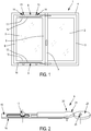
figure 1 est une représentation schématisée d'une fenêtre à deux vantaux dont le vantail semi-fixe est pourvu de dispositifs de verrouillage selon l'invention - la
figure 2 est une représentation schématisée et en perspective de la coopération entre une came destinée à équiper le vantail de service et la tringle d'un dispositif de verrouillage selon l'invention ; - la
figure 3 est une représentation schématisée en élévation et en coupe partielle du dispositif de verrouillage ; - la
figure 4 est une représentation schématisée, partielle et vue de dessous du dispositif de verrouillage ; - la
figure 5 illustre la coopération entre un organe de verrouillage et organe de verrouillage complémentaire pour repousser la tringle du dispositif de verrouillage depuis une position de blocage en direction de sa position de déverrouillage lors de l'ouverture ou de la fermeture du vantail semi-fixe.
- the
figure 1 is a diagrammatic representation of a window with two leaves, the semi-fixed leaf of which is provided with locking devices according to the invention - the
figure 2 is a schematic and perspective representation of the cooperation between a cam intended to equip the service leaf and the rod with a locking device according to the invention; - the
figure 3 is a diagrammatic representation in elevation and in partial section of the locking device; - the
figure 4 is a schematic, partial and bottom view of the locking device; - the
figure 5 illustrates the cooperation between a locking member and complementary locking member for pushing the rod of the locking device from a locking position towards its unlocking position during the opening or closing of the semi-fixed leaf.
Tel que représenté dans la
Comme de manière usuelle, ces vantaux 2, 3 sont montés pivotants autour d'axes verticaux à hauteur de leurs montants arrière 5, 6 sur ledit cadre dormant 4.As usual, these
Tandis que le vantail de service 2 vient en recouvrement au travers de son montant avant 7 sur le montant avant 8 du vantail semi-fixe 3.While the
L'invention concerne également un dispositif de verrouillage 9 pour le vantail semi-fixe 3, visible dans les
Ce dispositif de verrouillage 9 est prévu pour être implanté en feuillure de la traverse inférieure 10 et/ou supérieure 11 de ce vantail semi-fixe 3.This
Ainsi, ce dispositif de verrouillage 9 comporte une tringle 12 pourvue sur sa longueur d'au moins un organe de verrouillage 13, représenté sous forme d'un galet sur les figures, apte à coopérer avec un organe de verrouillage complémentaire 14, par exemple sous forme d'une gâche, implantée au niveau du cadre dormant 4.Thus, this
Cette tringle 12 est montée coulissante sur un support de fixation 15 qui peut substantiellement emprunter la forme d'une têtière 16. Ainsi, comme illustré sur les figures, la tringle 12 peut être montée coulissante à l'arrière de cette têtière 16 au moyen du ou des organes de verrouillage 13 fixes sur la tringle 12 au travers d'ouvertures oblongues 17 dans la têtière 16.This
Bien entendu, d'autres montages coulissants de la tringle 12 sur un tel support de fixation 15, notamment formé par une têtière 16 sont envisageables, sans que l'on s'écarte de l'objet de la présente invention.Of course, other sliding assemblies of the
A noter que cette tringle 12 est mobile en translation entre une position déverrouillée 18 et au moins une position de verrouillage 19 dans laquelle le ou les organes de verrouillage 13 sont amenés dans une position de verrouillage en coopération avec le ou les organes de verrouillage complémentaires 14.Note that this
Une extrémité 20 de la tringle 12 forme un organe de manœuvre au travers duquel cette tringle 12 peut, précisément, être repoussée dans au moins sa position de verrouillage 19.One
De manière substantielle, cette extrémité 20 de la tringle 12 peut être équipée d'un palpeur 21 sur lequel peut intervenir, plus aisément, cette action tentant à repousser la tringle 12 dans ladite position de verrouillage 19. Tout comme le ou les organes de verrouillage 13, le palpeur 21 peut équiper cette extrémité 20 de la tringle 12 au travers d'une ouverture oblongue 22 adaptée dans têtière 16 de manière à pouvoir s'étendre à l'avant de cette dernière.Substantially, this
Selon l'invention, le dispositif de verrouillage 9 équipant le vantail semi-fixe 3 et donc la tringle 12 de ce dispositif de verrouillage 9, est amené à être repoussé dans sa position de verrouillage 19 sous l'impulsion de la fermeture du vantail de service 2. Dans ce but, celui-ci comporte, avantageusement, une came 23 définie apte, lors de cette fermeture, à coopérer avec ladite extrémité 20, formant organe de manœuvre, de la tringle 12 du dispositif de verrouillage 9. Dans le mode de réalisation illustré, cette coopération intervient au travers du palpeur 21 définissant, substantiellement, cette extrémité 20 de ladite tringle 12.According to the invention, the
Selon un mode de réalisation avantageux de l'invention, le dispositif de verrouillage 9 et/ou la came 23 comporte des moyens de réglage 24 ; 25 permettant leur ajustement en position sur, selon le cas, le vantail semi-fixe 3 ou le vantail de service 2. De tels moyens de réglage 24, 25 permettent de palier aux tolérances de fabrication de la menuiserie ou encore au positionnement variable d'un vantail de service 2 par rapport à un vantail semi-fixe 3 dans un cadre dormant 4, voire au déréglage de ce positionnement du ou des vantaux 2, 3/According to an advantageous embodiment of the invention, the
Substantiellement, les moyens de réglage 25 associés à la came 23 peuvent se présenter sous forme d'un excentrique qui, par rotation, permet d'ajuster le profil de la came 23 aux contraintes précitées.Substantially, the adjustment means 25 associated with the
Quant aux moyens de réglages 24, ils peuvent consister en des moyens d'ajustement de la position du support de fixation 15 sur le vantail semi-fixe 3, donc en feuillure de la traverse inférieure 10 ou supérieure 11 de ce dernier.As for the adjustment means 24, they may consist of means for adjusting the position of the fixing
Toutefois, dans la suite de la description, il sera fait référence à un mode de réalisation préférentiel de ces moyens de réglage 24.However, in the remainder of the description, reference will be made to a preferred embodiment of these adjustment means 24.
Selon l'invention, la tringle 12 est soumise à des premiers moyens de rappel élastique 26 tendant à la repousser, en direction de sa position déverrouillée 18, notamment depuis sa position de verrouillage 19.According to the invention, the
Ces premiers moyens de rappel élastique 26 se présentent sous forme d'un ressort hélicoïdal 27 sur une extrémité 28 duquel prend appui la tringle 12, directement ou par l'intermédiaire du palpeur 21, de manière à provoquer la compression de ce ressort 27, maintenu en butée du côté de son extrémité opposée 29, lorsque ladite tringle 12 est repoussée dans sa direction de verrouillage 19.These first elastic return means 26 are in the form of a
Ce dispositif de verrouillage 9 comporte avantageusement des seconds moyens de rappel élastiques 30 repoussant la tringle 12 dans une position de blocage 31, entre la position déverrouillée 18 et la position de verrouillage 19.This
De manière substantielle, ces seconds moyens de rappel élastique 30 sont définis par le même ressort hélicoïdal 27 sur l'extrémité 29 duquel prend appui, directement ou par l'intermédiaire du palpeur 21, ladite tringle 12 pour comprimer ce ressort 27, maintenu en butée à son extrémité opposée 28, lorsque la tringle 12 est repoussée en position de déverrouillage 18.Substantially, these second elastic return means 30 are defined by the same
Selon un mode de réalisation avantageux, le ressort 27 est sensiblement précontraint entre deux parois d'extrémité 32, 33, d'un logement 34 ménagé dans un boîtier 35 associé au support de fixation 15, en l'occurrence la têtière 16 dans le mode de réalisation particulier, ici décrit. Par ailleurs, des doigts d'entraînement 36, 37 que comporte la tringle 12, ou le palpeur 21 dans le mode de réalisation illustré, viennent en appui sur les extrémités 28, 29 du ressort 27 au travers d'ouvertures appropriées dans les parois d'extrémité 32, 33 dudit boîtier 35.According to an advantageous embodiment, the
Ainsi, l'on comprend bien qu'en repoussant la tringle 12, que ce soit au travers de son extrémité 20 ou, comme cela sera décrit ci-après, par l'intermédiaire du ou des organes de verrouillage 13, dans l'une ou l'autre direction de déverrouillage ou de verrouillage, partant de la position de blocage 31, il en résulte la compression du ressort 27 dans son logement 34.Thus, it is clearly understood that by pushing back the
Au vu de la description qui précède et des dessins ci-joints, il apparait que la tringle 12 est maintenue dans la position de blocage 31 sous l'influence antagoniste des premiers 26 et seconds 30 moyens de rappel élastique substantiellement définis par le ressort 27In view of the above description and the accompanying drawings, it appears that the
Précisément, selon l'invention dans cette position de blocage 31, les organes de verrouillage 13 se situent eux-mêmes dans une position de blocage 38 en relation avec des organes de verrouillage complémentaires 14, ceci entre une position de verrouillage et une position déverrouillée. Dans cette position de blocage 38, les organes de verrouillage 13 sont définis aptes, en coopération avec les organes de verrouillage complémentaires 14, à assurer une fonction de maintien du vantail semi-fixe 3 refermé sur le cadre dormant 4.Specifically, according to the invention in this
Par ailleurs, toujours dans cette position de blocage 38 les organes de verrouillage complémentaires 14, en coopération avec lesdits organes de verrouillage 13, repoussent le ou les organes de verrouillage 13 en direction du déverrouillage sous l'action d'un effort exercé entre un tel organe de verrouillage complémentaire 14 et un organe de verrouillage 13 perpendiculaire à la direction de déplacement de la tringle 12.Furthermore, still in this
Cette interaction intervient à la commande d'ouverture du vantail semi-fixe 3 et au moment de refermer celui-ci sur le cadre dormant 4, donc que ce soit pour dégager le ou les organes de verrouillage 13 de leur organe de verrouillage complémentaire 14 ou de les engager dans ces derniers.This interaction occurs when the
Ainsi, dans le cadre d'une coopération entre organe de verrouillage 13 et organes de verrouillage complémentaires 14, sous forme d'un galet et d'une gâche comme illustré dans la
Pour en revenir à présent aux moyens de réglages 24 évoqués plus haut, ceux-ci consiste avantageusement en un montage coulissant du boitier 35, contenant le ressort 27, sur le support de fixation 15 correspondant, ici, à la têtière 16. Ces moyens 24 sont encore complétés par un organe d'ajustement 41 de la position de ce boitier 35 sur ledit support de fixation 15.Coming back now to the adjustment means 24 mentioned above, these advantageously consist of a sliding assembly of the
A titre d'exemple et comme représenté, cet organe d'ajustement 41 peut consister en une vis de réglage 42 en coopération avec la têtière 16 et en prise avec un trou taraudé 43 dans le boitier 35. En particulier, la têtière 16 peut être pourvue, à son extrémité d'un retour 44 traversé d'un trou pour le passage de la vis 42. Celle-ci peut être accessible en feuillure de traverse inférieure 10 ou selon le cas supérieure 11 du vantail semi-fixe 3, sensiblement dans l'angle avec le montant avant 8 de ce dernier.By way of example and as shown, this
Claims (8)
- A locking device for a semi-fixed door or window (1) leaf (3) mounted pivoting on a frame (4) and cooperating, in the closed position of said door or window (1), with a movable leaf (2) covering it, including a control rod (12) provided, over its length, with at least one locking member (13) able to cooperate with a complementary locking member (14), in the form of a roller and a strike, this control rod (12) being mounted sliding on a fastening support (15), between an unlocked position (18) and at least one locking position (19), said control rod (12) further including an end (20) forming a maneuvering member to push it into the locked position (19) in which the locking member(s) (13) are each able to cooperate with a complementary locking member (14), characterized in that it includes first resilient return means (26) tending to push the control rod (12) back toward its unlocked position (18) and second resilient return means (30) pushing this control rod (12) into a blocking position (31), between the unlocked position (18) and the locked position (19).
- The locking device according to claim 1, characterized in that the control rod (12) is mounted sliding behind a fastening support (15) in the form of a selvedge (16).
- The locking device according to claim 1 or 2, characterized in that the end (20) of the control rod (12) forming the maneuvering member is equipped with a feeler (21) able to cooperate with a cam (23).
- The locking device according to any one of the preceding claims, characterized in that the first (26) and second resilient return means (30) are defined by a spring (27) mounted substantially prestressed between two end walls (32, 33), with a housing (34) arranged in a casing (35) associated with the fastening support (15), the control rod (12) including driving fingers (36, 37) bearing on the ends (28, 29) of said spring (27) through appropriate openings in the end walls (32, 33) of said casing (35).
- The locking device according to any one of the preceding claims, characterized in that through the first (26) and second (30) resilient return means, the control rod (12) is kept in the blocking position (31) in which the locking members (13) are in turn located in a blocking position (38) in relation to the complementary locking members (14), between a locked position and an unlocked position.
- The locking device according to claim 5, characterized in that in the blocking position (38), the locking members (13) are defined to be able, in cooperation with the complementary locking members (14), to perform a function of keeping the semi-fixed leaf (3) closed on the frame (4).
- The locking device according to claim 5 or 6, characterized in that in the blocking position (38), the complementary locking members (14), in cooperation with said locking members (13), push the latter back toward the unlocked position under the action of a force exerted between one such complementary locking member (14) and a locking member (13) perpendicular to the movement direction of the control rod (12).
- A door or window (1) including at least two pivoting leaves including a service leaf (2) covering, in the closed position of the door or window (1), a semi-fixed leaf (3) provided, in the rebate of its upper (11) and/or lower (10) horizontal crosspiece, with a locking device (9) according to any one of the preceding claims, including a control rod (12) provided, over its length, with at least one locking member (13) and mounted sliding on a fastening support (15), said control rod (12) including an end (20) forming a maneuvering member with which a cam (23) equipping the service leaf (2) is brought to cooperate in order, during the closing of said service leaf (2), to push said control rod (12) back into at least one locked position (19) against the action of first (26) and second (30) resilient return means, in which locked position (19) the locking members (13) are brought into at least one locked position in cooperation with a complementary locking member (14) equipping the frame (4) of said door or window (1).
Priority Applications (1)
| Application Number | Priority Date | Filing Date | Title |
|---|---|---|---|
| PL15155594T PL2907947T3 (en) | 2014-02-18 | 2015-02-18 | Locking device for semi-fixed door or window leaf |
Applications Claiming Priority (2)
| Application Number | Priority Date | Filing Date | Title |
|---|---|---|---|
| FR1451298A FR3017644A1 (en) | 2014-02-18 | 2014-02-18 | LOCKING DEVICE FOR SEMI-FIXED DOOR OF DOOR OR WINDOW. |
| FR1451956A FR3017645B1 (en) | 2014-02-18 | 2014-03-10 | LOCKING DEVICE FOR SEMI-FIXED DOOR OR WINDOW LEAF |
Publications (2)
| Publication Number | Publication Date |
|---|---|
| EP2907947A1 EP2907947A1 (en) | 2015-08-19 |
| EP2907947B1 true EP2907947B1 (en) | 2021-08-18 |
Family
ID=52472257
Family Applications (1)
| Application Number | Title | Priority Date | Filing Date |
|---|---|---|---|
| EP15155594.3A Active EP2907947B1 (en) | 2014-02-18 | 2015-02-18 | Locking device for semi-fixed door or window leaf |
Country Status (3)
| Country | Link |
|---|---|
| EP (1) | EP2907947B1 (en) |
| FR (1) | FR3017645B1 (en) |
| PL (1) | PL2907947T3 (en) |
Family Cites Families (6)
| Publication number | Priority date | Publication date | Assignee | Title |
|---|---|---|---|---|
| DE10011991A1 (en) * | 1999-08-04 | 2001-09-13 | Siegenia Frank Kg | Locking system for a window/door with three or more panels and without a center post has an inner bar with a bolt and a closure to secure the center panel frame to a flanking panel |
| ITMI20051386A1 (en) * | 2005-07-20 | 2007-01-21 | New Art System S R L | SECURITY LOCK FOR DOORS AND WINDOWS |
| TWM364751U (en) * | 2008-12-30 | 2009-09-11 | Thase Entpr Co Ltd | Hidden vertical bolt having automatic mechanism |
| FR2959769B1 (en) | 2010-05-10 | 2013-02-15 | Grosfillex Sas | LOCKING DEVICE FOR SEMI-FIXED VANTAIL |
| FR2981107B1 (en) * | 2011-10-10 | 2013-11-29 | Grosfillex Sas | RETENTION DEVICE FOR SEMI-FIXED VANTAIL |
| US8562032B1 (en) * | 2012-05-21 | 2013-10-22 | I-Tek Metal Mfg. Co., Ltd. | Latch assembly with automatic locking function |
-
2014
- 2014-03-10 FR FR1451956A patent/FR3017645B1/en active Active
-
2015
- 2015-02-18 PL PL15155594T patent/PL2907947T3/en unknown
- 2015-02-18 EP EP15155594.3A patent/EP2907947B1/en active Active
Also Published As
| Publication number | Publication date |
|---|---|
| PL2907947T3 (en) | 2021-12-20 |
| FR3017645B1 (en) | 2021-06-11 |
| EP2907947A1 (en) | 2015-08-19 |
| FR3017645A1 (en) | 2015-08-21 |
Similar Documents
| Publication | Publication Date | Title |
|---|---|---|
| FR2952107A1 (en) | WINDOW-FORMING CABINET WITH LATCH FOR AT LEAST ONE SLIDING GLASS | |
| EP0952284A1 (en) | Locking device for a sliding wing | |
| EP1674647A2 (en) | Driving device for closures of the shutter or gate type, or similar | |
| EP2907947B1 (en) | Locking device for semi-fixed door or window leaf | |
| FR3001754A1 (en) | DEVICE FOR LOCKING A MOBILE PANEL IN TRANSLATION AND OCCULTATION DEVICE COMPRISING SUCH A DEVICE. | |
| EP3816373B1 (en) | Device and method for locking a sliding door | |
| EP2770145A1 (en) | Strike for T-shaped locking button | |
| EP1564354B1 (en) | Control and locking system, particularly for espagnolette, for the opening and closing operation of a door | |
| EP2063053A2 (en) | Espagnolette or espagnolette-lock | |
| FR3017644A1 (en) | LOCKING DEVICE FOR SEMI-FIXED DOOR OF DOOR OR WINDOW. | |
| FR2907484A1 (en) | Sliding casement locking device for e.g. picture window, has hook integrated to support parts that are fixed on rear surface of rod, where rod is mounted on front wall by inserting support parts across opening that is arranged in front wall | |
| EP2273045B1 (en) | Espagnolette lock for door, window or similar | |
| FR2982305A1 (en) | Lock for locking door leaf of e.g. door window, has thrust unit arranged on trajectory of control unit that is movable with respect to door leaf, and control unit movably arranged to move when door leaf is locked by user | |
| FR2926579A1 (en) | Reinforced safety lock for door, has case including blocking piece to be rotated from restraint position in which piece retains finger in retracted position to released position in which finger is moved to carry piece in extension position | |
| EP3530851B1 (en) | Locking system for a sectional door with lateral movement | |
| FR2927116A1 (en) | ANTI-LIFTING DEVICE FOR CLOSURE SYSTEM OCCULTATION ELEMENT, SHUTTER TYPE, STORE, MOSQUITO OR SIMILAR. | |
| FR2977621A3 (en) | Catch closing device for e.g. two leafs door used to close opening in wall, has cam integrated in retaining groove so as to be engaged in notch or released by displacement of locking element without releasing edge of hinge plate from groove | |
| EP1878862B1 (en) | Locking mechanism for a window sash | |
| EP1475497A1 (en) | Lock bolt for wing of a door or window | |
| FR3057010A1 (en) | SLIDING COMPONENT | |
| FR2907483A1 (en) | Sliding casement locking device for e.g. picture window, has hook integrated to support pieces fixed on rear surface of rod, where rod is mounted on front wall by inserting support pieces in opening provided in front wall | |
| EP3101203B1 (en) | Locking device and opening comprising such a device | |
| FR2821877A1 (en) | Cremona lock, for window or door bay divider, includes lock with engaging roller cooperating with latching blade | |
| EP2636828B1 (en) | Lock fitting of the espagnolette type for a door- or window-wing | |
| EP4190998A1 (en) | Device for holding a wing |
Legal Events
| Date | Code | Title | Description |
|---|---|---|---|
| PUAI | Public reference made under article 153(3) epc to a published international application that has entered the european phase |
Free format text: ORIGINAL CODE: 0009012 |
|
| AK | Designated contracting states |
Kind code of ref document: A1 Designated state(s): AL AT BE BG CH CY CZ DE DK EE ES FI FR GB GR HR HU IE IS IT LI LT LU LV MC MK MT NL NO PL PT RO RS SE SI SK SM TR |
|
| AX | Request for extension of the european patent |
Extension state: BA ME |
|
| STAA | Information on the status of an ep patent application or granted ep patent |
Free format text: STATUS: REQUEST FOR EXAMINATION WAS MADE |
|
| 17P | Request for examination filed |
Effective date: 20160211 |
|
| RBV | Designated contracting states (corrected) |
Designated state(s): AL AT BE BG CH CY CZ DE DK EE ES FI FR GB GR HR HU IE IS IT LI LT LU LV MC MK MT NL NO PL PT RO RS SE SI SK SM TR |
|
| GRAP | Despatch of communication of intention to grant a patent |
Free format text: ORIGINAL CODE: EPIDOSNIGR1 |
|
| STAA | Information on the status of an ep patent application or granted ep patent |
Free format text: STATUS: GRANT OF PATENT IS INTENDED |
|
| INTG | Intention to grant announced |
Effective date: 20210316 |
|
| GRAS | Grant fee paid |
Free format text: ORIGINAL CODE: EPIDOSNIGR3 |
|
| GRAA | (expected) grant |
Free format text: ORIGINAL CODE: 0009210 |
|
| STAA | Information on the status of an ep patent application or granted ep patent |
Free format text: STATUS: THE PATENT HAS BEEN GRANTED |
|
| AK | Designated contracting states |
Kind code of ref document: B1 Designated state(s): AL AT BE BG CH CY CZ DE DK EE ES FI FR GB GR HR HU IE IS IT LI LT LU LV MC MK MT NL NO PL PT RO RS SE SI SK SM TR |
|
| REG | Reference to a national code |
Ref country code: GB Ref legal event code: FG4D Free format text: NOT ENGLISH |
|
| REG | Reference to a national code |
Ref country code: CH Ref legal event code: EP |
|
| REG | Reference to a national code |
Ref country code: DE Ref legal event code: R096 Ref document number: 602015072329 Country of ref document: DE |
|
| REG | Reference to a national code |
Ref country code: IE Ref legal event code: FG4D Free format text: LANGUAGE OF EP DOCUMENT: FRENCH Ref country code: AT Ref legal event code: REF Ref document number: 1421793 Country of ref document: AT Kind code of ref document: T Effective date: 20210915 |
|
| REG | Reference to a national code |
Ref country code: LT Ref legal event code: MG9D |
|
| REG | Reference to a national code |
Ref country code: NL Ref legal event code: MP Effective date: 20210818 |
|
| PG25 | Lapsed in a contracting state [announced via postgrant information from national office to epo] |
Ref country code: SE Free format text: LAPSE BECAUSE OF FAILURE TO SUBMIT A TRANSLATION OF THE DESCRIPTION OR TO PAY THE FEE WITHIN THE PRESCRIBED TIME-LIMIT Effective date: 20210818 Ref country code: RS Free format text: LAPSE BECAUSE OF FAILURE TO SUBMIT A TRANSLATION OF THE DESCRIPTION OR TO PAY THE FEE WITHIN THE PRESCRIBED TIME-LIMIT Effective date: 20210818 Ref country code: HR Free format text: LAPSE BECAUSE OF FAILURE TO SUBMIT A TRANSLATION OF THE DESCRIPTION OR TO PAY THE FEE WITHIN THE PRESCRIBED TIME-LIMIT Effective date: 20210818 Ref country code: LT Free format text: LAPSE BECAUSE OF FAILURE TO SUBMIT A TRANSLATION OF THE DESCRIPTION OR TO PAY THE FEE WITHIN THE PRESCRIBED TIME-LIMIT Effective date: 20210818 Ref country code: BG Free format text: LAPSE BECAUSE OF FAILURE TO SUBMIT A TRANSLATION OF THE DESCRIPTION OR TO PAY THE FEE WITHIN THE PRESCRIBED TIME-LIMIT Effective date: 20211118 Ref country code: NO Free format text: LAPSE BECAUSE OF FAILURE TO SUBMIT A TRANSLATION OF THE DESCRIPTION OR TO PAY THE FEE WITHIN THE PRESCRIBED TIME-LIMIT Effective date: 20211118 Ref country code: PT Free format text: LAPSE BECAUSE OF FAILURE TO SUBMIT A TRANSLATION OF THE DESCRIPTION OR TO PAY THE FEE WITHIN THE PRESCRIBED TIME-LIMIT Effective date: 20211220 Ref country code: ES Free format text: LAPSE BECAUSE OF FAILURE TO SUBMIT A TRANSLATION OF THE DESCRIPTION OR TO PAY THE FEE WITHIN THE PRESCRIBED TIME-LIMIT Effective date: 20210818 Ref country code: FI Free format text: LAPSE BECAUSE OF FAILURE TO SUBMIT A TRANSLATION OF THE DESCRIPTION OR TO PAY THE FEE WITHIN THE PRESCRIBED TIME-LIMIT Effective date: 20210818 |
|
| PG25 | Lapsed in a contracting state [announced via postgrant information from national office to epo] |
Ref country code: LV Free format text: LAPSE BECAUSE OF FAILURE TO SUBMIT A TRANSLATION OF THE DESCRIPTION OR TO PAY THE FEE WITHIN THE PRESCRIBED TIME-LIMIT Effective date: 20210818 Ref country code: GR Free format text: LAPSE BECAUSE OF FAILURE TO SUBMIT A TRANSLATION OF THE DESCRIPTION OR TO PAY THE FEE WITHIN THE PRESCRIBED TIME-LIMIT Effective date: 20211119 |
|
| PG25 | Lapsed in a contracting state [announced via postgrant information from national office to epo] |
Ref country code: NL Free format text: LAPSE BECAUSE OF FAILURE TO SUBMIT A TRANSLATION OF THE DESCRIPTION OR TO PAY THE FEE WITHIN THE PRESCRIBED TIME-LIMIT Effective date: 20210818 |
|
| PG25 | Lapsed in a contracting state [announced via postgrant information from national office to epo] |
Ref country code: DK Free format text: LAPSE BECAUSE OF FAILURE TO SUBMIT A TRANSLATION OF THE DESCRIPTION OR TO PAY THE FEE WITHIN THE PRESCRIBED TIME-LIMIT Effective date: 20210818 |
|
| REG | Reference to a national code |
Ref country code: DE Ref legal event code: R097 Ref document number: 602015072329 Country of ref document: DE |
|
| PG25 | Lapsed in a contracting state [announced via postgrant information from national office to epo] |
Ref country code: SM Free format text: LAPSE BECAUSE OF FAILURE TO SUBMIT A TRANSLATION OF THE DESCRIPTION OR TO PAY THE FEE WITHIN THE PRESCRIBED TIME-LIMIT Effective date: 20210818 Ref country code: SK Free format text: LAPSE BECAUSE OF FAILURE TO SUBMIT A TRANSLATION OF THE DESCRIPTION OR TO PAY THE FEE WITHIN THE PRESCRIBED TIME-LIMIT Effective date: 20210818 Ref country code: RO Free format text: LAPSE BECAUSE OF FAILURE TO SUBMIT A TRANSLATION OF THE DESCRIPTION OR TO PAY THE FEE WITHIN THE PRESCRIBED TIME-LIMIT Effective date: 20210818 Ref country code: EE Free format text: LAPSE BECAUSE OF FAILURE TO SUBMIT A TRANSLATION OF THE DESCRIPTION OR TO PAY THE FEE WITHIN THE PRESCRIBED TIME-LIMIT Effective date: 20210818 Ref country code: CZ Free format text: LAPSE BECAUSE OF FAILURE TO SUBMIT A TRANSLATION OF THE DESCRIPTION OR TO PAY THE FEE WITHIN THE PRESCRIBED TIME-LIMIT Effective date: 20210818 Ref country code: AL Free format text: LAPSE BECAUSE OF FAILURE TO SUBMIT A TRANSLATION OF THE DESCRIPTION OR TO PAY THE FEE WITHIN THE PRESCRIBED TIME-LIMIT Effective date: 20210818 |
|
| PLBE | No opposition filed within time limit |
Free format text: ORIGINAL CODE: 0009261 |
|
| STAA | Information on the status of an ep patent application or granted ep patent |
Free format text: STATUS: NO OPPOSITION FILED WITHIN TIME LIMIT |
|
| 26N | No opposition filed |
Effective date: 20220519 |
|
| PG25 | Lapsed in a contracting state [announced via postgrant information from national office to epo] |
Ref country code: IT Free format text: LAPSE BECAUSE OF FAILURE TO SUBMIT A TRANSLATION OF THE DESCRIPTION OR TO PAY THE FEE WITHIN THE PRESCRIBED TIME-LIMIT Effective date: 20210818 |
|
| PG25 | Lapsed in a contracting state [announced via postgrant information from national office to epo] |
Ref country code: SI Free format text: LAPSE BECAUSE OF FAILURE TO SUBMIT A TRANSLATION OF THE DESCRIPTION OR TO PAY THE FEE WITHIN THE PRESCRIBED TIME-LIMIT Effective date: 20210818 |
|
| PG25 | Lapsed in a contracting state [announced via postgrant information from national office to epo] |
Ref country code: MC Free format text: LAPSE BECAUSE OF FAILURE TO SUBMIT A TRANSLATION OF THE DESCRIPTION OR TO PAY THE FEE WITHIN THE PRESCRIBED TIME-LIMIT Effective date: 20210818 |
|
| REG | Reference to a national code |
Ref country code: CH Ref legal event code: PL |
|
| REG | Reference to a national code |
Ref country code: BE Ref legal event code: MM Effective date: 20220228 |
|
| GBPC | Gb: european patent ceased through non-payment of renewal fee |
Effective date: 20220218 |
|
| PG25 | Lapsed in a contracting state [announced via postgrant information from national office to epo] |
Ref country code: LU Free format text: LAPSE BECAUSE OF NON-PAYMENT OF DUE FEES Effective date: 20220218 |
|
| PG25 | Lapsed in a contracting state [announced via postgrant information from national office to epo] |
Ref country code: LI Free format text: LAPSE BECAUSE OF NON-PAYMENT OF DUE FEES Effective date: 20220228 Ref country code: IE Free format text: LAPSE BECAUSE OF NON-PAYMENT OF DUE FEES Effective date: 20220218 Ref country code: GB Free format text: LAPSE BECAUSE OF NON-PAYMENT OF DUE FEES Effective date: 20220218 Ref country code: CH Free format text: LAPSE BECAUSE OF NON-PAYMENT OF DUE FEES Effective date: 20220228 |
|
| PG25 | Lapsed in a contracting state [announced via postgrant information from national office to epo] |
Ref country code: BE Free format text: LAPSE BECAUSE OF NON-PAYMENT OF DUE FEES Effective date: 20220228 |
|
| REG | Reference to a national code |
Ref country code: AT Ref legal event code: UEP Ref document number: 1421793 Country of ref document: AT Kind code of ref document: T Effective date: 20210818 |
|
| PGFP | Annual fee paid to national office [announced via postgrant information from national office to epo] |
Ref country code: FR Payment date: 20230221 Year of fee payment: 9 |
|
| PGFP | Annual fee paid to national office [announced via postgrant information from national office to epo] |
Ref country code: PL Payment date: 20230119 Year of fee payment: 9 |
|
| P01 | Opt-out of the competence of the unified patent court (upc) registered |
Effective date: 20230720 |
|
| PG25 | Lapsed in a contracting state [announced via postgrant information from national office to epo] |
Ref country code: HU Free format text: LAPSE BECAUSE OF FAILURE TO SUBMIT A TRANSLATION OF THE DESCRIPTION OR TO PAY THE FEE WITHIN THE PRESCRIBED TIME-LIMIT; INVALID AB INITIO Effective date: 20150218 |
|
| PGFP | Annual fee paid to national office [announced via postgrant information from national office to epo] |
Ref country code: AT Payment date: 20240220 Year of fee payment: 10 |
|
| PG25 | Lapsed in a contracting state [announced via postgrant information from national office to epo] |
Ref country code: MK Free format text: LAPSE BECAUSE OF FAILURE TO SUBMIT A TRANSLATION OF THE DESCRIPTION OR TO PAY THE FEE WITHIN THE PRESCRIBED TIME-LIMIT Effective date: 20210818 Ref country code: CY Free format text: LAPSE BECAUSE OF FAILURE TO SUBMIT A TRANSLATION OF THE DESCRIPTION OR TO PAY THE FEE WITHIN THE PRESCRIBED TIME-LIMIT Effective date: 20210818 |
|
| PGFP | Annual fee paid to national office [announced via postgrant information from national office to epo] |
Ref country code: DE Payment date: 20240219 Year of fee payment: 10 |