EP2832301B1 - Sonde und diagnostische bildgebungsvorrichtung - Google Patents
Sonde und diagnostische bildgebungsvorrichtung Download PDFInfo
- Publication number
- EP2832301B1 EP2832301B1 EP13768700.0A EP13768700A EP2832301B1 EP 2832301 B1 EP2832301 B1 EP 2832301B1 EP 13768700 A EP13768700 A EP 13768700A EP 2832301 B1 EP2832301 B1 EP 2832301B1
- Authority
- EP
- European Patent Office
- Prior art keywords
- transmitting
- probe
- receiving unit
- disposed
- ultrasound
- Prior art date
- Legal status (The legal status is an assumption and is not a legal conclusion. Google has not performed a legal analysis and makes no representation as to the accuracy of the status listed.)
- Active
Links
- 239000000523 sample Substances 0.000 title claims description 79
- 238000002059 diagnostic imaging Methods 0.000 title 1
- 238000002604 ultrasonography Methods 0.000 claims description 84
- 230000003287 optical effect Effects 0.000 claims description 83
- 238000003384 imaging method Methods 0.000 claims description 44
- 238000003745 diagnosis Methods 0.000 claims description 24
- 238000010586 diagram Methods 0.000 description 20
- 230000005540 biological transmission Effects 0.000 description 19
- 239000000835 fiber Substances 0.000 description 17
- 238000012545 processing Methods 0.000 description 17
- 238000012014 optical coherence tomography Methods 0.000 description 15
- 238000002608 intravascular ultrasound Methods 0.000 description 13
- 230000004048 modification Effects 0.000 description 12
- 238000012986 modification Methods 0.000 description 12
- 210000004204 blood vessel Anatomy 0.000 description 9
- 239000013307 optical fiber Substances 0.000 description 8
- 244000208734 Pisonia aculeata Species 0.000 description 7
- 238000000034 method Methods 0.000 description 7
- 238000005259 measurement Methods 0.000 description 6
- 239000002184 metal Substances 0.000 description 4
- 230000008901 benefit Effects 0.000 description 3
- 230000008569 process Effects 0.000 description 3
- 238000010408 sweeping Methods 0.000 description 3
- 238000006243 chemical reaction Methods 0.000 description 2
- 230000008878 coupling Effects 0.000 description 2
- 238000010168 coupling process Methods 0.000 description 2
- 238000005859 coupling reaction Methods 0.000 description 2
- 230000007246 mechanism Effects 0.000 description 2
- 238000005070 sampling Methods 0.000 description 2
- 229910001220 stainless steel Inorganic materials 0.000 description 2
- 230000001360 synchronised effect Effects 0.000 description 2
- 206010003210 Arteriosclerosis Diseases 0.000 description 1
- 208000011775 arteriosclerosis disease Diseases 0.000 description 1
- 238000005452 bending Methods 0.000 description 1
- 230000008859 change Effects 0.000 description 1
- 238000012937 correction Methods 0.000 description 1
- 230000001419 dependent effect Effects 0.000 description 1
- 230000000694 effects Effects 0.000 description 1
- 238000001746 injection moulding Methods 0.000 description 1
- 230000002452 interceptive effect Effects 0.000 description 1
- 230000003902 lesion Effects 0.000 description 1
- 230000000704 physical effect Effects 0.000 description 1
- 230000002980 postoperative effect Effects 0.000 description 1
- 239000000843 powder Substances 0.000 description 1
- 230000001012 protector Effects 0.000 description 1
- 230000002787 reinforcement Effects 0.000 description 1
- 239000004065 semiconductor Substances 0.000 description 1
- 239000000243 solution Substances 0.000 description 1
- 239000010935 stainless steel Substances 0.000 description 1
Images


Classifications
-
- A—HUMAN NECESSITIES
- A61—MEDICAL OR VETERINARY SCIENCE; HYGIENE
- A61B—DIAGNOSIS; SURGERY; IDENTIFICATION
- A61B8/00—Diagnosis using ultrasonic, sonic or infrasonic waves
- A61B8/44—Constructional features of the ultrasonic, sonic or infrasonic diagnostic device
- A61B8/4444—Constructional features of the ultrasonic, sonic or infrasonic diagnostic device related to the probe
- A61B8/4461—Features of the scanning mechanism, e.g. for moving the transducer within the housing of the probe
- A61B8/4466—Features of the scanning mechanism, e.g. for moving the transducer within the housing of the probe involving deflection of the probe
-
- A—HUMAN NECESSITIES
- A61—MEDICAL OR VETERINARY SCIENCE; HYGIENE
- A61B—DIAGNOSIS; SURGERY; IDENTIFICATION
- A61B5/00—Measuring for diagnostic purposes; Identification of persons
- A61B5/0033—Features or image-related aspects of imaging apparatus classified in A61B5/00, e.g. for MRI, optical tomography or impedance tomography apparatus; arrangements of imaging apparatus in a room
- A61B5/0035—Features or image-related aspects of imaging apparatus classified in A61B5/00, e.g. for MRI, optical tomography or impedance tomography apparatus; arrangements of imaging apparatus in a room adapted for acquisition of images from more than one imaging mode, e.g. combining MRI and optical tomography
-
- A—HUMAN NECESSITIES
- A61—MEDICAL OR VETERINARY SCIENCE; HYGIENE
- A61B—DIAGNOSIS; SURGERY; IDENTIFICATION
- A61B5/00—Measuring for diagnostic purposes; Identification of persons
- A61B5/0059—Measuring for diagnostic purposes; Identification of persons using light, e.g. diagnosis by transillumination, diascopy, fluorescence
- A61B5/0062—Arrangements for scanning
- A61B5/0066—Optical coherence imaging
-
- A—HUMAN NECESSITIES
- A61—MEDICAL OR VETERINARY SCIENCE; HYGIENE
- A61B—DIAGNOSIS; SURGERY; IDENTIFICATION
- A61B5/00—Measuring for diagnostic purposes; Identification of persons
- A61B5/0059—Measuring for diagnostic purposes; Identification of persons using light, e.g. diagnosis by transillumination, diascopy, fluorescence
- A61B5/0082—Measuring for diagnostic purposes; Identification of persons using light, e.g. diagnosis by transillumination, diascopy, fluorescence adapted for particular medical purposes
- A61B5/0084—Measuring for diagnostic purposes; Identification of persons using light, e.g. diagnosis by transillumination, diascopy, fluorescence adapted for particular medical purposes for introduction into the body, e.g. by catheters
-
- A—HUMAN NECESSITIES
- A61—MEDICAL OR VETERINARY SCIENCE; HYGIENE
- A61B—DIAGNOSIS; SURGERY; IDENTIFICATION
- A61B5/00—Measuring for diagnostic purposes; Identification of persons
- A61B5/68—Arrangements of detecting, measuring or recording means, e.g. sensors, in relation to patient
- A61B5/6846—Arrangements of detecting, measuring or recording means, e.g. sensors, in relation to patient specially adapted to be brought in contact with an internal body part, i.e. invasive
- A61B5/6847—Arrangements of detecting, measuring or recording means, e.g. sensors, in relation to patient specially adapted to be brought in contact with an internal body part, i.e. invasive mounted on an invasive device
- A61B5/6852—Catheters
-
- A—HUMAN NECESSITIES
- A61—MEDICAL OR VETERINARY SCIENCE; HYGIENE
- A61B—DIAGNOSIS; SURGERY; IDENTIFICATION
- A61B8/00—Diagnosis using ultrasonic, sonic or infrasonic waves
- A61B8/12—Diagnosis using ultrasonic, sonic or infrasonic waves in body cavities or body tracts, e.g. by using catheters
-
- A—HUMAN NECESSITIES
- A61—MEDICAL OR VETERINARY SCIENCE; HYGIENE
- A61B—DIAGNOSIS; SURGERY; IDENTIFICATION
- A61B8/00—Diagnosis using ultrasonic, sonic or infrasonic waves
- A61B8/44—Constructional features of the ultrasonic, sonic or infrasonic diagnostic device
- A61B8/4444—Constructional features of the ultrasonic, sonic or infrasonic diagnostic device related to the probe
- A61B8/445—Details of catheter construction
-
- A—HUMAN NECESSITIES
- A61—MEDICAL OR VETERINARY SCIENCE; HYGIENE
- A61B—DIAGNOSIS; SURGERY; IDENTIFICATION
- A61B8/00—Diagnosis using ultrasonic, sonic or infrasonic waves
- A61B8/44—Constructional features of the ultrasonic, sonic or infrasonic diagnostic device
- A61B8/4444—Constructional features of the ultrasonic, sonic or infrasonic diagnostic device related to the probe
- A61B8/4461—Features of the scanning mechanism, e.g. for moving the transducer within the housing of the probe
-
- A—HUMAN NECESSITIES
- A61—MEDICAL OR VETERINARY SCIENCE; HYGIENE
- A61B—DIAGNOSIS; SURGERY; IDENTIFICATION
- A61B8/00—Diagnosis using ultrasonic, sonic or infrasonic waves
- A61B8/44—Constructional features of the ultrasonic, sonic or infrasonic diagnostic device
- A61B8/4483—Constructional features of the ultrasonic, sonic or infrasonic diagnostic device characterised by features of the ultrasound transducer
- A61B8/4494—Constructional features of the ultrasonic, sonic or infrasonic diagnostic device characterised by features of the ultrasound transducer characterised by the arrangement of the transducer elements
-
- A—HUMAN NECESSITIES
- A61—MEDICAL OR VETERINARY SCIENCE; HYGIENE
- A61B—DIAGNOSIS; SURGERY; IDENTIFICATION
- A61B8/00—Diagnosis using ultrasonic, sonic or infrasonic waves
- A61B8/52—Devices using data or image processing specially adapted for diagnosis using ultrasonic, sonic or infrasonic waves
- A61B8/5207—Devices using data or image processing specially adapted for diagnosis using ultrasonic, sonic or infrasonic waves involving processing of raw data to produce diagnostic data, e.g. for generating an image
-
- A—HUMAN NECESSITIES
- A61—MEDICAL OR VETERINARY SCIENCE; HYGIENE
- A61B—DIAGNOSIS; SURGERY; IDENTIFICATION
- A61B8/00—Diagnosis using ultrasonic, sonic or infrasonic waves
- A61B8/54—Control of the diagnostic device
Definitions
- the present invention relates to a probe and an imaging apparatus for diagnosis.
- imaging apparatuses for diagnosis have been widely used for performing diagnoses of arteriosclerosis, preoperative diagnoses during intra-vascular treatment using a high-performance catheter such as a balloon catheter or a stent, and checking postoperative results.
- the imaging apparatus for diagnosis includes an intra-vascular ultra sound diagnostic apparatus (IVUS) and an optical coherence tomography diagnostic apparatus (OCT) and the like, each of which has characteristics different from each other.
- IVUS intra-vascular ultra sound diagnostic apparatus
- OCT optical coherence tomography diagnostic apparatus
- an imaging apparatus for diagnosis has been proposed in which the function of the IVUS and the function of the OCT are combined (for example, see PTL 1). According to such an imaging apparatus for diagnosis, it is possible to generate a tomographic image taking advantage of the characteristics of the IVUS which can measure up to a high depth region and advantage of the characteristics of the OCT which can measure an area with a high resolution.
- a technique of increasing obtainable tomographic images for each unit time that is, image information is acquired at a high speed
- by radiating the same signals (energy) in a plurality of directions for example, see PTL 2.
- transmitting and receiving units transmit and receive ultrasound or light while causing a probe to perform a rotary operation and an axial-direction operation inside a blood vessel, and thereby the imaging apparatus generates tomographic images. Therefore, when the rotary operation and the axial-direction operation are performed, if a transmitting and receiving unit for IVUS and a transmitting and receiving unit for OCT are disposed to be inclined in different directions with respect to a direction orthogonal to the direction of the rotary axis (that is, if one is disposed to be inclined to a distal side of the probe and the other is disposed to be inclined to a proximal side of the probe), angles of cross sections cut on the ultrasonic tomographic image and the optical tomographic image are different.
- the present invention has been made taking the aforementioned problems into consideration, and aims to provide a technique of matching observation angles in an imaging apparatus for diagnosis that can generate respective tomographic images by using a plurality of transmitting and receiving units.
- an aspect of the invention is to provide a probe as defined in claim 1.
- Preferred embodiments are defined in the dependent claims.
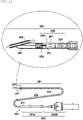
- Fig. 1 is a diagram illustrating an example of an entire configuration of an imaging apparatus for diagnosis 100 according to an embodiment of the present invention.
- the imaging apparatus for diagnosis 100 is configured to include a function of IVUS and a function of OCT. That is, the imaging apparatus for diagnosis 100 generates a tomographic image that utilizes both the characteristics of the IVUS that can measure a high depth region and the characteristics of the OCT that can measure an area with a high resolution.
- the imaging apparatus for diagnosis 100 is configured to include a probe 101, a scanner & pull-back unit 102, and an operation control apparatus 103, and the scanner & pull-back unit 102 and the operation control apparatus 103 are connected to each other through a signal line 104 so that various signals can be transmitted.
- the probe 101 is directly inserted into the inside of a body lumen such as a blood vessel (hereinafter, simply referred to as "body cavity” in some cases), and an imaging core includes an ultrasound transmitting and receiving unit that transmits an ultrasound to the body cavity based on a pulse signal, and receives a reflected wave from the inside of the body cavity and an optical transmitting and receiving unit that continuously transmits transmitted light (measurement light) to the inside of the body cavity and continuously receives reflected light from the inside of the body cavity is inserted.
- the imaging apparatus for diagnosis 100 measures the state in the body cavity by using the imaging core as described above.
- the scanner & pull-back unit (rotary junction unit) 102 is detachably attached to the probe 101, and defines an axial direction movement and a rotation direction movement of the imaging core inserted into the probe 101 in the body cavity by driving a built-in motor. Additionally, the scanner & pull-back unit 102 acquires the reflected wave received in the ultrasound transmitting and receiving unit and the reflected light received in the optical transmitting and receiving unit, and transmits the reflected wave and the reflected light to the operation control apparatus 103.
- the operation control apparatus 103 has a function of collectively controlling operations of the imaging apparatus for diagnosis 100.
- the operation control apparatus 103 has a function of inputting various set values based on a user' s instructions into the apparatus and a function of processing data obtained by the measurement and displaying the data as tomographic images of the inside of the body cavity.
- the operation control apparatus 103 is provided with a main body control unit 111, a printer & DVD recorder 111-1, an operation panel 112, an LCD monitor 113, and the like.
- the main body control unit 111 generates an ultrasonic tomographic image or an optical tomographic image.
- the ultrasonic tomographic image is generated by the ultrasound data based on the reflected wave obtained by the measurement, and is generated by processing the line data generated based on the ultrasound data.
- the optical tomographic image is generated by generating interference light data by interfering with the reflected light obtained by the measurement and reference light obtained by separating light from a light source and by processing line data generated based on the interference light data.
- the printer & DVD recorder 111-1 prints process results in the main body control unit 111 or stores the process results as data.
- the operation panel 112 is a user interface through which a user inputs various set values and instructions.
- the LCD monitor 113 functions as a display apparatus, and displays, for example, the tomographic image generated in the main body control unit 111.
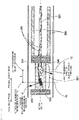
- Fig. 2 is a diagram illustrating the entire configuration of the probe 101 and a cross-sectional configuration of a distal end portion.
- the probe 101 includes a long catheter sheath 201 to be inserted into the inside of the body cavity such as a blood vessel, and a connector unit 202 that is not inserted into the inside of the body cavity such as a blood vessel, and is disposed near the user's hand side so as to be operated by the user.
- a tube for guide wire lumen 203 that configures a guide wire lumen is provided on the distal end of the catheter sheath 201.
- the catheter sheath 201 forms a lumen that continues from the connection section with the tube for guide wire lumen 203 to the connection section with the connector unit 202.
- An imaging core 220 that includes a transmitting and receiving unit 221 and a coil-shaped drive shaft 222 is inserted into the inside portion of the lumen of the catheter sheath 201 throughout almost the entire length of the catheter sheath 201.
- the transmitting and receiving unit 221 is provided with the ultrasound transmitting and receiving unit for transmitting and receiving an ultrasound and the optical transmitting and receiving unit for transmitting and receiving light.
- the drive shaft 222 includes an electric signal cable and an optical fiber cable in the inside portion and transfers a rotary-drive force for rotating the same.
- the connector unit 202 includes a sheath connector 202a that is configured on a proximal end of the catheter sheath 201 in an integrated manner and a drive shaft connector 202b that is configured on a proximal end of the drive shaft 222 in a manner of rotatably fixing the drive shaft 222.
- An anti-kink protector 211 is provided on the boundary portion between the sheath connector 202a and the catheter sheath 201. According to this, the boundary portion maintains a predetermined rigidity, and bending (kinks) caused by the rapid change of physical properties can be prevented.
- the proximal end of the drive shaft connector 202b is detachably attached to the scanner & pull-back unit 102.
- the imaging core 220 including a housing 223 that has the transmitting and receiving unit 221 in which the ultrasound transmitting and receiving unit that transmits and receives the ultrasound and the optical transmitting and receiving unit that transmits and receives light are disposed, and the drive shaft 222 that transfers a rotary-drive force for rotating the transmitting and receiving unit 221 is inserted into the inside portion of the lumen of the catheter sheath 201, throughout the entire length, so as to form the probe 101.
- the transmitting and receiving unit 221 transmits an ultrasound and measurement light to a tissue in the body cavity, and receives a reflected wave and reflected light from the tissue in the body cavity.
- the drive shaft 222 is formed in a coil shape, and an electric signal cable and an optical fiber cable (an optical fiber cable in a single mode) are provided in the inside portion of the drive shaft 222.
- the housing 223 has a shape having notches in a portion of a short cylindrical metal pipe, and is formed by performing carving or metal powder injection molding (MIM) on a metal ingot.
- the housing 223 has the ultrasound transmitting and receiving unit and the optical transmitting and receiving unit in the inside portion as the transmitting and receiving unit 221, and is connected to the drive shaft 222 on the proximal side. Additionally, a short coil-shaped elastic member 231 is provided on the distal side.
- the elastic member 231 is obtained by forming a stainless steel wire into a coil shape and the elastic member 231 is provided on the distal side, when the imaging core 220 is moved back and forth, the imaging core 220 is prevented from being caught in the catheter sheath 201.
- a reinforcement coil 232 is provided for the purpose of preventing the distal end portion of the catheter sheath 201 from being drastically bent.
- the tube for guide wire lumen 203 has a lumen for a guide wire into which the guide wire can be inserted.
- the tube for guide wire lumen 203 is used for receiving the guide wire inserted into the body cavity such as the blood vessel in advance, and for causing the guide wire to guide the catheter sheath 201 to a target lesion.
- the drive shaft 222 is able to cause the transmitting and receiving unit 221 to rotate and move in the axial direction with respect to the catheter sheath 201, and is configured with a multiplex and multilayer contact coil which has a characteristic of being flexible and capable of effectively transferring rotation, and is made with, for example, a metal wire such as stainless steel.
- the transmitting and receiving unit 221 provided in the housing 223 includes an ultrasound transmitting and receiving unit 310 and the optical transmitting and receiving unit 320, and the ultrasound transmitting and receiving unit 310 and the optical transmitting and receiving unit 320 each are disposed along the axial direction on the rotary central axis of the drive shaft 222 (on the alternate long and short dash line in Fig. 3 ).
- Electric signal cables 311 connected to the ultrasound transmitting and receiving unit 310 and an optical fiber cable 321 connected to the optical transmitting and receiving unit 320 are disposed in the inside portion of the drive shaft 222, and the electric signal cables 311 are wound around the optical fiber cable 321 in a spiral shape.
- the ultrasound transmitting and receiving unit 310 is disposed on the distal side of the probe 101 and the optical transmitting and receiving unit 320 is disposed on the proximal side of the probe 101, and the ultrasound transmitting and receiving unit 310 and the optical transmitting and receiving unit 320 are attached in the housing 223 so that a distance between an ultrasound transmission and reception position of the ultrasound transmitting and receiving unit 310 and a light transmission and reception position of the optical transmitting and receiving unit 320 is L.
- the ultrasound transmitting and receiving unit 310 and the optical transmitting and receiving unit 320 are attached in the housing 223 so that the ultrasound transmission direction (elevation angle direction) of the ultrasound transmitting and receiving unit 310 and the light transmission direction (elevation angle direction) of the optical transmitting and receiving unit 320 respectively are formed at about 90° with respect to the axial direction of the drive shaft 222.
- the ultrasound transmitting and receiving unit 310 and the optical transmitting and receiving unit 320 are disposed to be formed at 90° with respect to the axial direction of the drive shaft 222, the intensity of the reflected light from the catheter sheath 201 is strong, and the influence of the reflected noise on the obtained tomographic image is strong. Therefore, it is desirable that the transmitting and receiving units be disposed to have inclinations toward any one of the distal side or the proximal side of the probe 101.
- the transmitting and receiving units are respectively disposed to be inclined in different directions (to the distal side of the probe 101 and to the proximal side of the probe 101), the angles of the observation cross sections cut in the ultrasonic tomographic image and the optical tomographic image become different, and the inconsistency of the observation cross sections is generated.
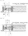
- the transmitting and receiving units are disposed to have inclinations in the same direction along the axial direction of the drive shaft 222. More specifically, as illustrated in Fig. 4A , the ultrasound transmitting and receiving unit 310 is disposed to be inclined by ⁇ ° with respect to a direction orthogonal to the axial direction of the drive shaft 222 toward the distal side of the probe 101, and the optical transmitting and receiving unit 320 is disposed to be inclined by ⁇ ° with respect to a direction orthogonal to the axial direction of the drive shaft 222 toward the distal side of the probe 101.
- ⁇ and ⁇ are the same value.
- angles of ⁇ and ⁇ are great (in the same manner with respect to Figs. 4B , 5A, and 5B to be described below), but ⁇ and ⁇ are set to be 4°, 8°, or the like, in reality.
- the disposition configuration of the transmitting and receiving units is not limited to the configuration illustrated in Fig. 4A , and for example, as illustrated in Fig. 4B , the ultrasound transmitting and receiving unit 310 may be disposed to be inclined by ⁇ ° in the direction orthogonal to the axial direction of the drive shaft 222 toward the proximal side of the probe 101, or the optical transmitting and receiving unit 320 may be disposed to be inclined by ⁇ ° in the direction orthogonal to the axial direction of the drive shaft 222 toward the proximal side of the probe 101.
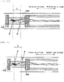
- the ultrasound transmitting and receiving unit 310 and the optical transmitting and receiving unit 320 may be disposed in the configuration illustrated in Fig. 5A or 5B . Even in the cases of Figs. 4B , 5A, and 5B , since the ultrasound transmitting and receiving unit 310 and the optical transmitting and receiving unit 320 are disposed to be inclined in the same direction along the axial direction of the drive shaft 222, the angles of the observation cross sections cut in the ultrasonic tomographic image and the optical tomographic image are caused to be as similar as possible in the same manner as the case of Fig. 4A . According to this, it is possible to cause the observation cross sections of both images to coincide with each other.
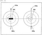
- Fig. 6 is a diagram illustrating the positional relationship between the ultrasound transmitting and receiving unit 310 and the optical transmitting and receiving unit 320 with respect to the surface substantially orthogonal to the rotary axis of the drive shaft 222.
- diagrams on the left side illustrate cross-sectional configurations when an ultrasound transmission and reception position 11 is cut with respect to the surface substantially orthogonal to the rotary central axis
- diagrams on the right side illustrate cross-sectional configurations when a light transmission and reception position 12 is cut with respect to the surface substantially orthogonal to the rotary central axis.
- the ultrasound transmitting and receiving unit 310 and the optical transmitting and receiving unit 320 are disposed on the rotary central axis.
- a light transmission direction (rotary angle direction) 320a indicates a progress direction of light transmitted from the optical transmitting and receiving unit 320 when the light transmission and reception position 12 is cut with respect to the surface substantially orthogonal to the rotary central axis
- an ultrasound transmission direction (rotary angle direction) 310a indicates a progress direction of the ultrasound transmitted from the ultrasound transmitting and receiving unit 310 when an ultrasound transmission and reception position 11 is cut with respect to the surface substantially orthogonal to the rotary central axis.
- the ultrasound transmission direction (rotary angle direction) of the ultrasound transmitting and receiving unit 310 becomes ⁇ . That is, the ultrasound transmitting and receiving unit 310 and the optical transmitting and receiving unit 320 are disposed to be deviated by ⁇ (in this case, 180°) from each other along the rotary angle direction.
- the ultrasound transmission direction 310a of the ultrasound transmitting and receiving unit 310 and the light transmission direction 320a of the optical transmitting and receiving unit 320 may have the positional relationship with respect to the rotary angle direction, and the ultrasound transmitting and receiving unit 310 and the optical transmitting and receiving unit 320 may be disposed, for example, in the positional relationship as illustrated in Fig. 7A .
- the optical transmitting and receiving unit 320 and the ultrasound transmitting and receiving unit 310 are disposed on the same axis (on the rotary central axis) . This is to cause the image center of the constructed ultrasonic tomographic image and the image center of the optical tomographic image to coincide with each other. Note that, it is not necessary that the transmitting and receiving units be disposed on the same axis, and for example, as illustrated in Fig. 7B , the transmitting and receiving unit may be disposed at a position separated from the rotary central axis by a distance r.
- the respective image centers may be adjusted by the image processing when the ultrasound image is generated and when the optical tomographic image is generated, the image center of the ultrasonic tomographic image and the image center of the optical tomographic image coincide with each other in the same manner when the transmitting and receiving units are disposed on the same axis.
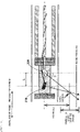
- the imaging apparatus for diagnosis 100 is realized in the configuration of combining the function of IVUS and the function of OCT (here, wavelength sweeping-type OCT as an example). Note that, since the imaging apparatus for diagnosis combining the function of IVUS and another function of OCT also has the same functional configuration, the description thereof is omitted here.
- the imaging core 220 includes the ultrasound transmitting and receiving unit 310 in the inside of the distal end, and the ultrasound transmitting and receiving unit 310 transmits an ultrasound to a biological tissue based on a pulse wave transmitted from an ultrasound signal transmitter and receiver 552, receives a reflected wave (echo) thereof, and transmits the reflected wave to the ultrasound signal transmitter and receiver 552 as an ultrasound echo through an adaptor 502 and a slip ring 551.
- a rotary-drive unit side of the slip ring 551 is rotationally driven by a radial scanning motor 505 of a rotary-drive apparatus 504. Additionally, a rotary angle of the radial scanning motor 505 is detected by an encoder unit 506. Further, the scanner & pull-back unit 102 includes a linear drive apparatus 507, and defines a movement of the imaging core 220 in an axial direction based on a signal from a signal processing unit 528.
- the ultrasound signal transmitter and receiver 552 includes a transmission wave circuit and a reception wave circuit (not illustrated).
- the transmission wave circuit transmits a pulse wave to the ultrasound transmitting and receiving unit 310 in the imaging core 220 based on a control signal transmitted from the signal processing unit 528.
- the reception wave circuit receives an ultrasound signal from the ultrasound transmitting and receiving unit 310 in the imaging core 220. After the received ultrasound signal is amplified by an amplifier 553, the received ultrasound signal is input to a wave detector 554 to be detected.
- an ultrasound signal output from the wave detector 554 is sampled at as many as 200 points at 30.6 MHz to generate digital data (ultrasound data) of 1 line.
- the frequency is set to be 30.6 MHz, but the frequency is calculated on an assumption that 200 points are to be sampled with respect to the depth of 5 mm when the sound velocity is considered to be 1,530 m/sec. Therefore, the sampling frequency is not particularly limited thereto.
- the ultrasound data in a line unit generated in the A/D converter 555 is input to the signal processing unit 528.
- the ultrasound data is converted into a gray scale so as to form the ultrasound tomographic image in each position inside a body cavity such as a blood vessel, and is output to the LCD monitor 113 at a predetermined frame rate.
- the signal processing unit 528 is connected to a motor control circuit 529, and receives a video synchronization signal of the motor control circuit 529.
- the ultrasound tomographic image is constructed by being synchronized with the received video synchronization signal.
- the video synchronization signal of the motor control circuit 529 is also transmitted to the rotary-drive apparatus 504, and the rotary-drive apparatus 504 outputs a drive signal which is synchronized with the video synchronization signal.
- a wavelength swept light source (swept laser) 508 is a type of an extended-cavity laser which is configured to have an optical fiber 516 which is coupled with a semiconductor optical amplifier 515 (SOA) in a ring shape, and a polygon scanning filter (508b).
- SOA semiconductor optical amplifier
- Light output from the SOA 515 proceeds through the optical fiber 516 and is input to the polygon scanning filter 508b, and the light is subjected to wavelength selection herein, is amplified in the SOA 515, and lastly, is output from a coupler 514.
- the wavelength is selected by combining a diffraction grating 512 which performs light-splitting, and a polygon mirror 509.
- rays which is light-split by the diffraction grating 512 are concentrated on a surface of the polygon mirror 509 by using two lenses (510, 511). Accordingly, only the light in a wavelength which is orthogonal to the polygon mirror 509 returns to the same optical path, and is output from the polygon scanning filter 508b. That is, time sweeping of a wavelength can be performed by rotating the polygon mirror 509.
- the polygon mirror 509 for example, a 32-hedron mirror is used and the number of rotations is approximately 50,000 rpm.
- High speed and high output wavelength sweeping can be performed through the wavelength sweeping method in which the polygon mirror 509 and the diffraction grating 512 are combined.
- the first single mode fiber 540 is optically coupled to a second single mode fiber 545, a third single mode fiber 544, and a sixth single mode fiber 546 in a photo coupler unit 541 which are in the intermediate portion.
- an optical rotary joint (optical coupling portion) 503 which connects a non-rotary portion (fixing portion) and a rotary portion (rotary-drive portion) with each other and transfers light is provided inside the rotary-drive apparatus 504.
- a fifth single mode fiber 543 of the probe 101 is freely and detachably connected via the adaptor 502. Accordingly, light from the wavelength swept light source 508 is transferred to the fifth single mode fiber 543 which is inserted through the imaging core 220 to be rotatably driven.
- Transferred light is radiated while performing the radial scanning from the light transmitting and receiving unit 320 of the imaging core 220 to a biological tissue inside a body cavity. Then, a portion of reflected light scattered in the inside or on a surface of a biological tissue is collected by the light transmitting and receiving unit 320 of the imaging core 220, and returns to the first single mode fiber 540 side via an optical path in reverse. Further, the portion of the reflected light moves to the second single mode fiber 545 side by the photo coupler unit 541, and the light is received by the light detector (for example, photo-diode 524) after being emitted from an end of the second single mode fiber 545.
- the light detector for example, photo-diode 524
- the rotary-drive portion side of the optical rotary joint 503 is rotationally driven by the radial scanning motor 505 of the rotary-drive apparatus 504. Additionally, a rotary angle of the radial scanning motor 505 is detected by the encoder unit 506. Further, the scanner & pull-back unit 102 includes the linear drive apparatus 507 and defines the axial-direction operation of the imaging core 220 based on an instruction from the signal processing unit 528.
- an optical path length varying mechanism 532 for fine-adjusting the optical path length of the reference light is provided in a distal end on a side opposite to the photo coupler unit 541 of the third single mode fiber 544.
- the optical path length varying mechanism 532 includes optical path length changing means for changing the optical path length corresponding to a fluctuation in a length of each probe 101 so as to be able to absorb the fluctuation in the length thereof when the probe 101 is replaced and used.
- the third single mode fiber 544 and a collimating lens 518 are provided on a one-axis stage 522 which is movable in an optical-axis direction as indicated by the arrow 523, and forms the optical path length changing means.
- the one-axis stage 522 functions as the optical path length changing means having a movable range of the optical path length as wide as the fluctuation in the optical path length of the probe 101 can be absorbed when the probe 101 is replaced. Further, the one-axis stage 522 also includes a function as adjustment means for adjusting an offset. For example, when the distal end of the probe 101 is not in close contact with a surface of a biological tissue, it is possible to set a state of being interfered with the reflected light from the surface position of the biological tissue by minutely changing the optical path length through the one-axis stage.
- the optical path length is fine-adjusted in the one-axis stage 522, and light reflected by the mirror 521 via a grating 519 and a lens 520 is mixed with light acquired from the sixth single mode fiber 546 side in the photo coupler unit 541 which is provided in an intermediate portion of the third single mode fiber 544, and thus, the light is received in the photo-diode 524.
- the interference light received in the photo-diode 524 in this manner is subjected to photoelectric conversion, thereby being input to a demodulator 526 after being amplified by the amplifier 525.
- demodulator 526 demodulation processing in which only the signal portion is extracted from the interfered light is performed, and the output is input to an A/D converter 527 as an interference light signal.
- an interference light signal is sampled, for example, at as many as 2,048 points at 180 MHz, thereby generating digital data (interference light data) of 1 line.
- the sampling frequency is set to 180 MHz on a premise that approximately 90% of a periodical cycle (12.5 ⁇ sec) of the wavelength sweep is extracted as digital data of 2,048 points when a repetition frequency of the wavelength sweep is set to 40 kHz, without being particularly limited thereto.
- the interference light data in a line unit generated in the A/D converter 527 is input to the signal processing unit 528.
- the interference light data is subjected to frequency resolution through Fast Fourier Transform (FFT) in the signal processing unit 528 so as to generate data in a depth direction (line data), and the line data is subjected to coordinate-conversion to construct a light tomographic image in each position inside a body cavity such as a blood vessel, thereby being output to the LCD monitor 113 at a predetermined frame rate.
- FFT Fast Fourier Transform
- the signal processing unit 528 is further connected to an optical path length adjustment means control device 530.
- the signal processing unit 528 controls a position of the one-axis stage 522 via the optical path length adjustment means control device 530.
- the ultrasonic tomographic image and the optical tomographic image are displayed on the imaging apparatus for diagnosis 100 (the LCD monitor 113) toward the user.
- the imaging apparatus for diagnosis 100 the LCD monitor 113
- respective tomographic images corresponding to respective positions in the axial direction of the body cavity such as a blood vessel may be displayed in parallel, or may be displayed to be overlapped so that the image centers coincide, without being particularly limited thereto.
- the ultrasound transmitting and receiving unit 310 and the optical transmitting and receiving unit 320 are disposed to be inclined in the same direction along the axial direction of the drive shaft 222. According to this, the angles of the observation cross sections (cut cross section) according to the ultrasonic tomographic image and the optical tomographic image can be formed as similar as possible.
- the inclination angle of the optical transmitting and receiving unit 320 may be greater than the inclination angle of the ultrasound transmitting and receiving unit 310 ( ⁇ ) .
- the light transmitted from the optical transmitting and receiving unit 320 provided on the proximal side of the probe 101 intersects with the ultrasound transmitted from the ultrasound transmitting and receiving unit 310 provided on the distal side of the probe 101 near the intermediate portion of the observation scopes (positions separated from the rotary axis by a distance Z), it is possible to obtain the tomographic images at substantially the same positions.
- ⁇ , ⁇ there are optimum inclinations ( ⁇ , ⁇ ) for respective signals (light and ultrasound). Therefore, a distance between sensors of respective signals (distance between the ultrasound transmitting and receiving unit 310 and the optical transmitting and receiving unit 320) is unambiguously determined by the optimum angles. Since a configuration in which the sensors intersect in the same direction along the axial direction is employed, the distance between the sensors becomes shorter than in the configuration in which the sensors intersect in the different directions along the axial direction.
- the ultrasound transmitting and receiving unit 310 is disposed on the distal side and the optical transmitting and receiving unit 320 is disposed on the proximal side is described, but the invention is not limited thereto. That is, the optical transmitting and receiving unit 320 may be disposed on the distal side, and the ultrasound transmitting and receiving unit 310 may be disposed on the proximal side.
- the configuration described in Modification example 1 may be applied to the configuration described in Modification example 2.
- the inclination angle of the ultrasound transmitting and receiving unit 310 provided on the proximal side of the probe 101 may be greater than the inclination angle (with respect to the orthogonal direction to the axial direction) of the optical transmitting and receiving unit 320 provided on the distal side of the probe 101.
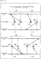
- the angles of the first transmitting and receiving unit 21 and the second transmitting and receiving unit 22 may satisfy ⁇ , as indicated by Reference number 31.
- the angles of the first transmitting and receiving unit 21 and the second transmitting and receiving unit 22 may be ⁇ in the same manner as in the description of Reference number 31.
- the angles of the first transmitting and receiving unit 21 and the second transmitting and receiving unit 22 may be ⁇ > ⁇ as indicated by Reference number 33. Further, as indicated by Reference number 34, even if the rotary angle directions of the first transmitting and receiving unit 21 and the second transmitting and receiving unit 22 are different from each other by approximately 180°, the angles of the first transmitting and receiving unit 21 and the second transmitting and receiving unit 22 may be ⁇ > ⁇ in the same manner as in the description of Reference number 33.
- the plurality of transmitting and receiving units are provided in the probe
- the ultrasound transmitting and receiving unit and the optical transmitting and receiving unit are provided in the probe
- the present invention is not limited thereto.
- the plurality of optical transmitting and receiving units may be provided.
- a plurality of optical fiber cables corresponding to respective optical transmitting and receiving units are also provided.
- an optical transmitting and receiving unit 41 and an optical transmitting and receiving unit 42 may be disposed to be inclined in the same directions along the axial direction, and the angles ( ⁇ , ⁇ ) with respect to the direction orthogonal to the axial direction may be the same or may be different from each other (in this case, the inclination of the optical transmitting and receiving unit 42 (that is, ⁇ ) is set to be great) as illustrated in Fig. 11(b) .
- the angles of the transmitting and receiving units may be adjusted in this regard.
- the plurality of optical transmitting and receiving units are provided, but it is obvious that the plurality of ultrasound transmitting and receiving units may be provided. In this case, in the same manner as described above, the tomographic images can be obtained at a high speed.
Claims (8)
- Sonde (101), die so konfiguriert ist, dass sie abnehmbar an einer drehbaren Verbindungseinheit (102) einer Bildgebungsvorrichtung (100) für die Diagnose angebracht ist und in eine Innenseite eines Körperlumens eingeführt werden kann, umfassend:eine Mehrzahl von Sende- und Empfangseinheiten, die so konfiguriert sind, dass sie tomographische Bilder durch Senden und Empfangen von Signalen von der Innenseite des Körperlumens erhalten; undeine Antriebswelle (222), die so konfiguriert ist, dass sie eine Drehantriebskraft von der drehbaren Verbindungseinheit (102) empfängt und die Mehrzahl von Sende- und Empfangseinheiten dreht,wobei die Mehrzahl von Sende- und Empfangseinheiten jeweils entlang der axialen Richtung der Antriebswelle (222) angeordnet sind, die in der gleichen Richtung durch Winkel (a, β) in Bezug auf eine Richtung orthogonal zu der axialen Richtung der Antriebswelle (222) geneigt sind, sodass die Signale in Richtungen entweder zu einer distalen Seite der Sonde (101) oder zu einer proximalen Seite der Sonde (101) gesendet werden,wobei jede von der Mehrzahl der Sende- und Empfangseinheiten aus einer Ultraschall-Sende- und Empfangseinheit (310), die einen Ultraschall sendet und empfängt, und einer optischen Sende- und Empfangseinheit (320), die Licht sendet und empfängt, ausgewählt ist,wobei eine von der Mehrzahl der Sende- und Empfangseinheiten (310, 320) an der distalen Seite der Sonde (101) angeordnet ist und die andere von der Mehrzahl der Sende- und Empfangseinheiten (310, 320) an der proximalen Seite der Sonde (101) angeordnet ist, sodass ein Abstand zwischen ihnen (310, 320) L beträgt.
- Sonde (101) nach Anspruch 1,wobei, wenn die Mehrzahl der Sende- und Empfangseinheiten durch die Winkel so angeordnet ist, dass die Signale zu der distalen Seite der Sonde (101) gesendet werden, der Winkel der Sende- und Empfangseinheit, die auf der proximalen Seite der Sonde (101) angeordnet ist, gleich oder größer ist als der Winkel von der anderen Sende- und Empfangseinheit, die auf der distalen Seite der Sonde (101) vorgesehen ist, undwobei, wenn die Mehrzahl der Sende- und Empfangseinheiten durch die Winkel so angeordnet ist, dass die Signale zu der proximalen Seite der Sonde (101) gesendet werden, der Winkel der Sende- und Empfangseinheit, die auf der distalen Seite der Sonde (101) angeordnet ist, gleich oder größer ist als der Winkel von der anderen Sende- und Empfangseinheit, die auf der proximalen Seite der Sonde (101) vorgesehen ist.
- Sonde (101) nach Anspruch 1 oder 2,
wobei die Winkel von der Mehrzahl der Sende- und Empfangseinheiten identisch sind. - Sonde (101) nach Anspruch 2,wobei, wenn die Mehrzahl der Sende- und Empfangseinheiten durch die Winkel zu der distalen Seite der Sonde (101) angeordnet ist, der Winkel von der Sende- und Empfangseinheit, die auf der proximalen Seite der Sonde (101) angeordnet ist, größer ist als der Winkel von der anderen Sende- und Empfangseinheit, die auf der distalen Seite der Sonde (101) angeordnet ist, undwobei, wenn die Mehrzahl der Sende- und Empfangseinheiten durch die Winkel zu der proximalen Seite der Sonde (101) angeordnet ist, der Winkel von der Sende- und Empfangseinheit, die auf der distalen Seite der Sonde (101) angeordnet ist, größer ist als der Winkel von der anderen Sende- und Empfangseinheit, die auf der proximalen Seite der Sonde (101) angeordnet ist.
- Sonde (101) nach Anspruch 4,wobei, wenn die Mehrzahl der Sende- und Empfangseinheiten durch die Winkel zu der distalen Seite der Sonde (101) angeordnet sind, die Sende- und Empfangseinheit, die auf der proximalen Seite der Sonde (101) angeordnet ist, durch den entsprechenden Winkel angeordnet ist, sodass eine Position abgetastet wird, die identisch mit der Position in dem Körperlumen ist, die durch das Signal abgetastet wird, das von der anderen Sende- und Empfangseinheit, die auf der distalen Seite der Sonde (101) angeordnet ist, gesendet wird, undwobei, wenn die Mehrzahl der Sende- und Empfangseinheiten durch die Winkel zu der proximalen Seite der Sonde (101) angeordnet sind, die Sende- und Empfangseinheit, die auf der distalen Seite der Sonde (101) angeordnet ist, durch den entsprechenden Winkel angeordnet ist, sodass eine Position abgetastet wird, die identisch mit der Position in dem Körperlumen ist, die durch das Signal abgetastet wird, das von der anderen Sende- und Empfangseinheit, die auf der proximalen Seite der Sonde (101) angeordnet ist, gesendet wird.
- Sonde (101) nach einem der Ansprüche 1 bis 4,
wobei die Mehrzahl der Sende- und Empfangseinheiten eine Mehrzahl von optischen Sende- und Empfangseinheiten (320) umfasst, die Licht senden und empfangen. - Sonde (101) nach einem der Ansprüche 1 bis 4,
wobei die Mehrzahl der Sende- und Empfangseinheiten eine Mehrzahl von Ultraschall-Sende- und Empfangseinheiten (310) umfasst, die Ultraschall senden und empfangen. - Bildgebungsvorrichtung (100) für die Diagnose, umfassend:die Sonde (101) nach einem der Ansprüche 1 bis 7, und die drehbare Verbindungseinheit (102), an welcher die Sonde (101) angebracht ist,wobei die Bildgebungsvorrichtung (100) für die Diagnose so konfiguriert ist, dass sie die in der Sonde (101) gesendeten und empfangenen Signale verwendet und ein tomographisches Bild in der Innenseite des Körperlumens erzeugt.
Applications Claiming Priority (2)
| Application Number | Priority Date | Filing Date | Title |
|---|---|---|---|
| JP2012072857 | 2012-03-28 | ||
| PCT/JP2013/002005 WO2013145689A1 (ja) | 2012-03-28 | 2013-03-25 | プローブ及び画像診断装置 |
Publications (3)
| Publication Number | Publication Date |
|---|---|
| EP2832301A1 EP2832301A1 (de) | 2015-02-04 |
| EP2832301A4 EP2832301A4 (de) | 2015-12-02 |
| EP2832301B1 true EP2832301B1 (de) | 2022-10-05 |
Family
ID=49258992
Family Applications (1)
| Application Number | Title | Priority Date | Filing Date |
|---|---|---|---|
| EP13768700.0A Active EP2832301B1 (de) | 2012-03-28 | 2013-03-25 | Sonde und diagnostische bildgebungsvorrichtung |
Country Status (4)
| Country | Link |
|---|---|
| US (1) | US20150005626A1 (de) |
| EP (1) | EP2832301B1 (de) |
| JP (1) | JP6117772B2 (de) |
| WO (1) | WO2013145689A1 (de) |
Families Citing this family (13)
| Publication number | Priority date | Publication date | Assignee | Title |
|---|---|---|---|---|
| JP6563941B2 (ja) * | 2014-09-26 | 2019-08-21 | テルモ株式会社 | 画像診断プローブ |
| JP6533078B2 (ja) | 2015-03-20 | 2019-06-19 | テルモ株式会社 | 画像診断装置、その制御方法、プログラム及びコンピュータ可読記憶媒体 |
| JP6559985B2 (ja) * | 2015-03-20 | 2019-08-14 | テルモ株式会社 | 画像診断プローブ |
| AU2016304925B2 (en) * | 2015-08-12 | 2019-11-21 | Securus Medical Group, Inc. | Temperature measurement systems, method and devices |
| JP6981967B2 (ja) | 2015-08-31 | 2021-12-17 | ジェンテュイティ・リミテッド・ライアビリティ・カンパニーGentuity, LLC | 撮像プローブおよびデリバリデバイスを含む撮像システム |
| ES2859105T3 (es) | 2016-05-25 | 2021-10-01 | Shell Int Research | Proceso para el tratamiento de aguas residuales |
| CN110809432B (zh) * | 2017-06-29 | 2023-07-25 | 泰尔茂株式会社 | 图像诊断用导管 |
| CN116022905A (zh) | 2017-11-23 | 2023-04-28 | 国际壳牌研究有限公司 | 用于废水处理的方法 |
| JP7160935B2 (ja) | 2017-11-28 | 2022-10-25 | ジェンテュイティ・リミテッド・ライアビリティ・カンパニー | 撮像システム |
| CN109044243A (zh) * | 2018-06-29 | 2018-12-21 | 华南师范大学 | 一种前置微型电机高精度三维扫描的光声内窥镜及成像方法 |
| CN113631099B (zh) * | 2019-03-29 | 2023-09-19 | 泰尔茂株式会社 | 图像诊断用导管 |
| CN110367931A (zh) * | 2019-07-09 | 2019-10-25 | 中国人民解放军军事科学院军事医学研究院 | 一种基于飞秒激光的光断层透射成像系统 |
| JPWO2022209705A1 (de) * | 2021-03-29 | 2022-10-06 |
Family Cites Families (12)
| Publication number | Priority date | Publication date | Assignee | Title |
|---|---|---|---|---|
| JP3869589B2 (ja) * | 1999-09-02 | 2007-01-17 | ペンタックス株式会社 | ファイババンドル及び内視鏡装置 |
| DE10343808B4 (de) * | 2003-09-22 | 2017-06-01 | Siemens Healthcare Gmbh | Medizinisches Untersuchungs- und/oder Behandlungssystem |
| US6949072B2 (en) * | 2003-09-22 | 2005-09-27 | Infraredx, Inc. | Devices for vulnerable plaque detection |
| DE10354496B4 (de) | 2003-11-21 | 2011-03-31 | Siemens Ag | Medizinisches Untersuchungs- und/oder Behandlungssystem |
| JP4429886B2 (ja) | 2004-12-09 | 2010-03-10 | 富士フイルム株式会社 | 光断層映像装置 |
| EP2628443B1 (de) * | 2006-11-08 | 2021-05-12 | Lightlab Imaging, Inc. | Opto-akustische Abbildungsvorrichtung |
| JP2010516304A (ja) * | 2007-01-19 | 2010-05-20 | サニーブルック・ヘルス・サイエンシズ・センター | 超音波と光学を複合した画像手段を有する撮像プローブ |
| WO2009009802A1 (en) * | 2007-07-12 | 2009-01-15 | Volcano Corporation | Oct-ivus catheter for concurrent luminal imaging |
| EP2282676A2 (de) * | 2008-05-07 | 2011-02-16 | InfraReDx, Inc. | Katheter mit rotierender ultraschall-transceiverplatine |
| JP5524947B2 (ja) * | 2009-02-24 | 2014-06-18 | テルモ株式会社 | 画像診断装置及びその作動方法 |
| WO2011039983A1 (ja) * | 2009-09-30 | 2011-04-07 | テルモ株式会社 | 画像診断装置及びその制御方法 |
| US11701089B2 (en) * | 2012-11-19 | 2023-07-18 | Lightlab Imaging, Inc. | Multimodal imaging systems, probes and methods |
-
2013
- 2013-03-25 WO PCT/JP2013/002005 patent/WO2013145689A1/ja active Application Filing
- 2013-03-25 EP EP13768700.0A patent/EP2832301B1/de active Active
- 2013-03-25 JP JP2014507422A patent/JP6117772B2/ja active Active
-
2014
- 2014-09-15 US US14/486,256 patent/US20150005626A1/en not_active Abandoned
Also Published As
| Publication number | Publication date |
|---|---|
| JP6117772B2 (ja) | 2017-04-19 |
| US20150005626A1 (en) | 2015-01-01 |
| EP2832301A4 (de) | 2015-12-02 |
| WO2013145689A1 (ja) | 2013-10-03 |
| EP2832301A1 (de) | 2015-02-04 |
| JPWO2013145689A1 (ja) | 2015-12-10 |
Similar Documents
| Publication | Publication Date | Title |
|---|---|---|
| EP2832301B1 (de) | Sonde und diagnostische bildgebungsvorrichtung | |
| JP6001765B2 (ja) | 画像診断装置及びプログラム | |
| JP5981557B2 (ja) | 画像診断装置 | |
| JP5956589B2 (ja) | 画像診断装置及びその作動方法及びプログラム | |
| EP2832303B1 (de) | Sonde und diagnostische bildgebungsvorrichtung | |
| US11717262B2 (en) | Imaging apparatus for diagnosis and program | |
| EP2832300B1 (de) | Tomografische bilderzeugungsvorrichtung | |
| WO2016152624A1 (ja) | 画像診断装置及びその制御方法、プログラム及びコンピュータ可読記憶媒体 | |
| JP5913607B2 (ja) | 校正冶具、画像診断装置及び画像診断装置の校正方法 | |
| JP6062421B2 (ja) | 画像診断装置及びその作動方法 | |
| WO2014049641A1 (ja) | 画像診断装置及び情報処理装置並びにそれらの制御方法 | |
| JP2016131592A (ja) | 光ケーブル及び光画像診断装置 |
Legal Events
| Date | Code | Title | Description |
|---|---|---|---|
| PUAI | Public reference made under article 153(3) epc to a published international application that has entered the european phase |
Free format text: ORIGINAL CODE: 0009012 |
|
| 17P | Request for examination filed |
Effective date: 20140918 |
|
| AK | Designated contracting states |
Kind code of ref document: A1 Designated state(s): AL AT BE BG CH CY CZ DE DK EE ES FI FR GB GR HR HU IE IS IT LI LT LU LV MC MK MT NL NO PL PT RO RS SE SI SK SM TR |
|
| AX | Request for extension of the european patent |
Extension state: BA ME |
|
| DAX | Request for extension of the european patent (deleted) | ||
| RA4 | Supplementary search report drawn up and despatched (corrected) |
Effective date: 20151029 |
|
| RIC1 | Information provided on ipc code assigned before grant |
Ipc: A61B 8/12 20060101AFI20151023BHEP Ipc: A61B 5/00 20060101ALI20151023BHEP |
|
| STAA | Information on the status of an ep patent application or granted ep patent |
Free format text: STATUS: EXAMINATION IS IN PROGRESS |
|
| 17Q | First examination report despatched |
Effective date: 20190520 |
|
| STAA | Information on the status of an ep patent application or granted ep patent |
Free format text: STATUS: EXAMINATION IS IN PROGRESS |
|
| GRAP | Despatch of communication of intention to grant a patent |
Free format text: ORIGINAL CODE: EPIDOSNIGR1 |
|
| STAA | Information on the status of an ep patent application or granted ep patent |
Free format text: STATUS: GRANT OF PATENT IS INTENDED |
|
| RIC1 | Information provided on ipc code assigned before grant |
Ipc: A61B 5/00 20060101ALI20220329BHEP Ipc: A61B 8/08 20060101ALI20220329BHEP Ipc: A61B 8/12 20060101AFI20220329BHEP |
|
| INTG | Intention to grant announced |
Effective date: 20220422 |
|
| GRAS | Grant fee paid |
Free format text: ORIGINAL CODE: EPIDOSNIGR3 |
|
| GRAA | (expected) grant |
Free format text: ORIGINAL CODE: 0009210 |
|
| STAA | Information on the status of an ep patent application or granted ep patent |
Free format text: STATUS: THE PATENT HAS BEEN GRANTED |
|
| AK | Designated contracting states |
Kind code of ref document: B1 Designated state(s): AL AT BE BG CH CY CZ DE DK EE ES FI FR GB GR HR HU IE IS IT LI LT LU LV MC MK MT NL NO PL PT RO RS SE SI SK SM TR |
|
| REG | Reference to a national code |
Ref country code: GB Ref legal event code: FG4D |
|
| REG | Reference to a national code |
Ref country code: CH Ref legal event code: EP |
|
| REG | Reference to a national code |
Ref country code: AT Ref legal event code: REF Ref document number: 1522244 Country of ref document: AT Kind code of ref document: T Effective date: 20221015 |
|
| REG | Reference to a national code |
Ref country code: IE Ref legal event code: FG4D |
|
| REG | Reference to a national code |
Ref country code: DE Ref legal event code: R096 Ref document number: 602013082633 Country of ref document: DE |
|
| REG | Reference to a national code |
Ref country code: LT Ref legal event code: MG9D |
|
| REG | Reference to a national code |
Ref country code: NL Ref legal event code: MP Effective date: 20221005 |
|
| REG | Reference to a national code |
Ref country code: AT Ref legal event code: MK05 Ref document number: 1522244 Country of ref document: AT Kind code of ref document: T Effective date: 20221005 |
|
| PG25 | Lapsed in a contracting state [announced via postgrant information from national office to epo] |
Ref country code: NL Free format text: LAPSE BECAUSE OF FAILURE TO SUBMIT A TRANSLATION OF THE DESCRIPTION OR TO PAY THE FEE WITHIN THE PRESCRIBED TIME-LIMIT Effective date: 20221005 |
|
| PG25 | Lapsed in a contracting state [announced via postgrant information from national office to epo] |
Ref country code: SE Free format text: LAPSE BECAUSE OF FAILURE TO SUBMIT A TRANSLATION OF THE DESCRIPTION OR TO PAY THE FEE WITHIN THE PRESCRIBED TIME-LIMIT Effective date: 20221005 Ref country code: PT Free format text: LAPSE BECAUSE OF FAILURE TO SUBMIT A TRANSLATION OF THE DESCRIPTION OR TO PAY THE FEE WITHIN THE PRESCRIBED TIME-LIMIT Effective date: 20230206 Ref country code: NO Free format text: LAPSE BECAUSE OF FAILURE TO SUBMIT A TRANSLATION OF THE DESCRIPTION OR TO PAY THE FEE WITHIN THE PRESCRIBED TIME-LIMIT Effective date: 20230105 Ref country code: LT Free format text: LAPSE BECAUSE OF FAILURE TO SUBMIT A TRANSLATION OF THE DESCRIPTION OR TO PAY THE FEE WITHIN THE PRESCRIBED TIME-LIMIT Effective date: 20221005 Ref country code: FI Free format text: LAPSE BECAUSE OF FAILURE TO SUBMIT A TRANSLATION OF THE DESCRIPTION OR TO PAY THE FEE WITHIN THE PRESCRIBED TIME-LIMIT Effective date: 20221005 Ref country code: ES Free format text: LAPSE BECAUSE OF FAILURE TO SUBMIT A TRANSLATION OF THE DESCRIPTION OR TO PAY THE FEE WITHIN THE PRESCRIBED TIME-LIMIT Effective date: 20221005 Ref country code: AT Free format text: LAPSE BECAUSE OF FAILURE TO SUBMIT A TRANSLATION OF THE DESCRIPTION OR TO PAY THE FEE WITHIN THE PRESCRIBED TIME-LIMIT Effective date: 20221005 |
|
| PGFP | Annual fee paid to national office [announced via postgrant information from national office to epo] |
Ref country code: FR Payment date: 20230208 Year of fee payment: 11 |
|
| PG25 | Lapsed in a contracting state [announced via postgrant information from national office to epo] |
Ref country code: RS Free format text: LAPSE BECAUSE OF FAILURE TO SUBMIT A TRANSLATION OF THE DESCRIPTION OR TO PAY THE FEE WITHIN THE PRESCRIBED TIME-LIMIT Effective date: 20221005 Ref country code: PL Free format text: LAPSE BECAUSE OF FAILURE TO SUBMIT A TRANSLATION OF THE DESCRIPTION OR TO PAY THE FEE WITHIN THE PRESCRIBED TIME-LIMIT Effective date: 20221005 Ref country code: LV Free format text: LAPSE BECAUSE OF FAILURE TO SUBMIT A TRANSLATION OF THE DESCRIPTION OR TO PAY THE FEE WITHIN THE PRESCRIBED TIME-LIMIT Effective date: 20221005 Ref country code: IS Free format text: LAPSE BECAUSE OF FAILURE TO SUBMIT A TRANSLATION OF THE DESCRIPTION OR TO PAY THE FEE WITHIN THE PRESCRIBED TIME-LIMIT Effective date: 20230205 Ref country code: HR Free format text: LAPSE BECAUSE OF FAILURE TO SUBMIT A TRANSLATION OF THE DESCRIPTION OR TO PAY THE FEE WITHIN THE PRESCRIBED TIME-LIMIT Effective date: 20221005 Ref country code: GR Free format text: LAPSE BECAUSE OF FAILURE TO SUBMIT A TRANSLATION OF THE DESCRIPTION OR TO PAY THE FEE WITHIN THE PRESCRIBED TIME-LIMIT Effective date: 20230106 |
|
| REG | Reference to a national code |
Ref country code: DE Ref legal event code: R097 Ref document number: 602013082633 Country of ref document: DE |
|
| PG25 | Lapsed in a contracting state [announced via postgrant information from national office to epo] |
Ref country code: SM Free format text: LAPSE BECAUSE OF FAILURE TO SUBMIT A TRANSLATION OF THE DESCRIPTION OR TO PAY THE FEE WITHIN THE PRESCRIBED TIME-LIMIT Effective date: 20221005 Ref country code: RO Free format text: LAPSE BECAUSE OF FAILURE TO SUBMIT A TRANSLATION OF THE DESCRIPTION OR TO PAY THE FEE WITHIN THE PRESCRIBED TIME-LIMIT Effective date: 20221005 Ref country code: EE Free format text: LAPSE BECAUSE OF FAILURE TO SUBMIT A TRANSLATION OF THE DESCRIPTION OR TO PAY THE FEE WITHIN THE PRESCRIBED TIME-LIMIT Effective date: 20221005 Ref country code: DK Free format text: LAPSE BECAUSE OF FAILURE TO SUBMIT A TRANSLATION OF THE DESCRIPTION OR TO PAY THE FEE WITHIN THE PRESCRIBED TIME-LIMIT Effective date: 20221005 Ref country code: CZ Free format text: LAPSE BECAUSE OF FAILURE TO SUBMIT A TRANSLATION OF THE DESCRIPTION OR TO PAY THE FEE WITHIN THE PRESCRIBED TIME-LIMIT Effective date: 20221005 |
|
| PLBE | No opposition filed within time limit |
Free format text: ORIGINAL CODE: 0009261 |
|
| STAA | Information on the status of an ep patent application or granted ep patent |
Free format text: STATUS: NO OPPOSITION FILED WITHIN TIME LIMIT |
|
| PG25 | Lapsed in a contracting state [announced via postgrant information from national office to epo] |
Ref country code: SK Free format text: LAPSE BECAUSE OF FAILURE TO SUBMIT A TRANSLATION OF THE DESCRIPTION OR TO PAY THE FEE WITHIN THE PRESCRIBED TIME-LIMIT Effective date: 20221005 Ref country code: AL Free format text: LAPSE BECAUSE OF FAILURE TO SUBMIT A TRANSLATION OF THE DESCRIPTION OR TO PAY THE FEE WITHIN THE PRESCRIBED TIME-LIMIT Effective date: 20221005 |
|
| 26N | No opposition filed |
Effective date: 20230706 |
|
| PG25 | Lapsed in a contracting state [announced via postgrant information from national office to epo] |
Ref country code: MC Free format text: LAPSE BECAUSE OF FAILURE TO SUBMIT A TRANSLATION OF THE DESCRIPTION OR TO PAY THE FEE WITHIN THE PRESCRIBED TIME-LIMIT Effective date: 20221005 |
|
| REG | Reference to a national code |
Ref country code: CH Ref legal event code: PL |
|
| PG25 | Lapsed in a contracting state [announced via postgrant information from national office to epo] |
Ref country code: SI Free format text: LAPSE BECAUSE OF FAILURE TO SUBMIT A TRANSLATION OF THE DESCRIPTION OR TO PAY THE FEE WITHIN THE PRESCRIBED TIME-LIMIT Effective date: 20221005 |
|
| REG | Reference to a national code |
Ref country code: BE Ref legal event code: MM Effective date: 20230331 |
|
| PG25 | Lapsed in a contracting state [announced via postgrant information from national office to epo] |
Ref country code: LU Free format text: LAPSE BECAUSE OF NON-PAYMENT OF DUE FEES Effective date: 20230325 |
|
| REG | Reference to a national code |
Ref country code: IE Ref legal event code: MM4A |
|
| PG25 | Lapsed in a contracting state [announced via postgrant information from national office to epo] |
Ref country code: LI Free format text: LAPSE BECAUSE OF NON-PAYMENT OF DUE FEES Effective date: 20230331 Ref country code: IE Free format text: LAPSE BECAUSE OF NON-PAYMENT OF DUE FEES Effective date: 20230325 Ref country code: CH Free format text: LAPSE BECAUSE OF NON-PAYMENT OF DUE FEES Effective date: 20230331 |
|
| PG25 | Lapsed in a contracting state [announced via postgrant information from national office to epo] |
Ref country code: BE Free format text: LAPSE BECAUSE OF NON-PAYMENT OF DUE FEES Effective date: 20230331 |
|
| PGFP | Annual fee paid to national office [announced via postgrant information from national office to epo] |
Ref country code: DE Payment date: 20240130 Year of fee payment: 12 Ref country code: GB Payment date: 20240201 Year of fee payment: 12 |