EP2829333B1 - Tape reel arrangement for winding and/or unwinding a metal strip - Google Patents
Tape reel arrangement for winding and/or unwinding a metal strip Download PDFInfo
- Publication number
- EP2829333B1 EP2829333B1 EP14172015.1A EP14172015A EP2829333B1 EP 2829333 B1 EP2829333 B1 EP 2829333B1 EP 14172015 A EP14172015 A EP 14172015A EP 2829333 B1 EP2829333 B1 EP 2829333B1
- Authority
- EP
- European Patent Office
- Prior art keywords
- tape reel
- reel assembly
- metal strip
- longitudinal
- side wall
- Prior art date
- Legal status (The legal status is an assumption and is not a legal conclusion. Google has not performed a legal analysis and makes no representation as to the accuracy of the status listed.)
- Active
Links
- 239000002184 metal Substances 0.000 title claims description 43
- 238000004804 winding Methods 0.000 title description 4
- 239000000463 material Substances 0.000 claims description 8
- 230000000712 assembly Effects 0.000 claims description 4
- 238000000429 assembly Methods 0.000 claims description 4
- 238000011144 upstream manufacturing Methods 0.000 claims description 3
- 238000010276 construction Methods 0.000 description 3
- 238000004146 energy storage Methods 0.000 description 3
- 238000005452 bending Methods 0.000 description 1
- 230000006835 compression Effects 0.000 description 1
- 238000007906 compression Methods 0.000 description 1
- 238000006073 displacement reaction Methods 0.000 description 1
- 238000003780 insertion Methods 0.000 description 1
- 230000037431 insertion Effects 0.000 description 1
- 238000000034 method Methods 0.000 description 1
Images

Classifications
-
- B—PERFORMING OPERATIONS; TRANSPORTING
- B21—MECHANICAL METAL-WORKING WITHOUT ESSENTIALLY REMOVING MATERIAL; PUNCHING METAL
- B21C—MANUFACTURE OF METAL SHEETS, WIRE, RODS, TUBES OR PROFILES, OTHERWISE THAN BY ROLLING; AUXILIARY OPERATIONS USED IN CONNECTION WITH METAL-WORKING WITHOUT ESSENTIALLY REMOVING MATERIAL
- B21C47/00—Winding-up, coiling or winding-off metal wire, metal band or other flexible metal material characterised by features relevant to metal processing only
- B21C47/32—Tongs or gripping means specially adapted for reeling operations
- B21C47/326—Devices for pressing the end of the material being wound against the cylindrical wall of the reel or bobbin
-
- B—PERFORMING OPERATIONS; TRANSPORTING
- B21—MECHANICAL METAL-WORKING WITHOUT ESSENTIALLY REMOVING MATERIAL; PUNCHING METAL
- B21C—MANUFACTURE OF METAL SHEETS, WIRE, RODS, TUBES OR PROFILES, OTHERWISE THAN BY ROLLING; AUXILIARY OPERATIONS USED IN CONNECTION WITH METAL-WORKING WITHOUT ESSENTIALLY REMOVING MATERIAL
- B21C47/00—Winding-up, coiling or winding-off metal wire, metal band or other flexible metal material characterised by features relevant to metal processing only
- B21C47/02—Winding-up or coiling
- B21C47/04—Winding-up or coiling on or in reels or drums, without using a moving guide
- B21C47/06—Winding-up or coiling on or in reels or drums, without using a moving guide with loaded rollers, bolts, or equivalent means holding the material on the reel or drum
- B21C47/063—Winding-up or coiling on or in reels or drums, without using a moving guide with loaded rollers, bolts, or equivalent means holding the material on the reel or drum with pressure rollers only
-
- B—PERFORMING OPERATIONS; TRANSPORTING
- B21—MECHANICAL METAL-WORKING WITHOUT ESSENTIALLY REMOVING MATERIAL; PUNCHING METAL
- B21C—MANUFACTURE OF METAL SHEETS, WIRE, RODS, TUBES OR PROFILES, OTHERWISE THAN BY ROLLING; AUXILIARY OPERATIONS USED IN CONNECTION WITH METAL-WORKING WITHOUT ESSENTIALLY REMOVING MATERIAL
- B21C47/00—Winding-up, coiling or winding-off metal wire, metal band or other flexible metal material characterised by features relevant to metal processing only
- B21C47/28—Drums or other coil-holders
-
- B—PERFORMING OPERATIONS; TRANSPORTING
- B65—CONVEYING; PACKING; STORING; HANDLING THIN OR FILAMENTARY MATERIAL
- B65H—HANDLING THIN OR FILAMENTARY MATERIAL, e.g. SHEETS, WEBS, CABLES
- B65H2701/00—Handled material; Storage means
- B65H2701/10—Handled articles or webs
- B65H2701/17—Nature of material
- B65H2701/173—Metal
Definitions
- the present invention relates to a band reel assembly for winding and / or unwinding of a material strip, in particular metal strip, according to the preamble of claim 1 (see, for example EP-A-0 391 135 ).
- the object of the present invention is to provide a band reel assembly that ensures a slip-free winding and unwinding of a metal strip and at the same time is relatively simple, compact and inexpensive.
- the band reel assembly according to the invention accordingly comprises a band reel rotatably arranged in a frame on which a coil of a material band, in particular a metal band, can be wound up. Furthermore, the band reel assembly according to the invention on pressure rollers, which are pressed against the outer periphery of the coil. The pressure rollers are movable by actuating devices which are arranged outside the region of the longitudinal extension of the tape reel, radially inwardly to the longitudinal axis of the tape reel.
- the main advantage of the tape reel assembly according to the invention is that it is relatively simple in construction and therefore comparatively inexpensive to produce in comparison to the previously described, known band reel assembly. While in the known Bandhaspelan ever the hydraulic actuator for the Bandandruckrollen is arranged in the direction of the longitudinal axis of the tape reel in the region of the length of the tape reel, an essential feature of the present invention is that the pinch rollers of the present tape reel assembly are actuated by an actuator which outside the said length of the tape reel, d. H. that is arranged axially laterally of the band reel. This makes it possible to perform the entire band reel assembly seen in particular in the radial direction of the tape reel extremely compact and slender. In addition, a simple removal of the tape reel from the tape reel assembly in the radial direction upwards or in the direction of the longitudinal axis of the tape reel from the tape reel assembly is made possible.
- the frame has in the longitudinal direction of the longitudinal axis of the tape reel opposite side wall parts in which the longitudinal axis of the tape reel is rotatably mounted.
- the actuators are arranged on the side facing away from the band reel sides of the side wall parts. This embodiment advantageously allows a particularly simple and effective arrangement of the actuators on the side wall parts.
- the actuators in the form of energy storage, preferably of spring parts on, pull or push the longitudinal axes of the pressure rollers in the direction of the longitudinal axis of the tape reel.
- a particularly advantageous storage of the longitudinal axis of the tape reel in the side wall parts is achieved in a development of the invention that seen in the direction of the longitudinal axis of the tape reel in the side wall portions opposite recesses are in which the longitudinal axis of the tape reel is rotatably arranged.
- the recesses have upwardly facing openings through which the longitudinal axis of the band reel up from the Recesses is removable.
- the longitudinal axis can be mounted friction in two bearing parts, which are held in the recesses, wherein the bearing parts can be removed together with the longitudinal axis of the band reel through the openings to the top.
- each radially to the longitudinal axis of the band reel extending guides are provided, which are particularly simple in the form of radially extending guide slots, wherein each two guide slots in the direction of the longitudinal axis of the band reel and a longitudinal axis pick up a pinch roller.
- a retaining member preferably in the form of one over the band winder opposite side of the corresponding side wall part projecting retaining bolt, arranged.
- the longitudinal axes of the pressure rollers are in each case beyond the tape reel side facing away from the corresponding side wall part, wherein between a holding part and a protruding portion of the longitudinal axis of the pressure roller at least one longitudinal axis of the pressure roller in the direction of the tape reel pulling or pushing spring member is arranged.
- the outer ends of the upper guide slots have downwardly extending bends. In these bends, the ends of the longitudinal axes of the upper, protruding into the removal area pinch rollers can be locked to permanently remove the pinch rollers for removing the tape reel during the removal process from the area of the tape reel.
- the frame comprises four lateral, vertical post parts, two of which are each connected to a side wall part, and four lower crossbars, with the post parts to the rectangular Frame are connected.
- a handwheel is rotatably fastened.
- the frame has in a further advantageous embodiment of the invention above the tape reel on a removable cover, which has the shape of a arranged in the conveying plane of the material strip plate, which is seen in the removal direction of the metal strip precedes a removal opening through which the free end of the material strip of the coil is removable to the outside.
- the frame above the band reel on a removable cover which comprises parallel to the longitudinal axis of the band reel extending roller parts, which are spaced apart in the removal direction of the metal strip in the conveying plane of the metal strip, and which is seen in the removal direction of the metal strip preceded by a removal opening, by the free end of the metal strip of the coil can be removed to the outside.
- this magazine arrangement comprises a plurality of juxtaposed and / or superimposed Bandhaspelan glovesen, such that the unwound from a coil of a band reel assembly unwinded end of a metal strip seen in the removal direction when turning the band reel of Bandhaspelan instructive action.
- the invention relates to such a magazine arrangement in which below the band reel of a band reel assembly, a bottom part is arranged, over which the free end of the metal strip of wound on the tape reel of the tape reel assembly coils seen in the removal direction when rotating the tape reel of the tape reel assembly to the bottom part next to the Bandhaspelan extract arranged further Bandschaspelan ever is pushed.
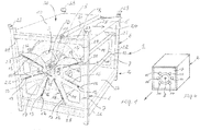
- the present tape reel assembly 1 essentially comprises a frame 2, a tape reel 3 rotatably supported in the frame 2, and a coil 4 wound from a metal tape 5 on the tape reel 3. It should be noted that the reel 4 can also consist of other material tapes.
- the frame 2 comprises two in the longitudinal direction of the band reel assembly 1 opposite, each held on a frame 6 side wall parts 7, in which the longitudinal axis 8 of the band reel 3 is rotatably mounted.
- bearing parts 10 are preferably arranged on the longitudinal axis 8, which are each preferably held in upwardly opening, circular cutouts 9 of the side wall parts 7 in that an annular circumferential groove 11 of each bearing part 10 surrounds the edge region of the respective cutout 9 of the corresponding side wall 7 overlaps.
- FIG. 1 only the bearing part 10, the circumferential groove 11 and the cutout 9 of the front side wall part 7 are shown.
- the corresponding elements of the rear side wall part 7 are formed accordingly. In this way, it is ensured that the band reel 3 together with the bearing parts 10 and the longitudinal axis 8 can be lifted out of the cutouts 9 upwards, for example, manually out of the frame 2.
- a plurality, preferably six guide slots 12 are provided, of which each two opposite in the longitudinal direction of the tape reel 2. In this way it is ensured that in each case a pressure roller 14 is held radially displaceable in a pair of longitudinally opposite guide slots 12 of the two side wall parts 7.
- Each longitudinal axis 13 projects with its end regions beyond its associated side wall parts 7 outwards to the sides facing away from the pressure roller 14.
- Each longitudinal axis 13 is preferably associated along a imaginary extension of the corresponding guide slot 12 radially inwardly a retaining bolt 15, which is fixed in the corresponding side wall part 7 and protrudes to the tape reel 3 opposite side of the side wall part 7 to the outside.
- the illustrated retaining bolts may be arranged radially outside the longitudinal axes of the pressure rollers, which is then not in the spring parts to tension springs, but to compression springs.
- the spring parts and other energy storage are conceivable.
- a handwheel 17 can be pushed in a rotationally fixed manner to at least one end of the longitudinal axis 8 of the band reel 3 that projects beyond a side wall part 7, so that the band reel 3 can be turned manually.
- the frame 2 on its upper side, on which the wound on the coil 4 metal strip 5 can be removed, in the transverse direction, ie, in the direction of the longitudinal axis 8 extending removal opening 18.
- the removal opening 18 joins in the removal direction 25 of the metal strip 5 as seen in a plate-shaped cover member 19, which is part of a cover unit 30 which is detachably arranged on the upper side of the frame 2.
- the cover unit 30 rests on angle parts 29, which are fastened to the frame 2.
- a plate-shaped bottom part 26, which closes the space below the lower pressure rollers 14 downwards, is preferably arranged on the frame 2 and underneath the band reel 3.
- the tape reel 3, z. B. after unwinding of the metal strip 5 and after the removal of the cover unit 30, are lifted up from the frame 2.
- the cutouts 9 in the side wall parts 7 are opened upward in the manner already mentioned, such that the longitudinal axis 8 can preferably be removed together with the bearing parts 10 from the cutouts 9.
- the upper openings of the cutouts 9 are larger than the diameter of the bottoms of the circumferential grooves 11 of the bearing parts 10.
- the upper pinch rollers 14 can be moved completely out of the area of the tape reel 3 against the force of the spring parts 16, at least one of the guide slots 12 assigned to these upper pinch rollers 14 has the opposite one Side wall parts 7 a from the outer end of the guide slot 12 extending downward bending region 31, in which the over the side wall portions 7 protruding free end portions of the longitudinal axes 13 of the upper pinch rollers 14 from the guide slot 12 are movable downwards and locked.
- Other locking devices for the longitudinal axes 13 of said longitudinal axes 13 are conceivable.
- the expediently rectangular frame 6 has on each side preferably two upwardly and upwardly projecting post parts 22, wherein the upper ends of the post parts 22 each have receiving parts 23 in which the lower ends of the post parts 22 '(FIG. FIG. 3 ) of a further frame 2 'of another band reel assembly 1' can be used, which can be arranged above the lower band reel assembly 1.
- the said post parts 22 project respectively downwards over transverse struts 28 fastened to them, so that for raising, lowering and transporting the band reel assembly 1 under the transverse struts 22 opposite the longitudinal axis 8 and extending transversely to the longitudinal axis 8, for example the lifting arms of a forklift or another lifting device can be inserted.
- the already mentioned bottom plate 26 rests on the cross struts 26 or is fixed or integrally connected thereto.
- a plurality of lower band reel assemblies 1 and upper Bandhaspelanordonne 1 'in rows next to and above each other are arranged.
- a Bandhaspelan whatsoever 1 is arranged below a Bandhaspelan whatsoever 1 ', the lower ends of their post parts 22' engage in the receiving parts 23 of the lower band reel assembly 1.
- a removal channel 27 formed by seen in the removal direction 25 each unwound from the coil 4 a rear band reel assembly 1 metal strip 5 can be pushed by turning the band reel 3 to each of the removal direction 25 next front Bandhaspelan kann 1.
- a metal band 5 'of an upper band reel assembly 1' can be unwound from the coil 4 'by rotating the band reel 3' so that it slides below the band reel 3 'due to its inherent rigidity over the bottom part 26' in the withdrawal direction 25 and subsequently over the Bottom part 26 'of each adjacent in the removal direction 25 Bandhaspelan angel 1' is pushed.
- One advantage is that both the metal strip 5 'removed from an upper band reel assembly 1' and the metal band 5 taken from a lower band reel assembly 1 are transported substantially to a plane in which the respective processing takes place. Details of FIG. 3 already related to the FIGS. 1 and 2 are explained in the appropriate way.
Landscapes
- Engineering & Computer Science (AREA)
- Mechanical Engineering (AREA)
- Storage Of Web-Like Or Filamentary Materials (AREA)
Description
Die vorliegende Erfindung betrifft eine Bandhaspelanordnung zum Auf- und/oder Abwickeln eines Materialbandes, insbesondere Metallbandes, nach dem Oberbegriff des Patentanspruches 1 (siehe z.B.
Weitere Bandhaspelanordnungen sind bekannt. Beispielsweise geht aus der
Die Aufgabe der vorliegenden Erfindung besteht darin, eine Bandhaspelanordnung zu schaffen, die ein schlupffreies Auf- und Abwickeln eines Metallbandes sicherstellt und gleichzeitig relativ einfach, kompakt und kostengünstig aufgebaut ist.The object of the present invention is to provide a band reel assembly that ensures a slip-free winding and unwinding of a metal strip and at the same time is relatively simple, compact and inexpensive.
Diese Aufgabe wird durch eine Bandhaspelanordnung mit den Merkmalen des Patentanspruches 1 gelöst. Die erfindungsgemäße Bandhaspelanordnung umfasst demgemäß eine in einem Gestell drehbar angeordnete Bandhaspel, auf der ein Coil eines Materialbandes, insbesondere eines Metallbandes, aufwickelbar ist. Ferner weist die erfindungsgemäße Bandhaspelanordnung Andruckrollen auf, die gegen den Außenumfang des Coils drückbar sind. Die Andruckrollen sind dabei durch Betätigungsvorrichtungen, die außerhalb des Bereiches der Längserstreckung der Bandhaspel angeordnet sind, radial nach innen zur Längsachse der Bandhaspel bewegbar.This object is achieved by a band reel assembly having the features of
Der wesentliche Vorteil der erfindungsgemäßen Bandhaspelanordnung besteht darin, dass sie relativ einfach aufgebaut und daher im Vergleich zu der zuvor erläuterten, bekannten Bandhaspelanordnung vergleichsweise kostengünstig herstellbar ist. Während bei der bekannten Bandhaspelanordnung die hydraulische Betätigungsvorrichtung für die Bandandruckrollen in der Richtung der Längsachse der Bandhaspel gesehen im Bereich der Länge der Bandhaspel angeordnet ist, besteht ein wesentliches Merkmal der vorliegenden Erfindung darin, dass die Andruckrollen der vorliegenden Bandhaspelanordnung durch eine Betätigungsvorrichtung betätigt werden, die außerhalb der genannten Länge der Bandhaspel, d. h. also axial seitlich der Bandhaspel angeordnet ist. Dadurch ist es möglich die gesamte Bandhaspelanordnung insbesondere in radialer Richtung der Bandhaspel gesehen äußerst kompakt und schmalbauend auszuführen. Zudem wird dadurch eine einfache Entnahme der Bandhaspel aus der Bandhaspelanordnung in radialer Richtung nach oben oder in Richtung der Längsachse der Bandhaspel aus der Bandhaspelanordnung ermöglicht.The main advantage of the tape reel assembly according to the invention is that it is relatively simple in construction and therefore comparatively inexpensive to produce in comparison to the previously described, known band reel assembly. While in the known Bandhaspelanordnung the hydraulic actuator for the Bandandruckrollen is arranged in the direction of the longitudinal axis of the tape reel in the region of the length of the tape reel, an essential feature of the present invention is that the pinch rollers of the present tape reel assembly are actuated by an actuator which outside the said length of the tape reel, d. H. that is arranged axially laterally of the band reel. This makes it possible to perform the entire band reel assembly seen in particular in the radial direction of the tape reel extremely compact and slender. In addition, a simple removal of the tape reel from the tape reel assembly in the radial direction upwards or in the direction of the longitudinal axis of the tape reel from the tape reel assembly is made possible.
Bei einer bevorzugten Ausgestaltung der Erfindung weist das Gestell sich in der Längsrichtung der Längsachse der Bandhaspel gegenüberliegende Seitenwandteile auf, in denen die Längsachse der Bandhaspel drehbar gelagert ist. Dabei sind die Betätigungsvorrichtungen an den der Bandhaspel abgewandten Seiten der Seitenwandteile angeordnet. Diese Ausführungsform ermöglicht vorteilhafterweise eine besonders einfache und effektive Anordnung der Betätigungsvorrichtungen an den Seitenwandteilen.In a preferred embodiment of the invention, the frame has in the longitudinal direction of the longitudinal axis of the tape reel opposite side wall parts in which the longitudinal axis of the tape reel is rotatably mounted. The actuators are arranged on the side facing away from the band reel sides of the side wall parts. This embodiment advantageously allows a particularly simple and effective arrangement of the actuators on the side wall parts.
Besonders einfach und montagefreundlich sowie kostengünstig weisen die Betätigungsvorrichtungen die Form von Energiespeichern, vorzugsweise von Federteilen, auf, die die Längsachsen der Andruckrollen in Richtung auf die Längsachse der Bandhaspel ziehen oder drücken.Particularly simple and easy to install and inexpensive, the actuators in the form of energy storage, preferably of spring parts on, pull or push the longitudinal axes of the pressure rollers in the direction of the longitudinal axis of the tape reel.
Eine besonders vorteilhafte Lagerung der Längsachse der Bandhaspel in den Seitenwandteilen wird bei einer Weiterbildung der Erfindung dadurch erreicht, dass sich in der Richtung der Längsachse der Bandhaspel gesehen in den Seitenwandteilen gegenüberliegende Ausnehmungen befinden, in denen die Längsachse der Bandhaspel drehbar angeordnet ist. Die Ausnehmungen besitzen dabei nach oben weisende Öffnungen, durch die die Längsachse der Bandhaspel nach oben aus den Ausnehmungen entnehmbar ist. Durch diese Anordnung wird vorteilhafterweise eine besonders einfache und schnelle Entnahme der Bandhaspel aus dem Gestell ermöglicht.
Die Längsachse kann dabei reibungsarm in zwei Lagerteilen gelagert sein, die in den Ausnehmungen gehalten sind, wobei die Lagerteile zusammen mit der Längsachse der Bandhaspel durch die Öffnungen nach oben entnehmbar sind.A particularly advantageous storage of the longitudinal axis of the tape reel in the side wall parts is achieved in a development of the invention that seen in the direction of the longitudinal axis of the tape reel in the side wall portions opposite recesses are in which the longitudinal axis of the tape reel is rotatably arranged. The recesses have upwardly facing openings through which the longitudinal axis of the band reel up from the Recesses is removable. By this arrangement, a particularly simple and fast removal of the tape reel is advantageously made possible from the frame.
The longitudinal axis can be mounted friction in two bearing parts, which are held in the recesses, wherein the bearing parts can be removed together with the longitudinal axis of the band reel through the openings to the top.
Zur konstruktiv besonders einfachen Führung der Längsachsen der Andruckrollen sind in den Seitenwandteilen jeweils radial zur Längsachse der Bandhaspel verlaufende Führungen vorgesehen, die besonders einfach die Form von radial verlaufenden Führungsschlitzen aufweisen, wobei sich jeweils zwei Führungsschlitze in der Richtung der Längsachse der Bandhaspel gegenüberliegen und eine Längsachse einer Andruckrolle aufnehmen.For structurally particularly simple guidance of the longitudinal axes of the pressure rollers in the side wall portions each radially to the longitudinal axis of the band reel extending guides are provided, which are particularly simple in the form of radially extending guide slots, wherein each two guide slots in the direction of the longitudinal axis of the band reel and a longitudinal axis pick up a pinch roller.
Wenn die Betätigungsvorrichtungen die Form von Energiespeichern, vorzugsweise in der Form von Federteilen, aufweisen, ist zur einfachen mechanischen Anordnung bzw. Befestigung derselben an den Seitenwandteilen an der radial inneren oder äußeren Seite jedes Führungsschlitzes ein Halteteil, vorzugsweise in der Form eines über die der Bandhaspel abgewandte Seite des entsprechenden Seitenwandteiles vorstehenden Haltebolzens, angeordnet. Die Längsachsen der Andruckrollen stehen dabei jeweils über die der Bandhaspel abgewandte Seite des entsprechenden Seitenwandteiles über, wobei zwischen einem Halteteil und einem überstehenden Bereich der Längsachse der Andruckrolle wenigstens ein die Längsachse der Andruckrolle in Richtung auf die Bandhaspel ziehendes oder drückendes Federteil angeordnet ist. Um eine Entnahme der Bandhaspel aus dem Gestell zu ermöglichen weisen die äußeren Enden der oberen Führungsschlitze sich nach unten erstreckende Abwinkelungen auf. In diesen Abwinkelungen können die Enden der Längsachsen der oberen, in den Entnahmebereich hineinragenden Andruckrollen arretiert werden, um die Andruckrollen zur Entnahme der Bandhaspel während des Entnahmevorganges dauerhaft aus dem Bereich der Bandhaspel zu entfernen.When the actuators are in the form of energy storage devices, preferably in the form of spring members, for ease of mechanical attachment to the sidewall members on the radially inner or outer side of each guide slot, a retaining member, preferably in the form of one over the band winder opposite side of the corresponding side wall part projecting retaining bolt, arranged. The longitudinal axes of the pressure rollers are in each case beyond the tape reel side facing away from the corresponding side wall part, wherein between a holding part and a protruding portion of the longitudinal axis of the pressure roller at least one longitudinal axis of the pressure roller in the direction of the tape reel pulling or pushing spring member is arranged. To allow removal of the tape reel from the frame, the outer ends of the upper guide slots have downwardly extending bends. In these bends, the ends of the longitudinal axes of the upper, protruding into the removal area pinch rollers can be locked to permanently remove the pinch rollers for removing the tape reel during the removal process from the area of the tape reel.
Bei einer besonders vorteilhaften Ausgestaltung der Erfindung umfasst das Gestell vier seitliche, vertikale Pfostenteile, von denen jeweils zwei mit einem Seitenwandteil verbunden sind, und vier untere Querstreben, die mit den Pfostenteile zu dem rechteckigen Gestell verbunden sind. Dadurch wird erreicht, dass die vorliegende Bandhaspelanordnung besonders einfach transportiert werden kann, wenn unter zwei sich gegenüberliegende Querstreben die Hubarme eines Gabelstaplers oder dergleichen geschoben werden.In a particularly advantageous embodiment of the invention, the frame comprises four lateral, vertical post parts, two of which are each connected to a side wall part, and four lower crossbars, with the post parts to the rectangular Frame are connected. It is thereby achieved that the present tape reeling arrangement can be transported in a particularly simple manner when the lifting arms of a forklift or the like are pushed under two mutually opposite transverse struts.
Zum manuellen Drehen der Bandhaspel ist es vorteilhaft, wenn auf wenigsten einem, über ein Seitenwandteil vorstehenden Endbereich der Längsachse der Bandhaspel ein Handrad drehfest befestigbar ist.For manual rotation of the tape reel, it is advantageous if at least one, over a side wall part projecting end portion of the longitudinal axis of the tape reel, a handwheel is rotatably fastened.
Das Gestell weist bei einer weiteren vorteilhaften Ausgestaltung der Erfindung oberhalb der Bandhaspel ein abnehmbares Abdeckteil auf, das die Form einer in der Förderebene des Materialbandes angeordneten Platte besitzt, der in der Entnahmerichtung des Metallbandes gesehen eine Entnahmeöffnung vorgelagert ist, durch die das freie Ende des Materialbandes des Coils nach außen entnehmbar ist. Alternativ weist das Gestell oberhalb der Bandhaspel ein abnehmbares Abdeckteil auf, das parallel zur Längsachse der Bandhaspel verlaufende Rollenteile umfasst, die in der Entnahmerichtung des Metallbandes in der Förderebene des Metallbandes voneinander beabstandet sind, und denen in der Entnahmerichtung des Metallbandes gesehen eine Entnahmeöffnung vorgelagert ist, durch die das freie Ende des Metallbandes des Coils nach außen entnehmbar ist.The frame has in a further advantageous embodiment of the invention above the tape reel on a removable cover, which has the shape of a arranged in the conveying plane of the material strip plate, which is seen in the removal direction of the metal strip precedes a removal opening through which the free end of the material strip of the coil is removable to the outside. Alternatively, the frame above the band reel on a removable cover, which comprises parallel to the longitudinal axis of the band reel extending roller parts, which are spaced apart in the removal direction of the metal strip in the conveying plane of the metal strip, and which is seen in the removal direction of the metal strip preceded by a removal opening, by the free end of the metal strip of the coil can be removed to the outside.
Zudem sollen mehrere derartige Bandhaspelanordnungen zu einer Magazinanordnung kombinierbar sein, die die Aufbewahrung mehrerer Coils aus Metallbändern unterschiedlicher Formen und Materialien ermöglicht. Dabei sollen die Bandhaspeln nach dem Abwickeln der Coils den entsprechenden Bandhaspelanordnungen jeweils einfach entnehmar und durch mit Coils bestückte Bandhaspeln ersetzbar sein.In addition, several such Bandhaspelanordnungen should be combined to form a magazine assembly that allows the storage of multiple coils of metal bands of different shapes and materials. In this case, the tape reels after unwinding of the coils the respective Bandhaspelanordnungen each entnehmar easy and be replaced by coils equipped with tape reels.
Dabei umfasst diese Magazinanordnung mehrere nebeneinander und/oder übereinander angeordnete Bandhaspelanordnungen, derart, dass das von einem Coil einer Bandhaspelanordnung abgewickelte freie Ende eines Metallbandes in der Entnahmerichtung gesehen beim Drehen der Bandhaspel der Bandhaspelanordnung jeweils über das oberhalb des Coils einer neben der Bandhaspelanordnung angeordneten weiteren Bandhaspelanordnung vorgesehene Abdeckteil schiebbar ist.In this case, this magazine arrangement comprises a plurality of juxtaposed and / or superimposed Bandhaspelanordnungen, such that the unwound from a coil of a band reel assembly unwinded end of a metal strip seen in the removal direction when turning the band reel of Bandhaspelanordnung each above the coil of a next to the Bandhaspelanordnung arranged further Bandschaspelanordnung provided cover is pushed.
Die von den Coils der einzelnen Bandhaspelanordnungen der Magazinanordnung abgewickelten Material- bzw. Metallbänder sollen jeweils über die ihnen in der Entnahmerichtung in einer Reihe von Bandhaspelanordnungen jeweils vorgelagerten Bandhaspelanordnungen beim Drehen der jeweiligen Bandhaspelanordnung schlupffrei zur Entnahmeseite der Magazinanordnung vorschiebbar sein. Das Verschieben beim Drehen der Bandhaspel wird dabei durch die Eigensteifigkeit des Metallbandes ermöglicht. Nach dem Abwickeln einer gewünschten Bandlänge von einem Coil soll das Metallband entgegen der Entnahmerichtung wieder schlupffrei auf das Coil aufwickelbar sein.The unwound from the coils of the individual Bandhaspelanordnungen the magazine assembly material or metal bands are each about the them in the removal direction in a series of Bandhaspelanordnungen each upstream Bandhaspelanordnungen when rotating the respective Bandhaspelanordnung without slip to the removal side of the magazine assembly be advanced. The displacement during rotation of the tape reel is made possible by the inherent rigidity of the metal strip. After unwinding a desired length of tape from a coil, the metal strip against the removal direction again without slippage on the coil be wound up.
Ferner betrifft die Erfindung eine solche Magazinanordnung, bei der unterhalb der Bandhaspel einer Bandhaspelanordnung ein Bodenteil angeordnet ist, über das das freie Ende des Metallbandes des auf der Bandhaspel der Bandhaspelanordnung aufgewickelten Coils in der Entnahmerichtung gesehen beim Drehen der Bandhaspel der Bandhaspelanordnung zum Bodenteil einer neben der Bandhaspelanordnung angeordneten weiteren Bandhaspelanordnung schiebbar ist.Furthermore, the invention relates to such a magazine arrangement in which below the band reel of a band reel assembly, a bottom part is arranged, over which the free end of the metal strip of wound on the tape reel of the tape reel assembly coils seen in the removal direction when rotating the tape reel of the tape reel assembly to the bottom part next to the Bandhaspelanordnung arranged further Bandschaspelanordnung is pushed.
Im Folgenden werden die Erfindung und deren Ausgestaltungen im Zusammenhang mit den Figuren näher erläutert. Es zeigen:
-
Figur 1 -
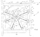
Figur 2 eine Seitenansicht der Bandhaspelanordnung derFigur 1 -
Figur 3 eine Seitenansicht einer Magazinanordnung, bei der beispielsweise vier erfindungsgemäße Bandhaspelanordnungen neben- und übereinander angeordnet sind, und -
Figur 4
-
FIG. 1 in a perspective view of a preferred embodiment of the band reel assembly according to the invention seen from the front, -
FIG. 2 a side view of the band reel assembly ofFIG. 1 . -
FIG. 3 a side view of a magazine assembly in which, for example, four tape reel assemblies according to the invention are arranged side by side and one above the other, and -
FIG. 4 a development of the invention.
Gemäß
Das Gestell 2 umfasst zwei sich in der Längsrichtung der Bandhaspelanordnung 1 gegenüberliegende, jeweils an einem Rahmen 6 gehaltene Seitenwandteile 7, in denen die Längsachse 8 der Bandhaspel 3 drehbar gelagert ist. Zu diesem Zweck sind auf der Längsachse 8 vorzugsweise Lagerteile 10 angeordnet, die jeweils in sich nach oben öffnenden, kreisförmigen Ausschnitten 9 der Seitenwandteile 7 vorzugsweise dadurch gehalten sind, dass eine ringförmige Umfangsnut 11 jedes Lagerteiles 10 den Randbereich des jeweiligen Ausschnittes 9 der entsprechenden Seitenwand 7 übergreift. Es wird darauf hingewiesen, dass in der
Im Folgenden wird eine bevorzugte Betätigungsvorrichtung zur Betätigung der Andruckrollen 14 der vorliegenden Bandhaspelanordnung 1 näher erläutert. In den Seitenwandteilen 7 sind dabei sich gegenüberliegend radial zur Längsachse 8 verlaufende Führungsschlitze 12 angeordnet, in denen die jeweiligen Längsachsen 13 der Andruckrollen 14 verschiebbar gehalten sind. Auf diese Weise wird sichergestellt, dass die Andruckrollen 14 jeweils von außen her radial nach innen bewegt werden können, derart, dass sie am Außenumfang des auf der Bandhaspel 3 angeordneten Coils 4 anliegen.In the following, a preferred actuator for actuating the
In den Seitenwandteilen 7 sind mehrere, vorzugsweise sechs Führungsschlitze 12 vorgesehen, von denen sich jeweils zwei in der Längsrichtung der Bandhaspel 2 gegenüberliegen. Auf diese Weise wird sichergestellt, dass jeweils eine Andruckrolle 14 in einem Paar von sich in der Längsrichtung gegenüberliegenden Führungsschlitzen 12 der beiden Seitenwandteile 7 radial verschiebbar gehalten wird. Jede Längsachse 13 steht mit ihren Endbereichen über die ihr zugeordneten Seitenwandteile 7 nach außen zu den der Andruckrolle 14 abgewandten Seiten vor.In the side wall parts 7 a plurality, preferably six
Jeder Längsachse 13 ist vorzugsweise entlang einer gedachten Verlängerung des entsprechenden Führungsschlitzes 12 radial innenliegend ein Haltebolzen 15 zugeordnet, der in dem entsprechenden Seitenwandteil 7 befestigt ist und zu der der Bandhaspel 3 gegenüberliegenden Seite des Seitenwandteiles 7 nach außen vorsteht.Each
Da die in den Führungsschlitzen 12 angeordneten Längsachsen 13 der Andruckrollen 14 ebenfalls nach außen über das Seitenwandteil 7 vorstehen, kann zwischen jeweils einem Haltebolzen 15 und einem überstehenden Bereich der Längsachse 13 einer Andruckrolle 14 wenigstens ein Federteil 16 in der Form einer Zugfeder angeordnet werden, sodass die einer Andruckrolle 14 zugeordneten überstehenden Bereiche in den entsprechenden Führungsschlitzen 12 durch die Federteile 16 radial nach innen gezogen werden, derart, dass die Andruckrolle 14 gegen den Außenumfang des Coils 4 gezogen wird. Vorzugsweise sind derartige Haltebolzen 15 und Federteile 16 jeweils an den sich gegenüberliegenden Seitenwandteilen 7 angeordnet. Gemäß
Um größere Federkräfte zu erhalten, können jedoch jeweils auch mehrere, z. B. zwei Federteile parallel geschaltet und zwischen den entsprechenden Haltebolzen 15 und überstehenden Bereichen der Längsachsen 13 angeordnet sein.Since arranged in the
In order to obtain greater spring forces, but also several, z. B. two spring parts connected in parallel and between the corresponding retaining
Andere Ausgestaltungen der Federteile sind denkbar. Beispielsweise können die erläuterten Haltebolzen radial außerhalb der Längsachsen der Druckrollen angeordnet sein, wobei es sich dann bei den Federteilen nicht um Zugfedern, sonder um Druckfedern handelt. Anstelle der Federteile sind auch andere Energiespeicher denkbar.Other embodiments of the spring parts are conceivable. For example, the illustrated retaining bolts may be arranged radially outside the longitudinal axes of the pressure rollers, which is then not in the spring parts to tension springs, but to compression springs. Instead of the spring parts and other energy storage are conceivable.
In der aus der
In der aus den
In der aus den
Um es zu ermöglichen, dass zur Entnahme der Bandhaspel 3 aus dem Gestell 2 die oberen Andruckrollen 14 vollständig aus dem Bereich der Bandhaspel 3 gegen die Kraft der Federteile 16 herausbewegt werden können, weist wenigstens einer der diesen oberen Andruckrollen 14 zugeordneten Führungsschlitze 12 der sich gegenüberliegenden Seitenwandteile 7 einen vom äußeren Ende des Führungsschlitzes 12 nach unten verlaufenden Abwinkelungsbereich 31 auf, in dem die über die Seitenwandteile 7 überstehenden freien Endbereiche der Längsachsen 13 der oberen Andruckrollen 14 vom Führungsschlitz 12 aus nach unten bewegbar und arretierbar sind. Andere Arretierungsvorrichtungen für die Längsachsen 13 der genannten Längsachsen 13 sind denkbar.To make it possible for the tape reel 3 to be removed from the frame 2, the
In der Entnahmerichtung 25 gesehen weist die Bandhaspelanordung 1 ein sich in Längsrichtung 8 erstreckendes Rollenteil 21 an der der Entnahmeöffnung 18 zugewandten Seite des Abdeckteiles 19 auf, das vorzugsweise an den entsprechenden Seiten der Abdeckeinheit 30 drehbar gehalten ist. Die Funktion dieses Rollenteiles 21 wird weiter unten näher erläutert. Es ist auch denkbar, das erläuterte Abdeckteil 19 durch senkrecht zur Längsachse 8 voneinander beabstandete, drehbar an der Abdeckeinheit 30 angeordnete Rollenteile zu ersetzen, deren Längsachsen parallel zur Längsachse 8 verlaufen.Seen in the
Der zweckmäßigerweise rechteckig ausgebildete Rahmen 6 besitzt an jeder Seite vorzugsweise zwei nach unten und oben vorstehende Pfostenteile 22, wobei die oberen Enden der Pfostenteile 22 jeweils Aufnahmeteile 23 besitzen, in denen die unteren Enden der Pfostenteile 22' (
Es können gemäß
In der aus der
Es ist denkbar oberhalb der genannten oberen Reihe der Bandhaspelanordnungen 1' weitere Reihen von Bendhaspelanordnungen in der beschriebenen Weise anzuordnen.It is conceivable to arrange further rows of Bendhaspelanordnungen in the manner described above the said upper row of Bandhaspelanordnungen 1 '.
Wenn eine Bandhaspelanordnung 1 oder 1' leer ist, kann sie mit der Hilfe eines Hebegerätes angehoben und aus der entsprechenden Reihe der Bandhaspelanordnungen 1, 1' herausgezogen werden. An ihre Stelle kann dann, ggf. nach dem Herabsetzen einer oberen Bandhaspelanordnung 1' nach unten, eine volle Bandhaspelanordnung mit dem Hebegerät eingesetzt werden.When a
Im Folgenden wird im Zusammenhang mit der
- 11
- BandhaspelanordnungTape reel assembly
- 22
- Gestellframe
- 33
- Bandhaspelstrip coiler
- 44
- Coilcoil
- 55
- Metallbandmetal band
- 66
- Rahmenframe
- 77
- SeitenwandteilSidewall portion
- 88th
- Längsachselongitudinal axis
- 99
- Ausschnittneckline
- 1010
- Lagerteilbearing part
- 1111
- Umfangsnutcircumferential groove
- 1212
- Führungsschlitzguide slot
- 1313
- Längsachselongitudinal axis
- 1414
- Andruckrollepinch
- 1515
- Haltebolzenretaining bolt
- 1616
- Federteilspring part
- 1717
- Handradhandwheel
- 1818
- Entnahmeöffnungremoval opening
- 1919
- Abdeckteilcover
- 2020
- Querstrebecrossmember
- 2121
- Rollenteilroller part
- 2222
- Pfostenteilpost part
- 2323
- Aufnahmeteilreceiving part
- 2424
- freies Endefree end
- 2525
- Entnahmerichtungremoval direction
- 2626
- Bodenteilthe bottom part
- 2727
- Entnahmekanalremoval channel
- 2828
- Querstrebecrossmember
- 2929
- Winkelteilangle part
- 3030
- Abdeckeinheitcapping
- 3131
- AbwinkelungsbereichAbwinkelungsbereich
Claims (13)
- A tape reel assembly having a tape reel (3) rotatably arranged in a frame (2), onto which a coil (4) of a material web, in particular a metal strip (5) is windable, and having pressure rollers (14), which are pressable against the outer periphery of the coil (4) by actuating devices (13, 16), wherein the pressure rollers (14) are movable by the actuating devices (13, 16) in a radially inward direction toward the longitudinal axle (8) of the tape reel (3), characterized in that the actuating devices (13 , 16) are arranged outside the area of the longitudinal extension of the tape reel (3).
- The tape reel assembly according to claim 1, characterized in that the frame (2) has side wall members (7) opposing one another in the longitudinal direction of the longitudinal axle (8) of the tape reel (3), wherein the longitudinal axle (8) of the tape reel (3) is rotatably mounted, and that the actuating devices are arranged on the sides of the side wall elements (7) facing away from the tape reel (3).
- The tape reel assembly according to claim 2, characterized in that the actuating devices take the form of energy stores, preferably of spring members (16), which pull or push the longitudinal axes of the pressure rollers (14) in the direction towards the longitudinal axle (8) of the tape reel (3).
- The tape reel assembly according to claim 2 or 3, characterized in that recesses (9) are arranged in the side wall elements (7), opposing each other in the direction of the longitudinal axis (8) of the tape reel (3), wherein the longitudinal axis (8) of the tape reel (3 is) rotatably arranged, wherein the recesses (9) have upwardly facing openings through which the longitudinal axle (8) is upwardly removable from the recesses (9).
- The tape reel assembly according to claim 4, characterized in that the longitudinal axle (8) is mounted in two bearing members (10), which are supported in the recesses (9), wherein the bearing members (9) are upwardly removable through the openings.
- The tape reel assembly according to one of claims 2 to 5, characterized in that the side wall elements (7) each have guides, preferably in the form of guide slots (12), extending radially with respect to the longitudinal axle (8) of the tape reel (3), of which two each oppose each other in the direction of the longitudinal axle (8) of the tape reel (3) and receive a longitudinal axle (13) of a pressure roller (14).
- The tape reel assembly according to claim 6, characterized in that a support member, preferably in the form of a holding pin (15) projecting over the side of the corresponding side wall element (7) facing away from the tape reel (3), is arranged on the radially inner or outer side of each guide slot (12) such that the longitudinal axles (13) of the pressure rollers (14) each project over the side of the corresponding side wall element (7) facing away from the tape reel (3) and that at least one spring member (16) is arranged between a support member and a protruding region of the longitudinal axle (13) of the pressure roller (14), pulling or pushing said longitudinal axle (13) of the pressure roller (14) in the direction towards of the tape reel (3).
- The tape reel assembly according to claim 6 or 7, characterized in that the outer ends of the upper guide slots (13) have downwardly extending angulations (31), in which the ends of the longitudinal axles (13) of the upper pressure rollers (14) are lockable.
- The tape reel assembly according to any one of claims 1 to 8, characterized in that the frame (2) comprises four lateral, vertical post members (22), of which two each are connected with a side wall element (7), and four lower transverse struts (28), which are connected with the post members (22) to form the rectangular frame (2).
- The tape reel assembly according to any one of claims 1 to 9, characterized in that, at least on one end region projecting over a side wall element (7) of the longitudinal axle (8) of the tape reel (3), a hand wheel (17) for rotating the tape reel (3) is torque-proof attachable.
- The tape reel assembly according to any one of claims 1 to 10, characterized in that the frame (2) has a removable cover member (30) above the band reel (3), which has the shape of a plate arranged in the conveying plane of the metal strip (5), upstream of which, viewed from the removal direction (25) of the metal strip (5), a removal opening (18) is arranged, through which the free end (24) of the metal strip (5) of the coil (4) is removable, or that
the frame (2) has a removable cover member (30) above the band reel (3) which comprises roller elements extending parallel to the longitudinal axle (8) of the tape reel (3), which are spaced apart in the removal direction (25) of the metal strip (5) in the conveying plane of the metal strip (5), and upstream of which, viewed from the removal direction (25) of the metal strip (5), a removal opening (18) is arranged, through which the free end (24) of the metal strip (5) of the coil (4) is removable. - A magazine arrangement consisting of several juxtaposed and/or superposed tape reel assemblies (1) according to claim 11, characterized in that the free end (24) of a metal strip (5) unwound from a coil (4) of a tape reel assembly (1) is respectively slidable in the removal direction (25), viewed during rotation of the tape reel (3) of said tape reel assembly (1), over the cover member (30), provided above the coil (4) of a further tape reel assembly arranged next to the tape reel assembly (1).
- Magazine arrangement according to claim 12, characterized in that a bottom member (26) is arranged below the tape reel (3) of a tape reel assembly (1), over which the free end (24) of the metal strip (5) of the coil (4) wound on the tape reel (3) of the tape reel assembly (1) is slidable, in the removal direction (25), viewed during rotation of the tape reel (3) of the tape reel assembly (1) toward the bottom member of a further tape reel assembly arranged next to the tape reel assembly (1).
Applications Claiming Priority (1)
| Application Number | Priority Date | Filing Date | Title |
|---|---|---|---|
| DE102013106274.1A DE102013106274A1 (en) | 2013-06-17 | 2013-06-17 | Bandhaspelanordnung for winding and / or unwinding a metal strip |
Publications (2)
| Publication Number | Publication Date |
|---|---|
| EP2829333A1 EP2829333A1 (en) | 2015-01-28 |
| EP2829333B1 true EP2829333B1 (en) | 2017-05-03 |
Family
ID=50933019
Family Applications (1)
| Application Number | Title | Priority Date | Filing Date |
|---|---|---|---|
| EP14172015.1A Active EP2829333B1 (en) | 2013-06-17 | 2014-06-11 | Tape reel arrangement for winding and/or unwinding a metal strip |
Country Status (2)
| Country | Link |
|---|---|
| EP (1) | EP2829333B1 (en) |
| DE (1) | DE102013106274A1 (en) |
Families Citing this family (2)
| Publication number | Priority date | Publication date | Assignee | Title |
|---|---|---|---|---|
| CN111515266B (en) * | 2020-05-28 | 2021-02-05 | 三铃制线(东莞)有限公司 | Alloy wire winding method |
| CN112252016B (en) * | 2020-09-27 | 2023-04-28 | 肥东国喜箱包有限公司 | Case and bag surface fabric guillootine |
Family Cites Families (5)
| Publication number | Priority date | Publication date | Assignee | Title |
|---|---|---|---|---|
| US2725104A (en) * | 1951-06-15 | 1955-11-29 | Kaiser Aluminium Chem Corp | Coiling apparatus |
| DE2264587B2 (en) * | 1972-03-24 | 1976-06-10 | WINDING DEVICE FOR TAPES OR FILMS | |
| DE2613453A1 (en) * | 1976-03-30 | 1977-10-13 | Bernhard Bruene | Coiling machine for metal foil - is designed to eliminate vibrational stresses causing deformation of the foil |
| DE3910991A1 (en) * | 1989-04-05 | 1990-10-11 | Schloemann Siemag Ag | METHOD FOR WINDING TAPES IN REELING PLANTS |
| DE102009029918A1 (en) | 2009-04-09 | 2010-10-14 | Hpl-Neugnadenfelder Maschinenfabrik Gmbh | Anwickelhilfe, tape reel and rolling device |
-
2013
- 2013-06-17 DE DE102013106274.1A patent/DE102013106274A1/en not_active Withdrawn
-
2014
- 2014-06-11 EP EP14172015.1A patent/EP2829333B1/en active Active
Non-Patent Citations (1)
| Title |
|---|
| None * |
Also Published As
| Publication number | Publication date |
|---|---|
| DE102013106274A1 (en) | 2014-12-18 |
| EP2829333A1 (en) | 2015-01-28 |
Similar Documents
| Publication | Publication Date | Title |
|---|---|---|
| EP2516081B1 (en) | Support for a metal coil and apparatuses comprising such a support | |
| EP0281942A1 (en) | Wire removing machine | |
| AT517387A1 (en) | Bending tool storage device | |
| EP2500294A1 (en) | Roller conveyor for transporting piece goods, e.g. pallets or crates | |
| EP2829333B1 (en) | Tape reel arrangement for winding and/or unwinding a metal strip | |
| DE102014001779A1 (en) | Device for storing filament bobbins | |
| EP2636622B1 (en) | Turret winder of a cast film system | |
| EP1171725B1 (en) | Transporting device | |
| EP3585529B1 (en) | Device and method for transporting a coil | |
| DE3809496A1 (en) | Ring-winding apparatus and process for the winding of winding material to form wound rings | |
| EP3291926B1 (en) | System, coil transport vehicle and method for discharging a coil wound on a winding system | |
| DE102010054142B4 (en) | Arrangement and method for removing at least one metal strip collar from a coiler mandrel of a take-up reel | |
| WO1999057052A1 (en) | Device for manipulating a bobbin in a winder | |
| DE102017111416B4 (en) | Winding shaft for a nonwoven winder and intended nonwoven winder | |
| DE102009026208B4 (en) | Cable drums for mobile television production units | |
| DE102011008639B4 (en) | Winding sleeve for reeling strip-shaped products | |
| EP0223938B1 (en) | Abrasive belt storage | |
| DE202010011441U1 (en) | mast system | |
| DE4009041C2 (en) | Device for winding webs of goods | |
| EP3715512B1 (en) | Warp beam assembly | |
| DE19900086A1 (en) | Laminate web roll | |
| DE202015105036U1 (en) | Handling of rollers, in particular axially juxtaposed rollers | |
| DE19927921B4 (en) | Hurdle board for sheetfed presses | |
| DE102016006724A1 (en) | Vehicle with a carrier organization system | |
| DE102017111335B4 (en) | Device for transporting a winding roller in a fleece winder |
Legal Events
| Date | Code | Title | Description |
|---|---|---|---|
| 17P | Request for examination filed |
Effective date: 20140611 |
|
| AK | Designated contracting states |
Kind code of ref document: A1 Designated state(s): AL AT BE BG CH CY CZ DE DK EE ES FI FR GB GR HR HU IE IS IT LI LT LU LV MC MK MT NL NO PL PT RO RS SE SI SK SM TR |
|
| AX | Request for extension of the european patent |
Extension state: BA ME |
|
| PUAI | Public reference made under article 153(3) epc to a published international application that has entered the european phase |
Free format text: ORIGINAL CODE: 0009012 |
|
| R17P | Request for examination filed (corrected) |
Effective date: 20150428 |
|
| RBV | Designated contracting states (corrected) |
Designated state(s): AL AT BE BG CH CY CZ DE DK EE ES FI FR GB GR HR HU IE IS IT LI LT LU LV MC MK MT NL NO PL PT RO RS SE SI SK SM TR |
|
| GRAP | Despatch of communication of intention to grant a patent |
Free format text: ORIGINAL CODE: EPIDOSNIGR1 |
|
| RIC1 | Information provided on ipc code assigned before grant |
Ipc: B21C 47/06 20060101AFI20161027BHEP Ipc: B65H 18/26 20060101ALI20161027BHEP Ipc: B65H 75/00 20060101ALI20161027BHEP Ipc: B65H 18/02 20060101ALI20161027BHEP Ipc: B21C 47/32 20060101ALI20161027BHEP |
|
| INTG | Intention to grant announced |
Effective date: 20161123 |
|
| GRAJ | Information related to disapproval of communication of intention to grant by the applicant or resumption of examination proceedings by the epo deleted |
Free format text: ORIGINAL CODE: EPIDOSDIGR1 |
|
| GRAP | Despatch of communication of intention to grant a patent |
Free format text: ORIGINAL CODE: EPIDOSNIGR1 |
|
| INTC | Intention to grant announced (deleted) | ||
| GRAS | Grant fee paid |
Free format text: ORIGINAL CODE: EPIDOSNIGR3 |
|
| INTG | Intention to grant announced |
Effective date: 20170227 |
|
| GRAA | (expected) grant |
Free format text: ORIGINAL CODE: 0009210 |
|
| AK | Designated contracting states |
Kind code of ref document: B1 Designated state(s): AL AT BE BG CH CY CZ DE DK EE ES FI FR GB GR HR HU IE IS IT LI LT LU LV MC MK MT NL NO PL PT RO RS SE SI SK SM TR |
|
| REG | Reference to a national code |
Ref country code: GB Ref legal event code: FG4D Free format text: NOT ENGLISH |
|
| REG | Reference to a national code |
Ref country code: AT Ref legal event code: REF Ref document number: 889405 Country of ref document: AT Kind code of ref document: T Effective date: 20170515 Ref country code: CH Ref legal event code: EP |
|
| REG | Reference to a national code |
Ref country code: IE Ref legal event code: FG4D Free format text: LANGUAGE OF EP DOCUMENT: GERMAN |
|
| REG | Reference to a national code |
Ref country code: DE Ref legal event code: R096 Ref document number: 502014003611 Country of ref document: DE |
|
| REG | Reference to a national code |
Ref country code: NL Ref legal event code: MP Effective date: 20170503 |
|
| REG | Reference to a national code |
Ref country code: LT Ref legal event code: MG4D |
|
| PG25 | Lapsed in a contracting state [announced via postgrant information from national office to epo] |
Ref country code: GR Free format text: LAPSE BECAUSE OF FAILURE TO SUBMIT A TRANSLATION OF THE DESCRIPTION OR TO PAY THE FEE WITHIN THE PRESCRIBED TIME-LIMIT Effective date: 20170804 Ref country code: HR Free format text: LAPSE BECAUSE OF FAILURE TO SUBMIT A TRANSLATION OF THE DESCRIPTION OR TO PAY THE FEE WITHIN THE PRESCRIBED TIME-LIMIT Effective date: 20170503 Ref country code: ES Free format text: LAPSE BECAUSE OF FAILURE TO SUBMIT A TRANSLATION OF THE DESCRIPTION OR TO PAY THE FEE WITHIN THE PRESCRIBED TIME-LIMIT Effective date: 20170503 Ref country code: LT Free format text: LAPSE BECAUSE OF FAILURE TO SUBMIT A TRANSLATION OF THE DESCRIPTION OR TO PAY THE FEE WITHIN THE PRESCRIBED TIME-LIMIT Effective date: 20170503 Ref country code: NO Free format text: LAPSE BECAUSE OF FAILURE TO SUBMIT A TRANSLATION OF THE DESCRIPTION OR TO PAY THE FEE WITHIN THE PRESCRIBED TIME-LIMIT Effective date: 20170803 Ref country code: FI Free format text: LAPSE BECAUSE OF FAILURE TO SUBMIT A TRANSLATION OF THE DESCRIPTION OR TO PAY THE FEE WITHIN THE PRESCRIBED TIME-LIMIT Effective date: 20170503 |
|
| PG25 | Lapsed in a contracting state [announced via postgrant information from national office to epo] |
Ref country code: BG Free format text: LAPSE BECAUSE OF FAILURE TO SUBMIT A TRANSLATION OF THE DESCRIPTION OR TO PAY THE FEE WITHIN THE PRESCRIBED TIME-LIMIT Effective date: 20170803 Ref country code: IS Free format text: LAPSE BECAUSE OF FAILURE TO SUBMIT A TRANSLATION OF THE DESCRIPTION OR TO PAY THE FEE WITHIN THE PRESCRIBED TIME-LIMIT Effective date: 20170903 Ref country code: SE Free format text: LAPSE BECAUSE OF FAILURE TO SUBMIT A TRANSLATION OF THE DESCRIPTION OR TO PAY THE FEE WITHIN THE PRESCRIBED TIME-LIMIT Effective date: 20170503 Ref country code: NL Free format text: LAPSE BECAUSE OF FAILURE TO SUBMIT A TRANSLATION OF THE DESCRIPTION OR TO PAY THE FEE WITHIN THE PRESCRIBED TIME-LIMIT Effective date: 20170503 Ref country code: RS Free format text: LAPSE BECAUSE OF FAILURE TO SUBMIT A TRANSLATION OF THE DESCRIPTION OR TO PAY THE FEE WITHIN THE PRESCRIBED TIME-LIMIT Effective date: 20170503 Ref country code: LV Free format text: LAPSE BECAUSE OF FAILURE TO SUBMIT A TRANSLATION OF THE DESCRIPTION OR TO PAY THE FEE WITHIN THE PRESCRIBED TIME-LIMIT Effective date: 20170503 Ref country code: PL Free format text: LAPSE BECAUSE OF FAILURE TO SUBMIT A TRANSLATION OF THE DESCRIPTION OR TO PAY THE FEE WITHIN THE PRESCRIBED TIME-LIMIT Effective date: 20170503 |
|
| PG25 | Lapsed in a contracting state [announced via postgrant information from national office to epo] |
Ref country code: EE Free format text: LAPSE BECAUSE OF FAILURE TO SUBMIT A TRANSLATION OF THE DESCRIPTION OR TO PAY THE FEE WITHIN THE PRESCRIBED TIME-LIMIT Effective date: 20170503 Ref country code: DK Free format text: LAPSE BECAUSE OF FAILURE TO SUBMIT A TRANSLATION OF THE DESCRIPTION OR TO PAY THE FEE WITHIN THE PRESCRIBED TIME-LIMIT Effective date: 20170503 Ref country code: CZ Free format text: LAPSE BECAUSE OF FAILURE TO SUBMIT A TRANSLATION OF THE DESCRIPTION OR TO PAY THE FEE WITHIN THE PRESCRIBED TIME-LIMIT Effective date: 20170503 Ref country code: SK Free format text: LAPSE BECAUSE OF FAILURE TO SUBMIT A TRANSLATION OF THE DESCRIPTION OR TO PAY THE FEE WITHIN THE PRESCRIBED TIME-LIMIT Effective date: 20170503 Ref country code: RO Free format text: LAPSE BECAUSE OF FAILURE TO SUBMIT A TRANSLATION OF THE DESCRIPTION OR TO PAY THE FEE WITHIN THE PRESCRIBED TIME-LIMIT Effective date: 20170503 |
|
| REG | Reference to a national code |
Ref country code: DE Ref legal event code: R097 Ref document number: 502014003611 Country of ref document: DE |
|
| PG25 | Lapsed in a contracting state [announced via postgrant information from national office to epo] |
Ref country code: SM Free format text: LAPSE BECAUSE OF FAILURE TO SUBMIT A TRANSLATION OF THE DESCRIPTION OR TO PAY THE FEE WITHIN THE PRESCRIBED TIME-LIMIT Effective date: 20170503 Ref country code: IT Free format text: LAPSE BECAUSE OF FAILURE TO SUBMIT A TRANSLATION OF THE DESCRIPTION OR TO PAY THE FEE WITHIN THE PRESCRIBED TIME-LIMIT Effective date: 20170503 |
|
| PLBE | No opposition filed within time limit |
Free format text: ORIGINAL CODE: 0009261 |
|
| STAA | Information on the status of an ep patent application or granted ep patent |
Free format text: STATUS: NO OPPOSITION FILED WITHIN TIME LIMIT |
|
| REG | Reference to a national code |
Ref country code: IE Ref legal event code: MM4A |
|
| REG | Reference to a national code |
Ref country code: FR Ref legal event code: ST Effective date: 20180228 |
|
| 26N | No opposition filed |
Effective date: 20180206 |
|
| PG25 | Lapsed in a contracting state [announced via postgrant information from national office to epo] |
Ref country code: LU Free format text: LAPSE BECAUSE OF NON-PAYMENT OF DUE FEES Effective date: 20170611 Ref country code: IE Free format text: LAPSE BECAUSE OF NON-PAYMENT OF DUE FEES Effective date: 20170611 |
|
| PG25 | Lapsed in a contracting state [announced via postgrant information from national office to epo] |
Ref country code: SI Free format text: LAPSE BECAUSE OF FAILURE TO SUBMIT A TRANSLATION OF THE DESCRIPTION OR TO PAY THE FEE WITHIN THE PRESCRIBED TIME-LIMIT Effective date: 20170503 Ref country code: FR Free format text: LAPSE BECAUSE OF NON-PAYMENT OF DUE FEES Effective date: 20170703 |
|
| REG | Reference to a national code |
Ref country code: BE Ref legal event code: MM Effective date: 20170630 |
|
| PG25 | Lapsed in a contracting state [announced via postgrant information from national office to epo] |
Ref country code: BE Free format text: LAPSE BECAUSE OF NON-PAYMENT OF DUE FEES Effective date: 20170630 |
|
| PG25 | Lapsed in a contracting state [announced via postgrant information from national office to epo] |
Ref country code: MT Free format text: LAPSE BECAUSE OF FAILURE TO SUBMIT A TRANSLATION OF THE DESCRIPTION OR TO PAY THE FEE WITHIN THE PRESCRIBED TIME-LIMIT Effective date: 20170503 |
|
| GBPC | Gb: european patent ceased through non-payment of renewal fee |
Effective date: 20180611 |
|
| PG25 | Lapsed in a contracting state [announced via postgrant information from national office to epo] |
Ref country code: GB Free format text: LAPSE BECAUSE OF NON-PAYMENT OF DUE FEES Effective date: 20180611 |
|
| PG25 | Lapsed in a contracting state [announced via postgrant information from national office to epo] |
Ref country code: HU Free format text: LAPSE BECAUSE OF FAILURE TO SUBMIT A TRANSLATION OF THE DESCRIPTION OR TO PAY THE FEE WITHIN THE PRESCRIBED TIME-LIMIT; INVALID AB INITIO Effective date: 20140611 Ref country code: MC Free format text: LAPSE BECAUSE OF FAILURE TO SUBMIT A TRANSLATION OF THE DESCRIPTION OR TO PAY THE FEE WITHIN THE PRESCRIBED TIME-LIMIT Effective date: 20170503 |
|
| PG25 | Lapsed in a contracting state [announced via postgrant information from national office to epo] |
Ref country code: CY Free format text: LAPSE BECAUSE OF FAILURE TO SUBMIT A TRANSLATION OF THE DESCRIPTION OR TO PAY THE FEE WITHIN THE PRESCRIBED TIME-LIMIT Effective date: 20170503 |
|
| PG25 | Lapsed in a contracting state [announced via postgrant information from national office to epo] |
Ref country code: MK Free format text: LAPSE BECAUSE OF FAILURE TO SUBMIT A TRANSLATION OF THE DESCRIPTION OR TO PAY THE FEE WITHIN THE PRESCRIBED TIME-LIMIT Effective date: 20170503 |
|
| PG25 | Lapsed in a contracting state [announced via postgrant information from national office to epo] |
Ref country code: TR Free format text: LAPSE BECAUSE OF FAILURE TO SUBMIT A TRANSLATION OF THE DESCRIPTION OR TO PAY THE FEE WITHIN THE PRESCRIBED TIME-LIMIT Effective date: 20170503 |
|
| PG25 | Lapsed in a contracting state [announced via postgrant information from national office to epo] |
Ref country code: PT Free format text: LAPSE BECAUSE OF FAILURE TO SUBMIT A TRANSLATION OF THE DESCRIPTION OR TO PAY THE FEE WITHIN THE PRESCRIBED TIME-LIMIT Effective date: 20170503 |
|
| PG25 | Lapsed in a contracting state [announced via postgrant information from national office to epo] |
Ref country code: AL Free format text: LAPSE BECAUSE OF FAILURE TO SUBMIT A TRANSLATION OF THE DESCRIPTION OR TO PAY THE FEE WITHIN THE PRESCRIBED TIME-LIMIT Effective date: 20170503 |
|
| REG | Reference to a national code |
Ref country code: DE Ref legal event code: R081 Ref document number: 502014003611 Country of ref document: DE Owner name: LERCHENMUELLER SPENGLEREI UND FLACHDACHBAU GMB, DE Free format text: FORMER OWNER: LERCHENMUELLER, MARKUS, 87452 ALTUSRIED, DE |
|
| REG | Reference to a national code |
Ref country code: AT Ref legal event code: PC Ref document number: 889405 Country of ref document: AT Kind code of ref document: T Owner name: LERCHENMUELLER SPENGLEREI UND FLACHDACHBAU GMBH, DE Effective date: 20221007 |
|
| PGFP | Annual fee paid to national office [announced via postgrant information from national office to epo] |
Ref country code: DE Payment date: 20230411 Year of fee payment: 10 |
|
| PGFP | Annual fee paid to national office [announced via postgrant information from national office to epo] |
Ref country code: AT Payment date: 20230412 Year of fee payment: 10 |
|
| PGFP | Annual fee paid to national office [announced via postgrant information from national office to epo] |
Ref country code: CH Payment date: 20230702 Year of fee payment: 10 |
|
| REG | Reference to a national code |
Ref country code: DE Ref legal event code: R082 Ref document number: 502014003611 Country of ref document: DE Representative=s name: MITSCHERLICH, PATENT- UND RECHTSANWAELTE PARTM, DE |