EP2827225B1 - System and method for activating a hidden control - Google Patents
System and method for activating a hidden control Download PDFInfo
- Publication number
- EP2827225B1 EP2827225B1 EP14177469.5A EP14177469A EP2827225B1 EP 2827225 B1 EP2827225 B1 EP 2827225B1 EP 14177469 A EP14177469 A EP 14177469A EP 2827225 B1 EP2827225 B1 EP 2827225B1
- Authority
- EP
- European Patent Office
- Prior art keywords
- user
- control
- haptic
- hidden
- gesture
- Prior art date
- Legal status (The legal status is an assumption and is not a legal conclusion. Google has not performed a legal analysis and makes no representation as to the accuracy of the status listed.)
- Not-in-force
Links
Images

Classifications
-
- G—PHYSICS
- G06—COMPUTING; CALCULATING OR COUNTING
- G06F—ELECTRIC DIGITAL DATA PROCESSING
- G06F3/00—Input arrangements for transferring data to be processed into a form capable of being handled by the computer; Output arrangements for transferring data from processing unit to output unit, e.g. interface arrangements
- G06F3/01—Input arrangements or combined input and output arrangements for interaction between user and computer
- G06F3/016—Input arrangements with force or tactile feedback as computer generated output to the user
-
- G—PHYSICS
- G06—COMPUTING; CALCULATING OR COUNTING
- G06F—ELECTRIC DIGITAL DATA PROCESSING
- G06F21/00—Security arrangements for protecting computers, components thereof, programs or data against unauthorised activity
- G06F21/30—Authentication, i.e. establishing the identity or authorisation of security principals
- G06F21/31—User authentication
- G06F21/32—User authentication using biometric data, e.g. fingerprints, iris scans or voiceprints
-
- G—PHYSICS
- G06—COMPUTING; CALCULATING OR COUNTING
- G06F—ELECTRIC DIGITAL DATA PROCESSING
- G06F21/00—Security arrangements for protecting computers, components thereof, programs or data against unauthorised activity
- G06F21/30—Authentication, i.e. establishing the identity or authorisation of security principals
- G06F21/31—User authentication
- G06F21/34—User authentication involving the use of external additional devices, e.g. dongles or smart cards
- G06F21/35—User authentication involving the use of external additional devices, e.g. dongles or smart cards communicating wirelessly
-
- G—PHYSICS
- G06—COMPUTING; CALCULATING OR COUNTING
- G06F—ELECTRIC DIGITAL DATA PROCESSING
- G06F3/00—Input arrangements for transferring data to be processed into a form capable of being handled by the computer; Output arrangements for transferring data from processing unit to output unit, e.g. interface arrangements
- G06F3/01—Input arrangements or combined input and output arrangements for interaction between user and computer
- G06F3/017—Gesture based interaction, e.g. based on a set of recognized hand gestures
-
- G—PHYSICS
- G06—COMPUTING; CALCULATING OR COUNTING
- G06F—ELECTRIC DIGITAL DATA PROCESSING
- G06F3/00—Input arrangements for transferring data to be processed into a form capable of being handled by the computer; Output arrangements for transferring data from processing unit to output unit, e.g. interface arrangements
- G06F3/01—Input arrangements or combined input and output arrangements for interaction between user and computer
- G06F3/03—Arrangements for converting the position or the displacement of a member into a coded form
- G06F3/041—Digitisers, e.g. for touch screens or touch pads, characterised by the transducing means
-
- G—PHYSICS
- G06—COMPUTING; CALCULATING OR COUNTING
- G06F—ELECTRIC DIGITAL DATA PROCESSING
- G06F3/00—Input arrangements for transferring data to be processed into a form capable of being handled by the computer; Output arrangements for transferring data from processing unit to output unit, e.g. interface arrangements
- G06F3/01—Input arrangements or combined input and output arrangements for interaction between user and computer
- G06F3/048—Interaction techniques based on graphical user interfaces [GUI]
- G06F3/0487—Interaction techniques based on graphical user interfaces [GUI] using specific features provided by the input device, e.g. functions controlled by the rotation of a mouse with dual sensing arrangements, or of the nature of the input device, e.g. tap gestures based on pressure sensed by a digitiser
- G06F3/0488—Interaction techniques based on graphical user interfaces [GUI] using specific features provided by the input device, e.g. functions controlled by the rotation of a mouse with dual sensing arrangements, or of the nature of the input device, e.g. tap gestures based on pressure sensed by a digitiser using a touch-screen or digitiser, e.g. input of commands through traced gestures
- G06F3/04883—Interaction techniques based on graphical user interfaces [GUI] using specific features provided by the input device, e.g. functions controlled by the rotation of a mouse with dual sensing arrangements, or of the nature of the input device, e.g. tap gestures based on pressure sensed by a digitiser using a touch-screen or digitiser, e.g. input of commands through traced gestures for inputting data by handwriting, e.g. gesture or text
-
- G—PHYSICS
- G07—CHECKING-DEVICES
- G07C—TIME OR ATTENDANCE REGISTERS; REGISTERING OR INDICATING THE WORKING OF MACHINES; GENERATING RANDOM NUMBERS; VOTING OR LOTTERY APPARATUS; ARRANGEMENTS, SYSTEMS OR APPARATUS FOR CHECKING NOT PROVIDED FOR ELSEWHERE
- G07C9/00—Individual registration on entry or exit
- G07C9/00174—Electronically operated locks; Circuits therefor; Nonmechanical keys therefor, e.g. passive or active electrical keys or other data carriers without mechanical keys
- G07C9/00563—Electronically operated locks; Circuits therefor; Nonmechanical keys therefor, e.g. passive or active electrical keys or other data carriers without mechanical keys using personal physical data of the operator, e.g. finger prints, retinal images, voicepatterns
-
- G—PHYSICS
- G07—CHECKING-DEVICES
- G07C—TIME OR ATTENDANCE REGISTERS; REGISTERING OR INDICATING THE WORKING OF MACHINES; GENERATING RANDOM NUMBERS; VOTING OR LOTTERY APPARATUS; ARRANGEMENTS, SYSTEMS OR APPARATUS FOR CHECKING NOT PROVIDED FOR ELSEWHERE
- G07C9/00—Individual registration on entry or exit
- G07C9/20—Individual registration on entry or exit involving the use of a pass
- G07C9/22—Individual registration on entry or exit involving the use of a pass in combination with an identity check of the pass holder
- G07C9/25—Individual registration on entry or exit involving the use of a pass in combination with an identity check of the pass holder using biometric data, e.g. fingerprints, iris scans or voice recognition
- G07C9/26—Individual registration on entry or exit involving the use of a pass in combination with an identity check of the pass holder using biometric data, e.g. fingerprints, iris scans or voice recognition using a biometric sensor integrated in the pass
-
- H—ELECTRICITY
- H04—ELECTRIC COMMUNICATION TECHNIQUE
- H04W—WIRELESS COMMUNICATION NETWORKS
- H04W12/00—Security arrangements; Authentication; Protecting privacy or anonymity
- H04W12/06—Authentication
-
- G—PHYSICS
- G07—CHECKING-DEVICES
- G07C—TIME OR ATTENDANCE REGISTERS; REGISTERING OR INDICATING THE WORKING OF MACHINES; GENERATING RANDOM NUMBERS; VOTING OR LOTTERY APPARATUS; ARRANGEMENTS, SYSTEMS OR APPARATUS FOR CHECKING NOT PROVIDED FOR ELSEWHERE
- G07C9/00—Individual registration on entry or exit
- G07C9/00174—Electronically operated locks; Circuits therefor; Nonmechanical keys therefor, e.g. passive or active electrical keys or other data carriers without mechanical keys
- G07C9/00182—Electronically operated locks; Circuits therefor; Nonmechanical keys therefor, e.g. passive or active electrical keys or other data carriers without mechanical keys operated with unidirectional data transmission between data carrier and locks
- G07C2009/0019—Electronically operated locks; Circuits therefor; Nonmechanical keys therefor, e.g. passive or active electrical keys or other data carriers without mechanical keys operated with unidirectional data transmission between data carrier and locks the keyless data carrier having only one limited data transmission rangs
-
- G—PHYSICS
- G07—CHECKING-DEVICES
- G07C—TIME OR ATTENDANCE REGISTERS; REGISTERING OR INDICATING THE WORKING OF MACHINES; GENERATING RANDOM NUMBERS; VOTING OR LOTTERY APPARATUS; ARRANGEMENTS, SYSTEMS OR APPARATUS FOR CHECKING NOT PROVIDED FOR ELSEWHERE
- G07C9/00—Individual registration on entry or exit
- G07C9/00174—Electronically operated locks; Circuits therefor; Nonmechanical keys therefor, e.g. passive or active electrical keys or other data carriers without mechanical keys
- G07C9/00944—Details of construction or manufacture
- G07C2009/0096—Electronic keys comprising a non-biometric sensor
-
- G—PHYSICS
- G07—CHECKING-DEVICES
- G07C—TIME OR ATTENDANCE REGISTERS; REGISTERING OR INDICATING THE WORKING OF MACHINES; GENERATING RANDOM NUMBERS; VOTING OR LOTTERY APPARATUS; ARRANGEMENTS, SYSTEMS OR APPARATUS FOR CHECKING NOT PROVIDED FOR ELSEWHERE
- G07C2209/00—Indexing scheme relating to groups G07C9/00 - G07C9/38
- G07C2209/60—Indexing scheme relating to groups G07C9/00174 - G07C9/00944
- G07C2209/63—Comprising locating means for detecting the position of the data carrier, i.e. within the vehicle or within a certain distance from the vehicle
- G07C2209/65—Comprising locating means for detecting the position of the data carrier, i.e. within the vehicle or within a certain distance from the vehicle using means for sensing the user's hand
-
- G—PHYSICS
- G07—CHECKING-DEVICES
- G07C—TIME OR ATTENDANCE REGISTERS; REGISTERING OR INDICATING THE WORKING OF MACHINES; GENERATING RANDOM NUMBERS; VOTING OR LOTTERY APPARATUS; ARRANGEMENTS, SYSTEMS OR APPARATUS FOR CHECKING NOT PROVIDED FOR ELSEWHERE
- G07C9/00—Individual registration on entry or exit
- G07C9/00174—Electronically operated locks; Circuits therefor; Nonmechanical keys therefor, e.g. passive or active electrical keys or other data carriers without mechanical keys
-
- H—ELECTRICITY
- H04—ELECTRIC COMMUNICATION TECHNIQUE
- H04L—TRANSMISSION OF DIGITAL INFORMATION, e.g. TELEGRAPHIC COMMUNICATION
- H04L63/00—Network architectures or network communication protocols for network security
- H04L63/08—Network architectures or network communication protocols for network security for authentication of entities
- H04L63/0853—Network architectures or network communication protocols for network security for authentication of entities using an additional device, e.g. smartcard, SIM or a different communication terminal
-
- H—ELECTRICITY
- H04—ELECTRIC COMMUNICATION TECHNIQUE
- H04L—TRANSMISSION OF DIGITAL INFORMATION, e.g. TELEGRAPHIC COMMUNICATION
- H04L63/00—Network architectures or network communication protocols for network security
- H04L63/08—Network architectures or network communication protocols for network security for authentication of entities
- H04L63/0861—Network architectures or network communication protocols for network security for authentication of entities using biometrical features, e.g. fingerprint, retina-scan
-
- H—ELECTRICITY
- H04—ELECTRIC COMMUNICATION TECHNIQUE
- H04W—WIRELESS COMMUNICATION NETWORKS
- H04W12/00—Security arrangements; Authentication; Protecting privacy or anonymity
- H04W12/40—Security arrangements using identity modules
- H04W12/47—Security arrangements using identity modules using near field communication [NFC] or radio frequency identification [RFID] modules
-
- H—ELECTRICITY
- H04—ELECTRIC COMMUNICATION TECHNIQUE
- H04W—WIRELESS COMMUNICATION NETWORKS
- H04W12/00—Security arrangements; Authentication; Protecting privacy or anonymity
- H04W12/60—Context-dependent security
- H04W12/68—Gesture-dependent or behaviour-dependent
-
- H—ELECTRICITY
- H04—ELECTRIC COMMUNICATION TECHNIQUE
- H04W—WIRELESS COMMUNICATION NETWORKS
- H04W4/00—Services specially adapted for wireless communication networks; Facilities therefor
- H04W4/80—Services using short range communication, e.g. near-field communication [NFC], radio-frequency identification [RFID] or low energy communication
Definitions
- the present invention is related to usable hidden controls with haptic feedback.
- Hidden controls have been used to provide a user control over an action without the knowledge of others. For example, banks use hidden controls to allow employees to initiate silent alarms when threatened. Such hidden controls are typically in the form of a mechanical button that is hidden from view from the public, for example beneath a counter or desk, yet easily located by the employee by feeling the button without having to look at the button.
- hidden controls that are in locations within plain sight of the public, but are still hidden from view. Such hidden controls may allow designers to create aesthetically pleasing minimalist designs with clean lines and surfaces, without compromising usability.
- US 2007/236450 discloses a haptic device operable to provide indirect haptic feedback and virtual texture sensations to a user by modulation of friction of a touch surface of the device in response to one or more parameters.
- a system configured to activate a hidden control, the system comprising: a sensor configured to sense an input by a user, the input comprising a gesture; a haptic output device configured to output a haptic effect as the input is being sensed; and a processor configured to determine if the sensed input corresponds to a predetermined gesture associated with activation of a control, and if the sensed input corresponds to the predetermined gesture to activate the control.
- US 2007/126561 discloses a vehicle with integrated keyless entry system and component monitoring capabilities.
- a processor unlocks or locks the door based on signals generated or modified by a portable identification device and received by an interrogator.
- DE 20 2012 005255 discloses a control device for a vehicle or household appliance comprising a gesture monitoring unit enabling a non-tactile gesture of a user to be detected.
- aspects of the present invention make it possible to use hidden controls while maintaining a level of usability.
- the availability of usable hidden controls could make them more appealing for a wide range of applications and devices.
- a system configured to activate a hidden control, the system comprising a sensor configured to sense an input by a user, the input comprising a gesture, a haptic output device configured to output a haptic feedback as the input is being sensed, a user identification device configured to determine the user's identity; and a processor configured to determine whether the identified user has permission to activate the control and to determine if the sensed input corresponds to a predetermined gesture associated with activation of a control, and if the user is determined to have permission and the sensed input corresponds to the predetermined gesture to activate the control, wherein the haptic output device is configured to generate a second haptic effect if the user is determined to have permission to activate the control, and wherein the second haptic effect is generated to identify the location of the touch surface for the user to apply the gesture.
- the first aspect may be modified in any suitable way as disclosed herein including but not limited to any one or more of the following.
- the system may be configured such that the control is a lock and activation of the control comprises unlocking the lock.
- the system may be configured such that the haptic output device includes an actuator.
- the system may be configured such that the haptic output device includes a non-mechanical or non-vibratory device.
- the system may be configured such that the haptic output device comprises an actuator or a non-mechanical or non-vibratory device.
- the system may be configured such that the haptic output device is configured to generate electrostatic friction or ultrasonic surface friction.
- the system may be configured such that the user identification device is configured to sense a radio frequency identification tag.
- the system may be configured such that the user identification device includes a biometric sensor.
- the system may be configured such that the second haptic effect includes electrostatic friction or ultrasonic surface friction.
- a method for activating a hidden control comprising sensing a gesture applied to a touch surface by a user, generating haptic feedback to the user as the gesture is being sensed, determining the user's identity, determining whether the identified user has permission to activate the control; determining whether the sensed gesture corresponds to a predetermined gesture associated with activation of a control, and activating the control if the user is determined to have permission and the sensed gesture is determined to correspond to the predetermined gesture associated with activation of the control, and generating a second haptic feedback if the user is determined to have permission to activate the control, wherein the second haptic effect is generated to identify the location of the touch surface for the user to apply the gesture .
- the second aspect may be modified in any suitable way as disclosed herein including but not limited to any one or more of the following.
- the method may be configured such that the control is a lock and said activating the control comprises unlocking the lock.
- the method may be configured such that the haptic feedback is generated with a haptic output device.
- the method may be configured such that the haptic feedback includes a vibration.
- the method may be configured such that the haptic feedback includes electrostatic friction or ultrasonic surface friction.
- the method may be configured such that the haptic feedback comprises a vibration, electrostatic friction or ultrasonic friction.
- the method may be configured such that the user's identity is determined by detecting a radio frequency identification tag within a vicinity of the hidden control.
- the method may be configured such that the user's identify is determined with a biometric sensor.
- the method may be configured such that the second haptic feedback includes electrostatic friction or ultrasonic surface friction.
- FIG. 1 is a schematic illustration of a system 100 in accordance with embodiments as described herein.
- the system 100 includes an input/output device 110, which is in the form of a hidden control that is configured to be invisible or substantially invisible to the human eye.
- the hidden control 110 may be a physical or virtual control, such as a button, a latch, and/or a lock, as described in further detail below.
- the hidden control 110 includes a sensor 120 configured to sense an input of a user, a haptic output device 130 configured to output a haptic feedback to the user, and may optionally include a display 140, an audio output device, such as a speaker 142, and a user identification device 180.
- the sensor 120 may be a touch sensor configured to detect gestures or manipulations of the hidden control, such as tapping, sliding, rubbing, or pressing a surface of the hidden control 110, or dragging an object, such as a finger or stylus, against the surface of the hidden control 110.
- the touch sensor may also be configured to support the rendering of haptic effects, such as the modulation of friction effects as a finger slides against a hidden control, as discussed in further detail below with respect to the haptic output device 130, which may be integrated with the sensor 120 or separate from the sensor 120.
- haptic output device 130 which may be integrated with the sensor 120 or separate from the sensor 120.
- technologies may be used for this purpose, such as capacitive or resistive sensing, force-sensitive resistors, or optical switches, for example.
- the haptic output device 130 is configured to provide haptic feedback to at least a portion of the hidden control 110, which can be conveyed to a user in contact with the hidden control 110.
- the haptic feedback generated by the haptic output device 130 may take several forms.
- the location of the hidden control 110 may be marked with a haptic effect.
- a haptic effect could, for example, be triggered when entering or leaving the control, such as a friction impulse or a vibrotactile effect.
- a continuous or semi-continuous effect could also be played while contacting the hidden control, such as a friction texture or a continuous vibration.
- the operation of the hidden control 110 may be augmented with haptic effects. Detents, for example, may be produced while moving a simulated dial or button. Confirmation effects may also be played when an operation is completed, such as when a latch has been released.
- the haptic feedback may be created with any method of creating a haptic effect, such as vibration, deformation, kinesthetic sensations, electrostatic or ultrasonic friction, etc.
- the haptic output device 130 may include one or more actuators, driving circuitry, and a haptic engine configured to generate driving signals for the actuator(s).
- the haptic output device 130 may use a variety of surface haptic technologies such as friction displays, vibrotactile actuators, and/or electrotactile arrays, etc.
- the haptic output device 130 may include an actuator, for example, an electromagnetic actuator such as an Eccentric Rotating Mass (“ERM”) in which an eccentric mass is moved by a motor, a Linear Resonant Actuator (“LRA”) in which a mass attached to a spring is driven back and forth, or a "smart material” such as piezoelectric materials, electro-active polymers or shape memory alloys, a macro-composite fiber actuator, an electro-static actuator, an electro-tactile actuator, and/or another type of actuator that provides a physical feedback such as a haptic (e.g., vibrotactile) feedback.
- an electromagnetic actuator such as an Eccentric Rotating Mass (“ERM”) in which an eccentric mass is moved by a motor
- LRA Linear Resonant Actuator
- a “smart material” such as piezoelectric materials, electro-active polymers or shape memory alloys
- macro-composite fiber actuator such as an electro-static actuator, an electro-tactile actuator, and/or
- the haptic output device 130 may include non-mechanical or non-vibratory devices such as those that use electrostatic friction (ESF), ultrasonic surface friction (USF), or those that induce acoustic radiation pressure with an ultrasonic haptic transducer, or those that use a haptic substrate and a flexible or deformable surface, or those that provide projected haptic output such as a puff of air using an air jet, and so on.
- ESF electrostatic friction
- USF ultrasonic surface friction
- multiple haptic output devices may be used to generate different haptic effects.
- the haptic output device 130 may be configured to produce haptic feedback without an electromechanical device.
- a different material may be used for the surface of the hidden control 110 such that its texture feels different from the surfaces surrounding the hidden control 110 but the material providing the texture visually appears the same as the surrounding surface material.
- the haptic feedback provided by the haptic output device 130 may be used to mark the location of the hidden control 110.
- a hidden virtual button may have a texture produced by a friction display that makes it easier to find on an otherwise featureless surface.
- the haptic output device 130 may provide haptic feedback to confirm that the hidden control 110 is responding to the touch provided by the user or that the function that the hidden control 110 controls has been activated.
- a hidden virtual latch may produce a vibration cue as the latch is moved to open a door.
- these haptic effects provided by the haptic output device 130 may be altered as a function of the state of the system 100. For example, location or confirmation cues may be disabled unless certain credentials, such as a radio frequency identification (“RFID”) tag or badge with certain permissions, has been detected.
- RFID radio frequency identification
- a hidden button that is currently unavailable to operate may be marked with a different friction texture.
- the hidden control 110 may optionally include a display 140 that is configured to provide a visual signal to the user.
- the display 140 may be configured to illuminate or glow or may be configured to display an image when the user touches the hidden control 110 to activate the hidden control 110.
- the sensor 120 and the display 140 may be combined into a touch screen.
- the hidden control 110 may include an audio output device, such as a speaker 142, that is configured to provide audio feedback when the user touches the hidden control 110 to activate the hidden control 110.
- the system 100 also a processor 150 and a memory device 160 which are interconnected to the hidden control 110 via a bus 170.
- the processor 150, memory device 160, and bus 170 may be part of the hidden control 110.
- the processor 150 may be a general-purpose or specific-purpose processor or microcontroller for managing or controlling the operations and functions of the system 100.
- the processor 150 may be specifically designed as an application-specific integrated circuit ("ASIC") to control output signals to the haptic output device 130 to provide haptic effects.
- ASIC application-specific integrated circuit
- the processor 150 may be configured to decide, based on predefined factors, what haptic effects are to be generated based on a haptic signal received or determined by the processor 150, the order in which the haptic effects are generated, and the magnitude, frequency, duration, and/or other parameters of the haptic effects.
- the processor 150 may also be configured to provide streaming commands that may be used to drive the haptic output device 130 for providing a particular haptic effect.
- the processing device 150 may include a plurality of processors, each configured to perform certain functions within the system 100.
- the processor 150 may be embedded in the hidden control 110 or may be embedded in a remote computer, such as on a centralized server. The processor 150 is described in further detail below.
- the memory device 160 may include one or more internally fixed storage units, removable storage units, and/or remotely accessible storage units.
- the various storage units may include any combination of volatile memory and non-volatile memory.
- the storage units may be configured to store any combination of information, data, instructions, software code, etc. More particularly, the storage units may include haptic effect profiles, instructions for how the haptic output device 130 of the hidden control 110 is to be driven, or other information for generating haptic effects.
- the user identification device 180 may be a device that is associated with an authorized user of the hidden control 110 and may communicate with, for example, a radio frequency identification (“RFID”) tag 182 that is carried by the user so that when the user approaches the hidden control, the signal output by the RFID tag 182 may be detected by the user identification device 180 and used to determine whether or not the user carrying the RFID tag 182 is authorized to activate the hidden control 110, as discussed in further detail below.
- RFID radio frequency identification
- the user identification device 180 may include a biometric sensor, such as a fingerprint sensor, an iris or retinal scanner, etc., that is configured to identify the user.
- the user identification device 180 may include an image capturing device, such as a camera, configured to capture an image of the user's face or images that capture the user's gait, or any other image(s) that may be used to determine whether the user is authorized to activate the hidden control 110.
- an image capturing device such as a camera
- FIG. 2 illustrates an embodiment of the processor 150 in more detail.
- the processor 150 may be configured to execute one or more computer program modules.
- the one or more computer program modules may include one or more of a sensor module 152, a user identification module 154, a determination module 156, a haptic output device control module 158, and/or other modules.
- the processor 150 may also include electronic storage 159, which may be the same as the memory device 160 or in addition to the memory device 160.
- the processor 150 may be configured to execute the modules 152, 154, 156, and/or 158 by software, hardware, firmware, some combination of software, hardware, and/or firmware, and/or other mechanisms for configuring processing capabilities on processor 150.
- modules 152, 154, 156, and 158 are illustrated in Figure 2 as being co-located within a single processing unit, in embodiments in which the processor 150 includes multiple processing units, one or more of modules 152, 154, 156, and/or 158 may be located remotely from the other modules.
- the description of the functionality provided by the different modules 152, 154, 156, and/or 158 described below is for illustrative purposes, and is not intended to be limiting, as any of the modules 152, 154, 156, and/or 158 may provide more or less functionality than is described.
- one or more of the modules 152, 154, 156, and/or 158 may be eliminated, and some or all of its functionality may be provided by other ones of the modules 152, 154, 156, and/or 158.
- the processor 150 may be configured to execute one or more additional modules that may perform some or all of the functionality attributed below to one of the modules 152, 154, 156, and/or 158.
- the sensor module 152 is configured to receive an input signal from the sensor 120 that is generated when the sensor 120 detects an input from a user.
- the sensor module 152 is further configured to determine whether the input signal received from the sensor 120 is indicative of a user trying to operate the hidden control 110 or whether the sensed input from the user was merely an incidental touch of the hidden control 110. If the sensor module 152 determines that the input signal corresponds to a mere incidental touch and not an intentional gesture or manipulation of the hidden control 110 because the sensed input did not exceed a predetermined threshold value, the sensor module 152 may be programmed to ignore the input signal so that no further action is taken.
- the user identification module 154 is configured to receive a signal from the user identification device 190 and determine whether the signal indicative of the user matches a preprogrammed user identification indicating that the user is authorized to operate the hidden control 110, as discussed in further detail below.
- the determination module 156 is configured to receive an input signal from the sensor module 152 to determine whether the hidden control 110 should be operated based on the received signals. In an embodiment, the determination module 156 is configured to execute a method 300 illustrated in Figure 3 . The method 300 starts at 302. At 304, the sensor 120 senses a touch by a user at the location of the hidden control 110. At 306, the determination module 156 determines whether the touch that was sensed by the sensor 120 matches a predetermined gesture that indicates that the hidden control 110 should be actuated.
- the predetermined gesture may be preprogrammed into the processor and may reside in a library of preprogrammed gestures, or the user may be able to program predetermined gestures by running the determination module 156 in a teach mode and assign different gestures to different functions provided by the processor 150.
- the method 300 if the touch that was sensed by the sensor 120 does not match the predetermined gesture, the method 300 returns to 304. If the touch that was sensed by the sensor 120 does match the predetermined gesture, the method proceeds to 308 and the determination module 156 sends a signal to actuate the hidden control 110. For example, when the hidden control 110 controls a lock, the signal that is sent by the determination module 156 causes actuation of the lock so that the lock moves from a locked condition to an unlocked condition, or vice-versa.
- the method 300 ends at 310.
- the sensor module 152 may be configured to execute at least a portion of the method 300 illustrated in Figure 3 . For example, steps 302-306 may be executed by the sensor module 152 and steps 308-310 may be executed by the determination module 156. In an embodiment, the entire method 300 of Figure 3 may be executed by the sensor module 152.
- the determination module 156 may be configured to receive an input signal from the user identification module 154 to determine whether the hidden control 110 should be operated based on the received signal.
- the determination module 156 may be programmed with a predetermined list of authorized users and each authorized user may have a distinct signal associated therewith.
- the determination module 156 is configured to execute a method 400 illustrated in Figure 4 . The method 400 starts at 402. At 404, a user identification signal is sensed by the user identification device 180 and the user identification device 180 outputs an input user signal to the determination module 156.
- a comparison between the input user signal and the predetermined user identification signals that that correspond to the predetermined list of authorized users may be made by the determination module 156 at 406.
- the determination module 156 may provide a signal to the haptic output control module 158 indicating that the haptic output device control module 158 should proceed with determining a haptic effect to be generated by the haptic output device 130 at 408. If the input user signal does not match one of the predetermined user identification signals that corresponds to the predetermined list of authorized users, the method ends at 410 or the determination module 156 provides a signal to the haptic output device module 158 indicating that the haptic output device control module 158 should not determine a haptic effect to be generated by the haptic output device 130 at 412 before the method ends at 410, depending on how the determination module 156 is programmed. In other words, if the input user signal does not match one of the predetermined user identification signals corresponding to an authorized user, no haptic effect will be generated, and the location of the hidden control 110 may remain undetectable.
- the determination module 156 may be programmed to run the method 400 of Figure 4 before running the method 300 of Figure 3 and if the determination module 156 determines that the user is not an authorized user, the method 300 may not start at 302, even if the user touches the location of the hidden control 110 and provides the correct predetermined gesture.
- the hidden control 110 may remain hidden to the user by not providing haptic feedback or actuation of the control if the user is not authorized to operate the hidden control 110.
- This extra layer of security is considered to be optional, and the determination module 156 may be configured to execute the method 300 of Figure 3 and not the method 400 of Figure 4 .
- the user identification module 154 may be configured to execute at least a portion of the method 400 of Figure 4 . For example, steps 402-406 may be executed by the user identification module 154 and steps 408-412 may be executed by the determination module 156. In an embodiment, the entire method 400 may be executed by the user identification module 154.
- the haptic output device control module 158 is configured to determine the haptic effect to be generated by the haptic output device 130, based on a signal generated by the determination module 156. Determining the haptic effect may include determining one or more parameters that include an amplitude, frequency, duration, etc., of the haptic effect that will enhance one or more aspects of the experience provided by the content to the user.
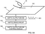
- Figure 5A illustrates an embodiment of the haptic output device 130 configured to generate a haptic effect at a surface 112 of the hidden control 110.
- the haptic effect may be generated to simulate a feature, such as a surface feature, represented by the hidden control 110.
- the simulated surface feature may be a simulated texture, spatial pattern, edge or border, or any other tactile sensation, whether natural or artificial, at surface 112.
- the spatial pattern may include a grid of straight lines, a grid of concentric circles, a grid of points, a grid of tiles, any combination thereof, or any other spatial pattern.
- the haptic output device 130 may be operatively coupled to a haptic drive circuit 132 configured to apply a drive signal to the haptic output device 130.
- the haptic drive circuit 132 may comprise an amplifier configured to amplify or buffer a signal from the haptic output device control module 158.
- the haptic drive circuit 132 may be omitted, and the haptic output device control module 158 may output a signal directly to the haptic output device 130.
- the haptic output device control module 156 and the haptic output device 130 may be configured to simulate surface features at the surface 112 by controlling a level of friction.
- the haptic output device 130 including an actuator may control the level of friction by generating vibrations at the surface 112.
- the haptic output device 130 including an electrostatic device may control a level of friction through applying a voltage to or underneath the surface 112.
- An alternating voltage signal for example, may create a capacitive effect that attracts the user's finger 10, a stylus, or any other object at the surface 112.
- the attractive force at the surface may be perceived as friction as the object moves across the surface. Increasing the attractive force may increase a level of friction at the surface.
- an electrostatic device may, in an embodiment, be used with a surface that includes a conductive layer having one or more electrodes and that includes an insulating layer.
- the conducting layer may be any semiconductor or other conductive material.
- the insulating layer may be glass, plastic (e.g., thermoplastic), polymer, or any other insulating layer.
- the electrostatic device may operate by applying an AC signal that, in an embodiment, capacitively couples the conducting layer with an object near or touching the surface 112.
- the AC signal may be generated by a high-voltage amplifier located in the haptic drive circuit 132.
- the capacitive coupling may control a level of friction on the surface 112.
- a surface feature may be simulated by controlling the level of friction on the surface 112. Varying the levels of attraction between the object and the conducting layer can vary the friction on an object moving across the surface 112. A region having a different level of friction than surrounding regions may represent a spatial pattern component, a texture, or any other surface feature.
- the capacitive coupling may also generate a haptic effect by stimulating parts of the object near or touching the surface 112, such as mechanoreceptors in the skin of a user's finger(s).
- the conducting layer may be applied with an AC voltage signal that couples with conductive parts of a user's finger.
- the user may sense a texture of prickliness, graininess, bumpiness, roughness, stickiness, or some other texture.
- the surface 112 may not have an insulating layer, so that an object can directly touch the conducting layer.
- a haptic effect may be generated by applying a voltage from the conducting layer to the object through an electrically conductive path. Simulating a texture through a periodic or other haptic effect is discussed in more detail in U.S. Patent Application Serial No. 13/665,526 , titled “Method and Apparatus for Simulating Surface Features on a User Interface with Haptic Effects," filed October 31, 2012, the entire content of which is incorporated herein by reference.
- the haptic output device control module 156 may be configured to cause the haptic output device 130 to generate a periodic haptic effect.
- Figure 5A illustrates a periodic haptic effect based on a haptic drive signal 501.
- the haptic drive signal 501 may be a periodic drive signal.
- haptic drive signals may represent haptic effects generated by haptic output devices.
- a haptic effect based on the haptic drive signal 501 may include a sinusoidal AC voltage that has a frequency and amplitude matching or proportional to the haptic drive signal 501.
- a haptic effect based on the haptic drive signal 501 may include a vibration that that has a frequency and amplitude matching the haptic drive signal 501.
- the periodic haptic effect may vary according to a sinusoidal waveform, as illustrated in Figure 5A , a square, triangular, or sawtooth waveform, or any other periodic waveform.
- a periodic electrostatic effect may be generated by an AC voltage having a sinusoidal, square, triangular, sawtooth, or any other waveform.
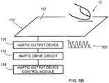
- the haptic output device control module 156 may cause the haptic output device 130 to alter the haptic effect as the user applies a gesture to the hidden control 110 to assist in guiding the user to apply the correct gesture.
- Figures 5A-5B illustrate, for example, altering a frequency of a periodic haptic effect as the user's finger 10, or any other object creating a touch input, moves across the surface 112.
- the haptic drive signal may be altered so that a haptic drive signal 503 having a greater frequency as compared to haptic drive signal 501 of Figure 5A is generated.
- Generating periodic haptic effects is discussed in more detail in U.S. Patent Application Serial No. 13/665,526 , titled “Method and Apparatus for Simulating Surface Features on a User Interface with Haptic Effects," filed October 31, 2012, the entire content of which is incorporated herein by reference.
- the hidden control 110 may be further configured to change the state of a physical or digital system.
- the system may also include a mechanism configured to convert a digital command into a physical instantiation, such as unlocking a door.
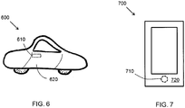
- Figure 6 illustrates a vehicle 600 that includes a hidden control 610 in place of a conventional door handle that may be used to open a door 620 of the vehicle 600.
- the vehicle 600 may be designed to have very clean lines by completely removing the door handles and replacing the door handles with touch panels that include the hidden control 610.
- Haptic feedback provided by the hidden control 610 makes it possible for the user of the vehicle 600 to find and operate the virtual door handle in a satisfying manner.
- the hidden control may be in the form of a switch for the ignition of car and may be configured to require the car operator to activate a hidden control that is invisible but may be felt by touch.
- Figure 7 illustrates an electronic device 700, which may be, for example, a smartphone or tablet that includes a hidden control 710 in accordance with embodiments as described herein.
- the hidden control 710 may be in the form of a virtual button on a front panel of the electronic device 700 instead of a physical button, which may give the electronic device 700 a clean look, without moving parts.
- the hidden control 710, i.e. virtual button in this embodiment, is not visible but may be felt by the user through haptic feedback, as described above, on a surface 720 of the electronic device 700.
- Figure 8 illustrates a door 800 that may include a hidden control 810 in place of a physical door knob, which may make the control for opening the door 800 more difficult to find without looking suspicious.
- a user may already know the location of the hidden control 810 and touch the location of the hidden control 810.
- haptic feedback may be generated to provide confirmation to the user that the hidden control 810 is being properly manipulated.
- the hidden control 810 actuates a mechanism in the door 800 that is configured to unlock the door 800 and allow the door 800 to be opened.
- Figure 9 illustrates a display case 900 for use in a museum or a store, for example, that includes a hidden control 910 in the form of a hidden handle known only to the staff to access the items in the display case 900.
- the display case 900 may have a more pleasant look for visitors but still be functional for staff to access the item(s) in the display case 900.
- the user may already know the location of the hidden control 910 and touch the location of the hidden control 910.
- the hidden control 910 may generate a haptic effect to assist the user to locate the hidden control 910, as described above.
- haptic feedback is generated to provide confirmation to the user that the hidden control 910 is being properly manipulated.
- the hidden control 910 actuates a mechanism in the display case 900 that is configured to unlock the display case 900 and allow the display case 900 to be opened.
- the hidden control may be in the form of a silent alarm in a bank that may be triggered by activating the hidden control that may be located with haptic feedback.
- a hidden control may be provided on the top of a desk or counter where the bank employee's hands are typically located so that the triggering of the silent alarm may be completely unnoticeable to others.
- the hidden control may be in the form of a dial of a safe, which may be hidden from sight, but found by touching the appropriate location on a surface of the safe, thereby making it difficult for a thief to find.
- Embodiments as described herein make it possible to use hidden controls with minimal compromise on usability, which may improve the aesthetics and security of certain devices and spaces.
- Embodiments as described herein may be used to increase security, because a hidden control may be difficult to locate, or its existence may even be unknown, without prior information. This may reduce the risk of an unauthorized person accessing the control without detection.
- the dial for a safe may be hidden on a featureless wall, thereby making it difficult to locate by a thief.
- Embodiments as described herein may provide a hidden control for a space that only needs to be accessed by a few people and is completely hidden from view for all others. For example, a supply closet in a public space may be hidden from all but the persons needing to access the supply closet, thereby making the space more pleasant for visitors.
Description
- The present invention is related to usable hidden controls with haptic feedback.
- Hidden controls have been used to provide a user control over an action without the knowledge of others. For example, banks use hidden controls to allow employees to initiate silent alarms when threatened. Such hidden controls are typically in the form of a mechanical button that is hidden from view from the public, for example beneath a counter or desk, yet easily located by the employee by feeling the button without having to look at the button.
- It is desirable to be able to use hidden controls that are in locations within plain sight of the public, but are still hidden from view. Such hidden controls may allow designers to create aesthetically pleasing minimalist designs with clean lines and surfaces, without compromising usability.
-
US 2007/236450 discloses a haptic device operable to provide indirect haptic feedback and virtual texture sensations to a user by modulation of friction of a touch surface of the device in response to one or more parameters. In particular,US 2007/236450 discloses the following features: A system configured to activate a hidden control, the system comprising: a sensor configured to sense an input by a user, the input comprising a gesture; a haptic output device configured to output a haptic effect as the input is being sensed; and a processor configured to determine if the sensed input corresponds to a predetermined gesture associated with activation of a control, and if the sensed input corresponds to the predetermined gesture to activate the control.US 2007/126561 discloses a vehicle with integrated keyless entry system and component monitoring capabilities. A processor unlocks or locks the door based on signals generated or modified by a portable identification device and received by an interrogator.DE 20 2012 005255 discloses a control device for a vehicle or household appliance comprising a gesture monitoring unit enabling a non-tactile gesture of a user to be detected. - Aspects of the present invention make it possible to use hidden controls while maintaining a level of usability. The availability of usable hidden controls could make them more appealing for a wide range of applications and devices.
- The present invention is as set out in the appended claims.
- According to a first aspect of the invention, there is provided a system configured to activate a hidden control, the system comprising a sensor configured to sense an input by a user, the input comprising a gesture, a haptic output device configured to output a haptic feedback as the input is being sensed, a user identification device configured to determine the user's identity; and a processor configured to determine whether the identified user has permission to activate the control and to determine if the sensed input corresponds to a predetermined gesture associated with activation of a control, and if the user is determined to have permission and the sensed input corresponds to the predetermined gesture to activate the control, wherein the haptic output device is configured to generate a second haptic effect if the user is determined to have permission to activate the control, and wherein the second haptic effect is generated to identify the location of the touch surface for the user to apply the gesture.
- The first aspect may be modified in any suitable way as disclosed herein including but not limited to any one or more of the following.
- The system may be configured such that the control is a lock and activation of the control comprises unlocking the lock.
- The system may be configured such that the haptic output device includes an actuator.
- The system may be configured such that the haptic output device includes a non-mechanical or non-vibratory device.
- The system may be configured such that the haptic output device comprises an actuator or a non-mechanical or non-vibratory device.
- The system may be configured such that the haptic output device is configured to generate electrostatic friction or ultrasonic surface friction.
- The system may be configured such that the user identification device is configured to sense a radio frequency identification tag.
- The system may be configured such that the user identification device includes a biometric sensor.
- The system may be configured such that the second haptic effect includes electrostatic friction or ultrasonic surface friction.
- According to a second aspect of the invention, there is provided a method for activating a hidden control, the method comprising sensing a gesture applied to a touch surface by a user, generating haptic feedback to the user as the gesture is being sensed, determining the user's identity, determining whether the identified user has permission to activate the control; determining whether the sensed gesture corresponds to a predetermined gesture associated with activation of a control, and activating the control if the user is determined to have permission and the sensed gesture is determined to correspond to the predetermined gesture associated with activation of the control, and generating a second haptic feedback if the user is determined to have permission to activate the control, wherein the second haptic effect is generated to identify the location of the touch surface for the user to apply the gesture .
- The second aspect may be modified in any suitable way as disclosed herein including but not limited to any one or more of the following.
- The method may be configured such that the control is a lock and said activating the control comprises unlocking the lock.
- The method may be configured such that the haptic feedback is generated with a haptic output device.
- The method may be configured such that the haptic feedback includes a vibration.
- The method may be configured such that the haptic feedback includes electrostatic friction or ultrasonic surface friction.
- The method may be configured such that the haptic feedback comprises a vibration, electrostatic friction or ultrasonic friction.
- The method may be configured such that the user's identity is determined by detecting a radio frequency identification tag within a vicinity of the hidden control.
- The method may be configured such that the user's identify is determined with a biometric sensor.
- The method may be configured such that the second haptic feedback includes electrostatic friction or ultrasonic surface friction.
- These and other aspects, features, and characteristics of the present invention, as well as the methods of operation and functions of the related elements of structure and the combination of parts and economies of manufacture, will become more apparent upon consideration of the following description and the appended claims with reference to the accompanying drawings, all of which form a part of this specification. It is to be expressly understood, however, that the drawings are for the purpose of illustration and description only and are not intended as a definition of the limits of the invention. As used in the specification and in the claims, the singular form of "a", "an", and "the" include plural referents unless the context clearly dictates otherwise.
- The components of the following Figures are illustrated to emphasize the general principles of the present disclosure and are not necessarily drawn to scale. Reference characters designating corresponding components are repeated as necessary throughout the Figures for the sake of consistency and clarity.
- Embodiments of the present invention will now be described in detail with reference to the accompanying drawings, in which:
-
Figure 1 schematically illustrates a system for providing and activating a hidden control in accordance with embodiments as described herein; -
Figure 2 schematically illustrates a processor of the system ofFigure 1 ; -
Figure 3 schematically illustrates a method for sensing a gesture for operating the hidden control ofFigure 1 ; -
Figure 4 schematically illustrates a method for identifying an authorized user of the system ofFigure 1 ; -
Figures 5A and5B schematically illustrate a portion of the system ofFigure 1 , in accordance with embodiments as described herein; -
Figure 6 schematically illustrates an implementation of the system ofFigure 1 , in accordance with an embodiment as described herein; -
Figure 7 schematically illustrates an implementation of the system ofFigure 1 , in accordance with an embodiment as described herein; -
Figure 8 schematically illustrates an implementation of the system ofFigure 1 , in accordance with an embodiment as described herein; and -
Figure 9 schematically illustrates an implementation of the system ofFigure 1 , in accordance with an embodiment as described herein. -
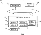
Figure 1 is a schematic illustration of asystem 100 in accordance with embodiments as described herein. As illustrated, thesystem 100 includes an input/output device 110, which is in the form of a hidden control that is configured to be invisible or substantially invisible to the human eye. Thehidden control 110 may be a physical or virtual control, such as a button, a latch, and/or a lock, as described in further detail below. Thehidden control 110 includes asensor 120 configured to sense an input of a user, ahaptic output device 130 configured to output a haptic feedback to the user, and may optionally include adisplay 140, an audio output device, such as aspeaker 142, and auser identification device 180. - The
sensor 120 may be a touch sensor configured to detect gestures or manipulations of the hidden control, such as tapping, sliding, rubbing, or pressing a surface of thehidden control 110, or dragging an object, such as a finger or stylus, against the surface of thehidden control 110. The touch sensor may also be configured to support the rendering of haptic effects, such as the modulation of friction effects as a finger slides against a hidden control, as discussed in further detail below with respect to thehaptic output device 130, which may be integrated with thesensor 120 or separate from thesensor 120. Several technologies may be used for this purpose, such as capacitive or resistive sensing, force-sensitive resistors, or optical switches, for example. - The
haptic output device 130 is configured to provide haptic feedback to at least a portion of thehidden control 110, which can be conveyed to a user in contact with thehidden control 110. The haptic feedback generated by thehaptic output device 130 may take several forms. For example, the location of thehidden control 110 may be marked with a haptic effect. A haptic effect could, for example, be triggered when entering or leaving the control, such as a friction impulse or a vibrotactile effect. A continuous or semi-continuous effect could also be played while contacting the hidden control, such as a friction texture or a continuous vibration. In an embodiment, the operation of thehidden control 110 may be augmented with haptic effects. Detents, for example, may be produced while moving a simulated dial or button. Confirmation effects may also be played when an operation is completed, such as when a latch has been released. - The haptic feedback may be created with any method of creating a haptic effect, such as vibration, deformation, kinesthetic sensations, electrostatic or ultrasonic friction, etc. The
haptic output device 130 may include one or more actuators, driving circuitry, and a haptic engine configured to generate driving signals for the actuator(s). Thehaptic output device 130 may use a variety of surface haptic technologies such as friction displays, vibrotactile actuators, and/or electrotactile arrays, etc. - For example, in an embodiment, the
haptic output device 130 may include an actuator, for example, an electromagnetic actuator such as an Eccentric Rotating Mass ("ERM") in which an eccentric mass is moved by a motor, a Linear Resonant Actuator ("LRA") in which a mass attached to a spring is driven back and forth, or a "smart material" such as piezoelectric materials, electro-active polymers or shape memory alloys, a macro-composite fiber actuator, an electro-static actuator, an electro-tactile actuator, and/or another type of actuator that provides a physical feedback such as a haptic (e.g., vibrotactile) feedback. Thehaptic output device 130 may include non-mechanical or non-vibratory devices such as those that use electrostatic friction (ESF), ultrasonic surface friction (USF), or those that induce acoustic radiation pressure with an ultrasonic haptic transducer, or those that use a haptic substrate and a flexible or deformable surface, or those that provide projected haptic output such as a puff of air using an air jet, and so on. In an embodiment, multiple haptic output devices may be used to generate different haptic effects. - In an embodiment, the
haptic output device 130 may be configured to produce haptic feedback without an electromechanical device. For example, a different material may be used for the surface of thehidden control 110 such that its texture feels different from the surfaces surrounding thehidden control 110 but the material providing the texture visually appears the same as the surrounding surface material. - The haptic feedback provided by the
haptic output device 130 may be used to mark the location of thehidden control 110. For example, a hidden virtual button may have a texture produced by a friction display that makes it easier to find on an otherwise featureless surface. Thehaptic output device 130 may provide haptic feedback to confirm that thehidden control 110 is responding to the touch provided by the user or that the function that thehidden control 110 controls has been activated. For example, a hidden virtual latch may produce a vibration cue as the latch is moved to open a door. As discussed in further detail below, these haptic effects provided by thehaptic output device 130 may be altered as a function of the state of thesystem 100. For example, location or confirmation cues may be disabled unless certain credentials, such as a radio frequency identification ("RFID") tag or badge with certain permissions, has been detected. Similarly, a hidden button that is currently unavailable to operate may be marked with a different friction texture. - The
hidden control 110 may optionally include adisplay 140 that is configured to provide a visual signal to the user. Thedisplay 140 may be configured to illuminate or glow or may be configured to display an image when the user touches thehidden control 110 to activate thehidden control 110. In an embodiment, thesensor 120 and thedisplay 140 may be combined into a touch screen. Thehidden control 110 may include an audio output device, such as aspeaker 142, that is configured to provide audio feedback when the user touches thehidden control 110 to activate thehidden control 110. - As illustrated, the
system 100 also aprocessor 150 and amemory device 160 which are interconnected to thehidden control 110 via abus 170. In an embodiment, theprocessor 150,memory device 160, andbus 170 may be part of thehidden control 110. - The
processor 150 may be a general-purpose or specific-purpose processor or microcontroller for managing or controlling the operations and functions of thesystem 100. For example, theprocessor 150 may be specifically designed as an application-specific integrated circuit ("ASIC") to control output signals to thehaptic output device 130 to provide haptic effects. Theprocessor 150 may be configured to decide, based on predefined factors, what haptic effects are to be generated based on a haptic signal received or determined by theprocessor 150, the order in which the haptic effects are generated, and the magnitude, frequency, duration, and/or other parameters of the haptic effects. Theprocessor 150 may also be configured to provide streaming commands that may be used to drive thehaptic output device 130 for providing a particular haptic effect. In some embodiments, theprocessing device 150 may include a plurality of processors, each configured to perform certain functions within thesystem 100. Theprocessor 150 may be embedded in thehidden control 110 or may be embedded in a remote computer, such as on a centralized server. Theprocessor 150 is described in further detail below. - The
memory device 160 may include one or more internally fixed storage units, removable storage units, and/or remotely accessible storage units. The various storage units may include any combination of volatile memory and non-volatile memory. The storage units may be configured to store any combination of information, data, instructions, software code, etc. More particularly, the storage units may include haptic effect profiles, instructions for how thehaptic output device 130 of thehidden control 110 is to be driven, or other information for generating haptic effects. - The
user identification device 180 may be a device that is associated with an authorized user of thehidden control 110 and may communicate with, for example, a radio frequency identification ("RFID")tag 182 that is carried by the user so that when the user approaches the hidden control, the signal output by theRFID tag 182 may be detected by theuser identification device 180 and used to determine whether or not the user carrying theRFID tag 182 is authorized to activate thehidden control 110, as discussed in further detail below. In an embodiment, theuser identification device 180 may include a biometric sensor, such as a fingerprint sensor, an iris or retinal scanner, etc., that is configured to identify the user. In an embodiment, theuser identification device 180 may include an image capturing device, such as a camera, configured to capture an image of the user's face or images that capture the user's gait, or any other image(s) that may be used to determine whether the user is authorized to activate thehidden control 110. -
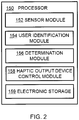
Figure 2 illustrates an embodiment of theprocessor 150 in more detail. Theprocessor 150 may be configured to execute one or more computer program modules. The one or more computer program modules may include one or more of asensor module 152, a user identification module 154, adetermination module 156, a haptic outputdevice control module 158, and/or other modules. Theprocessor 150 may also includeelectronic storage 159, which may be the same as thememory device 160 or in addition to thememory device 160. Theprocessor 150 may be configured to execute themodules processor 150. - It should be appreciated that although
modules Figure 2 as being co-located within a single processing unit, in embodiments in which theprocessor 150 includes multiple processing units, one or more ofmodules different modules modules modules modules processor 150 may be configured to execute one or more additional modules that may perform some or all of the functionality attributed below to one of themodules - The
sensor module 152 is configured to receive an input signal from thesensor 120 that is generated when thesensor 120 detects an input from a user. Thesensor module 152 is further configured to determine whether the input signal received from thesensor 120 is indicative of a user trying to operate thehidden control 110 or whether the sensed input from the user was merely an incidental touch of thehidden control 110. If thesensor module 152 determines that the input signal corresponds to a mere incidental touch and not an intentional gesture or manipulation of thehidden control 110 because the sensed input did not exceed a predetermined threshold value, thesensor module 152 may be programmed to ignore the input signal so that no further action is taken. - The user identification module 154 is configured to receive a signal from the user identification device 190 and determine whether the signal indicative of the user matches a preprogrammed user identification indicating that the user is authorized to operate the
hidden control 110, as discussed in further detail below. - The
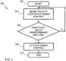
determination module 156 is configured to receive an input signal from thesensor module 152 to determine whether thehidden control 110 should be operated based on the received signals. In an embodiment, thedetermination module 156 is configured to execute amethod 300 illustrated inFigure 3 . Themethod 300 starts at 302. At 304, thesensor 120 senses a touch by a user at the location of thehidden control 110. At 306, thedetermination module 156 determines whether the touch that was sensed by thesensor 120 matches a predetermined gesture that indicates that thehidden control 110 should be actuated. The predetermined gesture may be preprogrammed into the processor and may reside in a library of preprogrammed gestures, or the user may be able to program predetermined gestures by running thedetermination module 156 in a teach mode and assign different gestures to different functions provided by theprocessor 150. - Returning to the
method 300 ofFigure 3 , if the touch that was sensed by thesensor 120 does not match the predetermined gesture, themethod 300 returns to 304. If the touch that was sensed by thesensor 120 does match the predetermined gesture, the method proceeds to 308 and thedetermination module 156 sends a signal to actuate thehidden control 110. For example, when thehidden control 110 controls a lock, the signal that is sent by thedetermination module 156 causes actuation of the lock so that the lock moves from a locked condition to an unlocked condition, or vice-versa. Themethod 300 ends at 310. In an embodiment, thesensor module 152 may be configured to execute at least a portion of themethod 300 illustrated inFigure 3 . For example, steps 302-306 may be executed by thesensor module 152 and steps 308-310 may be executed by thedetermination module 156. In an embodiment, theentire method 300 ofFigure 3 may be executed by thesensor module 152. - In an embodiment, the
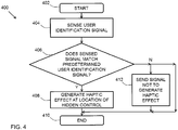
determination module 156 may be configured to receive an input signal from the user identification module 154 to determine whether thehidden control 110 should be operated based on the received signal. For example, thedetermination module 156 may be programmed with a predetermined list of authorized users and each authorized user may have a distinct signal associated therewith. In an embodiment, thedetermination module 156 is configured to execute amethod 400 illustrated inFigure 4 . Themethod 400 starts at 402. At 404, a user identification signal is sensed by theuser identification device 180 and theuser identification device 180 outputs an input user signal to thedetermination module 156. Upon receipt of the input user signal, which corresponds to a user who has approached thehidden control 110 and/or attempted to manipulate thehidden control 110, from the user identification module 154, a comparison between the input user signal and the predetermined user identification signals that that correspond to the predetermined list of authorized users may be made by thedetermination module 156 at 406. - If the input user signal matches one of the predetermined user identification signals, the
determination module 156 may provide a signal to the hapticoutput control module 158 indicating that the haptic outputdevice control module 158 should proceed with determining a haptic effect to be generated by thehaptic output device 130 at 408. If the input user signal does not match one of the predetermined user identification signals that corresponds to the predetermined list of authorized users, the method ends at 410 or thedetermination module 156 provides a signal to the hapticoutput device module 158 indicating that the haptic outputdevice control module 158 should not determine a haptic effect to be generated by thehaptic output device 130 at 412 before the method ends at 410, depending on how thedetermination module 156 is programmed. In other words, if the input user signal does not match one of the predetermined user identification signals corresponding to an authorized user, no haptic effect will be generated, and the location of thehidden control 110 may remain undetectable. - In an embodiment, the
determination module 156 may be programmed to run themethod 400 ofFigure 4 before running themethod 300 ofFigure 3 and if thedetermination module 156 determines that the user is not an authorized user, themethod 300 may not start at 302, even if the user touches the location of thehidden control 110 and provides the correct predetermined gesture. In other words, for security purposes, thehidden control 110 may remain hidden to the user by not providing haptic feedback or actuation of the control if the user is not authorized to operate thehidden control 110. This extra layer of security is considered to be optional, and thedetermination module 156 may be configured to execute themethod 300 ofFigure 3 and not themethod 400 ofFigure 4 . In an embodiment, the user identification module 154 may be configured to execute at least a portion of themethod 400 ofFigure 4 . For example, steps 402-406 may be executed by the user identification module 154 and steps 408-412 may be executed by thedetermination module 156. In an embodiment, theentire method 400 may be executed by the user identification module 154. - The haptic output
device control module 158 is configured to determine the haptic effect to be generated by thehaptic output device 130, based on a signal generated by thedetermination module 156. Determining the haptic effect may include determining one or more parameters that include an amplitude, frequency, duration, etc., of the haptic effect that will enhance one or more aspects of the experience provided by the content to the user. -
Figure 5A illustrates an embodiment of thehaptic output device 130 configured to generate a haptic effect at asurface 112 of thehidden control 110. The haptic effect may be generated to simulate a feature, such as a surface feature, represented by thehidden control 110. For example, the simulated surface feature may be a simulated texture, spatial pattern, edge or border, or any other tactile sensation, whether natural or artificial, atsurface 112. The spatial pattern may include a grid of straight lines, a grid of concentric circles, a grid of points, a grid of tiles, any combination thereof, or any other spatial pattern. - In the illustrated embodiment, the
haptic output device 130 may be operatively coupled to ahaptic drive circuit 132 configured to apply a drive signal to thehaptic output device 130. Thehaptic drive circuit 132 may comprise an amplifier configured to amplify or buffer a signal from the haptic outputdevice control module 158. In an embodiment, thehaptic drive circuit 132 may be omitted, and the haptic outputdevice control module 158 may output a signal directly to thehaptic output device 130. - In an embodiment, the haptic output
device control module 156 and thehaptic output device 130 may be configured to simulate surface features at thesurface 112 by controlling a level of friction. For example, thehaptic output device 130 including an actuator may control the level of friction by generating vibrations at thesurface 112. Thehaptic output device 130 including an electrostatic device may control a level of friction through applying a voltage to or underneath thesurface 112. An alternating voltage signal, for example, may create a capacitive effect that attracts the user'sfinger 10, a stylus, or any other object at thesurface 112. The attractive force at the surface may be perceived as friction as the object moves across the surface. Increasing the attractive force may increase a level of friction at the surface. - Controlling friction through a haptic effect is discussed in more detail in
U.S. Patent Application Serial No. 13/092,269 2012/0268412 , the entire content of which is incorporated herein by reference. As described in that application, an electrostatic device may, in an embodiment, be used with a surface that includes a conductive layer having one or more electrodes and that includes an insulating layer. The conducting layer may be any semiconductor or other conductive material. The insulating layer may be glass, plastic (e.g., thermoplastic), polymer, or any other insulating layer. The electrostatic device may operate by applying an AC signal that, in an embodiment, capacitively couples the conducting layer with an object near or touching thesurface 112. The AC signal may be generated by a high-voltage amplifier located in thehaptic drive circuit 132. - The capacitive coupling may control a level of friction on the
surface 112. In an embodiment, a surface feature may be simulated by controlling the level of friction on thesurface 112. Varying the levels of attraction between the object and the conducting layer can vary the friction on an object moving across thesurface 112. A region having a different level of friction than surrounding regions may represent a spatial pattern component, a texture, or any other surface feature. The capacitive coupling may also generate a haptic effect by stimulating parts of the object near or touching thesurface 112, such as mechanoreceptors in the skin of a user's finger(s). In an embodiment, the conducting layer may be applied with an AC voltage signal that couples with conductive parts of a user's finger. As the user moves his or her finger on thesurface 112 at the location of thehidden control 110, the user may sense a texture of prickliness, graininess, bumpiness, roughness, stickiness, or some other texture. In an embodiment, thesurface 112 may not have an insulating layer, so that an object can directly touch the conducting layer. A haptic effect may be generated by applying a voltage from the conducting layer to the object through an electrically conductive path. Simulating a texture through a periodic or other haptic effect is discussed in more detail inU.S. Patent Application Serial No. 13/665,526 - In an embodiment, the haptic output
device control module 156 may be configured to cause thehaptic output device 130 to generate a periodic haptic effect.Figure 5A , for example, illustrates a periodic haptic effect based on ahaptic drive signal 501. In some instances, thehaptic drive signal 501 may be a periodic drive signal. In some instances, haptic drive signals may represent haptic effects generated by haptic output devices. For example, if thehaptic output device 130 includes an electrostatic device, a haptic effect based on thehaptic drive signal 501 may include a sinusoidal AC voltage that has a frequency and amplitude matching or proportional to thehaptic drive signal 501. If thehaptic output device 130 includes an actuator, a haptic effect based on thehaptic drive signal 501 may include a vibration that that has a frequency and amplitude matching thehaptic drive signal 501. The periodic haptic effect may vary according to a sinusoidal waveform, as illustrated inFigure 5A , a square, triangular, or sawtooth waveform, or any other periodic waveform. For example, a periodic electrostatic effect may be generated by an AC voltage having a sinusoidal, square, triangular, sawtooth, or any other waveform. - In an embodiment, the haptic output
device control module 156 may cause thehaptic output device 130 to alter the haptic effect as the user applies a gesture to thehidden control 110 to assist in guiding the user to apply the correct gesture.Figures 5A-5B illustrate, for example, altering a frequency of a periodic haptic effect as the user'sfinger 10, or any other object creating a touch input, moves across thesurface 112. For example, as illustrated inFigure 5B , the haptic drive signal may be altered so that ahaptic drive signal 503 having a greater frequency as compared tohaptic drive signal 501 ofFigure 5A is generated. Generating periodic haptic effects is discussed in more detail inU.S. Patent Application Serial No. 13/665,526 - The
hidden control 110 may be further configured to change the state of a physical or digital system. For example, the system may also include a mechanism configured to convert a digital command into a physical instantiation, such as unlocking a door. -
Figure 6 illustrates avehicle 600 that includes ahidden control 610 in place of a conventional door handle that may be used to open adoor 620 of thevehicle 600. By replacing the conventional door handle with a hidden control in accordance with embodiments as described herein, thevehicle 600 may be designed to have very clean lines by completely removing the door handles and replacing the door handles with touch panels that include thehidden control 610. Haptic feedback provided by thehidden control 610 makes it possible for the user of thevehicle 600 to find and operate the virtual door handle in a satisfying manner. In an embodiment, the hidden control may be in the form of a switch for the ignition of car and may be configured to require the car operator to activate a hidden control that is invisible but may be felt by touch. -
Figure 7 illustrates anelectronic device 700, which may be, for example, a smartphone or tablet that includes ahidden control 710 in accordance with embodiments as described herein. In an embodiment, thehidden control 710 may be in the form of a virtual button on a front panel of theelectronic device 700 instead of a physical button, which may give the electronic device 700 a clean look, without moving parts. Thehidden control 710, i.e. virtual button in this embodiment, is not visible but may be felt by the user through haptic feedback, as described above, on asurface 720 of theelectronic device 700. -
Figure 8 illustrates adoor 800 that may include ahidden control 810 in place of a physical door knob, which may make the control for opening thedoor 800 more difficult to find without looking suspicious. When a user approaches thedoor 800 to open the door, the user may already know the location of thehidden control 810 and touch the location of thehidden control 810. As the user applies a gesture to thehidden control 810, such as drawing a circle to simulate turning a doorknob, haptic feedback may be generated to provide confirmation to the user that thehidden control 810 is being properly manipulated. Upon completion of the predetermined gesture, thehidden control 810 actuates a mechanism in thedoor 800 that is configured to unlock thedoor 800 and allow thedoor 800 to be opened. -
Figure 9 illustrates adisplay case 900 for use in a museum or a store, for example, that includes ahidden control 910 in the form of a hidden handle known only to the staff to access the items in thedisplay case 900. Thedisplay case 900 may have a more pleasant look for visitors but still be functional for staff to access the item(s) in thedisplay case 900. When a user approaches thedisplay case 900 to open the display case, the user may already know the location of thehidden control 910 and touch the location of thehidden control 910. In an embodiment, even if the user does not know the precise location of thehidden control 910, if the user is an authorized user, thehidden control 910 may generate a haptic effect to assist the user to locate thehidden control 910, as described above. As the user applies a gesture to thehidden control 910, haptic feedback is generated to provide confirmation to the user that thehidden control 910 is being properly manipulated. Upon completion of the predetermined gesture, thehidden control 910 actuates a mechanism in thedisplay case 900 that is configured to unlock thedisplay case 900 and allow thedisplay case 900 to be opened. - In an embodiment, the hidden control may be in the form of a silent alarm in a bank that may be triggered by activating the hidden control that may be located with haptic feedback. Such a hidden control may be provided on the top of a desk or counter where the bank employee's hands are typically located so that the triggering of the silent alarm may be completely unnoticeable to others.
- In an embodiment, the hidden control may be in the form of a dial of a safe, which may be hidden from sight, but found by touching the appropriate location on a surface of the safe, thereby making it difficult for a thief to find.
- Embodiments as described herein make it possible to use hidden controls with minimal compromise on usability, which may improve the aesthetics and security of certain devices and spaces. Embodiments as described herein may be used to increase security, because a hidden control may be difficult to locate, or its existence may even be unknown, without prior information. This may reduce the risk of an unauthorized person accessing the control without detection. For example, the dial for a safe may be hidden on a featureless wall, thereby making it difficult to locate by a thief.
- Embodiments as described herein may provide a hidden control for a space that only needs to be accessed by a few people and is completely hidden from view for all others. For example, a supply closet in a public space may be hidden from all but the persons needing to access the supply closet, thereby making the space more pleasant for visitors.
- The embodiments described herein represent a number of possible implementations and examples and are not intended to necessarily limit the present disclosure to any specific embodiments. Instead, various modifications can be made to these embodiments as would be understood by one of ordinary skill in the art. Any such modifications are intended to be included within the scope of the present disclosure and protected by the following claims.
- Embodiments of the present invention have been described with particular reference to the examples illustrated. However, it will be appreciated that variations and modifications may be made to the examples described within the scope of the present invention.
Claims (12)
- A system (100) configured to activate a hidden control (110; 610; 710; 810; 910), the system (100) comprising:a sensor (120) configured to sense an input by a user, the input comprising a gesture;a haptic output device (130) configured to output a haptic effect as the input is being sensed; anda user identification device (180) configured to determine the user's identity; anda processor (150) configured to determine whether the identified user has permission to activate the control (110; 610; 710; 810; 910) and to determine if the sensed input corresponds to a predetermined gesture associated with activation of a control (110; 610; 710; 810; 910), and if the user is determined to have permission and the sensed input corresponds to the predetermined gesture to activate the control (110; 610; 710; 810; 910),wherein the haptic output device (130) is configured to generate a second haptic effect if the user is determined to have permission to activate the control (110; 610; 710; 810; 910), and wherein the second haptic effect is generated to identify the location of the touch surface (112) for the user to apply the gesture.
- The system of claim 1, wherein the control is a lock and activation of the control comprises unlocking the lock.
- The system of claims 1 or 2, wherein the haptic output device comprises an actuator or a non-mechanical or non-vibratory device.
- The system of any of claims 1 - 3, wherein the haptic output device is configured to generate electrostatic friction or ultrasonic surface friction.
- The system of claim 1, wherein the user identification device is configured to sense a radio frequency identification tag.
- The system of claims 1, wherein the user identification device comprises a biometric sensor.
- A method for activating a hidden control (110;610; 710; 810; 910), the method comprising:sensing a gesture applied to a touch surface (112) by a user;generating haptic feedback to the user as the gesture is being sensed;determining the user's identity;determining whether the identified user has permission to activate the control (110; 610; 710; 810; 910);determining whether the sensed gesture corresponds to a predetermined gesture associated with activation of a control (110; 610; 710; 810; 910);activating the control (110; 610; 710; 810; 910) if the user is determined to have permission and the sensed gesture is determined to correspond to the predetermined gesture associated with activation of the control (110; 610; 710; 810; 910); andgenerating a second haptic feedback if the user is determined to have permission to activate the control (110; 610; 710; 810; 910), wherein the second haptic effect is generated to identify the location of the touch surface (112) for the user to apply the gesture.
- The method of claim 7, wherein the control is a lock and said activating the control comprises unlocking the lock.
- The method of claims 7 or 8, wherein the haptic feedback is generated with a haptic output device.
- The method of any of claims 7 - 9, wherein the haptic feedback comprises a vibration, electrostatic friction or ultrasonic friction.
- The method of claim 7, wherein the user's identity is determined by detecting a radio frequency identification tag within a vicinity of the hidden control.
- The method of claim 7, wherein the user's identity is determined with a biometric sensor.
Applications Claiming Priority (1)
| Application Number | Priority Date | Filing Date | Title |
|---|---|---|---|
| US13/945,498 US10359857B2 (en) | 2013-07-18 | 2013-07-18 | Usable hidden controls with haptic feedback |
Publications (3)
| Publication Number | Publication Date |
|---|---|
| EP2827225A2 EP2827225A2 (en) | 2015-01-21 |
| EP2827225A3 EP2827225A3 (en) | 2015-04-08 |
| EP2827225B1 true EP2827225B1 (en) | 2017-04-26 |
Family
ID=51357711
Family Applications (1)
| Application Number | Title | Priority Date | Filing Date |
|---|---|---|---|
| EP14177469.5A Not-in-force EP2827225B1 (en) | 2013-07-18 | 2014-07-17 | System and method for activating a hidden control |
Country Status (5)
| Country | Link |
|---|---|
| US (1) | US10359857B2 (en) |
| EP (1) | EP2827225B1 (en) |
| JP (2) | JP6400958B2 (en) |
| KR (1) | KR20150010608A (en) |
| CN (2) | CN109613981A (en) |
Families Citing this family (52)
| Publication number | Priority date | Publication date | Assignee | Title |
|---|---|---|---|---|
| US20170371492A1 (en) * | 2013-03-14 | 2017-12-28 | Rich IP Technology Inc. | Software-defined sensing system capable of responding to cpu commands |
| US11802422B2 (en) | 2013-03-15 | 2023-10-31 | August Home, Inc. | Video recording triggered by a smart lock device |
| US9695616B2 (en) * | 2013-03-15 | 2017-07-04 | August Home, Inc. | Intelligent door lock system and vibration/tapping sensing device to lock or unlock a door |
| US11072945B2 (en) | 2013-03-15 | 2021-07-27 | August Home, Inc. | Video recording triggered by a smart lock device |
| US10388094B2 (en) | 2013-03-15 | 2019-08-20 | August Home Inc. | Intelligent door lock system with notification to user regarding battery status |
| US11527121B2 (en) | 2013-03-15 | 2022-12-13 | August Home, Inc. | Door lock system with contact sensor |
| US10181232B2 (en) | 2013-03-15 | 2019-01-15 | August Home, Inc. | Wireless access control system and methods for intelligent door lock system |
| US10443266B2 (en) | 2013-03-15 | 2019-10-15 | August Home, Inc. | Intelligent door lock system with manual operation and push notification |
| US11352812B2 (en) | 2013-03-15 | 2022-06-07 | August Home, Inc. | Door lock system coupled to an image capture device |
| US10140828B2 (en) | 2015-06-04 | 2018-11-27 | August Home, Inc. | Intelligent door lock system with camera and motion detector |
| US9704314B2 (en) | 2014-08-13 | 2017-07-11 | August Home, Inc. | BLE/WiFi bridge that detects signal strength of Bluetooth LE devices at an exterior of a dwelling |
| US11441332B2 (en) | 2013-03-15 | 2022-09-13 | August Home, Inc. | Mesh of cameras communicating with each other to follow a delivery agent within a dwelling |
| US9644398B1 (en) | 2013-03-15 | 2017-05-09 | August Home, Inc. | Intelligent door lock system with a haptic device |
| US11043055B2 (en) | 2013-03-15 | 2021-06-22 | August Home, Inc. | Door lock system with contact sensor |
| US9916746B2 (en) | 2013-03-15 | 2018-03-13 | August Home, Inc. | Security system coupled to a door lock system |
| US10691953B2 (en) | 2013-03-15 | 2020-06-23 | August Home, Inc. | Door lock system with one or more virtual fences |
| US11421445B2 (en) | 2013-03-15 | 2022-08-23 | August Home, Inc. | Smart lock device with near field communication |
| CN115700434A (en) | 2014-09-02 | 2023-02-07 | 苹果公司 | Semantic framework for variable haptic output |
| GB2530036A (en) | 2014-09-09 | 2016-03-16 | Ultrahaptics Ltd | Method and apparatus for modulating haptic feedback |
| WO2016038677A1 (en) * | 2014-09-09 | 2016-03-17 | 三菱電機株式会社 | Tactile sensation control system and tactile sensation control method |
| US10185402B2 (en) * | 2014-11-27 | 2019-01-22 | Erghis Technologies Ab | Method and system for gesture based control device |
| EP3259654B1 (en) | 2015-02-20 | 2021-12-29 | Ultrahaptics Ip Ltd | Algorithm improvements in a haptic system |
| US20190012888A1 (en) * | 2015-07-22 | 2019-01-10 | Fort Jameson, Llc | Container With Concealed Sensors |
| CN105224928B (en) * | 2015-10-09 | 2017-11-17 | 广东欧珀移动通信有限公司 | Fingerprint recognition sensing device further, electronic equipment and mobile device |
| CN105882603A (en) * | 2015-10-30 | 2016-08-24 | 乐卡汽车智能科技(北京)有限公司 | Information processing method and system |
| US9895607B2 (en) * | 2015-12-15 | 2018-02-20 | Igt Canada Solutions Ulc | Haptic feedback on a gaming terminal display |
| CN106020650B (en) * | 2016-06-06 | 2018-12-21 | 腾讯科技(深圳)有限公司 | control signal processing method, device and system |
| DK179657B1 (en) | 2016-06-12 | 2019-03-13 | Apple Inc. | Devices, methods and graphical user interfaces for providing haptic feedback |
| DK179823B1 (en) | 2016-06-12 | 2019-07-12 | Apple Inc. | Devices, methods, and graphical user interfaces for providing haptic feedback |
| EP3488427B1 (en) * | 2016-07-22 | 2023-04-05 | Harman International Industries, Incorporated | Haptic guidance system |
| US9891711B1 (en) | 2016-07-26 | 2018-02-13 | Toyota Motor Engineering & Manufacturing North America, Inc. | Human machine interface with haptic response based on phased array LIDAR |
| DK179278B1 (en) | 2016-09-06 | 2018-03-26 | Apple Inc | Devices, methods and graphical user interfaces for haptic mixing |
| DK201670720A1 (en) | 2016-09-06 | 2018-03-26 | Apple Inc | Devices, Methods, and Graphical User Interfaces for Generating Tactile Outputs |
| US10133543B2 (en) * | 2016-09-23 | 2018-11-20 | Apple Inc. | Devices, methods, and graphical user interfaces for media playback control using intensity-based user inputs |
| US20180138831A1 (en) * | 2016-11-17 | 2018-05-17 | Immersion Corporation | Control of Contact Conditions For Static ESF |
| US10921894B2 (en) * | 2017-04-10 | 2021-02-16 | Mitsubishi Electric Corporation | User interface device |
| DK201770372A1 (en) | 2017-05-16 | 2019-01-08 | Apple Inc. | Tactile feedback for locked device user interfaces |
| US11531395B2 (en) | 2017-11-26 | 2022-12-20 | Ultrahaptics Ip Ltd | Haptic effects from focused acoustic fields |
| AU2018383754A1 (en) * | 2017-12-12 | 2020-05-14 | Level Home, Inc. | Door lock bezel with touch and wireless capabilities |
| KR102077669B1 (en) * | 2018-03-06 | 2020-02-14 | 네이버랩스 주식회사 | Method and apparatus for processing sensing data associated with touch interaction of user |
| CA3098642C (en) | 2018-05-02 | 2022-04-19 | Ultrahaptics Ip Ltd | Blocking plate structure for improved acoustic transmission efficiency |
| US10632394B2 (en) * | 2018-06-27 | 2020-04-28 | Nobody Knows Llc | Timepiece illusion device |
| CN109582132B (en) * | 2018-11-01 | 2024-03-22 | 深圳岱仕科技有限公司 | Hand machinery exoskeleton and feedback control method thereof |
| US10929698B2 (en) | 2018-12-17 | 2021-02-23 | Gentex Corporation | Advanced features for vehicle authentication system |
| US11397497B2 (en) * | 2019-04-04 | 2022-07-26 | Knowles Electonics, Llc | System and method for detecting tactile interaction based on surface variations of a tactile interface |
| US11842517B2 (en) | 2019-04-12 | 2023-12-12 | Ultrahaptics Ip Ltd | Using iterative 3D-model fitting for domain adaptation of a hand-pose-estimation neural network |
| US11024134B2 (en) | 2019-09-16 | 2021-06-01 | Aurora Flight Sciences Corporation, a subsidiary of The Boeing Company | Systems and methods to allow operators to sense distance and/or direction using haptic feedback |
| US11486173B2 (en) | 2019-09-23 | 2022-11-01 | Toyota Motor Engineering & Manufacturing North America, Inc. | Fluidic elastomer actuator-based mechanical control systems for vehicle door handles |
| US11816267B2 (en) | 2020-06-23 | 2023-11-14 | Ultraleap Limited | Features of airborne ultrasonic fields |
| US11886639B2 (en) | 2020-09-17 | 2024-01-30 | Ultraleap Limited | Ultrahapticons |
| US11959308B2 (en) | 2020-09-17 | 2024-04-16 | ASSA ABLOY Residential Group, Inc. | Magnetic sensor for lock position |
| US20230418449A1 (en) * | 2022-06-22 | 2023-12-28 | Rivian Ip Holdings, Llc | User interface adjustment based on proximity to upcoming maneuver |
Citations (1)
| Publication number | Priority date | Publication date | Assignee | Title |
|---|---|---|---|---|
| US6134339A (en) * | 1998-09-17 | 2000-10-17 | Eastman Kodak Company | Method and apparatus for determining the position of eyes and for correcting eye-defects in a captured frame |
Family Cites Families (33)
| Publication number | Priority date | Publication date | Assignee | Title |
|---|---|---|---|---|
| US20070126561A1 (en) | 2000-09-08 | 2007-06-07 | Automotive Technologies International, Inc. | Integrated Keyless Entry System and Vehicle Component Monitoring |
| US6822635B2 (en) * | 2000-01-19 | 2004-11-23 | Immersion Corporation | Haptic interface for laptop computers and other portable devices |
| JP4570220B2 (en) | 2000-08-31 | 2010-10-27 | 富士通テン株式会社 | Security system |
| US20020109677A1 (en) * | 2000-12-21 | 2002-08-15 | David Taylor | Touchpad code entry system |
| JP2005307692A (en) * | 2004-04-26 | 2005-11-04 | Denso Corp | Automatic opening and closing system for power back door for vehicle |
| JP2006302199A (en) * | 2005-04-25 | 2006-11-02 | Hitachi Ltd | Information processor which partially locks window and program for operating this information processor |
| WO2007111909A2 (en) | 2006-03-24 | 2007-10-04 | Northwestern University | Haptic device with indirect haptic feedback |
| US20080006833A1 (en) * | 2006-06-02 | 2008-01-10 | Semiconductor Energy Laboratory Co., Ltd. | Lighting device and liquid crystal display device |
| US20080068334A1 (en) * | 2006-09-14 | 2008-03-20 | Immersion Corporation | Localized Haptic Feedback |
| US8866698B2 (en) * | 2008-10-01 | 2014-10-21 | Pleiades Publishing Ltd. | Multi-display handheld device and supporting system |
| US8436816B2 (en) * | 2008-10-24 | 2013-05-07 | Apple Inc. | Disappearing button or slider |
| JP2010211509A (en) * | 2009-03-10 | 2010-09-24 | Ricoh Co Ltd | Input device and image forming device |
| BRPI1011373A8 (en) * | 2009-05-09 | 2017-11-07 | Vital Art And Science Incorporated | MONITORING, VISION EVALUATION AND FORM DISCRIMINATION SYSTEM |
| JP5332956B2 (en) * | 2009-06-29 | 2013-11-06 | 日本電気株式会社 | Information processing apparatus, item display control method, item use control method, and program |
| US8390594B2 (en) * | 2009-08-18 | 2013-03-05 | Immersion Corporation | Haptic feedback using composite piezoelectric actuator |
| JP5461105B2 (en) * | 2009-08-21 | 2014-04-02 | 京セラ株式会社 | Input device |
| JP5630172B2 (en) * | 2010-09-14 | 2014-11-26 | 株式会社リコー | Input device using touch panel |
| JP5862271B2 (en) * | 2010-12-29 | 2016-02-16 | 株式会社リコー | User interface device, image forming apparatus, user interface control method and program |
| WO2012099850A2 (en) * | 2011-01-18 | 2012-07-26 | Bayer Materialscience Ag | Flexure apparatus, system, and method |
| US9448713B2 (en) | 2011-04-22 | 2016-09-20 | Immersion Corporation | Electro-vibrotactile display |
| US9733746B2 (en) * | 2011-05-10 | 2017-08-15 | Northwestern University | Touch interface device having an electrostatic multitouch surface and method for controlling the device |
| EP2715499B1 (en) * | 2011-05-23 | 2020-09-02 | Microsoft Technology Licensing, LLC | Invisible control |
| JP5869316B2 (en) * | 2011-11-25 | 2016-02-24 | 京セラ株式会社 | Portable electronic devices |
| KR101880240B1 (en) * | 2011-12-28 | 2018-07-23 | 브리티쉬 텔리커뮤니케이션즈 파블릭 리미티드 캄퍼니 | Mobile terminal and method for controlling operation thereof |
| US20130181953A1 (en) * | 2012-01-13 | 2013-07-18 | Microsoft Corporation | Stylus computing environment |
| US8854433B1 (en) * | 2012-02-03 | 2014-10-07 | Aquifi, Inc. | Method and system enabling natural user interface gestures with an electronic system |
| DE202012005255U1 (en) | 2012-05-29 | 2012-06-26 | Youse Gmbh | Operating device with a gesture monitoring unit |
| US20140009599A1 (en) * | 2012-07-03 | 2014-01-09 | Applied Nanostructure Solutions, Llc. | Methods and systems for monitoring the growth of carbon nanostructures on a substrate |
| KR20140042280A (en) * | 2012-09-28 | 2014-04-07 | 엘지전자 주식회사 | Portable device and controlling method thereof |
| US20140160029A1 (en) * | 2012-12-06 | 2014-06-12 | Jenny Yuen | Systems and Methods for a Trackpad Within a Keyboard |
| US9041647B2 (en) * | 2013-03-15 | 2015-05-26 | Immersion Corporation | User interface device provided with surface haptic sensations |
| US9303871B2 (en) * | 2013-06-26 | 2016-04-05 | Siemens Aktiengesellschaft | Combustor assembly including a transition inlet cone in a gas turbine engine |
| US8982391B2 (en) * | 2013-06-28 | 2015-03-17 | Xerox Corporation | Method and system for print driver based information exchange |
-
2013
- 2013-07-18 US US13/945,498 patent/US10359857B2/en not_active Expired - Fee Related
-
2014
- 2014-07-01 JP JP2014135873A patent/JP6400958B2/en not_active Expired - Fee Related
- 2014-07-15 KR KR20140088898A patent/KR20150010608A/en not_active Application Discontinuation
- 2014-07-17 EP EP14177469.5A patent/EP2827225B1/en not_active Not-in-force
- 2014-07-18 CN CN201811502387.5A patent/CN109613981A/en active Pending
- 2014-07-18 CN CN201410404626.9A patent/CN104298346B/en not_active Expired - Fee Related
-
2018
- 2018-09-06 JP JP2018166636A patent/JP2019008821A/en not_active Ceased
Patent Citations (1)
| Publication number | Priority date | Publication date | Assignee | Title |
|---|---|---|---|---|
| US6134339A (en) * | 1998-09-17 | 2000-10-17 | Eastman Kodak Company | Method and apparatus for determining the position of eyes and for correcting eye-defects in a captured frame |
Also Published As
| Publication number | Publication date |
|---|---|
| JP2019008821A (en) | 2019-01-17 |
| EP2827225A3 (en) | 2015-04-08 |
| US10359857B2 (en) | 2019-07-23 |
| CN104298346B (en) | 2019-01-01 |
| JP2015028777A (en) | 2015-02-12 |
| KR20150010608A (en) | 2015-01-28 |
| CN109613981A (en) | 2019-04-12 |
| CN104298346A (en) | 2015-01-21 |
| US20150022466A1 (en) | 2015-01-22 |
| JP6400958B2 (en) | 2018-10-03 |
| EP2827225A2 (en) | 2015-01-21 |
Similar Documents
| Publication | Publication Date | Title |
|---|---|---|
| EP2827225B1 (en) | System and method for activating a hidden control | |
| CN209496310U (en) | Lap-top computing devices | |
| US10768747B2 (en) | Haptic realignment cues for touch-input displays | |
| CN104750309B (en) | The button of touch panel is converted into rubbing the method and system of enhanced control | |
| CN105353877B (en) | System and method for rub display and additional tactile effect | |
| CN104679233B (en) | System and method for generating friction and vibration sense of touch effect | |
| CN103294300B (en) | Sensor management apparatus, method, and computer program product | |
| US9367150B2 (en) | Apparatus and associated methods | |
| US20120327006A1 (en) | Using tactile feedback to provide spatial awareness | |
| CN102236463B (en) | The touch sensor and tactile actuator of transparent piezoelectric combination | |
| JP2008243796A (en) | Method for operating electric appliance, and electric appliance control panel device | |
| JP6037030B2 (en) | Electronic device and verification method in electronic device | |
| JP6972278B2 (en) | Tactile user interface for electronic devices | |
| US20170090576A1 (en) | Tactile User Interface for Electronic Devices | |
| US20200012348A1 (en) | Haptically enabled overlay for a pressure sensitive surface | |
| KR20230026352A (en) | Contactless retrofit interface for contact-based input devices | |
| US20140002339A1 (en) | Surface With Touch Sensors for Detecting Proximity | |
| JP2018190415A (en) | User interface device configured to selectively hide component from tactile sensation | |
| Farooq et al. | Haptic user interface enhancement system for touchscreen based interaction |
Legal Events
| Date | Code | Title | Description |
|---|---|---|---|
| 17P | Request for examination filed |
Effective date: 20140717 |
|
| AK | Designated contracting states |
Kind code of ref document: A2 Designated state(s): AL AT BE BG CH CY CZ DE DK EE ES FI FR GB GR HR HU IE IS IT LI LT LU LV MC MK MT NL NO PL PT RO RS SE SI SK SM TR |
|
| AX | Request for extension of the european patent |
Extension state: BA ME |
|
| PUAI | Public reference made under article 153(3) epc to a published international application that has entered the european phase |
Free format text: ORIGINAL CODE: 0009012 |
|
| PUAL | Search report despatched |
Free format text: ORIGINAL CODE: 0009013 |
|
| AK | Designated contracting states |
Kind code of ref document: A3 Designated state(s): AL AT BE BG CH CY CZ DE DK EE ES FI FR GB GR HR HU IE IS IT LI LT LU LV MC MK MT NL NO PL PT RO RS SE SI SK SM TR |
|
| AX | Request for extension of the european patent |
Extension state: BA ME |
|
| RIC1 | Information provided on ipc code assigned before grant |
Ipc: G06F 3/01 20060101AFI20150302BHEP Ipc: G06F 21/31 20130101ALI20150302BHEP Ipc: G06F 3/0488 20130101ALI20150302BHEP Ipc: G06F 3/041 20060101ALI20150302BHEP |
|
| R17P | Request for examination filed (corrected) |
Effective date: 20151008 |
|
| RBV | Designated contracting states (corrected) |
Designated state(s): AL AT BE BG CH CY CZ DE DK EE ES FI FR GB GR HR HU IE IS IT LI LT LU LV MC MK MT NL NO PL PT RO RS SE SI SK SM TR |
|
| RAP1 | Party data changed (applicant data changed or rights of an application transferred) |
Owner name: IMMERSION CORPORATION |
|
| GRAP | Despatch of communication of intention to grant a patent |
Free format text: ORIGINAL CODE: EPIDOSNIGR1 |
|
| RIC1 | Information provided on ipc code assigned before grant |
Ipc: G06F 3/0488 20130101ALI20160524BHEP Ipc: H04L 29/06 20060101ALI20160524BHEP Ipc: G06F 21/32 20130101ALI20160524BHEP Ipc: G07C 9/00 20060101ALI20160524BHEP Ipc: H04W 4/00 20090101ALI20160524BHEP Ipc: G06F 21/31 20130101ALI20160524BHEP Ipc: G06F 3/01 20060101AFI20160524BHEP Ipc: G06F 3/041 20060101ALI20160524BHEP Ipc: H04W 12/06 20090101ALI20160524BHEP Ipc: G06F 21/35 20130101ALI20160524BHEP |
|
| INTG | Intention to grant announced |
Effective date: 20160615 |
|
| GRAJ | Information related to disapproval of communication of intention to grant by the applicant or resumption of examination proceedings by the epo deleted |
Free format text: ORIGINAL CODE: EPIDOSDIGR1 |
|
| GRAP | Despatch of communication of intention to grant a patent |
Free format text: ORIGINAL CODE: EPIDOSNIGR1 |
|
| INTC | Intention to grant announced (deleted) | ||
| INTG | Intention to grant announced |
Effective date: 20161114 |
|
| GRAS | Grant fee paid |
Free format text: ORIGINAL CODE: EPIDOSNIGR3 |
|
| GRAA | (expected) grant |
Free format text: ORIGINAL CODE: 0009210 |
|
| AK | Designated contracting states |
Kind code of ref document: B1 Designated state(s): AL AT BE BG CH CY CZ DE DK EE ES FI FR GB GR HR HU IE IS IT LI LT LU LV MC MK MT NL NO PL PT RO RS SE SI SK SM TR |
|
| REG | Reference to a national code |
Ref country code: GB Ref legal event code: FG4D |
|
| REG | Reference to a national code |
Ref country code: CH Ref legal event code: EP |
|
| REG | Reference to a national code |
Ref country code: AT Ref legal event code: REF Ref document number: 888417 Country of ref document: AT Kind code of ref document: T Effective date: 20170515 |
|
| REG | Reference to a national code |
Ref country code: IE Ref legal event code: FG4D |
|
| REG | Reference to a national code |
Ref country code: DE Ref legal event code: R096 Ref document number: 602014008956 Country of ref document: DE |
|
| REG | Reference to a national code |
Ref country code: FR Ref legal event code: PLFP Year of fee payment: 4 |
|
| REG | Reference to a national code |
Ref country code: NL Ref legal event code: MP Effective date: 20170426 |
|
| REG | Reference to a national code |
Ref country code: LT Ref legal event code: MG4D |
|
| REG | Reference to a national code |
Ref country code: AT Ref legal event code: MK05 Ref document number: 888417 Country of ref document: AT Kind code of ref document: T Effective date: 20170426 |
|
| PG25 | Lapsed in a contracting state [announced via postgrant information from national office to epo] |
Ref country code: NL Free format text: LAPSE BECAUSE OF FAILURE TO SUBMIT A TRANSLATION OF THE DESCRIPTION OR TO PAY THE FEE WITHIN THE PRESCRIBED TIME-LIMIT Effective date: 20170426 |
|
| PG25 | Lapsed in a contracting state [announced via postgrant information from national office to epo] |
Ref country code: LT Free format text: LAPSE BECAUSE OF FAILURE TO SUBMIT A TRANSLATION OF THE DESCRIPTION OR TO PAY THE FEE WITHIN THE PRESCRIBED TIME-LIMIT Effective date: 20170426 Ref country code: ES Free format text: LAPSE BECAUSE OF FAILURE TO SUBMIT A TRANSLATION OF THE DESCRIPTION OR TO PAY THE FEE WITHIN THE PRESCRIBED TIME-LIMIT Effective date: 20170426 Ref country code: NO Free format text: LAPSE BECAUSE OF FAILURE TO SUBMIT A TRANSLATION OF THE DESCRIPTION OR TO PAY THE FEE WITHIN THE PRESCRIBED TIME-LIMIT Effective date: 20170726 Ref country code: FI Free format text: LAPSE BECAUSE OF FAILURE TO SUBMIT A TRANSLATION OF THE DESCRIPTION OR TO PAY THE FEE WITHIN THE PRESCRIBED TIME-LIMIT Effective date: 20170426 Ref country code: GR Free format text: LAPSE BECAUSE OF FAILURE TO SUBMIT A TRANSLATION OF THE DESCRIPTION OR TO PAY THE FEE WITHIN THE PRESCRIBED TIME-LIMIT Effective date: 20170727 Ref country code: HR Free format text: LAPSE BECAUSE OF FAILURE TO SUBMIT A TRANSLATION OF THE DESCRIPTION OR TO PAY THE FEE WITHIN THE PRESCRIBED TIME-LIMIT Effective date: 20170426 Ref country code: AT Free format text: LAPSE BECAUSE OF FAILURE TO SUBMIT A TRANSLATION OF THE DESCRIPTION OR TO PAY THE FEE WITHIN THE PRESCRIBED TIME-LIMIT Effective date: 20170426 |
|
| PG25 | Lapsed in a contracting state [announced via postgrant information from national office to epo] |
Ref country code: IS Free format text: LAPSE BECAUSE OF FAILURE TO SUBMIT A TRANSLATION OF THE DESCRIPTION OR TO PAY THE FEE WITHIN THE PRESCRIBED TIME-LIMIT Effective date: 20170826 Ref country code: LV Free format text: LAPSE BECAUSE OF FAILURE TO SUBMIT A TRANSLATION OF THE DESCRIPTION OR TO PAY THE FEE WITHIN THE PRESCRIBED TIME-LIMIT Effective date: 20170426 Ref country code: SE Free format text: LAPSE BECAUSE OF FAILURE TO SUBMIT A TRANSLATION OF THE DESCRIPTION OR TO PAY THE FEE WITHIN THE PRESCRIBED TIME-LIMIT Effective date: 20170426 Ref country code: PL Free format text: LAPSE BECAUSE OF FAILURE TO SUBMIT A TRANSLATION OF THE DESCRIPTION OR TO PAY THE FEE WITHIN THE PRESCRIBED TIME-LIMIT Effective date: 20170426 Ref country code: BG Free format text: LAPSE BECAUSE OF FAILURE TO SUBMIT A TRANSLATION OF THE DESCRIPTION OR TO PAY THE FEE WITHIN THE PRESCRIBED TIME-LIMIT Effective date: 20170726 Ref country code: RS Free format text: LAPSE BECAUSE OF FAILURE TO SUBMIT A TRANSLATION OF THE DESCRIPTION OR TO PAY THE FEE WITHIN THE PRESCRIBED TIME-LIMIT Effective date: 20170426 |
|
| REG | Reference to a national code |
Ref country code: DE Ref legal event code: R097 Ref document number: 602014008956 Country of ref document: DE |
|
| PG25 | Lapsed in a contracting state [announced via postgrant information from national office to epo] |
Ref country code: EE Free format text: LAPSE BECAUSE OF FAILURE TO SUBMIT A TRANSLATION OF THE DESCRIPTION OR TO PAY THE FEE WITHIN THE PRESCRIBED TIME-LIMIT Effective date: 20170426 Ref country code: SK Free format text: LAPSE BECAUSE OF FAILURE TO SUBMIT A TRANSLATION OF THE DESCRIPTION OR TO PAY THE FEE WITHIN THE PRESCRIBED TIME-LIMIT Effective date: 20170426 Ref country code: DK Free format text: LAPSE BECAUSE OF FAILURE TO SUBMIT A TRANSLATION OF THE DESCRIPTION OR TO PAY THE FEE WITHIN THE PRESCRIBED TIME-LIMIT Effective date: 20170426 Ref country code: CZ Free format text: LAPSE BECAUSE OF FAILURE TO SUBMIT A TRANSLATION OF THE DESCRIPTION OR TO PAY THE FEE WITHIN THE PRESCRIBED TIME-LIMIT Effective date: 20170426 Ref country code: RO Free format text: LAPSE BECAUSE OF FAILURE TO SUBMIT A TRANSLATION OF THE DESCRIPTION OR TO PAY THE FEE WITHIN THE PRESCRIBED TIME-LIMIT Effective date: 20170426 |
|
| PG25 | Lapsed in a contracting state [announced via postgrant information from national office to epo] |
Ref country code: SM Free format text: LAPSE BECAUSE OF FAILURE TO SUBMIT A TRANSLATION OF THE DESCRIPTION OR TO PAY THE FEE WITHIN THE PRESCRIBED TIME-LIMIT Effective date: 20170426 Ref country code: IT Free format text: LAPSE BECAUSE OF FAILURE TO SUBMIT A TRANSLATION OF THE DESCRIPTION OR TO PAY THE FEE WITHIN THE PRESCRIBED TIME-LIMIT Effective date: 20170426 |
|
| REG | Reference to a national code |
Ref country code: CH Ref legal event code: PL |
|
| PLBE | No opposition filed within time limit |
Free format text: ORIGINAL CODE: 0009261 |
|
| STAA | Information on the status of an ep patent application or granted ep patent |
Free format text: STATUS: NO OPPOSITION FILED WITHIN TIME LIMIT |
|
| 26N | No opposition filed |
Effective date: 20180129 |
|
| REG | Reference to a national code |
Ref country code: IE Ref legal event code: MM4A |
|
| PG25 | Lapsed in a contracting state [announced via postgrant information from national office to epo] |
Ref country code: LI Free format text: LAPSE BECAUSE OF NON-PAYMENT OF DUE FEES Effective date: 20170731 Ref country code: CH Free format text: LAPSE BECAUSE OF NON-PAYMENT OF DUE FEES Effective date: 20170731 Ref country code: IE Free format text: LAPSE BECAUSE OF NON-PAYMENT OF DUE FEES Effective date: 20170717 |
|
| PG25 | Lapsed in a contracting state [announced via postgrant information from national office to epo] |
Ref country code: SI Free format text: LAPSE BECAUSE OF FAILURE TO SUBMIT A TRANSLATION OF THE DESCRIPTION OR TO PAY THE FEE WITHIN THE PRESCRIBED TIME-LIMIT Effective date: 20170426 |
|
| REG | Reference to a national code |
Ref country code: BE Ref legal event code: MM Effective date: 20170731 |
|
| PG25 | Lapsed in a contracting state [announced via postgrant information from national office to epo] |
Ref country code: LU Free format text: LAPSE BECAUSE OF NON-PAYMENT OF DUE FEES Effective date: 20170717 |
|
| REG | Reference to a national code |
Ref country code: FR Ref legal event code: PLFP Year of fee payment: 5 |
|
| PG25 | Lapsed in a contracting state [announced via postgrant information from national office to epo] |
Ref country code: BE Free format text: LAPSE BECAUSE OF NON-PAYMENT OF DUE FEES Effective date: 20170731 |
|
| PG25 | Lapsed in a contracting state [announced via postgrant information from national office to epo] |
Ref country code: MT Free format text: LAPSE BECAUSE OF NON-PAYMENT OF DUE FEES Effective date: 20170717 |
|
| PG25 | Lapsed in a contracting state [announced via postgrant information from national office to epo] |
Ref country code: HU Free format text: LAPSE BECAUSE OF FAILURE TO SUBMIT A TRANSLATION OF THE DESCRIPTION OR TO PAY THE FEE WITHIN THE PRESCRIBED TIME-LIMIT; INVALID AB INITIO Effective date: 20140717 Ref country code: MC Free format text: LAPSE BECAUSE OF FAILURE TO SUBMIT A TRANSLATION OF THE DESCRIPTION OR TO PAY THE FEE WITHIN THE PRESCRIBED TIME-LIMIT Effective date: 20170426 |
|
| PG25 | Lapsed in a contracting state [announced via postgrant information from national office to epo] |
Ref country code: CY Free format text: LAPSE BECAUSE OF FAILURE TO SUBMIT A TRANSLATION OF THE DESCRIPTION OR TO PAY THE FEE WITHIN THE PRESCRIBED TIME-LIMIT Effective date: 20170426 |
|
| PGFP | Annual fee paid to national office [announced via postgrant information from national office to epo] |
Ref country code: FR Payment date: 20190725 Year of fee payment: 6 Ref country code: DE Payment date: 20190729 Year of fee payment: 6 |
|
| PG25 | Lapsed in a contracting state [announced via postgrant information from national office to epo] |
Ref country code: MK Free format text: LAPSE BECAUSE OF FAILURE TO SUBMIT A TRANSLATION OF THE DESCRIPTION OR TO PAY THE FEE WITHIN THE PRESCRIBED TIME-LIMIT Effective date: 20170426 |
|
| PGFP | Annual fee paid to national office [announced via postgrant information from national office to epo] |
Ref country code: GB Payment date: 20190729 Year of fee payment: 6 |
|
| PG25 | Lapsed in a contracting state [announced via postgrant information from national office to epo] |
Ref country code: TR Free format text: LAPSE BECAUSE OF FAILURE TO SUBMIT A TRANSLATION OF THE DESCRIPTION OR TO PAY THE FEE WITHIN THE PRESCRIBED TIME-LIMIT Effective date: 20170426 |
|
| PG25 | Lapsed in a contracting state [announced via postgrant information from national office to epo] |
Ref country code: PT Free format text: LAPSE BECAUSE OF FAILURE TO SUBMIT A TRANSLATION OF THE DESCRIPTION OR TO PAY THE FEE WITHIN THE PRESCRIBED TIME-LIMIT Effective date: 20170426 |
|
| PG25 | Lapsed in a contracting state [announced via postgrant information from national office to epo] |
Ref country code: AL Free format text: LAPSE BECAUSE OF FAILURE TO SUBMIT A TRANSLATION OF THE DESCRIPTION OR TO PAY THE FEE WITHIN THE PRESCRIBED TIME-LIMIT Effective date: 20170426 |
|
| REG | Reference to a national code |
Ref country code: DE Ref legal event code: R119 Ref document number: 602014008956 Country of ref document: DE |
|
| GBPC | Gb: european patent ceased through non-payment of renewal fee |
Effective date: 20200717 |
|
| PG25 | Lapsed in a contracting state [announced via postgrant information from national office to epo] |
Ref country code: GB Free format text: LAPSE BECAUSE OF NON-PAYMENT OF DUE FEES Effective date: 20200717 Ref country code: FR Free format text: LAPSE BECAUSE OF NON-PAYMENT OF DUE FEES Effective date: 20200731 |
|
| PG25 | Lapsed in a contracting state [announced via postgrant information from national office to epo] |
Ref country code: DE Free format text: LAPSE BECAUSE OF NON-PAYMENT OF DUE FEES Effective date: 20210202 |