EP2703935A2 - Portable device - Google Patents
Portable device Download PDFInfo
- Publication number
- EP2703935A2 EP2703935A2 EP13176707.1A EP13176707A EP2703935A2 EP 2703935 A2 EP2703935 A2 EP 2703935A2 EP 13176707 A EP13176707 A EP 13176707A EP 2703935 A2 EP2703935 A2 EP 2703935A2
- Authority
- EP
- European Patent Office
- Prior art keywords
- unit
- display unit
- portable device
- arrangement
- keyboard
- Prior art date
- Legal status (The legal status is an assumption and is not a legal conclusion. Google has not performed a legal analysis and makes no representation as to the accuracy of the status listed.)
- Granted
Links
Images


Classifications
-
- G—PHYSICS
- G06—COMPUTING; CALCULATING OR COUNTING
- G06F—ELECTRIC DIGITAL DATA PROCESSING
- G06F1/00—Details not covered by groups G06F3/00 - G06F13/00 and G06F21/00
- G06F1/16—Constructional details or arrangements
- G06F1/1613—Constructional details or arrangements for portable computers
- G06F1/1633—Constructional details or arrangements of portable computers not specific to the type of enclosures covered by groups G06F1/1615 - G06F1/1626
- G06F1/1637—Details related to the display arrangement, including those related to the mounting of the display in the housing
-
- G—PHYSICS
- G06—COMPUTING; CALCULATING OR COUNTING
- G06F—ELECTRIC DIGITAL DATA PROCESSING
- G06F1/00—Details not covered by groups G06F3/00 - G06F13/00 and G06F21/00
- G06F1/16—Constructional details or arrangements
- G06F1/1613—Constructional details or arrangements for portable computers
- G06F1/1615—Constructional details or arrangements for portable computers with several enclosures having relative motions, each enclosure supporting at least one I/O or computing function
- G06F1/1616—Constructional details or arrangements for portable computers with several enclosures having relative motions, each enclosure supporting at least one I/O or computing function with folding flat displays, e.g. laptop computers or notebooks having a clamshell configuration, with body parts pivoting to an open position around an axis parallel to the plane they define in closed position
- G06F1/162—Constructional details or arrangements for portable computers with several enclosures having relative motions, each enclosure supporting at least one I/O or computing function with folding flat displays, e.g. laptop computers or notebooks having a clamshell configuration, with body parts pivoting to an open position around an axis parallel to the plane they define in closed position changing, e.g. reversing, the face orientation of the screen with a two degrees of freedom mechanism, e.g. for folding into tablet PC like position or orienting towards the direction opposite to the user to show to a second user
-
- G—PHYSICS
- G06—COMPUTING; CALCULATING OR COUNTING
- G06F—ELECTRIC DIGITAL DATA PROCESSING
- G06F1/00—Details not covered by groups G06F3/00 - G06F13/00 and G06F21/00
- G06F1/16—Constructional details or arrangements
- G06F1/1613—Constructional details or arrangements for portable computers
- G06F1/1633—Constructional details or arrangements of portable computers not specific to the type of enclosures covered by groups G06F1/1615 - G06F1/1626
- G06F1/1637—Details related to the display arrangement, including those related to the mounting of the display in the housing
- G06F1/1643—Details related to the display arrangement, including those related to the mounting of the display in the housing the display being associated to a digitizer, e.g. laptops that can be used as penpads
-
- G—PHYSICS
- G06—COMPUTING; CALCULATING OR COUNTING
- G06F—ELECTRIC DIGITAL DATA PROCESSING
- G06F1/00—Details not covered by groups G06F3/00 - G06F13/00 and G06F21/00
- G06F1/16—Constructional details or arrangements
- G06F1/1613—Constructional details or arrangements for portable computers
- G06F1/1633—Constructional details or arrangements of portable computers not specific to the type of enclosures covered by groups G06F1/1615 - G06F1/1626
- G06F1/1675—Miscellaneous details related to the relative movement between the different enclosures or enclosure parts
- G06F1/1679—Miscellaneous details related to the relative movement between the different enclosures or enclosure parts for locking or maintaining the movable parts of the enclosure in a fixed position, e.g. latching mechanism at the edge of the display in a laptop or for the screen protective cover of a PDA
-
- G—PHYSICS
- G06—COMPUTING; CALCULATING OR COUNTING
- G06F—ELECTRIC DIGITAL DATA PROCESSING
- G06F1/00—Details not covered by groups G06F3/00 - G06F13/00 and G06F21/00
- G06F1/16—Constructional details or arrangements
- G06F1/1613—Constructional details or arrangements for portable computers
- G06F1/1633—Constructional details or arrangements of portable computers not specific to the type of enclosures covered by groups G06F1/1615 - G06F1/1626
- G06F1/1675—Miscellaneous details related to the relative movement between the different enclosures or enclosure parts
- G06F1/1681—Details related solely to hinges
-
- G—PHYSICS
- G06—COMPUTING; CALCULATING OR COUNTING
- G06F—ELECTRIC DIGITAL DATA PROCESSING
- G06F1/00—Details not covered by groups G06F3/00 - G06F13/00 and G06F21/00
- G06F1/16—Constructional details or arrangements
- G06F1/1613—Constructional details or arrangements for portable computers
- G06F1/1633—Constructional details or arrangements of portable computers not specific to the type of enclosures covered by groups G06F1/1615 - G06F1/1626
- G06F1/1675—Miscellaneous details related to the relative movement between the different enclosures or enclosure parts
- G06F1/1683—Miscellaneous details related to the relative movement between the different enclosures or enclosure parts for the transmission of signal or power between the different housings, e.g. details of wired or wireless communication, passage of cabling
Definitions
- the present invention relates to a portable device. More particularly, the present invention relates to a portable device that can be used like a notebook computer or a tablet computer depending on user selection.
- notebook computers and tablet computers are well-known portable devices.
- the notebook computer has an advantage of fast text input by using a keyboard
- the tablet computer has an advantage of a more compact appearance by using a touch screen instead of the keyboard.
- the new types of portable devices are equipped with a display unit with a touch screen.
- the touch screen is provided to be touchable by a user even when the portable device is used like the notebook computer as well as when the portable device is used like the tablet computer. Accordingly, when the portable device is used like the notebook computer, ways which can stably support the display unit so that the display unit is not moved even if the user touches the touch screen are required.
- An exemplary embodiment of the present disclosure relates to a new type of portable device that can stably support a display unit and has an improved heat radiation performance.
- Exemplary embodiments of the present disclosure can substantially be achieved by providing a portable device, which may include a keyboard unit, a display unit, a connection unit which is connected to each of the keyboard unit and the display unit, moves relatively with respect to each of the keyboard unit and the display unit, and supports the display unit so that the display unit covers or uncovers the keyboard unit, and a controller which is placed inside the connection unit and controls operation of the portable device.
- a portable device which may include a keyboard unit, a display unit, a connection unit which is connected to each of the keyboard unit and the display unit, moves relatively with respect to each of the keyboard unit and the display unit, and supports the display unit so that the display unit covers or uncovers the keyboard unit, and a controller which is placed inside the connection unit and controls operation of the portable device.
- the display unit may be placed in a first arrangement to cover the keyboard unit or a second arrangement to uncover the keyboard unit depending on user selection.
- a touch screen may be equipped in a front surface of the display unit, and, when the display unit is placed in the first arrangement and the second arrangement, the touch screen may be maintained in a viewable state.
- connection unit may be connected to the keyboard unit and can be rotated around a first rotation axis
- display unit may be connected to the connection unit and can be rotated around a second rotation axis parallel to the first rotation axis.
- connection unit may be hinge-connected to the keyboard unit, and the display unit may be hinge-connected to the connection unit.
- connection unit When the display unit is placed in the second arrangement, the connection unit may be placed inclinedly with respect to the keyboard unit so that external surfaces of the connection unit are exposed externally.
- the keyboard unit may include a receiving groove to receive the connection unit when the connection unit is placed in the first arrangement.
- the keyboard unit may include a receiving hole which receives the connection unit when the connection unit is placed in the first arrangement, and may have open top and bottom surfaces.
- a top surface of the keyboard unit may include at least one fixing groove in which a lower end of the display unit is inserted when the display unit is placed in the second arrangement.
- the at least one fixing groove may include a first fixing groove in which a left lower end of the display unit is inserted and a second fixing groove in which a right lower end of the display unit is inserted.
- the keyboard unit may be divided into a first area and a second area in a direction parallel to the keyboard unit and vertical to the first rotation axis, the first area may be equipped with input keys of the keyboard unit, and the second area may not be equipped with the input keys, and the at least one fixing groove may be placed at a boundary area between the first area and the second area.
- the second arrangement of the display unit may include a front viewing arrangement in which the touch screen can be viewed from a front side of the portable device, and a rear viewing arrangement in which the touch screen can be viewed from a rear side of the portable device.
- the controller may reverse the top and bottom of an image that is being displayed on the touch screen.
- a rear surface of the display unit may be in contact with a rear surface of the connection unit.
- connection unit may be connected to an end of the keyboard unit, and the other end of the connection unit may be connected to a center portion of a rear surface of the display unit.
- the controller may include an interface unit configured to perform interfacing with the keyboard unit and the display unit, a storage unit configured to store programs required for the operation of the portable device, and a calculation unit configured to execute the programs to control the operation of the portable device.
- the connection unit may include at least one input and output port to send and receive data with at least one external device.
- FIG. 1 is a perspective view illustrating a portable device according to an exemplary embodiment of the present disclosure
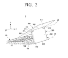
- FIG. 2 is a perspective view illustrating the portable device of FIG. 1 as seen from a different angle.
- FIG. 3 is a block diagram conceptually illustrating a controller equipped with the portable device of FIG. 1
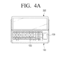
- FIGS. 4A , 4B and 4C are plan views illustrating various examples of a keyboard unit equipped with the portable device of FIG. 1 .
- FIG. 5A is a sectional view illustrating the portable device of FIG. 1 taken along a line V-V in FIG. 1 .
- FIG. 5B is a sectional view illustrating an alternative embodiment of the portable device of FIG. 5A .
- a portable device 1 is an electronic device to be easily carried when a user requires to bring the device 1 from one location to another, as well as to be used in a specific place in a stationary manner.
- the portable device 1 may include a keyboard unit 100, a display unit 200, a connection unit 300, and a controller 400.
- the keyboard unit 100 has a substantially rectangular plate shape.
- the keyboard unit 100 includes a plurality of input keys 120 which are exposed to a top surface 110 of the keyboard unit 100 and are in the form of buttons. The user may easily perform tasks such as text input, web surfing, etc., by using the input keys 120.
- the keyboard unit 100 may be equipped with a touch pad 130 that is placed on a right side of the keyboard unit 100 with the input keys 120.
- the keyboard unit 100 may be equipped with a touch pad 130' that is placed below the keyboard unit 100 with the input keys 120.
- the keyboard unit 100 may be equipped with a pointing stick 140 instead of the touch pad with the input keys 120.
- the display unit 200 may have a substantially rectangular plate shape.
- the display unit 200 is provided with a touch screen 210 on a front surface 211 of the display unit 200.
- the touch screen 210 functions as an input means by a user touch as well as an image display means.
- the display unit 200 may have various arrangements with respect to the keyboard unit 100 depending on user selection.
- the display unit 200 may be placed in a first arrangement to cover the keyboard unit 100 or a second arrangement to uncover the keyboard unit 100 (or not to cover the keyboard unit 100) by a user operation of moving the display unit 200 with respect to the key board unit 100. Appearance of the portable device 1 in the first and second arrangements will be described in detail later with reference to FIGS. 6 to 10 .
- the display unit 200 When the display unit 200 is placed in the first arrangement to cover the keyboard unit 100, the display unit 200 is placed to overlap the keyboard unit 100. Accordingly, the input keys 120 of the keyboard unit 100 are hidden by the display unit 200, and thus the input keys 120 cannot be used. However, the touch screen 210 of the display unit 200 remains exposed, and thus can be used.
- the portable device 1 when the display unit 200 is placed in this first described arrangement, the portable device 1 has a shape similar to a normal tablet computer. Accordingly, when the display unit 200 is placed in this first arrangement, the mode of the portable device 1 is referred to as a tablet mode.
- the touch screen 210 of the display unit 200 is maintained in the exposed (viewable) state so that the touch screen 210 can be used, and the keyboard unit 100 also can be used because the input keys 120 of the keyboard unit 100 are not covered by the display unit 200. Accordingly, when the display unit 200 is placed in the second described arrangement, the portable device 1 may have a form similar to a normal notebook computer. Therefore, when the display unit 200 is placed in the second described arrangement, the mode of the portable device 1 is referred to as a notebook mode.
- a lower end 220 of the display unit 200 can be inserted into at least one fixing groove formed on a top surface 110 of the keyboard unit 100 so that the position of the display unit 200 may be fixed.
- a first fixing groove 121 and a second fixing groove 122 are formed on the top surface 110 of the keyboard unit 100, and spaced apart from each other approximately as far from each other as a width of the display unit 200.
- the first fixing groove 121 may be placed at a left side of the keyboard unit 100 while the second fixing groove 122 may be placed at a right side of the keyboard unit 100.
- a left lower end 221 and a right lower end 222 of the display unit 200 may be inserted into the first fixing groove 121 and the second fixing groove 122, respectively.
- the first and second fixing grooves 121 and 122 may be concavely formed on the top surface 110 of the keyboard unit 100. However, other shapes of the fixing grooves 121 and 122 may be provided to correspond to the shapes of the left lower end 221 and a right lower end 222.
- the first and second fixing grooves 121 and 122 may be formed to be inclined at a predetermined angle (e.g. 50°, 60°, 70°, etc.) with respect to the top surface 110 of the keyboard unit 100. In other words, the first and second fixing grooves 121 and 122 may be formed to be inclined at the predetermined angle with respect to a Y direction across the keyboard unit 100.
- a predetermined angle e.g. 50°, 60°, 70°, etc.
- the display unit 200 may be maintained with the same inclination angle as the inclination angles of the first and second fixing grooves 121 and 122 with respect to the keyboard unit 100.
- the inclination angle may be variously selected depending on the design.
- the keyboard unit 100 may be divided into a first area 101 equipped with the input keys 120 and a second area 102 equipped with no input keys 120, in a direction (namely, Y direction) which is perpendicular to rotation axes X1 and X2 as illustrated in FIG. 2 and parallel to the keyboard unit 100.
- the first area 101 is placed in a front side of the keyboard unit 100
- the second area 102 is placed in a rear of the first area 101 as the first area 101 is positioned closest to a user.
- an area of the first area 101 is almost the same as that of the second area 102.
- the above-described first and second fixing grooves 121 and 122 are placed in a boundary area between the first area 101 and the second area 102. Accordingly, when the lower end 220 of the display unit 200 is inserted into the first and second fixing grooves 121 and 122, the lower end 220 of the display unit 200 is placed approximately at the center of the keyboard unit 100 (see, for example, FIG. 6 ).
- connection unit 300 supports the display unit 200 so that display unit 200 can be manipulated to cover or uncover the keyboard unit 100.
- the connection unit 300 is connected to each of the keyboard unit 100 and the display unit 200 so that the connection unit 300 can be moved relatively with respect to the each of the keyboard unit 100 and the display unit 200.
- connection unit 300 and the keyboard unit 100 are rotatably connected to each other and can each rotate relatively around a first rotation axis X1.
- the connection unit 300 and the display unit 200 are rotatably connected to each other and can each rotate relatively around a second rotation axis X2 parallel to the first rotation axis X1.
- the use mode switch (from the tablet mode to the notebook mode or from the notebook mode to the tablet mode) of the portable device 1 may be provided by and activated by the relative rotation between the connection unit 300 and the keyboard unit 100 and the relative rotation between the connection unit 300 and the display unit 200.
- connection unit 300 and the keyboard unit 100 are hinge-connected to each other to allow the relative rotation between the connection unit 300 and the keyboard unit 100
- connection unit 300 and the display unit 200 are hinge-connected to each other to allow the relative rotation between the connection unit 300 and the display unit 200.
- the hinge connection between the connection unit 300 and the keyboard unit 100 is performed by a first hinge unit (not illustrated)
- the hinge connection between the connection unit 300 and the display unit 200 is performed by a second hinge unit 310 (see FIG. 2 ).
- the first hinge unit not illustrated in the accompanying figures may have the same structure as that of the second hinge unit 310.
- each of the hinge units may use various types of conventional hinge structures which provide the intended purposes as described herein.
- connection unit 300 As illustrated in FIG. 2 , a first end 330 of the connection unit 300 is connected to a top end 150 of the keyboard unit 100 by the first hinge unit (not illustrated). A second end 340 of the connection unit 300 is connected to a rear surface 212 of the display unit 200 by the second hinge unit 310. Also illustrated in FIG. 2 , the second end 340 of the connection unit 300 may be connected approximately to a center of the rear surface 212 of the display unit 200.
- the first hinge unit and the second hinge unit 310 may have a free stop function. Accordingly, when the connection unit 300 is placed at some angle with respect to the keyboard unit 100 by the user manipulation, the connection unit 300 may maintain the angle set with respect to the keyboard unit 100 unless a force exceeding a threshold value is applied to the connection unit 300. Similarly, when the display unit 200 is placed at some angle with respect to the connection unit 300 by the user manipulation, the display unit 200 may maintain the angle set with respect to the connection unit 300 unless a force exceeding a threshold value is applied to the display unit 200. As illustrated in FIG. 2 , the display unit 200 may remain in a floating position above the keyboard unit 100 by the free stop function of the first and second hinges until the force exceeding the threshold value is applied to pivot the display unit 200.
- the connection unit 300 is received in a receiving groove 160 formed in the second area 102 (see FIG. 1 ) of the keyboard unit 100.
- the receiving groove 160 has a form corresponding to the connection unit 300 having a substantially rectangular plate shape, and a bottom surface 161 to face a front surface 351 of the connection unit 300 to be received within the receiving groove 160.
- connection unit 300 is rotated around the first rotation axis (X1) so as to be placed outside the receiving groove 160.
- the keyboard unit 100 may be provided with a receiving hole 170 with open top and bottom surfaces instead of the above-described receiving groove 160 to receive the connection unit 300.
- the receiving hole 170 is provided, there are advantages including that the keyboard unit 100 has a slimmer thickness and heat generated by the connection unit 300 may be emitted better as compared with the receiving groove 160.
- the connection unit 300 may include at least one input and output port to send and receive data with external devices. As illustrated in FIG. 2 , in the present embodiment, two input and output ports 361 and 362 are provided in an edge surface 370 of the connection unit 300. The type and number of the input and output ports 361 and 362 may be changed variously according to requirements of different exemplary embodiments.
- a controller 400 is configured to control operations of the portable device 1, and is disposed inside the above-described connection unit 300.
- the portable device 1 according to the present embodiment is distinguished from other existing portable devices in that the controller 400 is placed inside the connection unit 300.
- the controller 400 may include an interface unit 410, a storage unit 420, and a calculation unit 430.
- the interface unit 410 performs interfacing between the keyboard unit 100 and the display unit 200.
- the storage unit 420 stores programs required for operation of the portable device 1, and the calculation unit 430 executes the programs to control the operation of the portable device 1.
- FIG. 6 is a perspective view illustrating an arrangement of the portable device of FIG. 1 when the portable device is used in a notebook mode
- FIG. 7 is a side view illustrating the portable device of FIG. 6
- FIG. 8 is a perspective view illustrating another arrangement of the portable device of FIG. 1 when the portable device is used in a notebook mode
- FIG. 9 is a side view illustrating still another arrangement of the portable device of FIG. 1 when the portable device is used in a notebook mode
- FIG. 10 is a perspective view illustrating the portable device of FIG. 1 when the portable device is used in a tablet mode.
- FIGS. 6 and 7 will be explained.
- the portable device 1 When the portable device 1 is used in the notebook mode (namely, the display unit 200 is placed in the second arrangement not to cover the keyboard unit 100), the portable device 1 may have a first front viewing arrangement as illustrated in FIGS. 6 and 7 .
- an angle ⁇ between the first area 101 of the keyboard unit 100 and the display unit 200 is an obtuse angle
- an angle ⁇ between the connection unit 300 and the keyboard unit 100 and an angle ⁇ between the display unit 200 and the connection unit 300 are both an acute angle.
- ⁇ 120°
- ⁇ 60°.
- ⁇ , ⁇ , and ⁇ may be set differently depending on the embodiments.
- the user can use the keyboard unit 100 for tasks such as text input, web surfing, etc. Also, since the touch screen 210 of the display unit 200 is placed to face the front, the user may view the touch screen 210 from the front, and also may perform an input task through the touch screen 210.
- the left lower end 221 and right lower end 222 of the display unit 200 can be inserted into the first fixing groove 121 (see FIG. 1 ) and the second fixing groove 122 (see FIG. 1 ) of the keyboard unit 100, respectively, thereby being maintained in a fixed state.
- the display unit 200 according to the present embodiment is placed closer to the user by an approximate distance corresponding to the length L of the second area 102. Accordingly, when the portable device 1 is used in the notebook mode, touching the touch screen 210 is easier so the user is less likely to become fatigued due to having to extend a further distance to access and view the touch screen 210.
- the display unit 200 is supported by the connection unit 300 having almost the same width as the width W of the display unit 200, and the first hinge unit (not illustrated) and the second hinge unit 310 have the free stop functions, even if the user touches the touch screen 210, the display unit 200 is not moved, but may be maintained stably at any predetermined position.
- connection unit 300 since the connection unit 300 is placed in an inclined manner with respect to the keyboard unit 100, external surfaces of the connection unit 300 are exposed externally. Accordingly, heat generated in the connection unit 300 may be emitted outwardly more efficiently so that various electronic components configuring the controller 400 that are placed in the connection unit 300 may be prevented from being damaged by the heat.
- FIG. 8 will be described.
- the portable device 1 When the portable device 1 is used in the notebook mode (namely, the display unit 200 is placed in the second arrangement not to cover the keyboard unit 100), the portable device 1 may have a second front viewing arrangement as illustrated in FIG. 8 .
- the left and right lower ends 221 and 222 of the display unit 200 are separated from the first and second fixing grooves 121 and 122, and then the connection unit 300 and the display unit 200 are rotated slightly in the clockwise direction around the first and second rotation axes X1 and X2 so that the portable device 1 may be switched from the first front viewing arrangement as illustrated in FIGS. 6 and 7 to the second front viewing arrangement as illustrated in FIG. 8 .
- the display unit 200 is supported by the connection unit 300, and the connection unit 300 is supported by the keyboard unit 100.
- the connection unit 300 and the display unit 200 may be maintained in the fixed status by the free stop function of the first hinge unit (not illustrated) and the second hinge unit 310, as described above. Accordingly, if the user does not apply a force that exceeds the threshold value to the display unit 200 when using the touch screen, the display unit 200 and the connection unit 300 are maintained in the fixed status without movement.
- the second front viewing arrangement is the same as the first front viewing arrangement as described above in that both the input keys 120 of the keyboard unit 100 and the touch screen 210 of the display unit 200 can be used.
- the second front viewing arrangement is distinguished from the above-described first front viewing arrangement in that the left and right lower ends 221 and 222 of the display unit 200 are not inserted into the first and second fixing grooves 121 and 122 of the keyboard unit 100, but instead are separated from each other and are exposed externally.
- connection unit 300 since the external surfaces of the connection unit 300 are also exposed externally, the heat generated in the connection unit 300 may be emitted more efficiently so that various electronic components configuring the controller 400 that is built in the connection unit 300 may be prevented from being damaged by the heat.
- FIG. 9 will be described.
- the portable device 1 When the portable device 1 is used in the notebook mode (namely, the display unit 200 is placed in the second arrangement not to cover the keyboard unit 100), the portable device 1 may have a rear viewing arrangement as illustrated in FIG. 9 .
- the portable device 1 may be switched from the second front viewing arrangement as illustrated in FIG. 8 to the rear viewing arrangement as illustrated in FIG. 9 by further rotating the display unit 200 in the clockwise direction (relative to a viewing angle of FIGS. 2 , 8 and 9 ) around the second rotation axis X2 (see FIG. 2 ) until a rear surface 212 of the display unit 200 is in contact with a rear surface 352 of the connection unit 300.
- the angle between the connection unit 300 and the keyboard unit 100 may be set variously by rotation of the connection unit 300 around the first rotation axis X1 (see FIG. 2 ).
- the display unit 200 is supported by the connection unit 300, and the connection unit 300 is supported by the keyboard unit 100.
- the connection unit 300 and the display unit 200 may be maintained in the fixed status by the free stop function of the first hinge unit (not illustrated) and the second hinge unit 310. Accordingly, if the user does not apply a force that exceeds the threshold value to the display unit 200 when using the touch screen, the display unit 200 and the connection unit 300 are kept in the fixed status without movement.
- the rear watching arrangement is the same as the front viewing arrangements as described above in that both the input keys 120 of the keyboard unit 100 and the touch screen 210 of the display unit 200 can be used.
- the rear viewing arrangement is distinguished from the front viewing arrangements as described above in that the touch screen 210 can be used by another user located at the rear of the portable device 1 rather than the user located in front of the portable device 1 since the front surface 211 of the display unit 200 with the touch screen 210 faces the rear. Accordingly, when a first user located in front of the portable device 1 wants to show the touch screen 210 to a second user located at the rear of the portable device 1, the rear viewing arrangement may be used conveniently.
- the controller 400 reverses the top and bottom of an image which is being displayed on the touch screen 210.
- the controller 400 rotates the image being displayed on the touch screen 210 such that the image is rotated by 180 degrees along with the display unit 200.
- the controller 400 reverses the top and bottom of the image which is being displayed on the touch screen 210.
- a position sensor (not illustrated) may be disposed in the display unit 200 to detect the arrangement switching of the display unit 200. The controller 400 determines whether to reverse the position of the top and bottom of the image (rotate the image) based on an arrangement switching signal to be provided by the position sensor.
- connection unit 300 since the other external surfaces of the connection unit 300 except the rear surface are exposed externally, the heat generated in the connection unit 300 may be emitted efficiently so that various electronic components configuring the controller 400, which is disposed in the connection unit 300, may be prevented from being damaged by the heat.
- FIG. 10 will be described.
- the portable device 1 When the portable device 1 is used in the tablet mode (namely, the display unit 200 is placed in the first arrangement to cover the keyboard unit 100), the portable device 1 may have a shape as illustrated in FIG. 10 .
- the portable device 1 may be switched from the notebook mode to the tablet mode by switching the display unit 200 from the second front viewing arrangement as illustrated in FIG. 8 or the rear viewing arrangement as illustrated in FIG. 9 to the arrangement as illustrated in FIG. 10 .
- connection unit 300 When being changed from the second front viewing arrangement as illustrated in FIG. 8 to the arrangement as illustrated in FIG. 10 , the connection unit 300 is rotated in the counterclockwise direction (relatively with respect to the viewing angle of FIGS. 2 , 8 and 9 ) until the connection unit 300 is received inside the receiving groove 160 of the keyboard unit 100, and the display unit 200 is rotated in the clockwise direction until the rear surface 212 of the display unit 200 is in contact with the rear surface 352 of the connection unit 300 so that the use mode of the portable device 1 may be switched to the tablet mode as illustrated in FIG. 10 .
- connection unit 300 when being changed from the rear viewing arrangement as illustrated in FIG. 9 to the arrangement as illustrated in FIG. 10 , the connection unit 300 is rotated in the counterclockwise direction until the connection unit 300 is received inside the receiving groove 160 of the keyboard unit 100 without relative movement between the display unit 200 and the connection unit 300 so that the use mode of the portable device 1 may be switched to the tablet mode as illustrated in FIG. 10 .
- the angle ⁇ between the keyboard unit 100 and the display unit 200 and the angle ⁇ between the display unit 200 and the connection unit 300 are 180°, respectively.
- the angle ⁇ between the connection unit 300 and the keyboard unit 100 is o°.
- the display unit 200 is supported by the connection unit 300 and keyboard unit 100, and the connection unit 300 is supported by the keyboard unit 100.
- the connection unit 300 and the display unit 200 may be maintained in the fixed status by the free stop function of the first hinge unit (not illustrated) and the second hinge unit 310.
- the input keys 120 of the keyboard unit 100 cannot be used, but the touch screen 210 of the display unit 200 is exposed so as to be accessed and used.
- the user when the user wants to switch the portable device 1 from the tablet mode as illustrated in FIG. 10 to one of the notebook modes as illustrated in FIGS. 6 , 8 and 9 , the user separates the display unit 200 slightly from the keyboard unit 100, and then adjusts properly the above-described angles ⁇ , ⁇ , and ⁇ by rotating the connection unit 300 and the display unit 200 around the first and second rotation axes X1 and X2. Because the switching principle from the tablet mode to the notebook mode may be easily understood from the above-described switching principle from the notebook mode to the tablet mode, a detailed description thereof will be omitted.
- the portable device 1 may be placed in the notebook mode or the tablet mode depending on the user selection.
- the display unit 200 may be set in the front viewing arrangement or the rear viewing arrangement. In the front or rear viewing arrangement, the display unit 200 may be stably supported by the connection unit 300.
- the portable device 1 is distinguished from the conventional portable devices in that the controller 400 is placed inside the connection unit 300. Since the controller 400 is placed inside the connection unit 300, electronic components configuring the controller 400 may effectively be prevented from the heat, especially when the portable device 1 is used in the notebook mode.
Abstract
Description
- The present invention relates to a portable device. More particularly, the present invention relates to a portable device that can be used like a notebook computer or a tablet computer depending on user selection.
- Notebook computers and tablet computers are well-known portable devices. Generally, the notebook computer has an advantage of fast text input by using a keyboard, and the tablet computer has an advantage of a more compact appearance by using a touch screen instead of the keyboard.
- Recently, new types of portable devices which include advantages of both the notebook computer and tablet computer by being designed to be used like the notebook computer or the tablet computer, depending on the user selection, are being launched.
- The new types of portable devices are equipped with a display unit with a touch screen. The touch screen is provided to be touchable by a user even when the portable device is used like the notebook computer as well as when the portable device is used like the tablet computer. Accordingly, when the portable device is used like the notebook computer, ways which can stably support the display unit so that the display unit is not moved even if the user touches the touch screen are required.
- In addition, as general electronic products, the above-described new types of portable devices require ways to protect internal electronic components thereof from heat by improving heat radiation performance thereof.
- The present disclosure has been developed in order to overcome the above drawbacks and other problems associated with the conventional arrangement. An exemplary embodiment of the present disclosure relates to a new type of portable device that can stably support a display unit and has an improved heat radiation performance.
- Additional features and utilities of the present general inventive concept will be set forth in part in the description which follows and, in part, will be obvious from the description, or may be learned by practice of the general inventive concept.
- Exemplary embodiments of the present disclosure can substantially be achieved by providing a portable device, which may include a keyboard unit, a display unit, a connection unit which is connected to each of the keyboard unit and the display unit, moves relatively with respect to each of the keyboard unit and the display unit, and supports the display unit so that the display unit covers or uncovers the keyboard unit, and a controller which is placed inside the connection unit and controls operation of the portable device.
- The display unit may be placed in a first arrangement to cover the keyboard unit or a second arrangement to uncover the keyboard unit depending on user selection.
- A touch screen may be equipped in a front surface of the display unit, and, when the display unit is placed in the first arrangement and the second arrangement, the touch screen may be maintained in a viewable state.
- The connection unit may be connected to the keyboard unit and can be rotated around a first rotation axis, and the display unit may be connected to the connection unit and can be rotated around a second rotation axis parallel to the first rotation axis.
- The connection unit may be hinge-connected to the keyboard unit, and the display unit may be hinge-connected to the connection unit.
- When the display unit is placed in the second arrangement, the connection unit may be placed inclinedly with respect to the keyboard unit so that external surfaces of the connection unit are exposed externally.
- The keyboard unit may include a receiving groove to receive the connection unit when the connection unit is placed in the first arrangement.
- The keyboard unit may include a receiving hole which receives the connection unit when the connection unit is placed in the first arrangement, and may have open top and bottom surfaces.
A top surface of the keyboard unit may include at least one fixing groove in which a lower end of the display unit is inserted when the display unit is placed in the second arrangement. - The at least one fixing groove may include a first fixing groove in which a left lower end of the display unit is inserted and a second fixing groove in which a right lower end of the display unit is inserted.
- The keyboard unit may be divided into a first area and a second area in a direction parallel to the keyboard unit and vertical to the first rotation axis, the first area may be equipped with input keys of the keyboard unit, and the second area may not be equipped with the input keys, and the at least one fixing groove may be placed at a boundary area between the first area and the second area.
- The second arrangement of the display unit may include a front viewing arrangement in which the touch screen can be viewed from a front side of the portable device, and a rear viewing arrangement in which the touch screen can be viewed from a rear side of the portable device.
- When the display unit is switched from the front viewing arrangement to the rear viewing arrangement or when the display unit is switched from the rear viewing arrangement to the front viewing arrangement, the controller may reverse the top and bottom of an image that is being displayed on the touch screen.
- When the display unit is placed in the rear viewing arrangement, a rear surface of the display unit may be in contact with a rear surface of the connection unit.
- One end of the connection unit may be connected to an end of the keyboard unit, and the other end of the connection unit may be connected to a center portion of a rear surface of the display unit.
- The controller may include an interface unit configured to perform interfacing with the keyboard unit and the display unit, a storage unit configured to store programs required for the operation of the portable device, and a calculation unit configured to execute the programs to control the operation of the portable device.
- The connection unit may include at least one input and output port to send and receive data with at least one external device.
- Other utilities and salient features of the present disclosure will become apparent from the following detailed description, which, taken in conjunction with the annexed drawings, discloses preferred embodiments.
- These and/or other aspects and advantages of the present disclosure will become apparent and more readily appreciated from the following description of the embodiments, taken in conjunction with the accompanying drawings of which:
-
FIG. 1 is a perspective view illustrating a portable device according to an embodiment of the present disclosure; -
FIG. 2 is a perspective view illustrating the portable device ofFIG. 1 as seen from a different angle; -
FIG. 3 is a block diagram conceptually illustrating a controller equipped with the portable device ofFIG. 1 ; -
FIGS. 4A ,4B and4C are plan views illustrating various examples of a keyboard unit equipped with the portable device ofFIG. 1 ; -
FIG. 5A is a sectional view illustrating the portable device ofFIG. 1 taken along a line V-V inFIG. 1 ; -
FIG. 5B is a sectional view illustrating an alternative embodiment of the portable device ofFIG. 5A ; -
FIG. 6 is a perspective view illustrating an arrangement of the portable device ofFIG. 1 when the portable device is used in a notebook mode; -
FIG. 7 is a side view illustrating the portable device ofFIG. 6 ; -
FIG. 8 is a perspective view illustrating another arrangement of the portable device of -
FIG. 1 when the portable device is used in a notebook mode; -
FIG. 9 is a side view illustrating still another arrangement of the portable device ofFIG. 1 when the portable device is used in a notebook mode; and -
FIG. 10 is a perspective view illustrating the portable device ofFIG. 1 when the portable device is used in a tablet mode. - Throughout the drawings, like reference numerals will be understood to refer to like parts, components and structures.
- Hereinafter, certain exemplary embodiments of the present disclosure will be described in detail with reference to the accompanying drawings.
- The matters defined herein, such as a detailed construction and elements thereof, are provided to assist in a comprehensive understanding of this description. Thus, it is apparent that exemplary embodiments may be carried out without those defined matters. Also, well-known functions or constructions are omitted to provide a clear and concise description of exemplary embodiments. Further, dimensions of various elements in the accompanying drawings may be arbitrarily increased or decreased for assisting in a comprehensive understanding.
-
FIG. 1 is a perspective view illustrating a portable device according to an exemplary embodiment of the present disclosure;FIG. 2 is a perspective view illustrating the portable device ofFIG. 1 as seen from a different angle.FIG. 3 is a block diagram conceptually illustrating a controller equipped with the portable device ofFIG. 1 ;FIGS. 4A ,4B and4C are plan views illustrating various examples of a keyboard unit equipped with the portable device ofFIG. 1 .FIG. 5A is a sectional view illustrating the portable device ofFIG. 1 taken along a line V-V inFIG. 1 .FIG. 5B is a sectional view illustrating an alternative embodiment of the portable device ofFIG. 5A . - Referring to
FIGS. 1 ,2 , and3 , aportable device 1 according to an embodiment of the present disclosure is an electronic device to be easily carried when a user requires to bring thedevice 1 from one location to another, as well as to be used in a specific place in a stationary manner. Theportable device 1 may include akeyboard unit 100, adisplay unit 200, aconnection unit 300, and acontroller 400. - The
keyboard unit 100 has a substantially rectangular plate shape. Thekeyboard unit 100 includes a plurality ofinput keys 120 which are exposed to atop surface 110 of thekeyboard unit 100 and are in the form of buttons. The user may easily perform tasks such as text input, web surfing, etc., by using theinput keys 120. - Alternatively, as illustrated in
FIG. 4A , thekeyboard unit 100 may be equipped with atouch pad 130 that is placed on a right side of thekeyboard unit 100 with theinput keys 120. As illustrated inFIG. 4B , thekeyboard unit 100 may be equipped with a touch pad 130' that is placed below thekeyboard unit 100 with theinput keys 120. As illustrated inFIG. 4C , thekeyboard unit 100 may be equipped with apointing stick 140 instead of the touch pad with theinput keys 120.
Thedisplay unit 200 may have a substantially rectangular plate shape. Thedisplay unit 200 is provided with atouch screen 210 on afront surface 211 of thedisplay unit 200. Thetouch screen 210 functions as an input means by a user touch as well as an image display means. - The
display unit 200 may have various arrangements with respect to thekeyboard unit 100 depending on user selection. In detail, thedisplay unit 200 may be placed in a first arrangement to cover thekeyboard unit 100 or a second arrangement to uncover the keyboard unit 100 (or not to cover the keyboard unit 100) by a user operation of moving thedisplay unit 200 with respect to thekey board unit 100. Appearance of theportable device 1 in the first and second arrangements will be described in detail later with reference toFIGS. 6 to 10 . - When the
display unit 200 is placed in the first arrangement to cover thekeyboard unit 100, thedisplay unit 200 is placed to overlap thekeyboard unit 100. Accordingly, theinput keys 120 of thekeyboard unit 100 are hidden by thedisplay unit 200, and thus theinput keys 120 cannot be used. However, thetouch screen 210 of thedisplay unit 200 remains exposed, and thus can be used. Here, when thedisplay unit 200 is placed in this first described arrangement, theportable device 1 has a shape similar to a normal tablet computer. Accordingly, when thedisplay unit 200 is placed in this first arrangement, the mode of theportable device 1 is referred to as a tablet mode. - When the
display unit 200 is placed in the second arrangement not to cover thekeyboard unit 100, thetouch screen 210 of thedisplay unit 200 is maintained in the exposed (viewable) state so that thetouch screen 210 can be used, and thekeyboard unit 100 also can be used because theinput keys 120 of thekeyboard unit 100 are not covered by thedisplay unit 200. Accordingly, when thedisplay unit 200 is placed in the second described arrangement, theportable device 1 may have a form similar to a normal notebook computer. Therefore, when thedisplay unit 200 is placed in the second described arrangement, the mode of theportable device 1 is referred to as a notebook mode. - When the
portable device 1 is used in the notebook mode, alower end 220 of thedisplay unit 200 can be inserted into at least one fixing groove formed on atop surface 110 of thekeyboard unit 100 so that the position of thedisplay unit 200 may be fixed. In more detail, afirst fixing groove 121 and asecond fixing groove 122 are formed on thetop surface 110 of thekeyboard unit 100, and spaced apart from each other approximately as far from each other as a width of thedisplay unit 200. In other words, thefirst fixing groove 121 may be placed at a left side of thekeyboard unit 100 while thesecond fixing groove 122 may be placed at a right side of thekeyboard unit 100. A leftlower end 221 and a rightlower end 222 of thedisplay unit 200 may be inserted into thefirst fixing groove 121 and thesecond fixing groove 122, respectively. - The first and second fixing
grooves top surface 110 of thekeyboard unit 100. However, other shapes of the fixinggrooves lower end 221 and a rightlower end 222. The first and second fixinggrooves top surface 110 of thekeyboard unit 100. In other words, the first and second fixinggrooves keyboard unit 100. Accordingly, when theportable device 1 is used in the notebook mode, if thelower end 220 of thedisplay unit 200 is inserted in the first and second fixinggrooves display unit 200 may be maintained with the same inclination angle as the inclination angles of the first and second fixinggrooves keyboard unit 100. The inclination angle may be variously selected depending on the design. - The
keyboard unit 100 may be divided into afirst area 101 equipped with theinput keys 120 and asecond area 102 equipped with noinput keys 120, in a direction (namely, Y direction) which is perpendicular to rotation axes X1 and X2 as illustrated inFIG. 2 and parallel to thekeyboard unit 100. Here, thefirst area 101 is placed in a front side of thekeyboard unit 100, and thesecond area 102 is placed in a rear of thefirst area 101 as thefirst area 101 is positioned closest to a user. In the present embodiment, an area of thefirst area 101 is almost the same as that of thesecond area 102. The above-described first and second fixinggrooves first area 101 and thesecond area 102. Accordingly, when thelower end 220 of thedisplay unit 200 is inserted into the first and second fixinggrooves lower end 220 of thedisplay unit 200 is placed approximately at the center of the keyboard unit 100 (see, for example,FIG. 6 ). - The
connection unit 300 supports thedisplay unit 200 so thatdisplay unit 200 can be manipulated to cover or uncover thekeyboard unit 100. Theconnection unit 300 is connected to each of thekeyboard unit 100 and thedisplay unit 200 so that theconnection unit 300 can be moved relatively with respect to the each of thekeyboard unit 100 and thedisplay unit 200. - In more detail, the
connection unit 300 and thekeyboard unit 100 are rotatably connected to each other and can each rotate relatively around a first rotation axis X1. Theconnection unit 300 and thedisplay unit 200 are rotatably connected to each other and can each rotate relatively around a second rotation axis X2 parallel to the first rotation axis X1. The use mode switch (from the tablet mode to the notebook mode or from the notebook mode to the tablet mode) of theportable device 1 may be provided by and activated by the relative rotation between theconnection unit 300 and thekeyboard unit 100 and the relative rotation between theconnection unit 300 and thedisplay unit 200. - The
connection unit 300 and thekeyboard unit 100 are hinge-connected to each other to allow the relative rotation between theconnection unit 300 and thekeyboard unit 100, and theconnection unit 300 and thedisplay unit 200 are hinge-connected to each other to allow the relative rotation between theconnection unit 300 and thedisplay unit 200. Here, the hinge connection between theconnection unit 300 and thekeyboard unit 100 is performed by a first hinge unit (not illustrated), and the hinge connection between theconnection unit 300 and thedisplay unit 200 is performed by a second hinge unit 310 (seeFIG. 2 ). The first hinge unit not illustrated in the accompanying figures may have the same structure as that of thesecond hinge unit 310. Alternatively, each of the hinge units may use various types of conventional hinge structures which provide the intended purposes as described herein. - As illustrated in
FIG. 2 , afirst end 330 of theconnection unit 300 is connected to atop end 150 of thekeyboard unit 100 by the first hinge unit (not illustrated). Asecond end 340 of theconnection unit 300 is connected to arear surface 212 of thedisplay unit 200 by thesecond hinge unit 310. Also illustrated inFIG. 2 , thesecond end 340 of theconnection unit 300 may be connected approximately to a center of therear surface 212 of thedisplay unit 200. - The first hinge unit and the
second hinge unit 310 may have a free stop function. Accordingly, when theconnection unit 300 is placed at some angle with respect to thekeyboard unit 100 by the user manipulation, theconnection unit 300 may maintain the angle set with respect to thekeyboard unit 100 unless a force exceeding a threshold value is applied to theconnection unit 300. Similarly, when thedisplay unit 200 is placed at some angle with respect to theconnection unit 300 by the user manipulation, thedisplay unit 200 may maintain the angle set with respect to theconnection unit 300 unless a force exceeding a threshold value is applied to thedisplay unit 200. As illustrated inFIG. 2 , thedisplay unit 200 may remain in a floating position above thekeyboard unit 100 by the free stop function of the first and second hinges until the force exceeding the threshold value is applied to pivot thedisplay unit 200. - When the
display unit 200 is placed in the first arrangement to cover the keyboard unit 100 (namely, when theportable device 1 is used in the tablet mode), theconnection unit 300 is received in a receivinggroove 160 formed in the second area 102 (seeFIG. 1 ) of thekeyboard unit 100. Referring toFIGS. 1 and5A , the receivinggroove 160 has a form corresponding to theconnection unit 300 having a substantially rectangular plate shape, and abottom surface 161 to face afront surface 351 of theconnection unit 300 to be received within the receivinggroove 160. On the other hand, when thedisplay unit 200 is placed in the second arrangement to uncover the keyboard unit 100 (namely, when theportable device 1 is used in the notebook mode), theconnection unit 300 is rotated around the first rotation axis (X1) so as to be placed outside the receivinggroove 160. - As illustrated in
FIG. 5B , thekeyboard unit 100 may be provided with a receivinghole 170 with open top and bottom surfaces instead of the above-describedreceiving groove 160 to receive theconnection unit 300. When the receivinghole 170 is provided, there are advantages including that thekeyboard unit 100 has a slimmer thickness and heat generated by theconnection unit 300 may be emitted better as compared with the receivinggroove 160. - The
connection unit 300 may include at least one input and output port to send and receive data with external devices. As illustrated inFIG. 2 , in the present embodiment, two input andoutput ports edge surface 370 of theconnection unit 300. The type and number of the input andoutput ports - As illustrated in
FIG. 3 , acontroller 400 is configured to control operations of theportable device 1, and is disposed inside the above-describedconnection unit 300. Theportable device 1 according to the present embodiment is distinguished from other existing portable devices in that thecontroller 400 is placed inside theconnection unit 300. - Also as illustrated in
FIG. 3 , thecontroller 400 may include aninterface unit 410, astorage unit 420, and acalculation unit 430. Theinterface unit 410 performs interfacing between thekeyboard unit 100 and thedisplay unit 200. Thestorage unit 420 stores programs required for operation of theportable device 1, and thecalculation unit 430 executes the programs to control the operation of theportable device 1. - Hereinafter, operations of the
portable device 1 as described above will be described in more detail with reference toFIGS. 6 to 10 . -
FIG. 6 is a perspective view illustrating an arrangement of the portable device ofFIG. 1 when the portable device is used in a notebook mode,FIG. 7 is a side view illustrating the portable device ofFIG. 6 .FIG. 8 is a perspective view illustrating another arrangement of the portable device ofFIG. 1 when the portable device is used in a notebook mode, andFIG. 9 is a side view illustrating still another arrangement of the portable device ofFIG. 1 when the portable device is used in a notebook mode.FIG. 10 , on the other hand, is a perspective view illustrating the portable device ofFIG. 1 when the portable device is used in a tablet mode. - First,
FIGS. 6 and7 will be explained. - When the
portable device 1 is used in the notebook mode (namely, thedisplay unit 200 is placed in the second arrangement not to cover the keyboard unit 100), theportable device 1 may have a first front viewing arrangement as illustrated inFIGS. 6 and7 . - In the first front viewing arrangement, an angle α between the
first area 101 of thekeyboard unit 100 and thedisplay unit 200 is an obtuse angle, and an angle β between theconnection unit 300 and thekeyboard unit 100 and an angle γ between thedisplay unit 200 and theconnection unit 300 are both an acute angle. For example, α = 120°, and = γ = 60°. However, α, β, and γ may be set differently depending on the embodiments. - In the first front viewing arrangement, since the
input keys 120 of thekeyboard unit 100 are not covered by thedisplay unit 200, but are exposed externally, the user can use thekeyboard unit 100 for tasks such as text input, web surfing, etc. Also, since thetouch screen 210 of thedisplay unit 200 is placed to face the front, the user may view thetouch screen 210 from the front, and also may perform an input task through thetouch screen 210. - In the first front viewing arrangement, the left
lower end 221 and rightlower end 222 of thedisplay unit 200 can be inserted into the first fixing groove 121 (seeFIG. 1 ) and the second fixing groove 122 (seeFIG. 1 ) of thekeyboard unit 100, respectively, thereby being maintained in a fixed state. Referring toFIG. 7 , since the first and second fixinggrooves first area 101 and thesecond area 102 of thekeyboard unit 100 as described above, compared with a display unit of the conventional notebook computer (see dotted outline illustrating the positioning of a conventional display 20), thedisplay unit 200 according to the present embodiment is placed closer to the user by an approximate distance corresponding to the length L of thesecond area 102. Accordingly, when theportable device 1 is used in the notebook mode, touching thetouch screen 210 is easier so the user is less likely to become fatigued due to having to extend a further distance to access and view thetouch screen 210. - Also, in the first front watching arrangement, since the
display unit 200 is supported by theconnection unit 300 having almost the same width as the width W of thedisplay unit 200, and the first hinge unit (not illustrated) and thesecond hinge unit 310 have the free stop functions, even if the user touches thetouch screen 210, thedisplay unit 200 is not moved, but may be maintained stably at any predetermined position. - Also, in the first front viewing arrangement, since the
connection unit 300 is placed in an inclined manner with respect to thekeyboard unit 100, external surfaces of theconnection unit 300 are exposed externally. Accordingly, heat generated in theconnection unit 300 may be emitted outwardly more efficiently so that various electronic components configuring thecontroller 400 that are placed in theconnection unit 300 may be prevented from being damaged by the heat. - Next,
FIG. 8 will be described. - When the
portable device 1 is used in the notebook mode (namely, thedisplay unit 200 is placed in the second arrangement not to cover the keyboard unit 100), theportable device 1 may have a second front viewing arrangement as illustrated inFIG. 8 . - In this exemplary embodiment, the left and right lower ends 221 and 222 of the
display unit 200 are separated from the first and second fixinggrooves connection unit 300 and thedisplay unit 200 are rotated slightly in the clockwise direction around the first and second rotation axes X1 and X2 so that theportable device 1 may be switched from the first front viewing arrangement as illustrated inFIGS. 6 and7 to the second front viewing arrangement as illustrated inFIG. 8 . - In the second front viewing arrangement, the
display unit 200 is supported by theconnection unit 300, and theconnection unit 300 is supported by thekeyboard unit 100. Theconnection unit 300 and thedisplay unit 200 may be maintained in the fixed status by the free stop function of the first hinge unit (not illustrated) and thesecond hinge unit 310, as described above. Accordingly, if the user does not apply a force that exceeds the threshold value to thedisplay unit 200 when using the touch screen, thedisplay unit 200 and theconnection unit 300 are maintained in the fixed status without movement. - The second front viewing arrangement is the same as the first front viewing arrangement as described above in that both the
input keys 120 of thekeyboard unit 100 and thetouch screen 210 of thedisplay unit 200 can be used. However, the second front viewing arrangement is distinguished from the above-described first front viewing arrangement in that the left and right lower ends 221 and 222 of thedisplay unit 200 are not inserted into the first and second fixinggrooves keyboard unit 100, but instead are separated from each other and are exposed externally. - In the second front viewing arrangement, since the external surfaces of the
connection unit 300 are also exposed externally, the heat generated in theconnection unit 300 may be emitted more efficiently so that various electronic components configuring thecontroller 400 that is built in theconnection unit 300 may be prevented from being damaged by the heat. - Next,
FIG. 9 will be described. - When the
portable device 1 is used in the notebook mode (namely, thedisplay unit 200 is placed in the second arrangement not to cover the keyboard unit 100), theportable device 1 may have a rear viewing arrangement as illustrated inFIG. 9 . - The
portable device 1 may be switched from the second front viewing arrangement as illustrated inFIG. 8 to the rear viewing arrangement as illustrated inFIG. 9 by further rotating thedisplay unit 200 in the clockwise direction (relative to a viewing angle ofFIGS. 2 ,8 and9 ) around the second rotation axis X2 (seeFIG. 2 ) until arear surface 212 of thedisplay unit 200 is in contact with arear surface 352 of theconnection unit 300. Here, the angle between theconnection unit 300 and thekeyboard unit 100 may be set variously by rotation of theconnection unit 300 around the first rotation axis X1 (seeFIG. 2 ). - In the rear viewing arrangement, the
display unit 200 is supported by theconnection unit 300, and theconnection unit 300 is supported by thekeyboard unit 100. Theconnection unit 300 and thedisplay unit 200 may be maintained in the fixed status by the free stop function of the first hinge unit (not illustrated) and thesecond hinge unit 310. Accordingly, if the user does not apply a force that exceeds the threshold value to thedisplay unit 200 when using the touch screen, thedisplay unit 200 and theconnection unit 300 are kept in the fixed status without movement. - The rear watching arrangement is the same as the front viewing arrangements as described above in that both the
input keys 120 of thekeyboard unit 100 and thetouch screen 210 of thedisplay unit 200 can be used. However, the rear viewing arrangement is distinguished from the front viewing arrangements as described above in that thetouch screen 210 can be used by another user located at the rear of theportable device 1 rather than the user located in front of theportable device 1 since thefront surface 211 of thedisplay unit 200 with thetouch screen 210 faces the rear. Accordingly, when a first user located in front of theportable device 1 wants to show thetouch screen 210 to a second user located at the rear of theportable device 1, the rear viewing arrangement may be used conveniently. - On the other hand, when the
display unit 200 is switched from the front viewing arrangement to the rear viewing arrangement, thecontroller 400 reverses the top and bottom of an image which is being displayed on thetouch screen 210. In other words, thecontroller 400 rotates the image being displayed on thetouch screen 210 such that the image is rotated by 180 degrees along with thedisplay unit 200. Likewise, when thedisplay unit 200 is switched from the rear viewing arrangement to the front viewing arrangement, thecontroller 400 reverses the top and bottom of the image which is being displayed on thetouch screen 210. A position sensor (not illustrated) may be disposed in thedisplay unit 200 to detect the arrangement switching of thedisplay unit 200. Thecontroller 400 determines whether to reverse the position of the top and bottom of the image (rotate the image) based on an arrangement switching signal to be provided by the position sensor. - In the rear viewing arrangement, since the other external surfaces of the
connection unit 300 except the rear surface are exposed externally, the heat generated in theconnection unit 300 may be emitted efficiently so that various electronic components configuring thecontroller 400, which is disposed in theconnection unit 300, may be prevented from being damaged by the heat. - Next,
FIG. 10 will be described. - When the
portable device 1 is used in the tablet mode (namely, thedisplay unit 200 is placed in the first arrangement to cover the keyboard unit 100), theportable device 1 may have a shape as illustrated inFIG. 10 . - The
portable device 1 may be switched from the notebook mode to the tablet mode by switching thedisplay unit 200 from the second front viewing arrangement as illustrated inFIG. 8 or the rear viewing arrangement as illustrated inFIG. 9 to the arrangement as illustrated inFIG. 10 . - When being changed from the second front viewing arrangement as illustrated in
FIG. 8 to the arrangement as illustrated inFIG. 10 , theconnection unit 300 is rotated in the counterclockwise direction (relatively with respect to the viewing angle ofFIGS. 2 ,8 and9 ) until theconnection unit 300 is received inside the receivinggroove 160 of thekeyboard unit 100, and thedisplay unit 200 is rotated in the clockwise direction until therear surface 212 of thedisplay unit 200 is in contact with therear surface 352 of theconnection unit 300 so that the use mode of theportable device 1 may be switched to the tablet mode as illustrated inFIG. 10 . - Also, when being changed from the rear viewing arrangement as illustrated in
FIG. 9 to the arrangement as illustrated inFIG. 10 , theconnection unit 300 is rotated in the counterclockwise direction until theconnection unit 300 is received inside the receivinggroove 160 of thekeyboard unit 100 without relative movement between thedisplay unit 200 and theconnection unit 300 so that the use mode of theportable device 1 may be switched to the tablet mode as illustrated inFIG. 10 . - In the tablet mode, the angle α between the
keyboard unit 100 and thedisplay unit 200 and the angle γ between thedisplay unit 200 and theconnection unit 300 are 180°, respectively. The angle β between theconnection unit 300 and thekeyboard unit 100 is o°. - In the tablet mode, the
display unit 200 is supported by theconnection unit 300 andkeyboard unit 100, and theconnection unit 300 is supported by thekeyboard unit 100. Theconnection unit 300 and thedisplay unit 200 may be maintained in the fixed status by the free stop function of the first hinge unit (not illustrated) and thesecond hinge unit 310. - In the tablet mode, since the
keyboard unit 100 is covered by thedisplay unit 200, theinput keys 120 of thekeyboard unit 100 cannot be used, but thetouch screen 210 of thedisplay unit 200 is exposed so as to be accessed and used. - On the other hand, when the user wants to switch the
portable device 1 from the tablet mode as illustrated inFIG. 10 to one of the notebook modes as illustrated inFIGS. 6 ,8 and9 , the user separates thedisplay unit 200 slightly from thekeyboard unit 100, and then adjusts properly the above-described angles α, β, and γ by rotating theconnection unit 300 and thedisplay unit 200 around the first and second rotation axes X1 and X2. Because the switching principle from the tablet mode to the notebook mode may be easily understood from the above-described switching principle from the notebook mode to the tablet mode, a detailed description thereof will be omitted. - As described above, the
portable device 1 according to an embodiment of the present disclosure may be placed in the notebook mode or the tablet mode depending on the user selection. In the notebook mode, thedisplay unit 200 may be set in the front viewing arrangement or the rear viewing arrangement. In the front or rear viewing arrangement, thedisplay unit 200 may be stably supported by theconnection unit 300. - Also, the
portable device 1 according to an embodiment of the present disclosure is distinguished from the conventional portable devices in that thecontroller 400 is placed inside theconnection unit 300. Since thecontroller 400 is placed inside theconnection unit 300, electronic components configuring thecontroller 400 may effectively be prevented from the heat, especially when theportable device 1 is used in the notebook mode. - Although a few embodiments of the present general inventive concept have been shown and described, it will be appreciated by those skilled in the art that changes may be made in these embodiments without departing from the principles of the general inventive concept, the scope of which is defined in the appended claims.
Claims (15)
- A portable device comprising:a keyboard unit;a display unit;a connection unit configured to be connected to each of the keyboard unit and the display unit, and arranged to move relative to each of the keyboard unit and the display unit, and to support the display unit so that the display unit covers or uncovers the keyboard unit; anda controller disposed inside the connection unit and to control operations of the portable device.
- The portable device of claim 1, wherein the display unit is placed in a first arrangement to cover the keyboard unit or a second arrangement to uncover the keyboard unit depending on user selection.
- The portable device of claim 2, wherein
a touch screen is equipped in a front surface of the display unit, and
when the display unit is placed in the first arrangement and the second arrangement, the touch screen is maintained in a viewable state. - The portable device of any one of the preceding claims, wherein:the connection unit is connected to the keyboard unit and can be rotated around a first rotation axis, andthe display unit is connected to the connection unit and can be rotated around a second rotation axis parallel to the first rotation axis.
- The portable device of any one of the preceding claims, wherein:the connection unit is hinge-connected to the keyboard unit, andthe display unit is hinge-connected to the connection unit.
- The portable device of any one of claims 2 to 5, wherein when the display unit is placed in the second arrangement, the connection unit is placed inclined with respect to the keyboard unit so that external surfaces of the connection unit are exposed externally.
- The portable device of any one of claims 2 to 6, wherein the keyboard unit comprises a receiving groove to receive the connection unit when the connection unit is placed in the first arrangement.
- The portable device of any one of claims 2 to 7, wherein the keyboard unit comprises a receiving hole which receives the connection unit when the connection unit is placed in the first arrangement and has open top and bottom surfaces.
- The portable device of any one of claims 2 to 8, wherein a top surface of the keyboard unit comprises at least one fixing groove in which a lower end of the display unit is inserted when the display unit is placed in the second arrangement.
- The portable device of claim 9, wherein the at least one fixing groove comprises:a first fixing groove in which a left lower end of the display unit is inserted; anda second fixing groove in which a right lower end of the display unit is inserted.
- The portable device of claim 9 or 10, wherein:the keyboard unit is divided into a first area and a second area in a direction parallel to the keyboard unit and vertical to the first rotation axis, the first area is equipped with input keys of the keyboard unit, and the second area is not equipped with the input keys, andthe at least one fixing groove is placed at a boundary area between the first area and the second area.
- The portable device of any one of claims 2 to 11, wherein the second arrangement of the display unit comprises:a front viewing arrangement in which the touch screen can be watched from a front side of the portable device, anda rear viewing arrangement in which the touch screen can be watched from a rear side of the portable device.
- The portable device of claim 12, wherein, when the display unit is switched from the front viewing arrangement to the rear viewing arrangement or when the display unit is switched from the rear viewing arrangement to the front viewing arrangement, the controller reverses top and bottom of an image that is being displayed on the touch screen.
- The portable device of claim 12 or 13, wherein, when the display unit is placed in the rear viewing arrangement, a rear surface of the display unit is in contact with a rear surface of the connection unit.
- The portable device of any of the preceding claims, wherein one end of the connection unit is connected to an end of the keyboard unit, and the other end of the connection unit is connected to a centre portion of a rear surface of the display unit.
Applications Claiming Priority (2)
| Application Number | Priority Date | Filing Date | Title |
|---|---|---|---|
| KR20120094550 | 2012-08-28 | ||
| KR1020130033770A KR102091007B1 (en) | 2012-08-28 | 2013-03-28 | Portable device |
Publications (3)
| Publication Number | Publication Date |
|---|---|
| EP2703935A2 true EP2703935A2 (en) | 2014-03-05 |
| EP2703935A3 EP2703935A3 (en) | 2015-06-17 |
| EP2703935B1 EP2703935B1 (en) | 2019-03-06 |
Family
ID=48832758
Family Applications (1)
| Application Number | Title | Priority Date | Filing Date |
|---|---|---|---|
| EP13176707.1A Not-in-force EP2703935B1 (en) | 2012-08-28 | 2013-07-16 | Portable device |
Country Status (3)
| Country | Link |
|---|---|
| US (1) | US9715251B2 (en) |
| EP (1) | EP2703935B1 (en) |
| CN (1) | CN103677115B (en) |
Cited By (2)
| Publication number | Priority date | Publication date | Assignee | Title |
|---|---|---|---|---|
| WO2016048356A1 (en) * | 2014-09-26 | 2016-03-31 | Hewlett-Packard Development Company, L.P. | Computing device with a rotatable display member |
| WO2018182563A1 (en) * | 2017-03-27 | 2018-10-04 | Hewlett-Packard Development Company, L.P. | Antenna windows for base covers |
Families Citing this family (18)
| Publication number | Priority date | Publication date | Assignee | Title |
|---|---|---|---|---|
| CN103186181B (en) * | 2011-12-31 | 2017-03-01 | 联想(北京)有限公司 | Terminal unit |
| WO2015147845A1 (en) * | 2014-03-28 | 2015-10-01 | Hewlett-Packard Development Company, L.P. | Collapsible hinge assembly |
| US9483080B2 (en) * | 2014-09-26 | 2016-11-01 | Intel Corporation | Electronic device with convertible touchscreen |
| USD772862S1 (en) | 2014-12-26 | 2016-11-29 | Intel Corporation | Electronic device with convertible touchscreen |
| KR20170070737A (en) * | 2015-12-14 | 2017-06-22 | 삼성전자주식회사 | Electronic device with standing unit |
| US10802555B2 (en) | 2018-04-13 | 2020-10-13 | Dell Products L.P. | Information handling system thermally conductive hinge |
| US10802556B2 (en) | 2018-04-13 | 2020-10-13 | Dell Products L.P. | Information handling system thermal fluid hinge |
| US10579112B2 (en) * | 2018-04-13 | 2020-03-03 | Dell Products L.P. | Graphite thermal conduit spring |
| US10579113B2 (en) | 2018-04-13 | 2020-03-03 | Dell Products L.P. | Graphite thermal conduit spring |
| US10936031B2 (en) | 2018-04-13 | 2021-03-02 | Dell Products L.P. | Information handling system dynamic thermal transfer control |
| US10401926B1 (en) | 2018-04-13 | 2019-09-03 | Dell Products L.P. | Information handling system housing thermal conduit interfacing rotationally coupled housing portions |
| US10969841B2 (en) | 2018-04-13 | 2021-04-06 | Dell Products L.P. | Information handling system housing integrated vapor chamber |
| US10551888B1 (en) | 2018-08-13 | 2020-02-04 | Dell Products L.P. | Skin transition thermal control for convertible information handling systems |
| TWI704445B (en) * | 2018-08-24 | 2020-09-11 | 仁寶電腦工業股份有限公司 | Notebook computer with functional body |
| US10585451B1 (en) * | 2019-01-31 | 2020-03-10 | Dell Products L.P. | Transformative portable information handling system adaptive display arrangement |
| TWI715389B (en) * | 2019-12-30 | 2021-01-01 | 宏碁股份有限公司 | Electronic device |
| CN112089440A (en) * | 2020-11-13 | 2020-12-18 | 深圳华声医疗技术股份有限公司 | Portable color Doppler ultrasound imaging system and control method thereof |
| USD1016801S1 (en) * | 2020-12-17 | 2024-03-05 | Samsung Electronics Co., Ltd. | Notebook computer |
Family Cites Families (55)
| Publication number | Priority date | Publication date | Assignee | Title |
|---|---|---|---|---|
| JPH0733264Y2 (en) * | 1989-02-07 | 1995-07-31 | アルプス電気株式会社 | Flat display support mechanism |
| JPH0731263Y2 (en) * | 1989-12-29 | 1995-07-19 | アルプス電気株式会社 | Flat display support mechanism |
| US5268817A (en) * | 1990-04-27 | 1993-12-07 | Kabushiki Kaisha Toshiba | Portable computer with keyboard and having display with coordinate input tablet rotatably mounted to face either toward or away from keyboard when closed over keyboard |
| US5168426A (en) * | 1991-08-16 | 1992-12-01 | Beaver Computer Corporation | Hinge mechanism for cover panel of portable computer including slide mechanism |
| JP3268467B2 (en) * | 1992-09-08 | 2002-03-25 | 株式会社日立製作所 | Telephone |
| US5345362A (en) * | 1993-04-29 | 1994-09-06 | Medtronic, Inc. | Portable computer apparatus with articulating display panel |
| JP2002108239A (en) * | 2000-09-14 | 2002-04-10 | Internatl Business Mach Corp <Ibm> | Method for mounting lcd panel on notebook pc. |
| US6926130B2 (en) * | 2001-05-08 | 2005-08-09 | Restech, Inc. | Portable docking station and cord reel assembly |
| JP2003208149A (en) * | 2002-01-15 | 2003-07-25 | Sony Corp | Personal digital assistant, display control method, display control program, and storage medium of the program |
| KR100488012B1 (en) * | 2002-11-11 | 2005-05-06 | 엘지전자 주식회사 | Portable computer system |
| US6903927B2 (en) * | 2002-12-17 | 2005-06-07 | Nokia Corporation | Convertible mobile computing device |
| JP2004348650A (en) * | 2003-05-26 | 2004-12-09 | Toshiba Corp | Electronic device |
| US7158154B2 (en) * | 2003-06-18 | 2007-01-02 | Lg Electronics Inc. | Method for controlling display mode in portable computer |
| US7035090B2 (en) * | 2003-09-04 | 2006-04-25 | Kabushiki Kaisha Toshiba | Interlocking mechanism for a display |
| US6961234B2 (en) * | 2003-09-04 | 2005-11-01 | Kabushiki Kaisha Toshiba | Display support mechanism |
| US7206196B2 (en) * | 2003-09-15 | 2007-04-17 | Intel Corporation | Computer system with detachable display |
| US7099150B2 (en) * | 2003-11-17 | 2006-08-29 | Amtek System Co., Ltd. | Multimedia broadcasting device and a support structure thereof |
| US6980423B2 (en) * | 2003-11-18 | 2005-12-27 | Kabushiki Kaisha Toshiba | Tablet interlocking mechanism |
| KR100534125B1 (en) * | 2003-12-10 | 2005-12-08 | 삼성전자주식회사 | Portable computer |
| TWM246678U (en) * | 2003-12-17 | 2004-10-11 | Tatung Co | Erecting structure of portable computer |
| DE602004021200D1 (en) * | 2004-03-18 | 2009-07-02 | Bakker Elkhuizen Innovations B | Desktop stand for portable computers |
| KR100630956B1 (en) * | 2004-08-17 | 2006-10-02 | 삼성전자주식회사 | Portable computer |
| US7502225B2 (en) * | 2004-09-17 | 2009-03-10 | Hewlett-Packard Development Company, L.P. | Portable computer docking station |
| US7239505B2 (en) | 2004-10-08 | 2007-07-03 | Microsoft Corporation | Direct hinge for optimizing conversion |
| US7184263B1 (en) * | 2005-08-04 | 2007-02-27 | Acer Inc. | Portable computer |
| KR100742590B1 (en) * | 2005-09-02 | 2007-08-02 | 엘지전자 주식회사 | Mobile communication terminal with position fixing device and methode of mode conversion with thereof |
| US7566033B2 (en) * | 2005-09-15 | 2009-07-28 | Dell Products L.P. | Method and apparatus for controlling display rotation on an information handling system |
| US20070223184A1 (en) | 2006-03-27 | 2007-09-27 | Garrett Roderick D | Portable electronic monitor stand |
| TWI295705B (en) * | 2006-07-26 | 2008-04-11 | Compal Electronics Inc | Portable electronic apparatus with function of adjusting tilt angle of body and apparatus base thereof |
| US7551428B2 (en) * | 2006-08-31 | 2009-06-23 | Hewlett-Packard Development Company, L.P. | Automatic power control |
| US7611113B2 (en) * | 2007-01-30 | 2009-11-03 | Inventec Corporation | Portable electronic device |
| DE102007028995A1 (en) * | 2007-04-25 | 2008-10-30 | Henning Walter | Portable digital computer |
| US8520377B2 (en) * | 2007-05-01 | 2013-08-27 | Hewlett-Packard Development Company, L.P. | Electronic device adjustable display member |
| US8185170B2 (en) * | 2008-03-28 | 2012-05-22 | Kyocera Corporation | Portable electronic apparatus |
| WO2009146042A2 (en) * | 2008-03-31 | 2009-12-03 | Terra Soft Solutions Of Colorado, Inc. | Tablet computer |
| TWI345695B (en) * | 2008-05-27 | 2011-07-21 | Asustek Comp Inc | Notebook computer |
| US7864524B2 (en) * | 2008-12-24 | 2011-01-04 | Research In Motion Limited | Multiple-fold portable electronic device |
| US8331999B2 (en) * | 2009-07-10 | 2012-12-11 | Research In Motion Limited | Moving control bar for a flip-style wireless communications device |
| CN102149261B (en) * | 2010-02-04 | 2014-10-29 | 深圳富泰宏精密工业有限公司 | Sliding electronic device |
| CN102149260A (en) * | 2010-02-04 | 2011-08-10 | 深圳富泰宏精密工业有限公司 | Slidable electronic device |
| KR101101073B1 (en) * | 2010-02-11 | 2011-12-30 | 주식회사 팬택 | A terminal |
| JP2012008929A (en) | 2010-06-28 | 2012-01-12 | Sharp Corp | Electronic apparatus and operation control method |
| US8687360B2 (en) * | 2010-08-23 | 2014-04-01 | Lenovo (Singapore) Pte. Ltd. | Convertible PC having a waterproofing structure |
| US20120044624A1 (en) * | 2010-08-23 | 2012-02-23 | Hoffman Dustin L | Handle assembly for a portable electronic device |
| JP5039216B2 (en) * | 2011-02-24 | 2012-10-03 | 株式会社東芝 | Electronics |
| TWI459886B (en) * | 2011-03-11 | 2014-11-01 | Quanta Comp Inc | Portable electrical device |
| TWI409023B (en) * | 2011-03-21 | 2013-09-11 | Wistron Corp | Electronic device with an adjustable board structure |
| JP5121971B2 (en) * | 2011-04-28 | 2013-01-16 | 株式会社東芝 | Docking station and electronics |
| TWI540408B (en) * | 2011-06-02 | 2016-07-01 | 緯創資通股份有限公司 | Keyboard dock and computer system |
| US8769772B2 (en) * | 2011-08-10 | 2014-07-08 | Blackberry Limited | Mobile electronic device having member rotatable between first and second positions |
| TWI481996B (en) * | 2011-12-14 | 2015-04-21 | Wistron Corp | Support stand and electronic device having the same |
| TWM434422U (en) * | 2012-03-13 | 2012-07-21 | Wistron Corp | Supporting device and electronic device having supporting device |
| TWM437594U (en) * | 2012-04-30 | 2012-09-11 | First Dome Corp | Wiring structure between main body and cover body of electronic object |
| US9628913B2 (en) * | 2012-11-21 | 2017-04-18 | Halo2Cloud Llc | Support stand and wireless speaker system for tablet computing device |
| US8964382B2 (en) * | 2012-11-30 | 2015-02-24 | Hewlett-Packard Development Company, L.P. | Computing device with support member |
-
2013
- 2013-07-12 US US13/940,538 patent/US9715251B2/en not_active Expired - Fee Related
- 2013-07-16 EP EP13176707.1A patent/EP2703935B1/en not_active Not-in-force
- 2013-08-07 CN CN201310341593.3A patent/CN103677115B/en not_active Expired - Fee Related
Non-Patent Citations (1)
| Title |
|---|
| None |
Cited By (4)
| Publication number | Priority date | Publication date | Assignee | Title |
|---|---|---|---|---|
| WO2016048356A1 (en) * | 2014-09-26 | 2016-03-31 | Hewlett-Packard Development Company, L.P. | Computing device with a rotatable display member |
| US9927842B2 (en) | 2014-09-26 | 2018-03-27 | Hewlett-Packard Development Company, L.P. | Computing device with a rotatable display member |
| WO2018182563A1 (en) * | 2017-03-27 | 2018-10-04 | Hewlett-Packard Development Company, L.P. | Antenna windows for base covers |
| US11114753B2 (en) | 2017-03-27 | 2021-09-07 | Hewlett-Packard Development Company, L.P. | Antenna windows for base covers |
Also Published As
| Publication number | Publication date |
|---|---|
| US20140063712A1 (en) | 2014-03-06 |
| CN103677115A (en) | 2014-03-26 |
| US9715251B2 (en) | 2017-07-25 |
| EP2703935A3 (en) | 2015-06-17 |
| CN103677115B (en) | 2019-01-01 |
| EP2703935B1 (en) | 2019-03-06 |
Similar Documents
| Publication | Publication Date | Title |
|---|---|---|
| EP2703935B1 (en) | Portable device | |
| CN106774671B (en) | Control method of foldable screen and electronic equipment | |
| US9436229B2 (en) | Foldable computing apparatus and method of erecting display unit | |
| JP4739787B2 (en) | Electronics | |
| EP2696252B1 (en) | Portable electronic apparatus | |
| US7336481B2 (en) | Information processing apparatus having switch for inputting key data | |
| KR101263610B1 (en) | Portable electronic device including flexible display | |
| KR20220082915A (en) | Electronic device and its control method | |
| US9128664B1 (en) | Invertible clamshell notebook computer | |
| JP5663916B2 (en) | Information processing apparatus, display control method, program, and recording medium | |
| JP2013161255A (en) | Information terminal device and information processing method | |
| US7570482B2 (en) | Mobile computer structure having rotatable screen | |
| EP3430501B1 (en) | Stylus with an adjustable dimension | |
| JP2020113040A (en) | Electronic apparatus | |
| US9268359B2 (en) | Tablet apparatus | |
| US10585510B2 (en) | Apparatus, systems, and methods for transferring objects between multiple display units | |
| US20130113682A1 (en) | Bidirectional display for a portable electronic device | |
| JP6304232B2 (en) | Portable electronic device, its control method and program | |
| KR102091007B1 (en) | Portable device | |
| US6297947B1 (en) | External hinge for a portable computer cover | |
| TW202006499A (en) | Supporting device | |
| JP2008305140A (en) | Information apparatus | |
| CN110308767B (en) | Electronic device and operation method thereof | |
| KR102487920B1 (en) | Foldable display device | |
| CN113508357A (en) | Privacy mode of a display surface |
Legal Events
| Date | Code | Title | Description |
|---|---|---|---|
| AK | Designated contracting states |
Kind code of ref document: A2 Designated state(s): AL AT BE BG CH CY CZ DE DK EE ES FI FR GB GR HR HU IE IS IT LI LT LU LV MC MK MT NL NO PL PT RO RS SE SI SK SM TR |
|
| AX | Request for extension of the european patent |
Extension state: BA ME |
|
| PUAI | Public reference made under article 153(3) epc to a published international application that has entered the european phase |
Free format text: ORIGINAL CODE: 0009012 |
|
| PUAL | Search report despatched |
Free format text: ORIGINAL CODE: 0009013 |
|
| AK | Designated contracting states |
Kind code of ref document: A3 Designated state(s): AL AT BE BG CH CY CZ DE DK EE ES FI FR GB GR HR HU IE IS IT LI LT LU LV MC MK MT NL NO PL PT RO RS SE SI SK SM TR |
|
| AX | Request for extension of the european patent |
Extension state: BA ME |
|
| RIC1 | Information provided on ipc code assigned before grant |
Ipc: G06F 1/16 20060101AFI20150513BHEP |
|
| 17P | Request for examination filed |
Effective date: 20151217 |
|
| RBV | Designated contracting states (corrected) |
Designated state(s): AL AT BE BG CH CY CZ DE DK EE ES FI FR GB GR HR HU IE IS IT LI LT LU LV MC MK MT NL NO PL PT RO RS SE SI SK SM TR |
|
| STAA | Information on the status of an ep patent application or granted ep patent |
Free format text: STATUS: EXAMINATION IS IN PROGRESS |
|
| 17Q | First examination report despatched |
Effective date: 20170817 |
|
| GRAP | Despatch of communication of intention to grant a patent |
Free format text: ORIGINAL CODE: EPIDOSNIGR1 |
|
| STAA | Information on the status of an ep patent application or granted ep patent |
Free format text: STATUS: GRANT OF PATENT IS INTENDED |
|
| INTG | Intention to grant announced |
Effective date: 20180927 |
|
| GRAS | Grant fee paid |
Free format text: ORIGINAL CODE: EPIDOSNIGR3 |
|
| GRAA | (expected) grant |
Free format text: ORIGINAL CODE: 0009210 |
|
| STAA | Information on the status of an ep patent application or granted ep patent |
Free format text: STATUS: THE PATENT HAS BEEN GRANTED |
|
| AK | Designated contracting states |
Kind code of ref document: B1 Designated state(s): AL AT BE BG CH CY CZ DE DK EE ES FI FR GB GR HR HU IE IS IT LI LT LU LV MC MK MT NL NO PL PT RO RS SE SI SK SM TR |
|
| RAP1 | Party data changed (applicant data changed or rights of an application transferred) |
Owner name: SAMSUNG ELECTRONICS CO., LTD. |
|
| REG | Reference to a national code |
Ref country code: GB Ref legal event code: FG4D |
|
| REG | Reference to a national code |
Ref country code: CH Ref legal event code: EP Ref country code: AT Ref legal event code: REF Ref document number: 1105394 Country of ref document: AT Kind code of ref document: T Effective date: 20190315 |
|
| REG | Reference to a national code |
Ref country code: DE Ref legal event code: R096 Ref document number: 602013051717 Country of ref document: DE |
|
| REG | Reference to a national code |
Ref country code: IE Ref legal event code: FG4D |
|
| REG | Reference to a national code |
Ref country code: NL Ref legal event code: FP |
|
| REG | Reference to a national code |
Ref country code: LT Ref legal event code: MG4D |
|
| PG25 | Lapsed in a contracting state [announced via postgrant information from national office to epo] |
Ref country code: NO Free format text: LAPSE BECAUSE OF FAILURE TO SUBMIT A TRANSLATION OF THE DESCRIPTION OR TO PAY THE FEE WITHIN THE PRESCRIBED TIME-LIMIT Effective date: 20190606 Ref country code: LT Free format text: LAPSE BECAUSE OF FAILURE TO SUBMIT A TRANSLATION OF THE DESCRIPTION OR TO PAY THE FEE WITHIN THE PRESCRIBED TIME-LIMIT Effective date: 20190306 Ref country code: SE Free format text: LAPSE BECAUSE OF FAILURE TO SUBMIT A TRANSLATION OF THE DESCRIPTION OR TO PAY THE FEE WITHIN THE PRESCRIBED TIME-LIMIT Effective date: 20190306 Ref country code: FI Free format text: LAPSE BECAUSE OF FAILURE TO SUBMIT A TRANSLATION OF THE DESCRIPTION OR TO PAY THE FEE WITHIN THE PRESCRIBED TIME-LIMIT Effective date: 20190306 |
|
| PG25 | Lapsed in a contracting state [announced via postgrant information from national office to epo] |
Ref country code: RS Free format text: LAPSE BECAUSE OF FAILURE TO SUBMIT A TRANSLATION OF THE DESCRIPTION OR TO PAY THE FEE WITHIN THE PRESCRIBED TIME-LIMIT Effective date: 20190306 Ref country code: BG Free format text: LAPSE BECAUSE OF FAILURE TO SUBMIT A TRANSLATION OF THE DESCRIPTION OR TO PAY THE FEE WITHIN THE PRESCRIBED TIME-LIMIT Effective date: 20190606 Ref country code: LV Free format text: LAPSE BECAUSE OF FAILURE TO SUBMIT A TRANSLATION OF THE DESCRIPTION OR TO PAY THE FEE WITHIN THE PRESCRIBED TIME-LIMIT Effective date: 20190306 Ref country code: GR Free format text: LAPSE BECAUSE OF FAILURE TO SUBMIT A TRANSLATION OF THE DESCRIPTION OR TO PAY THE FEE WITHIN THE PRESCRIBED TIME-LIMIT Effective date: 20190607 Ref country code: HR Free format text: LAPSE BECAUSE OF FAILURE TO SUBMIT A TRANSLATION OF THE DESCRIPTION OR TO PAY THE FEE WITHIN THE PRESCRIBED TIME-LIMIT Effective date: 20190306 |
|
| REG | Reference to a national code |
Ref country code: AT Ref legal event code: MK05 Ref document number: 1105394 Country of ref document: AT Kind code of ref document: T Effective date: 20190306 |
|
| PG25 | Lapsed in a contracting state [announced via postgrant information from national office to epo] |
Ref country code: IT Free format text: LAPSE BECAUSE OF FAILURE TO SUBMIT A TRANSLATION OF THE DESCRIPTION OR TO PAY THE FEE WITHIN THE PRESCRIBED TIME-LIMIT Effective date: 20190306 Ref country code: EE Free format text: LAPSE BECAUSE OF FAILURE TO SUBMIT A TRANSLATION OF THE DESCRIPTION OR TO PAY THE FEE WITHIN THE PRESCRIBED TIME-LIMIT Effective date: 20190306 Ref country code: SK Free format text: LAPSE BECAUSE OF FAILURE TO SUBMIT A TRANSLATION OF THE DESCRIPTION OR TO PAY THE FEE WITHIN THE PRESCRIBED TIME-LIMIT Effective date: 20190306 Ref country code: PT Free format text: LAPSE BECAUSE OF FAILURE TO SUBMIT A TRANSLATION OF THE DESCRIPTION OR TO PAY THE FEE WITHIN THE PRESCRIBED TIME-LIMIT Effective date: 20190706 Ref country code: ES Free format text: LAPSE BECAUSE OF FAILURE TO SUBMIT A TRANSLATION OF THE DESCRIPTION OR TO PAY THE FEE WITHIN THE PRESCRIBED TIME-LIMIT Effective date: 20190306 Ref country code: AL Free format text: LAPSE BECAUSE OF FAILURE TO SUBMIT A TRANSLATION OF THE DESCRIPTION OR TO PAY THE FEE WITHIN THE PRESCRIBED TIME-LIMIT Effective date: 20190306 Ref country code: RO Free format text: LAPSE BECAUSE OF FAILURE TO SUBMIT A TRANSLATION OF THE DESCRIPTION OR TO PAY THE FEE WITHIN THE PRESCRIBED TIME-LIMIT Effective date: 20190306 Ref country code: CZ Free format text: LAPSE BECAUSE OF FAILURE TO SUBMIT A TRANSLATION OF THE DESCRIPTION OR TO PAY THE FEE WITHIN THE PRESCRIBED TIME-LIMIT Effective date: 20190306 |
|
| PG25 | Lapsed in a contracting state [announced via postgrant information from national office to epo] |
Ref country code: SM Free format text: LAPSE BECAUSE OF FAILURE TO SUBMIT A TRANSLATION OF THE DESCRIPTION OR TO PAY THE FEE WITHIN THE PRESCRIBED TIME-LIMIT Effective date: 20190306 Ref country code: PL Free format text: LAPSE BECAUSE OF FAILURE TO SUBMIT A TRANSLATION OF THE DESCRIPTION OR TO PAY THE FEE WITHIN THE PRESCRIBED TIME-LIMIT Effective date: 20190306 |
|
| REG | Reference to a national code |
Ref country code: DE Ref legal event code: R097 Ref document number: 602013051717 Country of ref document: DE |
|
| PG25 | Lapsed in a contracting state [announced via postgrant information from national office to epo] |
Ref country code: AT Free format text: LAPSE BECAUSE OF FAILURE TO SUBMIT A TRANSLATION OF THE DESCRIPTION OR TO PAY THE FEE WITHIN THE PRESCRIBED TIME-LIMIT Effective date: 20190306 Ref country code: IS Free format text: LAPSE BECAUSE OF FAILURE TO SUBMIT A TRANSLATION OF THE DESCRIPTION OR TO PAY THE FEE WITHIN THE PRESCRIBED TIME-LIMIT Effective date: 20190706 |
|
| PLBE | No opposition filed within time limit |
Free format text: ORIGINAL CODE: 0009261 |
|
| STAA | Information on the status of an ep patent application or granted ep patent |
Free format text: STATUS: NO OPPOSITION FILED WITHIN TIME LIMIT |
|
| PG25 | Lapsed in a contracting state [announced via postgrant information from national office to epo] |
Ref country code: DK Free format text: LAPSE BECAUSE OF FAILURE TO SUBMIT A TRANSLATION OF THE DESCRIPTION OR TO PAY THE FEE WITHIN THE PRESCRIBED TIME-LIMIT Effective date: 20190306 |
|
| 26N | No opposition filed |
Effective date: 20191209 |
|
| PG25 | Lapsed in a contracting state [announced via postgrant information from national office to epo] |
Ref country code: MC Free format text: LAPSE BECAUSE OF FAILURE TO SUBMIT A TRANSLATION OF THE DESCRIPTION OR TO PAY THE FEE WITHIN THE PRESCRIBED TIME-LIMIT Effective date: 20190306 Ref country code: SI Free format text: LAPSE BECAUSE OF FAILURE TO SUBMIT A TRANSLATION OF THE DESCRIPTION OR TO PAY THE FEE WITHIN THE PRESCRIBED TIME-LIMIT Effective date: 20190306 |
|
| REG | Reference to a national code |
Ref country code: CH Ref legal event code: PL |
|
| PG25 | Lapsed in a contracting state [announced via postgrant information from national office to epo] |
Ref country code: TR Free format text: LAPSE BECAUSE OF FAILURE TO SUBMIT A TRANSLATION OF THE DESCRIPTION OR TO PAY THE FEE WITHIN THE PRESCRIBED TIME-LIMIT Effective date: 20190306 |
|
| REG | Reference to a national code |
Ref country code: BE Ref legal event code: MM Effective date: 20190731 |
|
| PG25 | Lapsed in a contracting state [announced via postgrant information from national office to epo] |
Ref country code: CH Free format text: LAPSE BECAUSE OF NON-PAYMENT OF DUE FEES Effective date: 20190731 Ref country code: LI Free format text: LAPSE BECAUSE OF NON-PAYMENT OF DUE FEES Effective date: 20190731 Ref country code: BE Free format text: LAPSE BECAUSE OF NON-PAYMENT OF DUE FEES Effective date: 20190731 Ref country code: LU Free format text: LAPSE BECAUSE OF NON-PAYMENT OF DUE FEES Effective date: 20190716 |
|
| PG25 | Lapsed in a contracting state [announced via postgrant information from national office to epo] |
Ref country code: FR Free format text: LAPSE BECAUSE OF NON-PAYMENT OF DUE FEES Effective date: 20190731 |
|
| PG25 | Lapsed in a contracting state [announced via postgrant information from national office to epo] |
Ref country code: IE Free format text: LAPSE BECAUSE OF NON-PAYMENT OF DUE FEES Effective date: 20190716 |
|
| PGFP | Annual fee paid to national office [announced via postgrant information from national office to epo] |
Ref country code: GB Payment date: 20200624 Year of fee payment: 8 Ref country code: NL Payment date: 20200623 Year of fee payment: 8 |
|
| PGFP | Annual fee paid to national office [announced via postgrant information from national office to epo] |
Ref country code: DE Payment date: 20200622 Year of fee payment: 8 |
|
| PG25 | Lapsed in a contracting state [announced via postgrant information from national office to epo] |
Ref country code: CY Free format text: LAPSE BECAUSE OF FAILURE TO SUBMIT A TRANSLATION OF THE DESCRIPTION OR TO PAY THE FEE WITHIN THE PRESCRIBED TIME-LIMIT Effective date: 20190306 |
|
| PG25 | Lapsed in a contracting state [announced via postgrant information from national office to epo] |
Ref country code: HU Free format text: LAPSE BECAUSE OF FAILURE TO SUBMIT A TRANSLATION OF THE DESCRIPTION OR TO PAY THE FEE WITHIN THE PRESCRIBED TIME-LIMIT; INVALID AB INITIO Effective date: 20130716 Ref country code: MT Free format text: LAPSE BECAUSE OF FAILURE TO SUBMIT A TRANSLATION OF THE DESCRIPTION OR TO PAY THE FEE WITHIN THE PRESCRIBED TIME-LIMIT Effective date: 20190306 |
|
| REG | Reference to a national code |
Ref country code: DE Ref legal event code: R119 Ref document number: 602013051717 Country of ref document: DE |
|
| REG | Reference to a national code |
Ref country code: NL Ref legal event code: MM Effective date: 20210801 |
|
| GBPC | Gb: european patent ceased through non-payment of renewal fee |
Effective date: 20210716 |
|
| PG25 | Lapsed in a contracting state [announced via postgrant information from national office to epo] |
Ref country code: GB Free format text: LAPSE BECAUSE OF NON-PAYMENT OF DUE FEES Effective date: 20210716 Ref country code: DE Free format text: LAPSE BECAUSE OF NON-PAYMENT OF DUE FEES Effective date: 20220201 |
|
| PG25 | Lapsed in a contracting state [announced via postgrant information from national office to epo] |
Ref country code: NL Free format text: LAPSE BECAUSE OF NON-PAYMENT OF DUE FEES Effective date: 20210801 |
|
| PG25 | Lapsed in a contracting state [announced via postgrant information from national office to epo] |
Ref country code: MK Free format text: LAPSE BECAUSE OF FAILURE TO SUBMIT A TRANSLATION OF THE DESCRIPTION OR TO PAY THE FEE WITHIN THE PRESCRIBED TIME-LIMIT Effective date: 20190306 |