EP2698602A1 - Hand-held distance measuring device with angle calculation unit - Google Patents
Hand-held distance measuring device with angle calculation unit Download PDFInfo
- Publication number
- EP2698602A1 EP2698602A1 EP12180751.5A EP12180751A EP2698602A1 EP 2698602 A1 EP2698602 A1 EP 2698602A1 EP 12180751 A EP12180751 A EP 12180751A EP 2698602 A1 EP2698602 A1 EP 2698602A1
- Authority
- EP
- European Patent Office
- Prior art keywords
- housing
- measuring device
- distance
- distance measuring
- point
- Prior art date
- Legal status (The legal status is an assumption and is not a legal conclusion. Google has not performed a legal analysis and makes no representation as to the accuracy of the status listed.)
- Withdrawn
Links
Images


Classifications
-
- G—PHYSICS
- G01—MEASURING; TESTING
- G01S—RADIO DIRECTION-FINDING; RADIO NAVIGATION; DETERMINING DISTANCE OR VELOCITY BY USE OF RADIO WAVES; LOCATING OR PRESENCE-DETECTING BY USE OF THE REFLECTION OR RERADIATION OF RADIO WAVES; ANALOGOUS ARRANGEMENTS USING OTHER WAVES
- G01S17/00—Systems using the reflection or reradiation of electromagnetic waves other than radio waves, e.g. lidar systems
- G01S17/86—Combinations of lidar systems with systems other than lidar, radar or sonar, e.g. with direction finders
-
- G—PHYSICS
- G01—MEASURING; TESTING
- G01B—MEASURING LENGTH, THICKNESS OR SIMILAR LINEAR DIMENSIONS; MEASURING ANGLES; MEASURING AREAS; MEASURING IRREGULARITIES OF SURFACES OR CONTOURS
- G01B11/00—Measuring arrangements characterised by the use of optical techniques
- G01B11/02—Measuring arrangements characterised by the use of optical techniques for measuring length, width or thickness
- G01B11/026—Measuring arrangements characterised by the use of optical techniques for measuring length, width or thickness by measuring distance between sensor and object
-
- G—PHYSICS
- G01—MEASURING; TESTING
- G01B—MEASURING LENGTH, THICKNESS OR SIMILAR LINEAR DIMENSIONS; MEASURING ANGLES; MEASURING AREAS; MEASURING IRREGULARITIES OF SURFACES OR CONTOURS
- G01B11/00—Measuring arrangements characterised by the use of optical techniques
- G01B11/26—Measuring arrangements characterised by the use of optical techniques for measuring angles or tapers; for testing the alignment of axes
-
- G—PHYSICS
- G01—MEASURING; TESTING
- G01C—MEASURING DISTANCES, LEVELS OR BEARINGS; SURVEYING; NAVIGATION; GYROSCOPIC INSTRUMENTS; PHOTOGRAMMETRY OR VIDEOGRAMMETRY
- G01C15/00—Surveying instruments or accessories not provided for in groups G01C1/00 - G01C13/00
- G01C15/002—Active optical surveying means
-
- G—PHYSICS
- G01—MEASURING; TESTING
- G01S—RADIO DIRECTION-FINDING; RADIO NAVIGATION; DETERMINING DISTANCE OR VELOCITY BY USE OF RADIO WAVES; LOCATING OR PRESENCE-DETECTING BY USE OF THE REFLECTION OR RERADIATION OF RADIO WAVES; ANALOGOUS ARRANGEMENTS USING OTHER WAVES
- G01S17/00—Systems using the reflection or reradiation of electromagnetic waves other than radio waves, e.g. lidar systems
- G01S17/02—Systems using the reflection of electromagnetic waves other than radio waves
- G01S17/06—Systems determining position data of a target
- G01S17/08—Systems determining position data of a target for measuring distance only
-
- G—PHYSICS
- G01—MEASURING; TESTING
- G01S—RADIO DIRECTION-FINDING; RADIO NAVIGATION; DETERMINING DISTANCE OR VELOCITY BY USE OF RADIO WAVES; LOCATING OR PRESENCE-DETECTING BY USE OF THE REFLECTION OR RERADIATION OF RADIO WAVES; ANALOGOUS ARRANGEMENTS USING OTHER WAVES
- G01S17/00—Systems using the reflection or reradiation of electromagnetic waves other than radio waves, e.g. lidar systems
- G01S17/02—Systems using the reflection of electromagnetic waves other than radio waves
- G01S17/06—Systems determining position data of a target
- G01S17/46—Indirect determination of position data
Definitions
- the present invention relates to a hand-held distance measuring device with a distance measuring unit and an angle determination unit for determining solid angles in relation to a reference coordinate system, by means of which three-dimensional coordinates of spatial points can be determined and displayed.
- a hand-held distance measuring device comprises for this purpose a particularly foldable reference support with which angles and orientation changes of the distance measuring device relative to an external reference object fixed to the reference coordinate system can be determined.
- the spatial orientation of the distance measuring device relative to the reference object can be detected in particular by protractors.
- tilt sensors may be provided to determine the orientation with respect to the earth's gravity field vector.
- movable or hand-held distance measuring devices For these tasks stationary, movable or hand-held distance measuring devices are used, which perform an optical distance measurement to a selected measuring point. In most cases, a laser beam is emitted and received and evaluated again after reflection at the target. To determine the distance are Various measuring principles available, such as phase or transit time measurement.
- portable and handheld devices are used which are applied with respect to a structure to be measured and then perform distance measurement to a surface.
- a suitable for such applications and typical hand-held rangefinder is, for example, in the EP 0 738 899 and the EP 0 701 702 described.
- red lasers are mostly used as radiation sources for the distance measurement.
- distance meters of the prior art accuracies up to the millimeter range can be achieved with great ease of handling.
- hand-held range finders measurements can be made from one point to another point to which there is line of sight. If the target is obscured, horizontal mass can also be determined by means of an inclination sensor.
- the prior art describes various solutions with hand-held distance measuring devices with laser rangefinders, by means of which two points can be aimed simultaneously, wherein an angle between the emission directions of the two lasers can be determined.
- a hand-held distance measuring device which comprises two laser rangefinders which can be rotated relative to one another, the angle between which can be determined.
- a further object of the invention is to provide such a distance measuring device with a lower design effort, and in particular without the need to clamp the distance measuring device in a separate angle measuring device.
- the handheld range finder of the present invention is capable of accurately detecting solid angles in a reference coordinate system in both the vertical and horizontal directions, thereby providing a simpler way of detecting solid angles Trigonometric calculation, the determination of a precise distance between two consecutively measured spatial points is made possible.
- the distance measuring device via a - preferably folding - Referenzierungs such with a - at least during the measurement process - relative to the reference coordinate fixed reference object to detect changes in the spatial orientation of the distance measuring device in relation to the reference object.
- This reference object may for example be a table top, a tripod or even a part of the earth's surface, or the floor.
- the Referenzianss note is rotatably mounted with one end on the distance measuring device, preferably three-dimensionally rotatable.
- a reference support according to the invention can be made, for example, of plastic or light metal and can be in the form of a pen which can be folded downwards from the distance measuring device.
- This pin may have a base at the bottom or means for attaching to a base, pedestal or tripod.
- the bottom can optionally be rubberized or equipped with a suction cup.
- the Referenzianss note may alternatively be designed telescopically extendable, or in receiving means of the distance measuring device screwed or plugged.
- the Referenzianss house is not placed on a surface for measuring, but by a user during the measurements in one hand while the other hand is aligning the range finder unless the hand holding the referencing support is moved between measurements.
- the accuracy of the measurements may be affected by natural body movements such as tremors or the lifting and lowering of the chest by breathing.
- An inventive hand-held distance measuring device includes a function for detecting a point in space, at least by measuring the distance between the distance measuring device and the object to be measured with a visible laser beam.
- the position of the point to be detected three-dimensionally is determined in the distance measuring device, for example by angle sensors and / or inclination sensors.
- the hand-held distance measuring device contains a distance measuring module for measuring the distance to spatial points located on surfaces.
- the distance measuring module is preferably a laser distance meter, which emits a, in particular visible, laser beam in the direction of a point to be measured.
- the distance measuring module has a, for example, in the housing of the distance measuring device embedded optics.
- optically transmitted beams modulated by the device via the optics are emitted in the form of a beam against the surface. Part of the rays of the transmitted beams reflected from the surface are collected again by the optics and evaluated electronically for determining distances.
- the hand-held distance measuring device also preferably contains a tilt sensor for Detection of at least one longitudinal inclination of the device.
- the determination of the position of the hand-held distance measuring device in space can be determined fully automatically with respect to the reference coordinate system by means of an inclination sensor. All positional errors of the hand-held distance measuring device can thereby be compensated fully automatically.
- the distance measuring device By integrating additional components for measuring angles (angle determination unit), the distance measuring device according to the invention is able to measure, in addition to distances, horizontal and vertical solid angles, a transverse inclination of the laser distance meter or the horizontal axis of the distance measuring device, a longitudinal inclination of the laser distance meter and a longitudinal inclination of the horizontal axis , By means of these measured values, three-dimensional coordinates corrected by an evaluation unit can be determined, which can be used inter alia for calculating horizontal and oblique distances between spatial points.
- these additional components of the angle determination unit which are suitable for determining angles comprise either an inclination sensor and an angle encoder, which is designed in particular to detect horizontal angles, or two angle encoders, including an angle detector detecting a vertical angle and detecting a horizontal angle.
- a two-axis inclination sensor on the horizontal axis, a compass and / or a gyroscope may additionally be included.
- An initial alignment of the system can optionally be done using a compass or a GPS sensor.
- To measure angles in accordance with the invention are both incremental as well as absolutely working angle encoders suitable, ie incremental encoders or absolute encoders.
- the hand-held distance measuring device comprises at least one angle encoder.
- the angle encoder (s) are arranged in the angle determination unit in an integrated mechanical system.
- the angle determination unit is arranged such that at least one angle encoder is provided on the referencing support, or preferably in the interior of the distance measuring device on a mounting for the Referenz réelles pool, the relative orientation of the housing of the distance measuring device with respect to the Referenz réelles house and / or a solid angle between can detect two orientations of the distance measuring device, at least in the horizontal plane, preferably also vertically.
- a vertical orientation can alternatively also be determined by an inclination sensor.
- This tilt sensor can be mounted on the horizontal axis of rotation to determine absolute height reference in each position of the rangefinder.
- the rangefinder can display altitudes and coordinates absolutely through the integrated tilt sensor.
- the reference support of the distance measuring device may preferably have sensors for detecting and compensating for measurement errors.
- the rangefinder may preferably have additional inclination sensors in the referencing support or at the connection to the housing, for example on the angle determination unit, which allows a determination of the spatial orientation of the Referenz réelles bo. The orientation of the support can then be used to dynamically determine the position of the rangefinder relative to the reference point and to be taken into account in the calculation of spatial coordinates.
- the hand-held distance measuring device can measure distances between two points without a reference point having to be directly accessible.
- the distance measuring device can thus represent the clamping distance between any two points which can be targeted by the laser point.
- the hand-held distance measuring device can stake out predetermined coordinates relative to the first measuring point and signal the user. Likewise, the plumb position can be displayed from any point.
- Areas of geometric shapes in space defined by at least three measurement points can be automatically calculated.
- geometric shapes can be automatically fitted, and their dimensions are determined.
- the measuring points With the recorded measurement image, the measuring points can be moved to the desired position. The measuring coordinates are automatically extrapolated.
- the distance measuring device has a targeting aid, for example in the form of a handle, or means for receiving such a targeting aid.
- a targeting aid for example in the form of a handle, or means for receiving such a targeting aid.
- Such a targeting aid which, for example, can be unfolded or pulled out or screwed on or otherwise attached to the end of the distance measuring device opposite the laser rangefinder, facilitates accurate targeting of a measuring point.
- the distance measuring device is configured as a placement module for a handheld small computer, for example a tablet computer or a smartphone.
- the placement module display, input means and inclination sensors can preferably be dispensed with, since these are generally provided by today's tablet computers and smartphones.
- digitally present distance values can be stored and further processed by an evaluation component of the connected device.
- a wireless connection for example by means of Bluetooth or WLAN, or via a standardized data interface, configured for example as a USB interface, data can be exchanged between the distance measuring device designed as a placement module and the miniature computer.
- Such a placement module can either be designed to hold a small computer with well-defined dimensions, for example of a certain type of smartphone, or for devices of different sizes and / or types.
- a software for performing ranging by means of this embodiment may preferably be transferable from the placement module to the minicomputer or otherwise be installable, for example, by free or paid downloads from the Internet.
- the placement module can have a camera that records images in the direction of the emission direction of the laser beam, which can be displayed to a user via the display of the connected device. If the connectable device has a camera which is attached to the side facing the placement module, the placement module can advantageously also have deflection means, for example a mirror, which deflect the camera image in the direction of the emission axis of the laser beam.
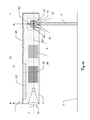
- FIG. 1 is a generic hand-held distance measuring device 1 for measuring distances in external view shown. It has a housing in which the necessary electronic components are arranged. The housing is designed so that the distance measuring device 1 held in the hand and can also be created defined or defined at a point to be measured. On the housing corresponding abutment edges or fold-out or attachable stop elements may be appropriate for this purpose, as shown for example in the WO 02/50564 to be discribed.
- the distance measuring device 1 includes on its front side a laser rangefinder 20 with a laser emitting unit 21 and a laser receiving unit 22, which have optical openings in the housing. On the top of the device are a display device 23 in the form of a display and input means 24 in the form of a keypad. In addition, a camera (not shown here) for taking pictures in the direction of the emission direction can be provided.
- the laser emitting unit 21 emits a laser beam 7 to a measuring point 10 on a wall.
- the wall has a naturally rough surface, from which optical rays are scattered.
- a part of the scattered reflected rays 7 ' is collected by the laser receiving unit 22, detected and converted into an electric signal.
- the signal is evaluated in a manner known per se for determining the digital value of the distance 13 from an electronic circuit.
- phase or transit time measurement can be used.
- the extension between the laser receiving unit 22 and a measuring stop is taken into account.
- the digitally determined value of the measured distance 13 - from here, for example, 3.032 meters - is then made available on the display 23 to a user.
- FIG. 2 shows the inventive hand-held distance measuring device 1, which emits a laser beam 7 in the emission direction 9 to a measuring point 10. Also shown are the axes of rotation orthogonal to the emission direction 9: the transverse axis 18 and the standing axis 19.
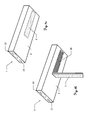
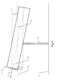
- FIGS. 3a and 3b show an embodiment of the hand-held distance measuring device 1 according to the invention with a laser emitting unit 21 and a laser receiving unit 22 in a view obliquely from below.
- a Referenz réelles unit 3 is integrated in the form of a fold-out pin.
- FIG. 3a is the Referenz réelles discipline 3 folded so that it is flush with the surface of the housing 4.
- FIG. 3b the Referenz réelles staff 3 is unfolded and occupies approximately a right angle to the housing 4 a. In this position, the Referenz réelles accommodate 3 with respect to the distance measuring device 1 in three dimensions is both rotatable and tiltable and tiltable.
- the lower end of the referencing support 3 can be set to a point of a reference object 2 (reference point) or fixed in a receptacle provided for this purpose, for example, a stand 8 or a tripod.
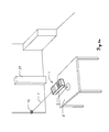
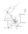
- FIGS. 4a and 4b is shown how the distance measuring device 1 by means of the Referenzierungs bore 3 with a - at least for the period of one or more measurements - relative to a reference coordinate system fixed reference object 2 can be connected.
- the Referenzianss tone 3 of the distance measuring device 1 is connected to a stand 8, which ensures a firm footing on a surface of a reference object 2, for example a table top.
- the distance measuring device 1 and the Referenz réellesmony 3 then do not have to be constantly held in the hand, and the measurement accuracy is increased.
- the reference object 2 is a three-legged tripod.
- the Referenzianss result 3 of the distance measuring device 1 is connected directly to the tripod.
- the Connection of the Referenz réelles compound 3 with the base 8 or the reference object 2 can be done in particular by a screw or plug connection.
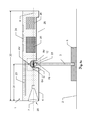
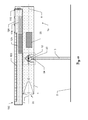
- FIG. 5a illustrates a longitudinal section through a first preferred embodiment of the hand-held distance measuring device 1 according to the invention.
- the reference support 3 is folded out about a hinge 29 into the referencing position and connected to a stand 8 which stands on a reference point on the surface of a reference object 2.
- the distance measuring device 1 includes a laser rangefinder 20 with a laser beam 7 emitted in the emission direction 9. Furthermore, a display 23, input means 24 and the recess 28 for the referencing support 3 in the housing 4 are shown.
- an angle determination unit 33, an evaluation component 25 and an inertial sensor 26 are shown.
- Two angle encoders 5H, 5V with associated sensors 6H, 6V are provided as components of the angle determination unit 33 at three-dimensionally rotatable about the pivot point 12 of the Referenz réelles solicit 3 with the distance measuring device, the horizontal and vertical angles between two spatial orientations of the distance measuring device 1 relative to Referenz réelles note can capture.
- the axis of the emission direction 9 passes through the pivot point 12, which is located in a known partial distance 31 of the known total length 30 of the distance measuring device 1 from the front side. This allows in particular simpler arithmetic operations.
- the distance measuring device 1 contains an energy source (not shown), in particular a battery or a rechargeable battery, provides the electrical energy for the electrically operated components of the distance measuring device 1.
- a digitally present distance value can be stored, further processed or transmitted by the evaluation component 25 of the device-as is customary today with optically measured distances-and displayed on the display 24 to a user.
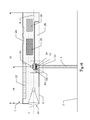
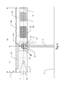
- FIGS. 5b . 5c and 5d show three further preferred embodiments of the inventive hand-held distance measuring device 1.
- the Referenzianss are designed removable and is connected via the connecting element 34 with the angle determination unit 33, in particular by a screw or plug connection.
- the housing 4 has an opening through which the Referenz réelles discipline 3 can be inserted into the recess 28 after use.
- FIG. 5d a fourth embodiment of the hand-held distance measuring device 1 according to the invention is shown.
- the angle determination unit 33 is here attached to the rear area of the device.
- the connecting element 34 is a Referenzierungs house 3 plugged or screwed, which is stored separately from the remainder of the distance measuring device 1 in the detached state or on a on an outer side of the housing 4 optionally provided holder (not shown) can be fastened.
- FIG. 5e shows a side view of an inventive distance measuring device 1.
- dashed lines is a first orientation of the housing with a first Emission direction 9 shown, with solid lines, a second orientation with a second emission direction 9 '.
- the orientation of the Referenz ists instrument 3 remains unchanged in a change in alignment of the housing, so that an angle - shown here the vertical tilt angle ⁇ - between the two orientations of an angle determination unit of the distance measuring device 1 can be detected.
- FIGS. 6a and 6b a method is illustrated how the distance measuring device 1 according to the invention can be used to determine a distance 12 between two remote measuring points, for example if an obstacle 27 prevents direct measurement from point 10 to point 11.
- FIG. 6a an exemplary embodiment of the inventive hand-held distance measuring device 1 when measuring the distance to the first measuring point 10 is shown.
- the distance measuring device 1 is connected via the Referenzierungs house 3 at a reference point with a - at least for the period of the measurement sequence - relative to a reference coordinate system fixed reference object 2 (shown here as a table) and emits a laser beam 7 in the direction of the first measuring point 10.
- FIG. 6b the hand-held distance measuring device 1 according to the invention is shown when measuring at the second measuring point 11.
- the position of the Referenzierungs bon 3 remains unchanged at the reference point on the reference object 2 with respect to the first measurement, it is only the housing 4 is realigned around the pivot point 12 around.
- a protractor determines a horizontal and / or vertical angle ⁇ between the first emission direction 9 and the second emission direction 9 '. From the determined angles and the measured distances 13, 14 between the pivot point 12 and the measuring points 10, 11, the evaluation unit 25 calculates the distance 15 between the measuring points 10, 11.
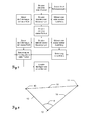
- FIG. 7 is a flow chart that illustrates the steps in the FIGS. 6a and 6b illustrated measuring method that run after the process start.
- the user selects the corresponding method via the input means 24 and fixes the referencing support 3 on a reference object 2 at the reference point.
- the user aims with the laser beam 7 of the distance measuring device 1 to the first measuring point 10 and initiates the measuring process via the input means 24.
- the evaluation unit determines and stores the values for the distance and the alignment determined by laser range finders 20, angle sensors 6H, 6V and inclination sensors.
- the user pivots the housing 4 of the distance measuring device 1 (without loosening the fixation of the Referenztechniks lab 3 on the reference point) and aims at the second measuring point 11 at.
- the evaluation unit 25 determines and stores a further distance and alignment. From the values for the orientation of the housing 4, the evaluation unit 25 first calculates an angle ⁇ . This angle and the measured distances are used to calculate the distance between the two measurement points. The result is displayed to the user on a display.
- FIG. 8 shows the trigonometric principles of the inventive method.
- the length of a line 15 can be calculated by means of the known distances 13, 14 from any room point 12 to the end points 10, 11 of the line 15 and the angle ⁇ between the directions from the room point 12 to the end points 10, 11.
- the cosine set can be used for this purpose.
- FIGS. 9a to 9e Exemplary measuring methods are shown, which can be carried out with the hand-held distance measuring device 1 according to the invention.
- FIG. 9a illustrates a method for determining a span, ie, a distance between two points, from a remote location.
- a span ie, a distance between two points
- the distance measuring device 1 is pivoted to aim at a second measuring point 11 whose distance 15 from the first measuring point 10 is to be determined.
- a mode of continuous measurement (“tracking mode") is possible, in which for each target point the distance 15 to the first measuring point 11 is displayed on the display.
- FIGS. 9b and 9c illustrate a method for easily determining a vertical distance of a measuring point to a horizontal plane 17, which is defined by a first measuring point 10.
- a reference height eg a point on a wall
- the distance measuring device 1 is aligned, for example, to a point on another wall and triggered the measurement.
- the display displays a relative height of the laser spot to the horizontal plane 17 defined by the reference height.
- a second measuring point can be marked at the same height, or a desired other height.
- a mode of continuous measurement (“tracking mode") is also possible in which a reaching of the reference altitude or a different altitude set by the user is automatically displayed or the distance of a current measuring point from this altitude is continuously displayed.
- the Figures 9d and 9e illustrate another with the inventive hand-held distance measuring device executable method.
- the determination of an orthogonal distance of a measuring point to a straight line which is defined by two first measuring points 10, 11, is possible.
- the user first targets a measuring point 10 and measures its distance and the current orientation of the distance measuring device 1. Subsequently, the user repeats this with a second measuring point 11. This defines a straight line through the two measuring points 10, 11. All measurements are treated as horizontal projection.
- the user aims at a third measuring point; the display shows the distance of the point to the straight line. The user can now move the laser spot until a desired distance is found. In particular, a parallel 16 to the line can be determined with this function.
- FIG. 10 is a further embodiment of the inventive hand-held distance measuring device shown.
- the device is configured as a placement module 1a, which is configured for mechanical connection to a hand-held small computer, for example a so-called smartphone or tablet computer.
- a smartphone 100 Shown here is a smartphone 100, which is placed on the hand-holdable Aufsetzmodul 1a, with a standardized data interface 110, for example configured as a USB interface, a data exchange between placement module 1a and smartphone 100 is possible.
- the placement module 1a has neither a display nor input means; their tasks are instead replaced by display 123 and input means 124 of the smartphone 100 provided.
- An inclination sensor can also be dispensed with in the placement module 1a since the illustrated smartphone 100 has an inclination sensor 126.
- the placement module 1a includes a laser rangefinder 20 with a laser beam 7 emitted in the emission direction 9 and an angle determination unit 33 at the pivot point 12. The axis of the emission direction 9 preferably runs through the pivot point 12.
Abstract
Description
Die vorliegende Erfindung betrifft ein handhaltbares Entfernungsmessgerät mit einer Distanzmesseinheit und einer Winkelbestimmungseinheit zur Bestimmung von Raumwinkeln in Relation zu einem Referenzkoordinatensystem, mittels welchem dreidimensionale Koordinaten von Raumpunkten bestimmt und angezeigt werden können.The present invention relates to a hand-held distance measuring device with a distance measuring unit and an angle determination unit for determining solid angles in relation to a reference coordinate system, by means of which three-dimensional coordinates of spatial points can be determined and displayed.
Ein erfindungsgemäßes handhaltbares Entfernungsmessgerät beinhaltet zu diesem Zweck eine insbesondere ausklappbare Referenzierungsstütze, mit welcher Winkel und Ausrichtungsänderungen des Entfernungsmessgerätes relativ zu einem zum Referenzkoordinatensystem feststehenden externen Referenzobjekt bestimmt werden können. Die räumliche Ausrichtung des Entfernungsmessgerätes gegenüber dem Referenzobjekt ist insbesondere über Winkelmesser erfassbar. Zusätzlich können Neigungssensoren zur Bestimmung der Ausrichtung bezüglich des Schwerefeld-Vektors der Erde vorgesehen sein.A hand-held distance measuring device according to the invention comprises for this purpose a particularly foldable reference support with which angles and orientation changes of the distance measuring device relative to an external reference object fixed to the reference coordinate system can be determined. The spatial orientation of the distance measuring device relative to the reference object can be detected in particular by protractors. In addition, tilt sensors may be provided to determine the orientation with respect to the earth's gravity field vector.
In vielen Anwendungen werden Verfahren und Systeme zur Entfernungsmessung verwendet. Beispiele hierfür sind ausgesprochen präzise Vermessungen in geodätischen Applikationen, aber auch Messaufgaben im Bereich der Bauinstallation oder für industrielle Prozesssteuerungen.In many applications, methods and systems for distance measurement are used. Examples include extremely precise measurements in geodetic applications, but also measuring tasks in the field of building installation or for industrial process control.
Für diese Aufgaben werden stationäre, bewegbare oder auch handhaltbare Entfernungsmessgeräte eingesetzt, welche eine optische Entfernungsmessung zu einem ausgewählten Messpunkt ausführen. Zumeist wird hierbei ein Laserstrahl emittiert und nach Reflektion am Ziel wieder empfangen und ausgewertet. Zur Bestimmung der Entfernung stehen dabei verschiedene Messprinzipien zur Verfügung, wie z.B. Phasen- oder Laufzeitmessung.For these tasks stationary, movable or hand-held distance measuring devices are used, which perform an optical distance measurement to a selected measuring point. In most cases, a laser beam is emitted and received and evaluated again after reflection at the target. To determine the distance are Various measuring principles available, such as phase or transit time measurement.
Insbesondere im Bereich der Bauinstallation oder Bauabnahme werden tragbare und in der Hand zu haltende Geräte verwendet, welche bezüglich einer zu vermessenden Struktur angelegt werden und dann eine Entfernungsmessung zu einer Oberfläche durchführen. Ein für solche Anwendungen geeignetes und typisches handhaltbares Entfernungsmessgerät wird beispielsweise in der
Da für die meisten Anwendungen ein auf der anzumessenden Oberfläche sichtbarer Messpunkt vorteilhaft ist, werden zumeist rote Laser als Strahlungsquellen für die Entfernungsmessung verwendet. Mit Entfernungsmessern des Stands der Technik sind so bei grosser Handhabungsfreundlichkeit Genauigkeiten bis in den Millimeterbereich erzielbar. Mit derzeit erhältlichen handhaltbaren Entfernungsmessgeräten können Messungen von einem Punkt zu einem anderen Punkt durchgeführt werden, zu dem eine Sichtverbindung besteht. Wenn das Ziel verdeckt ist, können mittels eines Neigungssensors auch Horizontalmasse ermittelt werden.Since for most applications a measuring point visible on the surface to be measured is advantageous, red lasers are mostly used as radiation sources for the distance measurement. With distance meters of the prior art accuracies up to the millimeter range can be achieved with great ease of handling. With currently available hand-held range finders, measurements can be made from one point to another point to which there is line of sight. If the target is obscured, horizontal mass can also be determined by means of an inclination sensor.
Eine Möglichkeit zur Bestimmung einer Entfernung zwischen zwei Punkten, die auch anwendbar ist, wenn zwischen den Punkten keine Sichtverbindung besteht, ist die Berechnung mittels Trigonometrie. Dies ist bereits aus bodengestützten Vermessungsgeräten, wie Theodoliten oder Totalstationen, hinlänglich bekannt.One way of determining a distance between two points, which is also applicable when there is no line of sight between the points, is by trigonometry calculation. This is already well known from ground-based surveying equipment, such as the theodolites or total stations.
Zur trigonometrischen Ermittlung einer Entfernung a zwischen zwei Raumpunkten B und C genügt es, die Entfernung zu diesen zwei Punkten von einem dritten Punkt A zu kennen, und den Winkel α an Punkt A zwischen den Seiten b und c in Richtung der Punkte B und C. Dann kann mittels des Kosinussatzes die Länge von a errechnet werden: 
Mit einem herkömmlichen handhaltbaren Entfernungsmessgerät des Standes der Technik ist es zwar möglich, die Distanzen b und c zu den Raumpunkten B und C exakt zu messen, es fehlt aber in aller Regel an einer Funktion zur genauen und zuverlässigen Bestimmung des Winkels α. Heute verfügbare Beschleunigungssensoren können für Zwecke der Entfernungsberechnung keinen ausreichend verlässlichen Wert für α liefern, und Kompasse sind insbesondere in Innenräumen von Gebäuden störungsanfällig; allenfalls Winkel in der Vertikalen können mittels Neigungssensoren mit ausreichender Genauigkeit und Verlässlichkeit ermittelt werden.Although it is possible with a conventional hand-held distance measuring device of the prior art to measure the distances b and c to the spatial points B and C exactly, as a rule it lacks a function for the accurate and reliable determination of the angle α. Acceleration sensors available today can not provide a sufficiently reliable value for α for purposes of range calculation, and compasses are susceptible to failure particularly indoors; at most angles in the vertical can be determined by inclination sensors with sufficient accuracy and reliability.
Im Stand der Technik sind verschiedene Lösungen mit handhaltbaren Entfernungsmessgeräten mit Laserentfernungsmessern beschrieben, mittels derer zwei Punkte gleichzeitig angezielt werden können, wobei ein Winkel zwischen den Emissionsrichtungen der beiden Laser bestimmt werden kann.The prior art describes various solutions with hand-held distance measuring devices with laser rangefinders, by means of which two points can be aimed simultaneously, wherein an angle between the emission directions of the two lasers can be determined.
In den beiden Dokumenten
In der
Nachteilig bei allen diesen Lösungen ist insbesondere der erhöhte Materialaufwand, da jeweils zwei Lasermessmodule oder sogar zwei komplette Entfernungsmessgeräte zur Messung vonnöten sind.A disadvantage of all these solutions is in particular the increased cost of materials, since in each case two laser measuring modules or even two complete distance measuring devices are required for the measurement.
Es ist daher eine Aufgabe der vorliegenden Erfindung, ein handhaltbares Entfernungsmessgerät bereitzustellen, das eine Bestimmung dreidimensionaler Koordinaten von mindestens zwei Raumpunkten innerhalb eines gemeinsamen Referenzkoordinatensystems erlaubt.It is therefore an object of the present invention to provide a hand-held distance measuring device which allows a determination of three-dimensional coordinates of at least two spatial points within a common reference coordinate system.
Eine weitere Aufgabe der Erfindung ist es, ein solches Entfernungsmessgerät mit einem geringeren konstruktiven Aufwand bereitzustellen, und insbesondere ohne das Erfordernis, das Entfernungsmessgerät in eine separate Winkelmessvorrichtung einzuspannen.A further object of the invention is to provide such a distance measuring device with a lower design effort, and in particular without the need to clamp the distance measuring device in a separate angle measuring device.
Es ist ausserdem eine besondere Aufgabe der Erfindung, ein solches handhaltbares Entfernungsmessgerät bereitzustellen, das mit nur einem einzigen Laserentfernungsmesser ausgestattet ist.It is also a particular object of the invention to provide such a hand-held rangefinder that is equipped with only a single laser rangefinder.
Mindestens eine dieser Aufgaben wird durch die Verwirklichung der kennzeichnenden Merkmale der unabhängigen Ansprüche gelöst. Vorteilhafte Ausgestaltungen der Erfindung finden sich dabei in den jeweils abhängigen Ansprüchen.At least one of these objects is achieved by the realization of the characterizing features of the independent claims. Advantageous embodiments of the invention can be found in the respective dependent claims.
Das handhaltbare Entfernungsmessgerät der vorliegenden Erfindung ist in der Lage, Raumwinkel in einem Referenzkoordinatensystem sowohl in der Vertikalen als auch in der Horizontalen exakt zu erfassen, wodurch mittels einfacher trigonometrischer Berechnung die Ermittelung einer genauen Entfernung zwischen zwei nacheinander vermessenen Raumpunkten ermöglicht wird.The handheld range finder of the present invention is capable of accurately detecting solid angles in a reference coordinate system in both the vertical and horizontal directions, thereby providing a simpler way of detecting solid angles Trigonometric calculation, the determination of a precise distance between two consecutively measured spatial points is made possible.
Dazu wird das Entfernungsmessgerät erfindungsgemäss über eine - vorzugsweise ausklappbare - Referenzierungsstütze mit einem - zumindest während des Messvorganges - relativ zum Referenzkoordinatensystem feststehenden Referenzobjekt verbunden, um Änderungen der räumlichen Ausrichtung des Entfernungsmessgerätes in Relation zu dem Referenzobjekt zu erfassen. Dieses Referenzobjekt kann beispielsweise eine Tischplatte, ein Stativ oder auch ein Teil der Erdoberfläche, bzw. der Fussboden, sein.For this purpose, the distance measuring device according to the invention via a - preferably folding - Referenzierungsstütze with a - at least during the measurement process - relative to the reference coordinate fixed reference object to detect changes in the spatial orientation of the distance measuring device in relation to the reference object. This reference object may for example be a table top, a tripod or even a part of the earth's surface, or the floor.
Die Referenzierungsstütze ist mit einem Ende drehbar am Entfernungsmessgerät angebracht, vorzugsweise dreidimensional drehbar. Eine erfindungsgemässe Referenzierungsstütze kann beispielsweise aus Kunststoff oder Leichtmetall bestehen und in Form eines aus dem Entfernungsmessgerät nach unten ausklappbaren Stiftes vorliegen.The Referenzierungsstütze is rotatably mounted with one end on the distance measuring device, preferably three-dimensionally rotatable. A reference support according to the invention can be made, for example, of plastic or light metal and can be in the form of a pen which can be folded downwards from the distance measuring device.
Dieser Stift kann am unteren Ende einen Standfuss aufweisen oder Mittel zum Befestigen an einem Standfuss, einem Sockel oder einem Stativ. Zum besseren Fixieren der Referenzierungsstütze auf einer glatten Oberfläche, wie zum Beispiel einer Tischplatte, kann die Unterseite optional gummiert oder mit einem Saugnapf ausgestattet sein.This pin may have a base at the bottom or means for attaching to a base, pedestal or tripod. To better fix the Referenzierungsstütze on a smooth surface, such as a table top, the bottom can optionally be rubberized or equipped with a suction cup.
Die Referenzierungsstütze kann alternativ auch teleskopartig ausziehbar gestaltet sein, oder in Aufnahmemittel des Entfernungsmessgerätes einschraub- oder einsteckbar.The Referenzierungsstütze may alternatively be designed telescopically extendable, or in receiving means of the distance measuring device screwed or plugged.
Es ist auch möglich, dass die Referenzierungsstütze zum Messen nicht auf eine Oberfläche gestellt wird, sondern von einem Benutzer während der Messungen in der einen Hand gehalten wird, während die andere Hand das Entfernungsmessgerät ausrichtet, sofern die die Referenzierungsstütze haltende Hand zwischen den Messungen nicht bewegt wird. Dabei kann die Genauigkeit der Messungen allerdings durch natürliche Körperbewegungen wie Zittern oder das Heben und Senken des Brustkorbs durch Atmen beeinträchtigt werden.It is also possible that the Referenzierungsstütze is not placed on a surface for measuring, but by a user during the measurements in one hand while the other hand is aligning the range finder unless the hand holding the referencing support is moved between measurements. However, the accuracy of the measurements may be affected by natural body movements such as tremors or the lifting and lowering of the chest by breathing.
Ein erfindungsgemässes handhaltbares Entfernungsmessgerät beinhaltet eine Funktion zur Erfassung eines Punktes im Raum, mindestens durch Messung der Distanz zwischen dem Entfernungsmessgerät und dem zu messenden Objekt mit einem sichtbaren Laserstrahl. Die Lage des dreidimensional zu erfassenden Punktes wird, beispielsweise durch Winkelsensoren und/oder Neigungssensoren, im Entfernungsmessgerät bestimmt.An inventive hand-held distance measuring device includes a function for detecting a point in space, at least by measuring the distance between the distance measuring device and the object to be measured with a visible laser beam. The position of the point to be detected three-dimensionally is determined in the distance measuring device, for example by angle sensors and / or inclination sensors.
Das erfindungsgemässe handhaltbare Entfernungsmessgerät enthält ein Distanzmessmodul zur Messung der Entfernung zu auf Oberflächen gelegenen Raumpunkten. Das Distanzmessmodul ist bevorzugt ein Laserdistanzmesser, der einen, insbesondere sichtbaren, Laserstrahl in Richtung eines zu vermessenden Punktes aussendet. Dazu weist das Distanzmessmodul eine, beispielsweise in das Gehäuse des Entfernungsmessgerätes eingelassene, Optik auf. Zum optischen Messen der Distanz zu einer Oberfläche werden von der Vorrichtung über die Optik modulierte optische Sendestrahlen in Form eines Strahlenbündels gegen die Oberfläche ausgesendet. Ein Teil der von der Oberfläche reflektierten Strahlen der Sendestrahlen wird von der Optik wieder eingesammelt und für ein Bestimmen von Distanzen elektronisch ausgewertet.The hand-held distance measuring device according to the invention contains a distance measuring module for measuring the distance to spatial points located on surfaces. The distance measuring module is preferably a laser distance meter, which emits a, in particular visible, laser beam in the direction of a point to be measured. For this purpose, the distance measuring module has a, for example, in the housing of the distance measuring device embedded optics. For optically measuring the distance to a surface, optically transmitted beams modulated by the device via the optics are emitted in the form of a beam against the surface. Part of the rays of the transmitted beams reflected from the surface are collected again by the optics and evaluated electronically for determining distances.
Das erfindungsgemässe handhaltbare Entfernungsmessgerät enthält ausserdem bevorzugt einen Neigungssensor zur Erfassung mindestens einer Längsneigung des Gerätes. Die Bestimmung der Lage des handhaltbaren Entfernungsmessgeräts im Raum kann in Bezug auf das Referenzkoordinatensystem mittels Neigungssensor vollautomatisch ermittelt werden. Alle Lagefehler des handhaltbaren Entfernungsmessgerätes können dadurch vollautomatisch kompensiert werden.The hand-held distance measuring device according to the invention also preferably contains a tilt sensor for Detection of at least one longitudinal inclination of the device. The determination of the position of the hand-held distance measuring device in space can be determined fully automatically with respect to the reference coordinate system by means of an inclination sensor. All positional errors of the hand-held distance measuring device can thereby be compensated fully automatically.
Durch die Integration zusätzlicher Komponenten zum Messen von Winkeln (Winkelbestimmungseinheit) ist das erfindungsgemässe Entfernungsmessgerät in der Lage, ausser Distanzen auch horizontale und vertikale Raumwinkel, eine Querneigung des Laserdistanzmessers bzw. der Horizontalachse des Entfernungsmessgerätes, eine Längsneigung des Laserdistanzmessers sowie eine Längsneigung der Horizontalachse zu messen. Mittels dieser gemessenen Werte können von einer Auswerteeinheit korrigierte dreidimensionale Koordinaten ermittelt werden, die unter anderem zur Berechnung von Horizontal- und Schrägdistanzen zwischen Raumpunkten genutzt werden können.By integrating additional components for measuring angles (angle determination unit), the distance measuring device according to the invention is able to measure, in addition to distances, horizontal and vertical solid angles, a transverse inclination of the laser distance meter or the horizontal axis of the distance measuring device, a longitudinal inclination of the laser distance meter and a longitudinal inclination of the horizontal axis , By means of these measured values, three-dimensional coordinates corrected by an evaluation unit can be determined, which can be used inter alia for calculating horizontal and oblique distances between spatial points.
Diese zusätzlichen, zur Winkelbestimmung geeigneten Komponenten der Winkelbestimmungseinheit umfassen erfindungsgemäss entweder einen Neigungssensor und einen Winkelencoder, der insbesondere dazu ausgebildet ist, horizontale Winkel zu erfassen, oder zwei Winkelencoder, davon einen vertikale Winkel erfassenden und einen horizontale Winkel erfassenden Winkelencoder. Optional können zusätzlich ein Zwei-Achsen-Neigungssensor auf der Horizontalachse, ein Kompass und/oder ein Gyroskop enthalten sein.According to the invention, these additional components of the angle determination unit which are suitable for determining angles comprise either an inclination sensor and an angle encoder, which is designed in particular to detect horizontal angles, or two angle encoders, including an angle detector detecting a vertical angle and detecting a horizontal angle. Optionally, a two-axis inclination sensor on the horizontal axis, a compass and / or a gyroscope may additionally be included.
Eine erste Ausrichtung des Systems kann optional anhand eines Kompasses oder eines GPS-Sensors erfolgen. Zum erfindungsgemässen Messen von Winkeln sind sowohl inkrementell als auch absolut arbeitende Winkelencoder geeignet, also Inkrementalgeber oder Absolutwertgeber.An initial alignment of the system can optionally be done using a compass or a GPS sensor. To measure angles in accordance with the invention are both incremental as well as absolutely working angle encoders suitable, ie incremental encoders or absolute encoders.
In einer bevorzugten Ausführungsform beinhaltet das erfindungsgemässe handhaltbare Entfernungsmessgerät mindestens einen Winkelencoder. Der oder die Winkelencoder sind in der Winkelbestimmungseinheit in einem integrierten mechanischen System angeordnet.In a preferred embodiment, the hand-held distance measuring device according to the invention comprises at least one angle encoder. The angle encoder (s) are arranged in the angle determination unit in an integrated mechanical system.
Insbesondere ist die Winkelbestimmungseinheit derart angeordnet, dass an der Referenzierungsstütze, bzw. vorzugsweise im Innern des Entfernungsmessgerät an einer Befestigung für die Referenzierungsstütze mindestens ein Winkelencoder vorgesehen ist, der eine relative Ausrichtung des Gehäuses des Entfernungsmessgerätes in Bezug auf die Referenzierungsstütze und/oder einen Raumwinkel zwischen zwei Ausrichtungen des Entfernungsmessgerätes erfassen kann, mindestens in der Horizontalebene, vorzugsweise auch vertikal. Eine vertikale Ausrichtung kann alternativ auch durch einen Neigungssensor ermittelt werden. Dieser Neigungssensor kann auf der horizontalen Rotationsachse angebracht werden, um absolute Höhenreferenz in jeder Lage des Entfernungsmessgeräts zu bestimmen. Das Entfernungsmessgerät kann durch den integrierten Neigungssensor Höhen und Koordinaten absolut anzeigen.In particular, the angle determination unit is arranged such that at least one angle encoder is provided on the referencing support, or preferably in the interior of the distance measuring device on a mounting for the Referenzierungsstütze, the relative orientation of the housing of the distance measuring device with respect to the Referenzierungsstütze and / or a solid angle between can detect two orientations of the distance measuring device, at least in the horizontal plane, preferably also vertically. A vertical orientation can alternatively also be determined by an inclination sensor. This tilt sensor can be mounted on the horizontal axis of rotation to determine absolute height reference in each position of the rangefinder. The rangefinder can display altitudes and coordinates absolutely through the integrated tilt sensor.
Vorzugsweise kann die Referenzierungsstütze des Entfernungsmessgerätes über Sensoren zum Erfassen und Kompensieren von Messfehlern verfügen. Insbesondere in dem Falle, dass die Referenzierungsstütze vom Benutzer mit der Hand auf einen Referenzpunkt des Referenzobjekts gehalten wird, kann ein Wackeln der Referenzierungsstütze oder des gesamten Entfernungsmessgerätes auftreten. Ein Wackeln während eines Messvorganges oder zwischen zwei oder mehr Messvorgängen kann zu Messfehlern führen. Darum kann das Entfernungsmessgerät bevorzugt über zusätzliche Neigungssensoren in der Referenzierungsstütze oder an der Verbindung mit dem Gehäuse, beispielsweise auf der Winkelbestimmungseinheit, verfügen, die eine Bestimmung der räumlichen Ausrichtung der Referenzierungsstütze ermöglicht. Die Ausrichtung bzw. Ausrichtungsänderung der Stütze kann dann zur dynamischen Bestimmung der Lage des Entfernungsmessgerätes relativ zum Referenzpunkt verwendet und bei der Berechnung von Raumkoordinaten berücksichtigt werden.The reference support of the distance measuring device may preferably have sensors for detecting and compensating for measurement errors. In particular, in the event that the Referenzierungsstütze is held by the user by hand on a reference point of the reference object, a wobble of the Referenzungsstütze or the entire rangefinder may occur. A wobble during a measurement or between two or more Measuring operations can lead to measurement errors. Therefore, the rangefinder may preferably have additional inclination sensors in the referencing support or at the connection to the housing, for example on the angle determination unit, which allows a determination of the spatial orientation of the Referenzierungsstütze. The orientation of the support can then be used to dynamically determine the position of the rangefinder relative to the reference point and to be taken into account in the calculation of spatial coordinates.
Das erfindungsgemässe handhaltbare Entfernungsmessgerät kann Entfernungen zwischen zwei Punkten messen, ohne dass ein Referenzpunkt direkt zugänglich sein muss. Das Entfernungsmessgerät kann so das Spannmass zwischen zwei beliebigen mit dem Laserpunkt anzielbaren Punkten darstellen.The hand-held distance measuring device according to the invention can measure distances between two points without a reference point having to be directly accessible. The distance measuring device can thus represent the clamping distance between any two points which can be targeted by the laser point.
Das erfindungsgemässe handhaltbare Entfernungsmessgerät kann vorgegebene Koordinaten relativ zum ersten Messpunkt abstecken und dem Benutzer signalisieren. Ebenso kann von jedem beliebigen Punkt die Lotposition angezeigt werden.The hand-held distance measuring device according to the invention can stake out predetermined coordinates relative to the first measuring point and signal the user. Likewise, the plumb position can be displayed from any point.
Flächen von im Raum liegenden geometrischen Formen, die durch mindestens drei Messpunkte definiert werden, können automatisch berechnet werden. In ein aufgenommenes Mess-Image können automatisch geometrische Formen eingepasst werden, und deren Abmasse ermittelt werden. Mit dem aufgenommen Mess-Image können die Messpunkte an die gewünschte Position geschoben werden. Die Messkoordinaten werden dabei automatisch extrapoliert.Areas of geometric shapes in space defined by at least three measurement points can be automatically calculated. In a recorded measurement image, geometric shapes can be automatically fitted, and their dimensions are determined. With the recorded measurement image, the measuring points can be moved to the desired position. The measuring coordinates are automatically extrapolated.
In einer weiteren Ausführungsform weist das erfindungsgemässe Entfernungsmessgerät eine Anzielhilfe, beispielsweise in Form eines Griffes, oder Mittel zur Aufnahme einer solchen Anzielhilfe auf. Eine solche Anzielhilfe, die beispielsweise am dem Laserentfernungsmesser gegenüberliegenden Ende des Entfernungsmessgerätes ausgeklappt oder ausgezogen bzw. angeschraubt oder anderweitig angebracht werden kann, erleichtert das genaue Anzielen eines Messpunktes.In a further embodiment, the distance measuring device according to the invention has a targeting aid, for example in the form of a handle, or means for receiving such a targeting aid. Such a targeting aid, which, for example, can be unfolded or pulled out or screwed on or otherwise attached to the end of the distance measuring device opposite the laser rangefinder, facilitates accurate targeting of a measuring point.
In einer alternativen Ausführungsform ist das erfindungsgemässe Entfernungsmessgerät als ein Aufsetzmodul für einen handhaltbaren Kleincomputer, beispielsweise einen Tablett-Computer oder ein Smartphone, ausgestaltet. Dabei kann im Aufsetzmodul vorzugsweise auf Display, Eingabemittel und Neigungssensoren verzichtet werden, da diese in der Regel von heutigen Tablett-Computern und Smartphones bereitgestellt werden. Ebenso können digital vorliegende Entfernungswerte von einer Auswertekomponente des angeschlossenen Gerätes gespeichert und weiterverarbeitet werden. Über eine drahtlose Verbindung, beispielsweise mittels Bluetooth oder WLAN, bzw. über eine standardisierte Datenschnittstelle, beispielsweise ausgestaltet als USB-Schnittstelle, können Daten zwischen dem als Aufsetzmodul ausgestaltetem Entfernungsmessgerät und dem Kleincomputer ausgetauscht werden. Ein solches Aufsetzmodul kann entweder zur Aufnahme eines Kleincomputers mit genau definierten Ausmassen ausgestaltet sein, zum Beispiel eines bestimmten Typs eines Smartphones, oder für Geräte verschiedener Grössen und/oder Typen. Die Bedienung des Entfernungsmessgerätes und die Darstellung der Ergebnisse erfolgt über das an das Aufsetzmodul angeschlossene Gerät. Eine Software zur Ausführung der Entfernungsmessung mittels dieser Ausführungsform kann vorzugsweise von dem Aufsetzmodul auf den Kleincomputer übertragbar sein oder aber anderweitig installierbar sein, beispielsweise durch kostenloses oder gebührenpflichtiges Herunterladen aus dem Internet.In an alternative embodiment, the distance measuring device according to the invention is configured as a placement module for a handheld small computer, for example a tablet computer or a smartphone. In the placement module, display, input means and inclination sensors can preferably be dispensed with, since these are generally provided by today's tablet computers and smartphones. Likewise, digitally present distance values can be stored and further processed by an evaluation component of the connected device. Via a wireless connection, for example by means of Bluetooth or WLAN, or via a standardized data interface, configured for example as a USB interface, data can be exchanged between the distance measuring device designed as a placement module and the miniature computer. Such a placement module can either be designed to hold a small computer with well-defined dimensions, for example of a certain type of smartphone, or for devices of different sizes and / or types. The operation of the distance measuring device and the presentation of the results via the device connected to the Aufsetzmodul. A software for performing ranging by means of this embodiment may preferably be transferable from the placement module to the minicomputer or otherwise be installable, for example, by free or paid downloads from the Internet.
Das Aufsetzmodul kann eine Kamera aufweisen, die Bilder in Richtung der Emissionsrichtung des Laserstrahls aufnimmt, die einem Benutzer über das Display des angeschlossenen Gerätes anzeigbar sind. Verfügt das anschliessbare Gerät über eine Kamera, die an der dem Aufsetzmodul zugewandten Seite angebracht ist, so kann das Aufsetzmodul vorteilhaft auch über Umlenkmittel, zum Beispiel einen Spiegel, verfügen, die das Kamerabild in Richtung der Emissionsachse des Laserstrahls umlenken.The placement module can have a camera that records images in the direction of the emission direction of the laser beam, which can be displayed to a user via the display of the connected device. If the connectable device has a camera which is attached to the side facing the placement module, the placement module can advantageously also have deflection means, for example a mirror, which deflect the camera image in the direction of the emission axis of the laser beam.
Das erfindungsgemässe handhaltbare Entfernungsmessgerät und das erfindungsgemässe Messverfahren werden nachfolgend anhand von in den Zeichnungen schematisch dargestellten konkreten Ausführungsbeispielen rein beispielhaft näher beschrieben, wobei auch auf weitere Vorteile der Erfindung eingegangen wird. Im Einzelnen zeigen:
- Fig. 1
- ein erfindungsgemässes handhaltbares Entfernungsmessgerät mit einem Laserdistanzmesser;
- Fig. 2
- ein erfindungsgemässes handhaltbares Entfernungsmessgerät und die drei Drehachsen des Referenzkoordinatensystems;
- Fig. 3a
- ein erfindungsgemässes handhaltbares Entfernungsmessgerät mit einer eingeklappten Referenzierungsstütze;
- Fig. 3b
- ein erfindungsgemässes handhaltbares Entfernungsmessgerät mit einer ausgeklappten Referenzierungsstütze;
- Fig. 4a
- eine Kombination eines erfindungsgemässen handhaltbaren Entfernungsmessgerätes mit einem Standfuss;
- Fig. 4b
- eine Kombination eines erfindungsgemässen handhaltbaren Entfernungsmessgerätes mit einem Stativ;
- Fig. 4c
- ein erfindungsgemässes handhaltbares Entfernungsmessgerät mit einer Anzielhilfe;
- Fig. 5a
- eine erste beispielhafte Ausführungsform eines erfindungsgemässen handhaltbaren Entfernungsmessgerätes in einer Längsschnittansicht;
- Fig. 5b
- eine zweite beispielhafte Ausführungsform eines erfindungsgemässen handhaltbaren Entfernungsmessgerätes in einer Längsschnittansicht;
- Fig. 5c
- eine dritte beispielhafte Ausführungsform eines erfindungsgemässen handhaltbaren Entfernungsmessgerätes in einer Längsschnittansicht;
- Fig. 5d
- eine vierte beispielhafte Ausführungsform eines erfindungsgemässen handhaltbaren Entfernungsmessgerätes in einer Längsschnittansicht;
- Fig. 5e
- ein erfindungsgemässes handhaltbares Entfernungsmessgerät in einer Seitenansicht mit zwei - bezüglich eines zur Referenzierungsstütze relativen Vertikalwinkels - unterschiedlichen Ausrichtungen des Gehäuses.
- Fig. 6a
- eine beispielhafte Ausführungsform des erfindungsgemässen handhaltbaren Entfernungsmessgerätes beim Messen der Entfernung zu einem ersten Messpunkt;
- Fig. 6b
- eine beispielhafte Ausführungsform des erfindungsgemässen handhaltbaren Entfernungsmessgerätes beim Messen der Entfernung zu einem zweiten Messpunkt;
- Fig. 7
- ein Flussdiagramm zur Vermessung der Entfernung zwischen zwei entfernten Raumpunkten;
- Fig. 8
- ein Diagramm zur Vermessung der Entfernung zwischen zwei entfernten Raumpunkten;
- Fig. 9a-e
- verschiedene Anwendungsbeispiele für das erfindungsgemässe handhaltbare Entfernungsmessgerät; und
- Fig. 10
- eine Ausführung des erfindungsgemässen handhaltbaren Entfernungsmessgerätes als Aufsetzmodul für ein Smartphone in einer Längsschnittansicht.
- Fig. 1
- a hand-held distance measuring device according to the invention with a laser distance meter;
- Fig. 2
- a hand-held distance measuring device according to the invention and the three axes of rotation of the reference coordinate system;
- Fig. 3a
- a hand-held distance measuring device according to the invention with a folded reference support;
- Fig. 3b
- a hand-held distance measuring device according to the invention with an unfolded reference support;
- Fig. 4a
- a combination of an inventive hand-held distance measuring device with a stand;
- Fig. 4b
- a combination of a hand-held distance measuring device according to the invention with a stand;
- Fig. 4c
- a hand-held distance measuring device according to the invention with a targeting aid;
- Fig. 5a
- a first exemplary embodiment of a hand-held distance measuring device according to the invention in a longitudinal sectional view;
- Fig. 5b
- a second exemplary embodiment of a hand-held distance measuring device according to the invention in a longitudinal sectional view;
- Fig. 5c
- a third exemplary embodiment of a hand-held distance measuring device according to the invention in a longitudinal sectional view;
- Fig. 5d
- a fourth exemplary embodiment of a hand-held distance measuring device according to the invention in a longitudinal sectional view;
- Fig. 5e
- a hand-held distance measuring device according to the invention in a side view with two different orientations of the housing relative to a reference angle relative to the vertical angle.
- Fig. 6a
- an exemplary embodiment of the invention hand-held Distance measuring device when measuring the distance to a first measuring point;
- Fig. 6b
- an exemplary embodiment of the hand-held distance measuring device according to the invention when measuring the distance to a second measuring point;
- Fig. 7
- a flow chart for measuring the distance between two distant space points;
- Fig. 8
- a diagram for measuring the distance between two distant space points;
- Fig. 9a-e
- various application examples for the hand-held distance measuring device according to the invention; and
- Fig. 10
- an embodiment of the inventive hand-held distance measuring device as Aufsetzmodul for a smartphone in a longitudinal sectional view.
In
Erfindungsgemäss sendet die Laseraussendeeinheit 21 einen Laserstrahl 7 zu einem Messpunkt 10 auf einer Wand aus. Die Wand weist eine natürlich rauhe Oberfläche auf, von der optische Strahlen streuend reflektiert werden. Ein Teil der gestreut reflektierten Strahlen 7' wird von der Laserempfangseinheit 22 eingesammelt, detektiert und in ein elektrisches Signal umgewandelt. Das Signal wird in an sich bekannter Weise zum Bestimmen des digitalen Werts der Distanz 13 von einer elektronischen Schaltung ausgewertet. Zur Entfernungsermittlung kann z. B. Phasen- oder Laufzeitmessung eingesetzt werden. Dabei wird auch die Erstreckung zwischen der Laserempfangseinheit 22 und einem Messanschlag berücksichtigt. Der durch die Auswertung digital bestimmte Wert der gemessenen Entfernung 13 - von hier beispielsweise 3,032 Metern - wird dann auf dem Display 23 einem Benutzer zur Verfügung gestellt.According to the invention, the
In den
In
In
Ein digital vorliegender Entfernungswert kann - wie bei optisch gemessenen Distanzen heute üblich - von der Auswertekomponente 25 des Gerätes gespeichert, weiterverarbeitet oder übertragen und auf dem Display 24 einem Benutzer angezeigt werden.A digitally present distance value can be stored, further processed or transmitted by the
Die
Um Messfehler durch unbeabsichtigte Ausrichtungsänderungen der Referenzierungsstütze während eines Messvorganges oder zwischen zwei oder mehr Messvorgängen ausschliessen zu können, ist vorzugsweise in oder an der Referenzierungsstütze 3 ein - hier nicht dargestellter - Neigungssensor vorgesehen, der derart ausgestaltet ist, dass er, insbesondere dynamisch fortlaufend, eine aktuelle Ausrichtung der Referenzierungsstütze 3 erfassen kann. Dadurch kann dynamisch die relative Lage des Entfernungsmessgerätes 1 zum Referenzpunkt bestimmt werden. Während der Messungen oder zwischen den Messungen eventuell aufgetretene Ausrichtungsänderungen, beispielsweise durch Wackeln oder Zittern der Hand des Benutzers, werden so erfasst und können in die Berechnung der Winkel und Distanzen einfliessen.In order to rule out measurement errors due to unintentional changes in the orientation of the Referenzierungsstütze during a measurement or between two or more measuring operations, preferably in or on the Referenzierungsstütze 3 - not shown here - inclination sensor is provided which is designed such that it, in particular dynamically continuously, a can detect the current orientation of the
Wird immer eine feste Verbindung zwischen Referenzierungsstütze 3 und Referenzobjekt 2 hergestellt, wie zum Beispiel bei der Verwendung der in den
In
In
In
In den
Die
In
Es versteht sich, dass diese dargestellten Figuren nur mögliche Ausführungsbeispiele schematisch darstellen. Die verschiedenen Ansätze können ebenso miteinander wie mit Verfahren und Geräten des Stands der Technik kombiniert werden.It is understood that these illustrated figures represent only possible embodiments schematically. The various approaches can be combined as well as with prior art methods and devices.
Claims (15)
gekennzeichnet durch
eine Winkelbestimmungseinheit (33) zur Bestimmung eines Drehwinkels (α, β) zwischen dem Gehäuse (4) und einer formstabilen Referenzierungsstütze (3), wobei das Gehäuse (4) und die Referenzierungsstütze (3), derart beschaffen und aufeinanderabgestimmt sind, dass
marked by
an angle determination unit (33) for determining a rotation angle (α, β) between the housing (4) and a dimensionally stable reference support (3), the housing (4) and the reference support (3) being arranged and matched to one another
dadurch gekennzeichnet, dass
die Winkelbestimmungseinheit (33) mindestens einen Winkelencoder (5H) beinhaltet, der dazu ausgelegt ist, mindestens einen horizontalen Drehwinkel (α) um die Stehachse (19) zwischen dem Gehäuse (4) und der Referenzierungsstütze (3) zu erfassen.Distance measuring device (1) according to claim 1,
characterized in that
the angle determination unit (33) includes at least one angle encoder (5H) adapted to detect at least one horizontal rotation angle (α) about the standing axis (19) between the housing (4) and the referencing support (3).
dadurch gekennzeichnet, dass
die Winkelbestimmungseinheit (33) mindestens zwei Winkelencoder (5H, 5V) beinhaltet, die dazu ausgelegt sind, mindestens einen horizontalen Drehwinkel (α) um die Stehachse (19) und einen vertikalen Kippwinkel (β) um die Querachse (18) zwischen dem Gehäuse (4) und der Referenzierungsstütze (3) zu erfassen.Distance measuring device (1) according to claim 2,
characterized in that
the angle determination unit (33) comprises at least two angle encoders (5H, 5V) which are designed to provide at least one horizontal rotation angle (α) about the standing axis (19) and one vertical tilt angle (β) about the transverse axis (18) between the housing (15). 4) and the Referenzierungsstütze (3) to capture.
gekennzeichnet durch
mindestens einen Neigungssensor (26), der dazu ausgelegt ist, eine Ausrichtung des Entfernungsmessgerätes (1) im Raum zu ermitteln, insbesondere
marked by
at least one tilt sensor (26), which is designed to determine an orientation of the distance measuring device (1) in space, in particular
dadurch gekennzeichnet, dass
die Auswertekomponente (25) ausgelegt ist
characterized in that
the evaluation component (25) is designed
dadurch gekennzeichnet, dass
characterized in that
dadurch gekennzeichnet, dass
es als ein Aufsetzmodul (1a) ausgebildet ist zur Verbindung mit einem handhaltbaren Kleincomputer, insbesondere Smartphone (100) oder Tablett-Computer, wobei Messdaten drahtlos oder über eine Datenschnittstelle (110) transferierbar sind.Distance measuring device (1) according to one of the preceding claims,
characterized in that
it is designed as a placement module (1a) for connection to a handheld small computer, in particular a smartphone (100) or tablet computer, wherein measurement data can be transferred wirelessly or via a data interface (110).
gekennzeichnet durch
marked by
dadurch gekennzeichnet, dass
characterized in that
dadurch gekennzeichnet, dass
characterized in that
gekennzeichnet durch
eine Berechnung der Distanz (15) zwischen zwei Raumpunkten (10, 11) mittels Triangulation erfolgt, insbesondere mittels des Kosinussatzes und mittels der gemessenen Entfernungen (13, 14) zu den Raumpunkten (10, 11) und mindestens einem Winkel (α, β) zwischen einer ersten Emissionsrichtung (9) und einer zweiten Emissionsrichtung (9').Method according to claim 9 or claim 10,
marked by
a calculation of the distance (15) between two spatial points (10, 11) takes place by means of triangulation, in particular by means of the set of cosines and by means of the measured distances (13, 14) to the spatial points (10, 11) and at least one angle (α, β) between a first emission direction (9) and a second emission direction (9 ').
gekennzeichnet durch
marked by
dadurch gekennzeichnet, dass
characterized in that
dadurch gekennzeichnet, dass
das handhaltbare Entfernungsmessgerät (1) ausgestattet ist mit
characterized in that
the handheld rangefinder (1) is equipped with
Priority Applications (5)
| Application Number | Priority Date | Filing Date | Title |
|---|---|---|---|
| EP12180751.5A EP2698602A1 (en) | 2012-08-16 | 2012-08-16 | Hand-held distance measuring device with angle calculation unit |
| CN201380036220.3A CN104508425B (en) | 2012-08-16 | 2013-08-13 | Hand-held distance-measuring device with angle determination unit |
| PCT/EP2013/066938 WO2014027002A1 (en) | 2012-08-16 | 2013-08-13 | Hand-held distance-measuring device having an angle-determining unit |
| EP13748074.5A EP2885608B1 (en) | 2012-08-16 | 2013-08-13 | Hand-held distance measuring device with angle calculation unit |
| US14/421,368 US9753135B2 (en) | 2012-08-16 | 2013-08-13 | Hand-held distance-measuring device having an angle-determining unit |
Applications Claiming Priority (1)
| Application Number | Priority Date | Filing Date | Title |
|---|---|---|---|
| EP12180751.5A EP2698602A1 (en) | 2012-08-16 | 2012-08-16 | Hand-held distance measuring device with angle calculation unit |
Publications (1)
| Publication Number | Publication Date |
|---|---|
| EP2698602A1 true EP2698602A1 (en) | 2014-02-19 |
Family
ID=46829644
Family Applications (2)
| Application Number | Title | Priority Date | Filing Date |
|---|---|---|---|
| EP12180751.5A Withdrawn EP2698602A1 (en) | 2012-08-16 | 2012-08-16 | Hand-held distance measuring device with angle calculation unit |
| EP13748074.5A Active EP2885608B1 (en) | 2012-08-16 | 2013-08-13 | Hand-held distance measuring device with angle calculation unit |
Family Applications After (1)
| Application Number | Title | Priority Date | Filing Date |
|---|---|---|---|
| EP13748074.5A Active EP2885608B1 (en) | 2012-08-16 | 2013-08-13 | Hand-held distance measuring device with angle calculation unit |
Country Status (4)
| Country | Link |
|---|---|
| US (1) | US9753135B2 (en) |
| EP (2) | EP2698602A1 (en) |
| CN (1) | CN104508425B (en) |
| WO (1) | WO2014027002A1 (en) |
Cited By (8)
| Publication number | Priority date | Publication date | Assignee | Title |
|---|---|---|---|---|
| EP2980526A1 (en) * | 2014-07-30 | 2016-02-03 | Leica Geosystems AG | Coordinate measuring device |
| EP3054404A1 (en) | 2015-02-04 | 2016-08-10 | Hexagon Technology Center GmbH | Work information modelling |
| US9470792B2 (en) | 2014-03-14 | 2016-10-18 | Leica Geosystems Ag | Method and handheld distance measuring device for creating a spatial model |
| WO2017005439A1 (en) * | 2015-07-08 | 2017-01-12 | Robert Bosch Gmbh | Length measurement on an object by taking bearings on measuring points by means of a laser measuring module |
| CN106772416A (en) * | 2016-12-01 | 2017-05-31 | 西安长庆科技工程有限责任公司 | A kind of device for measuring overhead transmission line height |
| EP3182065A1 (en) | 2015-12-14 | 2017-06-21 | Leica Geosystems AG | Handheld distance measuring equipment, and method for detecting relative positions |
| EP3222969A1 (en) | 2016-03-22 | 2017-09-27 | Hexagon Technology Center GmbH | Construction site referencing |
| EP3614101A1 (en) | 2018-08-22 | 2020-02-26 | Leica Geosystems AG | Construction task referencing |
Families Citing this family (157)
| Publication number | Priority date | Publication date | Assignee | Title |
|---|---|---|---|---|
| US11871901B2 (en) | 2012-05-20 | 2024-01-16 | Cilag Gmbh International | Method for situational awareness for surgical network or surgical network connected device capable of adjusting function based on a sensed situation or usage |
| US11504192B2 (en) | 2014-10-30 | 2022-11-22 | Cilag Gmbh International | Method of hub communication with surgical instrument systems |
| JP2016115954A (en) * | 2014-12-10 | 2016-06-23 | 株式会社リコー | Projection type display device |
| CN104833978B (en) * | 2015-03-09 | 2017-09-26 | 深圳市魔眼科技有限公司 | A kind of terminal of rotating laser angle ranging |
| CN104764404A (en) * | 2015-04-20 | 2015-07-08 | 哈尔滨工业大学 | Rotation table carrier position measuring method based on CCD |
| CN104991244A (en) * | 2015-06-19 | 2015-10-21 | 上海卓易科技股份有限公司 | Method for measuring target object distance, device measuring target object distance and mobile terminal |
| CN105547215A (en) * | 2015-08-18 | 2016-05-04 | 东莞酷派软件技术有限公司 | Method for measuring object dimension and terminal equipment |
| CN106767584B (en) * | 2015-11-20 | 2019-12-06 | 富泰华工业(深圳)有限公司 | Object surface point three-dimensional coordinate measuring device and measuring method |
| CN105596006B (en) * | 2015-12-16 | 2019-05-31 | 上海斐讯数据通信技术有限公司 | A kind of height measurement method, device and the electronic equipment with acquisition device |
| US11280606B2 (en) | 2016-03-04 | 2022-03-22 | Canon Kabushiki Kaisha | Moving object and ranging apparatus capable of acquiring image and high-accurately measuring distance |
| JP6957162B2 (en) * | 2016-03-04 | 2021-11-02 | キヤノン株式会社 | Distance measuring device and moving object |
| US11255663B2 (en) | 2016-03-04 | 2022-02-22 | May Patents Ltd. | Method and apparatus for cooperative usage of multiple distance meters |
| CN106969733B (en) * | 2016-05-20 | 2021-05-14 | 美国西北仪器公司 | Method for positioning target object in target space and distance measuring device |
| DE102016007219B9 (en) * | 2016-06-14 | 2017-11-30 | Kaleas GmbH & Co. KG | Method and measuring device for determining an angle |
| JP6775342B2 (en) * | 2016-07-19 | 2020-10-28 | 株式会社トプコン | Laser remote length measuring device |
| JP6807628B2 (en) | 2016-09-30 | 2021-01-06 | 株式会社トプコン | Measuring device and measuring method |
| CN106506830A (en) * | 2016-10-27 | 2017-03-15 | 努比亚技术有限公司 | A kind of distance measurement method, mobile terminal and system |
| US11064915B2 (en) | 2016-10-27 | 2021-07-20 | Norman L Johnson | Functional reach assessment device and method |
| US10823850B2 (en) * | 2016-12-01 | 2020-11-03 | Illinois Tool Works Inc. | Measuring device |
| CN106772410A (en) * | 2017-01-19 | 2017-05-31 | 刘磊 | A kind of laser range finder |
| CN108398694B (en) * | 2017-02-06 | 2024-03-15 | 苏州宝时得电动工具有限公司 | Laser range finder and laser range finding method |
| DE202017105619U1 (en) * | 2017-04-27 | 2017-09-28 | Robert Bosch Gmbh | Hand-held laser rangefinder |
| WO2018227527A1 (en) * | 2017-06-16 | 2018-12-20 | 深圳市迈测科技股份有限公司 | Measurement method and system |
| EP3422147A1 (en) * | 2017-06-28 | 2019-01-02 | Koninklijke Philips N.V. | Display apparatus for computer-mediated reality |
| CN107389316B (en) | 2017-07-19 | 2020-11-10 | 京东方科技集团股份有限公司 | Display panel testing device and display panel testing method |
| DE102017213555A1 (en) * | 2017-08-04 | 2019-02-07 | Siemens Aktiengesellschaft | An apparatus and method for location-based location of a location on a surface of an object |
| EP3467541B1 (en) * | 2017-10-05 | 2022-01-05 | Leica Geosystems AG | Sensor module |
| WO2019079746A1 (en) * | 2017-10-19 | 2019-04-25 | Miller Michael J | Point determination and projection device |
| CN107655446B (en) * | 2017-10-30 | 2023-09-22 | 成都捷测科技有限公司 | Laser measuring device |
| US11564756B2 (en) | 2017-10-30 | 2023-01-31 | Cilag Gmbh International | Method of hub communication with surgical instrument systems |
| US11317919B2 (en) | 2017-10-30 | 2022-05-03 | Cilag Gmbh International | Clip applier comprising a clip crimping system |
| US11801098B2 (en) | 2017-10-30 | 2023-10-31 | Cilag Gmbh International | Method of hub communication with surgical instrument systems |
| US11911045B2 (en) | 2017-10-30 | 2024-02-27 | Cllag GmbH International | Method for operating a powered articulating multi-clip applier |
| US11229436B2 (en) | 2017-10-30 | 2022-01-25 | Cilag Gmbh International | Surgical system comprising a surgical tool and a surgical hub |
| US11311342B2 (en) | 2017-10-30 | 2022-04-26 | Cilag Gmbh International | Method for communicating with surgical instrument systems |
| US10980560B2 (en) | 2017-10-30 | 2021-04-20 | Ethicon Llc | Surgical instrument systems comprising feedback mechanisms |
| US11291510B2 (en) | 2017-10-30 | 2022-04-05 | Cilag Gmbh International | Method of hub communication with surgical instrument systems |
| US11510741B2 (en) | 2017-10-30 | 2022-11-29 | Cilag Gmbh International | Method for producing a surgical instrument comprising a smart electrical system |
| US11026687B2 (en) | 2017-10-30 | 2021-06-08 | Cilag Gmbh International | Clip applier comprising clip advancing systems |
| US11257589B2 (en) | 2017-12-28 | 2022-02-22 | Cilag Gmbh International | Real-time analysis of comprehensive cost of all instrumentation used in surgery utilizing data fluidity to track instruments through stocking and in-house processes |
| US11540855B2 (en) | 2017-12-28 | 2023-01-03 | Cilag Gmbh International | Controlling activation of an ultrasonic surgical instrument according to the presence of tissue |
| US11273001B2 (en) | 2017-12-28 | 2022-03-15 | Cilag Gmbh International | Surgical hub and modular device response adjustment based on situational awareness |
| US11969216B2 (en) | 2017-12-28 | 2024-04-30 | Cilag Gmbh International | Surgical network recommendations from real time analysis of procedure variables against a baseline highlighting differences from the optimal solution |
| US11069012B2 (en) | 2017-12-28 | 2021-07-20 | Cilag Gmbh International | Interactive surgical systems with condition handling of devices and data capabilities |
| US10943454B2 (en) | 2017-12-28 | 2021-03-09 | Ethicon Llc | Detection and escalation of security responses of surgical instruments to increasing severity threats |
| US11844579B2 (en) | 2017-12-28 | 2023-12-19 | Cilag Gmbh International | Adjustments based on airborne particle properties |
| US11076921B2 (en) | 2017-12-28 | 2021-08-03 | Cilag Gmbh International | Adaptive control program updates for surgical hubs |
| US11571234B2 (en) | 2017-12-28 | 2023-02-07 | Cilag Gmbh International | Temperature control of ultrasonic end effector and control system therefor |
| US11903601B2 (en) | 2017-12-28 | 2024-02-20 | Cilag Gmbh International | Surgical instrument comprising a plurality of drive systems |
| US11056244B2 (en) | 2017-12-28 | 2021-07-06 | Cilag Gmbh International | Automated data scaling, alignment, and organizing based on predefined parameters within surgical networks |
| US11464535B2 (en) | 2017-12-28 | 2022-10-11 | Cilag Gmbh International | Detection of end effector emersion in liquid |
| US11234756B2 (en) | 2017-12-28 | 2022-02-01 | Cilag Gmbh International | Powered surgical tool with predefined adjustable control algorithm for controlling end effector parameter |
| US11672605B2 (en) | 2017-12-28 | 2023-06-13 | Cilag Gmbh International | Sterile field interactive control displays |
| US11013563B2 (en) | 2017-12-28 | 2021-05-25 | Ethicon Llc | Drive arrangements for robot-assisted surgical platforms |
| US11109866B2 (en) | 2017-12-28 | 2021-09-07 | Cilag Gmbh International | Method for circular stapler control algorithm adjustment based on situational awareness |
| US11266468B2 (en) | 2017-12-28 | 2022-03-08 | Cilag Gmbh International | Cooperative utilization of data derived from secondary sources by intelligent surgical hubs |
| US11832899B2 (en) | 2017-12-28 | 2023-12-05 | Cilag Gmbh International | Surgical systems with autonomously adjustable control programs |
| US11419630B2 (en) | 2017-12-28 | 2022-08-23 | Cilag Gmbh International | Surgical system distributed processing |
| US10987178B2 (en) * | 2017-12-28 | 2021-04-27 | Ethicon Llc | Surgical hub control arrangements |
| US11376002B2 (en) | 2017-12-28 | 2022-07-05 | Cilag Gmbh International | Surgical instrument cartridge sensor assemblies |
| US11132462B2 (en) | 2017-12-28 | 2021-09-28 | Cilag Gmbh International | Data stripping method to interrogate patient records and create anonymized record |
| US11786251B2 (en) | 2017-12-28 | 2023-10-17 | Cilag Gmbh International | Method for adaptive control schemes for surgical network control and interaction |
| US11969142B2 (en) | 2017-12-28 | 2024-04-30 | Cilag Gmbh International | Method of compressing tissue within a stapling device and simultaneously displaying the location of the tissue within the jaws |
| US11045591B2 (en) | 2017-12-28 | 2021-06-29 | Cilag Gmbh International | Dual in-series large and small droplet filters |
| US11896443B2 (en) | 2017-12-28 | 2024-02-13 | Cilag Gmbh International | Control of a surgical system through a surgical barrier |
| US11311306B2 (en) | 2017-12-28 | 2022-04-26 | Cilag Gmbh International | Surgical systems for detecting end effector tissue distribution irregularities |
| US20190201118A1 (en) | 2017-12-28 | 2019-07-04 | Ethicon Llc | Display arrangements for robot-assisted surgical platforms |
| US11308075B2 (en) | 2017-12-28 | 2022-04-19 | Cilag Gmbh International | Surgical network, instrument, and cloud responses based on validation of received dataset and authentication of its source and integrity |
| US11147607B2 (en) | 2017-12-28 | 2021-10-19 | Cilag Gmbh International | Bipolar combination device that automatically adjusts pressure based on energy modality |
| US11419667B2 (en) | 2017-12-28 | 2022-08-23 | Cilag Gmbh International | Ultrasonic energy device which varies pressure applied by clamp arm to provide threshold control pressure at a cut progression location |
| US11864728B2 (en) | 2017-12-28 | 2024-01-09 | Cilag Gmbh International | Characterization of tissue irregularities through the use of mono-chromatic light refractivity |
| US11291495B2 (en) | 2017-12-28 | 2022-04-05 | Cilag Gmbh International | Interruption of energy due to inadvertent capacitive coupling |
| US10966791B2 (en) | 2017-12-28 | 2021-04-06 | Ethicon Llc | Cloud-based medical analytics for medical facility segmented individualization of instrument function |
| US11202570B2 (en) | 2017-12-28 | 2021-12-21 | Cilag Gmbh International | Communication hub and storage device for storing parameters and status of a surgical device to be shared with cloud based analytics systems |
| US10932872B2 (en) | 2017-12-28 | 2021-03-02 | Ethicon Llc | Cloud-based medical analytics for linking of local usage trends with the resource acquisition behaviors of larger data set |
| US11589888B2 (en) | 2017-12-28 | 2023-02-28 | Cilag Gmbh International | Method for controlling smart energy devices |
| US11446052B2 (en) | 2017-12-28 | 2022-09-20 | Cilag Gmbh International | Variation of radio frequency and ultrasonic power level in cooperation with varying clamp arm pressure to achieve predefined heat flux or power applied to tissue |
| US11096693B2 (en) | 2017-12-28 | 2021-08-24 | Cilag Gmbh International | Adjustment of staple height of at least one row of staples based on the sensed tissue thickness or force in closing |
| US11304763B2 (en) | 2017-12-28 | 2022-04-19 | Cilag Gmbh International | Image capturing of the areas outside the abdomen to improve placement and control of a surgical device in use |
| US11324557B2 (en) | 2017-12-28 | 2022-05-10 | Cilag Gmbh International | Surgical instrument with a sensing array |
| US11160605B2 (en) | 2017-12-28 | 2021-11-02 | Cilag Gmbh International | Surgical evacuation sensing and motor control |
| US11659023B2 (en) | 2017-12-28 | 2023-05-23 | Cilag Gmbh International | Method of hub communication |
| US11410259B2 (en) | 2017-12-28 | 2022-08-09 | Cilag Gmbh International | Adaptive control program updates for surgical devices |
| US11896322B2 (en) | 2017-12-28 | 2024-02-13 | Cilag Gmbh International | Sensing the patient position and contact utilizing the mono-polar return pad electrode to provide situational awareness to the hub |
| US11166772B2 (en) | 2017-12-28 | 2021-11-09 | Cilag Gmbh International | Surgical hub coordination of control and communication of operating room devices |
| US11304699B2 (en) | 2017-12-28 | 2022-04-19 | Cilag Gmbh International | Method for adaptive control schemes for surgical network control and interaction |
| US11818052B2 (en) | 2017-12-28 | 2023-11-14 | Cilag Gmbh International | Surgical network determination of prioritization of communication, interaction, or processing based on system or device needs |
| US11576677B2 (en) | 2017-12-28 | 2023-02-14 | Cilag Gmbh International | Method of hub communication, processing, display, and cloud analytics |
| US11771487B2 (en) | 2017-12-28 | 2023-10-03 | Cilag Gmbh International | Mechanisms for controlling different electromechanical systems of an electrosurgical instrument |
| US11100631B2 (en) | 2017-12-28 | 2021-08-24 | Cilag Gmbh International | Use of laser light and red-green-blue coloration to determine properties of back scattered light |
| US11678881B2 (en) | 2017-12-28 | 2023-06-20 | Cilag Gmbh International | Spatial awareness of surgical hubs in operating rooms |
| US11253315B2 (en) | 2017-12-28 | 2022-02-22 | Cilag Gmbh International | Increasing radio frequency to create pad-less monopolar loop |
| US11432885B2 (en) | 2017-12-28 | 2022-09-06 | Cilag Gmbh International | Sensing arrangements for robot-assisted surgical platforms |
| US11602393B2 (en) | 2017-12-28 | 2023-03-14 | Cilag Gmbh International | Surgical evacuation sensing and generator control |
| US11832840B2 (en) | 2017-12-28 | 2023-12-05 | Cilag Gmbh International | Surgical instrument having a flexible circuit |
| US11423007B2 (en) | 2017-12-28 | 2022-08-23 | Cilag Gmbh International | Adjustment of device control programs based on stratified contextual data in addition to the data |
| US10892995B2 (en) | 2017-12-28 | 2021-01-12 | Ethicon Llc | Surgical network determination of prioritization of communication, interaction, or processing based on system or device needs |
| US11744604B2 (en) | 2017-12-28 | 2023-09-05 | Cilag Gmbh International | Surgical instrument with a hardware-only control circuit |
| US11364075B2 (en) | 2017-12-28 | 2022-06-21 | Cilag Gmbh International | Radio frequency energy device for delivering combined electrical signals |
| US11937769B2 (en) | 2017-12-28 | 2024-03-26 | Cilag Gmbh International | Method of hub communication, processing, storage and display |
| US10758310B2 (en) | 2017-12-28 | 2020-09-01 | Ethicon Llc | Wireless pairing of a surgical device with another device within a sterile surgical field based on the usage and situational awareness of devices |
| US11051876B2 (en) | 2017-12-28 | 2021-07-06 | Cilag Gmbh International | Surgical evacuation flow paths |
| US11696760B2 (en) | 2017-12-28 | 2023-07-11 | Cilag Gmbh International | Safety systems for smart powered surgical stapling |
| US11284936B2 (en) | 2017-12-28 | 2022-03-29 | Cilag Gmbh International | Surgical instrument having a flexible electrode |
| US11633237B2 (en) | 2017-12-28 | 2023-04-25 | Cilag Gmbh International | Usage and technique analysis of surgeon / staff performance against a baseline to optimize device utilization and performance for both current and future procedures |
| US11529187B2 (en) | 2017-12-28 | 2022-12-20 | Cilag Gmbh International | Surgical evacuation sensor arrangements |
| US11857152B2 (en) | 2017-12-28 | 2024-01-02 | Cilag Gmbh International | Surgical hub spatial awareness to determine devices in operating theater |
| US10892899B2 (en) | 2017-12-28 | 2021-01-12 | Ethicon Llc | Self describing data packets generated at an issuing instrument |
| US10849697B2 (en) | 2017-12-28 | 2020-12-01 | Ethicon Llc | Cloud interface for coupled surgical devices |
| US11278281B2 (en) | 2017-12-28 | 2022-03-22 | Cilag Gmbh International | Interactive surgical system |
| US11464559B2 (en) | 2017-12-28 | 2022-10-11 | Cilag Gmbh International | Estimating state of ultrasonic end effector and control system therefor |
| US11786245B2 (en) | 2017-12-28 | 2023-10-17 | Cilag Gmbh International | Surgical systems with prioritized data transmission capabilities |
| US10944728B2 (en) | 2017-12-28 | 2021-03-09 | Ethicon Llc | Interactive surgical systems with encrypted communication capabilities |
| US11666331B2 (en) | 2017-12-28 | 2023-06-06 | Cilag Gmbh International | Systems for detecting proximity of surgical end effector to cancerous tissue |
| US11304745B2 (en) | 2017-12-28 | 2022-04-19 | Cilag Gmbh International | Surgical evacuation sensing and display |
| US11179208B2 (en) | 2017-12-28 | 2021-11-23 | Cilag Gmbh International | Cloud-based medical analytics for security and authentication trends and reactive measures |
| US11559308B2 (en) | 2017-12-28 | 2023-01-24 | Cilag Gmbh International | Method for smart energy device infrastructure |
| US11304720B2 (en) | 2017-12-28 | 2022-04-19 | Cilag Gmbh International | Activation of energy devices |
| US11179175B2 (en) | 2017-12-28 | 2021-11-23 | Cilag Gmbh International | Controlling an ultrasonic surgical instrument according to tissue location |
| US11559307B2 (en) | 2017-12-28 | 2023-01-24 | Cilag Gmbh International | Method of robotic hub communication, detection, and control |
| US11317937B2 (en) | 2018-03-08 | 2022-05-03 | Cilag Gmbh International | Determining the state of an ultrasonic end effector |
| US11389164B2 (en) | 2017-12-28 | 2022-07-19 | Cilag Gmbh International | Method of using reinforced flexible circuits with multiple sensors to optimize performance of radio frequency devices |
| US11424027B2 (en) | 2017-12-28 | 2022-08-23 | Cilag Gmbh International | Method for operating surgical instrument systems |
| US11259830B2 (en) | 2018-03-08 | 2022-03-01 | Cilag Gmbh International | Methods for controlling temperature in ultrasonic device |
| US11337746B2 (en) | 2018-03-08 | 2022-05-24 | Cilag Gmbh International | Smart blade and power pulsing |
| US11399858B2 (en) | 2018-03-08 | 2022-08-02 | Cilag Gmbh International | Application of smart blade technology |
| US10973520B2 (en) | 2018-03-28 | 2021-04-13 | Ethicon Llc | Surgical staple cartridge with firing member driven camming assembly that has an onboard tissue cutting feature |
| US11589865B2 (en) | 2018-03-28 | 2023-02-28 | Cilag Gmbh International | Methods for controlling a powered surgical stapler that has separate rotary closure and firing systems |
| US11219453B2 (en) | 2018-03-28 | 2022-01-11 | Cilag Gmbh International | Surgical stapling devices with cartridge compatible closure and firing lockout arrangements |
| US11207067B2 (en) | 2018-03-28 | 2021-12-28 | Cilag Gmbh International | Surgical stapling device with separate rotary driven closure and firing systems and firing member that engages both jaws while firing |
| US11096688B2 (en) | 2018-03-28 | 2021-08-24 | Cilag Gmbh International | Rotary driven firing members with different anvil and channel engagement features |
| US11471156B2 (en) | 2018-03-28 | 2022-10-18 | Cilag Gmbh International | Surgical stapling devices with improved rotary driven closure systems |
| US11278280B2 (en) | 2018-03-28 | 2022-03-22 | Cilag Gmbh International | Surgical instrument comprising a jaw closure lockout |
| US11090047B2 (en) | 2018-03-28 | 2021-08-17 | Cilag Gmbh International | Surgical instrument comprising an adaptive control system |
| US11166716B2 (en) | 2018-03-28 | 2021-11-09 | Cilag Gmbh International | Stapling instrument comprising a deactivatable lockout |
| EP3557285B1 (en) * | 2018-04-19 | 2022-02-23 | Leica Geosystems AG | Laser distance measurer |
| WO2020016832A1 (en) * | 2018-07-19 | 2020-01-23 | Universidad Ces. | Device for measuring morphological length, based on angular laser technique (alt), and associated method |
| JP7084244B2 (en) * | 2018-07-31 | 2022-06-14 | 株式会社小松製作所 | Work machine control system, work machine, and work machine control method |
| KR102163660B1 (en) * | 2018-11-13 | 2020-10-08 | 현대오트론 주식회사 | LIDAR signal processing apparatus and LIDAR apparatus |
| CN109458938B (en) * | 2019-01-05 | 2020-10-20 | 深圳市清华苑工程结构鉴定有限公司 | Width measuring device and method for beam member |
| US11357503B2 (en) | 2019-02-19 | 2022-06-14 | Cilag Gmbh International | Staple cartridge retainers with frangible retention features and methods of using same |
| US11317915B2 (en) | 2019-02-19 | 2022-05-03 | Cilag Gmbh International | Universal cartridge based key feature that unlocks multiple lockout arrangements in different surgical staplers |
| US11751872B2 (en) | 2019-02-19 | 2023-09-12 | Cilag Gmbh International | Insertable deactivator element for surgical stapler lockouts |
| US11369377B2 (en) | 2019-02-19 | 2022-06-28 | Cilag Gmbh International | Surgical stapling assembly with cartridge based retainer configured to unlock a firing lockout |
| US11298130B2 (en) | 2019-02-19 | 2022-04-12 | Cilag Gmbh International | Staple cartridge retainer with frangible authentication key |
| CN109917411B (en) * | 2019-04-17 | 2023-04-18 | 重庆大学 | Obstacle detection device and method based on laser ranging and triaxial accelerometer |
| USD950728S1 (en) | 2019-06-25 | 2022-05-03 | Cilag Gmbh International | Surgical staple cartridge |
| USD964564S1 (en) | 2019-06-25 | 2022-09-20 | Cilag Gmbh International | Surgical staple cartridge retainer with a closure system authentication key |
| USD952144S1 (en) | 2019-06-25 | 2022-05-17 | Cilag Gmbh International | Surgical staple cartridge retainer with firing system authentication key |
| CN112305553B (en) * | 2019-11-27 | 2024-01-12 | 内蒙古国地土地整理规划设计有限责任公司 | Measuring system based on laser rangefinder |
| CN111637838A (en) * | 2020-04-27 | 2020-09-08 | Oppo(重庆)智能科技有限公司 | Height difference detection method, height difference detection device, storage medium and electronic equipment |
| CN111896965B (en) * | 2020-06-09 | 2023-05-09 | 深圳职业技术学院 | Laser ranging calibration method and laser range finder capable of being calibrated automatically |
| CN112504174B (en) * | 2020-11-09 | 2022-08-26 | 玉溪矿业有限公司 | Three-dimensional laser scanning system and working method thereof |
| CN112697102A (en) * | 2020-12-07 | 2021-04-23 | 江苏海洋大学 | Intelligent leveling robot |
| CN112729192B (en) * | 2020-12-16 | 2023-06-06 | 北京星航机电装备有限公司 | Calibration method and calibration device based on cross-shaped reference instrument |
| CN113847889A (en) * | 2021-01-29 | 2021-12-28 | 上海西门子开关有限公司 | Device, method and system for measuring angle of connecting arm of main shaft of circuit breaker |
| JP2024516803A (en) * | 2021-06-30 | 2024-04-17 | マグパイ テック インコーポレイテッド | Laser distance measuring apparatus, measuring device, storage medium for storing instructions for measurement, and laser distance measuring system |
Citations (6)
| Publication number | Priority date | Publication date | Assignee | Title |
|---|---|---|---|---|
| EP0701702A1 (en) | 1993-05-15 | 1996-03-20 | Leica Ag | Device for measuring distance |
| WO2002050564A2 (en) | 2000-12-21 | 2002-06-27 | Leica Geosystems Ag | Device for measuring distances, distance measurer and stop element therefor |
| DE10214742A1 (en) | 2002-04-02 | 2003-10-16 | Hilti Ag | Hand-held optical lateral distance measuring device has second laser distance measurement module mechanically, data technically coupled to first, laser beams at defined angle relative to each other |
| JP2008116249A (en) | 2006-11-01 | 2008-05-22 | Sony Ericsson Mobilecommunications Japan Inc | Portable device and distance measurent method |
| DE102007043496A1 (en) | 2007-09-12 | 2009-03-19 | Robert Bosch Gmbh | measuring device |
| US20110288818A1 (en) * | 2010-05-21 | 2011-11-24 | Sure-Shot Medical Device, Inc. | Method and Apparatus for Dimensional Measurement |
Family Cites Families (7)
| Publication number | Priority date | Publication date | Assignee | Title |
|---|---|---|---|---|
| DE102007005725A1 (en) | 2007-01-31 | 2008-08-07 | Robert Bosch Gmbh | Distance measuring Equipment |
| CN101222533A (en) | 2008-01-30 | 2008-07-16 | 内蒙古电子信息职业技术学院 | Mobile phone with folding bracket |
| JP5150310B2 (en) * | 2008-03-04 | 2013-02-20 | 株式会社トプコン | Geographic data collection device |
| DE102009027668A1 (en) | 2009-07-14 | 2011-01-20 | Robert Bosch Gmbh | 3D laser measurement space |
| DE102009047387A1 (en) | 2009-12-02 | 2011-06-09 | Robert Bosch Gmbh | Distance measuring device for non-contact distance measurement with integrated protractor |
| DE102010025778B4 (en) | 2010-07-01 | 2012-11-08 | Gm Global Technology Operations, Llc | Device for connecting two components |
| CN202353632U (en) | 2011-12-23 | 2012-07-25 | 邓洪初 | Universally-positioned protective casing for mobile phone |
-
2012
- 2012-08-16 EP EP12180751.5A patent/EP2698602A1/en not_active Withdrawn
-
2013
- 2013-08-13 CN CN201380036220.3A patent/CN104508425B/en active Active
- 2013-08-13 WO PCT/EP2013/066938 patent/WO2014027002A1/en active Application Filing
- 2013-08-13 US US14/421,368 patent/US9753135B2/en active Active
- 2013-08-13 EP EP13748074.5A patent/EP2885608B1/en active Active
Patent Citations (7)
| Publication number | Priority date | Publication date | Assignee | Title |
|---|---|---|---|---|
| EP0701702A1 (en) | 1993-05-15 | 1996-03-20 | Leica Ag | Device for measuring distance |
| EP0738899A1 (en) | 1993-05-15 | 1996-10-23 | Leica AG | Distance measuring device |
| WO2002050564A2 (en) | 2000-12-21 | 2002-06-27 | Leica Geosystems Ag | Device for measuring distances, distance measurer and stop element therefor |
| DE10214742A1 (en) | 2002-04-02 | 2003-10-16 | Hilti Ag | Hand-held optical lateral distance measuring device has second laser distance measurement module mechanically, data technically coupled to first, laser beams at defined angle relative to each other |
| JP2008116249A (en) | 2006-11-01 | 2008-05-22 | Sony Ericsson Mobilecommunications Japan Inc | Portable device and distance measurent method |
| DE102007043496A1 (en) | 2007-09-12 | 2009-03-19 | Robert Bosch Gmbh | measuring device |
| US20110288818A1 (en) * | 2010-05-21 | 2011-11-24 | Sure-Shot Medical Device, Inc. | Method and Apparatus for Dimensional Measurement |
Cited By (16)
| Publication number | Priority date | Publication date | Assignee | Title |
|---|---|---|---|---|
| US9470792B2 (en) | 2014-03-14 | 2016-10-18 | Leica Geosystems Ag | Method and handheld distance measuring device for creating a spatial model |
| US10054422B2 (en) | 2014-07-30 | 2018-08-21 | Leica Geosystems Ag | Coordinate measuring device |
| CN105352436A (en) * | 2014-07-30 | 2016-02-24 | 莱卡地球系统公开股份有限公司 | Coordinate measuring device |
| EP2980526A1 (en) * | 2014-07-30 | 2016-02-03 | Leica Geosystems AG | Coordinate measuring device |
| EP3054404A1 (en) | 2015-02-04 | 2016-08-10 | Hexagon Technology Center GmbH | Work information modelling |
| US10423905B2 (en) | 2015-02-04 | 2019-09-24 | Hexagon Technology Center Gmbh | Work information modelling |
| WO2017005439A1 (en) * | 2015-07-08 | 2017-01-12 | Robert Bosch Gmbh | Length measurement on an object by taking bearings on measuring points by means of a laser measuring module |
| US11029153B2 (en) | 2015-07-08 | 2021-06-08 | Robert Bosch Gmbh | Length measurement on an object by taking bearings on measuring points by means of a laser measuring module |
| EP3182065A1 (en) | 2015-12-14 | 2017-06-21 | Leica Geosystems AG | Handheld distance measuring equipment, and method for detecting relative positions |
| US10162057B2 (en) | 2015-12-14 | 2018-12-25 | Leica Geosystems Ag | Portable distance measuring device and method for capturing relative positions |
| EP3222969A1 (en) | 2016-03-22 | 2017-09-27 | Hexagon Technology Center GmbH | Construction site referencing |
| US10571273B2 (en) | 2016-03-22 | 2020-02-25 | Hexagon Technology Center Gmbh | Construction site referencing |
| CN106772416A (en) * | 2016-12-01 | 2017-05-31 | 西安长庆科技工程有限责任公司 | A kind of device for measuring overhead transmission line height |
| CN106772416B (en) * | 2016-12-01 | 2023-11-03 | 西安长庆科技工程有限责任公司 | Device for measuring overhead line height |
| EP3614101A1 (en) | 2018-08-22 | 2020-02-26 | Leica Geosystems AG | Construction task referencing |
| US11087036B2 (en) | 2018-08-22 | 2021-08-10 | Leica Geosystems Ag | Construction task referencing |
Also Published As
| Publication number | Publication date |
|---|---|
| US20150204976A1 (en) | 2015-07-23 |
| EP2885608B1 (en) | 2018-01-31 |
| CN104508425B (en) | 2017-09-29 |
| US9753135B2 (en) | 2017-09-05 |
| EP2885608A1 (en) | 2015-06-24 |
| CN104508425A (en) | 2015-04-08 |
| WO2014027002A1 (en) | 2014-02-20 |
Similar Documents
| Publication | Publication Date | Title |
|---|---|---|
| EP2885608B1 (en) | Hand-held distance measuring device with angle calculation unit | |
| EP2669707B1 (en) | Method and hand-held distance measuring device for indirect distance measurement by means of image-based angle determination function | |
| EP3660451B1 (en) | Intelligent stationing module | |
| EP2810019B1 (en) | Measuring system with a measuring device and a scan module | |
| EP2765388B1 (en) | Mobile field controller for measuring and remote control | |
| EP2707745B1 (en) | Calibration method for a device with scan functionality | |
| EP2458328B1 (en) | Construction measuring device with an automatic plumbing point finding function | |
| EP3182065A1 (en) | Handheld distance measuring equipment, and method for detecting relative positions | |
| EP2918972B1 (en) | Method and handheld distance measuring device for generating a spatial model | |
| EP1606581B1 (en) | Method and device for image processing in a geodesical measuring appliance | |
| EP1549909B1 (en) | Electronic display and control device for a measuring device | |
| EP2698600A1 (en) | Distance measuring module | |
| EP2787321B1 (en) | Surface determination for objects using precise geodesic point determination and scanning | |
| EP3264034A1 (en) | Measuring device with height measurement system and method for measuring a height | |
| DE102016105858A1 (en) | Mobile three-dimensional measuring instrument | |
| EP2806248B1 (en) | Method for calibrating a detection device and detection device | |
| DE112012007096B4 (en) | Tracker unit and method in a tracker unit | |
| EP2431708A1 (en) | Geodesic measuring system with camera integrated in a remote control unit | |
| EP3467541B1 (en) | Sensor module | |
| EP1517117A1 (en) | Method and system for the determination of the actual position of a positioning apparatus | |
| DE102014205640B4 (en) | Surveying using a mobile device | |
| DE112005001760T5 (en) | Position tracking and control system with a combination laser detector and global navigation satellite receiver system | |
| EP2454608B1 (en) | 3d laser surveying | |
| DE19648626A1 (en) | Method and device for area and space measurement | |
| EP2607841A2 (en) | Optical system |
Legal Events
| Date | Code | Title | Description |
|---|---|---|---|
| AK | Designated contracting states |
Kind code of ref document: A1 Designated state(s): AL AT BE BG CH CY CZ DE DK EE ES FI FR GB GR HR HU IE IS IT LI LT LU LV MC MK MT NL NO PL PT RO RS SE SI SK SM TR |
|
| AX | Request for extension of the european patent |
Extension state: BA ME |
|
| PUAI | Public reference made under article 153(3) epc to a published international application that has entered the european phase |
Free format text: ORIGINAL CODE: 0009012 |
|
| STAA | Information on the status of an ep patent application or granted ep patent |
Free format text: STATUS: THE APPLICATION IS DEEMED TO BE WITHDRAWN |
|
| 18D | Application deemed to be withdrawn |
Effective date: 20140820 |