EP2404090B1 - Shape memory alloy trigger for pressure relief valve - Google Patents
Shape memory alloy trigger for pressure relief valve Download PDFInfo
- Publication number
- EP2404090B1 EP2404090B1 EP10707757.0A EP10707757A EP2404090B1 EP 2404090 B1 EP2404090 B1 EP 2404090B1 EP 10707757 A EP10707757 A EP 10707757A EP 2404090 B1 EP2404090 B1 EP 2404090B1
- Authority
- EP
- European Patent Office
- Prior art keywords
- lever
- shape memory
- memory alloy
- valve
- alloy element
- Prior art date
- Legal status (The legal status is an assumption and is not a legal conclusion. Google has not performed a legal analysis and makes no representation as to the accuracy of the status listed.)
- Active
Links
- 229910001285 shape-memory alloy Inorganic materials 0.000 title claims description 28
- 230000009466 transformation Effects 0.000 claims description 10
- 229910001566 austenite Inorganic materials 0.000 claims description 5
- 239000007789 gas Substances 0.000 description 11
- 239000002131 composite material Substances 0.000 description 10
- 229910045601 alloy Inorganic materials 0.000 description 3
- 239000000956 alloy Substances 0.000 description 3
- IJGRMHOSHXDMSA-UHFFFAOYSA-N Atomic nitrogen Chemical compound N#N IJGRMHOSHXDMSA-UHFFFAOYSA-N 0.000 description 2
- PXHVJJICTQNCMI-UHFFFAOYSA-N Nickel Chemical compound [Ni] PXHVJJICTQNCMI-UHFFFAOYSA-N 0.000 description 2
- ATUOYWHBWRKTHZ-UHFFFAOYSA-N Propane Chemical compound CCC ATUOYWHBWRKTHZ-UHFFFAOYSA-N 0.000 description 2
- 229910000831 Steel Inorganic materials 0.000 description 2
- 238000010276 construction Methods 0.000 description 2
- 239000012530 fluid Substances 0.000 description 2
- VNWKTOKETHGBQD-UHFFFAOYSA-N methane Chemical compound C VNWKTOKETHGBQD-UHFFFAOYSA-N 0.000 description 2
- 239000010959 steel Substances 0.000 description 2
- RTAQQCXQSZGOHL-UHFFFAOYSA-N Titanium Chemical compound [Ti] RTAQQCXQSZGOHL-UHFFFAOYSA-N 0.000 description 1
- 230000002411 adverse Effects 0.000 description 1
- 229910052782 aluminium Inorganic materials 0.000 description 1
- XAGFODPZIPBFFR-UHFFFAOYSA-N aluminium Chemical compound [Al] XAGFODPZIPBFFR-UHFFFAOYSA-N 0.000 description 1
- QVGXLLKOCUKJST-UHFFFAOYSA-N atomic oxygen Chemical compound [O] QVGXLLKOCUKJST-UHFFFAOYSA-N 0.000 description 1
- 230000004888 barrier function Effects 0.000 description 1
- 239000012611 container material Substances 0.000 description 1
- 230000007797 corrosion Effects 0.000 description 1
- 238000005260 corrosion Methods 0.000 description 1
- 230000008878 coupling Effects 0.000 description 1
- 238000010168 coupling process Methods 0.000 description 1
- 238000005859 coupling reaction Methods 0.000 description 1
- 238000006073 displacement reaction Methods 0.000 description 1
- 230000007613 environmental effect Effects 0.000 description 1
- 238000004880 explosion Methods 0.000 description 1
- 239000000835 fiber Substances 0.000 description 1
- 239000011152 fibreglass Substances 0.000 description 1
- 239000000446 fuel Substances 0.000 description 1
- 238000010438 heat treatment Methods 0.000 description 1
- 239000001257 hydrogen Substances 0.000 description 1
- 229910052739 hydrogen Inorganic materials 0.000 description 1
- 125000004435 hydrogen atom Chemical class [H]* 0.000 description 1
- 238000012423 maintenance Methods 0.000 description 1
- 239000011159 matrix material Substances 0.000 description 1
- 239000000203 mixture Substances 0.000 description 1
- 238000012986 modification Methods 0.000 description 1
- 230000004048 modification Effects 0.000 description 1
- 239000003345 natural gas Substances 0.000 description 1
- 229910052759 nickel Inorganic materials 0.000 description 1
- 229910052757 nitrogen Inorganic materials 0.000 description 1
- 229910052755 nonmetal Inorganic materials 0.000 description 1
- 239000001301 oxygen Substances 0.000 description 1
- 229910052760 oxygen Inorganic materials 0.000 description 1
- 229920000642 polymer Polymers 0.000 description 1
- 239000001294 propane Substances 0.000 description 1
- 230000001105 regulatory effect Effects 0.000 description 1
- 239000012783 reinforcing fiber Substances 0.000 description 1
- 229920005989 resin Polymers 0.000 description 1
- 239000011347 resin Substances 0.000 description 1
- 238000004904 shortening Methods 0.000 description 1
- 239000010935 stainless steel Substances 0.000 description 1
- 229910001220 stainless steel Inorganic materials 0.000 description 1
- 230000001629 suppression Effects 0.000 description 1
- 229920005992 thermoplastic resin Polymers 0.000 description 1
- 229920001187 thermosetting polymer Polymers 0.000 description 1
- 239000010936 titanium Substances 0.000 description 1
- 229910052719 titanium Inorganic materials 0.000 description 1
- 230000001960 triggered effect Effects 0.000 description 1
- 238000013022 venting Methods 0.000 description 1
Images


Classifications
-
- F—MECHANICAL ENGINEERING; LIGHTING; HEATING; WEAPONS; BLASTING
- F16—ENGINEERING ELEMENTS AND UNITS; GENERAL MEASURES FOR PRODUCING AND MAINTAINING EFFECTIVE FUNCTIONING OF MACHINES OR INSTALLATIONS; THERMAL INSULATION IN GENERAL
- F16K—VALVES; TAPS; COCKS; ACTUATING-FLOATS; DEVICES FOR VENTING OR AERATING
- F16K17/00—Safety valves; Equalising valves, e.g. pressure relief valves
- F16K17/36—Safety valves; Equalising valves, e.g. pressure relief valves actuated in consequence of extraneous circumstances, e.g. shock, change of position
- F16K17/38—Safety valves; Equalising valves, e.g. pressure relief valves actuated in consequence of extraneous circumstances, e.g. shock, change of position of excessive temperature
- F16K17/386—Safety valves; Equalising valves, e.g. pressure relief valves actuated in consequence of extraneous circumstances, e.g. shock, change of position of excessive temperature the closure members being rotatable or pivoting
-
- F—MECHANICAL ENGINEERING; LIGHTING; HEATING; WEAPONS; BLASTING
- F16—ENGINEERING ELEMENTS AND UNITS; GENERAL MEASURES FOR PRODUCING AND MAINTAINING EFFECTIVE FUNCTIONING OF MACHINES OR INSTALLATIONS; THERMAL INSULATION IN GENERAL
- F16K—VALVES; TAPS; COCKS; ACTUATING-FLOATS; DEVICES FOR VENTING OR AERATING
- F16K31/00—Actuating devices; Operating means; Releasing devices
-
- F—MECHANICAL ENGINEERING; LIGHTING; HEATING; WEAPONS; BLASTING
- F16—ENGINEERING ELEMENTS AND UNITS; GENERAL MEASURES FOR PRODUCING AND MAINTAINING EFFECTIVE FUNCTIONING OF MACHINES OR INSTALLATIONS; THERMAL INSULATION IN GENERAL
- F16C—SHAFTS; FLEXIBLE SHAFTS; ELEMENTS OR CRANKSHAFT MECHANISMS; ROTARY BODIES OTHER THAN GEARING ELEMENTS; BEARINGS
- F16C1/00—Flexible shafts; Mechanical means for transmitting movement in a flexible sheathing
- F16C1/10—Means for transmitting linear movement in a flexible sheathing, e.g. "Bowden-mechanisms"
- F16C1/20—Construction of flexible members moved to and fro in the sheathing
-
- F—MECHANICAL ENGINEERING; LIGHTING; HEATING; WEAPONS; BLASTING
- F16—ENGINEERING ELEMENTS AND UNITS; GENERAL MEASURES FOR PRODUCING AND MAINTAINING EFFECTIVE FUNCTIONING OF MACHINES OR INSTALLATIONS; THERMAL INSULATION IN GENERAL
- F16K—VALVES; TAPS; COCKS; ACTUATING-FLOATS; DEVICES FOR VENTING OR AERATING
- F16K17/00—Safety valves; Equalising valves, e.g. pressure relief valves
- F16K17/36—Safety valves; Equalising valves, e.g. pressure relief valves actuated in consequence of extraneous circumstances, e.g. shock, change of position
- F16K17/38—Safety valves; Equalising valves, e.g. pressure relief valves actuated in consequence of extraneous circumstances, e.g. shock, change of position of excessive temperature
-
- F—MECHANICAL ENGINEERING; LIGHTING; HEATING; WEAPONS; BLASTING
- F16—ENGINEERING ELEMENTS AND UNITS; GENERAL MEASURES FOR PRODUCING AND MAINTAINING EFFECTIVE FUNCTIONING OF MACHINES OR INSTALLATIONS; THERMAL INSULATION IN GENERAL
- F16K—VALVES; TAPS; COCKS; ACTUATING-FLOATS; DEVICES FOR VENTING OR AERATING
- F16K31/00—Actuating devices; Operating means; Releasing devices
- F16K31/002—Actuating devices; Operating means; Releasing devices actuated by temperature variation
-
- F—MECHANICAL ENGINEERING; LIGHTING; HEATING; WEAPONS; BLASTING
- F17—STORING OR DISTRIBUTING GASES OR LIQUIDS
- F17C—VESSELS FOR CONTAINING OR STORING COMPRESSED, LIQUEFIED OR SOLIDIFIED GASES; FIXED-CAPACITY GAS-HOLDERS; FILLING VESSELS WITH, OR DISCHARGING FROM VESSELS, COMPRESSED, LIQUEFIED, OR SOLIDIFIED GASES
- F17C13/00—Details of vessels or of the filling or discharging of vessels
- F17C13/12—Arrangements or mounting of devices for preventing or minimising the effect of explosion ; Other safety measures
-
- F—MECHANICAL ENGINEERING; LIGHTING; HEATING; WEAPONS; BLASTING
- F17—STORING OR DISTRIBUTING GASES OR LIQUIDS
- F17C—VESSELS FOR CONTAINING OR STORING COMPRESSED, LIQUEFIED OR SOLIDIFIED GASES; FIXED-CAPACITY GAS-HOLDERS; FILLING VESSELS WITH, OR DISCHARGING FROM VESSELS, COMPRESSED, LIQUEFIED, OR SOLIDIFIED GASES
- F17C2201/00—Vessel construction, in particular geometry, arrangement or size
- F17C2201/01—Shape
- F17C2201/0104—Shape cylindrical
- F17C2201/0109—Shape cylindrical with exteriorly curved end-piece
-
- F—MECHANICAL ENGINEERING; LIGHTING; HEATING; WEAPONS; BLASTING
- F17—STORING OR DISTRIBUTING GASES OR LIQUIDS
- F17C—VESSELS FOR CONTAINING OR STORING COMPRESSED, LIQUEFIED OR SOLIDIFIED GASES; FIXED-CAPACITY GAS-HOLDERS; FILLING VESSELS WITH, OR DISCHARGING FROM VESSELS, COMPRESSED, LIQUEFIED, OR SOLIDIFIED GASES
- F17C2203/00—Vessel construction, in particular walls or details thereof
- F17C2203/06—Materials for walls or layers thereof; Properties or structures of walls or their materials
- F17C2203/0602—Wall structures; Special features thereof
- F17C2203/0612—Wall structures
- F17C2203/0614—Single wall
- F17C2203/0621—Single wall with three layers
-
- F—MECHANICAL ENGINEERING; LIGHTING; HEATING; WEAPONS; BLASTING
- F17—STORING OR DISTRIBUTING GASES OR LIQUIDS
- F17C—VESSELS FOR CONTAINING OR STORING COMPRESSED, LIQUEFIED OR SOLIDIFIED GASES; FIXED-CAPACITY GAS-HOLDERS; FILLING VESSELS WITH, OR DISCHARGING FROM VESSELS, COMPRESSED, LIQUEFIED, OR SOLIDIFIED GASES
- F17C2205/00—Vessel construction, in particular mounting arrangements, attachments or identifications means
- F17C2205/03—Fluid connections, filters, valves, closure means or other attachments
- F17C2205/0302—Fittings, valves, filters, or components in connection with the gas storage device
- F17C2205/0305—Bosses, e.g. boss collars
-
- F—MECHANICAL ENGINEERING; LIGHTING; HEATING; WEAPONS; BLASTING
- F17—STORING OR DISTRIBUTING GASES OR LIQUIDS
- F17C—VESSELS FOR CONTAINING OR STORING COMPRESSED, LIQUEFIED OR SOLIDIFIED GASES; FIXED-CAPACITY GAS-HOLDERS; FILLING VESSELS WITH, OR DISCHARGING FROM VESSELS, COMPRESSED, LIQUEFIED, OR SOLIDIFIED GASES
- F17C2205/00—Vessel construction, in particular mounting arrangements, attachments or identifications means
- F17C2205/03—Fluid connections, filters, valves, closure means or other attachments
- F17C2205/0302—Fittings, valves, filters, or components in connection with the gas storage device
- F17C2205/0323—Valves
- F17C2205/0332—Safety valves or pressure relief valves
-
- F—MECHANICAL ENGINEERING; LIGHTING; HEATING; WEAPONS; BLASTING
- F17—STORING OR DISTRIBUTING GASES OR LIQUIDS
- F17C—VESSELS FOR CONTAINING OR STORING COMPRESSED, LIQUEFIED OR SOLIDIFIED GASES; FIXED-CAPACITY GAS-HOLDERS; FILLING VESSELS WITH, OR DISCHARGING FROM VESSELS, COMPRESSED, LIQUEFIED, OR SOLIDIFIED GASES
- F17C2205/00—Vessel construction, in particular mounting arrangements, attachments or identifications means
- F17C2205/03—Fluid connections, filters, valves, closure means or other attachments
- F17C2205/0302—Fittings, valves, filters, or components in connection with the gas storage device
- F17C2205/0382—Constructional details of valves, regulators
-
- F—MECHANICAL ENGINEERING; LIGHTING; HEATING; WEAPONS; BLASTING
- F17—STORING OR DISTRIBUTING GASES OR LIQUIDS
- F17C—VESSELS FOR CONTAINING OR STORING COMPRESSED, LIQUEFIED OR SOLIDIFIED GASES; FIXED-CAPACITY GAS-HOLDERS; FILLING VESSELS WITH, OR DISCHARGING FROM VESSELS, COMPRESSED, LIQUEFIED, OR SOLIDIFIED GASES
- F17C2205/00—Vessel construction, in particular mounting arrangements, attachments or identifications means
- F17C2205/03—Fluid connections, filters, valves, closure means or other attachments
- F17C2205/0388—Arrangement of valves, regulators, filters
- F17C2205/0391—Arrangement of valves, regulators, filters inside the pressure vessel
-
- F—MECHANICAL ENGINEERING; LIGHTING; HEATING; WEAPONS; BLASTING
- F17—STORING OR DISTRIBUTING GASES OR LIQUIDS
- F17C—VESSELS FOR CONTAINING OR STORING COMPRESSED, LIQUEFIED OR SOLIDIFIED GASES; FIXED-CAPACITY GAS-HOLDERS; FILLING VESSELS WITH, OR DISCHARGING FROM VESSELS, COMPRESSED, LIQUEFIED, OR SOLIDIFIED GASES
- F17C2250/00—Accessories; Control means; Indicating, measuring or monitoring of parameters
- F17C2250/04—Indicating or measuring of parameters as input values
- F17C2250/0404—Parameters indicated or measured
- F17C2250/0439—Temperature
-
- F—MECHANICAL ENGINEERING; LIGHTING; HEATING; WEAPONS; BLASTING
- F17—STORING OR DISTRIBUTING GASES OR LIQUIDS
- F17C—VESSELS FOR CONTAINING OR STORING COMPRESSED, LIQUEFIED OR SOLIDIFIED GASES; FIXED-CAPACITY GAS-HOLDERS; FILLING VESSELS WITH, OR DISCHARGING FROM VESSELS, COMPRESSED, LIQUEFIED, OR SOLIDIFIED GASES
- F17C2260/00—Purposes of gas storage and gas handling
- F17C2260/02—Improving properties related to fluid or fluid transfer
- F17C2260/023—Avoiding overheating
-
- Y—GENERAL TAGGING OF NEW TECHNOLOGICAL DEVELOPMENTS; GENERAL TAGGING OF CROSS-SECTIONAL TECHNOLOGIES SPANNING OVER SEVERAL SECTIONS OF THE IPC; TECHNICAL SUBJECTS COVERED BY FORMER USPC CROSS-REFERENCE ART COLLECTIONS [XRACs] AND DIGESTS
- Y02—TECHNOLOGIES OR APPLICATIONS FOR MITIGATION OR ADAPTATION AGAINST CLIMATE CHANGE
- Y02E—REDUCTION OF GREENHOUSE GAS [GHG] EMISSIONS, RELATED TO ENERGY GENERATION, TRANSMISSION OR DISTRIBUTION
- Y02E60/00—Enabling technologies; Technologies with a potential or indirect contribution to GHG emissions mitigation
- Y02E60/30—Hydrogen technology
- Y02E60/32—Hydrogen storage
Definitions
- Pressure vessels are commonly used for containing a variety of fluids under pressure, such as storing hydrogen, oxygen, natural gas, nitrogen, propane and other fuels, for example.
- Suitable container materials include laminated layers of wound fiberglass filaments or other synthetic filaments bonded together by a thermosetting or thermoplastic resin.
- a polymeric or other non-metal resilient liner or bladder often is disposed within the composite shell to seal the vessel and prevent internal fluids from contacting the composite material.
- the composite construction of the vessels provides numerous advantages such as lightness in weight and resistance to corrosion, fatigue and catastrophic failure. These attributes are due to the high specific strengths of the reinforcing fibers or filaments that are typically oriented in the direction of the principal forces in the construction of the pressure vessels.
- FIGS. 1 and 2 illustrate an elongated pressure vessel 10, such as that disclosed in U.S. Patent No. 5,476,189 .
- Vessel 10 has a main body section 12 with end sections 14.
- a boss 16, typically constructed of aluminum, is provided at one or both ends of the vessel 10 to provide a port for communicating with the interior of the vessel 10.
- the vessel 10 is formed from an inner polymer liner 20 covered by an outer composite shell 18.
- composite means a fiber reinforced resin matrix material, such as a filament wound or laminated structure.
- the composite shell 18 resolves all structural loads and liner 20 provides a gas barrier.
- a pressure vessel When a pressure vessel is exposed to intense heat, as in the case of a fire, the heat increases the pressure of the gas in the vessel.
- one or more rupture discs are provided in a valve body at the end port of the vessel. These discs react to the pressure increase to release gas before the tank ruptures.
- the composite does not heat like steel and thus the pressure does not rise in the tank in the same manner (so that a pressure release valve actuated by an increase in pressure is not appropriate).
- the pressure in the composite vessel increases, ultimately causing a rupture, thereby resulting in an uncontrolled release of gas and/or an explosion.
- a plurality of temperature sensors are positioned at discrete locations along a tank. Such sensors are operably coupled to one or more pressure relief valves for the tank. Such coupling may be accomplished electrically, chemically, mechanically, or by a pressurized line. In an example, a plurality of discrete sensors are fastened into a pressurized tubing that runs along the outside of the tank.
- some authorities regulating the transportation of certain goods e.g., high pressure gas
- the use of sensors positioned at discrete locations on a tank leaves portions of the tank that are free from sensor coverage.
- US 2005/0011 563 discloses an apparatus according to the preamble of claim 1.
- This disclosure describes an apparatus according to claim 1 comprising a valve and an elongated shape memory alloy element.
- the valve comprises a lever in a first position, whereby the valve is closed.
- the elongated shape memory alloy element has a first end connected to the lever.
- the shape memory alloy element has been strained to have a first length, wherein exposure of at least a portion of the shape memory alloy element to a temperature at or exceeding its austenite transformation temperature causes the shape memory alloy element to shorten to a second length, the second length being less than the first length, thereby causing the first end of the shape memory alloy element to pull the lever to a second position, whereby the valve is opened.
- This disclosure provides a sensor and valve assembly for controlled depressurization of a pressure vessel, such as a composite cylindrical gas storage vessel, in particular when the vessel is exposed to a fire.
- the present disclosure provides a temperature activated sensor and valve assembly 21 for releasing gas from within the vessel, rather than relieving excess gas using a valve based upon pressure.
- a piece of tubing 22 is mounted on the outside of the pressure vessel 10' to run along the length of vessel 10'.
- tubing 22 is made of stainless steel and has an outside diameter of 6,35 mm (0.25 inch).
- tubing 22 has perforations 40 (shown in FIG. 4C ) to allow freer heat flow into tubing 22.
- Pressure relief or release valve (PRV) 24 is mounted on boss 16' near first end 26 of tubing 22 (see FIG. 4A ).
- SMA shape memory alloy
- wire 28 An elongated shape memory alloy (SMA) element, such as wire 28, is 'set' by straining (stretching of wire 28) approximately 10%. This straining is achieved at a temperature below the SMA's austenite start temperature.
- the strained wire 28 is threaded inside tubing 22, which is fixed relative to a lever 32 of PRV 24.
- a first end 30 of the wire 28 is attached to lever 32 of PRV 24.
- a second end 34 of wire 28 is fixed relative to tubing 22, such as by being attached to a second end 36 of tubing 22 (such as by a mechanical fastener or by swaging the second end 36 of the tubing 22 over the second end 34 of wire 28).
- second end 34 of wire 28 is positionally fixed relative to pressure vessel 10'.
- PRV 24 is a conventional quarter-turn valve.
- FIG. 4A shows PRV 24 in a closed position, wherein lever 32 is in a vertical position.
- rotating lever 32 about ninety degrees to the positions shown in FIGS. 4B or 4C ) opens the valve, thereby allowing gas to escape from boss 16'.
- heating of wire 28 to or beyond its austenite transformation temperature causes the wire 28 to shrink by 6-8 %.
- the strain recovered by wire 28 causes it to shorten by 18,29 mm to 24,38 mm (0.72 to 0.96 inch).
- first end 30 pulls with a force of approximately 54.43 kg (120 pounds) (for a wire diameter of 1.52 mm (0.06 inch)) and thereby turns lever 32 to open PRV 24.
- the disclosed trigger is designed so that exposure of a requisite portion of the vessel 10' to or in excess of the transformation temperature of wire 28 causes a shortening of wire 28 that is adequate to pull lever 32 to the open position illustrated in FIG. 4B .
- PRV 24 is designed to trigger with a total wire 28 shrinkage of 25.4 mm (1 inch) While end 30 of wire 28 is attached to an end of lever 32 in the illustrated embodiments, wire 28 can be attached to lever 32 at another location, as appropriate for a particular application, taking into account the displacement and pulling force required to open PRV 24.
- the heat for triggering sensor and valve assembly 21 can be present anywhere along the length of the SMA wire 28.
- SMA wire 28 is run in a substantially straight line parallel to the vessel surface along substantially the entire length of vessel 10', thereby protecting the pressure vessel 10' over its entire length.
- tubing 22 and wire 28 are run to additional locations where a fire or elevated temperature might be detected. If any portion of the wire 28 is heated past an established temperature, the wire will shrink by a certain degree. If enough of the wire 28 shrinks, movement of the end 30 of wire 28 pulls on lever 32 to open PRV 24. With PRV 24 thus opened, pressurized gas from within the vessel 10' can escape through the open PRV 24 in a controlled manner.
- SMA wire 28 acts as a temperature sensor along the entire length of the vessel 10' and can thus react to localized fires to allow release of gas from vessel 10'.
- the disclosed trigger arrangement can be used to protect a vessel of any length, even very long pressure vessels.
- More than one tubing 22 and wire 28 can be used on a single valve 24.
- the tubing 22 and wire 28 are not limited to straight runs, but can be bent, so long as the wire 28 is moveable within the tubing 22.
- SMA wire 28 laid in a spiral configuration from one end of the tank to the other offers protection on all sides of the tank as well as protection for the length of the tank.
- the tubing 22 protects the sensor wire 28 from environmental conditions that might adversely affect its performance. This arrangement results in a relatively inexpensive sensor assembly 21.
- the disclosed sensor assembly 21 minimizes false triggering, since the PRV 24 will only be buggered when the wire 28 is exposed to a temperature that exceeds the austenite transformation temperature.
- the transformation temperature is determined by the wire alloy composition.
- the alloy is 54.79 weight percent Nickel and 45.21 weight percent Titanium and has a transformation temperature of 100°C (212°F).
- the amount of force can be controlled by selecting the cross-section area (e.g., diameter) of the shape memory element or wire 28.
- An exemplary wire having a diameter of about 1,52 mm (0.06 inch) produces approximately 54,43 kg (120 pounds) of pull once the ambient temperature exceeds the transformation temperature of the particular alloy. More force is accomplished with a wire having a larger cross-sectional area.
- the force developed is essentially independent of length and temperature; thus, higher temperatures or more heat input will not significantly increase or decrease the force developed due to transformation.
- the pressure release device is also set to be triggered if the wire 28 is severed.
- lever 32 is biased (such as by spring 38) in the direction shown in FIG. 4C , which is offset from the "off" position of FIG. 4A by a rotational angle of about 90 degrees (in the direction opposite the offset between the "off” and “on” positions shown in FIGS. 4A and 4B , respectively).
- second end 34 is wire 28 is attached to the lever of a second PRV. This would allow two PRV's to activate, venting the vessel 10' from both ends 14'.
- the disclosed tubing and SMA valve and sensor assembly 21 can be used to actuate any device (not just a PRV) such as, for example, a fire suppression system.
Landscapes
- Engineering & Computer Science (AREA)
- General Engineering & Computer Science (AREA)
- Mechanical Engineering (AREA)
- Health & Medical Sciences (AREA)
- Oral & Maxillofacial Surgery (AREA)
- Filling Or Discharging Of Gas Storage Vessels (AREA)
- Safety Valves (AREA)
- Temperature-Responsive Valves (AREA)
Description
- Pressure vessels are commonly used for containing a variety of fluids under pressure, such as storing hydrogen, oxygen, natural gas, nitrogen, propane and other fuels, for example. Suitable container materials include laminated layers of wound fiberglass filaments or other synthetic filaments bonded together by a thermosetting or thermoplastic resin. A polymeric or other non-metal resilient liner or bladder often is disposed within the composite shell to seal the vessel and prevent internal fluids from contacting the composite material. The composite construction of the vessels provides numerous advantages such as lightness in weight and resistance to corrosion, fatigue and catastrophic failure. These attributes are due to the high specific strengths of the reinforcing fibers or filaments that are typically oriented in the direction of the principal forces in the construction of the pressure vessels.
-
FIGS. 1 and 2 illustrate anelongated pressure vessel 10, such as that disclosed inU.S. Patent No. 5,476,189 . Vessel 10 has amain body section 12 withend sections 14. Aboss 16, typically constructed of aluminum, is provided at one or both ends of thevessel 10 to provide a port for communicating with the interior of thevessel 10. Thevessel 10 is formed from aninner polymer liner 20 covered by anouter composite shell 18. In this case, "composite" means a fiber reinforced resin matrix material, such as a filament wound or laminated structure. Thecomposite shell 18 resolves all structural loads andliner 20 provides a gas barrier. - When a pressure vessel is exposed to intense heat, as in the case of a fire, the heat increases the pressure of the gas in the vessel. In a typical steel vessel, one or more rupture discs are provided in a valve body at the end port of the vessel. These discs react to the pressure increase to release gas before the tank ruptures.
- In the case of a composite vessel, however, the composite does not heat like steel and thus the pressure does not rise in the tank in the same manner (so that a pressure release valve actuated by an increase in pressure is not appropriate). However, upon continued exposure to heat, the pressure in the composite vessel increases, ultimately causing a rupture, thereby resulting in an uncontrolled release of gas and/or an explosion.
- In the prior art, a plurality of temperature sensors are positioned at discrete locations along a tank. Such sensors are operably coupled to one or more pressure relief valves for the tank. Such coupling may be accomplished electrically, chemically, mechanically, or by a pressurized line. In an example, a plurality of discrete sensors are fastened into a pressurized tubing that runs along the outside of the tank. However, some authorities regulating the transportation of certain goods (e.g., high pressure gas) discourage the use of lines or manifolds that are pressurized during transportation. Moreover, the use of sensors positioned at discrete locations on a tank leaves portions of the tank that are free from sensor coverage.
-
US 2005/0011 563 discloses an apparatus according to the preamble of claim 1. - This disclosure describes an apparatus according to claim 1 comprising a valve and an elongated shape memory alloy element. The valve comprises a lever in a first position, whereby the valve is closed. The elongated shape memory alloy element has a first end connected to the lever. The shape memory alloy element has been strained to have a first length, wherein exposure of at least a portion of the shape memory alloy element to a temperature at or exceeding its austenite transformation temperature causes the shape memory alloy element to shorten to a second length, the second length being less than the first length, thereby causing the first end of the shape memory alloy element to pull the lever to a second position, whereby the valve is opened.
- This summary is provided to introduce concepts in simplified form that are further described below in the Detailed Description. This summary is not intended to identify key features or essential features of the disclosed or claimed subject matter and is not intended to describe each disclosed embodiment or every implementation of the disclosed or claimed subject matter. Specifically, features disclosed herein with respect to one embodiment may be equally applicable to another. Further, this summary is not intended to be used as an aid in determining the scope of the claimed subject matter. Many other novel advantages, features, and relationships will become apparent as this description proceeds. The figures and the description that follow more particularly exemplify illustrative embodiments.
- The disclosed subject matter will be further explained with reference to the attached figures, wherein like structure or system elements are referred to by like reference numerals throughout the several views.
-
FIG. 1 is a side elevation view of a typical elongated pressure vessel. -
FIG. 2 is a partial cross-sectional view through one end of such a pressure vessel, taken along line 2-2 ofFIG. 1 . -
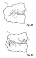
FIG. 3 is a side elevation view of an elongated pressure vessel incorporating an exemplary shape memory alloy trigger for a pressure relief valve of the present disclosure. -
FIG. 4A is a schematic view of a portion of an end section of the pressure vessel ofFIG. 3 , with the pressure relief valve in a closed position. -
FIG. 4B is a schematic view of a portion of an end section of the pressure vessel ofFIG. 3 , with the pressure relief valve in a first open position. -
FIG. 4C is a schematic view of a portion of an end section of the pressure vessel ofFIG. 3 , with the pressure relief valve in a second open position. -
FIG. 5 is a side elevation view of an elongated pressure vessel incorporating an exemplary shape memory alloy trigger connected to a pressure relief valve at each end of the vessel. - While the above-identified figures set forth one or more embodiments of the disclosed subject matter, other embodiments are also contemplated, as noted in the disclosure. In all cases, this disclosure presents the disclosed subject matter by way of representation and not limitation. It should be understood that numerous other modifications and embodiments can be devised by those skilled in the art which fall within the scope of the invention as defined by the claims.
- The figures may not be drawn to scale. In particular, some features may be enlarged relative to other features for clarity. Moreover, where terms such as above, below, over, under, top, bottom, side, right, left, vertical, horizontal, etc., are used, it is to be understood that they are used only for ease of understanding the description. It is contemplated that structures may be oriented otherwise.
- This disclosure provides a sensor and valve assembly for controlled depressurization of a pressure vessel, such as a composite cylindrical gas storage vessel, in particular when the vessel is exposed to a fire. The present disclosure provides a temperature activated sensor and
valve assembly 21 for releasing gas from within the vessel, rather than relieving excess gas using a valve based upon pressure. As illustrated inFIG. 3 , a piece oftubing 22 is mounted on the outside of the pressure vessel 10' to run along the length of vessel 10'. In an exemplary embodiment,tubing 22 is made of stainless steel and has an outside diameter of 6,35 mm (0.25 inch). In an exemplary embodiment,tubing 22 has perforations 40 (shown inFIG. 4C ) to allow freer heat flow intotubing 22. Pressure relief or release valve (PRV) 24 is mounted on boss 16' nearfirst end 26 of tubing 22 (seeFIG. 4A ). - An elongated shape memory alloy (SMA) element, such as
wire 28, is 'set' by straining (stretching of wire 28) approximately 10%. This straining is achieved at a temperature below the SMA's austenite start temperature. Thestrained wire 28 is threaded insidetubing 22, which is fixed relative to alever 32 ofPRV 24. Afirst end 30 of thewire 28 is attached to lever 32 ofPRV 24. Asecond end 34 ofwire 28 is fixed relative totubing 22, such as by being attached to asecond end 36 of tubing 22 (such as by a mechanical fastener or by swaging thesecond end 36 of thetubing 22 over thesecond end 34 of wire 28). In an exemplary embodiment,second end 34 ofwire 28 is positionally fixed relative to pressure vessel 10'. - In an exemplary embodiment,
PRV 24 is a conventional quarter-turn valve.FIG. 4A showsPRV 24 in a closed position, whereinlever 32 is in a vertical position. With such a conventional quarter-turn valve, rotatinglever 32 about ninety degrees (to the positions shown inFIGS. 4B or 4C ) opens the valve, thereby allowing gas to escape from boss 16'. - In an exemplary embodiment, heating of
wire 28 to or beyond its austenite transformation temperature causes thewire 28 to shrink by 6-8 %. Thus for each foot of wire transformed, the strain recovered bywire 28 causes it to shorten by 18,29 mm to 24,38 mm (0.72 to 0.96 inch). As it shortens,first end 30 pulls with a force of approximately 54.43 kg (120 pounds) (for a wire diameter of 1.52 mm (0.06 inch)) and thereby turnslever 32 to openPRV 24. In an exemplary embodiment, the disclosed trigger is designed so that exposure of a requisite portion of the vessel 10' to or in excess of the transformation temperature ofwire 28 causes a shortening ofwire 28 that is adequate to pulllever 32 to the open position illustrated inFIG. 4B . In an exemplary embodiment,PRV 24 is designed to trigger with atotal wire 28 shrinkage of 25.4 mm (1 inch) Whileend 30 ofwire 28 is attached to an end oflever 32 in the illustrated embodiments,wire 28 can be attached to lever 32 at another location, as appropriate for a particular application, taking into account the displacement and pulling force required to openPRV 24. - The heat for triggering sensor and
valve assembly 21 can be present anywhere along the length of theSMA wire 28. In an exemplary embodiment,SMA wire 28 is run in a substantially straight line parallel to the vessel surface along substantially the entire length of vessel 10', thereby protecting the pressure vessel 10' over its entire length. In other embodiments,tubing 22 andwire 28 are run to additional locations where a fire or elevated temperature might be detected. If any portion of thewire 28 is heated past an established temperature, the wire will shrink by a certain degree. If enough of thewire 28 shrinks, movement of theend 30 ofwire 28 pulls onlever 32 to openPRV 24. WithPRV 24 thus opened, pressurized gas from within the vessel 10' can escape through theopen PRV 24 in a controlled manner. - Accordingly,
SMA wire 28 acts as a temperature sensor along the entire length of the vessel 10' and can thus react to localized fires to allow release of gas from vessel 10'. The disclosed trigger arrangement can be used to protect a vessel of any length, even very long pressure vessels. More than onetubing 22 andwire 28 can be used on asingle valve 24. Thetubing 22 andwire 28 are not limited to straight runs, but can be bent, so long as thewire 28 is moveable within thetubing 22. For example,SMA wire 28 laid in a spiral configuration from one end of the tank to the other offers protection on all sides of the tank as well as protection for the length of the tank. Thetubing 22 protects thesensor wire 28 from environmental conditions that might adversely affect its performance. This arrangement results in a relativelyinexpensive sensor assembly 21. The disclosedsensor assembly 21 minimizes false triggering, since thePRV 24 will only be buggered when thewire 28 is exposed to a temperature that exceeds the austenite transformation temperature. The transformation temperature is determined by the wire alloy composition. In one exemplary embodiment, the alloy is 54.79 weight percent Nickel and 45.21 weight percent Titanium and has a transformation temperature of 100°C (212°F). The amount of force can be controlled by selecting the cross-section area (e.g., diameter) of the shape memory element orwire 28. An exemplary wire having a diameter of about 1,52 mm (0.06 inch) produces approximately 54,43 kg (120 pounds) of pull once the ambient temperature exceeds the transformation temperature of the particular alloy. More force is accomplished with a wire having a larger cross-sectional area. The force developed is essentially independent of length and temperature; thus, higher temperatures or more heat input will not significantly increase or decrease the force developed due to transformation. Oncesensor assembly 21 is put in place, it is essentially maintenance free for the life of the pressure vessel 10'. Theshape memory wire 28 is essentially under no stress until transformation occurs. - The pressure release device is also set to be triggered if the
wire 28 is severed. In an exemplary embodiment,lever 32 is biased (such as by spring 38) in the direction shown inFIG. 4C , which is offset from the "off" position ofFIG. 4A by a rotational angle of about 90 degrees (in the direction opposite the offset between the "off" and "on" positions shown inFIGS. 4A and4B , respectively). Thus, ifwire 28 is severed and no longer exerts a pulling force onlever 32,lever 32 automatically springs into the position illustrated inFIG. 4C , thereby openingPRV 24. - In another exemplary embodiment, illustrated in
FIG. 5 ,second end 34 iswire 28 is attached to the lever of a second PRV. This would allow two PRV's to activate, venting the vessel 10' from both ends 14'. In yet another embodiment, the disclosed tubing and SMA valve andsensor assembly 21 can be used to actuate any device (not just a PRV) such as, for example, a fire suppression system. - Although the subject of this disclosure has been described with reference to several embodiments, workers skilled in the art will recognize that changes may be made in form and detail without departing from the scope of the invention as defined by the claims. In addition, any feature disclosed with respect to one embodiment may be incorporated in another embodiment, and vice-versa.
Claims (13)
- An apparatus comprising:a valve comprising a lever (32) in a first position, the valve being closed at the first position;an elongated shape memory alloy element (28) having a first end (30) connected to the lever (32), wherein the shape memory alloy element (28) has been strained to have a first length, wherein exposure of at least a portion of the shape memory alloy element (28) to a temperature at or exceeding its austenite transformation temperature causes the shape memory alloy element (28) to shorten to a second length, the second length being less than the first length, thereby causing the first end (30) of the shape memory alloy element (28) to pull the lever (32) to a second position, the valve being open at the second position, wherein the first position of the lever (32) and the second position of the lever (32) are different; characterized in that the apparatus further comprisesa biasing element (38) that biases the lever (32) to a third position upon severance of the elongated shape memory alloy element (28) such that the elongated shape memory alloy element (28) does not exert a pulling force on the lever (32), wherein the third position of the lever (32) is offset from the first position in a rotation direction opposite that of the offset between the first position of the lever (32) and the second position of the lever (32), and the valve being open at the third position of the lever (32).
- The apparatus of claim 1 wherein the valve is a pressure release valve.
- The apparatus of claim 1 wherein the valve is a quarter-turn valve.
- The apparatus of claim 1 further comprising a tube (22) within which at least a portion of the shape memory alloy element (28) is disposed.
- The apparatus of claim 4 wherein the tube (22) comprises a plurality of perforations (40).
- The apparatus of claim 1 wherein the shape memory alloy element (28) has a second end (34) that is positionally fixed.
- The apparatus of claim 1 wherein the shape memory alloy element (28) has a second end (34) that is connected to a second lever of a second valve.
- The apparatus of claim 1 wherein the first position of the lever (28) and the second position of the lever (28) are offset by a rotational angle of about 90 degrees.
- The apparatus of claim 1 wherein the third position is offset from the first position by a rotational angle of about 90 degrees in a rotation direction opposite that of the offset between the first position of the lever (28) and the second position of the lever (28).
- The apparatus of claim 1 wherein the biasing element (38) is a spring.
- A pressure vessel (10') comprising the apparatus of claim 1.
- The pressure vessel (10') of claim 11 comprising a boss connected to the valve.
- The pressure vessel (10') of claim 12 having the elongated shape memory alloy element (28) positioned along a length of the pressure vessel (10').
Applications Claiming Priority (2)
| Application Number | Priority Date | Filing Date | Title |
|---|---|---|---|
| US15690009P | 2009-03-03 | 2009-03-03 | |
| PCT/US2010/026009 WO2010101976A1 (en) | 2009-03-03 | 2010-03-03 | Shape memory alloy trigger for pressure relief valve |
Publications (2)
| Publication Number | Publication Date |
|---|---|
| EP2404090A1 EP2404090A1 (en) | 2012-01-11 |
| EP2404090B1 true EP2404090B1 (en) | 2015-07-15 |
Family
ID=42174642
Family Applications (1)
| Application Number | Title | Priority Date | Filing Date |
|---|---|---|---|
| EP10707757.0A Active EP2404090B1 (en) | 2009-03-03 | 2010-03-03 | Shape memory alloy trigger for pressure relief valve |
Country Status (11)
| Country | Link |
|---|---|
| US (1) | US8820069B2 (en) |
| EP (1) | EP2404090B1 (en) |
| JP (1) | JP5738776B2 (en) |
| KR (1) | KR101501048B1 (en) |
| CN (1) | CN102341630B (en) |
| AU (1) | AU2010221443B2 (en) |
| BR (1) | BRPI1007868B1 (en) |
| CA (1) | CA2753386C (en) |
| ES (1) | ES2547280T3 (en) |
| RU (1) | RU2500943C2 (en) |
| WO (1) | WO2010101976A1 (en) |
Families Citing this family (25)
| Publication number | Priority date | Publication date | Assignee | Title |
|---|---|---|---|---|
| US8720722B2 (en) * | 2005-12-15 | 2014-05-13 | Cornerstone Research Group, Inc. | Venting mechanism for containers |
| US10226991B2 (en) * | 2009-10-28 | 2019-03-12 | GM Global Technology Operations LLC | Air curtain using smart materials |
| DE102011001140A1 (en) * | 2011-03-08 | 2012-09-13 | Thyssenkrupp Steel Europe Ag | Flat steel product, method for producing a flat steel product and method for producing a component |
| US10407760B2 (en) * | 2011-09-30 | 2019-09-10 | Nippon Steel Corporation | Hot-dip galvanized steel sheet and manufacturing method thereof |
| DE112013006786T5 (en) | 2013-03-06 | 2015-12-03 | Kongsberg Automotive Ab | Fluid flow path adjustment device with a shape memory alloy element |
| US9097358B2 (en) * | 2013-05-01 | 2015-08-04 | Emcara Gas Development Inc. | Valve with temperature activated trigger having novel material configuration |
| DE112013007682T5 (en) | 2013-12-13 | 2016-09-22 | Kongsberg Automotive Ab | SMA valve for controlling the supply of air to an air cell in a vehicle seat |
| CN105829164B (en) | 2013-12-13 | 2019-01-18 | 康斯博格汽车股份公司 | For controlling the SMA valve to the Pressurized air supply of air element in vehicle seat |
| CN105813887B (en) | 2013-12-13 | 2017-11-10 | 康斯博格汽车股份公司 | For controlling the SMA valves to the Pressurized air supply of air element in seat |
| DE102014000616A1 (en) | 2014-01-18 | 2015-07-23 | Daimler Ag | Thermally triggered safety valve |
| DE112014006722T5 (en) | 2014-06-04 | 2017-03-02 | Kongsberg Automotive Ab | SMA valve for controlling the supply of compressed air to an air cell in a vehicle seat |
| CN104197188B (en) * | 2014-08-25 | 2017-02-01 | 上海宇航系统工程研究所 | Gas jetting device driven by shape memory alloy wires |
| GB2531265A (en) * | 2014-10-13 | 2016-04-20 | Graviner Ltd Kidde | A frangible plug for use in a valve mechanism |
| US9416878B1 (en) | 2015-02-16 | 2016-08-16 | Kongsberg Automotive, Inc. | Valve including a shape memory alloy member |
| NO20150851A1 (en) * | 2015-07-01 | 2016-09-12 | Techinvent As | An apparatus for controlling a fluid flow |
| CN108730604A (en) * | 2017-04-14 | 2018-11-02 | 国家电力投资集团公司 | Passive valve system |
| CN107327692A (en) * | 2017-07-17 | 2017-11-07 | 凯迈(洛阳)气源有限公司 | A kind of aircraft gas cylinder |
| EP3672823B1 (en) | 2017-09-14 | 2023-07-19 | Agility Fuel Systems LLC | Systems for monitoring volatile fuel system components |
| US10942533B2 (en) | 2018-02-14 | 2021-03-09 | Hexagon Technology As | System for multiple pressure relief device activation |
| EP3903017B1 (en) * | 2019-03-12 | 2023-03-22 | Nikola Corporation | Pressurized vessel heat shield and thermal pressure relief system |
| KR102187342B1 (en) | 2019-09-03 | 2020-12-04 | (주)삼익브리즈 | Relief valve for preventing frost |
| EP4031799A4 (en) | 2019-11-25 | 2023-10-25 | Agility Fuel Systems LLC | Improved pressure relief device |
| CN113124247B (en) * | 2021-04-30 | 2022-05-20 | 中国工程物理研究院机械制造工艺研究所 | Pipeline sealing structure capable of realizing high-temperature air leakage safety protection, pipeline sealing and high-temperature air leakage method |
| CN113431915B (en) * | 2021-07-02 | 2023-01-24 | 威海观复燃气安全科技有限公司 | Liquefied petroleum gas self-closing valve |
| CN114877111B (en) * | 2022-07-12 | 2022-12-09 | 山东拙诚智能科技有限公司 | Gas safety control device |
Family Cites Families (49)
| Publication number | Priority date | Publication date | Assignee | Title |
|---|---|---|---|---|
| FR1115990A (en) * | 1953-11-16 | 1956-05-02 | Gen Motors Corp | Advanced refrigerator |
| US3489309A (en) | 1966-12-13 | 1970-01-13 | Foster Wheeler Corp | Pressure vessels |
| US3613732A (en) | 1969-07-17 | 1971-10-19 | Robertshaw Controls Co | Temperature-responsive valve operators |
| US3914991A (en) | 1973-07-24 | 1975-10-28 | Nasa | Strain gage mounting assembly |
| DE2728651C2 (en) | 1977-06-24 | 1981-09-17 | Siempelkamp Gießerei GmbH & Co, 4150 Krefeld | Method for monitoring a cylindrical nuclear reactor pressure vessel and devices for carrying out such a method |
| US4284235A (en) * | 1979-12-19 | 1981-08-18 | Werner Diermayer | Vent control arrangement for combustion apparatus |
| JPS5874666U (en) * | 1981-11-13 | 1983-05-20 | 東北金属工業株式会社 | temperature sensitive valve |
| JPS58132273A (en) * | 1982-02-02 | 1983-08-06 | 日本電信電話株式会社 | Flexible dispersion type el matrix display element |
| JPS58132273U (en) * | 1982-03-03 | 1983-09-06 | 奥原 克美 | Gas leak prevention device |
| US4570851A (en) | 1984-05-07 | 1986-02-18 | Cirillo John R | Temperature regulating, pressure relief flow valves employing shaped memory alloys |
| JPS61121341A (en) | 1984-11-16 | 1986-06-09 | Mitsubishi Electric Corp | Manufacture of glass passivation type semiconductor device |
| JPS61121341U (en) * | 1985-01-16 | 1986-07-31 | ||
| US4840346A (en) * | 1985-04-11 | 1989-06-20 | Memory Metals, Inc. | Apparatus for sealing a well blowout |
| US4884780A (en) * | 1985-04-26 | 1989-12-05 | Nissan Motor Company, Limited | Valve actuating arrangement |
| JPS61183417U (en) * | 1985-05-07 | 1986-11-15 | ||
| JPS62129487A (en) * | 1985-11-30 | 1987-06-11 | 大同特殊鋼株式会社 | Opening and closing drive apparatus of opening and closing panel |
| US4699314A (en) * | 1986-12-17 | 1987-10-13 | Carrier Corporation | Actuator for a heating/cooling diffuser |
| JPS63162265A (en) * | 1986-12-26 | 1988-07-05 | Canon Inc | Printer |
| JPS63162265U (en) * | 1987-04-08 | 1988-10-24 | ||
| US4965545A (en) * | 1989-08-09 | 1990-10-23 | Tini Alloy Company | Shape memory alloy rotary actuator |
| US4973024A (en) * | 1989-09-26 | 1990-11-27 | Toki Corporation Kabushiki Kaisha | Valve driven by shape memory alloy |
| US5277028A (en) | 1990-03-26 | 1994-01-11 | Mercedes-Benz Ag | Hydraulic flow control with temperature sensitive spring biased bypass valve |
| US5211371A (en) * | 1991-07-22 | 1993-05-18 | Advanced Control Technologies, Inc. | Linearly actuated valve |
| US5165450A (en) * | 1991-12-23 | 1992-11-24 | Texaco Inc. | Means for separating a fluid stream into two separate streams |
| GB2272276B (en) * | 1992-11-06 | 1995-03-29 | Kim San Toh | Improvements in LPG cylinders |
| US5476189A (en) | 1993-12-03 | 1995-12-19 | Duvall; Paul F. | Pressure vessel with damage mitigating system |
| US5522428A (en) | 1994-08-29 | 1996-06-04 | Duvall; Paul F. | Natural gas vehicle tank life sensor and control |
| US5518140A (en) | 1994-11-07 | 1996-05-21 | Cryenco, Inc. | Liquified gas storage tank overfill protection system and method |
| US5462226A (en) * | 1994-11-07 | 1995-10-31 | Itt Corporation | Temperature-responsive, locking mechanism for, and in combination with, a fluid valve |
| US5586722A (en) | 1995-05-05 | 1996-12-24 | Murray; Jerome L. | Temperature and flow control valve |
| US5662139A (en) * | 1995-09-08 | 1997-09-02 | Lish; Dennis N. | Pressure relief valve with lockout position |
| US5788212A (en) | 1996-07-26 | 1998-08-04 | Gas Research Institute | Pressure relief device with shaped memory alloy thermally activated trigger |
| US5865418A (en) * | 1996-11-08 | 1999-02-02 | Matsushita Electric Works, Ltd. | Flow control valve |
| US6269830B1 (en) | 1998-09-28 | 2001-08-07 | Gas Research Institute | Extended area thermal activation device |
| JP3065038U (en) * | 1999-04-22 | 2000-01-28 | 國弘 主税 | Automatic opening device for fire extinguisher cylinders using the contraction force of shape memory alloy |
| FR2796701B1 (en) * | 1999-07-22 | 2001-09-07 | Giat Ind Sa | SAFETY VALVE FOR A SEALED ENCLOSURE CONTAINING A PRESSURE FLUID SUCH AS AN LPG TANK |
| RU2188683C1 (en) * | 2000-12-28 | 2002-09-10 | Сильянов Виталий Анатольевич | Fire extinguisher |
| WO2002057627A1 (en) * | 2001-01-17 | 2002-07-25 | M 2 Medical A/S | Shape memory alloy actuator |
| ATE301261T1 (en) | 2001-05-08 | 2005-08-15 | Alberto Arena | PROPORTIONAL VALVE WITH A SHAPE MEMORY ALLOY ACTUATOR |
| ITTO20010618A1 (en) * | 2001-06-27 | 2002-12-27 | Fiat Ricerche | FLEXIBLE CABLE ACTUATOR DEVICE INCORPORATING A SHAPE MEMORY ELEMENT. |
| CN1685150A (en) * | 2002-07-24 | 2005-10-19 | M2医药有限公司 | Shape memory alloy actuator |
| US6955187B1 (en) * | 2003-07-16 | 2005-10-18 | Tini Alloy Company | Zinc-air battery control valve |
| ITTO20030553A1 (en) * | 2003-07-17 | 2005-01-18 | Fiat Ricerche | FLUIDO FLOW CONTROL DEVICE |
| WO2005026592A2 (en) * | 2003-09-05 | 2005-03-24 | Alfmeier Präzision AG Baugruppen und Systemlösungen | A system, method and apparatus for reducing frictional forces and for compensating shape memory alloy-actuated valves and valve systems at high temperatures |
| US20080148853A1 (en) | 2003-09-22 | 2008-06-26 | Hyeung-Yun Kim | Gas tank having usage monitoring system |
| DE102004062241A1 (en) * | 2004-12-23 | 2006-07-13 | BSH Bosch und Siemens Hausgeräte GmbH | Actuator for valves |
| KR100966945B1 (en) * | 2005-07-26 | 2010-06-30 | 파나소닉 전공 주식회사 | Compact valve |
| US20080319688A1 (en) | 2007-02-26 | 2008-12-25 | Hyeung-Yun Kim | Usage monitoring system of gas tank |
| US8499779B2 (en) * | 2008-01-16 | 2013-08-06 | The United States Of America As Represented By The Administrator Of The National Aeronautics Space Administration | Systems, methods and apparatus of a nitinol valve |
-
2010
- 2010-03-03 RU RU2011139966/06A patent/RU2500943C2/en active
- 2010-03-03 KR KR1020117022777A patent/KR101501048B1/en active IP Right Grant
- 2010-03-03 JP JP2011553064A patent/JP5738776B2/en active Active
- 2010-03-03 CN CN2010800102698A patent/CN102341630B/en not_active Expired - Fee Related
- 2010-03-03 AU AU2010221443A patent/AU2010221443B2/en not_active Ceased
- 2010-03-03 EP EP10707757.0A patent/EP2404090B1/en active Active
- 2010-03-03 WO PCT/US2010/026009 patent/WO2010101976A1/en active Application Filing
- 2010-03-03 ES ES10707757.0T patent/ES2547280T3/en active Active
- 2010-03-03 BR BRPI1007868-1A patent/BRPI1007868B1/en not_active IP Right Cessation
- 2010-03-03 US US13/254,346 patent/US8820069B2/en active Active
- 2010-03-03 CA CA2753386A patent/CA2753386C/en active Active
Also Published As
| Publication number | Publication date |
|---|---|
| BRPI1007868A2 (en) | 2018-02-14 |
| EP2404090A1 (en) | 2012-01-11 |
| US8820069B2 (en) | 2014-09-02 |
| RU2500943C2 (en) | 2013-12-10 |
| AU2010221443B2 (en) | 2014-11-27 |
| CA2753386A1 (en) | 2010-09-10 |
| ES2547280T3 (en) | 2015-10-02 |
| BRPI1007868B1 (en) | 2020-09-15 |
| JP5738776B2 (en) | 2015-06-24 |
| WO2010101976A1 (en) | 2010-09-10 |
| RU2011139966A (en) | 2013-04-10 |
| KR20110128321A (en) | 2011-11-29 |
| CN102341630A (en) | 2012-02-01 |
| CA2753386C (en) | 2015-08-11 |
| JP2012519816A (en) | 2012-08-30 |
| CN102341630B (en) | 2013-09-18 |
| KR101501048B1 (en) | 2015-03-10 |
| US20120011843A1 (en) | 2012-01-19 |
| AU2010221443A1 (en) | 2011-09-08 |
Similar Documents
| Publication | Publication Date | Title |
|---|---|---|
| EP2404090B1 (en) | Shape memory alloy trigger for pressure relief valve | |
| US10168002B2 (en) | Breather layer for exhausting permeate from pressure vessels | |
| EP0656506B1 (en) | Pressure vessel with damage mitigating system | |
| CN108930790B (en) | High pressure vessel | |
| US5615702A (en) | Tank for storing pressurized hydrocarbons | |
| AU2007246823B2 (en) | Improvements relating to hose | |
| AU633945B2 (en) | Protective device for gas pressure vessels | |
| EP3380779B1 (en) | Composite vessel fire protection system | |
| US11098851B2 (en) | High-pressure tank and attachment structure thereof | |
| US20200109791A1 (en) | Pressure-Relief Device With a Variable Mass Flow Rate | |
| JPS61500371A (en) | flexible tubular conduit | |
| US20230046665A1 (en) | End fitting for a pressurized fluid reservoir | |
| JP2023174124A (en) | fluid tank |
Legal Events
| Date | Code | Title | Description |
|---|---|---|---|
| PUAI | Public reference made under article 153(3) epc to a published international application that has entered the european phase |
Free format text: ORIGINAL CODE: 0009012 |
|
| 17P | Request for examination filed |
Effective date: 20110922 |
|
| AK | Designated contracting states |
Kind code of ref document: A1 Designated state(s): AT BE BG CH CY CZ DE DK EE ES FI FR GB GR HR HU IE IS IT LI LT LU LV MC MK MT NL NO PL PT RO SE SI SK SM TR |
|
| DAX | Request for extension of the european patent (deleted) | ||
| 17Q | First examination report despatched |
Effective date: 20130301 |
|
| GRAP | Despatch of communication of intention to grant a patent |
Free format text: ORIGINAL CODE: EPIDOSNIGR1 |
|
| INTG | Intention to grant announced |
Effective date: 20150217 |
|
| GRAS | Grant fee paid |
Free format text: ORIGINAL CODE: EPIDOSNIGR3 |
|
| GRAA | (expected) grant |
Free format text: ORIGINAL CODE: 0009210 |
|
| AK | Designated contracting states |
Kind code of ref document: B1 Designated state(s): AT BE BG CH CY CZ DE DK EE ES FI FR GB GR HR HU IE IS IT LI LT LU LV MC MK MT NL NO PL PT RO SE SI SK SM TR |
|
| REG | Reference to a national code |
Ref country code: CH Ref legal event code: EP Ref country code: GB Ref legal event code: FG4D |
|
| REG | Reference to a national code |
Ref country code: IE Ref legal event code: FG4D |
|
| REG | Reference to a national code |
Ref country code: AT Ref legal event code: REF Ref document number: 736972 Country of ref document: AT Kind code of ref document: T Effective date: 20150815 |
|
| REG | Reference to a national code |
Ref country code: DE Ref legal event code: R096 Ref document number: 602010025890 Country of ref document: DE |
|
| REG | Reference to a national code |
Ref country code: ES Ref legal event code: FG2A Ref document number: 2547280 Country of ref document: ES Kind code of ref document: T3 Effective date: 20151002 |
|
| REG | Reference to a national code |
Ref country code: CH Ref legal event code: NV Representative=s name: ICB INGENIEURS CONSEILS EN BREVETS SA, CH |
|
| REG | Reference to a national code |
Ref country code: SE Ref legal event code: TRGR |
|
| REG | Reference to a national code |
Ref country code: NO Ref legal event code: T2 Effective date: 20150715 |
|
| REG | Reference to a national code |
Ref country code: NL Ref legal event code: MP Effective date: 20150715 |
|
| REG | Reference to a national code |
Ref country code: LT Ref legal event code: MG4D |
|
| PG25 | Lapsed in a contracting state [announced via postgrant information from national office to epo] |
Ref country code: LT Free format text: LAPSE BECAUSE OF FAILURE TO SUBMIT A TRANSLATION OF THE DESCRIPTION OR TO PAY THE FEE WITHIN THE PRESCRIBED TIME-LIMIT Effective date: 20150715 Ref country code: LV Free format text: LAPSE BECAUSE OF FAILURE TO SUBMIT A TRANSLATION OF THE DESCRIPTION OR TO PAY THE FEE WITHIN THE PRESCRIBED TIME-LIMIT Effective date: 20150715 Ref country code: FI Free format text: LAPSE BECAUSE OF FAILURE TO SUBMIT A TRANSLATION OF THE DESCRIPTION OR TO PAY THE FEE WITHIN THE PRESCRIBED TIME-LIMIT Effective date: 20150715 Ref country code: GR Free format text: LAPSE BECAUSE OF FAILURE TO SUBMIT A TRANSLATION OF THE DESCRIPTION OR TO PAY THE FEE WITHIN THE PRESCRIBED TIME-LIMIT Effective date: 20151016 |
|
| PG25 | Lapsed in a contracting state [announced via postgrant information from national office to epo] |
Ref country code: PT Free format text: LAPSE BECAUSE OF FAILURE TO SUBMIT A TRANSLATION OF THE DESCRIPTION OR TO PAY THE FEE WITHIN THE PRESCRIBED TIME-LIMIT Effective date: 20151116 Ref country code: HR Free format text: LAPSE BECAUSE OF FAILURE TO SUBMIT A TRANSLATION OF THE DESCRIPTION OR TO PAY THE FEE WITHIN THE PRESCRIBED TIME-LIMIT Effective date: 20150715 Ref country code: PL Free format text: LAPSE BECAUSE OF FAILURE TO SUBMIT A TRANSLATION OF THE DESCRIPTION OR TO PAY THE FEE WITHIN THE PRESCRIBED TIME-LIMIT Effective date: 20150715 |
|
| REG | Reference to a national code |
Ref country code: FR Ref legal event code: PLFP Year of fee payment: 7 |
|
| REG | Reference to a national code |
Ref country code: DE Ref legal event code: R097 Ref document number: 602010025890 Country of ref document: DE |
|
| PG25 | Lapsed in a contracting state [announced via postgrant information from national office to epo] |
Ref country code: SK Free format text: LAPSE BECAUSE OF FAILURE TO SUBMIT A TRANSLATION OF THE DESCRIPTION OR TO PAY THE FEE WITHIN THE PRESCRIBED TIME-LIMIT Effective date: 20150715 Ref country code: DK Free format text: LAPSE BECAUSE OF FAILURE TO SUBMIT A TRANSLATION OF THE DESCRIPTION OR TO PAY THE FEE WITHIN THE PRESCRIBED TIME-LIMIT Effective date: 20150715 Ref country code: EE Free format text: LAPSE BECAUSE OF FAILURE TO SUBMIT A TRANSLATION OF THE DESCRIPTION OR TO PAY THE FEE WITHIN THE PRESCRIBED TIME-LIMIT Effective date: 20150715 Ref country code: CZ Free format text: LAPSE BECAUSE OF FAILURE TO SUBMIT A TRANSLATION OF THE DESCRIPTION OR TO PAY THE FEE WITHIN THE PRESCRIBED TIME-LIMIT Effective date: 20150715 |
|
| PLBE | No opposition filed within time limit |
Free format text: ORIGINAL CODE: 0009261 |
|
| STAA | Information on the status of an ep patent application or granted ep patent |
Free format text: STATUS: NO OPPOSITION FILED WITHIN TIME LIMIT |
|
| PG25 | Lapsed in a contracting state [announced via postgrant information from national office to epo] |
Ref country code: RO Free format text: LAPSE BECAUSE OF FAILURE TO SUBMIT A TRANSLATION OF THE DESCRIPTION OR TO PAY THE FEE WITHIN THE PRESCRIBED TIME-LIMIT Effective date: 20150715 |
|
| 26N | No opposition filed |
Effective date: 20160418 |
|
| PG25 | Lapsed in a contracting state [announced via postgrant information from national office to epo] |
Ref country code: IS Free format text: LAPSE BECAUSE OF FAILURE TO SUBMIT A TRANSLATION OF THE DESCRIPTION OR TO PAY THE FEE WITHIN THE PRESCRIBED TIME-LIMIT Effective date: 20150715 |
|
| PG25 | Lapsed in a contracting state [announced via postgrant information from national office to epo] |
Ref country code: BE Free format text: LAPSE BECAUSE OF NON-PAYMENT OF DUE FEES Effective date: 20160331 Ref country code: SI Free format text: LAPSE BECAUSE OF FAILURE TO SUBMIT A TRANSLATION OF THE DESCRIPTION OR TO PAY THE FEE WITHIN THE PRESCRIBED TIME-LIMIT Effective date: 20150715 |
|
| PG25 | Lapsed in a contracting state [announced via postgrant information from national office to epo] |
Ref country code: LU Free format text: LAPSE BECAUSE OF FAILURE TO SUBMIT A TRANSLATION OF THE DESCRIPTION OR TO PAY THE FEE WITHIN THE PRESCRIBED TIME-LIMIT Effective date: 20160303 Ref country code: MC Free format text: LAPSE BECAUSE OF FAILURE TO SUBMIT A TRANSLATION OF THE DESCRIPTION OR TO PAY THE FEE WITHIN THE PRESCRIBED TIME-LIMIT Effective date: 20150715 |
|
| REG | Reference to a national code |
Ref country code: IE Ref legal event code: MM4A |
|
| PG25 | Lapsed in a contracting state [announced via postgrant information from national office to epo] |
Ref country code: BE Free format text: LAPSE BECAUSE OF FAILURE TO SUBMIT A TRANSLATION OF THE DESCRIPTION OR TO PAY THE FEE WITHIN THE PRESCRIBED TIME-LIMIT Effective date: 20150715 |
|
| PG25 | Lapsed in a contracting state [announced via postgrant information from national office to epo] |
Ref country code: IE Free format text: LAPSE BECAUSE OF NON-PAYMENT OF DUE FEES Effective date: 20160303 |
|
| REG | Reference to a national code |
Ref country code: FR Ref legal event code: PLFP Year of fee payment: 8 |
|
| PG25 | Lapsed in a contracting state [announced via postgrant information from national office to epo] |
Ref country code: NL Free format text: LAPSE BECAUSE OF FAILURE TO SUBMIT A TRANSLATION OF THE DESCRIPTION OR TO PAY THE FEE WITHIN THE PRESCRIBED TIME-LIMIT Effective date: 20150715 |
|
| REG | Reference to a national code |
Ref country code: AT Ref legal event code: UEP Ref document number: 736972 Country of ref document: AT Kind code of ref document: T Effective date: 20150715 |
|
| PG25 | Lapsed in a contracting state [announced via postgrant information from national office to epo] |
Ref country code: MT Free format text: LAPSE BECAUSE OF FAILURE TO SUBMIT A TRANSLATION OF THE DESCRIPTION OR TO PAY THE FEE WITHIN THE PRESCRIBED TIME-LIMIT Effective date: 20150715 |
|
| REG | Reference to a national code |
Ref country code: FR Ref legal event code: PLFP Year of fee payment: 9 |
|
| PG25 | Lapsed in a contracting state [announced via postgrant information from national office to epo] |
Ref country code: HU Free format text: LAPSE BECAUSE OF FAILURE TO SUBMIT A TRANSLATION OF THE DESCRIPTION OR TO PAY THE FEE WITHIN THE PRESCRIBED TIME-LIMIT; INVALID AB INITIO Effective date: 20100303 Ref country code: CY Free format text: LAPSE BECAUSE OF FAILURE TO SUBMIT A TRANSLATION OF THE DESCRIPTION OR TO PAY THE FEE WITHIN THE PRESCRIBED TIME-LIMIT Effective date: 20150715 Ref country code: SM Free format text: LAPSE BECAUSE OF FAILURE TO SUBMIT A TRANSLATION OF THE DESCRIPTION OR TO PAY THE FEE WITHIN THE PRESCRIBED TIME-LIMIT Effective date: 20150715 |
|
| PG25 | Lapsed in a contracting state [announced via postgrant information from national office to epo] |
Ref country code: MT Free format text: LAPSE BECAUSE OF FAILURE TO SUBMIT A TRANSLATION OF THE DESCRIPTION OR TO PAY THE FEE WITHIN THE PRESCRIBED TIME-LIMIT Effective date: 20160331 Ref country code: MK Free format text: LAPSE BECAUSE OF FAILURE TO SUBMIT A TRANSLATION OF THE DESCRIPTION OR TO PAY THE FEE WITHIN THE PRESCRIBED TIME-LIMIT Effective date: 20150715 |
|
| PG25 | Lapsed in a contracting state [announced via postgrant information from national office to epo] |
Ref country code: BG Free format text: LAPSE BECAUSE OF FAILURE TO SUBMIT A TRANSLATION OF THE DESCRIPTION OR TO PAY THE FEE WITHIN THE PRESCRIBED TIME-LIMIT Effective date: 20150715 |
|
| PGFP | Annual fee paid to national office [announced via postgrant information from national office to epo] |
Ref country code: AT Payment date: 20200219 Year of fee payment: 11 Ref country code: SE Payment date: 20200327 Year of fee payment: 11 |
|
| PGFP | Annual fee paid to national office [announced via postgrant information from national office to epo] |
Ref country code: CH Payment date: 20200401 Year of fee payment: 11 |
|
| REG | Reference to a national code |
Ref country code: CH Ref legal event code: PL |
|
| REG | Reference to a national code |
Ref country code: AT Ref legal event code: MM01 Ref document number: 736972 Country of ref document: AT Kind code of ref document: T Effective date: 20210303 |
|
| PG25 | Lapsed in a contracting state [announced via postgrant information from national office to epo] |
Ref country code: LI Free format text: LAPSE BECAUSE OF NON-PAYMENT OF DUE FEES Effective date: 20210331 Ref country code: CH Free format text: LAPSE BECAUSE OF NON-PAYMENT OF DUE FEES Effective date: 20210331 Ref country code: AT Free format text: LAPSE BECAUSE OF NON-PAYMENT OF DUE FEES Effective date: 20210303 Ref country code: SE Free format text: LAPSE BECAUSE OF NON-PAYMENT OF DUE FEES Effective date: 20210304 |
|
| PGFP | Annual fee paid to national office [announced via postgrant information from national office to epo] |
Ref country code: TR Payment date: 20220224 Year of fee payment: 13 Ref country code: NO Payment date: 20220329 Year of fee payment: 13 |
|
| PGFP | Annual fee paid to national office [announced via postgrant information from national office to epo] |
Ref country code: ES Payment date: 20220401 Year of fee payment: 13 |
|
| PGFP | Annual fee paid to national office [announced via postgrant information from national office to epo] |
Ref country code: FR Payment date: 20230328 Year of fee payment: 14 |
|
| PGFP | Annual fee paid to national office [announced via postgrant information from national office to epo] |
Ref country code: IT Payment date: 20230321 Year of fee payment: 14 |
|
| P01 | Opt-out of the competence of the unified patent court (upc) registered |
Effective date: 20230518 |
|
| REG | Reference to a national code |
Ref country code: NO Ref legal event code: MMEP |
|
| PG25 | Lapsed in a contracting state [announced via postgrant information from national office to epo] |
Ref country code: NO Free format text: LAPSE BECAUSE OF NON-PAYMENT OF DUE FEES Effective date: 20230331 |
|
| PG25 | Lapsed in a contracting state [announced via postgrant information from national office to epo] |
Ref country code: ES Free format text: LAPSE BECAUSE OF NON-PAYMENT OF DUE FEES Effective date: 20230304 |
|
| REG | Reference to a national code |
Ref country code: ES Ref legal event code: FD2A Effective date: 20240426 |
|
| PG25 | Lapsed in a contracting state [announced via postgrant information from national office to epo] |
Ref country code: ES Free format text: LAPSE BECAUSE OF NON-PAYMENT OF DUE FEES Effective date: 20230304 |
|
| PGFP | Annual fee paid to national office [announced via postgrant information from national office to epo] |
Ref country code: DE Payment date: 20240327 Year of fee payment: 15 Ref country code: GB Payment date: 20240327 Year of fee payment: 15 |