BRPI1007868B1 - APPLIANCE UNDERSTANDING SHAPE MEMORY ALLOY TRIGGER FOR PRESSURE RELIEF VALVE - Google Patents
APPLIANCE UNDERSTANDING SHAPE MEMORY ALLOY TRIGGER FOR PRESSURE RELIEF VALVE Download PDFInfo
- Publication number
- BRPI1007868B1 BRPI1007868B1 BRPI1007868-1A BRPI1007868A BRPI1007868B1 BR PI1007868 B1 BRPI1007868 B1 BR PI1007868B1 BR PI1007868 A BRPI1007868 A BR PI1007868A BR PI1007868 B1 BRPI1007868 B1 BR PI1007868B1
- Authority
- BR
- Brazil
- Prior art keywords
- lever
- valve
- memory alloy
- shape memory
- alloy element
- Prior art date
Links
- 229910001285 shape-memory alloy Inorganic materials 0.000 title claims abstract description 32
- 230000009466 transformation Effects 0.000 claims abstract description 10
- 229910001566 austenite Inorganic materials 0.000 claims abstract description 6
- 238000006073 displacement reaction Methods 0.000 claims description 3
- 238000005192 partition Methods 0.000 claims 1
- 239000007789 gas Substances 0.000 description 11
- 239000002131 composite material Substances 0.000 description 8
- 229910045601 alloy Inorganic materials 0.000 description 3
- 239000000956 alloy Substances 0.000 description 3
- IJGRMHOSHXDMSA-UHFFFAOYSA-N Atomic nitrogen Chemical compound N#N IJGRMHOSHXDMSA-UHFFFAOYSA-N 0.000 description 2
- PXHVJJICTQNCMI-UHFFFAOYSA-N Nickel Chemical compound [Ni] PXHVJJICTQNCMI-UHFFFAOYSA-N 0.000 description 2
- ATUOYWHBWRKTHZ-UHFFFAOYSA-N Propane Chemical compound CCC ATUOYWHBWRKTHZ-UHFFFAOYSA-N 0.000 description 2
- 229910000831 Steel Inorganic materials 0.000 description 2
- 230000004913 activation Effects 0.000 description 2
- 238000010276 construction Methods 0.000 description 2
- 239000012530 fluid Substances 0.000 description 2
- VNWKTOKETHGBQD-UHFFFAOYSA-N methane Chemical compound C VNWKTOKETHGBQD-UHFFFAOYSA-N 0.000 description 2
- 239000010959 steel Substances 0.000 description 2
- 241000701093 Suid alphaherpesvirus 1 Species 0.000 description 1
- RTAQQCXQSZGOHL-UHFFFAOYSA-N Titanium Chemical compound [Ti] RTAQQCXQSZGOHL-UHFFFAOYSA-N 0.000 description 1
- 230000002411 adverse Effects 0.000 description 1
- 229910052782 aluminium Inorganic materials 0.000 description 1
- XAGFODPZIPBFFR-UHFFFAOYSA-N aluminium Chemical compound [Al] XAGFODPZIPBFFR-UHFFFAOYSA-N 0.000 description 1
- QVGXLLKOCUKJST-UHFFFAOYSA-N atomic oxygen Chemical compound [O] QVGXLLKOCUKJST-UHFFFAOYSA-N 0.000 description 1
- 230000004888 barrier function Effects 0.000 description 1
- 230000015572 biosynthetic process Effects 0.000 description 1
- 239000011248 coating agent Substances 0.000 description 1
- 238000000576 coating method Methods 0.000 description 1
- 238000004891 communication Methods 0.000 description 1
- 150000001875 compounds Chemical class 0.000 description 1
- 239000012611 container material Substances 0.000 description 1
- 230000007797 corrosion Effects 0.000 description 1
- 238000005260 corrosion Methods 0.000 description 1
- 230000008878 coupling Effects 0.000 description 1
- 238000010168 coupling process Methods 0.000 description 1
- 238000005859 coupling reaction Methods 0.000 description 1
- 230000007613 environmental effect Effects 0.000 description 1
- 238000004880 explosion Methods 0.000 description 1
- 238000005242 forging Methods 0.000 description 1
- 239000000446 fuel Substances 0.000 description 1
- 239000003365 glass fiber Substances 0.000 description 1
- 238000010438 heat treatment Methods 0.000 description 1
- 239000001257 hydrogen Substances 0.000 description 1
- 229910052739 hydrogen Inorganic materials 0.000 description 1
- 125000004435 hydrogen atom Chemical class [H]* 0.000 description 1
- 238000012423 maintenance Methods 0.000 description 1
- 239000011159 matrix material Substances 0.000 description 1
- 239000000203 mixture Substances 0.000 description 1
- 238000012986 modification Methods 0.000 description 1
- 230000004048 modification Effects 0.000 description 1
- 239000003345 natural gas Substances 0.000 description 1
- 229910052759 nickel Inorganic materials 0.000 description 1
- 229910052757 nitrogen Inorganic materials 0.000 description 1
- 229910052755 nonmetal Inorganic materials 0.000 description 1
- 239000001301 oxygen Substances 0.000 description 1
- 229910052760 oxygen Inorganic materials 0.000 description 1
- 229920000642 polymer Polymers 0.000 description 1
- 239000001294 propane Substances 0.000 description 1
- 230000001105 regulatory effect Effects 0.000 description 1
- 239000012783 reinforcing fiber Substances 0.000 description 1
- 229920005989 resin Polymers 0.000 description 1
- 239000011347 resin Substances 0.000 description 1
- 238000004904 shortening Methods 0.000 description 1
- 239000010935 stainless steel Substances 0.000 description 1
- 229910001220 stainless steel Inorganic materials 0.000 description 1
- 229920005992 thermoplastic resin Polymers 0.000 description 1
- 229920001187 thermosetting polymer Polymers 0.000 description 1
- 239000010936 titanium Substances 0.000 description 1
- 229910052719 titanium Inorganic materials 0.000 description 1
- 238000013022 venting Methods 0.000 description 1
Images

Classifications
-
- F—MECHANICAL ENGINEERING; LIGHTING; HEATING; WEAPONS; BLASTING
- F16—ENGINEERING ELEMENTS AND UNITS; GENERAL MEASURES FOR PRODUCING AND MAINTAINING EFFECTIVE FUNCTIONING OF MACHINES OR INSTALLATIONS; THERMAL INSULATION IN GENERAL
- F16K—VALVES; TAPS; COCKS; ACTUATING-FLOATS; DEVICES FOR VENTING OR AERATING
- F16K17/00—Safety valves; Equalising valves, e.g. pressure relief valves
- F16K17/36—Safety valves; Equalising valves, e.g. pressure relief valves actuated in consequence of extraneous circumstances, e.g. shock, change of position
- F16K17/38—Safety valves; Equalising valves, e.g. pressure relief valves actuated in consequence of extraneous circumstances, e.g. shock, change of position of excessive temperature
- F16K17/386—Safety valves; Equalising valves, e.g. pressure relief valves actuated in consequence of extraneous circumstances, e.g. shock, change of position of excessive temperature the closure members being rotatable or pivoting
-
- F—MECHANICAL ENGINEERING; LIGHTING; HEATING; WEAPONS; BLASTING
- F16—ENGINEERING ELEMENTS AND UNITS; GENERAL MEASURES FOR PRODUCING AND MAINTAINING EFFECTIVE FUNCTIONING OF MACHINES OR INSTALLATIONS; THERMAL INSULATION IN GENERAL
- F16K—VALVES; TAPS; COCKS; ACTUATING-FLOATS; DEVICES FOR VENTING OR AERATING
- F16K31/00—Actuating devices; Operating means; Releasing devices
-
- F—MECHANICAL ENGINEERING; LIGHTING; HEATING; WEAPONS; BLASTING
- F16—ENGINEERING ELEMENTS AND UNITS; GENERAL MEASURES FOR PRODUCING AND MAINTAINING EFFECTIVE FUNCTIONING OF MACHINES OR INSTALLATIONS; THERMAL INSULATION IN GENERAL
- F16C—SHAFTS; FLEXIBLE SHAFTS; ELEMENTS OR CRANKSHAFT MECHANISMS; ROTARY BODIES OTHER THAN GEARING ELEMENTS; BEARINGS
- F16C1/00—Flexible shafts; Mechanical means for transmitting movement in a flexible sheathing
- F16C1/10—Means for transmitting linear movement in a flexible sheathing, e.g. "Bowden-mechanisms"
- F16C1/20—Construction of flexible members moved to and fro in the sheathing
-
- F—MECHANICAL ENGINEERING; LIGHTING; HEATING; WEAPONS; BLASTING
- F16—ENGINEERING ELEMENTS AND UNITS; GENERAL MEASURES FOR PRODUCING AND MAINTAINING EFFECTIVE FUNCTIONING OF MACHINES OR INSTALLATIONS; THERMAL INSULATION IN GENERAL
- F16K—VALVES; TAPS; COCKS; ACTUATING-FLOATS; DEVICES FOR VENTING OR AERATING
- F16K17/00—Safety valves; Equalising valves, e.g. pressure relief valves
- F16K17/36—Safety valves; Equalising valves, e.g. pressure relief valves actuated in consequence of extraneous circumstances, e.g. shock, change of position
- F16K17/38—Safety valves; Equalising valves, e.g. pressure relief valves actuated in consequence of extraneous circumstances, e.g. shock, change of position of excessive temperature
-
- F—MECHANICAL ENGINEERING; LIGHTING; HEATING; WEAPONS; BLASTING
- F16—ENGINEERING ELEMENTS AND UNITS; GENERAL MEASURES FOR PRODUCING AND MAINTAINING EFFECTIVE FUNCTIONING OF MACHINES OR INSTALLATIONS; THERMAL INSULATION IN GENERAL
- F16K—VALVES; TAPS; COCKS; ACTUATING-FLOATS; DEVICES FOR VENTING OR AERATING
- F16K31/00—Actuating devices; Operating means; Releasing devices
- F16K31/002—Actuating devices; Operating means; Releasing devices actuated by temperature variation
-
- F—MECHANICAL ENGINEERING; LIGHTING; HEATING; WEAPONS; BLASTING
- F17—STORING OR DISTRIBUTING GASES OR LIQUIDS
- F17C—VESSELS FOR CONTAINING OR STORING COMPRESSED, LIQUEFIED OR SOLIDIFIED GASES; FIXED-CAPACITY GAS-HOLDERS; FILLING VESSELS WITH, OR DISCHARGING FROM VESSELS, COMPRESSED, LIQUEFIED, OR SOLIDIFIED GASES
- F17C13/00—Details of vessels or of the filling or discharging of vessels
- F17C13/12—Arrangements or mounting of devices for preventing or minimising the effect of explosion ; Other safety measures
-
- F—MECHANICAL ENGINEERING; LIGHTING; HEATING; WEAPONS; BLASTING
- F17—STORING OR DISTRIBUTING GASES OR LIQUIDS
- F17C—VESSELS FOR CONTAINING OR STORING COMPRESSED, LIQUEFIED OR SOLIDIFIED GASES; FIXED-CAPACITY GAS-HOLDERS; FILLING VESSELS WITH, OR DISCHARGING FROM VESSELS, COMPRESSED, LIQUEFIED, OR SOLIDIFIED GASES
- F17C2201/00—Vessel construction, in particular geometry, arrangement or size
- F17C2201/01—Shape
- F17C2201/0104—Shape cylindrical
- F17C2201/0109—Shape cylindrical with exteriorly curved end-piece
-
- F—MECHANICAL ENGINEERING; LIGHTING; HEATING; WEAPONS; BLASTING
- F17—STORING OR DISTRIBUTING GASES OR LIQUIDS
- F17C—VESSELS FOR CONTAINING OR STORING COMPRESSED, LIQUEFIED OR SOLIDIFIED GASES; FIXED-CAPACITY GAS-HOLDERS; FILLING VESSELS WITH, OR DISCHARGING FROM VESSELS, COMPRESSED, LIQUEFIED, OR SOLIDIFIED GASES
- F17C2203/00—Vessel construction, in particular walls or details thereof
- F17C2203/06—Materials for walls or layers thereof; Properties or structures of walls or their materials
- F17C2203/0602—Wall structures; Special features thereof
- F17C2203/0612—Wall structures
- F17C2203/0614—Single wall
- F17C2203/0621—Single wall with three layers
-
- F—MECHANICAL ENGINEERING; LIGHTING; HEATING; WEAPONS; BLASTING
- F17—STORING OR DISTRIBUTING GASES OR LIQUIDS
- F17C—VESSELS FOR CONTAINING OR STORING COMPRESSED, LIQUEFIED OR SOLIDIFIED GASES; FIXED-CAPACITY GAS-HOLDERS; FILLING VESSELS WITH, OR DISCHARGING FROM VESSELS, COMPRESSED, LIQUEFIED, OR SOLIDIFIED GASES
- F17C2205/00—Vessel construction, in particular mounting arrangements, attachments or identifications means
- F17C2205/03—Fluid connections, filters, valves, closure means or other attachments
- F17C2205/0302—Fittings, valves, filters, or components in connection with the gas storage device
- F17C2205/0305—Bosses, e.g. boss collars
-
- F—MECHANICAL ENGINEERING; LIGHTING; HEATING; WEAPONS; BLASTING
- F17—STORING OR DISTRIBUTING GASES OR LIQUIDS
- F17C—VESSELS FOR CONTAINING OR STORING COMPRESSED, LIQUEFIED OR SOLIDIFIED GASES; FIXED-CAPACITY GAS-HOLDERS; FILLING VESSELS WITH, OR DISCHARGING FROM VESSELS, COMPRESSED, LIQUEFIED, OR SOLIDIFIED GASES
- F17C2205/00—Vessel construction, in particular mounting arrangements, attachments or identifications means
- F17C2205/03—Fluid connections, filters, valves, closure means or other attachments
- F17C2205/0302—Fittings, valves, filters, or components in connection with the gas storage device
- F17C2205/0323—Valves
- F17C2205/0332—Safety valves or pressure relief valves
-
- F—MECHANICAL ENGINEERING; LIGHTING; HEATING; WEAPONS; BLASTING
- F17—STORING OR DISTRIBUTING GASES OR LIQUIDS
- F17C—VESSELS FOR CONTAINING OR STORING COMPRESSED, LIQUEFIED OR SOLIDIFIED GASES; FIXED-CAPACITY GAS-HOLDERS; FILLING VESSELS WITH, OR DISCHARGING FROM VESSELS, COMPRESSED, LIQUEFIED, OR SOLIDIFIED GASES
- F17C2205/00—Vessel construction, in particular mounting arrangements, attachments or identifications means
- F17C2205/03—Fluid connections, filters, valves, closure means or other attachments
- F17C2205/0302—Fittings, valves, filters, or components in connection with the gas storage device
- F17C2205/0382—Constructional details of valves, regulators
-
- F—MECHANICAL ENGINEERING; LIGHTING; HEATING; WEAPONS; BLASTING
- F17—STORING OR DISTRIBUTING GASES OR LIQUIDS
- F17C—VESSELS FOR CONTAINING OR STORING COMPRESSED, LIQUEFIED OR SOLIDIFIED GASES; FIXED-CAPACITY GAS-HOLDERS; FILLING VESSELS WITH, OR DISCHARGING FROM VESSELS, COMPRESSED, LIQUEFIED, OR SOLIDIFIED GASES
- F17C2205/00—Vessel construction, in particular mounting arrangements, attachments or identifications means
- F17C2205/03—Fluid connections, filters, valves, closure means or other attachments
- F17C2205/0388—Arrangement of valves, regulators, filters
- F17C2205/0391—Arrangement of valves, regulators, filters inside the pressure vessel
-
- F—MECHANICAL ENGINEERING; LIGHTING; HEATING; WEAPONS; BLASTING
- F17—STORING OR DISTRIBUTING GASES OR LIQUIDS
- F17C—VESSELS FOR CONTAINING OR STORING COMPRESSED, LIQUEFIED OR SOLIDIFIED GASES; FIXED-CAPACITY GAS-HOLDERS; FILLING VESSELS WITH, OR DISCHARGING FROM VESSELS, COMPRESSED, LIQUEFIED, OR SOLIDIFIED GASES
- F17C2250/00—Accessories; Control means; Indicating, measuring or monitoring of parameters
- F17C2250/04—Indicating or measuring of parameters as input values
- F17C2250/0404—Parameters indicated or measured
- F17C2250/0439—Temperature
-
- F—MECHANICAL ENGINEERING; LIGHTING; HEATING; WEAPONS; BLASTING
- F17—STORING OR DISTRIBUTING GASES OR LIQUIDS
- F17C—VESSELS FOR CONTAINING OR STORING COMPRESSED, LIQUEFIED OR SOLIDIFIED GASES; FIXED-CAPACITY GAS-HOLDERS; FILLING VESSELS WITH, OR DISCHARGING FROM VESSELS, COMPRESSED, LIQUEFIED, OR SOLIDIFIED GASES
- F17C2260/00—Purposes of gas storage and gas handling
- F17C2260/02—Improving properties related to fluid or fluid transfer
- F17C2260/023—Avoiding overheating
-
- Y—GENERAL TAGGING OF NEW TECHNOLOGICAL DEVELOPMENTS; GENERAL TAGGING OF CROSS-SECTIONAL TECHNOLOGIES SPANNING OVER SEVERAL SECTIONS OF THE IPC; TECHNICAL SUBJECTS COVERED BY FORMER USPC CROSS-REFERENCE ART COLLECTIONS [XRACs] AND DIGESTS
- Y02—TECHNOLOGIES OR APPLICATIONS FOR MITIGATION OR ADAPTATION AGAINST CLIMATE CHANGE
- Y02E—REDUCTION OF GREENHOUSE GAS [GHG] EMISSIONS, RELATED TO ENERGY GENERATION, TRANSMISSION OR DISTRIBUTION
- Y02E60/00—Enabling technologies; Technologies with a potential or indirect contribution to GHG emissions mitigation
- Y02E60/30—Hydrogen technology
- Y02E60/32—Hydrogen storage
Landscapes
- Engineering & Computer Science (AREA)
- General Engineering & Computer Science (AREA)
- Mechanical Engineering (AREA)
- Health & Medical Sciences (AREA)
- Oral & Maxillofacial Surgery (AREA)
- Filling Or Discharging Of Gas Storage Vessels (AREA)
- Safety Valves (AREA)
- Temperature-Responsive Valves (AREA)
Abstract
aparelho compreendendo gatilho de liga de memória de forma para válvula de alívio de pressão. esta revelação descreve um aparelho possuindo uma válvula e um elemento alongado de liga de memória de forma. a válvula possui uma alavanca em um primeira posição, por meio da qual a válvula fica fechada. o elemento alongado de liga de memória de forma possui uma primeira extremidade conectada com a alavanca. o elemento de liga de memória de forma foi deformado até ter um primeiro comprimento, onde a exposição de pelo menos uma parte do elemento liga de memória de forma a uma temperatura maior ou igual a sua temperatura de transformação de austenita fez com que o elemento de liga de memória de forma encurte até um segundo comprimento, sendo o segundo comprimento menor do que o primeiro comprimento, fazendo com que desse modo a primeira extremidade do elemento de liga de memória de forma puxe a alavanca para uma segunda posição, por meio da qual a válvula é aberta.apparatus comprising a memory alloy trigger for a pressure relief valve. this disclosure describes an apparatus having a valve and an elongated shape memory alloy element. the valve has a lever in a first position, through which the valve is closed. the elongated shape memory alloy element has a first end connected with the lever. the shape memory alloy element was deformed to a first length, where the exposure of at least a part of the memory alloy element to a temperature greater than or equal to its austenite transformation temperature caused the memory alloy shorten to a second length, the second length being less than the first length, thereby causing the first end of the memory alloy element to pull the lever to a second position, whereby the valve is opened.
Description
Este documento é um documento de fase nacional seção 371 do documento internacional PCT/US2010/026009 depositado em 03 de março de 2010 e publicado como WO 2010/101976 em 10 de setembro de 2010, em inglês, que era um não provisório do documento de patente provisório US 61/156.900, depositado em 03 de março de 2009This document is a national phase document section 371 of international document PCT / US2010 / 026009 filed on March 3, 2010 and published as WO 2010/101976 on September 10, 2010, in English, which was a non-provisional document of US 61 / 156,900 provisional patent, filed on March 3, 2009
Vasos de pressão normalmente são utilizados para conter uma variedade de fluidos sob pressão, tal como armazenando hidrogênio, oxigênio, gás natural, nitrogênio, propano e outros combustíveis, por exemplo. Materiais adequados do recipiente incluem camadas laminadas de filamentos enrolados de fibra de vidro ou outros filamentos sintéticos unidos por uma resina termofixa ou termoplástica. Um revestimento ou bexiga elástica polimérica ou que não é de metal frequentemente é disposto dentro da carcaça composta para vedar o vaso e impedir os fluidos internos de entrarem em contato com o material composto. A construção composta dos vãos proporciona várias vantagens tais como leveza e resistência à corrosão, fadiga e falha catastrófica. Estes atributos são devido às altas resistências específicas das fibras ou filamentos de reforço que tipicamente são orientados na direção das forças principais na construção dos vasos de pressão.Pressure vessels are usually used to contain a variety of fluids under pressure, such as storing hydrogen, oxygen, natural gas, nitrogen, propane and other fuels, for example. Suitable container materials include laminated layers of glass fiber coiled filaments or other synthetic filaments joined by a thermoset or thermoplastic resin. A polymeric or non-metal elastic liner or bladder is often disposed within the composite housing to seal the vessel and prevent internal fluids from coming into contact with the composite material. The composite construction of the spans provides several advantages such as lightness and resistance to corrosion, fatigue and catastrophic failure. These attributes are due to the high specific strengths of the reinforcing fibers or filaments that are typically oriented in the direction of the main forces in the construction of the pressure vessels.
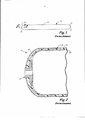
As FIGS. 1 e 2 ilustram um vaso de pressão alongado 10, tal como este revelado na Patente US 5.476.189, a qual é incorporada por referência neste documento. O vaso 10 possui uma seção de corpo principal 12 com as seções de extremidade 14. Uma bossa 16, tipicamente construída de alumínio, é proporcionada em uma ou em ambas as extremidade do vaso 10 para proporcionar uma abertura para comunicação com o interior do vaso 10.0 vaso 10 é formado a partir de um revestimento de polímero interno 20 coberto por uma carcaça externa composta 18. Neste caso, “composta” significa um material de matriz de resina reforçado com fibra tal como um filamento enrolado ou estrutura laminada. A carcaça composta 18 resolve todas as cargas estruturais e o revestimento 20 proporciona uma barreira para gás.FIGS. 1 and 2 illustrate an
Quando um vaso de pressão é exposto ao calor intenso, como no caso de um incêndio, o calor aumenta a pressão do gás no vaso. Em um típico vaso de aço, um ou mais discos de ruptura são proporcionados em um corpo de válvula na abertura de extremidade do vaso. Estes discos reagem ao aumento de pressão para liberar gás antes que o tanque rompa.When a pressure vessel is exposed to intense heat, as in the case of a fire, the heat increases the pressure of the gas in the vessel. In a typical steel vessel, one or more rupture discs are provided in a valve body at the end opening of the vessel. These discs react to the pressure increase to release gas before the tank ruptures.
Entretanto, no caso de um vaso composto, o composto não aquece como o aço e assim, a pressão não sobe no tanque da mesma maneira (de modo que uma válvula de alívio de pressão atuada por um aumento não pressão não é apropriada). Entretanto, quando da exposição continuada ao calor, a pressão no vaso composto aumenta, finalmente causando uma ruptura, desse modo resultando em uma liberação descontrolada de gás e/ou em uma explosão.However, in the case of a composite vessel, the compound does not heat up like steel and so the pressure does not rise in the tank in the same way (so a pressure relief valve actuated by a non-pressure increase is not appropriate). However, upon continued exposure to heat, the pressure in the composite vessel increases, ultimately causing a burst, thereby resulting in an uncontrolled release of gas and / or an explosion.
Na técnica anterior, vários sensores de temperatura são posicionados em localizações separadas ao longo de um tanque. Tais sensores são acoplados de forma operável com uma ou mais válvulas de alívio de pressão para o tanque. Tal acoplamento pode ser realizado eletricamente, quimicamente, mecanicamente, ou por uma linha pressurizada. Em um exemplo, vários sensores separados são fixados em uma tubulação pressurizada que passa ao longo do exterior do tanque. Entretanto, algumas autoridades regulando o transporte de certas mercadorias (por exemplo, gás em alta pressão) desaconselham o uso de linhas ou tubos de distribuição que são pressurizados durante o transporte. Além disso, o uso de sensores posicionados em localizações separadas em um tanque deixa partes do tanque que ficam sem a cobertura do sensor.In the prior art, several temperature sensors are positioned at separate locations along a tank. Such sensors are operably coupled with one or more pressure relief valves for the tank. Such coupling can be carried out electrically, chemically, mechanically, or by a pressurized line. In one example, several separate sensors are attached to a pressurized pipe that runs along the outside of the tank. However, some authorities regulating the transport of certain goods (for example, high pressure gas) advise against the use of distribution lines or tubes that are pressurized during transport. In addition, the use of sensors positioned in separate locations in a tank leaves parts of the tank that are left without the sensor cover.
Esta revelação descreve um aparelho compreendendo uma válvula e um elemento de liga de memória de forma. A válvula compreende uma alavanca em uma primeira posição, por meio da qual a válvula é fechada. O elemento de liga de memória de forma possui uma primeira extremidade conectada com a alavanca. O elemento de liga de memória de forma foi estendido para ter um primeiro comprimento, onde a exposição de pelo menos uma parte do elemento de liga de memória de forma à uma temperatura maior ou igual a sua temperatura de transformação de austenita faz com que o elemento de liga de memória de forma encurte para um segundo comprimento, o segundo comprimento sendo menor do que o primeiro comprimento, fazendo com que, desse modo, a primeira extremidade do e- lemento de liga de memória de forma puxe a alavanca para uma segunda posição, por meio da qual a válvula é aberta.This disclosure describes an apparatus comprising a valve and a shape memory alloy element. The valve comprises a lever in a first position, by means of which the valve is closed. The shape memory alloy element has a first end connected with the lever. The shape memory alloy element has been extended to have a first length, where the exposure of at least a part of the memory alloy element to a temperature greater than or equal to its austenite transformation temperature causes the element memory alloy shorten to a second length, the second length being less than the first length, thereby causing the first end of the memory alloy element to pull the lever to a second position , through which the valve is opened.
Este sumário é proporcionado para introduzir conceitos de forma simplificada, os quais são adicionalmente descritos baixo na Descrição Detalhada. Este sumário não é pretendido para identificar aspectos chave ou aspectos essenciais do assunto revelado ou reivindicado e não é pretendido para descrever cada concretização revelada ou cada implementação do assunto revelado ou reivindicado. Especificamente os aspectos revelados neste documento com respeito a uma concretização podem ser igualmente aplicáveis para outra. Adicionalmente, este sumário não é pretendido para ser utilizado como um auxílio ao se determinar o escopo do assunto reivindicado. Várias outras novas vantagens, aspectos e relações irão se tornar aparentes à medida que esta descrição continuar. As figuras e a descrição a seguir exemplificam mais particularmente concretizações ilustrativas.This summary is provided to introduce concepts in a simplified way, which are further described below in the Detailed Description. This summary is not intended to identify key or essential aspects of the revealed or claimed subject and is not intended to describe each revealed embodiment or each implementation of the revealed or claimed subject. Specifically, the aspects disclosed in this document with respect to one embodiment may be equally applicable to another. In addition, this summary is not intended to be used as an aid in determining the scope of the claimed subject. Several other new advantages, aspects and relationships will become apparent as this description continues. The following figures and description more particularly illustrate illustrative embodiments.
O assunto revelado será adicionalmente explicado com referência às figuras ane- xas, onde estruturas ou elementos do sistema iguais são referidos por números de referência iguais por todas as várias vistas.The subject revealed will be further explained with reference to the attached figures, where the same structures or elements of the system are referred to by the same reference numbers for all the various views.
A FIG. 1 é uma vista em elevação lateral de um típico vaso de pressão alongado.FIG. 1 is a side elevation view of a typical elongated pressure vessel.
A FIG. 2 é uma vista parcial em seção transversal através de uma extremidade de tal vaso de pressão, pega ao longo da linha 2-2 da FIG. 1.FIG. 2 is a partial cross-sectional view through one end of such a pressure vessel, taken along line 2-2 of FIG. 1.
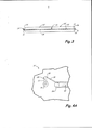
A FIG. 3 é uma vista em elevação lateral de um vaso de pressão alongado incorporando um gatilho de liga de memória de formato para uma válvula de alívio de pressão da presente revelação.FIG. 3 is a side elevation view of an elongated pressure vessel incorporating a shaped memory alloy trigger for a pressure relief valve of the present disclosure.
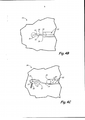
A FIG. 4A é uma vista esquemática de uma parte de uma seção de extremidade do vaso de pressão da FIG. 3, com a válvula de alívio de pressão em uma posição fechada.FIG. 4A is a schematic view of part of a pressure vessel end section of FIG. 3, with the pressure relief valve in a closed position.
A FIG. 4B é uma vista esquemática de uma parte de uma seção de extremidade do vaso de pressão da FIG. 3, com a válvula de alívio de pressão em uma primeira posição aberta.FIG. 4B is a schematic view of part of a pressure vessel end section of FIG. 3, with the pressure relief valve in a first open position.
A FIG. 4C é uma vista esquemática de uma parte de uma seção de extremidade do vaso de pressão da FIG. 3, com a válvula de alívio de pressão em uma segunda posição aberta.FIG. 4C is a schematic view of part of a pressure vessel end section of FIG. 3, with the pressure relief valve in a second open position.
A FIG. 5 é uma vista em elevação lateral de um vaso de pressão alongado incorporando um gatilho de liga de memória de forma conectado com uma válvula de alívio de pressão em cada extremidade do vaso.FIG. 5 is a side elevation view of an elongated pressure vessel incorporating a memory alloy trigger so connected with a pressure relief valve at each end of the vessel.
Enquanto as figuras identificadas acima expõem uma ou mais concretizações do assunto revelado, outras concretizações também são contempladas, como citado na revelação. Em todos os casos, esta revelação apresenta o assunto revelado por meio de representação e não de limitação. Deve ser entendido que várias outras modificações e concretizações podem ser imaginadas pelos versados na técnica, as quais se situam dentro do escopo e do espírito dos princípios desta revelação.While the figures identified above expose one or more embodiments of the revealed subject, other embodiments are also contemplated, as mentioned in the revelation. In all cases, this disclosure presents the subject revealed through representation and not limitation. It should be understood that several other modifications and embodiments can be imagined by those skilled in the art, which fall within the scope and spirit of the principles of this revelation.
As figuras podem não ser desenhadas em escala. Em particular, alguns aspectos podem ser aumentados em relação a outros aspectos para clareza. Além disso, onde os termos tais como acima, abaixo, sobre, sob, de cima, de baixo, lateral, direita, esquerda, vertical, horizontal, etc., são utilizados, é para ser entendido que eles são utilizados somente para facilidade de entendimento da descrição. É contemplado que as estruturas possam ser orientadas de outro modo.Figures may not be drawn to scale. In particular, some aspects can be increased in relation to other aspects for clarity. In addition, where terms such as above, below, over, under, above, below, side, right, left, vertical, horizontal, etc., are used, it is to be understood that they are used only for ease of understanding of the description. It is contemplated that the structures can be oriented in another way.
Esta revelação proporciona uma montagem de válvula e sensor para despressurização controlada de um vaso de pressão, tal como um vaso cilíndrico composto de armazenamento de gás, em particular, quando o vaso é exposto a um incêndio. A presente revelação proporciona uma montagem de válvula e sensor ativada por temperatura 21 para liberar gás a partir de dentro do vaso, ao invés do que aliviar o gás em excesso utilizando uma vál- villa baseada na pressão. Como ilustrado na FIG. 3, um pedaço de tubulação 22 é montado no exterior do vaso de pressão 10’ para passar ao longo do comprimento do vaso 10’. Em uma concretização ilustrativa, a tubulação 22 é fabricada de aço inoxidável e possui um diâmetro externo de 0,635 centímetros (0,25 polegadas). Em uma concretização ilustrativa, a tubulação 22 possui as perfurações 40 (apresentadas na FIG. 4C) para permitir fluxo livre de calor dentro da tubulação 22. A válvula de alívio ou de liberação de pressão (PRV) 24 é montada na bossa 16’ próxima da primeira extremidade da tubulação 22 (veja a FIG. 4A).This disclosure provides a valve and sensor assembly for controlled depressurization of a pressure vessel, such as a cylindrical vessel composed of gas storage, in particular, when the vessel is exposed to a fire. The present disclosure provides a temperature-activated valve and sensor assembly 21 to release gas from inside the vessel, rather than relieving excess gas using a pressure-based valve. As illustrated in FIG. 3, a piece of
Um elemento de liga de memória de forma (SMA), tal como o arame 28, é “ajustado” por deformação (estiramento do arame 2) aproximadamente 10%. Esta deformação é obtida em uma temperatura abaixo da temperatura de partida da austenita da SMA. O arame estendido 28 roscado dentro da tubulação 22, a qual é fixa em relação à alavanca 32 da PRV 24. Uma primeira extremidade 30 do arame 28 é conectada com a alavanca 32 da PRV 24. Uma segunda extremidade 34 do arame 28 é fixada em relação à tubulação 22, tal como por ser conectada com uma segunda extremidade 36 da tubulação 22 (tal como por um prendedor mecânico ou por forjamento da segunda extremidade 36 da tubulação 22 sobre a segunda extremidade 34 do arame 28). Em uma concretização ilustrativa, a segunda extremidade 34 do arame 28 é posicionada fixa em relação ao vaso de pressão 10’.A shape memory alloy (SMA) element, such as
Em uma concretização ilustrativa, a PRV 24 é uma válvula de um quarto de volta convencional. A FIG. 4A apresenta a PRV 24 em uma posição fechada, onde a alavanca 32 está em uma posição vertical. Com tal válvula de um quarto de volta convencional, girar a alavanca 32 cerca de noventa graus (até as posições apresentadas nas FIGS. 4B ou 4C) abre a válvula, desse modo permitindo ao gás escapar a partir da bossa 16’.In an illustrative embodiment, the PRV 24 is a conventional quarter-turn valve. FIG. 4A shows PRV 24 in a closed position, where
Em uma concretização ilustrativa, o aquecimento do arame 28 maior ou igual a sua temperatura de transformação de austenita faz com que o arame 28 retraia por 6 até 8%. Assim, para cada pé de arame transformado, a deformação recuperada pelo arame 28 causa que o mesmo encurte por 1,8288 até 2,4384 centímetros (0,72 até 0,96 polegadas). À medida que ele encurta, a primeira extremidade 30 puxa com uma força de aproximadamente 54,432 kg (120 libras) (para um diâmetro de arame de 0,1524 centímetros (0,06 polegadas)) e desse modo gira a alavanca 32 para abrir a PRV 24. Em uma concretização ilustrativa, o gatilho revelado é projetado de modo que a exposição de uma parte requerida do vaso 10’ além ou à temperatura de transformação do arame 28 causa um encurtamento do arame 28 que é adequado para puxar a alavanca 32 até a posição aberta ilustrada na FIG. 4B. Em uma concretização ilustrativa, a PRV 24 é projetada para ativação com um encolhimento total do arame 28 de 2,54 centímetros (1 polegada). Enquanto a extremidade 30 do arame 28 é conectada com uma extremidade da alavanca 32 nas concretizações ilustradas, o arame 28 pode ser conectado com a alavanca 32 em outra localização, como apropriado para uma aplicação particular, levando em consideração a força de deslocamento e de tração requerida para abrir a PRV 24.In an illustrative embodiment,
O calor para ativar a montagem de sensor e válvula 21 pode estar presente em qualquer lugar ao longo do comprimento do arame SMA 28. Em uma concretização ilustrativa, o arame SMA 28 é passado em uma linha substancialmente reta paralela à superfície do vaso ao longo de substancialmente todo o comprimento do vaso 10’, desse modo protegendo o vaso de pressão 10’ através de todo o seu comprimento. Em outras concretizações, a tubulação 22 e o arame 28 podem passar em localizações adicionais onde um incêndio ou temperatura elevada podem ser detectados. Se qualquer parte do arame 28 for aquecida passando de uma temperatura estabilizada, o arame irá contrair até certo grau. Se uma parte suficiente do arame 28 contrair, o movimento da extremidade 30 do arame 20 puxa a alavanca 32 para abrir a PRV 24. Com a PRV 24 desse modo aberta, o gás pressurizado a partir de dentro do vaso 10’ pode escapar através da PRV aberta 24 de uma maneira controlada.The heat to activate the sensor and valve assembly 21 can be present anywhere along the length of the
Por consequência, o arame SMA 28 atua como um sensor de temperatura ao longo de todo o comprimento do vaso 10’ e pode assim reagira incêndios localizados para permitir a liberação de gás a partir do vaso 10’. A disposição de gatilho revelada pode ser utilizada para proteger um vaso de qualquer comprimento, mesmo vasos de pressão muito grandes. Mais do que uma tubulação 22 e arame 28 podem ser utilizados em uma única válvula 24. A tubulação 22 e o arame 28 não estão limitados aos formatos retos, mas podem ser curvos, contanto que o arame 28 seja móvel dentro da tubulação 22. Por exemplo, o arame SMA 28 colocado em uma configuração espiral a partir de uma extremidade do tanque até a outra oferece proteção em todos os lados do tanque bem como proteção para o comprimento do tanque. A tubulação 22 protege o arame sensor 28 de condições ambientais que podem afetar de forma adversa sua performance. Esta disposição resulta em uma montagem de sensor 21 relativamente barata. A montagem de sensor 21 revelada minimiza ativação falsa, desde que a PRV 24 somente pode ser ativada quando o arame 28 é exposto a uma temperatura que excede a temperatura de formação de austenita. A temperatura de transformação é determinada pela composição da liga do arame. Em uma concretização ilustrativa, a liga é 54,79 por cento de peso Níquei e 45,21 por cento de peso de Titânio e possui uma temperatura de transformação de 100° C (212 F°). A quantidade de força pode ser controlada pela seleção da área de seção transversal (por exemplo, diâmetro) do elemento ou arame de memória de forma 28. Um arame ilustrativo possuindo um diâmetro de 0,1524 centímetros (0,06 polegadas) produz aproximadamente 54,432 kg (120 libras) de tração uma vez que a temperatura ambiente exceda a temperatura de transformação da liga particular. Mais força é obtida com um arame possuindo uma área de seção transversal maior. A força desenvolvida é essencialmente independente do comprimento e da temperatura; assim, maiores temperaturas ou maior fornecimento de calor não.irá significativamente aumentar ou diminuir a força desenvolvida devido à transformação. Uma vez que a montagem de sensor 21 seja colocada no lugar, ela fica essencialmente livre de manutenção durante a vida útil do vaso de pressão 10’. O arame de memória de forma 28 essencialmente não fica sob pressão até que a transformação ocorra.Consequently, the
O dispositivo de liberação de pressão também pode ser configurado para ser ativado se o arame 28 for partido. Em uma concretização ilustrativa, a alavanca 32 é tendida (tal como pela mola 38) na direção apresentada na FIG. 4C, a qual é deslocada a partir da posição “desativada” da FIG. 4A por um ângulo de rotação de ao redor de 90 graus (na direção oposta ao deslocamento entre as posições “desativada” e “ativada” apresentadas nas FIGS. 4A e 4B, respectivamente). Assim, se o arame 28 for partido e não mais exercer uma força de tração sobre a alavanca 32, a alavanca 32 automaticamente salta para a posição ilustrada na FIG. 4C, desse modo abrindo a PRV 24.The pressure release device can also be configured to activate if
Em outra concretização ilustrativa, ilustrada na FIG. 5, a segunda extremidade 34 do arame 28 é conectada com a alavanca de uma segunda PRV. Isto permitiria que duas PRVs fossem ativadas, ventilando o vaso 10’ a partir de ambas as extremidades 14’. Ainda em outra concretização, a montagem revelada de tubulação, de válvula SMA e de sensor 21 pode ser utilizada para atuar qualquer dispositivo (não apenas uma PRV) tal como, por e- xemplo, um sistema de combate a incêndio.In another illustrative embodiment, illustrated in FIG. 5, the second end 34 of the
Apesar do assunto desta revelação ter sido descrito com referência as várias concretizações, os versados na técnica irão reconhecer que alterações podem ser feitas na forma e nos detalhes sem afastamento do espírito e do escopo da revelação. Em adição, qualquer aspecto revelado com respeito a uma concretização pode ser incorporado em outra concretização, e vice-versa.Although the subject of this revelation has been described with reference to the various embodiments, those skilled in the art will recognize that changes can be made to the form and details without departing from the spirit and scope of the revelation. In addition, any aspect disclosed with respect to one embodiment can be incorporated into another embodiment, and vice versa.
Claims (13)
Applications Claiming Priority (3)
| Application Number | Priority Date | Filing Date | Title |
|---|---|---|---|
| US15690009P | 2009-03-03 | 2009-03-03 | |
| US61/156.900 | 2009-03-03 | ||
| PCT/US2010/026009 WO2010101976A1 (en) | 2009-03-03 | 2010-03-03 | Shape memory alloy trigger for pressure relief valve |
Publications (2)
| Publication Number | Publication Date |
|---|---|
| BRPI1007868A2 BRPI1007868A2 (en) | 2018-02-14 |
| BRPI1007868B1 true BRPI1007868B1 (en) | 2020-09-15 |
Family
ID=42174642
Family Applications (1)
| Application Number | Title | Priority Date | Filing Date |
|---|---|---|---|
| BRPI1007868-1A BRPI1007868B1 (en) | 2009-03-03 | 2010-03-03 | APPLIANCE UNDERSTANDING SHAPE MEMORY ALLOY TRIGGER FOR PRESSURE RELIEF VALVE |
Country Status (11)
| Country | Link |
|---|---|
| US (1) | US8820069B2 (en) |
| EP (1) | EP2404090B1 (en) |
| JP (1) | JP5738776B2 (en) |
| KR (1) | KR101501048B1 (en) |
| CN (1) | CN102341630B (en) |
| AU (1) | AU2010221443B2 (en) |
| BR (1) | BRPI1007868B1 (en) |
| CA (1) | CA2753386C (en) |
| ES (1) | ES2547280T3 (en) |
| RU (1) | RU2500943C2 (en) |
| WO (1) | WO2010101976A1 (en) |
Families Citing this family (25)
| Publication number | Priority date | Publication date | Assignee | Title |
|---|---|---|---|---|
| US8720722B2 (en) * | 2005-12-15 | 2014-05-13 | Cornerstone Research Group, Inc. | Venting mechanism for containers |
| US10226991B2 (en) * | 2009-10-28 | 2019-03-12 | GM Global Technology Operations LLC | Air curtain using smart materials |
| DE102011001140A1 (en) * | 2011-03-08 | 2012-09-13 | Thyssenkrupp Steel Europe Ag | Flat steel product, method for producing a flat steel product and method for producing a component |
| US10407760B2 (en) * | 2011-09-30 | 2019-09-10 | Nippon Steel Corporation | Hot-dip galvanized steel sheet and manufacturing method thereof |
| DE112013006786T5 (en) | 2013-03-06 | 2015-12-03 | Kongsberg Automotive Ab | Fluid flow path adjustment device with a shape memory alloy element |
| US9097358B2 (en) * | 2013-05-01 | 2015-08-04 | Emcara Gas Development Inc. | Valve with temperature activated trigger having novel material configuration |
| DE112013007682T5 (en) | 2013-12-13 | 2016-09-22 | Kongsberg Automotive Ab | SMA valve for controlling the supply of air to an air cell in a vehicle seat |
| CN105829164B (en) | 2013-12-13 | 2019-01-18 | 康斯博格汽车股份公司 | For controlling the SMA valve to the Pressurized air supply of air element in vehicle seat |
| CN105813887B (en) | 2013-12-13 | 2017-11-10 | 康斯博格汽车股份公司 | For controlling the SMA valves to the Pressurized air supply of air element in seat |
| DE102014000616A1 (en) | 2014-01-18 | 2015-07-23 | Daimler Ag | Thermally triggered safety valve |
| DE112014006722T5 (en) | 2014-06-04 | 2017-03-02 | Kongsberg Automotive Ab | SMA valve for controlling the supply of compressed air to an air cell in a vehicle seat |
| CN104197188B (en) * | 2014-08-25 | 2017-02-01 | 上海宇航系统工程研究所 | Gas jetting device driven by shape memory alloy wires |
| GB2531265A (en) * | 2014-10-13 | 2016-04-20 | Graviner Ltd Kidde | A frangible plug for use in a valve mechanism |
| US9416878B1 (en) | 2015-02-16 | 2016-08-16 | Kongsberg Automotive, Inc. | Valve including a shape memory alloy member |
| NO20150851A1 (en) * | 2015-07-01 | 2016-09-12 | Techinvent As | An apparatus for controlling a fluid flow |
| CN108730604A (en) * | 2017-04-14 | 2018-11-02 | 国家电力投资集团公司 | Passive valve system |
| CN107327692A (en) * | 2017-07-17 | 2017-11-07 | 凯迈(洛阳)气源有限公司 | A kind of aircraft gas cylinder |
| EP3672823B1 (en) | 2017-09-14 | 2023-07-19 | Agility Fuel Systems LLC | Systems for monitoring volatile fuel system components |
| US10942533B2 (en) | 2018-02-14 | 2021-03-09 | Hexagon Technology As | System for multiple pressure relief device activation |
| EP3903017B1 (en) * | 2019-03-12 | 2023-03-22 | Nikola Corporation | Pressurized vessel heat shield and thermal pressure relief system |
| KR102187342B1 (en) | 2019-09-03 | 2020-12-04 | (주)삼익브리즈 | Relief valve for preventing frost |
| EP4031799A4 (en) | 2019-11-25 | 2023-10-25 | Agility Fuel Systems LLC | Improved pressure relief device |
| CN113124247B (en) * | 2021-04-30 | 2022-05-20 | 中国工程物理研究院机械制造工艺研究所 | Pipeline sealing structure capable of realizing high-temperature air leakage safety protection, pipeline sealing and high-temperature air leakage method |
| CN113431915B (en) * | 2021-07-02 | 2023-01-24 | 威海观复燃气安全科技有限公司 | Liquefied petroleum gas self-closing valve |
| CN114877111B (en) * | 2022-07-12 | 2022-12-09 | 山东拙诚智能科技有限公司 | Gas safety control device |
Family Cites Families (49)
| Publication number | Priority date | Publication date | Assignee | Title |
|---|---|---|---|---|
| FR1115990A (en) * | 1953-11-16 | 1956-05-02 | Gen Motors Corp | Advanced refrigerator |
| US3489309A (en) | 1966-12-13 | 1970-01-13 | Foster Wheeler Corp | Pressure vessels |
| US3613732A (en) | 1969-07-17 | 1971-10-19 | Robertshaw Controls Co | Temperature-responsive valve operators |
| US3914991A (en) | 1973-07-24 | 1975-10-28 | Nasa | Strain gage mounting assembly |
| DE2728651C2 (en) | 1977-06-24 | 1981-09-17 | Siempelkamp Gießerei GmbH & Co, 4150 Krefeld | Method for monitoring a cylindrical nuclear reactor pressure vessel and devices for carrying out such a method |
| US4284235A (en) * | 1979-12-19 | 1981-08-18 | Werner Diermayer | Vent control arrangement for combustion apparatus |
| JPS5874666U (en) * | 1981-11-13 | 1983-05-20 | 東北金属工業株式会社 | temperature sensitive valve |
| JPS58132273A (en) * | 1982-02-02 | 1983-08-06 | 日本電信電話株式会社 | Flexible dispersion type el matrix display element |
| JPS58132273U (en) * | 1982-03-03 | 1983-09-06 | 奥原 克美 | Gas leak prevention device |
| US4570851A (en) | 1984-05-07 | 1986-02-18 | Cirillo John R | Temperature regulating, pressure relief flow valves employing shaped memory alloys |
| JPS61121341A (en) | 1984-11-16 | 1986-06-09 | Mitsubishi Electric Corp | Manufacture of glass passivation type semiconductor device |
| JPS61121341U (en) * | 1985-01-16 | 1986-07-31 | ||
| US4840346A (en) * | 1985-04-11 | 1989-06-20 | Memory Metals, Inc. | Apparatus for sealing a well blowout |
| US4884780A (en) * | 1985-04-26 | 1989-12-05 | Nissan Motor Company, Limited | Valve actuating arrangement |
| JPS61183417U (en) * | 1985-05-07 | 1986-11-15 | ||
| JPS62129487A (en) * | 1985-11-30 | 1987-06-11 | 大同特殊鋼株式会社 | Opening and closing drive apparatus of opening and closing panel |
| US4699314A (en) * | 1986-12-17 | 1987-10-13 | Carrier Corporation | Actuator for a heating/cooling diffuser |
| JPS63162265A (en) * | 1986-12-26 | 1988-07-05 | Canon Inc | Printer |
| JPS63162265U (en) * | 1987-04-08 | 1988-10-24 | ||
| US4965545A (en) * | 1989-08-09 | 1990-10-23 | Tini Alloy Company | Shape memory alloy rotary actuator |
| US4973024A (en) * | 1989-09-26 | 1990-11-27 | Toki Corporation Kabushiki Kaisha | Valve driven by shape memory alloy |
| US5277028A (en) | 1990-03-26 | 1994-01-11 | Mercedes-Benz Ag | Hydraulic flow control with temperature sensitive spring biased bypass valve |
| US5211371A (en) * | 1991-07-22 | 1993-05-18 | Advanced Control Technologies, Inc. | Linearly actuated valve |
| US5165450A (en) * | 1991-12-23 | 1992-11-24 | Texaco Inc. | Means for separating a fluid stream into two separate streams |
| GB2272276B (en) * | 1992-11-06 | 1995-03-29 | Kim San Toh | Improvements in LPG cylinders |
| US5476189A (en) | 1993-12-03 | 1995-12-19 | Duvall; Paul F. | Pressure vessel with damage mitigating system |
| US5522428A (en) | 1994-08-29 | 1996-06-04 | Duvall; Paul F. | Natural gas vehicle tank life sensor and control |
| US5518140A (en) | 1994-11-07 | 1996-05-21 | Cryenco, Inc. | Liquified gas storage tank overfill protection system and method |
| US5462226A (en) * | 1994-11-07 | 1995-10-31 | Itt Corporation | Temperature-responsive, locking mechanism for, and in combination with, a fluid valve |
| US5586722A (en) | 1995-05-05 | 1996-12-24 | Murray; Jerome L. | Temperature and flow control valve |
| US5662139A (en) * | 1995-09-08 | 1997-09-02 | Lish; Dennis N. | Pressure relief valve with lockout position |
| US5788212A (en) | 1996-07-26 | 1998-08-04 | Gas Research Institute | Pressure relief device with shaped memory alloy thermally activated trigger |
| US5865418A (en) * | 1996-11-08 | 1999-02-02 | Matsushita Electric Works, Ltd. | Flow control valve |
| US6269830B1 (en) | 1998-09-28 | 2001-08-07 | Gas Research Institute | Extended area thermal activation device |
| JP3065038U (en) * | 1999-04-22 | 2000-01-28 | 國弘 主税 | Automatic opening device for fire extinguisher cylinders using the contraction force of shape memory alloy |
| FR2796701B1 (en) * | 1999-07-22 | 2001-09-07 | Giat Ind Sa | SAFETY VALVE FOR A SEALED ENCLOSURE CONTAINING A PRESSURE FLUID SUCH AS AN LPG TANK |
| RU2188683C1 (en) * | 2000-12-28 | 2002-09-10 | Сильянов Виталий Анатольевич | Fire extinguisher |
| WO2002057627A1 (en) * | 2001-01-17 | 2002-07-25 | M 2 Medical A/S | Shape memory alloy actuator |
| ATE301261T1 (en) | 2001-05-08 | 2005-08-15 | Alberto Arena | PROPORTIONAL VALVE WITH A SHAPE MEMORY ALLOY ACTUATOR |
| ITTO20010618A1 (en) * | 2001-06-27 | 2002-12-27 | Fiat Ricerche | FLEXIBLE CABLE ACTUATOR DEVICE INCORPORATING A SHAPE MEMORY ELEMENT. |
| CN1685150A (en) * | 2002-07-24 | 2005-10-19 | M2医药有限公司 | Shape memory alloy actuator |
| US6955187B1 (en) * | 2003-07-16 | 2005-10-18 | Tini Alloy Company | Zinc-air battery control valve |
| ITTO20030553A1 (en) * | 2003-07-17 | 2005-01-18 | Fiat Ricerche | FLUIDO FLOW CONTROL DEVICE |
| WO2005026592A2 (en) * | 2003-09-05 | 2005-03-24 | Alfmeier Präzision AG Baugruppen und Systemlösungen | A system, method and apparatus for reducing frictional forces and for compensating shape memory alloy-actuated valves and valve systems at high temperatures |
| US20080148853A1 (en) | 2003-09-22 | 2008-06-26 | Hyeung-Yun Kim | Gas tank having usage monitoring system |
| DE102004062241A1 (en) * | 2004-12-23 | 2006-07-13 | BSH Bosch und Siemens Hausgeräte GmbH | Actuator for valves |
| KR100966945B1 (en) * | 2005-07-26 | 2010-06-30 | 파나소닉 전공 주식회사 | Compact valve |
| US20080319688A1 (en) | 2007-02-26 | 2008-12-25 | Hyeung-Yun Kim | Usage monitoring system of gas tank |
| US8499779B2 (en) * | 2008-01-16 | 2013-08-06 | The United States Of America As Represented By The Administrator Of The National Aeronautics Space Administration | Systems, methods and apparatus of a nitinol valve |
-
2010
- 2010-03-03 RU RU2011139966/06A patent/RU2500943C2/en active
- 2010-03-03 KR KR1020117022777A patent/KR101501048B1/en active IP Right Grant
- 2010-03-03 JP JP2011553064A patent/JP5738776B2/en active Active
- 2010-03-03 CN CN2010800102698A patent/CN102341630B/en not_active Expired - Fee Related
- 2010-03-03 AU AU2010221443A patent/AU2010221443B2/en not_active Ceased
- 2010-03-03 EP EP10707757.0A patent/EP2404090B1/en active Active
- 2010-03-03 WO PCT/US2010/026009 patent/WO2010101976A1/en active Application Filing
- 2010-03-03 ES ES10707757.0T patent/ES2547280T3/en active Active
- 2010-03-03 BR BRPI1007868-1A patent/BRPI1007868B1/en not_active IP Right Cessation
- 2010-03-03 US US13/254,346 patent/US8820069B2/en active Active
- 2010-03-03 CA CA2753386A patent/CA2753386C/en active Active
Also Published As
| Publication number | Publication date |
|---|---|
| BRPI1007868A2 (en) | 2018-02-14 |
| EP2404090A1 (en) | 2012-01-11 |
| US8820069B2 (en) | 2014-09-02 |
| RU2500943C2 (en) | 2013-12-10 |
| AU2010221443B2 (en) | 2014-11-27 |
| CA2753386A1 (en) | 2010-09-10 |
| ES2547280T3 (en) | 2015-10-02 |
| JP5738776B2 (en) | 2015-06-24 |
| WO2010101976A1 (en) | 2010-09-10 |
| RU2011139966A (en) | 2013-04-10 |
| KR20110128321A (en) | 2011-11-29 |
| CN102341630A (en) | 2012-02-01 |
| CA2753386C (en) | 2015-08-11 |
| JP2012519816A (en) | 2012-08-30 |
| CN102341630B (en) | 2013-09-18 |
| KR101501048B1 (en) | 2015-03-10 |
| US20120011843A1 (en) | 2012-01-19 |
| AU2010221443A1 (en) | 2011-09-08 |
| EP2404090B1 (en) | 2015-07-15 |
Similar Documents
| Publication | Publication Date | Title |
|---|---|---|
| BRPI1007868B1 (en) | APPLIANCE UNDERSTANDING SHAPE MEMORY ALLOY TRIGGER FOR PRESSURE RELIEF VALVE | |
| ES2209192T3 (en) | PIPE SYSTEM RESISTANT TO CORROSION AND FIRE. | |
| ES2215883T3 (en) | PRESSURE DEPOSIT TO STORE LIQUID AND / OR GASEOUS MEDIA UNDER PRESSURE, CONSISTING IN A PLASTIC NUCLEUS TANK REINFORCED WITH FIBER REINFORCED PLASTICS AND PROCEDURE FOR MANUFACTURING. | |
| ES2425238T3 (en) | Flexible tube axially reinforced | |
| ES2945691T3 (en) | Metal-lined pressure vessel comprising a pole projection | |
| ES2347892T3 (en) | DEPOSIT FOR HIGH PRESSURE FLUIDS. | |
| BRPI1009280B1 (en) | riser clamp | |
| ES2956067T3 (en) | Inline Cycle Fuse | |
| ES2755180T3 (en) | Reinforced concrete pipe | |
| BR112013030279B1 (en) | dry extinguisher head | |
| BRPI0710427A2 (en) | hose and method of fabricating a hose | |
| BR112018068782B1 (en) | APPARATUS FOR PRESSURE VESSEL, PRESSURE VESSEL AND METHOD FOR FORMING A PRESSURE VESSEL | |
| BRPI0810573B1 (en) | flexible tubular pipeline for the transport of gaseous hydrocarbons in the field of offshore oil exploration | |
| BRPI0621637A2 (en) | butterfly valve, container and valve assembly, and method for holding a plastic valve and a flexible container | |
| FI101860B (en) | Arrangement with anesthetic evaporator | |
| BRPI0910880B1 (en) | composite hose, and method for producing a composite hose | |
| BR102016020464B1 (en) | METHOD FOR MANUFACTURING A DOUBLE WALL TUBE SEGMENT | |
| NO844228L (en) | FLEXIBLE PIPE PIPE, SPECIAL FOR THE OIL INDUSTRY | |
| MX2007014471A (en) | Temperature and pressure relief apparatus for water heater. | |
| BR112020009784A2 (en) | an internal safety device, a liquefied fuel gas system, and a vehicle | |
| JP2006046486A (en) | Freezing preventing structure for level detection pipe | |
| NO300471B1 (en) | Flexible piping | |
| BR112018015311B1 (en) | flexible line | |
| WO2022232794A1 (en) | Pressure control device | |
| PT83158B (en) | CLOSING DEVICE FOR METAL FUSION SUSCEPTIVEL TO CONTROL THE PRESSURE OF GASES |
Legal Events
| Date | Code | Title | Description |
|---|---|---|---|
| B06F | Objections, documents and/or translations needed after an examination request according [chapter 6.6 patent gazette] | ||
| B06U | Preliminary requirement: requests with searches performed by other patent offices: procedure suspended [chapter 6.21 patent gazette] | ||
| B06A | Patent application procedure suspended [chapter 6.1 patent gazette] | ||
| B09A | Decision: intention to grant [chapter 9.1 patent gazette] | ||
| B16A | Patent or certificate of addition of invention granted [chapter 16.1 patent gazette] |
Free format text: PRAZO DE VALIDADE: 10 (DEZ) ANOS CONTADOS A PARTIR DE 15/09/2020, OBSERVADAS AS CONDICOES LEGAIS. |
|
| B21F | Lapse acc. art. 78, item iv - on non-payment of the annual fees in time |
Free format text: REFERENTE A 14A ANUIDADE. |
|
| B24J | Lapse because of non-payment of annual fees (definitively: art 78 iv lpi, resolution 113/2013 art. 12) |
Free format text: EM VIRTUDE DA EXTINCAO PUBLICADA NA RPI 2764 DE 26-12-2023 E CONSIDERANDO AUSENCIA DE MANIFESTACAO DENTRO DOS PRAZOS LEGAIS, INFORMO QUE CABE SER MANTIDA A EXTINCAO DA PATENTE E SEUS CERTIFICADOS, CONFORME O DISPOSTO NO ARTIGO 12, DA RESOLUCAO 113/2013. |