EP2370306B1 - Control device for assisting the parking process - Google Patents
Control device for assisting the parking process Download PDFInfo
- Publication number
- EP2370306B1 EP2370306B1 EP09747803.6A EP09747803A EP2370306B1 EP 2370306 B1 EP2370306 B1 EP 2370306B1 EP 09747803 A EP09747803 A EP 09747803A EP 2370306 B1 EP2370306 B1 EP 2370306B1
- Authority
- EP
- European Patent Office
- Prior art keywords
- parking space
- vehicle
- parking
- boundary
- beyond
- Prior art date
- Legal status (The legal status is an assumption and is not a legal conclusion. Google has not performed a legal analysis and makes no representation as to the accuracy of the status listed.)
- Not-in-force
Links
Images


Classifications
-
- B—PERFORMING OPERATIONS; TRANSPORTING
- B62—LAND VEHICLES FOR TRAVELLING OTHERWISE THAN ON RAILS
- B62D—MOTOR VEHICLES; TRAILERS
- B62D15/00—Steering not otherwise provided for
- B62D15/02—Steering position indicators ; Steering position determination; Steering aids
- B62D15/027—Parking aids, e.g. instruction means
- B62D15/028—Guided parking by providing commands to the driver, e.g. acoustically or optically
-
- B—PERFORMING OPERATIONS; TRANSPORTING
- B62—LAND VEHICLES FOR TRAVELLING OTHERWISE THAN ON RAILS
- B62D—MOTOR VEHICLES; TRAILERS
- B62D15/00—Steering not otherwise provided for
- B62D15/02—Steering position indicators ; Steering position determination; Steering aids
- B62D15/027—Parking aids, e.g. instruction means
- B62D15/0285—Parking performed automatically
-
- G—PHYSICS
- G01—MEASURING; TESTING
- G01S—RADIO DIRECTION-FINDING; RADIO NAVIGATION; DETERMINING DISTANCE OR VELOCITY BY USE OF RADIO WAVES; LOCATING OR PRESENCE-DETECTING BY USE OF THE REFLECTION OR RERADIATION OF RADIO WAVES; ANALOGOUS ARRANGEMENTS USING OTHER WAVES
- G01S15/00—Systems using the reflection or reradiation of acoustic waves, e.g. sonar systems
- G01S15/88—Sonar systems specially adapted for specific applications
- G01S15/93—Sonar systems specially adapted for specific applications for anti-collision purposes
- G01S15/931—Sonar systems specially adapted for specific applications for anti-collision purposes of land vehicles
-
- G—PHYSICS
- G01—MEASURING; TESTING
- G01S—RADIO DIRECTION-FINDING; RADIO NAVIGATION; DETERMINING DISTANCE OR VELOCITY BY USE OF RADIO WAVES; LOCATING OR PRESENCE-DETECTING BY USE OF THE REFLECTION OR RERADIATION OF RADIO WAVES; ANALOGOUS ARRANGEMENTS USING OTHER WAVES
- G01S13/00—Systems using the reflection or reradiation of radio waves, e.g. radar systems; Analogous systems using reflection or reradiation of waves whose nature or wavelength is irrelevant or unspecified
- G01S13/88—Radar or analogous systems specially adapted for specific applications
- G01S13/93—Radar or analogous systems specially adapted for specific applications for anti-collision purposes
- G01S13/931—Radar or analogous systems specially adapted for specific applications for anti-collision purposes of land vehicles
- G01S2013/9314—Parking operations
-
- G—PHYSICS
- G01—MEASURING; TESTING
- G01S—RADIO DIRECTION-FINDING; RADIO NAVIGATION; DETERMINING DISTANCE OR VELOCITY BY USE OF RADIO WAVES; LOCATING OR PRESENCE-DETECTING BY USE OF THE REFLECTION OR RERADIATION OF RADIO WAVES; ANALOGOUS ARRANGEMENTS USING OTHER WAVES
- G01S15/00—Systems using the reflection or reradiation of acoustic waves, e.g. sonar systems
- G01S15/88—Sonar systems specially adapted for specific applications
- G01S15/93—Sonar systems specially adapted for specific applications for anti-collision purposes
- G01S15/931—Sonar systems specially adapted for specific applications for anti-collision purposes of land vehicles
- G01S2015/932—Sonar systems specially adapted for specific applications for anti-collision purposes of land vehicles for parking operations
- G01S2015/933—Sonar systems specially adapted for specific applications for anti-collision purposes of land vehicles for parking operations for measuring the dimensions of the parking space when driving past
- G01S2015/935—Sonar systems specially adapted for specific applications for anti-collision purposes of land vehicles for parking operations for measuring the dimensions of the parking space when driving past for measuring the contour, e.g. a trajectory of measurement points, representing the boundary of the parking space
-
- G—PHYSICS
- G01—MEASURING; TESTING
- G01S—RADIO DIRECTION-FINDING; RADIO NAVIGATION; DETERMINING DISTANCE OR VELOCITY BY USE OF RADIO WAVES; LOCATING OR PRESENCE-DETECTING BY USE OF THE REFLECTION OR RERADIATION OF RADIO WAVES; ANALOGOUS ARRANGEMENTS USING OTHER WAVES
- G01S15/00—Systems using the reflection or reradiation of acoustic waves, e.g. sonar systems
- G01S15/88—Sonar systems specially adapted for specific applications
- G01S15/93—Sonar systems specially adapted for specific applications for anti-collision purposes
- G01S15/931—Sonar systems specially adapted for specific applications for anti-collision purposes of land vehicles
- G01S2015/937—Sonar systems specially adapted for specific applications for anti-collision purposes of land vehicles sensor installation details
- G01S2015/939—Sonar systems specially adapted for specific applications for anti-collision purposes of land vehicles sensor installation details vertical stacking of sensors, e.g. to enable obstacle height determination
-
- G—PHYSICS
- G01—MEASURING; TESTING
- G01S—RADIO DIRECTION-FINDING; RADIO NAVIGATION; DETERMINING DISTANCE OR VELOCITY BY USE OF RADIO WAVES; LOCATING OR PRESENCE-DETECTING BY USE OF THE REFLECTION OR RERADIATION OF RADIO WAVES; ANALOGOUS ARRANGEMENTS USING OTHER WAVES
- G01S7/00—Details of systems according to groups G01S13/00, G01S15/00, G01S17/00
- G01S7/003—Transmission of data between radar, sonar or lidar systems and remote stations
Definitions
- the invention is based on a control device for parking assistance and a method for parking assistance.
- a generic device and a method for supporting a parking operation of a vehicle is known.
- a parking space is measured.
- a parking track of the vehicle is determined in the parking space by means of an evaluation.
- a user can select a parking path from a plurality of different parking paths determined by the evaluation unit by means of a selection device.
- a method for determining the boundaries of a parking space in the vicinity of a vehicle is known.
- echo signals of an ultrasonic sensor are evaluated, in particular to determine the depth limit of the parking space and thus to avoid collisions of the vehicle due to the protrusion of a vehicle part over the curb when parking.
- a parking assist system in which signals are emitted by a vehicle and an object classification signal is generated from signals reflected and received from the travel limit, which contains information about the nature of the travel restriction.
- the control device for parking assistance for a vehicle with the features of the independent claim has the advantage that a parking path of the vehicle is determined in a parking space under consideration of a possible Sprintragiana a respective limitation of a parking space.
- a Kochragiana a limitation of a parking space is present when parts of the vehicle body, such as a bumper, beyond a detected boundary of the parking space beyond the limit of the parking space can extend beyond. This may for example be the case when the bumper can protrude over a curb or over a low wall.
- the area above the boundary of the parking space can be utilized for the parking process by allowing a corresponding area of the vehicle rear or the vehicle front to be guided beyond the limitation of the parking space.
- the limitation of the parking space is designed, for example, as a high wall, then there is no outsourcing of the limitation of the parking space, since the body of the vehicle must maintain a distance from the wall. In this case, the area above the parking space can not be taken into account for guiding the vehicle rear or the vehicle front during the parking process. Rather, the vehicle must always be in the range of outer body parts, such as an exterior mirror or a bumper, always spaced, possibly including a safety margin, led to the limitation of the parking space during the parking process.
- outer body parts such as an exterior mirror or a bumper
- the control device advantageous refinements and improvements of the independent claim specified control device and the method specified in the independent claim are possible.
- the control device it is advantageous for the control device to have an interface to an input unit with which a user can input a transferability of at least one limit of the parking space.
- an interface for a display in order to display a parking space to a user and also to indicate to him which limitations of the parking space as überragbar recorded or entered.
- a user can thus recognize whether or not a corresponding identification of a parking space boundary is applicable with regard to its portability. This ensures that a user receives feedback for a parking process as to whether the control device for parking assistance has correctly identified a parking space as überragbar and takes into account for a calculation of a driveway in a parking position in a parking space.
- an interface for outputting driving instructions for the at least partial automatic control of the vehicle in order, for example, to control a steering automatically in order to automatically guide the vehicle into the desired parking position in the parking space.
- a parking position in the parking space such that the distance of the parking position from a limitation of the parking space depends on whether a respective limitation of the parking space is überragbar. If the vehicle is positioned, for example, in a parking space on a high wall, a greater distance is maintained. This can make it possible for a person who has to leave the vehicle on the respective side of the vehicle to easily get out of the vehicle. Furthermore, it may also be possible to conveniently open a trunk lid. If the corresponding boundary were überragbar, such as a curb, the parking position can be performed very close to the limit of the parking space, as well as an opening of the door or access to a trunk over the überragbaren parking space boundary will be easily possible.
- the corresponding limit height is determined by the dimensions of the vehicle. If, for example, the vehicle is lowered, then a corresponding limit height can be adapted, for example, to a pulled-down front or rear apron of the vehicle. If the vehicle is designed, for example, as an off-road vehicle, an appropriate transferability can be set higher. After a limit height setting, in particular a subsequent automatic determination of a transferability is possible in a simple manner.
- a motor vehicle 1 which has on its right side of the vehicle 2, a distance sensor 3, which is designed to measure a parking space when driving past the vehicle 1 along the parking space. Corresponding measurement results of the sensor 3 are conducted via a data interface 4 to a control device 5.
- the distance sensor 3 is designed, for example, as an ultrasonic distance sensor.
- the control device 5 is further connected to a travel sensor 6, which is arranged, for example, adjacent to a front axle 7 of the vehicle 1.
- the distance sensor 6 measures a distance covered by the wheel 8 of the vehicle, while the distance sensor 3 measures distances to lateral obstacles on the right side of the vehicle 2.
- an environment map on the right side of the vehicle 2 of the vehicle 1 can be determined.
- a computing unit 9 of the controller 5 compares the measured parking space width and / or length with in a memory 10 of the control device 5 stored vehicle data. Starting from a current position of the vehicle, the control device 5 calculates, by means of the arithmetic unit 9, a travel path of the vehicle into a parking position in the parking space.
- driving instructions are output to a driver of the vehicle 1 via a loudspeaker 11 and / or via a display 12 for this purpose.
- a steering device 13 of the vehicle can be controlled in such a way that the vehicle is automatically guided into the parking space.
- the control device 5 can also be connected to a drive unit 14 of the vehicle in order to automatically guide the vehicle into the parking space.
- the travel path in front of and behind the vehicle is monitored by distance sensors 15 on a front side 16 of the vehicle and / or by distance sensors 17 on a rear side 18 of the vehicle
- the distance sensor 3 is designed to detect only limitations of a parking space. Accordingly, a curb that limits a road is considered as a limitation of a parking space.
- a right rear area dominates the running as curbside parking space boundary.
- a corresponding rear area is in the FIG. 1 indicated by a dashed line 19.
- a user may now enter via an input unit 20 that the right longitudinal boundary of the parking space is an extendable boundary.
- the arithmetic unit 9 in the path planning and it is calculated that now the demarcated by the dashed line 19 area of the vehicle 1 may protrude beyond the detected limit of the parking space.
- the right rear wheel 21 must not reach the limitation of the parking space, for example, to prevent damage by a curb touch on the tire 21. If there is no transferability of the parking space boundaries, the travel path of the vehicle 1 into the parking space is calculated such that from all sides of the vehicle to the detected limits of the parking space a predetermined minimum distance, which is essentially determined by the measurement uncertainties of the distance sensor 3 and the distance sensors 15th , 17 is predetermined and, for example, is 5-20 cm, is complied with.
- any other überragbare parking space limitations can be entered as überragbar.
- these may be markings that have only been applied to a road surface.
- a distance sensor 3 designed as a video sensor it is possible that such a boundary, which can be overridden without difficulty, may be regarded as limiting in a path planning of the parking path into the parking position.
- the distance sensor 3 can also be designed, for example, by a suitable measuring method, the to measure the respective heights of parking space limitations. By comparing the measured height with a height stored in the memory 10 of the control device 5, it can then be determined whether or not the respective parking space boundary can be classified as being transferable. For this purpose, a corresponding vehicle-specific height is stored in the memory 10.
- a warning can be issued when a user classifies a parking space boundary as überragbar, while the distance sensors 3, 15, 17 of the vehicle 1, however, can not detect a corresponding Kochragbarkeit.
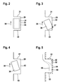
- FIG. 2 a first embodiment of possible parking positions in a parking space 29 is shown.
- the parking space 29, which is aligned parallel to a direction of travel 30, is bounded by a front boundary 31, by a lateral boundary 32 and by a rear boundary 33, respectively.
- the vehicle is guided into a parking position 34, in which it has a minimum distance during the parking process to the parking space boundaries 31, 32, 33.
- the parking position 34 is selected so that even after parking the vehicle a minimum distance to the parking space boundaries 31, 32, 33 is maintained.
- another parking position 35 is shown in dashed lines. In the parking position 35, the distance from the right parking space boundary 32 is reduced. In this case, only the lateral parking space boundary 32 has been entered or recorded as überragbar. The distance of the parking position 35 to the right parking space boundary 32 is reduced compared to the parking position 34.
- FIG. 3 an example of an implementation of a parking operation of a vehicle 36 in the parking space 29 is shown.
- the lateral parking space boundary 32 is designed as a superordinate parking space boundary.
- the vehicle 36 could be in the parking space 29th introduced, that a rear right corner 37, shown hatched, may extend beyond the right parking space boundary 32 during the parking process.
- FIG. 4 an alternative situation is shown in which a vehicle 38 is retracted into a larger parking space 39.
- a front parking space boundary 41, a lateral parking space boundary 42 and a rear parking space boundary 43 are provided, all of which are not traversable.
- the front and the rear parking space boundary 41, 43 may be formed for example by vehicles.
- the lateral parking space boundary 42 is formed for example by a house wall.
- the vehicle 38 can not now use the area beyond the parking space boundary 41, 42, 43 for a parking operation. Therefore, the vehicle 38 must be guided without touching the parking space boundaries 41, 42, 43 in the parking space 39.
- the parking space 39 must therefore be greater than the parking space 29, in which the respective lateral parking space boundaries can be surmounted.
- a first embodiment of a display display is in the FIG. 5 shown.
- a parking space 40 is shown, which is bounded by parking space boundaries on the front 51, on the longitudinal side 52 and on the back 53.
- the respective parking space boundaries 51, 52, 53 are each not überragbar.
- a first Einparkweg 55 and a second Einparkweg 56 may be shown in the display representation.
- the first Einparkweg 55 corresponds to the situation that none of the parking space limitations is überragbar.
- the second Einparkweg 56 corresponds to the situation in which the lateral parking space boundary 52 is überragbar.
- a user can now check whether the side parking space restriction 52 is actually not überragbar If this is überragbar, the vehicle can choose the second Einparkweg 56, then the icons 54 are changed at the side parking space boundary 52 in the display accordingly.
- the two parking tracks 55, 56 are displayed at the same time.
- both parking paths 55, 56 are possible, then the question of whether a lateral parking space limitation is überragbar, for a success of the parking operation is not crucial. However, if the length of the parking space is insufficient, parking may be successfully completed only if there is an excessively large lateral parking space boundary.
- each limitation is assumed to be non-transferable, that is to say the driver is shown in the display, for example, the situation according to FIG FIG. 5 shown.
- a überbarbare parking space limitation is only accepted according to this embodiment, when the driver has confirmed accordingly a Göragles the respective parking space boundary
- a Kochrag sadness for example, the front or the rear parking space boundary 52, 53 can also be considered meaningful.
- the vehicle front or the rear of the vehicle in the event that the front or the rear parking space boundary is überragbar be further moved forward or back accordingly, especially in a more spacious parking the vehicle accordingly to lead to a suitable parking position in the parking space.
- FIG. 6 an alternative display display is shown, in which also the parking space 40 is shown. Likewise, the non-communicable parking space boundaries 51 and 53 are shown.
- the lateral parking space boundary 52 is now characterized by a corresponding symbol 49 as a traversable parking space boundary. An observer can now recognize that, in the case of a parking operation controlled by the control device, a transferability of the right parking space boundary 52 is assumed.
Landscapes
- Engineering & Computer Science (AREA)
- Chemical & Material Sciences (AREA)
- Combustion & Propulsion (AREA)
- Transportation (AREA)
- Mechanical Engineering (AREA)
- Traffic Control Systems (AREA)
- Control Of Driving Devices And Active Controlling Of Vehicle (AREA)
- Steering Control In Accordance With Driving Conditions (AREA)
Description
Die Erfindung geht aus von einer Steuereinrichtung zur Einparkunterstützung und einem Verfahren zur Einparkunterstützung.The invention is based on a control device for parking assistance and a method for parking assistance.
Aus der
Aus der
Aus der
Aus der
Die erfindungsgemäße Steuereinrichtung zur Einparkunterstützung für ein Fahrzeug mit den Merkmalen des unabhängigen Anspruchs hat demgegenüber den Vorteil, dass eine Einparkbahn des Fahrzeugs in eine Parklücke unter einer Berücksichtigung einer möglichen Überragbarkeit einer jeweiligen Begrenzung einer Parklücke bestimmt wird. Eine Überragbarkeit einer Begrenzung einer Parklücke liegt dann vor, wenn Teile der Fahrzeugkarosserie, beispielsweise ein Stoßfänger, über eine erfasste Begrenzung der Parklücke hinaus die Begrenzung der Parklücke überragen kann. Dies kann beispielsweise dann der Fall sein, wenn der Stoßfänger über eine Bordsteinkante oder über eine niedrige Mauer hinausragen kann. In diesem Fall kann derjenige Bereich oberhalb der Begrenzung der Parklücke für den Einparkvorgang mit ausgenutzt werden, indem ein entsprechender Bereich des Fahrzeughecks oder der Fahrzeugfront über die Begrenzung der Parklücke hinaus geführt werden kann. Ist die Begrenzung der Parklücke beispielsweise als eine hohe Wand ausgeführt, so liegt keine Überragbarkeit der Begrenzung der Parklücke vor, da die Karosserie des Fahrzeugs einen Abstand zu der Mauer einhalten muss. In diesem Fall kann der Bereich oberhalb der Parklücke nicht zur Führung des Fahrzeughecks bzw. der Fahrzeugfront während des Einparkvorgangs berücksichtigt werden. Vielmehr muss das Fahrzeug auch im Bereich von äußeren Karosserieteilen, wie beispielsweise einem Außenspiegel oder einem Stoßfänger, stets beabstandet, möglicherweise einschließlich eines Sicherheitsabstandes, zu der Begrenzung der Parklücke während des Einparkvorgangs geführt werden.The control device according to the invention for parking assistance for a vehicle with the features of the independent claim has the advantage that a parking path of the vehicle is determined in a parking space under consideration of a possible Überragbarkeit a respective limitation of a parking space. A Überragbarkeit a limitation of a parking space is present when parts of the vehicle body, such as a bumper, beyond a detected boundary of the parking space beyond the limit of the parking space can extend beyond. This may for example be the case when the bumper can protrude over a curb or over a low wall. In this case, the area above the boundary of the parking space can be utilized for the parking process by allowing a corresponding area of the vehicle rear or the vehicle front to be guided beyond the limitation of the parking space. If the limitation of the parking space is designed, for example, as a high wall, then there is no outsourcing of the limitation of the parking space, since the body of the vehicle must maintain a distance from the wall. In this case, the area above the parking space can not be taken into account for guiding the vehicle rear or the vehicle front during the parking process. Rather, the vehicle must always be in the range of outer body parts, such as an exterior mirror or a bumper, always spaced, possibly including a safety margin, led to the limitation of the parking space during the parking process.
Liegt eine Überragbarkeit einer Begrenzung der Parklücke vor, so kann bei einer Berücksichtigung dieser Überragbarkeit der Einparkvorgang einfacher gestaltet werden, indem nämlich der Raum oberhalb der Begrenzung der Parklücke mittels einem entsprechenden Überragen durch Karosserieteile des Fahrzeugs mit ausgenutzt werden kann. Ist keine Überragbarkeit gegeben, so kann dieser Raum nicht ausgenutzt werden. Möglicherweise sind dann zusätzliche Einparkzüge erforderlich oder eine Parklücke ist möglicherweise für ein Einparken nicht geeignet. Indem bei einer Begrenzung einer Parklücke eine Überragbarkeit festgestellt oder eingegeben werden kann, kann gegebenenfalls auch eine ansonsten ungeeignete Parklücke für einen Einparkvorgang ausgenutzt werden. Ferner kann sich gegebenenfalls der Einparkweg verkürzen oder vereinfachen. Somit kann ein Einparkvorgang bei einer Berücksichtigung einer Überragbarkeit beschleunigt oder gegebenenfalls sogar überhaupt erst durchgeführt werden.If there is a Überragbarkeit a limitation of the parking space, it can be made simpler taking into account this Überragbarkeit the parking, namely by the space above the limit of the parking space can be exploited by means of a corresponding projection through body parts of the vehicle with. If there is no Überragbarkeit, so this room can not be exploited. You may need additional parking trains or a parking space may not be suitable for parking. By being able to ascertain or input portability when limiting a parking space, an otherwise unsuitable parking space may also be utilized for a parking operation. Furthermore, if necessary, the Einparkweg shorten or simplify. Thus, a parking process can be accelerated with consideration of a transferability or possibly even carried out in the first place.
Entsprechende Vorteile ergeben sich auch für ein Verfahren zur Einparkunterstützung für ein Fahrzeug gemäß dem nebengeordneten Patentanspruch.Corresponding advantages also result for a method for parking assistance for a vehicle according to the independent claim.
Durch die in den unabhängigen Ansprüchen aufgeführten Maßnahmen sind vorteilhafte Weiterbildungen und Verbesserungen der in dem unabhängigen Anspruch angegebenen Steuereinrichtung und des in dem unabhängigen Anspruch angegebenen Verfahrens möglich. So ist es vorteilhaft, dass die Steuereinrichtung eine Schnittstelle zu einer Eingabeeinheit aufweist, mit der ein Benutzer eine Überragbarkeit wenigstens einer Begrenzung der Parklücke eingeben kann. Selbst wenn eine Sensoreinheit zur Erfassung einer Begrenzung einer Parklücke nicht in der Lage ist, festzustellen, ob eine Überragbarkeit eines Hindernisses vorliegt, kann ein Benutzer, wenn er eine Überragbarkeit erkennt, beispielsweise eine Überragbarkeit einer Bordsteinkante, diese Überragbarkeit manuell eingeben.The measures listed in the independent claims advantageous refinements and improvements of the independent claim specified control device and the method specified in the independent claim are possible. Thus, it is advantageous for the control device to have an interface to an input unit with which a user can input a transferability of at least one limit of the parking space. Even if a sensor unit for detecting a limitation of a parking space is not able to determine whether an obstacle is overloadable, a user, if he detects a Überragbarkeit, such as a Übergestbarkeit a curb, manually enter this Überragbarkeit.
Weiterhin ist es erfindungsgemäß vorgesehen, eine Schnittstelle für eine Anzeige vorzusehen, um einem Benutzer eine Parklücke anzuzeigen und um ihm auch anzuzeigen, welche Begrenzungen der Parklücke als überragbar erfasst oder eingegeben wurden. Ein Benutzer kann somit erkennen, ob eine entsprechende Kennzeichnung einer Parklückenbegrenzung hinsichtlich ihrer Überragbarkeit zutreffend ist oder nicht. Somit wird sichergestellt, dass ein Benutzer für einen Einparkvorgang eine Rückmeldung darüber erhält, ob die Steuereinrichtung zur Einparkunterstützung eine Parklücke zutreffend als überragbar gekennzeichnet hat und für eine Berechnung eines Fahrweges in eine Parkposition in einer Parklücke berücksichtigt.Furthermore, it is provided according to the invention to provide an interface for a display in order to display a parking space to a user and also to indicate to him which limitations of the parking space as überragbar recorded or entered. A user can thus recognize whether or not a corresponding identification of a parking space boundary is applicable with regard to its portability. This ensures that a user receives feedback for a parking process as to whether the control device for parking assistance has correctly identified a parking space as überragbar and takes into account for a calculation of a driveway in a parking position in a parking space.
Weiterhin ist es vorteilhaft, eine Schnittstelle zu einer Eingabeeinheit zur Auswahl zwischen einem berechneten Fahrweg mit als überragbar angenommenen Begrenzungen und einem berechneten Fahrweg mit als nicht überragbar angenommenen Begrenzungen vorzusehen. Hierdurch ist eine besonders schnelle Auswahl aus sich aus einer unterschiedlichen Überragbarkeit der Begrenzungen ergebenden Fahrwege möglich.Furthermore, it is advantageous to provide an interface to an input unit for selecting between a calculated travel path with boundaries assumed to be transferable and a calculated travel path with limitations assumed to be unsustainable. As a result, a particularly fast selection of resulting from a different Überragbarkeit the limits resulting routes possible.
Weiterhin ist es vorteilhaft, eine Schnittstelle zur Ausgabe von Fahranweisungen zur zumindest teilweisen automatischen Steuerung des Fahrzeugs vorzusehen, um beispielsweise eine Lenkung automatisch anzusteuern, um das Fahrzeug automatisch in die gewünschte Parkposition in der Parklücke zu führen.Furthermore, it is advantageous to provide an interface for outputting driving instructions for the at least partial automatic control of the vehicle in order, for example, to control a steering automatically in order to automatically guide the vehicle into the desired parking position in the parking space.
Ferner ist es vorteilhaft, eine Parkposition in der Parklücke derart zu wählen, dass der Abstand der Parkposition von einer Begrenzung der Parklücke davon abhängt, ob eine jeweilige Begrenzung der Parklücke überragbar ist. Wird das Fahrzeug beispielsweise in eine Parklücke an einer hohen Mauer positioniert, so wird ein größerer Abstand eingehalten. Hiermit kann es einer Person, die an der jeweiligen Seite des Fahrzeugs das Fahrzeug verlassen muss, ermöglicht werden, bequem aus dem Fahrzeug auszusteigen. Ferner kann es auch gegebenenfalls noch ermöglicht werden, einen Kofferraumdeckel bequem zu öffnen. Wäre die entsprechende Begrenzung überragbar, beispielsweise eine Bordsteinkante, so kann die Parkposition sehr nahe an die Begrenzung der Parklücke geführt werden, da im Allgemeinen auch eine Öffnung der Türe oder ein Zugang zu einem Kofferraum über der überragbaren Parklückenbegrenzung problemlos möglich sein wird.Furthermore, it is advantageous to select a parking position in the parking space such that the distance of the parking position from a limitation of the parking space depends on whether a respective limitation of the parking space is überragbar. If the vehicle is positioned, for example, in a parking space on a high wall, a greater distance is maintained. This can make it possible for a person who has to leave the vehicle on the respective side of the vehicle to easily get out of the vehicle. Furthermore, it may also be possible to conveniently open a trunk lid. If the corresponding boundary were überragbar, such as a curb, the parking position can be performed very close to the limit of the parking space, as well as an opening of the door or access to a trunk over the überragbaren parking space boundary will be easily possible.
Es ist ferner vorteilhaft, eine mögliche Überragbarkeit durch Karosserieteile des Fahrzeugs davon abhängig zu machen, ob die jeweilige Begrenzung der Parklücke eine vorgegebene Höhe über einer Fahrfläche des Fahrzeugs nicht überschreitet. Die entsprechende Grenzhöhe wird durch die Abmessungen des Fahrzeugs vorgegeben. Ist das Fahrzeug beispielsweise tiefer gelegt, so kann eine entsprechende Grenzhöhe beispielsweise an eine heruntergezogene Front oder Heckschürze des Fahrzeugs angepasst werden. Ist das Fahrzeug beispielsweise als ein Geländewagen ausgeführt, so kann eine entsprechende Überragbarkeit höher gesetzt werden. Nach einer Grenzhöhenfestsetzung ist insbesondere eine nachfolgende automatische Festlegung einer Überragbarkeit auf einfache Weise möglich.It is also advantageous to make a possible Überragbarkeit by body parts of the vehicle depending on whether the respective limit of the parking space does not exceed a predetermined height above a running surface of the vehicle. The corresponding limit height is determined by the dimensions of the vehicle. If, for example, the vehicle is lowered, then a corresponding limit height can be adapted, for example, to a pulled-down front or rear apron of the vehicle. If the vehicle is designed, for example, as an off-road vehicle, an appropriate transferability can be set higher. After a limit height setting, in particular a subsequent automatic determination of a transferability is possible in a simple manner.
Ausführungsbeispiele der Erfindung sind in den Zeichnungen dargestellt und in der nachfolgenden Beschreibung näher erläutert.Embodiments of the invention are illustrated in the drawings and explained in more detail in the following description.
Es zeigen
-
Figur 1 eine schematische Darstellung eines Fahrzeugs mit einer erfindungsgemäßen Steuereinrichtung zur Einparkunterstützung, -
Figuren 2 bis 4 -
Figuren 56 Ausführungsbeispiele für Anzeigendarstellungen für die Durchführung des erfindungsgemäßen Verfahrens zur Einparkunterstützung.
-
FIG. 1 a schematic representation of a vehicle with a control device according to the invention for parking assistance, -
FIGS. 2 to 4 different parking situations to explain the method according to the invention for parking assistance, -
Figures 5 and6 Embodiments for display representations for carrying out the method according to the invention for parking assistance.
In der
In einer ersten Ausführungsform ist der Abstandssensor 3 dazu ausgelegt, lediglich Begrenzungen einer Parklücke zu erfassen. Entsprechend wird auch eine Bordsteinkante, die einen Straßenverlauf begrenzt als eine Begrenzung einer Parklücke aufgefasst. Insbesondere für den Fall, dass ein rückwärtiges Einparken in eine Parklücke erfolgen soll, die parallel zu einer Fahrtrichtung des Fahrzeugs führt, kann es jedoch vorteilhaft sein, wenn ein rechter Heckbereich die als Bordsteinkante ausgeführte Parklückenbegrenzung überragt. Ein entsprechender Heckbereich ist in der
Anstelle einer Bordsteinkante können auch beliebige andere überragbare Parklückenbegrenzungen als überragbar eingegeben werden. Beispielsweise können dies Markierungen sein, die lediglich auf einen Straßenbelag aufgetragen wurden. Insbesondere bei einer Erfassung einer Parklückenbegrenzung über einen als Videosensor ausgeführten Abstandssensor 3 kann möglicherweise eine derartige Begrenzung, die problemlos überfahren werden kann, bei einer Bahnplanung des Einparkwegs in die Parkposition als einschränkend aufgefasst werden.Instead of a curb, any other überragbare parking space limitations can be entered as überragbar. For example, these may be markings that have only been applied to a road surface. In particular, when detecting a parking space limitation via a distance sensor 3 designed as a video sensor, it is possible that such a boundary, which can be overridden without difficulty, may be regarded as limiting in a path planning of the parking path into the parking position.
In einer weiteren Ausführungsform kann der Abstandssensor 3 auch dazu ausgelegt sein, beispielsweise durch ein geeignetes Messverfahren, die jeweiligen Höhen von Parklückenbegrenzungen auszumessen. Durch einen Vergleich der gemessenen Höhe mit einer in dem Speicher 10 der Steuereinrichtung 5 abgelegten Höhe kann dann bestimmt werden, ob die jeweilige Parklückenbegrenzung als überragbar eingestuft werden kann oder nicht. Hierzu ist in dem Speicher 10 eine entsprechende fahrzeugspezifische Höhe abgelegt.In a further embodiment, the distance sensor 3 can also be designed, for example, by a suitable measuring method, the to measure the respective heights of parking space limitations. By comparing the measured height with a height stored in the
Gegebenenfalls kann über den Lautsprecher 11 und/oder über die Anzeige 12 auch eine Warnung ausgegeben werden, wenn ein Benutzer eine Parklückenbegrenzung als überragbar klassifiziert, während die Abstandssensoren 3, 15, 17 des Fahrzeugs 1 jedoch eine entsprechende Überragbarkeit nicht erkennen können.Optionally, via the
In der
In der
In der
Ein erstes Ausführungsbeispiel für eine Anzeigendarstellung ist in der
Gemäß dem Ausführungsbeispiel der
Sind beide Einparkbahnen 55, 56 möglich, so ist die Frage, ob eine seitliche Parklückenbegrenzung überragbar ist, für einen Erfolg des Einparkvorgangs nicht entscheidend. Reicht die Länge der Parklücke jedoch nicht aus, so kann gegebenenfalls nur bei einer überragbaren seitlichen Parklückenbegrenzung ein Einparkvorgang erfolgreich abgeschlossen werden.If both
In einer Ausführungsform wird zunächst jede Begrenzung als nicht überragbar angenommen, dass heißt dem Fahrer wird beispielsweise in der Anzeige die Situation gemäß der
Eine Überragbarkeit beispielsweise der vorderen oder der hinteren Parklückenbegrenzung 52, 53 kann ebenfalls sinnvoll berücksichtigt werden. So kann die Fahrzeugfront oder das Fahrzeugheck für den Fall, dass die vordere oder die hintere Parklückenbegrenzung überragbar ist, entsprechend weiter vor bzw. zurück bewegt werden, um insbesondere bei einem mehrzügigen Einparken das Fahrzeug entsprechend in eine geeignete Parkposition in der Parklücke zu führen.A Überragbarkeit for example, the front or the rear
In der
Claims (8)
- Control device (5) for assisting a parking process for a vehicle, having an interface (4) with a sensor unit (3) for sensing the boundary of a parking space (29) in the surroundings of the vehicle (1), having a computing unit (9) for determining a path to a parking position (34, 35) in the parking space (29), characterized in that the computing unit (9) is configured to calculate a path (55, 56) to the parked position (34, 35) taking into account the possibility of bodywork parts (19) of the vehicle (1) projecting beyond the boundary (31, 32, 33) of the parking space (29), wherein a display (12) and an interface with the display (12) for displaying boundaries (51, 52, 53) of the parking space are provided, wherein the boundaries (51, 52, 53) of the parking space are each characterized as to whether the vehicle can project beyond them.
- Control device according to Claim 1, characterized by an interface with an input unit (20) for inputting a possibility of parts of the vehicle projecting beyond the boundary (31, 32, 33) of the parking space (29).
- Control device according to one of the preceding claims, characterized by an interface with an input unit (20) for selecting between a calculated path (56) into a parking space with a boundary beyond which it is assumed it is possible to project and a calculated path (55) into the parking space with a boundary beyond which it is assumed it is not possible to project.
- Control device according to one of the preceding claims, characterized by an interface for inputting driving instructions for at least partially automatically steering the vehicle into the parking space.
- Method for assisting a parking process of a vehicle, wherein a boundary (31, 32, 33) of a parking space (29) in the surroundings of the vehicle (1) is sensed, wherein a path (55, 56) to a parked position (34, 35) in the parking space is determined, characterized in that a selection is made between the possibility of parts of the vehicle projecting beyond, and a lack of a possibility of parts of the vehicle projecting beyond, the boundary of the parking space, and in that a path into the parking space is calculated taking into account a possibility of projection beyond the boundary of the parking space, wherein in a display the boundaries of the parking space are displayed, wherein the boundaries of the parking space are each characterized as to whether the vehicle can project beyond them.
- Method according to Claim 5, characterized in that a parked position in the parking space is selected in such a way that the distance between the parked position and a boundary of the parking space depends on whether there is a possibility of projection beyond the parking space.
- Method according to one of Claims 5-6, characterized in that the possibility of parts of the vehicle projecting beyond the boundary of the parking space is input by a user or is determined from measurement variables.
- Method according to one of Claims 5-7, characterized in that a possibility of bodywork parts of the vehicle projecting beyond the boundary of the parking space is present if the boundary of the parking space does not exceed a predefined height above the driving surface of the vehicle.
Applications Claiming Priority (2)
| Application Number | Priority Date | Filing Date | Title |
|---|---|---|---|
| DE102008044073A DE102008044073A1 (en) | 2008-11-26 | 2008-11-26 | Control device for parking assistance |
| PCT/EP2009/063459 WO2010060681A1 (en) | 2008-11-26 | 2009-10-15 | Control device for assisting the parking process |
Publications (2)
| Publication Number | Publication Date |
|---|---|
| EP2370306A1 EP2370306A1 (en) | 2011-10-05 |
| EP2370306B1 true EP2370306B1 (en) | 2014-04-16 |
Family
ID=41549898
Family Applications (1)
| Application Number | Title | Priority Date | Filing Date |
|---|---|---|---|
| EP09747803.6A Not-in-force EP2370306B1 (en) | 2008-11-26 | 2009-10-15 | Control device for assisting the parking process |
Country Status (4)
| Country | Link |
|---|---|
| US (1) | US8918254B2 (en) |
| EP (1) | EP2370306B1 (en) |
| DE (1) | DE102008044073A1 (en) |
| WO (1) | WO2010060681A1 (en) |
Cited By (1)
| Publication number | Priority date | Publication date | Assignee | Title |
|---|---|---|---|---|
| DE102016122749A1 (en) | 2016-11-25 | 2018-05-30 | Valeo Schalter Und Sensoren Gmbh | A method for assisting a driver of a motor vehicle in a parking operation, computing device, driver assistance system and motor vehicle |
Families Citing this family (13)
| Publication number | Priority date | Publication date | Assignee | Title |
|---|---|---|---|---|
| DE102010030466B4 (en) | 2010-06-24 | 2021-05-20 | Robert Bosch Gmbh | Procedure for warning a driver of a collision |
| DE102010034142A1 (en) * | 2010-08-12 | 2012-02-16 | Valeo Schalter Und Sensoren Gmbh | A method of assisting a driver in driving a motor vehicle and driver assistance system |
| EP2428431A1 (en) * | 2010-09-08 | 2012-03-14 | Ford Global Technologies, LLC | Vehicele park assist system and method for parking a vehicle using such system |
| US20150197281A1 (en) * | 2011-04-19 | 2015-07-16 | Ford Global Technologies, Llc | Trailer backup assist system with lane marker detection |
| DE102011109491A1 (en) * | 2011-08-04 | 2013-02-07 | GM Global Technology Operations LLC (n. d. Gesetzen des Staates Delaware) | Driving assistance device to support the driving of narrow roads |
| KR101316501B1 (en) * | 2011-10-14 | 2013-10-10 | 현대자동차주식회사 | Parking area detection system and method thereof using mesh space analysis |
| AU2013227999A1 (en) | 2012-09-13 | 2014-03-27 | Technological Resources Pty Ltd | A system for, and a method of, controlling operation of a vehicle in a defined area |
| US9002564B2 (en) * | 2013-04-23 | 2015-04-07 | Ford Global Technologies, Llc | Enhanced park assist wheel speed compensation technique |
| US10185319B2 (en) * | 2015-11-16 | 2019-01-22 | Ford Global Technologies, Llc | Method and device for assisting a parking maneuver |
| DE102017204271A1 (en) * | 2017-03-15 | 2018-09-20 | Bayerische Motoren Werke Aktiengesellschaft | Optimal climate conditioning when parking |
| GB201712004D0 (en) * | 2017-07-26 | 2017-09-06 | Jaguar Land Rover Ltd | Proximity sensing systems and their control |
| JP7205701B2 (en) * | 2019-10-11 | 2023-01-17 | トヨタ自動車株式会社 | vehicle alarm |
| DE102020131281A1 (en) | 2020-11-26 | 2022-06-02 | Valeo Schalter Und Sensoren Gmbh | METHOD OF OPERATING A DRIVING ASSISTANCE SYSTEM, COMPUTER PROGRAM PRODUCT, DRIVING ASSISTANCE SYSTEM AND VEHICLE |
Citations (1)
| Publication number | Priority date | Publication date | Assignee | Title |
|---|---|---|---|---|
| US20050231341A1 (en) * | 2004-04-02 | 2005-10-20 | Denso Corporation | Vehicle periphery monitoring system |
Family Cites Families (12)
| Publication number | Priority date | Publication date | Assignee | Title |
|---|---|---|---|---|
| DE19829731A1 (en) * | 1998-07-03 | 2000-01-05 | Mannesmann Vdo Ag | Motor vehicle with tailgate |
| JP4615766B2 (en) * | 2000-12-15 | 2011-01-19 | 本田技研工業株式会社 | Parking assistance device |
| DE10257722A1 (en) | 2002-12-11 | 2004-07-01 | Robert Bosch Gmbh | parking aid |
| JP4427953B2 (en) * | 2003-01-29 | 2010-03-10 | 株式会社豊田自動織機 | Parking assistance device |
| DE10312611A1 (en) * | 2003-03-21 | 2004-09-30 | Daimlerchrysler Ag | Method and device for detecting an object in the environment of a motor vehicle |
| DE10317044A1 (en) | 2003-04-11 | 2004-10-21 | Daimlerchrysler Ag | Optical monitoring system for use in maneuvering road vehicles provides virtual guide surfaces to ensure collision free movement |
| DE102005027165B4 (en) * | 2005-06-13 | 2024-01-25 | Robert Bosch Gmbh | Method and device for issuing parking instructions |
| DE102005038524A1 (en) | 2005-08-02 | 2007-02-15 | Valeo Schalter Und Sensoren Gmbh | Method for determining the depth limit of a parking space by means of ultrasonic sensors and system for this purpose |
| DE102005037468A1 (en) | 2005-08-09 | 2007-02-15 | Robert Bosch Gmbh | Device and method for supporting a parking operation of a vehicle |
| DE102005044050A1 (en) * | 2005-09-15 | 2007-03-22 | Hella Kgaa Hueck & Co. | Method for parking space determination for motor vehicles |
| JP4769625B2 (en) * | 2006-04-25 | 2011-09-07 | トヨタ自動車株式会社 | Parking assistance device and parking assistance method |
| DE102007035219A1 (en) | 2007-07-25 | 2009-01-29 | Robert Bosch Gmbh | Object classification method and parking assistance system |
-
2008
- 2008-11-26 DE DE102008044073A patent/DE102008044073A1/en not_active Withdrawn
-
2009
- 2009-10-15 WO PCT/EP2009/063459 patent/WO2010060681A1/en active Application Filing
- 2009-10-15 EP EP09747803.6A patent/EP2370306B1/en not_active Not-in-force
- 2009-10-15 US US12/998,751 patent/US8918254B2/en not_active Expired - Fee Related
Patent Citations (1)
| Publication number | Priority date | Publication date | Assignee | Title |
|---|---|---|---|---|
| US20050231341A1 (en) * | 2004-04-02 | 2005-10-20 | Denso Corporation | Vehicle periphery monitoring system |
Cited By (1)
| Publication number | Priority date | Publication date | Assignee | Title |
|---|---|---|---|---|
| DE102016122749A1 (en) | 2016-11-25 | 2018-05-30 | Valeo Schalter Und Sensoren Gmbh | A method for assisting a driver of a motor vehicle in a parking operation, computing device, driver assistance system and motor vehicle |
Also Published As
| Publication number | Publication date |
|---|---|
| US8918254B2 (en) | 2014-12-23 |
| US20110288727A1 (en) | 2011-11-24 |
| DE102008044073A1 (en) | 2010-05-27 |
| EP2370306A1 (en) | 2011-10-05 |
| WO2010060681A1 (en) | 2010-06-03 |
Similar Documents
| Publication | Publication Date | Title |
|---|---|---|
| EP2370306B1 (en) | Control device for assisting the parking process | |
| EP2203329B1 (en) | Control device for a display device of a parking device, and representation method | |
| EP1886094B1 (en) | Driver assistance method | |
| DE102005050576B4 (en) | Parking assistance system and parking assistance method | |
| DE102008036009B4 (en) | Method for collision protection of a motor vehicle and parking garage assistant | |
| EP2089266B1 (en) | Parking steering assistant with improved transverse parking function | |
| EP1904342A1 (en) | Parking device | |
| EP1447271B1 (en) | Apparatus and method for monitoring of the proximity of a vehicle to avoid collisions with obstacles, in particular for parking | |
| EP1536978B1 (en) | Vehicle environment detection device | |
| EP1562054A2 (en) | Device for assisting a driver of a vehicle | |
| DE102013214660B4 (en) | Method and device for assisting a driver of a vehicle at the termination of an already started parking operation | |
| EP1475765A2 (en) | Apparatus for determining the possibility of a passage for a vehicle | |
| DE102010030213A1 (en) | Parking assistance system for transverse parking spaces | |
| WO2009013054A1 (en) | Object classification method and parking assistance system | |
| DE102009028451A1 (en) | Collision monitoring for a motor vehicle | |
| EP2504827A1 (en) | Method for warning of an object in the vicinity of a vehicle and driving assistance system | |
| DE10321904A1 (en) | Motor vehicle parking assistance system has approach sensors, steering angle sensor and a path traveled sensor linked to an evaluating computer unit | |
| EP1878615A1 (en) | Warning device and method for monitoring an environment | |
| DE102005029993A1 (en) | Method of aiding vehicle driver into finding suitable vehicle parking space, uses quality factor which is function of accuracy in length/width of parking space and quality of parking space evaluation based on length/width | |
| DE102011104740A1 (en) | Blind spot monitoring method for vehicle i.e. passenger car, involves performing recognition of objects in surrounding region of vehicle based on verification of radar data of radar detectors and ultrasound data of ultrasonic sensors | |
| DE102016122294A1 (en) | Planning a trajectory for autonomous parking of a motor vehicle in a parking lot environment | |
| DE102013021827A1 (en) | A method for warning a driver of a motor vehicle of a risk of collision by outputting a non-optical warning signal, collision warning system and motor vehicle | |
| EP2689991A2 (en) | Device and method for assisting a driver when parking | |
| EP3318470B1 (en) | Method for selecting a parking zone from a plurality of parking zones for a motor vehicle within a park area, parking assistance system for a motor vehicle and motor vehicle with a parking assistance system | |
| EP0936472B1 (en) | Method and device for testing the functioning of a distance controlling device in a car |
Legal Events
| Date | Code | Title | Description |
|---|---|---|---|
| PUAI | Public reference made under article 153(3) epc to a published international application that has entered the european phase |
Free format text: ORIGINAL CODE: 0009012 |
|
| 17P | Request for examination filed |
Effective date: 20110627 |
|
| AK | Designated contracting states |
Kind code of ref document: A1 Designated state(s): AT BE BG CH CY CZ DE DK EE ES FI FR GB GR HR HU IE IS IT LI LT LU LV MC MK MT NL NO PL PT RO SE SI SK SM TR |
|
| DAX | Request for extension of the european patent (deleted) | ||
| 17Q | First examination report despatched |
Effective date: 20120411 |
|
| GRAP | Despatch of communication of intention to grant a patent |
Free format text: ORIGINAL CODE: EPIDOSNIGR1 |
|
| INTG | Intention to grant announced |
Effective date: 20140117 |
|
| GRAS | Grant fee paid |
Free format text: ORIGINAL CODE: EPIDOSNIGR3 |
|
| GRAA | (expected) grant |
Free format text: ORIGINAL CODE: 0009210 |
|
| AK | Designated contracting states |
Kind code of ref document: B1 Designated state(s): AT BE BG CH CY CZ DE DK EE ES FI FR GB GR HR HU IE IS IT LI LT LU LV MC MK MT NL NO PL PT RO SE SI SK SM TR |
|
| REG | Reference to a national code |
Ref country code: GB Ref legal event code: FG4D Free format text: NOT ENGLISH |
|
| REG | Reference to a national code |
Ref country code: CH Ref legal event code: EP |
|
| REG | Reference to a national code |
Ref country code: AT Ref legal event code: REF Ref document number: 662334 Country of ref document: AT Kind code of ref document: T Effective date: 20140515 |
|
| REG | Reference to a national code |
Ref country code: IE Ref legal event code: FG4D Free format text: LANGUAGE OF EP DOCUMENT: GERMAN |
|
| REG | Reference to a national code |
Ref country code: DE Ref legal event code: R096 Ref document number: 502009009195 Country of ref document: DE Effective date: 20140528 |
|
| REG | Reference to a national code |
Ref country code: NL Ref legal event code: VDEP Effective date: 20140416 |
|
| REG | Reference to a national code |
Ref country code: LT Ref legal event code: MG4D |
|
| PG25 | Lapsed in a contracting state [announced via postgrant information from national office to epo] |
Ref country code: IS Free format text: LAPSE BECAUSE OF FAILURE TO SUBMIT A TRANSLATION OF THE DESCRIPTION OR TO PAY THE FEE WITHIN THE PRESCRIBED TIME-LIMIT Effective date: 20140816 Ref country code: BG Free format text: LAPSE BECAUSE OF FAILURE TO SUBMIT A TRANSLATION OF THE DESCRIPTION OR TO PAY THE FEE WITHIN THE PRESCRIBED TIME-LIMIT Effective date: 20140716 Ref country code: LT Free format text: LAPSE BECAUSE OF FAILURE TO SUBMIT A TRANSLATION OF THE DESCRIPTION OR TO PAY THE FEE WITHIN THE PRESCRIBED TIME-LIMIT Effective date: 20140416 Ref country code: NL Free format text: LAPSE BECAUSE OF FAILURE TO SUBMIT A TRANSLATION OF THE DESCRIPTION OR TO PAY THE FEE WITHIN THE PRESCRIBED TIME-LIMIT Effective date: 20140416 Ref country code: FI Free format text: LAPSE BECAUSE OF FAILURE TO SUBMIT A TRANSLATION OF THE DESCRIPTION OR TO PAY THE FEE WITHIN THE PRESCRIBED TIME-LIMIT Effective date: 20140416 Ref country code: NO Free format text: LAPSE BECAUSE OF FAILURE TO SUBMIT A TRANSLATION OF THE DESCRIPTION OR TO PAY THE FEE WITHIN THE PRESCRIBED TIME-LIMIT Effective date: 20140716 Ref country code: CY Free format text: LAPSE BECAUSE OF FAILURE TO SUBMIT A TRANSLATION OF THE DESCRIPTION OR TO PAY THE FEE WITHIN THE PRESCRIBED TIME-LIMIT Effective date: 20140416 Ref country code: GR Free format text: LAPSE BECAUSE OF FAILURE TO SUBMIT A TRANSLATION OF THE DESCRIPTION OR TO PAY THE FEE WITHIN THE PRESCRIBED TIME-LIMIT Effective date: 20140717 |
|
| PG25 | Lapsed in a contracting state [announced via postgrant information from national office to epo] |
Ref country code: ES Free format text: LAPSE BECAUSE OF FAILURE TO SUBMIT A TRANSLATION OF THE DESCRIPTION OR TO PAY THE FEE WITHIN THE PRESCRIBED TIME-LIMIT Effective date: 20140416 Ref country code: SE Free format text: LAPSE BECAUSE OF FAILURE TO SUBMIT A TRANSLATION OF THE DESCRIPTION OR TO PAY THE FEE WITHIN THE PRESCRIBED TIME-LIMIT Effective date: 20140416 Ref country code: LV Free format text: LAPSE BECAUSE OF FAILURE TO SUBMIT A TRANSLATION OF THE DESCRIPTION OR TO PAY THE FEE WITHIN THE PRESCRIBED TIME-LIMIT Effective date: 20140416 Ref country code: HR Free format text: LAPSE BECAUSE OF FAILURE TO SUBMIT A TRANSLATION OF THE DESCRIPTION OR TO PAY THE FEE WITHIN THE PRESCRIBED TIME-LIMIT Effective date: 20140416 Ref country code: PL Free format text: LAPSE BECAUSE OF FAILURE TO SUBMIT A TRANSLATION OF THE DESCRIPTION OR TO PAY THE FEE WITHIN THE PRESCRIBED TIME-LIMIT Effective date: 20140416 |
|
| PG25 | Lapsed in a contracting state [announced via postgrant information from national office to epo] |
Ref country code: PT Free format text: LAPSE BECAUSE OF FAILURE TO SUBMIT A TRANSLATION OF THE DESCRIPTION OR TO PAY THE FEE WITHIN THE PRESCRIBED TIME-LIMIT Effective date: 20140818 |
|
| REG | Reference to a national code |
Ref country code: DE Ref legal event code: R097 Ref document number: 502009009195 Country of ref document: DE |
|
| PG25 | Lapsed in a contracting state [announced via postgrant information from national office to epo] |
Ref country code: DK Free format text: LAPSE BECAUSE OF FAILURE TO SUBMIT A TRANSLATION OF THE DESCRIPTION OR TO PAY THE FEE WITHIN THE PRESCRIBED TIME-LIMIT Effective date: 20140416 Ref country code: SK Free format text: LAPSE BECAUSE OF FAILURE TO SUBMIT A TRANSLATION OF THE DESCRIPTION OR TO PAY THE FEE WITHIN THE PRESCRIBED TIME-LIMIT Effective date: 20140416 Ref country code: EE Free format text: LAPSE BECAUSE OF FAILURE TO SUBMIT A TRANSLATION OF THE DESCRIPTION OR TO PAY THE FEE WITHIN THE PRESCRIBED TIME-LIMIT Effective date: 20140416 Ref country code: RO Free format text: LAPSE BECAUSE OF FAILURE TO SUBMIT A TRANSLATION OF THE DESCRIPTION OR TO PAY THE FEE WITHIN THE PRESCRIBED TIME-LIMIT Effective date: 20140416 Ref country code: CZ Free format text: LAPSE BECAUSE OF FAILURE TO SUBMIT A TRANSLATION OF THE DESCRIPTION OR TO PAY THE FEE WITHIN THE PRESCRIBED TIME-LIMIT Effective date: 20140416 |
|
| PLBE | No opposition filed within time limit |
Free format text: ORIGINAL CODE: 0009261 |
|
| STAA | Information on the status of an ep patent application or granted ep patent |
Free format text: STATUS: NO OPPOSITION FILED WITHIN TIME LIMIT |
|
| 26N | No opposition filed |
Effective date: 20150119 |
|
| PG25 | Lapsed in a contracting state [announced via postgrant information from national office to epo] |
Ref country code: IT Free format text: LAPSE BECAUSE OF FAILURE TO SUBMIT A TRANSLATION OF THE DESCRIPTION OR TO PAY THE FEE WITHIN THE PRESCRIBED TIME-LIMIT Effective date: 20140416 |
|
| REG | Reference to a national code |
Ref country code: DE Ref legal event code: R097 Ref document number: 502009009195 Country of ref document: DE Effective date: 20150119 |
|
| PG25 | Lapsed in a contracting state [announced via postgrant information from national office to epo] |
Ref country code: MC Free format text: LAPSE BECAUSE OF FAILURE TO SUBMIT A TRANSLATION OF THE DESCRIPTION OR TO PAY THE FEE WITHIN THE PRESCRIBED TIME-LIMIT Effective date: 20140416 Ref country code: LU Free format text: LAPSE BECAUSE OF FAILURE TO SUBMIT A TRANSLATION OF THE DESCRIPTION OR TO PAY THE FEE WITHIN THE PRESCRIBED TIME-LIMIT Effective date: 20141015 |
|
| REG | Reference to a national code |
Ref country code: CH Ref legal event code: PL |
|
| PG25 | Lapsed in a contracting state [announced via postgrant information from national office to epo] |
Ref country code: BE Free format text: LAPSE BECAUSE OF NON-PAYMENT OF DUE FEES Effective date: 20141031 |
|
| REG | Reference to a national code |
Ref country code: IE Ref legal event code: MM4A |
|
| PG25 | Lapsed in a contracting state [announced via postgrant information from national office to epo] |
Ref country code: SI Free format text: LAPSE BECAUSE OF FAILURE TO SUBMIT A TRANSLATION OF THE DESCRIPTION OR TO PAY THE FEE WITHIN THE PRESCRIBED TIME-LIMIT Effective date: 20140416 Ref country code: CH Free format text: LAPSE BECAUSE OF NON-PAYMENT OF DUE FEES Effective date: 20141031 Ref country code: LI Free format text: LAPSE BECAUSE OF NON-PAYMENT OF DUE FEES Effective date: 20141031 |
|
| REG | Reference to a national code |
Ref country code: FR Ref legal event code: PLFP Year of fee payment: 7 |
|
| PG25 | Lapsed in a contracting state [announced via postgrant information from national office to epo] |
Ref country code: IE Free format text: LAPSE BECAUSE OF NON-PAYMENT OF DUE FEES Effective date: 20141015 |
|
| REG | Reference to a national code |
Ref country code: AT Ref legal event code: MM01 Ref document number: 662334 Country of ref document: AT Kind code of ref document: T Effective date: 20141015 |
|
| PG25 | Lapsed in a contracting state [announced via postgrant information from national office to epo] |
Ref country code: AT Free format text: LAPSE BECAUSE OF NON-PAYMENT OF DUE FEES Effective date: 20141015 |
|
| PG25 | Lapsed in a contracting state [announced via postgrant information from national office to epo] |
Ref country code: SM Free format text: LAPSE BECAUSE OF FAILURE TO SUBMIT A TRANSLATION OF THE DESCRIPTION OR TO PAY THE FEE WITHIN THE PRESCRIBED TIME-LIMIT Effective date: 20140416 |
|
| PG25 | Lapsed in a contracting state [announced via postgrant information from national office to epo] |
Ref country code: HU Free format text: LAPSE BECAUSE OF FAILURE TO SUBMIT A TRANSLATION OF THE DESCRIPTION OR TO PAY THE FEE WITHIN THE PRESCRIBED TIME-LIMIT; INVALID AB INITIO Effective date: 20091015 Ref country code: TR Free format text: LAPSE BECAUSE OF FAILURE TO SUBMIT A TRANSLATION OF THE DESCRIPTION OR TO PAY THE FEE WITHIN THE PRESCRIBED TIME-LIMIT Effective date: 20140416 Ref country code: MT Free format text: LAPSE BECAUSE OF FAILURE TO SUBMIT A TRANSLATION OF THE DESCRIPTION OR TO PAY THE FEE WITHIN THE PRESCRIBED TIME-LIMIT Effective date: 20140416 |
|
| REG | Reference to a national code |
Ref country code: FR Ref legal event code: PLFP Year of fee payment: 8 |
|
| REG | Reference to a national code |
Ref country code: FR Ref legal event code: PLFP Year of fee payment: 9 |
|
| PG25 | Lapsed in a contracting state [announced via postgrant information from national office to epo] |
Ref country code: MK Free format text: LAPSE BECAUSE OF FAILURE TO SUBMIT A TRANSLATION OF THE DESCRIPTION OR TO PAY THE FEE WITHIN THE PRESCRIBED TIME-LIMIT Effective date: 20140416 |
|
| REG | Reference to a national code |
Ref country code: FR Ref legal event code: PLFP Year of fee payment: 10 |
|
| PGFP | Annual fee paid to national office [announced via postgrant information from national office to epo] |
Ref country code: FR Payment date: 20201020 Year of fee payment: 12 Ref country code: GB Payment date: 20201022 Year of fee payment: 12 |
|
| PGFP | Annual fee paid to national office [announced via postgrant information from national office to epo] |
Ref country code: DE Payment date: 20211214 Year of fee payment: 13 |
|
| GBPC | Gb: european patent ceased through non-payment of renewal fee |
Effective date: 20211015 |
|
| PG25 | Lapsed in a contracting state [announced via postgrant information from national office to epo] |
Ref country code: GB Free format text: LAPSE BECAUSE OF NON-PAYMENT OF DUE FEES Effective date: 20211015 |
|
| PG25 | Lapsed in a contracting state [announced via postgrant information from national office to epo] |
Ref country code: FR Free format text: LAPSE BECAUSE OF NON-PAYMENT OF DUE FEES Effective date: 20211031 |
|
| REG | Reference to a national code |
Ref country code: DE Ref legal event code: R119 Ref document number: 502009009195 Country of ref document: DE |
|
| PG25 | Lapsed in a contracting state [announced via postgrant information from national office to epo] |
Ref country code: DE Free format text: LAPSE BECAUSE OF NON-PAYMENT OF DUE FEES Effective date: 20230503 |